

Mettler Toledo ID7-Base2000, MultiRange ID7-Base 2000 User Manual
Operating instructions and installation information
METTLER TOLEDO MultiRange
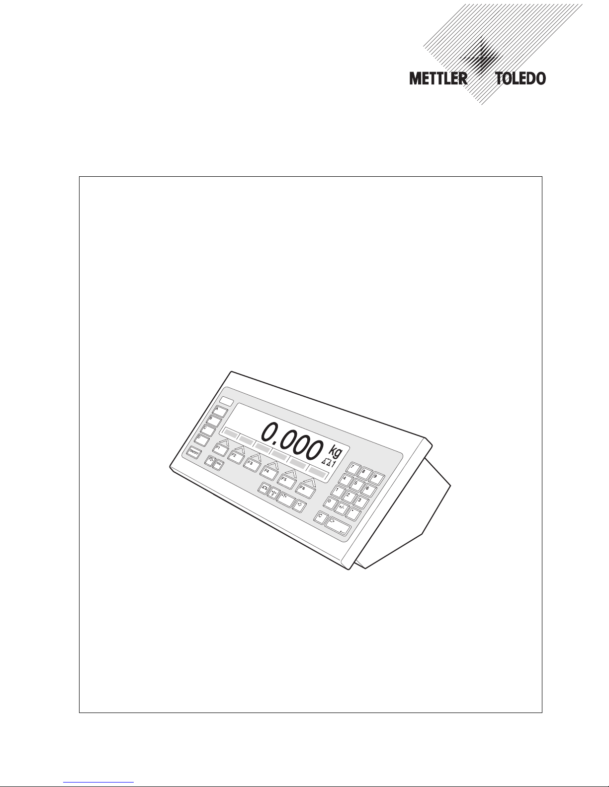
ID7-Base
2000
weighing terminal

These operating instructions and installation information 22004109D describe the following components:
ID7-Desk
Base
2000
-ID7
IDNet-ID7 (1 x Standard)
RS232-ID7 (1 x Standard)
BIG WEIGHT
®
is a registered trademark of Mettler-Toledo (Albstadt) GmbH
This equipment has been tested and found to comply with the limits for a Class A digital device, pursuant to both
parts of the FCC Rules and the radio interference regulations of the Canadian Department of Communications.
These limits are designed to provide reasonable protection against harmful interference when the equipment is
operated in a commercial environment. This equipment generates, uses and can radiate radio frequency energy
and, if not installed and used in accordance with the instruction manual, may cause harmful interference to radio
communications. Operation of this equipment in a residential area is like to cause harmful interference in which
case the user will be required to correct the interference at his own expense.

Contents
Operating instructions and installation information 22004109D 04/10 1
ID7-Base
Contents
Page
1 Introduction and commissioning................................................... 3
1.1 Safety precautions ........................................................................ 3
1.2 Applications ................................................................................. 3
1.3 ID7-Base weighing terminal ........................................................... 4
1.4 Commissioning............................................................................ 7
1.5 Cleaning ...................................................................................... 9
2 Basic functions............................................................................ 10
2.1 Switching on and off ..................................................................... 10
2.2 Setting to zero .............................................................................. 10
2.3 Taring ......................................................................................... 11
2.4 Weighing ..................................................................................... 12
2.5 Switch over weighing platform........................................................ 13
3 Additional functions..................................................................... 14
3.1 Weighing with the DeltaTrac........................................................... 14
3.2 Dynamic weighing........................................................................ 17
3.3 Change weight unit ....................................................................... 17
3.4 Working in a higher resolution ....................................................... 18
3.5 Display gross weight..................................................................... 18
3.6 Specifying dynamic set points ........................................................ 18
3.7 Multiplicative tare function ............................................................. 19
3.8 Additive tare function..................................................................... 19
3.9 Sandwich tare.............................................................................. 19
3.10 Display ID code and test weighing platform ..................................... 20
3.11 Identifications............................................................................... 20
3.12 Recall information......................................................................... 22
3.13 Print or transfer data ..................................................................... 23
3.14 Enter values with barcode reader.................................................... 23
3.15 Working with external keypad ........................................................ 24
3.16 Working with a second display ...................................................... 25
4 Settings in the master mode ........................................................ 26
4.1 Overview of the master mode ......................................................... 26
4.2 Operating the master mode............................................................ 27
4.3 TERMINAL master mode block........................................................ 28
4.4 SCALE master mode block ............................................................. 35
4.5 INTERFACE master mode block ...................................................... 38
5 Interface description .................................................................... 52
5.1 MMR command set....................................................................... 52
5.2 METTLER TOLEDO continuous mode............................................... 63
5.3 METTLER TOLEDO SICS command set............................................. 65

Contents
2 Operating instructions and installation information 22004109D 04/10
ID7-Base
6 Application blocks ....................................................................... 80
6.1 Syntax and formats....................................................................... 80
6.2 TERMINAL, SCALE application blocks.............................................. 83
6.3 INTERFACE application blocks........................................................ 87
7 What to do if …?......................................................................... 90
8 Technical data and accessories.................................................... 93
8.1 Technical data ............................................................................. 93
8.2 Accessories ................................................................................. 97
9 Appendix .................................................................................... 101
9.1 ASCII table ................................................................................... 101
9.2 Key numbers ............................................................................... 102
9.3 Opening/closing ID7-Base weighing terminal................................... 103
9.4 Configuring Pin 5 on RS232-ID7 interface....................................... 103
10 Index.......................................................................................... 104
Introduction and commissioning
Operating instructions and installation information 22004109D 04/10 3
ID7-Base
1 Introduction and commissioning
1.1 Safety precautions
▲ Never operate the ID7-Base weighing terminal in hazardous areas; there are
special scales in our product line for this purpose.
▲ Make sure that the electrical outlet for the ID7-Base weighing terminal is
grounded and easily accessible to that it can be isolated quickly in emergencies.
▲ Make sure that the mains voltage at the installation location is within the range
from 100 V to 240 V.
▲ The safety of the unit is endangered if it is not operated in accordance with these
operating instructions.
▲ Only authorized personnel may open the ID7-Base weighing terminal.
1.2 Applications
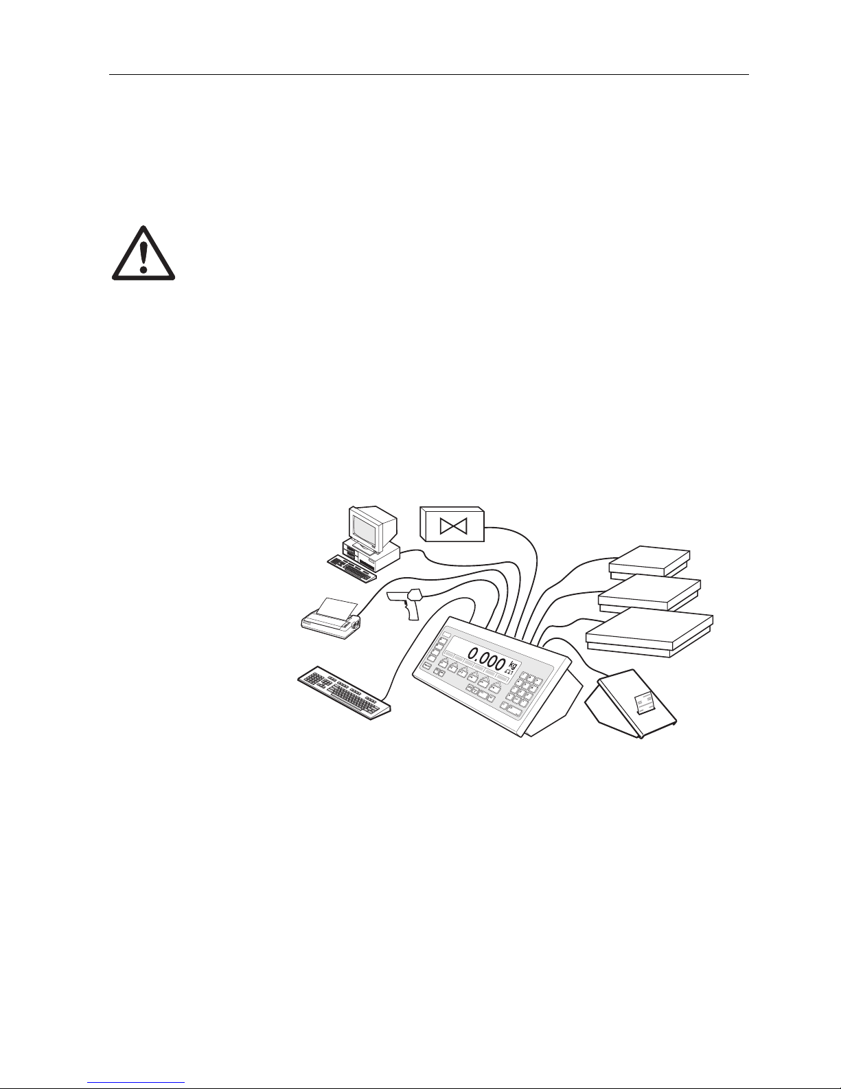
With the ID7-Base weighing terminal the following applications are possible:
• Multi-scale operation with up to 3 weighing platforms, including a weighing
platform with an analog signal output.
• Up to 6 data interfaces
– for printing,
– for data exchange with a computer,
– for connecting a barcode reader,
– for control, e.g. of valves or flaps,
– for connecting reference scales.
• Comfortable alphanumeric entry via an external keypad.
Introduction and commissioning
4 Operating instructions and installation information 22004109D 04/10
ID7-Base
1.3 ID7-Base weighing terminal
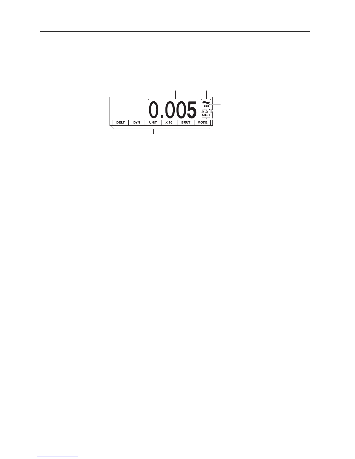
1.3.1 Display
1 Weight display BIG WEIGHT
®
with sign and decimal point
2 Stability monitor: lights up until the weighing platform has levelled out, then the
weight unit appears here
3 Range display for multi-range weighing platforms
4 Number of the weighing platform: shows the weighting platform just selected
5 NET symbol for marking net weight values
6 Assignment of the function keys
12
4
5
6
3
Introduction and commissioning
Operating instructions and installation information 22004109D 04/10 5
ID7-Base
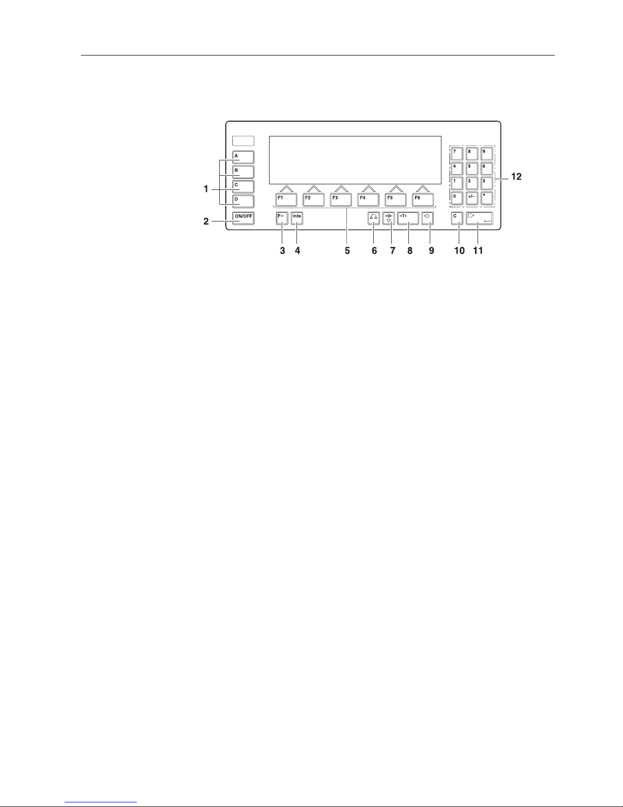
1.3.2 Keypad
1 CODE A ... CODE D keys – enter identification data
2 ON/OFF – On/Off key
3 FUNCTION CHANGE key – display additional functions
when entering weight values: switch over unit
4 INFO key – recall memory contents and system information
5 Function keys F1 … F6 – the current assignment is shown in the display above
the key
6 SCALE key – select scale
7 ZERO-SET key – set scale to zero, test scale
8 TARA key – tare scale
9 TARE SPECIFICATION key – enter known tare values numerically
10 CLEAR key – clear entries and values
11 ENTER key – accept and transfer data
12 Numeric keypad with decimal point and signs
Introduction and commissioning
6 Operating instructions and installation information 22004109D 04/10
ID7-Base
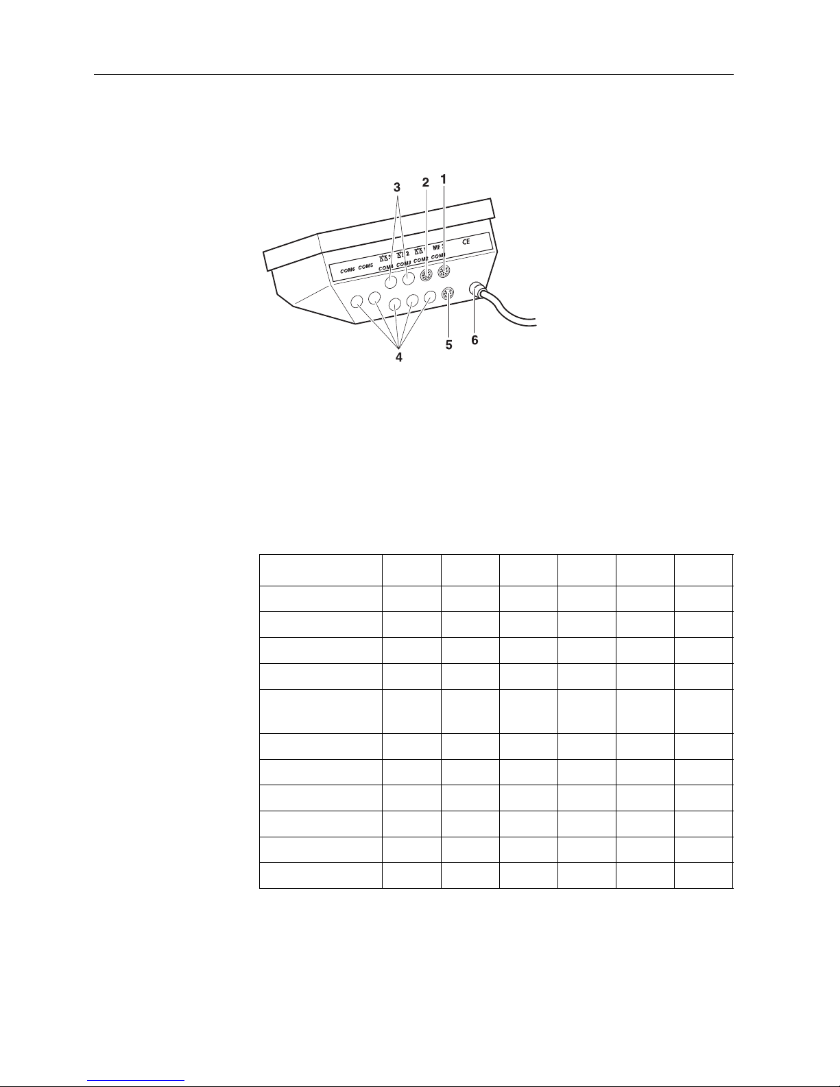
1.3.3 Connections
1 Connection for the external MFII keypad
2 Connection for weighing platform 1
3 Optional connections for weighing platforms 2 and 3
4 5 optional interface connections
5 Standard RS232 interface
6 Power supply
Possible assignments for serial interfaces
Interface COM1 COM2 COM3 COM4 COM5 COM6
CL20mA-ID7 –xxxxx
RS232-ID7 xxxxxx
RS422-ID7 ––––xx
RS485-ID7 ––––xx
RS485-ID7 with
relay box 8-ID7
––––xx
4 I/O-ID7 ––––xx
Analog Output-ID7 ––––xx
Alibi Memory-ID7–xxxxx
Ethernet-ID7–xxxxx
Profibus-DP-ID7–xxxxx
WLAN-ID7 –xxxxx
Introduction and commissioning
Operating instructions and installation information 22004109D 04/10 7
ID7-Base
Notes
• COM1 is permanently equipped with the serial interface RS232-ID7 as standard.
• Only one Alibi Memory ID7 can be installed. It has no additional external
connection, and internally it occupies the space of a data port COM2 ... COM6.
Alibi Memory ID7 is installed as COM4 at the factory.
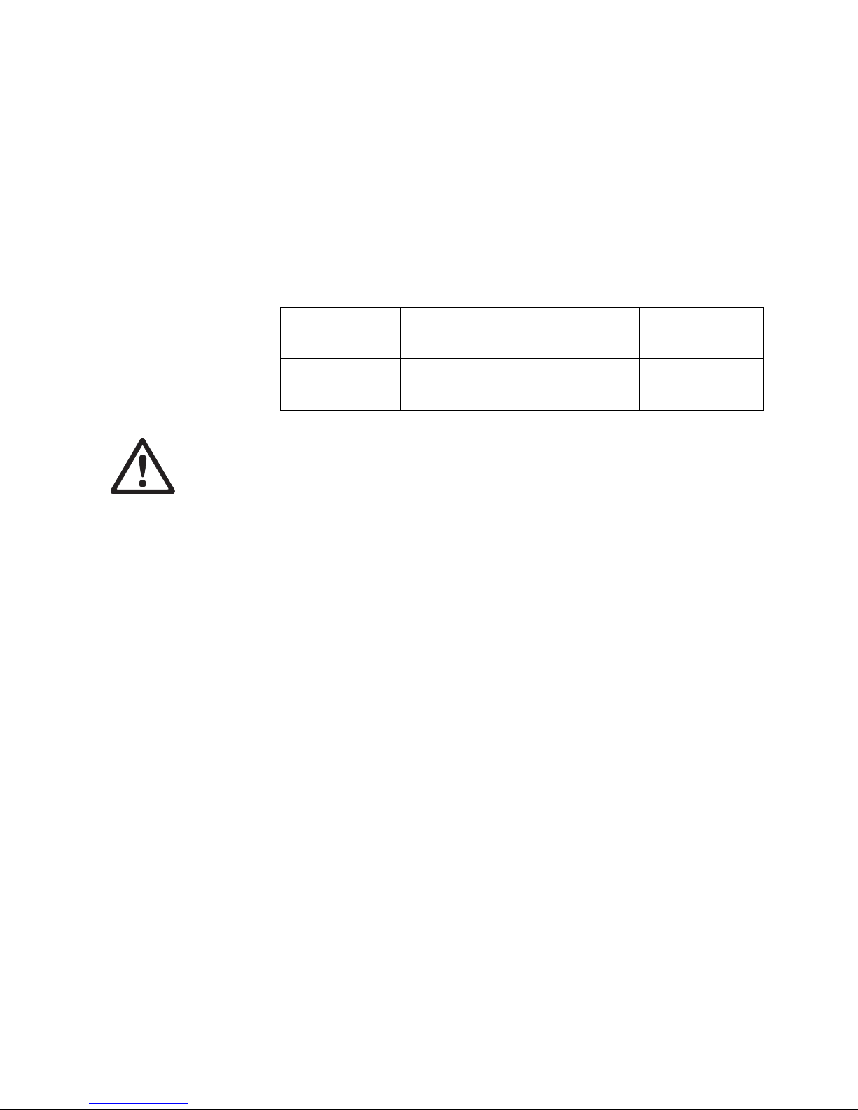
• A maximum of 4 cards Analog Scale-ID7, Ethernet-ID7, Profibus-DP-ID7, WLAN-ID7
or Alibi Memory-ID7 can be installed in the ID7-Base. The following combinations
are possible:
CAUTION
➜ Cover unused connection sockets with protective caps to protect the socket
contacts from moisture and dirt.
1.4 Commissioning
1.4.1 Connect weighing platforms of the series D, F, K, N, Spider ID and AWU3/6
1. Set up weighing platform, see installation instructions of weighing platform.
2. Route weighing platform cable to weighing terminal.
3. Plug in weighing platform connector on weighing terminal.
1.4.2 Connect scales of the series B, G, R and DigiTOL
Precision scales of the series B, G and R can be connected to the ID7-Base weighing
terminal with the LC-IDNet B or LC-IDNet R/G connection set.
To connect DigiTOL scales, the GD17 connection set is required.
1. Set up scale, see operating instructions of scale.
2. Connect appropriate connection set to scale.
3. Route cable of connection set to weighing terminal and plug in.
1.4.3 Commissioning with several weighing platforms
➜ To start up the ID7-Base weighing terminal with several weighing platforms,
please contact METTLER TOLEDO Service.
Analog Scale-ID7
Ethernet-ID7
or WLAN-ID7
Profibus-DP-ID7 Alibi Memory-ID7
211 –
1111

Introduction and commissioning
8 Operating instructions and installation information 22004109D 04/10
ID7-Base
1.4.4 Connect ID7-Base to network
CAUTION
The ID7-Base weighing terminal only functions properly with mains voltages of
100 V to 240 V.
➜ Make sure that the mains voltage at the installation location lies within this
range.
➜ Make sure that the mains outlet is grounded and easily accessible.
Connecting
➜ Plug mains plug of ID7-Base into a mains outlet.
In the factory setting the display briefly shows METTLER TOLEDO ID7 and the
versions of the installed components; then the weight display appears.
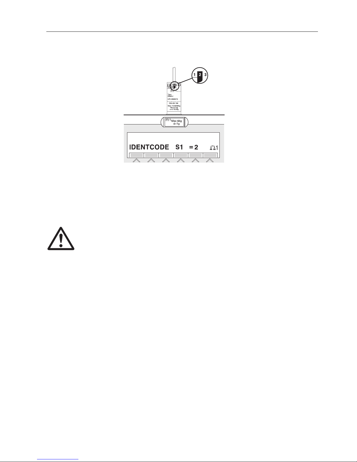
1.4.5 Marking and sealing of certified weighing platforms
ID code With the ID code it can be checked whether certified weighing platforms have been
tampered with since the last certification. The ID code can be displayed on the
terminal at any time, see section 3.10.
During certification the currently displayed ID code is recorded and sealed.
During each change to the configuration the displayed ID code increases. It then no
longer matches the sealed ID code; the certification is not longer valid.
Certification To mark and certify your weighing system, please contact METTLER TOLEDO Service
or your local board of weights and measures.
Check certification
1. Display ID code, see section 3.10; press ZERO-SET key until IDENTCODE = ...
is displayed.
No value is shown for noncertified weighing platforms, but instead:
IDENTCODE ===.
2. Compare ID code displayed with sealed ID code on ID card.
The certification of the weighing system is only valid when both values are
identical.
Introduction and commissioning
Operating instructions and installation information 22004109D 04/10 9
ID7-Base
3. Press ZERO-SET key again.
The connected weighing platform is checked. The display shows CHECK SCALE
and after the test is completed SCALE IS OK.
Then the ID7-Base automatically returns to normal operation.
1.5 Cleaning
DANGER OF SHOCK
➜ Do not open ID7-Base weighing terminal to clean.
CAUTION
➜ Make sure that unused connection sockets are covered with protective caps to
protect the socket contacts from moisture and dirt.
➜ Do not use high-pressure cleaners.
Cleaning
➜ Wipe off ID7-Base weighing terminal with a commercially available glass or
plastic cleaner.

Basic functions
10 Operating instructions and installation information 22004109D 04/10
ID7-Base
2 Basic functions
2.1 Switching on and off
Switch on from the standby mode
➜ Press 0N/OFF key.
The display shows a weight value based on the last tare value and zero point.
Switch on with restart
1. Relieve weighing platform.
2. Press ON/OFF key and hold down until METTLER TOLEDO ID7 (factory setting) or
text you have specified appears in display.
Then weight value 0.000 kg appears.
The weighing platform is restarted.
Note
The text which appears during switch-on with a restart is saved in the text
memory 20, see section 4.3.2.
Switch off
➜ Press ON/OFF key.
The display goes out and the ID7-Base weighing terminal is in the standby
mode. The zero point and tare value remain saved.
2.2 Setting to zero
Setting to zero corrects the influence of minor dirt on the load plate.
In the case of excessive dirt which cannot be compensated by setting to zero, the
display shows OUT OF RANGE.
Manual zero set
1. Relieve weighing platform.
2. Press ZERO-SET key.
The display shows 0.000 kg.
Automatic zero set
On certified weighing platforms the zero point of the weighing platform is automatically corrected when the weighing platform is relieved.
The automatic zero set can be switched off in the master mode on noncertified
weighing platforms.

Basic functions
Operating instructions and installation information 22004109D 04/10 11
ID7-Base
2.3 Taring
2.3.1 Manual taring
1. Place empty container on scale.
2. Press TARE key.
The tare weight is saved and the weight display set to zero.
The display shows the NET symbol.
Notes
• When the weighing platform is relieved, the saved tare weight is displayed with a
negative sign.
• The weighing platform only saves one tare value.
2.3.2 Automatic taring
Prerequisite
AUTOTARA ON must be set in the master mode, see section 4.4.
➜ Place empty container on scale.
The container weight is automatically saved and the weight display set to zero.
The display shows the NET symbol.
Note
When the weighing platform is relieved, the saved tare weight is cleared.
2.3.3 Specify tare weight
Enter numerically 1. Press TARE SPECIFICATION key.
2. Enter tare weight (container weight) and confirm with ENTER.
When weighing platform is relieved, the entered tare weight is displayed with a
negative sign.
Note
With the FUNCTION CHANGE key you can select the weight unit for entering the tare
weight.
Correct entry ➜ Clear the entry character by character with the CLEAR key and repeat correctly.

Basic functions
12 Operating instructions and installation information 22004109D 04/10
ID7-Base
Copy tare
constant
The ID7-Base has 999 tare memories for frequently used tare weights programmed
in the master mode.
1. Enter memory number: 1… 999.
2. Press TARE SPECIFICATION key.
The display shows the NET symbol and the net weight based on the recalled tare
weight.
2.3.4 Recall currently saved tare weight
The saved tare weight can be recalled at any time.
➜ Enter INFO, TARE SPECIFICATION key sequence.
The saved tare weight is displayed.
2.3.5 Clear tare weight
➜ Relieve weighing platform and tare.
– or –
➜ Specify tare weight 0.
– or –
➜ Enter TARE SPECIFICATION, CLEAR key sequence.
2.4 Weighing
Weighing without taring
➜ Lay weighing sample on weighing platform.
Gross weight (total weight) is displayed.
Weighing with taring
1. Place the empty container on the weighing platform and tare.
2. Pour in weighing sample.
The display shows the net weight and the NET symbol.
Weighing with tare specification
1. Place filled container on weighing platform.
The display shows the gross weight (total weight).
2. Specify tare weight or recall tare memory.
The display shows the net weight (container content) and the NET symbol.
Note
If a multi-range weighing platform is chosen, a display for the currently active range
appears above the scale symbol.

Basic functions
Operating instructions and installation information 22004109D 04/10 13
ID7-Base
2.5 Switch over weighing platform
Up to 3 weighing platforms can be connected to the ID7-Base.
The weighing platform currently selected is shown on the terminal.
➜ Press SCALE key.
The next weighing platform is selected.
– or –
➜ Enter number of weighing platform and press SCALE key.
The desired weighing platform is selected.
Additional functions
14 Operating instructions and installation information 22004109D 04/10
ID7-Base
3 Additional functions
The assignment of the 6 function keys of the ID7-Base weighing terminal differs
depending on the weighing task. The current assignment is shown above the function
keys.
With the FUNCTION CHANGE key it is possible to switch over to other function key
assignments.
Independent of the application software, the ID7-Base has the following additional
functions:
If at least one dynamic switching point is configured in the master mode (see page
51), the second row of function keys is given the following assignment:
3.1 Weighing with the DeltaTrac
The DeltaTrac is an analog display which makes it easier to read the weighing
results.
In the master mode you can select how the DeltaTrac is displayed for the various
weighing tasks FILLING, CLASSIFYING or CHECKWEIGHING.
Note
• With the DeltaTrac signals you can also control lamps, flaps or valves, see section
4.5.4.
DELT DYN UNIT X 10 GROSS MODE
Weighing
with the
DeltaTrac,
see 3.1
Dynamic
weighing,
see 3.2
Change
weight unit,
see 3.3
Increase resolution, see
3.4. This key
is not assigned when
the control
mode is continually
switched on.
Display
gross weight,
see 3.5
Activate
master mode,
see
Chapter 4
MULT-TARE ADD-TARE SANDWICH-T
Multiplicative tare function,
see 3.7
Additive tare function, see 3.8 Sandwich tare, see 3.9
SETP MUL-T ADD-T SW-T
Set dynamic
set points,
see 3.6
Multiplicative
tare function,
see 3.7
Additive tare
function,
see 3.8
Sandwich
tare, see 3.9
Additional functions
Operating instructions and installation information 22004109D 04/10 15
ID7-Base
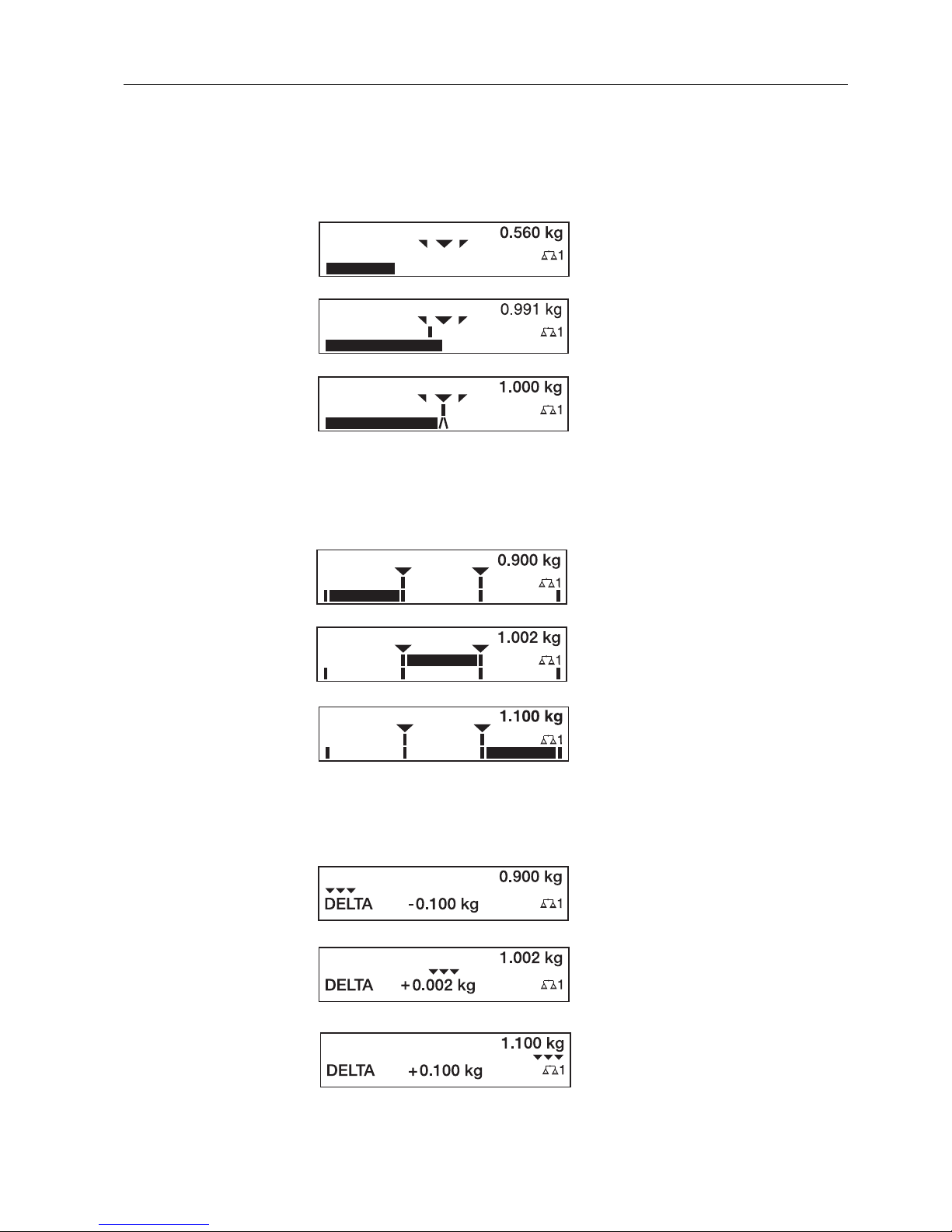
Application
FILLING
For weighing-in to a target weight with tolerance monitoring.
Application
CLASSIFYING
To evaluate test samples as OKAY, TOO LIGHT or TOO HEAVY, based on a target
weight and specified +/– tolerances.
Application
CHECKWEIGHING
For determining the difference between the target and actual weight.
Example: Target weight = 1.000 kg, tolerance = 1 %
Target weight not reached yet
Weight within the tolerance
Target weight reached exactly
Example: Target weight = 1.000 kg, tolerance = 1 %
TOO LIGHT
Weight below the tolerance
OKAY
Weight within the tolerance
TOO HEAVY
Weight above the tolerance
Example: Target weight = 1.000 kg, tolerance = 1 %
Weight below the tolerance
Difference: –0.100 kg
Weight within the tolerance
Difference: +0.002 kg
Weight above the tolerance
Difference: +0.100 kg

Additional functions
16 Operating instructions and installation information 22004109D 04/10
ID7-Base
3.1.1 Preset DeltaTrac target values
Enter numerically 1. Press DELT key.
2. Enter target weight and confirm with ENTER.
3. Enter tolerance in % of target weight and confirm with ENTER.
Note
With the FUNCTION CHANGE key you can select the weight unit for entering the
DeltaTrac target values.
Correct entry ➜ With the CLEAR key the entry is corrected character by character.
Copy constants The ID7-Base weighing terminal has 999 DeltaTrac memories for frequently used
target values and tolerances, which are programmed in the master mode.
1. Enter number of DeltaTrac memory: 1 … 999.
2. Press DELT key.
Reference sample 1. Press DELT key.
2. Lay sample on weighing platform and confirm with SCALE key.
3. Only for FILLING and CLASSIFYING: Enter tolerance and confirm with ENTER.
4. Remove sample from weighing platform.
Limits Minimum target value 10 Digit, can be adjusted in mastermode, see section 4.3
Maximum target value configured maximum load
Minimum tolerance 1 Digit
Maximum tolerance 10 % for the applications FILLING, CHECKWEIGHING
50 % for the application CLASSIFYING
Note
If the limits are not observed, a message appears in the display, e.g. MIN-DEL = ...,
for too small a target value.
Clear DeltaTrac target
value
➜ Press DELT CLEAR key sequence.
DELTA CLEARED appears briefly in the display, then the weight is shown.

Additional functions
Operating instructions and installation information 22004109D 04/10 17
ID7-Base
3.2 Dynamic weighing
With the dynamic weighing function you can weigh restless weighing samples, e.g.
live animals. To do this, specify the number of weighing cycles for which the mean
weight value is to be taken.
1. Set container on the weighing platform.
2. Tare weighing platform.
3. Place weighing sample in container.
4. Press DYN key and enter number of weighing cycles.
Possible values: 1 … 255.
5. Start dynamic weighing with ENTER key.
6. After cycle time has expired, center line of display shows:
RESULT x.xxxx kg.
This display is retained until the next weighing is started or until it is cleared.
Delete result ➜ Press CLEAR key.
Notes
• Dynamic weighing results are automatically printed when AUTO PRINT is set in the
master mode, see section 4.3.2.
• During dynamic weighing it is not possible to display the weight value BIG
WEIGHT DISPLAY, which fills the entire display.
• Dynamic weighing can also be started with the interface command AW016..., see
section 6.2.
3.3 Change weight unit
If an additional, second weight unit is configured in the master mode, it is possible to
switch back and forth between the two weight units.
➜ Press UNIT key.
The weight value is shown in the second unit.
Note
Possible second weight units are: g, kg, lb, oz, ozt, dwt.

Additional functions
18 Operating instructions and installation information 22004109D 04/10
ID7-Base
3.4 Working in a higher resolution
Depending on the setting of the master mode block CONTROL MODE (see page 32),
the weight value can be displayed in a higher resolution continuously or when called.
Weight values in a higher resolution are marked with a *.
Displaying weight values in higher resolution
➜ Press X 10 key.
The weight value is displayed in at least a 10x higher resolution.
The higher resolution is displayed until the X 10 key is pressed again.
Note
With certified weighing platforms, the weight value only appears in a higher
resolution as long as the X 10 key is pressed.
3.5 Display gross weight
The gross weight can only be displayed when a tare weight has been saved.
➜ Press GROSS key and hold down.
The gross weight is displayed.
3.6 Specifying dynamic set points
Conditions
• 4 I/O-ID7 interface or 8-ID7 relay box connected.
• SETPOINT MODE ON and at least one dynamic set point is configured in the
master mode.
Use If the specified set point values are exceeded or dropped below, digital outputs are
set, e.g. for controlling lamps, flaps, valves etc.
Dynamic set points can be set for each weighing procedure individually.
The set points are retained until they are overwritten with a new value or deleted.
Specifying set points
1. Press the SETP key; the entry prompt for the first dynamic set point appears.
2. Enter the desired weight value and confirm with ENTER.
3. If additional dynamic set points are configured, the entry prompt appears for the
next dynamic set point.
4. Enter the desired weight value and confirm with ENTER.
5. Repeat the procedure until all set points have been entered.
Deleting set points
➜ Press the SETP key and delete the value with the CLEAR key.
Additional functions
Operating instructions and installation information 22004109D 04/10 19
ID7-Base
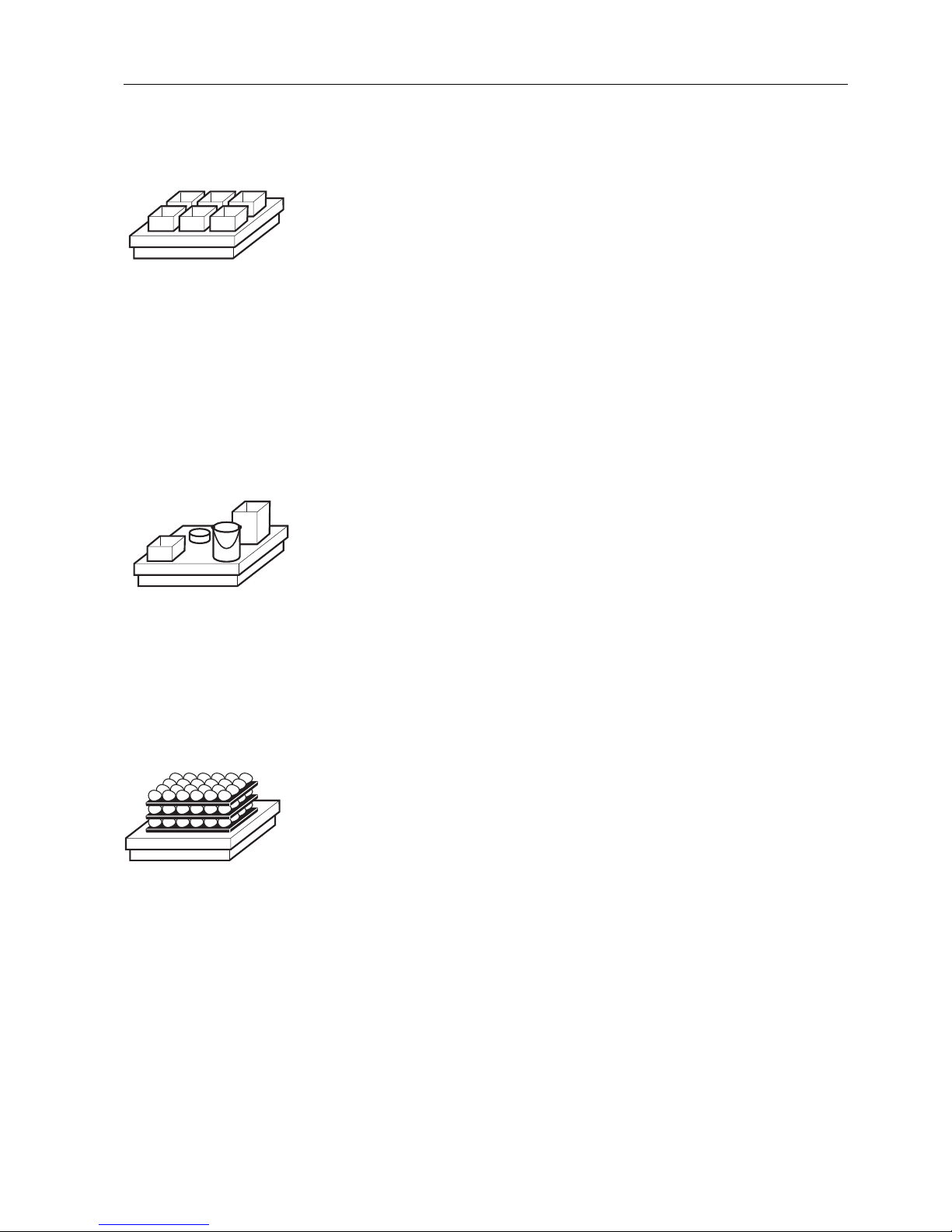
3.7 Multiplicative tare function
The multiplicative tare function is particularly suitable when pallets with identical
containers are filled. If the number of containers and tare of the individual container
are known, the ID7-Base weighing terminal calculates the total tare.
1. Press MULT TARE key.
2. Enter known tare weight of individual container and confirm with ENTER.
3. Enter number of containers and confirm with ENTER.
When the weighing platform is relieved, the total tare value is shown in the
display with a negative sign.
Note
With the FUNCTION CHANGE key you can select the weight unit for entering the tare
weight.
3.8 Additive tare function
With the additive tare function you can subtract the tare of additional containers with
a know tare weight for related weighings, e.g. if containers with different weights are
filled on one pallet.
1. Place container on scale and press ADD TARE key.
2. Enter known tare weight and confirm with ENTER.
The total net weight appears in the weight display.
Note
With the FUNCTION CHANGE key you can select the weight unit for entering the tare
weight.
3.9 Sandwich tare
With the sandwich tare function you can detect additional tare weights for related
weighings without loosing the total gross and total net.
Example
In production or shipping boxes are laid between individual layers in the transport
container. The weight of these boxes can be subtracted with this function.
1. Press SANDWICH-T key.
2. Place sandwich tare, e.g. box, on scale and confirm with ENTER.
The net weight is retained.

Additional functions
20 Operating instructions and installation information 22004109D 04/10
ID7-Base
3.10 Display ID code and test weighing platform
Each time the weighing platform configuration is changed the ID code counter is
increased by 1. On certified weighing platforms the displayed ID code must match
the ID code on the ID code sticker, otherwise the calibration is no longer valid.
Display ID code
➜ Press ZERO-SET key and hold until IDENTCODE = ... appears in the display and
press again.
Test weighing platform
➜ Press ZERO-SET key again.
The connected weighing platform is checked. The display shows CHECK SCALE
and then SCALE IS OK after completing the test.
Note
If weighing platform is defective, display shows SCALE ERROR.
3.11 Identifications
The ID7-Base weighing terminal is equipped with 4 identification data memories for
storing identification data Code A … Code D.
The memories have a name, e.g. Article No., and a content which identifies the
current weighing, e.g. 1234567.
The memories are named in the master mode, and the names can be noted on the
keyboard. When the CODE keys are pressed, the name appears in the display.
Identification data Code A … Code D can be entered or recalled for each weighing
and are printed immediately.
3.11.1 Enter identification
An identification may contain a maximum of 20 characters.
Enter
numerical identification
1. Press one of the keys CODE A … CODE D.
2. Enter identification data Code A … Code D via the numeric keypad and confirm
with ENTER.

Additional functions
Operating instructions and installation information 22004109D 04/10 21
ID7-Base
Enter
alphanumeric
identification
1. Press one of the keys CODE A … CODE D.
The functions keys are given the following assignment:
2. Select desired group of letters, e. g. press KLMNO key.
3. Select desired letter.
The display changes again to the above selection.
4. Repeat entry in steps 2 and 3 for additional characters.
Note
Letters and numbers can be combined as desired.
Recall fixed text
memory
The ID7-Base weighing terminal is equipped with 999 memories for fixed texts which
can be programmed in the master mode and used as identifications.
1. Enter memory number: 1 ... 999.
2. Press a key CODE A … CODE D.
The saved fixed text is now assigned to the selected identification Code A …
Code D.
Other entry possibilities Identifications can also be entered with a barcode reader, see section 3.14, or with
an external keypad, see section 3.15.
3.11.2 Clear identifications
➜ Press desired key CODE A … CODE D and clear memory content with CLEAR key.
ABCDE FGHIJ KLMNO PQRST UVWXY Z/-()
Selection of
letters A to E
Selection of
letters F to J
Selection of
letters K to O
Selection of
letters P to T
Selection of
letters U to Y
Selection of
letter Z and
special
characters
Additional functions
22 Operating instructions and installation information 22004109D 04/10
ID7-Base
3.12 Recall information
On the ID7-Base weighing terminal memory contents and system information can be
recalled.
1. Press INFO key.
Then the following function key assignment appears:
2. Select desired information.
The information is displayed for the set DISPLAY DURATION, then the ID7-Base
changes to the weighing mode again.
Notes
• When several values are displayed, the ID7-Base automatically changes to the
next value after the set DISPLAY DURATION.
• With the CLEAR key it is possible to switch to the next value or back to the
weighing mode.
• When the GA46 printer is connected, the version numbers of the installed software
modules are automatically printed.
3.12.1 Recall memory
1. Press INFO key.
2. Enter number of memory and press DELT, TARA or TEXT key depending on
desired memory.
Recall name of CODE A … CODE D keys
1. Press INFO key.
2. Press one of the keys CODE A … CODE D.
The display shows the current Code.
DELT TARE TEXT ALIBI DATE VERS
Display
DeltaTrac
values
Display tare
weight
Display fixed
texts and
name of keys
CODE A …
CODE D
Recall content
of alibi
memory, see
section 2.1.
This selection
only appears
when Alibi
Memory-ID7
is installed.
Display date
and time
Display
version
numbers of
installed
software
modules

Additional functions
Operating instructions and installation information 22004109D 04/10 23
ID7-Base
3.13 Print or transfer data
If a printer or computer is connected, weighing results can be printed out or
transferred to the computer.
In the master mode you can set the following for this purpose:
• Data to be printed or transferred,
• Manual or automatic data transfer,
• Key which triggers printing or data transfer.
Factory setting
• Manual triggering with the ENTER key.
• The content of the display is transferred or printed.
3.14 Enter values with barcode reader
If you have connected a barcode reader to the ID7-Base weighing terminal, you can
make all required entries, such as identifications or target specifications, easily with
the barcode reader.
3.14.1 Read in any desired entries with the barcode reader
Example Read in identification Code A
1. Press CODE A key; the ID7-Base expects the entry of Code A.
2. Enter identification Code A with the barcode reader.
The identification read in appears in the display.
3. Confirm barcode entry with ENTER.
3.14.2 Read in a frequently used entry directly with the barcode reader
If your working procedure repeatedly requires the same entry, you can configure the
barcode reader in the master mode (see section 4.5.3) so that no additional keys
need to be pressed on the ID7-Base terminal for barcode entry.
Example Barcodes are automatically read in as Code A
If the working procedure requires the entry of Code A:
➜ Enter identification Code A with barcode reader.
The information read in appears in the display and is automatically processed by
ID7-Base as Code A.
Additional functions
24 Operating instructions and installation information 22004109D 04/10
ID7-Base
3.15 Working with external keypad
In addition to the alpha and numerical keys, the following additional scale functions
can also be operated with the external AK-MFII keypad.
Note
The language of your external keyboard can be set in the master mode block LAYOUT
EXT. KEYBOARD, see page 30.
Function for ID7-Base
External
keypad
Function for ID7-Base
External
keypad
Function key F1 F1 CODE A key Shift F1
Function key F2 F2 CODE B key Shift F2
Function key F3 F3 CODE C key Shift F3
Function key F4 F4 CODE D key Shift F4
Function key F5 F5
Function key F6 F6
FUNCTION CHANGE key F7
INFO key F8
SCALE key F9 SCALE key Shift F9
ZERO-SET key F10 ZERO-SET key Shift F10
TARE key F11 TARE key Shift F11
TARE SPECIFICATION key F12 TARE SPECIFICATION key Shift F12

Additional functions
Operating instructions and installation information 22004109D 04/10 25
ID7-Base
3.16 Working with a second display
An ID1 Plus, ID3s or another ID7-... weighing terminal can be connected to the
ID7-Base weighing terminal as a second display.
Conditions
• Interface CL 20mA-ID7 installed in passive operating mode (factory setting).
• AUTO-DIR setting selected in mastermode (see page 41).
• Weighing terminal is connected as second display with cable 00 504 511.
Operation possibilities on second display
The following functions are also possible on the second display:
• Set to zero
•Taring
ID7-... as second display
With ID7-... as a second display, the weight value fills the entire display (BIG
WEIGHT DISPLAY ON).
Settings in the master mode
26 Operating instructions and installation information 22004109D 04/10
ID7-Base
4 Settings in the master mode
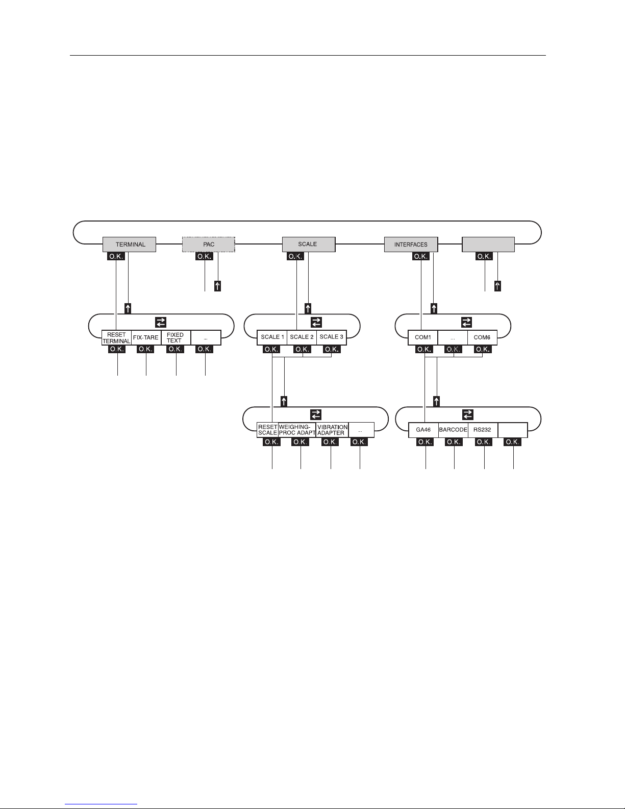
4.1 Overview of the master mode
In the master mode you adapt the ID7-Base weighing terminal to meet your needs.
Depending on the configuration, the master mode is divided into 4 or 5 master mode
blocks, which are in turn divided into further blocks.
TERMINAL For system settings, such as entering the date and time or loading permanent texts,
see section 4.3.2.
PAC To set application-specific parameters.
This block does not appear with ID7-Base.
SCALE To select one of the connected weighing platforms. For each selected weighing
platform the parameters are then set which concern the weight value, e. g. stability
detector, unit, etc., see section 4.4.
INTERFACES To select an interface. The communication parameters are then set for each interface,
see section 4.5.
SERVICE For configuring the weighing platform(s). On IDNet weighing platforms only for
METTLER TOLEDO service technicians.
SERVICE
Settings in the master mode
Operating instructions and installation information 22004109D 04/10 27
ID7-Base
4.2 Operating the master mode
4.2.1 Enter the master mode
1. Press MODE key.
If the current function key assignment does not contain MODE, change to the
assignment with MODE by repeatedly pressing the FUNCTION CHANGE key.
2. Enter personal code if configured.
The display shows the first master mode block TERMINAL.
4.2.2 Assignment of function keys in the master mode
In the master mode the function keys are assigned as follows:
➜ Select the function by pressing the function key.
Example ➜ Press the END key to exit the master mode and return to the normal mode.
When the function keys are otherwise allocated
➜ Press the key FUNCTION CHANGE until the function keys allocation displayed
above appears.
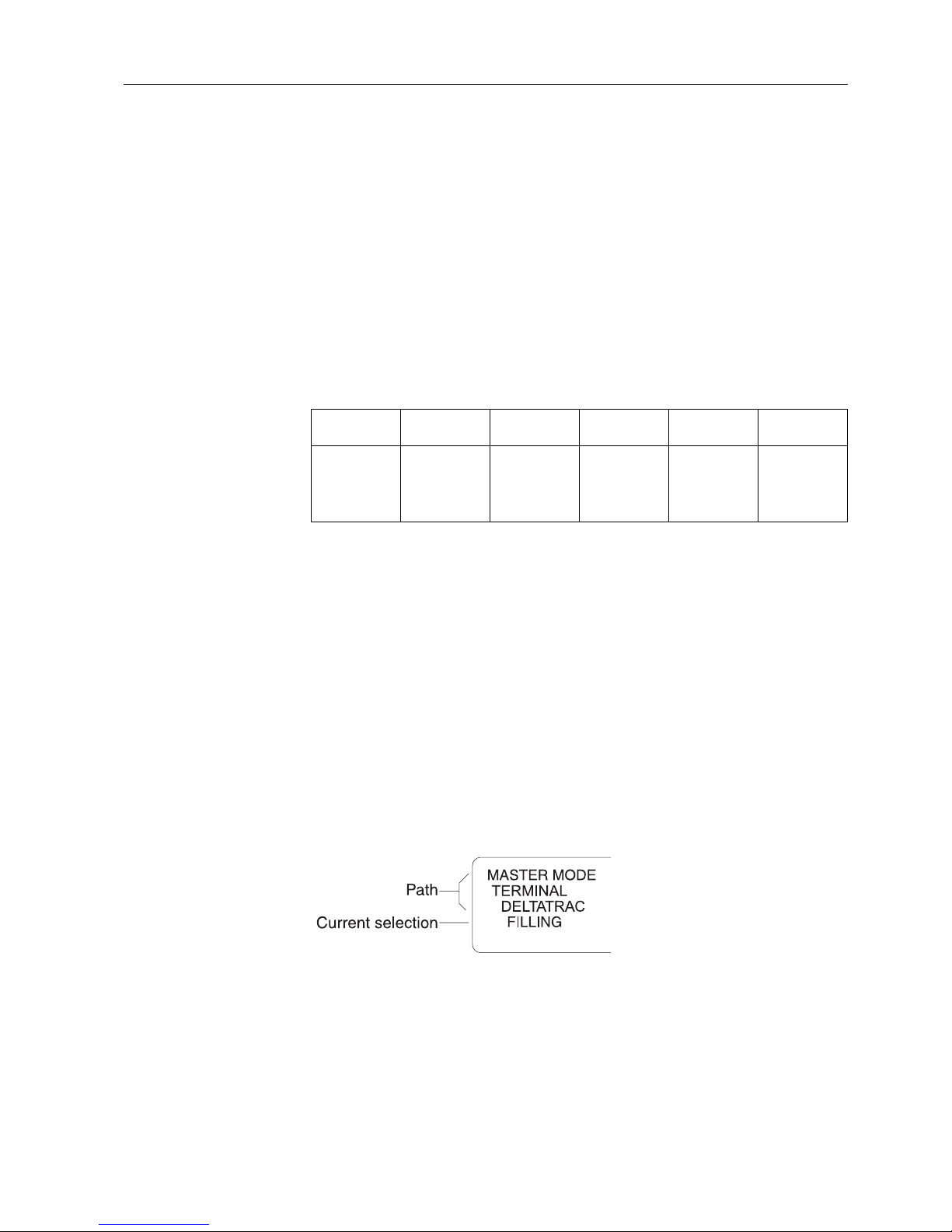
4.2.3 Orientation in the master mode
For improved orientation the display shows the last steps in the path of the current
master mode block.
Example The upper 3 lines of the display show the following path for selecting the DeltaTrac
application FILLING:
4.2.4 Entries in the master mode
The following basic rules apply to entries made in the master mode:
• Confirm (alpha)numeric entries with ENTER.
• Alphanumeric entries with the ID7-Base: see section 3.11.
• To accept the displayed value: Press ENTER key.
←→ ↑
END OK
Change to
previous
block within a
level
Change to next
block within a
level
Exit level and
return to
higher-level
block
Exit the
master mode
and return to
normal mode
Recall lowerlevel block or
confirm
selection
Settings in the master mode
28 Operating instructions and installation information 22004109D 04/10
ID7-Base
4.2.5 Emergency entrance into the master mode
If a personal code has been assigned for entering the master mode and you have
forgotten your code, you can still enter the master mode:
➜ Enter the character sequence C, L, E, A, R as your personal code.
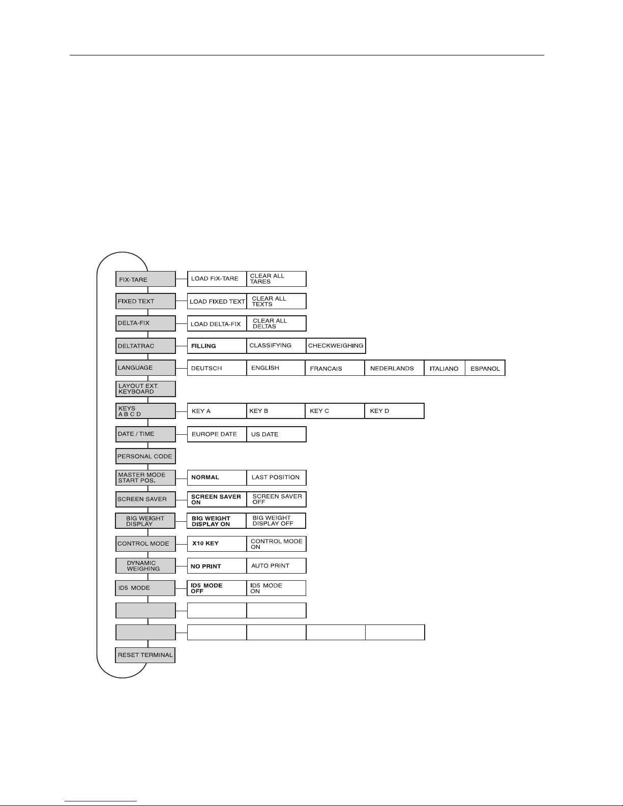
4.3 TERMINAL master mode block
4.3.1 Overview of the TERMINAL master mode block
In the TERMINAL master mode block you enter the following system settings:
Legend • Blocks highlighted in grey are described in detail in the following.
• Factory settings are printed in bold print.
ERROR
MESSAGES
INFO
MESSAGES
CODE A
DISPLAY
DURATION
ENTRY PROMPT
CODE B
CODE C CODE D
 Loading...