

Page 1
Thermal Analysis Excellence
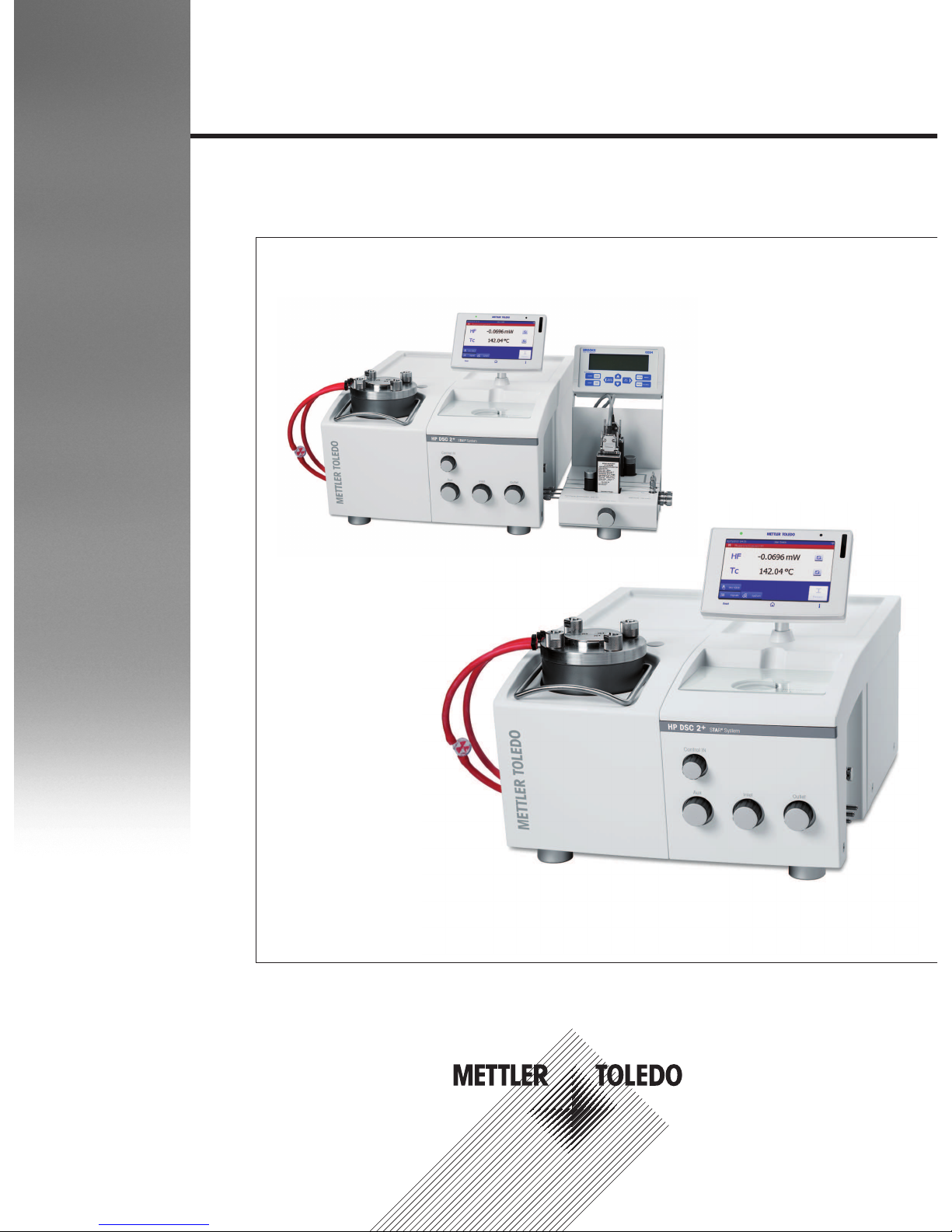
HP DSC 2+
Operating Instructions
Page 2

Page 3

Table of Contents
1 Introduction 3
1.1 About this document .................................................................................................... 3
1.2 Software versions required for your instrument................................................................. 3
1.3 Hardware options ........................................................................................................ 4
1.4 METTLER TOLEDO support and service ........................................................................... 4
2 Safety Information 5
2.1 Definition of signal words and warning symbols.............................................................. 5
2.2 General and instrument-specific safety information .......................................................... 5
2.2.1 General safety information.............................................................................. 5
2.2.1.1 Intended use........................................................................................... 5
2.2.1.2 Operating instructions.............................................................................. 6
2.2.1.3 Qualification of personnel......................................................................... 6
2.2.1.4 Protective clothing................................................................................... 6
2.2.1.5 General laboratory safety.......................................................................... 6
2.2.2 Instrument-specific information ....................................................................... 6
2.2.2.1 Safety notes related to operation at high pressure........................................ 6
2.2.2.2 Measures for your protection..................................................................... 7
2.2.2.3 Measures for operational safety................................................................. 9
2.2.2.4 Safety notes related to operation with explosive or flammable gases ............. 10
2.2.2.5 Precautions to minimize risks when using explosive or flammable gases ...... 10
2.2.2.6 Special safety notes on using hydrogen ..................................................... 11
2.2.2.7 Explosive limits....................................................................................... 11
2.2.2.8 FCC rules and the radio interference regulations .......................................... 11
2.2.3 Information on the cryostat............................................................................. 11
2.3 Warning symbol on the instrument ................................................................................ 12
3 Design and Function 13
3.1 Overview of the HP DSC module.................................................................................... 13
3.2 Connections on the rear panel....................................................................................... 14
3.3 The measuring cell....................................................................................................... 15
3.3.1 Cross section of the measuring cell ................................................................. 15
3.3.2 DSC sensors................................................................................................. 16
3.4 The cryostat ................................................................................................................ 16
3.5 SmartSens terminal...................................................................................................... 17
3.5.1 Overview of the SmartSens terminal................................................................. 17
3.5.2 The touch screen........................................................................................... 18
3.5.3 State indicator and experiment stages.............................................................. 20
3.6 Stages of an experiment ............................................................................................... 22
4 Installation and Putting into Operation 25
5 Operation 27
5.1 Workflow for experiments.............................................................................................. 27
5.2 Preparing the HP DSC module for experiments ................................................................ 27
5.2.1 Hints before you start an experiment................................................................ 27
5.2.2 Crucibles – without lid or with perforated lid ..................................................... 28
5.2.3 Performing a leak test.................................................................................... 28
5.3 Performing an experiment............................................................................................. 28
5.3.1 Loading the sample crucible into the measuring cell ......................................... 28
5.3.2 Starting the experiment .................................................................................. 30
5.3.3 Removing the sample and switching off the instrument...................................... 31
5.4 Terminating an experiment............................................................................................ 32
5.5 Using the SmartSens terminal........................................................................................ 33
5.5.1 Using the keys and the SmartSens sensor ........................................................ 33
Table of Contents 1Thermal Analysis Excellence
Page 4

5.5.2 Entering commands on the DSC module.......................................................... 34
5.5.2.1 Confirming an experiment stage................................................................ 34
5.5.2.2 Skipping an experiment stage................................................................... 34
5.5.2.3 Terminating an experiment ....................................................................... 34
5.5.2.4 Switching between standby and power save states...................................... 35
5.5.2.5 Starting experiments with One Click™ buttons ............................................ 35
6 Maintenance 37
7 Troubleshooting 39
7.1 Malfunctions ............................................................................................................... 39
7.2 Error messages ........................................................................................................... 39
7.3 List of error messages .................................................................................................. 40
8 Technical Data 43
9 Accessories and Spare Parts 45
Index 47
Table of Contents2 Thermal Analysis Excellence
Page 5

Introduction 3Thermal Analysis Excellence
1 Introduction
Thank you for purchasing this innovative METTLER TOLEDO instrument.
The HP DSC2+ is a measuring instrument for differential scanning calorimetry under pressure. It is part of
the METTLER TOLEDO system.
1.1 About this document
Operating Instructions and Reference Manual
These operating instructions contain the most important operational information for your instrument.
Additional information can be found in the reference manual, which can be downloaded here:
http://swupdateamc.mt.com/
To obtain these operating instructions in other languages, please contact your METLLER TOLEDO represen-
tative.
Product versions
This document refers to the HPDSC2+. This product name is only used where necessary. Where appropriate, the term "HP DSC module" is used for convenience.
Conventions and symbols used in this document
Buttons on the display are indicated by bold text, for example One Click.
Keys on the instrument are indicated by bold text in square brackets, for example [Reset].
The following symbols are used for procedures requiring user interaction:
prerequisites
1, 2, 3 ... steps
results
1.2 Software versions required for your instrument
Software
The HPDSC2+ can only be operated in conjunction with the Software from METTLER TOLEDO which
is installed on a PC. There is no stand-alone mode.
You require version 14.00 or later of the Software to operate the HPDSC2+.
References to the Software are included in certain parts of this document.
Firmware
These operating instructions refer to instruments running version 1.00 of the firmware.
The firmware version of your instrument is displayed in the System info dialog on the SmartSens terminal.
Page 6

Introduction4 Thermal Analysis Excellence
1.3 Hardware options
The instrument has a modular design. Each instrument can be individually configured and adapted to your
own particular requirements and applications.
If your requirements change, you can expand the module later on with additional options.
The following hardware options are available:
• PC 10: Used to automatically regulate and display the pressure and the gas flow in the measuring cell.
• Switched Line Socket: Allows the cryostat to be switched on and off under program control.
• Power Switch: Increases the available power for the cryostat.
• Peripheral Options Board: Required for synchronizing and triggering external devices.
• Hardware options for hyphenated techniques
– Microscopy Kit for HPDSC: Useful for visually identifying thermal events.
– Chemiluminescence Kit for HPDSC: Useful for identifying thermal events in the form of light
emission.
Note
For information about the hardware options above, see the Reference Manual, which can be downloaded
here: http://swupdateamc.mt.com/
1.4 METTLER TOLEDO support and service
METTLER TOLEDO offers you valuable support and services that help you optimally use your instruments:
http://www.mt.com/ta-services
Training
• Live Webinars
http://www.mt.com/ta-webinars
• On Demand Webinars
http://www.mt.com/ta-ondemand
• E-learning
http://www.mt.com/ta-etraining
• In-class Training
http://www.mt.com/ta-training
• Technical Videos
http://www.mt.com/ta-videos
Applications
• UserComs
http://www.mt.com/ta-usercoms
• App
http://www.mt.com/ta-app
• Applications Handbooks
http://www.mt.com/ta-handbooks
• Applications Database
http://www.mt.com/ta-applications
Service News
• Service and Support
http://www.mt.com/ta-service
• Good Thermal Analysis Practice™
http://www.mt.com/gtap
• Promotions
http://www.mt.com/ta-promotions
• TA News
http://www.mt.com/ta-news
Page 7

Safety Information 5Thermal Analysis Excellence
2 Safety Information
2.1 Definition of signal words and warning symbols
Safety notes are indicated by signal words and warning symbols and contain warnings and information
about safety issues. Ignoring safety notes can lead to personal injury, damage to the instrument,
malfunctions and erroneous results.
Signal Words
WARNING
for a hazardous situation with medium risk, possibly resulting in severe
injuries or death if not avoided.
CAUTION
for a hazardous situation with low risk, resulting in damage to the device
or the property or in loss of data or minor or medium injuries if not
avoided.
Attention
(no symbol)
for important information about the product.
Note
(no symbol)
for useful information about the product.
Safety notes are marked with warning triangles. The following symbols depict safety issues and warnings.
Ignoring the safety notes may lead to personal injury, damage to the instrument, malfunctions and false
results.
In general, please follow the lab safety guidelines as prescribed by your facility in order to avoid injury to
yourself or others.
General hazard Risk of electrical shock Heavy load Risk of explosion
Risk of burns Risk of fire Risk of uncontrolled
pressure release
Risk of poisoning
2.2 General and instrument-specific safety information
2.2.1 General safety information
The instrument is state of the art and complies with all recognized safety rules, however certain hazards
could arise. The instrument should only be operated in sound condition according to the operating
instructions. Do not open the instrument. It does not contain any parts which can be maintained, repaired or
replaced by the user. If you ever have problems with your instrument, contact your authorized METTLER
TOLEDO dealer or service representative.
2.2.1.1 Intended use
The HP DSC is intended for performing differential scanning calorimetry under pressure. All other uses are
deemed to be not intended without the written authorization of Mettler-Toledo AG, as is operation above and
beyond the limits of use stipulated by Mettler-Toledo AG.
For the limits of operation, see Technical Data.
Page 8
Safety Information6 Thermal Analysis Excellence
2.2.1.2 Operating instructions
The operating instructions must be read and understood. If the instrument is not used according to these
operating instructions, protection of the instrument may be impaired and METTLER TOLEDO assumes no
liability.
2.2.1.3 Qualification of personnel
The instrument should only be operated by qualified personnel. METTLER TOLEDO recommends appropriate
training and offers the respective seminars. The instrument must not be modified by reconstructive
measures compared to the factory original.
2.2.1.4 Protective clothing
It is advisable to wear protective clothing in the laboratory when working with the instrument.
A lab coat and suitable eye protection, such as safety spectacles, goggles or a face
shield should be worn.
Use appropriate gloves when handling chemicals or hazardous substances,
checking their integrity before use.
2.2.1.5 General laboratory safety
In general, the lab safety guidelines as prescribed by your facility must be followed in order to avoid injury
to yourself or others.
When using chemicals and solvents, the instructions of the manufacturer and the general lab safety rules
must be followed.
The responsible body has the responsibility for carrying out appropriate decontamination if hazardous
liquids are spilled on or inside the equipment.
2.2.2 Instrument-specific information
2.2.2.1 Safety notes related to operation at high pressure
CAUTION
Risk of uncontrolled pressure release.
You could be seriously injured by expelled parts.
− Never open the pressure cylinder when the system is under pressure.
Page 9
Safety Information 7Thermal Analysis Excellence
CAUTION
Risk of personnel injury or damage to the instrument due to operation at high
pressure.
1 Use the pressure measuring cell only for experiments for which it has been
manufactured in regard to maximum working pressure, corrosion resistance and
maximum temperature.
2 Make sure that the maximum working pressure of 10 MPa is not exceeded. The built-
in rupture disk responds at a pressure of 12.4 to 13.8 MPa.
3 When releasing flammable gases, make sure that the gas is vented according to the
laboratory safety regulations. Connect gas outlet and rupture disc to lines that lead off
the gas for proper disposal. Especially take measures to prevent the gas from flowing
into the instrument’s housing.
4 Never use corrosive gases for the pressure buildup or purging.
With time, corrosive gases attack and weaken the materials of the parts under
pressure. Material weakness can lead to an explosion or to leaks in the pressurized
measuring cell.
2.2.2.2 Measures for your protection
WARNING
Risk of electrical shock.
An electrical shock can be lethal.
1 Only use the original power supply cable provided with your instrument and plug it
into a grounded outlet.
2 Never open the instrument housing.
3 The power plug must be easily accessible.
WARNING
Risk of explosion if the instrument is used in an explosive atmosphere.
The housing of the instrument is not gas tight. An explosion caused by a spark can be
lethal.
− Never work in an environment subject to explosion hazards.
CAUTION
Risk of surfaces on the instrument heating up unduly after switching off the
cooling device prematurely.
You can burn yourself on hot surfaces on the measuring cell and in its surroundings.
Hot surfaces on the instrument can cause a fire.
− Never switch off the instrument or the cooling device when the temperature in the
furnace is above 100 °C.
CAUTION
Risk of damage from flammable samples.
Using flammable samples can cause damage to the instrument and in its vicinity.
− Take suitable measures to minimize any risk. See chapter "Operation" for more infor-
mation.
Page 10
Safety Information8 Thermal Analysis Excellence
CAUTION
Risk of explosion or fire due to explosive or flammable gas mixtures.
Explosion or fire from gas mixtures produced in the sample chamber can seriously injure
you.
1 Never use gases which may result in an explosive or a flammable gas mixture.
2 Never use explosive or flammable gases or gas mixtures to purge the measuring cell.
CAUTION
Risk of toxic or corrosive gases from samples that react or decompose.
You can be poisoned if you inhale toxic gases. Corrosive gases can damage the
measuring cell.
1 Place the instrument in a fume hood if you measure substances which form toxic
gases.
2 Purge the furnace and sample chamber with an inert gas after experiments in which
toxic or corrosive gases may have been produced. Do not use toxic or corrosive or
gas mixtures to purge the measuring cell.
CAUTION
Risk of injury due to heavy load.
You can injure yourself by carrying the instrument alone.
− Never try to carry the instrument alone. At least two people are needed to carry the
instrument.
CAUTION
Risk of hot surfaces.
You can burn yourself by touching parts of the measuring cell, furnace or the crucibles.
1 Always ensure cooling water flow (20 to 30 °C). The pressure cylinder and cover
would otherwise become so hot that you could burn yourself.
2 Allow the measuring cell to cool down to room temperature before performing any task
on the furnace.
3 Never place your fingers on or inside the furnace after an experiment.
4 Use tweezers to remove the furnace lid and crucibles.
Page 11

Safety Information 9Thermal Analysis Excellence
2.2.2.3 Measures for operational safety
CAUTION
Risk of false operation.
False operation can cause damage to or failure of the instrument.
1 Use only gas sources with a pressure regulator and a check valve. Never set the
pressure at the regulator higher than 10 MPa (maximum operating pressure). The gas
source may become contaminated in the absence of a check valve.
2 Never remove the pressure cylinder for measurements at ambient pressure.
3 Always set the pressure buildup using with the INLET valve.
4 Make sure that the CONTROL IN needle valve (for fine regulation) is not closed tightly
otherwise the needle valve could be damaged.
5 When using chemicals and solvents, comply with the instructions of the manufacturer
and the general lab safety rules.
6 The cooling device should also be on when the instrument is switched on.
7 The cooling fluid should not be colder than 15 ºC, otherwise condensation could
develop.
8 Use the instrument only indoors in a well-ventilated area, at altitudes of less than
3000m above sea level.
9 Avoid the following environmental influences:
- Powerful vibrations
- Direct sunlight
- Atmospheric humidity greater than 80% (non-condensing)
- Corrosive gas atmosphere
- Temperatures below 10 °C and above 31 °C
- Powerful electric or magnetic fields
10 Have the instrument serviced only by METTLER TOLEDO Service.
Note
The above list is not exhaustive; other items and precautions may have to be considered.
Page 12

Safety Information10 Thermal Analysis Excellence
2.2.2.4 Safety notes related to operation with explosive or flammable gases
CAUTION
Risk of explosion or fire if explosive or flammable gases are used.
You can be injured and the instrument can suffer damaged.
− If an application requires the use of explosive or flammable gases, you must be aware
of the risks and take appropriate safety precautions.
The HP DSC module is not designed for the use of explosive and flammable gases and the system is not
explosion-proof. METTLERTOLEDO excludes liability for all personal injury or damage resulting from using
explosive or flammable gases on the instrument.
See [Precautions to minimize risks when using explosive or flammable gases}10].
2.2.2.5 Precautions to minimize risks when using explosive or flammable gases
− Work in a room especially designed for working with explosive gases (alarm system, wall thickness
and so on).
− Put the instrument behind safety walls or operate it from a safe place. Make sure that no other persons
are in danger.
− Consider the risk that the flammable gas can accumulate in the instrument housing. If needed, purge the
housing with inert gases to avoid dangerous explosive concentrations.
− To release flammable gases, make sure that the gas is vented according to the laboratory safety
regulations. Especially take measures that the gas does not flow into the instrument housing.
− Check the tubing system for leaks before working with the flammable gas. For example use helium and
a corresponding gas leak detector. Check the measuring cell as well.
− Take measures to vent explosive and hot gas in case the rupture disk bursts. The instrument is fitted
with a rupture disk as a protection against overpressure. This disk may burst during the measurement
and release the explosive and hot gas.
− Before loading the cell with the flammable gas, fully replace the air by an inert gas so that explosive gas
or oxygen concentration is avoided. Pressurize to 1 MPa with nitrogen and release the gas at least three
times or purge long enough with the inert gas.
− Never open the furnace when it is hot, wait until the furnace temperature is below 30 °C.
Note
The above list is not exhaustive; other items and precautions may have to be considered.
Avoiding explosive mixtures
Loading and unloading the samples requires opening the pressure cylinder so that the surrounding ambient
gas, usually air, mixes with the furnace atmosphere: An explosive mixture can be created which will be
ignited by hot surfaces or sparks.
− Put the measuring cell in a glove box with an inert atmosphere to reduce the risk of having oxygen in
the measuring cell
- or Fill the furnace with nitrogen (or other inert gas) before opening the cell (pressurize to 1 MPa with
nitrogen and release the gas at least three times or purge long enough with the inert gas).
Risk of damaging the instrument
The flammable gas may chemically or physically alter some materials of the measuring cell, furnace,
crucible and the sample itself. This could damage the sensor or other parts of the instrument by forming
alloys or in other ways.
Page 13
Safety Information 11Thermal Analysis Excellence
2.2.2.6 Special safety notes on using hydrogen
If hydrogen has to be used to create a reducing atmosphere or to minimize the oxygen concentration, a
non-explosive mixture of ≤4% hydrogen in an inert gas is the preferred solution. The explosion limits of
hydrogen in air cover a very broad range from 4% to 77%. (The explosion limits of hydrogen and other
gases are indicated in the table below.)
The thermal conductivity of hydrogen is much higher than that of nitrogen. Hence, the surroundings of the
furnace may get much hotter than usual and the furnace may not reach the highest end temperatures
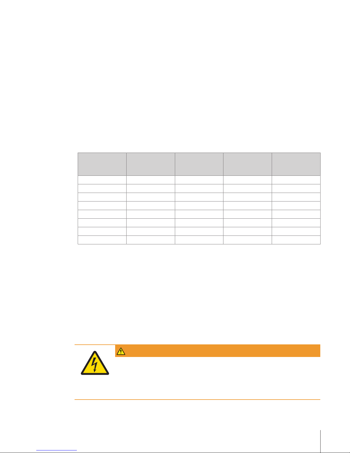
2.2.2.7 Explosive limits
Explosive limits, also called flammable or flammability limits, give the proportion of combustible gases in a
mixture, between which limits this mixture is flammable. Gas mixtures consisting of combustible, oxidizing,
and inert gases are only flammable under certain conditions. The lower flammable limit (LFL) (lower
explosive limit) describes the leanest mixture that is still flammable, i.e. the mixture with the smallest
fraction of combustible gas, while the upper flammable limit (UFL) (upper explosive limit) gives the richest
flammable mixture. Increasing the fraction of inert gases in a mixture raises the LFL and decreases UFL.
These limits depend on temperature and pressure and are given here for initial conditions of 0.1 MPa and
20°C. (Source: MERCK catalog 1990/91).
Gas Explosion limits
(LEL to UEL) in vol
%
Corrosive Flammable Toxic
Ammonia 15 - 28 x x x
Argon – – – –
Carbon dioxide – – – –
Ethylene 2.7 - 34 – x –
Helium – – – –
Hydrogen 4.0 - 75.6 – x –
Nitrogen – – – –
Oxygen – – – –
Note
The explosive limits values may vary slightly depending on your source of information.
2.2.2.8 FCC rules and the radio interference regulations
This equipment has been tested and found to comply with the limits for a Class A digital device, pursuant to
Part 15 of the FCC Rules. These limits are designed to provide reasonable protection against harmful interference when the equipment is operated in a commercial environment. This equipment generates, uses, and
can radiate radio frequency energy and, if not installed and used in accordance with the instruction manual,
may cause harmful interference to radio communications. Operation of this equipment in a residential area
is likely to cause harmful interference in which case the user will be required to correct the interference at his
own expense.
2.2.3 Information on the cryostat
WARNING
Risk of electrical shock.
An electrical shock can be lethal.
1 Always use a grounded power supply cable and plug it into a grounded outlet to
provide the cooling device with a grounded connection.
2 Never open the instrument housing.
Page 14
Safety Information12 Thermal Analysis Excellence
CAUTION
Risk of poisoning by toxic coolant liquids.
− When handling coolant liquids, comply with the instructions of the manufacturer of
these products and the general lab safety rules.
CAUTION
Risk of injury due to improperly secured coolant tube connections.
You could injure yourself if the coolant tubes slip off and the coolant used is toxic or
irritating to eyes and skin.
− Secure the tube connections on the cryostat with hose clamps.
2.3 Warning symbol on the instrument
The following warning symbol is applied on the instrument housing or components to warn users of
possible hazards.
This symbol warns that exposed surfaces can be hot to
the touch and can cause a skin burn.
Page 15
Design and Function 13Thermal Analysis Excellence
3 Design and Function
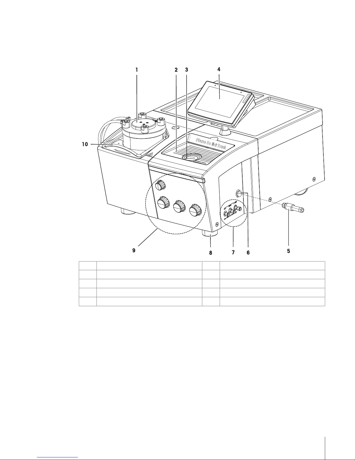
3.1 Overview of the HP DSC module
The figure below shows the basic configuration of the instrument.
1
Pressure cylinder with measuring cell
6
Rupture disc
2
Glass cover with note paper underneath
7
Gas connections
3
Pressure gauge
8
Screw feet (3 in total)
4
SmartSens terminal with touch screen
9
Control knobs for valves
5
Tube connection for venting toxic gases
10
Lifting bracket
The HP DSC module is a high pressure differential scanning calorimeter featuring a stainless steel pressure
cylinder which contains the DSC measuring cell. The pressure cylinder allows measurements up to a
maximum working pressure of 10 MPa and from room temperature up to 700°C.
The gas for building up pressure and purge and reactive gases for the measurement are connected to the
gas connections on the right side of the instrument. The gas flow is controlled by the control knobs on the
front side. A pressure gauge shows the pressure and a built-in rupture disc protects the cell against
excessive pressure.
The tube connection can be installed in place of the perforated bolt on the discharge valve if the gas needs
to be expelled in a controlled manner.
The pressure cylinder is opened and closed manually by removing or installing the pressure cylinder cover.
Page 16
Design and Function14 Thermal Analysis Excellence
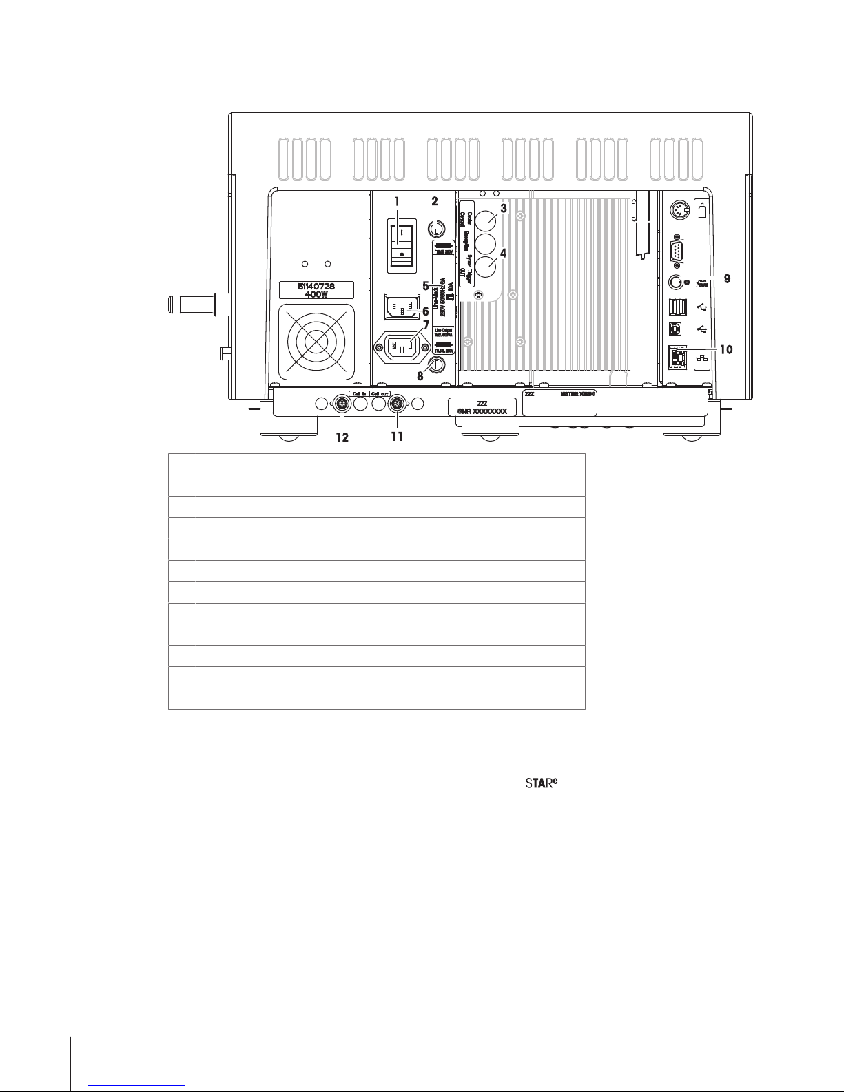
3.2 Connections on the rear panel
1
Main power switch
2
Fuse for electronics supply
3
unused
4
Connection for triggering and synchronization external devices
5
Rating plate
6
Power supply inlet socket
7
Line output socket
8
Fuse for line output socket
9
Connection for Power Switch option
10
Ethernet connection
11
Coolant outlet
12
Coolant inlet
Notes
• The line output socket is connected to the main power switch. If you switch off the instrument, you also
switch off any external device connected to the socket, for example the cooling device.
• The instrument is connected via the Ethernet connection to the Software PC.
Page 17

Design and Function 15Thermal Analysis Excellence
3.3 The measuring cell
3.3.1 Cross section of the measuring cell
The measuring cell essentially consists of the furnace, the furnace lid and the DSC sensor. Additional details
can be seen in the following schematic.
1
2
3
4
5
6
7
8
9
10
12
13
14
15
16
17
18
19
20
11
1
Nuts
11
DSC sensor tension spring
2
Pressure cylinder cover
12
Gas inlets
3
Alumina wool mat
13
Spring loaded furnace assembly
4
Furnace lid
14
Thermal resistor to heat sink
5
Crucibles on DSC sensor
15
Heating element
6
DSC sensor
16
pt100 temperature sensor
7
Inner cylinder
17
Silver furnace
8
Outer cylinder
18
Purge gas outlet
9
Pressure cylinder
19
O-ring of pressure cylinder cover
10
Cooling jacket
20
Cooling cover
An external cooling device must be connected providing a water flow rate of 20 L/h, with water temperatures
between 20 and 30ºC. See[The cryostat}16] for specific details.
Page 18

Design and Function16 Thermal Analysis Excellence
3.3.2 DSC sensors
The sensor type that best suits your type of application can be installed. There are two types of sensors
available for the HP DSC module: FRS 6+ and HSS 9+
The FRS6+ and HSS 9+ sensors feature two ears which hold the sensor in a fixed position in the furnace
and protect it against rotation. The ears prevent rotational movement of the sensor during operation.
The two sensor types can be interchanged with each other. For further details, see "Replacing the DSC
sensor" and "Technical Data".
FRS 6+ HSS 9+ Ears on sensor
3.4 The cryostat
You must use a cryostat for cooling the pressure cylinder.
The cryostat unit can be ordered separately from METTLER TOLEDO or directly from the manufacturer Huber.
We recommend the following type from Huber:
– Ministat 230-MT
Attention
The letters "MT" at the end of the type names indicate that these are units specially manufactured for
METTLER TOLEDO. Make sure to specify the correct type in your order.
For order numbers, see Accessories and Spare Parts.
For more information, visit the website at www.huber-online.com.
It is possible to use a cryostat from a different manufacturer. The following requirements for the cooling
system must be fulfilled to ensure that the high pressure cylinder and the measuring cell are cooled sufficiently and the temperature control system operates properly.
If the temperature monitoring system is operated outside of the permitted range, measurement errors can
occur.
• Required cooling power for operation
– 400 W
• Constancy of temperature
– +/- 1 °C
• Pump and suction capacities
– Pump capacity: 10 L/min at 0 bar
– Suction capacity: 250 mbar at 0L/min
Page 19

Design and Function 17Thermal Analysis Excellence
3.5 SmartSens terminal
The SmartSens terminal helps you to operate the HP DSC module. The main feature of the SmartSens
terminal is the touch screen. The touch screen not only displays information. It also allows you to enter
commands. This enables you for example to choose the information displayed on the screen, change
terminal settings or perform certain operations directly on the HP DSC module.
3.5.1 Overview of the SmartSens terminal
2
3
4
6
5
1
Name Explanation
1
Power indicator
light
• Is on when instrument is switched on.
• Flashes when screen saver is on or touch screen is switched off.
2
Touch screen • You can enter data or view details relevant for the current module.
• You can enter commands.
3 [Reset] key
Terminates an experiment that is in progress.
4 [Home] key Displays the Home screen.
5 [Experiment] key
Displays information on the current experiment.
6
SmartSens sensor • Scrolls through the display of measurement values.
Page 20

Design and Function18 Thermal Analysis Excellence
3.5.2 The touch screen
The Home screen on the touch screen is shown below.
10
Items on the touch screen
Button Name Explanation
1 System button Accesses the System dialog from where you can perform the
following tasks:
• Display system information.
• Perform a self test of the system.
• Change the touch screen settings.
• Define the setup of your system, such as global settings
and settings for your network.
2 Signals button
Displays a list of the current measurement values. Toggles
with One Click button.
3 One Click button Starts "One Click" experiments. Toggles with the Signals
button.
4
Message area Contains information or error messages.
5
Signal view area Displays the measurement signals.
6
State indicator Indicates the state of the measuring cell and the stages of an
experiment.
See [State indicator and experiment stages}20]
7
Date and time Displays the current date and time.
8
Configuration
symbols
See table below.
9
Scroll button Scrolls through the list of measurement values.
10 PowerSave button
Switches the measuring cell to power save mode. Toggles
with Standby button.
Standby button
Switches the measuring cell to standby mode. Toggles with
PowerSave button.
Page 21

Design and Function 19Thermal Analysis Excellence
12 Set Zero button
Sets the offset of the probe to zero.
13 Get L0 button
Measures the initial length L0 of the sample.
Configuration symbols
Configuration symbols indicate how the instrument is configured and show the state or position of a device
such as the sample robot or the furnace.
Synchronized connection A synchronized connection between the Software and a
peripheral device has been established.
Trigger connection A trigger connection between the Software and a peripheral
device has been established.
Maintenance due Symbol is shown as soon as the service interval has expired
Page 22

Design and Function20 Thermal Analysis Excellence
3.5.3 State indicator and experiment stages
The state indicator in the title bar and the text next to it indicate the states of the TA module.
An experiment that is in progress on the TA module proceeds through a range of stages that correspond to
different measuring cell states.
State indicator:
Field at the left side of the title bar. Its background color and the character
shown indicate the current measurement stage.
Text in the title bar:
Contains information about the current state of the TA module.
The table below describes the texts that appear in the title bar and indicates how they relate to the color and
character in the state indicator. The texts are listed according to the chronological order of the experiment
stages.
Color State Text in the title bar
Green S
Standby (standby temperature)
The furnace is switched on and the measuring cell is at the standby temperature. No
experiment is in progress on the TA module.
Green A
Going to insertion temperature
The TA module is approaching the temperature at which the sample is inserted.
Green A
Waiting for sample insertion
The TA module is ready for the sample to be inserted.
Red M
Going to start temperature
The TA module is approaching the start temperature.
Red M
Settling
The TA module is stabilizing the start temperature.
Red M
Measurement
Measurement is in progress.
Green A
Going to removal temperature
The TA module is approaching the temperature at which the sample is removed.
Green A
Waiting for sample removal
The TA module is ready for the sample to be removed.
Green S
Final user temperature
The TA module is approaching the temperature that was defined when the
temperature end behavior was set, or the TA module has reached this temperature.
The table below contains a summary of the colors and letters that appear on the state indicator.
State indicator Explanation
Red background Experiment is in
• settling or
• measurement stage.
Green background Experiment
• is not yet in settling stage or
• measurement is complete.
"A" before
measurement
TA module
• is approaching sample insertion state or
• is ready for the sample to be inserted.
"A" after
measurement
TA module
• is approaching sample removal state or
• is ready for the sample to be removed.
Page 23

Design and Function 21Thermal Analysis Excellence
State indicator Explanation
"M" TA module
• is approaching the start temperature or
• is in the settling or measurement stage or
• is performing a calibration or an adjustment.
"S" TA module is maintaining
• the standby temperature or
• the final user temperature.
"OFF"
No experiment is in progress on the TA module and the furnace is in PowerSave
mode.
Page 24

Design and Function22 Thermal Analysis Excellence
3.6 Stages of an experiment
The following schematic shows the stages of the experiment in chronological order:
T
end
T
removal
T
start
T
insert
T
standby
Standby / PowerSave
Going to insertion temperature
Please insert sample.
Going to start temperture
Settling
Measurement
Going to removal temperature
Please remove sample.
Confirm
Skip
t
Temperature program
with 3 segments
1
2
3
T
standby
Standby temperature *
T
end
End temperature of temperature program **
T
removal
Removal temperature **
T
start
Start temperature **
T
insert
Insertion temperature **
* Is defined in the module dataset of the Software.
** Is defined in the method.
The following table gives an overview of the experiment stages and colors of the operating state indicator.
Experiment stage Comment Display
Standby/ PowerSave
State of the measuring cell is in the operating state
defined by the end behavior after the previous
experiment
• Standby: The measuring cell is at standby
temperature.
• PowerSave: The furnace is switched off.
Green
Going to insertion temperature
Green
Waiting for sample insertion
Must be confirmed. Green
Going to start temperature
Red
Settling
The TA module settles the start temperature before
the measurement.
Red
Measurement
This is the actual measurement stage. Red
Page 25

Design and Function 23Thermal Analysis Excellence
Experiment stage Comment Display
Going to removal temperature
Green
Waiting for sample removal
Must be confirmed. Green
Page 26

Design and Function24 Thermal Analysis Excellence
Page 27

Installation and Putting into Operation 25Thermal Analysis Excellence
4 Installation and Putting into Operation
The instrument is installed by a qualified METTLER TOLEDO service technician.
For details, see "Installation and Putting into Operation" in the Reference Manual which can be downloaded
here: http://swupdateamc.mt.com.
The Reference Manual includes the following information on ithe nstallation of your instrument:
• Delivery and parts supplied
• Suitable location for installation
• Minimum requirements for the PC
• Power supply and network cables
• Setting up and preparing the HP DSC module for experiments
• Gas supply and connections
• Installing the cryostat
• Installing the pressure and mass flow controller PC 10
• Switching on an off
Page 28

Installation and Putting into Operation26 Thermal Analysis Excellence
Page 29

Operation 27Thermal Analysis Excellence
5 Operation
This section describes the operation of the HP DSC module for the configuration "Performing an experiment
without a flow meter, flow controller and pressure controller". Additional scenarios are described in the
Reference Manual, which can be downloaded here: http://swupdateamc.mt.com/
5.1 Workflow for experiments
We recommend the following workflow for conducting experiments.
1
Choose the measurement technique: DSC
2
Create a temperature program.
3
Choose the crucible type.
4
Prepare the sample and the crucible.
5
Choose the atmosphere (gas, pressure).
6
Perform the experiment.
7
Remove and examine the sample after the measurement.
8
Evaluate the measurement curves.
5.2 Preparing the HP DSC module for experiments
5.2.1 Hints before you start an experiment
CAUTION
Risk of uncontrolled pressure release.
You could be seriously injured by expelled parts.
− Never open the pressure cylinder when the system is under pressure.
Apply this procedure only if you are not working according to a specified norm. The instructions may differ
significantly.
• The closed measuring cell needs a relatively long time to cool down to room temperature after a
measurement. The cooling proceeds faster if the cell is under pressure.
• If you start your measurements at a relatively high starting temperature (the measuring cell is heated up
rapidly), we advise waiting for a constant pressure display before confirming Insert sample on the
module display.
• If you need a more accurate pressure reading for your measurements or if you use the same gas for
pressure buildup and purging, you can attach the PC 10 pressure and mass flow controller. For more
information, see the chapter "Installation and Putting into Operation".
Pure gas atmosphere
If you need a pure gas atmosphere, repeat the following procedure each time:
− Fill (up to approx. 2 MPa) and empty (close INLET valve, open OUTLET valve) the pressure cell three
times with gas, before you fill the cell with gas for the measurement.
Protection against strong exothermal reactions
To protect the DSC sensor from breaking during a measurement in which a strong exothermal reaction
could occur, you can apply the following procedure. This will protect the DSC sensor from large temperature
gradients resulting from sudden heat release and lessen mechanical stress or shock.
− Insert a sensor protection disk between the DSC sensor and the crucible on both the sample and
reference sides. See "Accessories and Spare Parts" in the Reference Manual.
Page 30

Operation28 Thermal Analysis Excellence
Protection against inflammable substances
− Take the following measures to protect the instrument from being damaged during measurements in
which flammable substances are used as samples:
− Insert a sensor protection disk between the DSC sensor and the crucible as explained above.
− Use only small quantities of the substances.
− Use a suitable crucible, for example a high pressure crucible, to prevent any damage.
− Dilute the flammable substance with an inert substance such as aluminum oxide.
5.2.2 Crucibles – without lid or with perforated lid
Depending on the application, you can work with a crucible without a lid, for example, when measuring oils
to determine their oxidative stability.
For enthalpy determinations, you should perforate the crucible lid once using the needle from the crucible
set.
For determinations of boiling temperatures, perforate the crucible lid, on a hard surface with a compass
point (hole diameter: approximately 50µm) or use the perforated lids from METTLERTOLEDO.
Attention
Don’t use a hermetically sealed crucible: It will collapse under pressure greater than 1 MPa.
5.2.3 Performing a leak test
Before you perform the first measurement under pressure, you should test the measuring cell for leaks with
an inert gas such as nitrogen.
Attention
Always use a gas source (bottle or line) that has a check valve and a reducing valve.
1 Close the valves CONTROL IN, OUTLET, INLET and AUX.
2 Attach the gas source to INLET.
3 Set the pressure of the gas source with the reducing valve to 10 MPa and open the gas source.
4 Open INLET valve: The pressure should increase at a maximum rate of 0.1MPa/s
5 Build up a pressure of 10MPa.
6 Close INLET valve and observe the pressure gauge and wait for 30 minutes to allow the pressure to
stabilize.
7 After another 30 minutes check the pressure again: The pressure drop in the measuring cell should be
less than 0.2 MPa. If this is not the case, several [malfunctions}39] can be the cause.
8 Open the OUTLET valve after the test to let the gas flows out.
5.3 Performing an experiment
5.3.1 Loading the sample crucible into the measuring cell
CAUTION
Risk of uncontrolled pressure release.
You could be seriously injured by expelled parts.
− Never open the pressure cylinder when the system is under pressure.
CAUTION
Risk of hot surfaces.
Touching hot surfaces or samples can cause burns.
1 Never touch the furnace or furnace lid.
2 Let the hot surfaces cool to room temperature before handling.
3 Remove samples wearing gloves or with tweezers.
Page 31

Operation 29Thermal Analysis Excellence
Attention
The valves are fragile. Close them only finger-tight.
1 Open the pressure cell by unscrewing the four nuts on the pressure cylinder cover and lifting it off
(Attention: Heavy).
2 Remove the alumina wool mat.
3 Remove the furnace lid with tweezers.
4 Place the sample crucible carefully on the left side of the DSC sensor and place an empty reference
crucible on the right.
5 Replace the furnace lid using tweezers. Make sure that the lid is in the correct position and the tooth on
the furnace top fits into the notch in the side of the lid. You could otherwise jam it.
6 Place the alumina wool mat in the pressure cylinder on top of the furnace and press down. Before
mounting the pressure cylinder cover make sure that its O-ring is free of alumina wool fibers.
7 Mount the pressure cylinder cover and tighten the four nuts by hand. This is sufficient to seal the system.
8 Set the flow rate of the cooling water to approximately 30 L/h.
9 On the HP DSC, close the CONTROL IN, OUTLET, INLET and AUX valves.
10 Open the gas inlet for the pressure buildup.
11 Open the INLET valve slowly and watch the level on the pressure gauge.
12 Close the INLET valve when the pressure is reached.
ð The sample is loaded. See "[Starting the experiment}30]" to continue with the experiment.
Pressure not controlled
When you perform isothermal measurements, you can set the required pressure at the desired temperature.
The pressure does not change during the measurement.
In dynamic measurements, the pressure increases with the temperature in a manner which depends on the
cooling of the pressure cylinder.
If you measure over a small temperature range, the pressure change is correspondingly small. If you require
accurate pressure data, we advise plotting a pressure-temperature curve. See example below.
Page 32

Operation30 Thermal Analysis Excellence
P [MPa]
T [°C]
5.0
5.5
6.0
0
6.5
100
200
300
400
500
600
Pressure-temperature curve (Heating rate: 10 °C/min, gas: nitrogen, cooling water: T≈20°C, flow rate ≈ 30 L/h)
5.3.2 Starting the experiment
§ The sample and reference crucibles are inserted.
1 Start an experiment on the module. Wait until the measuring cell has reached the insertion temperature.
2 Click OK in the Module Control Window.
ð The measurement starts. At the end of the measurement the "Remove sample" request appears in
the Module Control Window.
Attention
– If you start your measurements at a relatively high start temperature, in other words the measuring
cell heats up rapidly, we advise waiting for a constant pressure display before starting the
experiment (confirm "Insert sample" after getting a constant pressure).
– Define a suitable temperature for sample removal (Example: 40 °C)
3 To remove the sample after the experiment has finished, see [Removing the sample and switching off
the instrument}31].
Page 33

Operation 31Thermal Analysis Excellence
5.3.3 Removing the sample and switching off the instrument
CAUTION
Risk of uncontrolled pressure release.
You could be seriously injured by expelled parts.
− Never open the pressure cylinder when the system is under pressure.
§ The module is in the "Wait for sample removal" state.
1 Open the quick-vent valve slowly to release the pressure.
2 When the pressure gauge shows zero (0) pressure, open the valve fully to be certain that the cell is
definitely at atmospheric pressure.
Attention
Do not unscrew the nuts until the measuring cell is at atmospheric pressure. Unscrew all 4 nuts by one
turn and then remove them individually.
3 Unscrew the nuts.
4 Remove the pressure cylinder cover (Attention: Heavy), the alumina wool mat and the furnace lid.
5 Remove the sample using tweezers.
Attention
– If you are using an alumina crucible, allow it to cool down first before placing it on a cold surface. The
crucible might otherwise crack due to too rapid cooling. In general, do not place the crucibles on a cold
surface or on the instrument housing.
– For temperatures above 400°C, the furnace lid could become fixated while cooling down. To loosen
it, you can heat the cell to 600°C and lift it off while it is still hot. Be careful not to burn yourself.
Page 34

Operation32 Thermal Analysis Excellence
5.4 Terminating an experiment
You can prematurely terminate a running experiment at any stage.
Attention
Terminating an experiment prematurely can affect the measurement results. The measurement data is
possibly incomplete and the thermal effect of interest has not occurred.
§ An experiment is running on the instrument.
1 In bottom right corner of the Module Control Window of the Software, click Reset.
ð The message Do you really want to reset? appears.
2 Click OK.
ð The experiment is prematurely terminated and the module assumes the Standby state.
The curve measured up until this point is saved, except if you have switched off the automatic save
function.
Page 35

Operation 33Thermal Analysis Excellence
5.5 Using the SmartSens terminal
NOTICE
Risk of damage to the touch screen
The touch screen may be damaged by pointed or sharp objects.
− Never use pointed or sharp objects on the touch screen.
5.5.1 Using the keys and the SmartSens sensor
2
3
4
6
5
1
1
Power indicator light
2
Touch screen
3 [Reset] key
4 [Home] key
5 [Experiment] key
6
SmartSens sensor
Resetting an experiment
The [Reset] key is used to reset a running experiment. It has the same function as the Reset button on the
touch screen.
− Press [Reset].
Displaying the Home screen
The [Home] key is used to display the Home screen.
− Press [Home].
Displaying information on the current experiment
The [Experiment] key is used to display information on the current experiment.
− Press [Experiment].
Using the SmartSens sensor
The SmartSens sensor is used to scroll the display of measurement values.
− To scroll the display of measurement values, hold your hand over the SmartSens sensor.
Page 36

Operation34 Thermal Analysis Excellence
5.5.2 Entering commands on the DSC module
5.5.2.1 Confirming an experiment stage
§ The furnace is closed.
§ The experiment in progress is at one of the following stages:
- Waiting for sample insertion
- Waiting for sample removal
− Tap Proceed.
ð The experiment moves to the next stage.
5.5.2.2 Skipping an experiment stage
Attention
Skipping the Going to start temperature or Settling experiment phases can distort the measurement
results. The required thermal effect might not be achieved or the measurement might be inaccurate.
§ The experiment in progress is at one of the following stages:
- Going to insertion temperature
- Going to start temperature
- Settling
- Going to removal temperature
− Tap Skip.
ð The experiment moves to the next stage.
5.5.2.3 Terminating an experiment
You can prematurely terminate a running experiment at any stage.
Attention
Terminating an experiment prematurely can affect the measurement results. The measurement data is
possibly incomplete and the thermal effect of interest has not occurred.
§ An experiment is in progress on the instrument.
1 Press [Reset] on the SmartSens terminal.
ð A warning is displayed indicating that experiments will not restart automatically following a reset.
2 Tap Yes on the touch screen.
ð The experiment is terminated and the instrument switches to Standby state.
The curve measured up until this point is saved, except if you have switched off the automatic save
function.
Page 37

Operation 35Thermal Analysis Excellence
5.5.2.4 Switching between standby and power save states
Switch from power save state to standby state
§ The TA module is in power save state.
1 Tap Standby.
ð A warning is displayed indicating that experiments will not restart automatically following a change
of state on the TA module.
2 Tap Yes.
ð The TA module switches to standby state and switches on the furnace. The text Standby is displayed in
the title bar.
Switching from standby state to power save state
§ The TA module is in standby state.
1 Tap PowerSave.
ð A warning is displayed indicating that experiments will not restart automatically following a change
of state on the TA module.
2 Tap Yes.
ð The TA module switches to power save state and switches the furnace off. The text PowerSave is
displayed in the title bar.
5.5.2.5 Starting experiments with One Click™ buttons
You can start experiments directly on the touch screen of the TA module by using the One ClickTM feature.
You have to choose the method you want to use in the experiment first. This is done in the Module Control
Window of the Software.
§ Communication is established and the Module Control Window is open.
§ You have created and stored a method in the database.
1 In the left pane of the Module Control Window, click One Click.
ð A number of controls to choose a method now appears in the right pane of the Module Control
Window.
2 Click Insert.
ð The Open Method dialog box opens containing a list of the available methods.
3 If the list of methods is very long, use the filter feature.
Click Filter, enter the appropriate filter criteria and confirm with OK.
ð The list now contains only the filtered methods.
4 Select the desired method in the list and click Open.
ð The Short Name of the method is now listed under One Click.
5 Change the short name in the Short Name box as desired.
The short name is used as the label of the one-click button on the TA module's touch screen and must
not contain more than 12 characters.
Page 38

Operation36 Thermal Analysis Excellence
6 In the Home screen on the TA module's touch screen, tap One Click.
ð The method appears as a one-click button on the touch screen.
7 Tap the one-click button representing the desired method.
ð The Start experiment dialog appears on the touch screen.
8 Enter sample details.
9 Tap Start.
ð The experiment is started on the TA module.
Page 39

Maintenance 37Thermal Analysis Excellence
6 Maintenance
For details on maintenance of your instrument, see the chapter "Maintenance" in the Reference Manual
which can be downloaded here:
http://swupdateamc.mt.com/
The Reference Manual includes the following information for maintaining your instrument:
• Calibration and adjustment
• Cleaning the furnace
• Cleaning the sensor
• Replacing the alumina wool mat
• Cleaning and replacing the O-ring on the cooling cover of the pressure cylinder
• Replacing the rupture disc
• Replacing the gas tube fittings
• Replacing the DSC sensor
• Replacing fuses
Page 40

Maintenance38 Thermal Analysis Excellence
Page 41

Troubleshooting 39Thermal Analysis Excellence
7 Troubleshooting
7.1 Malfunctions
Malfunction Causes Measures
No pressure buildup Inlet valve closed Open valve
Outlet valve open Close outlet valve
Too little pressure buildup Gas source with insufficient
pressure
Check gas source
Expansion of the gas: leads to
internal ice formation
Always pre-flush lines with dry
inert gas
Pressure cylinder cover not
screwed on tightly
Tighten nuts
Line blocked *
Lines leaking *
Valves faulty *
Rupture disc faulty *
Pressure gauge faulty *
O-rings of pressure cylinder faulty *
Unknown leaks *
Too much pressure buildup Pressure regulator of gas source
faulty or set too high
Check reducing valve, set
pressure buildup with INLET valve
No pressure drop Outlet valve closed Check valve
Pressure drop too small GAS OUT line blocked *
Rapid pressure change Abrupt opening or closing of gas
source
Close INLET valve beforehand
Pressure cylinder too hot No or insufficient cooling Check water flow and
temperature: 30 L/h and ≤ 20 °C
Water flows out of cooling cover O-rings defective *
Bulkhead can't be removed The system may still be under
pressure
Release pressure
* Call METTLER TOLEDO service.
Attention
If a malfunction is not listed here, call your local METTLER TOLEDO service engineer.
7.2 Error messages
If a malfunction or a disturbance occurs, an error message or a warning will appear in the Software
describing the problem and possible measures to overcome it. The corresponding error message or a
warning will also appear on the SmartSens terminal.
Error messages indicate a malfunction. A measurement is always interrupted when an error message
occurs. In some cases, the problem can be overcome by the operator. In other cases, a METTLER TOLEDO
service engineer must be called.
Every error message is assigned a number code which should be reported to the METTLER TOLEDO service
support.
1 Check the following list to find out possible causes for the message.
2 Follow the instructions in the column “Measures”.
3 If the problem persists, inform your local METTLER TOLEDO service engineer.
Page 42

Troubleshooting40 Thermal Analysis Excellence
7.3 List of error messages
Code Message text Measures
14
The temperature inside the instrument is
critically high. Let the instrument cool down
before conducting further analyses.
1 Let the instrument cool down before
conducting further analyses.
2 Switch off the instrument for at least one
minute and then restart it. During power-up
the instrument performs an internal self-test.
3 If the problem persists, inform your local
service engineer.
15
The temperature inside the instrument is too
high. No analyses can be conducted until the
instrument has cooled down.
See ERROR 14
17
The instrument cannot proceed to the next
experiment stage or cannot reach the
specified temperature within 1 hour. The
experiment will now be stopped.
1 Check whether the temperature specified in
the experiment is in the permissible range.
2 Switch off the instrument for at least one
minute and then restart it.
3 Repeat the experiment. If the problem
persists, inform your local service engineer.
18
A problem with the power supply has
occurred. Disconnect the instrument from the
power supply and connect it again. If the
problem reoccurs, call a service engineer.
See ERROR 14
19
IP address %1 cannot be saved.
The IP address cannot be saved in the
embedded database.
1 Inform your local service engineer and report
the error number code and the problem. Your
feedback helps us to eliminate problems in
later versions.
2 If the problem persists, inform your local
service engineer.
24
Wrong CPU board found on device. Call a
service engineer.
− Inform your local service engineer.
25
Device %1 not found.
A hardware device could not be found upon
start-up.
1 Switch off the instrument for at least one
minute and then restart it. During the new
power up, the instrument performs an internal
self test.
2 If the problem persists, inform your local
service engineer.
27
Database write/read error
A database error occurred.
See ERROR 19
28
Database update. Please wait.
The database has not finished it's update. Wait
for the update to complete.
See ERROR 19
29
Database is corrupt. Please reinitialize it.
A database is corrupt and requires reinitialization.
See ERROR 19
Page 43

Troubleshooting 41Thermal Analysis Excellence
Code Message text Measures
30
The temperature sensor is not installed or
defective. No analyses can be conducted. Call
a service engineer.
See ERROR 14
31
The furnace temperature is too high. No
analyses can be conducted. Call a service
engineer.
See ERROR 14
33
Critical hardware error
See ERROR 25
42
Software watchdog: Please restart the
instrument!
See ERROR 25
44
Error writing to EEPROM. Restart instrument.
See ERROR 25
45
Caution: EEPROM data cannot be read. The
default data was used. Restart instrument.
See ERROR 25
46
Baseboard mismatch due to different Chip ID.
Restart instrument. In the event of
reoccurrence, replace board.
See ERROR 25
47
Invalid syntax %1 on position %2.
Incorrect numbers were entered.
− Check that you have typed in the correct
numbers and re-enter them if necessary.
48
The experiment can not be started.
This occurs if an experiment has already been
started, but cannot be processed due to a
communication error.
1 Switch off the instrument for at least one
minute and then restart it.
2 Deactivate the connection to the instrument in
the Connections tab in the Install Window of
the Software.
3 Activate the connection again and start the
experiment on the instrument.
4 If the problem persists, inform your local
service engineer.
50
Board error. Restart instrument.
An error on one of the electronics boards has
occurred.
1 Switch off the instrument for at least one
minute and then restart it. During the new
power up, the instrument performs an internal
self test.
2 If the problem persists, inform your local
service engineer.
69
Could not save a record with an empty name.
The data record could not be saved in the
database.
− Confirm warning with OK.
See ERROR 19
99
Internal Software Error.
The data record could not be saved in the
database.
− Confirm warning with OK.
See ERROR 19
Page 44

Troubleshooting42 Thermal Analysis Excellence
Page 45

Technical Data 43Thermal Analysis Excellence
8 Technical Data
The technical specifications for the instrument can be found in the Reference Manual, which can be
downloaded here: http://swupdateamc.mt.com/
Page 46

Technical Data44 Thermal Analysis Excellence
Page 47

Accessories and Spare Parts 45Thermal Analysis Excellence
9 Accessories and Spare Parts
A list of accessories and spare parts as well as ordering information can be found in the Reference Manual,
which can be downloaded here: http://swupdateamc.mt.com/
Page 48

Accessories and Spare Parts46 Thermal Analysis Excellence
Page 49

Index 47Thermal Analysis Excellence
Index
B
button 3
C
configuration symbols 18
control knobs for valves 13
coolant connections 14
cooling 15
corrosive gases 8
cryostat 16
Huber 16
D
date and time 18
installation 25
E
installation 25
Ethernet connection 14
experiment
end behavior 22
stages 22
termination 32, 34
experiment phase
confirm 34
skip 34
explosive limits 11
F
FCC rules
safety information 11
final user temperature 20
firmware version 3
FRS6+
rotation 16
furnace
switch off in power save state 35
fuse
for electronics supply 14
for line output socket 14
G
gas connections 13
installation 25
Get L0 button 19
H
hardware options 4
high sensitivity sensor 16
Home screen 18
HSS9+
rotation 16
Huber
cryostat 16
I
Inserting the sample 20
insertion temperature 20
K
key 3
L
laboratory safety 6
lifting bracket 13
line output socket 14
installation 25
M
main power switch 14
Maintenance due symbol 19
measured curve saved 32, 34
measurement
measurement state 20
measuring cell 13
message area 18
modular design 4
O
One Click 18
operational safety 9
P
power save state 35
power supply inlet socket 14
power switch option 14
PowerSave button 18, 35
pressure cylinder 13
pressure cylinder cover 13
pressure gauge 13
Proceed button 34
Page 50

Index48 Thermal Analysis Excellence
product version 3
protective clothing
safety information 6
R
rating plate 14
removal temperature 20
Remove sample 30
removing the sample 20
Reset
in Module Control Window 32
Reset button 34
rupture disc 13
S
Safety information 5
FCC rules 11
intended use 5
operating instructions 6
protective clothing 6
qualification of personnel 6
schematic
measuring cell 15
module 13
stages of the experiment 22
screw feet 13
Scroll button 18
send experiment 30
Set Zero button 19
settling 20
signal view area 18
signal word 5
Signals button 18
Skip button 34
SmartSens sensor
SmartSens terminal 17
SmartSens terminal 13, 17, 33, 39
stages of an experiment 22
Standby button 18
standby state 35
Standby temperature 20, 31
STARe Software 3
start experiment 30
start temperature 20
state indicator 18, 20
states of the TA module 20
support and service 4
synchronization symbol 19
synchronizing external devices
connection 14
System button 18
T
temperature end behavior 20
title bar
Texts 20
touch screen 13, 17, 18, 33
toxic gases 8
trigger symbol 19
troubleshooting
error messages 39
W
warning symbol 5
warning triangle 5
Page 51

Page 52

Mettler-Toledo GmbH
Im Langacher 44
8606 Greifensee, Switzerland
www.mt.com/contact
Subject to technical changes.
© Mettler-Toledo GmbH 09/2016
30243657B EN
For more information
www.mt..com/ta
30243657B
 Loading...