

Page 1
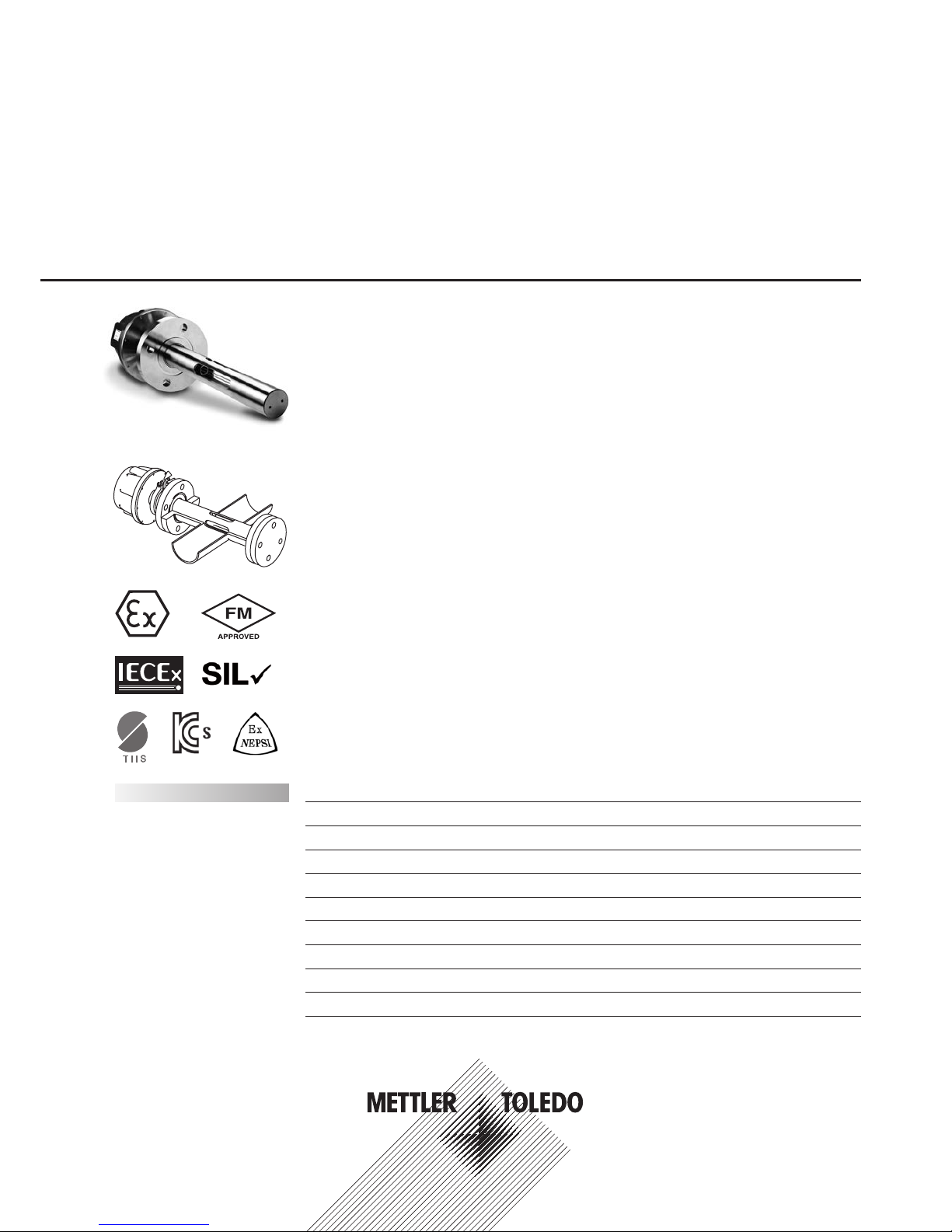
GPro 500 TDL Series
Compact Spectrometer
with Versatile Process Adaptions
Technical Data
Short description
The GPro
®
500 TDL Series is designed for tough and challenging gas measurement applications. The
series is highly suited to demanding process applications where accuracy and fast response is crucial
despite a varying background gas composition and a high dust load. The range of process adaptions
provides the ultimate in convenient process connection exibility, including for the rst time the ability to
operate without the requirement for process purge on low particulate applications using the optional non-
purge probe design. The GPro Series can be easily calibrated without interrupting the process, providing a
reliable, low maintenance and exible in situ gas measurement solution.
Outstanding features
– Interference-free in situ or extractive measurement technology
– Easy calibration without interrupting the process
– 12 month recommended verication interval
– Highly exible process adaptions
– Different styles and insertion lengths to suit applications with all types of geometry,
incl. DN50 pipes with the wafer cell
– Large selection of materials for the wetted parts
– Easy installation with either one ange, or for short pathlengths a two ange conguration,
with in-line “wafer“ cell, or with extractive cell
– No pre-alignment of anges required
– Process purge-free option for clean/dry gases (application dependent)
– Approval for hazardous areas ATEX zone 1, IECEx and FM Class 1 Div 1
– Optional SIL2 compliant direct current outputs for installation without M400
Overvi ew / General op eration 2
Inuences on the measurement / Typical applications 3
Installation examples (drawings and tables) 4
System overview 19
Measurement specications 21
Technical specications 25
Signal cable connections 27
Wiring diagrams (ATEX and US version) 28
Gas analyzer GPro 500 product key 30
Ordering information 32
Contents
GPro 500 TDL
Page 2

2
Overview / General operation GPro 500 TDL Series
Overview
Process gas analyzers are used for continuous determination of the concentration of one or more gases in
a gaseous mixture. The concentration of gases in a process is decisive for the automation and optimization
of processes to ensure product quality.
The fast measurement of gas concentrations directly in the process is the main advantage of in situ diode
laser gas analyzers. This is because in situ analytical procedures feature physical measurements directly
in the actual process. In contrast to extractive gas analysis, no sample needs to be extracted, conditioned
and routed into the analyzer via a sample line. Alternatively, the GPro 500 can be installed in a bypass line
with respect to process accessibility for manual intervention, in case of high process temperature, pressure
and / or specic geometry of the measurement location. Flexibility of the connection to the process is key to
delivering a simple to install analyzer that allows a truly representative measurement of the gas to be made
at the optimum location in the process line. A variety of insertion probes or alternative in-line wafer cells
make the GPro Series the ultimate in process connection convenience. An analyzer carrying out in situ
measurements must always take into account changing process conditions and be able to automatically
compensate for them. Therefore, accurate temperature and pressure compensation is highly recommended.
Also, extreme ruggedness of the system is important since it is in direct contact with the process gas.
The GPro 500 gas analyzer offers compact, service-friendly design with simple operation and exceptional
performance data. It is extremely rugged, requires little maintenance and provides high availability.
The GPro 500 operates in a wide range of process temperatures and pressures and remains uninuenced
by varying concentrations of dust (particles) in the gas. These features, together with fast measurements,
mean that diode laser gas analysis with the GPro 500 provides the ideal alternative to the drawbacks of
established extractive gas measurement methods.
General operation
A diode laser emits a beam of near-infrared light, which passes through the process gas and is then
reected back into the detector by an optical device that is situated and the end of the probe. The wavelength of the laser diode output is tuned to a gas specic absorption line. The laser continuously scans the
absorption lines with a very high spectral resolution. For analysis, absorption, strength and line shape of
the return signal is used. The inuence of cross interferences from background gases is negligible, since
the wavelength specic laser light is absorbed very selectively by only one specic molecule. The minimum
detectable limit, the accuracy and the resolution is dependent on the probe length (optical path length), the
process temperature and pressure.
GPro is a registered trademark of the METTLER TOLEDO Group in Switzerland, India, USA, China, European
Union, Japan, South Korea and Russia.
ISM is a registered trademark of the METTLER TOLEDO Group in Switzerland, Brazil, USA, China, European
Union, South Korea, Russia and Singapore.
Kalrez is a registered trademark of DuPont Performance Elastomers LLC.
All other trademarks are the property of their respective holders.
Page 3

3
Inuences on the measurement / Typical applications GPro 500 TDL Series
Inuences on the measurement
Dust load
As long as the laser beam is able to generate a signal for the detector, the dust load of the process gases
does not inuence the analytical result. By amplifying the signal automatically, measurements can be
carried out without any negative impact. The inuence from high dust load is complex and is dependent on
the optical path length (probe length), particle size and particle size distribution. At longer path lengths the
optical attenuation increases rapidly. Smaller particles also have a signicant impact on the optical attenuation: the smaller the particles are, the more difcult the measurement will be. For high dust load applications, please consult your local METTLER TOLEDO representative.
Temperature
The temperature inuence on an absorption line must be compensated for. An external temperature sensor
can be connected to the GPro 500. The signal is then used to correct the measurement results. Without
temperature compensation the measurement error caused by process gas temperature changes affects the
measurement substantially. Therefore, in most cases an external temperature signal is recommended.
Pressure
The process gas pressure affects the line shape of a molecular absorption line and inuences the measurement results. An external pressure sensor can be connected to the GPro 500. When the correct process gas
pressure is supplied, the GPro 500 uses a special algorithm to adapt the line shape and effectively compensate for the pressure inuence as well as the density effect. Without compensation the measurement
error caused by process gas pressure changes is substantial. Therefore, in most cases an external pressure
signal is recommended.
Cross interference
Since the GPro 500 derives its signal from one or more fully-resolved molecular absorption lines, cross
interference from other gases is eliminated. The GPro 500 is therefore able to measure the desired gas
component very selectively.
Note:
Always take great care when choosing the measurement location. Positions where there are fewer particles,
the temperature is lower or there is a more suitable process pressure, are recommended. The more optimized the measurement location is, the better the overall performance of the system will be. For advice on
the optimal measurement location, please contact your local METTLER TOLEDO representative.
Solar radiation and process radiated heat.
Exposure of the head of the GPro 500 to very high temperatures, for example, solar radiation and / or excessive localized heat sources (such as radiated heat from process walls or adjacent equipment) can cause
internal overheating of the device. See manual for further information.
Typical applications
Industry Safety Control Process Control Inertization
Chemical • • •
Petrochemical • • •
Rening • • •
Power – •
Hazardous waste – •
Tank farms / Vapor recovery • – •
Page 4
4
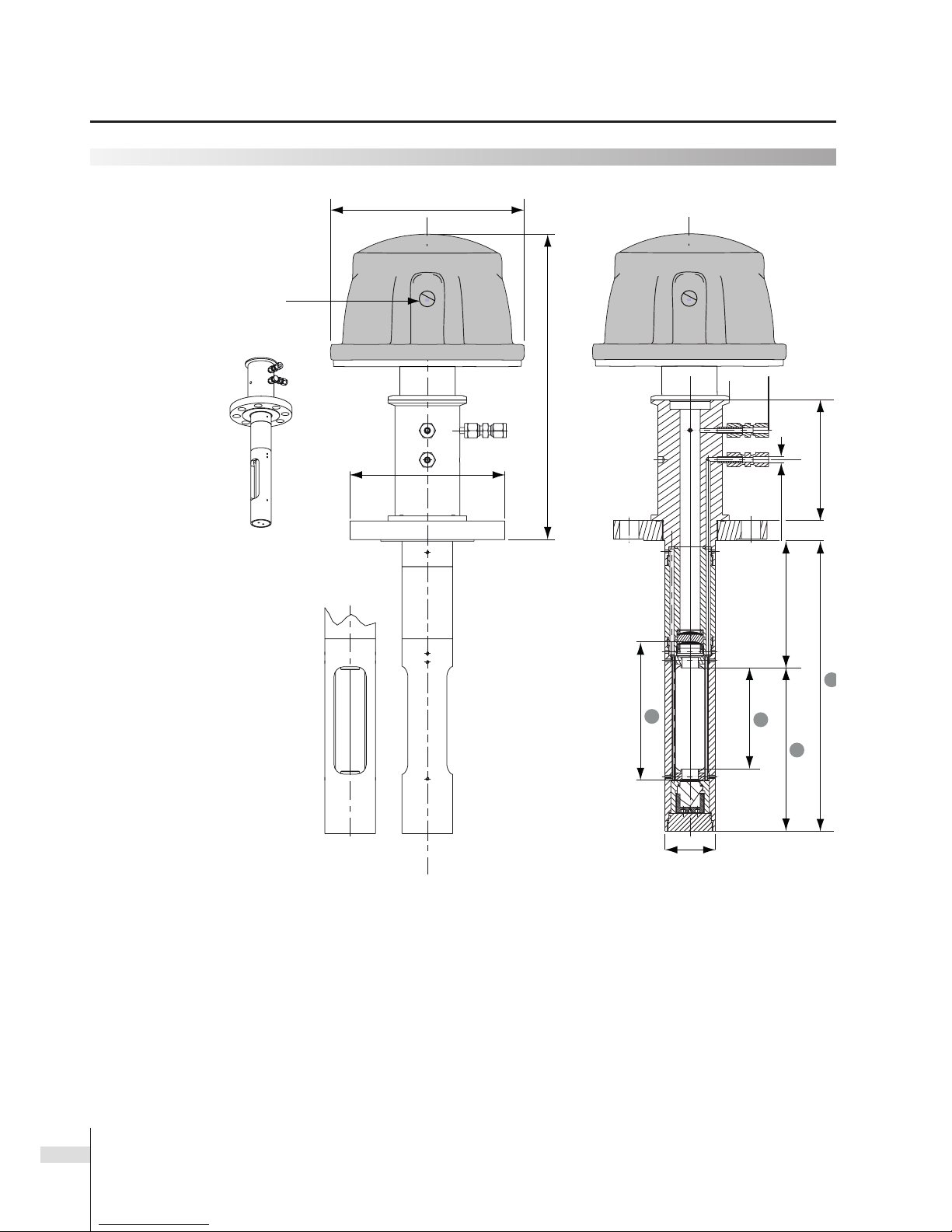
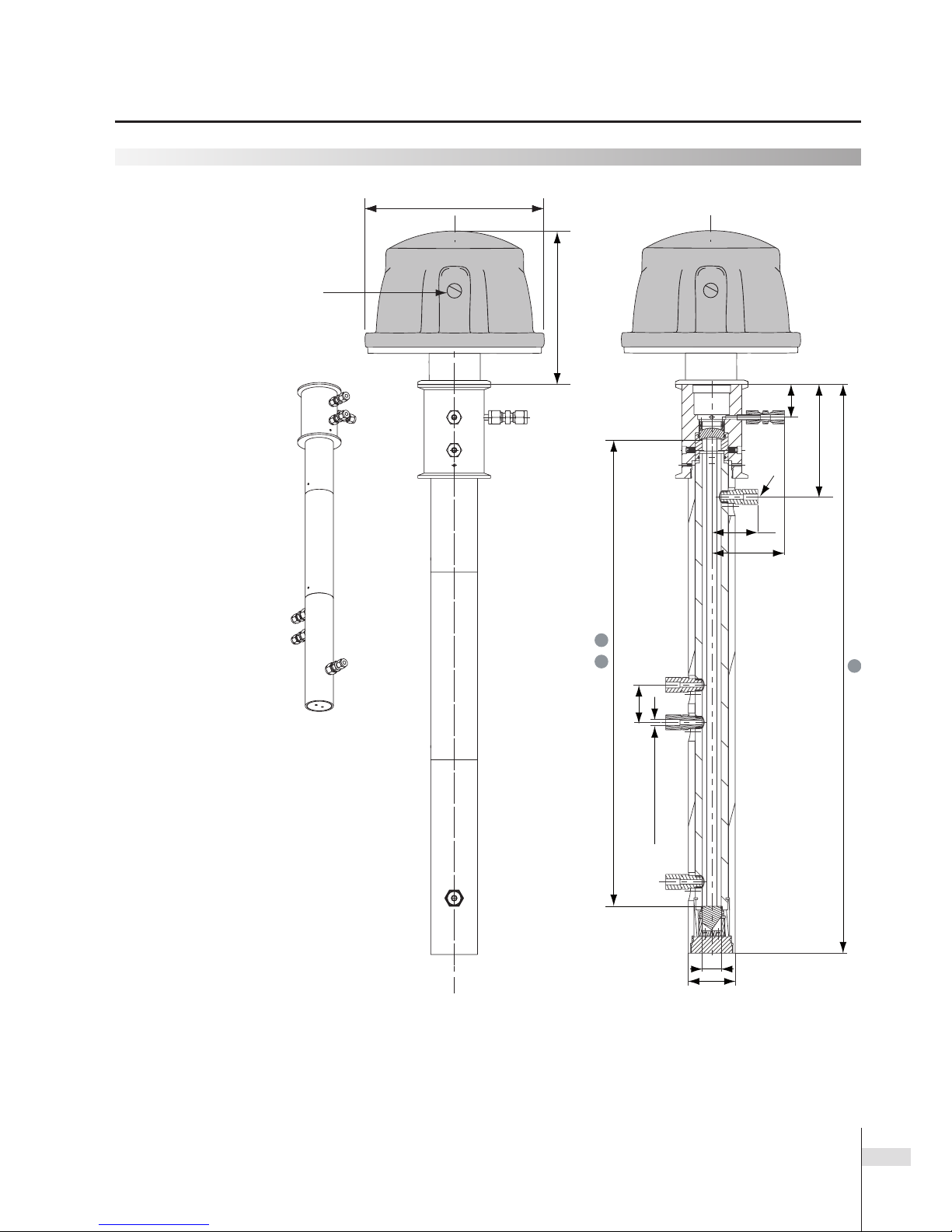
Installation examples
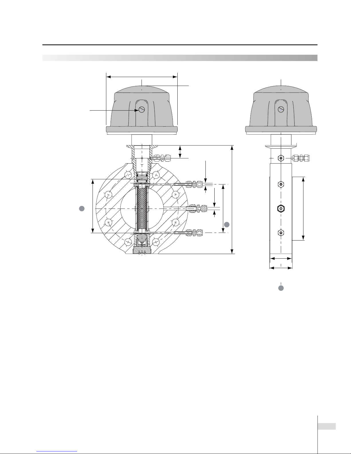
Dimensions of the
standard purged
probe (SP)
Denition of the dimensions:
➊
Nominal path length, the default length when GPro 500 is delivered.
It corresponds to the effective path length without purging.
➋
Probe length, the physical length of the probe.
➌
Insertion length, the part of the probe that has to protrude into the pipe for effective purging.
➍
Effective path length, when conguring the GPro 500 with the M400, the double value of the effec-
tive path length must be keyed in (23 effective path length).
1
3
D = ¼"
or 6 mm
4
2
119 mm (4.68")
115 mm (4.52")
50 mm (± 0,3 mm)
(1.97" [± 0.01"])
f
290 mm (11.42")
175,5 mm (6.91")
½" NPT
Installation examples (drawings) GPro 500 TDL Series
Page 5
5
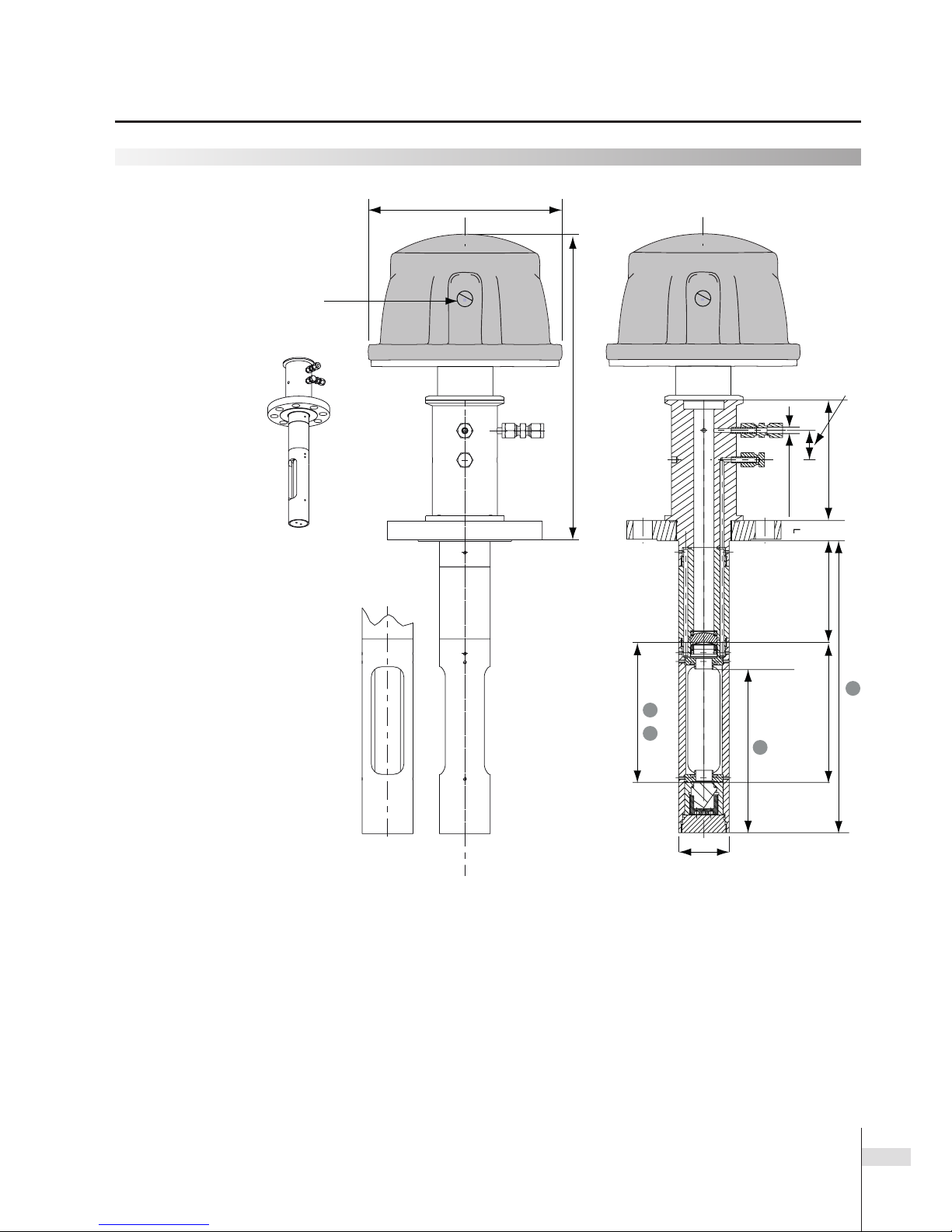
Installation examples (drawings) GPro 500 TDL Series
Installation examples
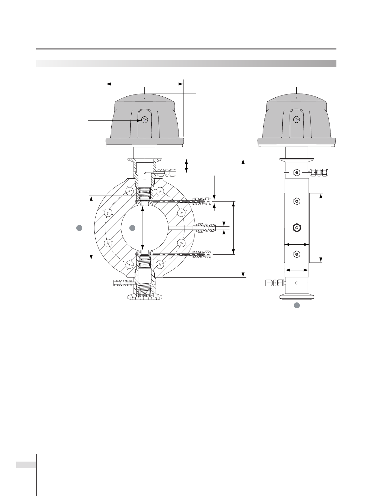
Dimensions of the
non-purged probe (NP)
with optional lter
Denition of the dimensions:
➊
Nominal path length, the default length when GPro 500 is delivered.
It corresponds to the effective path length without purging.
➋
Probe length, the physical length of the probe.
➌
Insertion length, the part of the probe that has to protrude into the pipe for effective purging.
➍
Effective path length, when conguring the GPro 500 with the M400, the double value of the effec-
tive path length must be keyed in (23 effective path length).
Note:
•
When using the PTFE lter, the maximum process gas temperature is 150 °C (302 °F).
•
Metal lters available: 3 µm, 40 µm, 100 µm, 200 µm.
50 mm (± 0,3 mm)
(1.97" [± 0.01"])
3
119 mm (4.68")
D = 6 mm or ¼"
1 4
2
138 mm (5.43")
120 mm (4.72")
29 mm (1.14")
175,5 mm (6.91")
½" NPT
290 mm (11.42")
Page 6
6
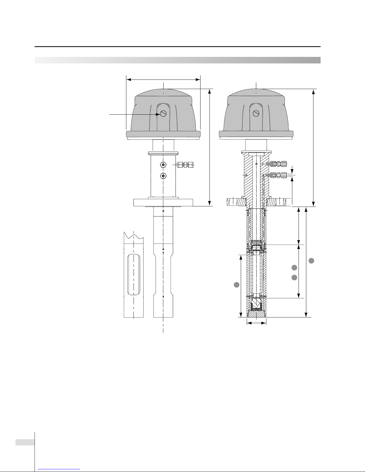
Installation examples (drawings) GPro 500 TDL Series
Installation examples
Dimensions of the non-purged
probe (B) with blow-back lter
Denition of the dimensions:
➊
Nominal path length, the default length when GPro 500 is delivered.
It corresponds to the effective path length without purging.
➋
Probe length, the physical length of the probe.
➌
Insertion length, the part of the probe that has to protrude into the pipe for effective purging.
➍
Effective path length, when conguring the GPro 500 with the M400, the double value of the effec-
tive path length must be keyed in (23 effective path length).
Note:
•
When using the PTFE lter, the maximum process gas temperature is 302 °F (150 °C).
•
Metal lters available: 3 µm, 40 µm, 100 µm, 200 µm.
50 mm (± 0,3 mm)
(1.97" [± 0.01"])
3
1
2
4
120 mm (4.72")
300 mm (11.81")
D = 6 mm or ¼"
f
290 mm (11.42")
175,5 mm (6.91")
½" NPT
Page 7
7
Installation examples (drawings) GPro 500 TDL Series
Installation examples
Dimensions of
the wafer (W)
with optional
lter
Denition of the dimensions:
➊
Nominal path length, the default length when GPro 500 is delivered.
It corresponds to the effective path length without purging.
➌
Insertion length, wafer thickness (distance between pipe anges).
➍
Effective path length, when conguring the GPro 500 with the M400, the double value of the effec-
tive path length must be keyed in (23 effective path length).
Note:
•
Filters only available on DN100/4" wafers.
•
When using the PTFE lter, the maximum process gas temperature is 302 °F (150 °C).
•
Metal lters available: 3 µm, 40 µm, 100 µm, 200 µm.
D1 = ¼"
or 6 mm
269 mm (10.59")
134.5 mm (5.29")
32 mm
(1.26")
D2 = ¼"
or 6 mm BT
120 mm (4.72")
1
4
157.20 mm (6.20")
54 mm
(2.13")
57 mm
(2.24")
3
175,5 mm (6.91")
½" NPT
Page 8
8
Installation examples (drawings) GPro 500 TDL Series
Installation examples
Dimensions of
the Wafer (W)
Dual Window
Denition of the dimensions:
➊
Nominal path length, the default length when GPro 500 is delivered.
It corresponds to the effective path length without purging.
➌
Insertion length, wafer thickness (distance between pipe anges).
➍
Effective path length, when conguring the GPro 500 with the M400, the double value of the effec-
tive path length must be keyed in (23 effective path length).
157.2 mm (6.20")
54 mm
(2.13")
57 mm
(2.24")
3
D1 = ¼"
or 6 mm
320 mm (12.60")
134.5 mm (5.29")
32 mm
(1.26")
D2 = ¼"
or 6 mm BT
120 mm (4.72")
1
4
100 mm (3.94")
175,5 mm (6.91")
½" NPT
Page 9
9
Installation examples (drawings) GPro 500 TDL Series
Installation examples
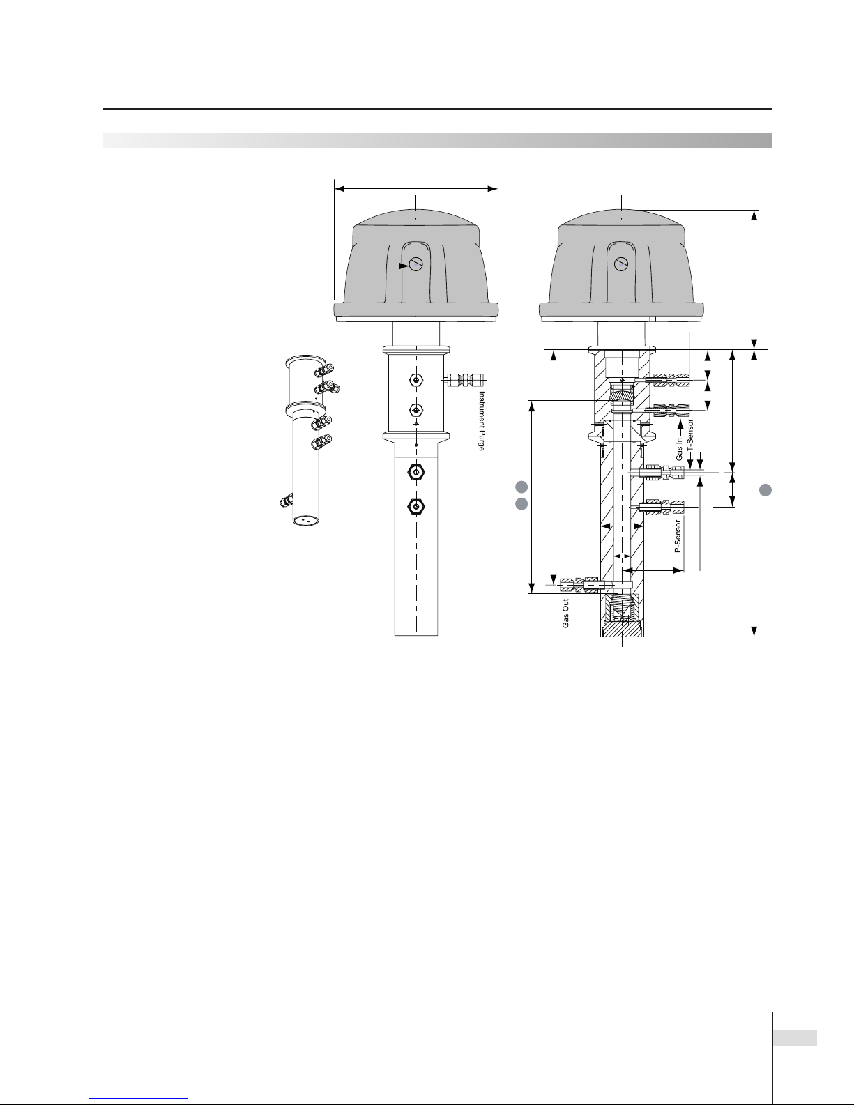
Dimensions of the
extractive cell (E)
Denition of the dimensions:
➊
Nominal path length, the default length when GPro 500 is delivered.
It corresponds to the effective path length without purging.
➋
Probe length, the physical length of the probe.
➍
Effective path length, when conguring the GPro 500 with the M400, the double value of the effec-
tive path length must be keyed in (23 effective path length).
272 mm (10.70")
150 mm (5.90")
D = 6 mm or ¼" (BT)
35 mm
(1.37")
35 mm
(1.37")
50 mm
(1.96")
20 mm
(0.78")
71 mm
(2.79")
142 mm (5.59")
40 mm
(1.57")
2
41
175,5 mm (6.91")
½" NPT
Page 10
10
Installation examples (drawings) GPro 500 TDL Series
Installation examples
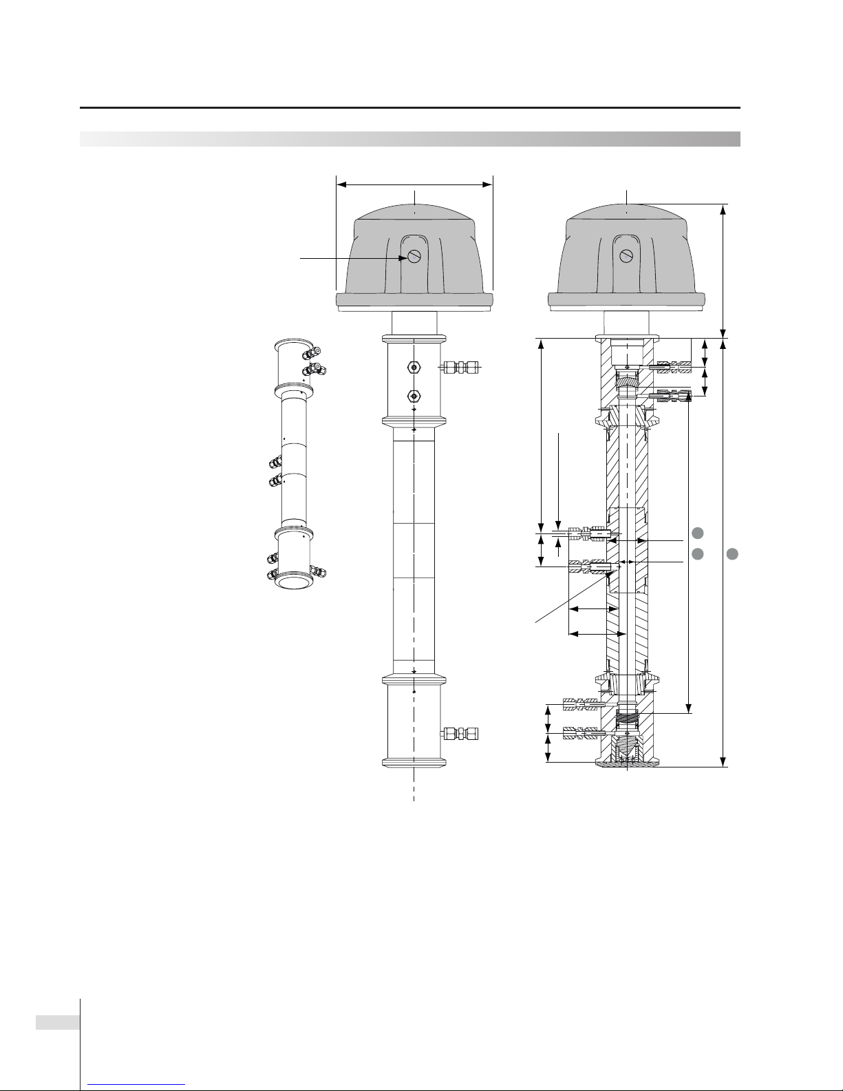
Dimensions of the extractive
cell dual window (DW)
Denition of the dimensions:
➊
Nominal path length, the default length when GPro 500 is delivered.
It corresponds to the effective path length without purging.
➋
Probe length, the physical length of the probe.
➍
Effective path length, when conguring the GPro 500 with the M400, the double value of the effec-
tive path length must be keyed in (23 effective path length).
35 mm
(1.37")
35 mm
(1.37")
2
1 4
35 mm
(1.37")
35 mm
(1.37")
50 mm
(1.97")
20 mm
(0.78")
238 mm (9.37")
40 mm
(1.57")
D = 6 mm or ¼" (BT)
61 mm
(2.40")
71 mm
(2.79")
150 mm (5.90")
Bore-through
P-Sensor
T-SensorGas IN
Gas OUT
175,5 mm (6.91")
½" NPT
Page 11
11
Installation examples
Dimensions of the
extractive cell (E) PFA
Denition of the dimensions:
➊
Nominal path length, the default length when GPro 500 is delivered.
It corresponds to the effective path length without purging.
➋
Probe length, the physical length of the probe.
➍
Effective path length, when conguring the GPro 500 with the M400, the double value of the effec-
tive path length must be keyed in (23 effective path length).
2
35 mm
(1.38")
120 mm (4.72")
49 mm
(1.92")
78 mm
(3.07")
41
40 mm
(1.57")
PFA, D = 6 mm or
¼" (BT)
50 mm (1.96")
20 mm (0.78")
Gas IN
Gas
OUT
P-SensorT-Sensor
150 mm (5.90")
175,5 mm (6.91")
½" NPT
Installation examples (drawings) GPro 500 TDL Series
Page 12

12
Installation examples
Dimensions of the
extractive (E) white cell
Denition of the dimensions:
➊
Nominal path length, the default length when GPro 500 is delivered.
It corresponds to the effective path length without purging.
➋
Probe length, the physical length of the probe.
➍
Effective path length, when conguring the GPro 500 with the M400, the double value of the effec-
tive path length must be keyed in (23 effective path length).
Note:
•
For oxygen measurement only.
1
4
100 mm
(± 0,3 mm)
(3.93")
(± 0.01")
Gas
Outlet
Gas
Inlet
2
175,5 mm (6.91")
½" NPT
G ¼" G ¼"
Installation examples (drawings) GPro 500 TDL Series
Page 13

13
Installation examples (drawings) GPro 500 TDL Series
Installation examples
Dimensions of the
cross pipe
Denition of the dimensions:
➊
Nominal path length, the default length when GPro 500 is delivered (conguration dependent).
It corresponds to the effective path length without purging.
➍
Effective path length, when conguring the GPro 500 with the M400, the double value of the effec-
tive path length must be keyed in (23 effective path length).
D = 6 mm
or ¼"
1
4
300 mm (11.81")
136 mm (5.35")
129 mm (5.07")
44 mm
(1.73")
25 mm
(0.98")
Process Purge
45 mm
(1.77")
31 mm
(1.22")
82 mm (3.22")
175,5 mm (6.91")
½" NPT
Page 14

14
Installation examples (tables) GPro 500 TDL Series
Installation examples
Probes, wafer and cell dimensions
Process interface OPL Dimension
➊
Dimension ➋ Dimension ➌ Dimension
➍
Standard purged (SP) 200 mm 138 mm 288 mm 161.5 mm 100 mm
(7.9") (5.4") (11.3") (6.4") (3.9")
Standard purged (SP) 400 mm 238 mm 388 mm 261.5 mm 200 mm
(15.7") (9.4") (15.3") (10.3") (7.9")
Standard purged (SP) 800 mm 438 mm 588 mm 461.5 mm 400 mm
(31.5") (17.2") (23.1") (18.2") (15.7")
Non-purged probe (NP) 200 mm 138 mm 288 mm 161.5 mm 138 mm
(7.9") (5.4") (11.3") (6.4") (5.4")
Non-purged probe (NP) 400 mm 238 mm 388 mm 261.5 mm 238 mm
(15.7") (9.4") (15.3") (10.3") (9.4")
Non-purged probe (NP) 800 mm 438 mm 588 mm 461.5 mm 438 mm
(31.5") (17.2") (23.1") (18.2") (17.2")
Non-purged probe (NP) with lter 200 mm 138 mm 288 mm 161.5 mm 138 mm
(7.9") (5.4") (11.3") (6.4") (5.4")
Non-purged probe (NP) with lter 400 mm 238 mm 388 mm 261.5 mm 238 mm
(15.7") (9.4") (15.3") (10.3") (9.4")
Non-purged probe (NP) with lter 800 mm 438 mm 588 mm 461.5 mm 438 mm
(31.5") (17.2") (23.1") (18.2") (17.2")
Non-purged lter probe with blow-back (NB) 200 mm 138 mm 288 mm 161.5 mm 138 mm
(7.9") (5.4") (11.3") (6.4") (5.4")
Non-purged lter probe with blow-back (NB) 400 mm 238 mm 388 mm 261.5 mm 238 mm
(15.7") (9.4") (15.3") (10.3") (9.4")
Non-purged lter probe with blow-back (NB) 800 mm 438 mm 588 mm 461.5 mm 438 mm
(31.5") (17.2") (23.1") (18.2") (17.2")
DN 50 wafer (W) 110 mm 79 mm n.a. 54 mm 55 mm
(4.33") (3.11") (2.13") (2.17")
DN 80 wafer (W) 164 mm 121 mm n.a. 54 mm 82 mm
(6.46") (4.76") (2.13") (3.29")
DN 100 wafer (W) 214 mm 157 mm n.a. 54 mm 107 mm
(8.43") (6.18") (2.13") (4.21")
ANSI 2" wafer (W) 104 mm 77 mm n.a. 54 mm 52 mm
(4.09") (3.03") (2.13") (2.05")
ANSI 3" wafer (W) 154 mm 99 mm n.a. 54 mm 77 mm
(6.06") (3.90") (2.13") (3.03")
ANSI 4" wafer (W) 214 mm 157 mm n.a. 54 mm 107 mm
(8.43") (6.18") (2.13") (4.21")
Cross pipe 2000 – 6000 mm 2000 – 6000 mm n.a. n.a.
➊
– 300 mm
(78.74" – 236.22") (78.74" – 236.22") (
➊
– 118 .1 " )
continued on next page
Page 15

15
Installation examples (tables) GPro 500 TDL Series
Probes, wafer and cell dimensions, continued
Process interface OPL Dimension
➊
Dimension ➋ Dimension ➌ Dimension
➍
Extractive cell (E) 200 mm 125 mm 232mm N.A 125 mm
(7.9") (4.9") (9.1") N.A (4.9")
Extractive cell (E) 400 mm 225 mm 332 mm N.A 225 mm
(15.7") (8.9") (13.1") N.A (8.9")
Extractive cell (E) 800 mm 425 mm 532 mm N.A 425 mm
(31.5") (16.7") (20.9") N.A (16.7")
Extractive cell (E) 1000 mm 525 mm 632 mm N.A 525 mm
(39.4") (20.7") (24.9") N.A (20.7")
Extractive cell Dual Window(E) 400 mm 200 mm 321 mm N.A 200 mm
(15.7") (7.9") (12.6") N.A (7.9")
Extractive cell Dual Window(E) 800 mm 400 mm 521 mm N.A 400 mm
(31.5") (15.7") (20.5") N.A (15.7")
Extractive cell Dual Window(E) 1000 mm 500 mm 621 mm N.A 500 mm
(39.4") (19.7") (24.4") N.A (19.7")
Extractive cell (E) PFA 1000 mm 500 mm 606.5 mm N.A 500 mm
(39.4") (19.7") (23.9") N.A (19.7")
Extractive white cell (E) 10000 mm 250 mm 432 mm N.A 250 mm
(393.7.0") (9.8") (17.0") N.A (9.8")
* Note: Dimension
➋
in above table applies for standard 100 mm stand-off. For total probe length dimensions for other stand-off lengths,
please refer to product congurator.
Page 16

16
Installation examples (tables) GPro 500 TDL Series
Sampling and conditioning system (SCS) Design requirements
• Sampled gases must be dry and dust-free. Flow can be user-dened.
• Heat tracing of the cell up to the maximum design temperature is allowed, but maximum spectrameter ambient temperature is 55 °C
(131 °F ).
Internal volume Maximum design pressure Maximum design temperature
Extractive cell (E) 10 bar a 250 °C / 482 °F
Extractive cell (E) 10 bar a 250 °C / 482 °F
Extractive cell (E) 10 bar a 250 °C / 482 °F
Extractive cell (E) 10 bar a 250 °C / 482 °F
Extractive cell Dual Window(E) 10 bar a 250 °C / 482 °F
Extractive cell Dual Window(E) 10 bar a 250 °C / 482 °F
Extractive cell Dual Window(E) 10 bar a 250 °C / 482 °F
Extractive cell (E) PFA 5 bar a 150 °C / 302 °F
Extractive white cell (E) 10 bar a 150 °C / 302 °F
Page 17

17
Installation examples (tables) GPro 500 TDL Series
Installation examples
Required anges for some typical standard probe (SP) congurations (100 mm stand-off)
➊
Nominal
➋
Probe
➌
Insertion
➍
Effective Pipe size Number of
path length length length path length * DN / SPS anges
138 mm 288 mm 161.5 mm 100 mm 100 mm 2
(5.4") (11.3") (6.4") (3.9") (3.94")
138 mm 288 mm 161.5 mm 100 mm 150 mm 2
(5.4") (11.3") (6.4") (3.9") (5.91")
138 mm 288 mm 161.5 mm 100 mm 200 mm 1
(5.4") (11.3") (6.4") (3.9") (7.87)
238 mm 388 mm 261.5 mm 200 mm 200 mm 2
(9.4") (15.3") (10.3") (7.9") (7.87")
238 mm 388 mm 261.5 mm 200 mm 250 mm 2
(9.4") (15.3") (10.3") (7.9") (9.84")
238 mm 388 mm 261.5 mm 200 mm 300 mm 1
(9.4") (15.3") (10.3") (7.9") (11.81")
438 mm 588 mm 461.5 mm 400 mm 300 mm 2
(17.2") (23.1") (18.2") (15.7") (11.81")
438 mm 588 mm 461.5 mm 400 mm 400 mm 2
(17.2") (23.1") (18.2") (15.7") (15.75")
438 mm 588 mm 461.5 mm 400 mm 500 mm 1
(17.2") (23.1") (18.2") (15.7") (19.69")
438 mm 588 mm 461.5 mm 400 mm 600 mm 1
(17.2") (23.1") (18.2") (15.7") (23.62")
* When conguring the GPro 500 with the M400, the double value of the effective path length must be
keyed in (23 effective path length).
Page 18

18
Installation examples GPro 500 TDL Series
Installation examples (SP probe)
One and two ange conguration
By-pass conguration (SP probe)
Example of typical by-pass conguration.
* Default stand-off length shown.
100 mm
(4")
(*)
100 mm
(4")
DIN 50 or ANSI 2"
DIN 65 or ANSI 2½"
min. clearance: 61,5 mm
(schedule 40)
min. clearance: 77,5 mm
(schedule 80)
(*)
One ange conguration
Default* stand-off for standard probe (SP).
Other stand-offs distances available:
200 mm (8") and 300 mm (12").
Two ange conguration
Default* stand-off for standard probe (SP).
Other stand-off distances available:
200 mm (8") and 300 mm (12").
300 mm
(11.81'')
100 mm
(4'')
100 mm
(4'')
100 mm
(4'')
*
Page 19

19
System overview
The GPro Series consists of four main components:
➊
Sensor head
The combined transmitter and receiver unit is called the sensor head. This part contains the laser, optics
and all the electronics for laser control, signal processing, line locking, detector electronics, etc. The sensor
head has an Ethernet interface for high level maintenance by the use of METTLER TOLEDO Process Analytics specic soft ware. All parts of the sensor head are non-wetted and are never in contact with the process.
If this feature has been selected when purchasing the analyzer, the GPro 500 can also provide 2 3 4 … 2 0
mA passive analog outputs directly from the sensor head (SIL2).
➋
Process adaption
The probe exists in several standard versions where both material of construction and insertion length can
be customized to particular needs. The wafer is available in a variety of sizes, to suit pipes sizes of DN50,
DN80, DN100 or ANSI 2", ANSI 3" or ANSI 4".
➌
M400 G2 type 3 transmitter
The M400 is the GPro 500 user interface. Using the M400, the user can set the necessary parameters for
operation, and control the alarm and I / O setup. The M400 will also display the measured gas concentration, the process temperature and pressure as well as the transmission (signal quality / strength). It features
class 1 Div 2 FM approval (ATEX zone 2) and four active 4 – 20 mA analog outputs.
➍
Junction box
A junction box is required between the sensor head and the M400. An existing junction box can be used,
or one can be ordered as an accessory. The 4 – 20 mA signals for temperature and pressure compensation
are connected to the sensor’s head through the junction box. The Ethernet interface can be accessed
through the junction box as well.
➌
➊
➋
➍
(optional)
System overview GPro 500 TDL Series
Page 20

20
System overview GPro 500 TDL Series
System overview
Material of construction for process adaptions
Wetted Parts 1.4404 (comparable to 316L), 1.4571, Hastelloy C22, PFA
Glass, Optics AR coated Quartz, AR coated Borosilicate, Sapphire
O-rings, Gaskets Kalrez
®
6375, Kalrez® (FDA) 6230, 6380 (Spectrum), 0090 (RGN),
Graphite, PFA-O-Seal PTFE
Probe lengths. Standard purged (SP)
290 mm / 11.42"
390 mm / 15.35"
590 mm / 23.23"
Probe lengths. Non-purge probes (NP)
290 mm / 11.42"
390 mm / 15.35"
590 mm / 23.23"
Probe lengths. Non-purged lter probe with blow-back (NB)
290 mm / 11.42"
390 mm / 15.35"
590 mm / 23.23"
Probe lengths. Non-purged probes (NP) with lter
290 mm / 11.42"
390 mm / 15.35"
590 mm / 23.23"
Wafer sizes (to t pipe diameter)
DN 50, 80 or 100; PN16/PN40
ANSI 2", 3" or 4"; 150 lbs
Other materials of construction as well as different probe lengths are available upon request.
Page 21

21
Measurement (All measurement specications with reference to standard conditions T & P with no dust or particulates)
O
2
O
2
and temperature CO (ppm)
Optical path length • Optical path length (OPL) can vary between 100 mm and 10 m depending on the selected process adaption
(see “Installation examples” on page 14).
• The OPL can be multiplied by 2 (MR2) or 4 (MR4) when using the multi-reflection cell (MR).
Measurement range and standard
conditions (ambient temperature and
pressure, 1 m path length)
0 – 100 % 1 – 100 %
0 – 150 °C (32 – +302 °F)
0 – 2 %
Lower Detection Limit (in 1 meter path
length at ambient standard conditions,
dry gas, no dust load, in N
2
back-
ground)
100 ppm-v 100 ppm-v
2 °C (35.6 °F)
1 ppm-v
Accuracy 2 % of reading or 100 ppm O
2
( whichever is greater)
2 % of reading or 100 ppm O
2
( whichever is greater)
2 % of reading or 1 ppm
( whichever is greater)
Linearity Better than 1 % Better than 1 % Better than 1 %
Resolution < 0…01 % vol O
2
(100 ppm-v) < 0…01 % vol O
2
(100 ppm-v) 1 ppm-v
Drift Negligible (< 2 % of measurement ran-
ge between maintenance intervals)
Negligible (< 2 % of measurement ran-
ge between maintenance intervals)
Negligible (< 2 % of measurement ran-
ge between maintenance intervals)
Sampling rate 1 second 1 second 1 second
Response Time (T90) O
2
in N
2
21 % > 0 % in < 2 se c O
2
in N
2
21 % > 0 % in < 2 se c CO in N
2
300 ppm-v to 0 % in < 4 sec
Warm up time Typically <1 hour Typically <1 hour Typically <1 hour
Repeatabilit y ± 0.25 % of re ading or 0.05 % O
2
(whichever is greater)
± 0.25 % of re ading or 0.05 % O
2
(whichever is greater)
± 0.25 % of reading or 5 ppm-v CO
(whichever is greater)
Process pressure range 0.3 bar – 10 bar (abs)/
4.35 psi – 145.03 psi (abs)*
0.8 bar – 5 bar (abs)/
11.63 psi – 72.52 psi (abs)
0.8 bar – 2 bar (abs)/
11.63 psi – 29.00 psi (abs)
Process temperature range 0 to + 250 °C (+ 32 to + 482 °F) Standard
0 to + 600 °C (0 to +1112 °F) with built in thermal barrier,
0 to +150 °C (+ 32 to + 302 °F) (White cell, PFA, PTFE filter)
* from Firmware 6.23 or higher
Measurement specications GPro 500 TDL Series
Page 22

22
Measurement (All measurement specications with reference to standard conditions T & P with no dust or particulates)
CO ( %) H
2
O CO
2
( %)
Optical path length • Optical path length (OPL) can vary between 100 mm and 10 m depending on the selected process adaption
(see “Installation examples” on page 14).
• The OPL can be multiplied by 2 (MR2) or 4 (MR4) when using the multi-reflection cell (MR).
Measurement range and standard
conditions (ambient temperature and
pressure, 1m path length)
0 – 100 % 0 – 20 % 0 – 100 %
Lower Detection Limit (in 1meter path
length at ambient standard conditions,
dry gas, no dust load, in N
2
back-
ground)
1500 ppm-v 5 ppm-v 1000 ppm-v
Accuracy 2 % of reading or 1500 ppm,
(whichever is greater)
2 % of reading or 10 ppm,
(whichever is greater)
2 % of reading or 1000 ppm,
(whichever is greater)
Linearity Better than 1 % Better than 1 % Better than 1 %
Resolution 1500 ppm-v 5 ppm-v 1000 ppm-v
Drift Negligible (< 2 % of measurement ran-
ge between maintenance intervals)
Negligible (< 2 % of measurement ran-
ge between maintenance intervals)
Negligible (< 2 % of measurement ran-
ge between maintenance intervals)
Sampling rate 1 second 1 second 1 second
Response Time (T90) CO in N
2
1% to 0% in < 4 sec H
2
O in N
2
1 % to O % in < 4 sec CO
2
in N
2
1 % to O % in < 4 sec
Warm up time Typically <1 hour Typically <1 hour Typically <1 hour
Repeatabilit y ± 0.25 % of reading or 0.75 %-v CO
(whichever is greater)
± 0.25 % of reading or 50 ppm-v H
2
O
(whichever is greater)
± 0.25 % of re ading or
5000 ppm-v CO
2
(whichever is greater)
Process pressure range 0.8 bar – 1.5 bar (abs)/
11.63 psi – 21.75 psi (abs)
0.8 bar – 2 bar (abs)/
11.63 psi – 29.00 psi (abs)
0.8 bar – 2 bar (abs)/
11.63 psi – 29.00 psi (abs)
Process temperature range 0 to + 250 °C (+ 32 to + 482 °F) Standard
0 to + 600 °C (0 to +1112 °F) with built in thermal barrier,
0 to +150 °C (+ 32 to + 302 °F) (White cell, PFA, PTFE filter)
Measurement specications GPro 500 TDL Series
Page 23

23
Technical specications GPro 500 TDL Series
Measurement (All measurement specications with reference to standard conditions T & P with no dust or particulates)
CO
2
%/ CO % HCl (ppm) H
2
S (%)
Optical path length • Optical path length (OPL) can vary between 100 mm and 10 m depending on the selected process adaption
(see “Installation examples” on page 14).
• The OPL can be multiplied by 2 (MR2) or 4 (MR4) when using the multi-reflection cell (MR).
Measurement range and standard
conditions (ambient temperature and
pressure, 1m path length)
0 – 100 %
(CO
2
and CO)
0 – 3 % 0 –50 %
Lower Detection Limit (in 1meter path
length at ambient standard conditions,
dry gas, no dust load, in N
2
back-
ground)
1000 ppm-v (CO
2
)
1500 ppm-v (CO)
0.6 ppm-v 20 ppm-v
Accuracy 2 % of reading or 1000 ppm
(whichever is greater)
2 % of reading or 0.6 ppm
(whichever is greater)
2 % of reading or 20 ppm
(whichever is greater)
Linearity Better than 1 % Better than 1 % Better than 1 %
Resolution 1000 ppm-v 0.6 ppm-v 20 ppm-v
Drift Negligible (< 2 % of measure ment
range between maintenance intervals)
Negligible (< 2 % of measure ment
range between maintenance intervals)
Negligible (< 2 % of measure ment
range between maintenance intervals)
Sampling rate 1 second 1 second 1 second
Response Time (T90) CO
2
in N
2
1 % to O % in < 4 sec HCl in N
2
1 % to O % in < 4 sec H
2
S in N
2
1 % to O % in < 4 sec
Warm up time Typically <1 hour Typically <1 hour Typically <1 hour
Repeatabilit y ± 0.25 % of re ading or
5000 ppm-v CO
2
or CO
(whichever is greater)
± 0.25 % of reading or 3 ppm-v HCl
(whichever is greater)
± 0.25 % of reading or 100 ppm-v H
2
S
(whichever is greater)
Process pressure range 0.8 bar – 2 bar (abs)/
11.63 psi – 29.00 psi (abs)
0.8 bar – 3 bar (abs)/
11.6 psi – 43.5 psi (abs)
0.8 bar – 2 bar (abs)/
11.6 psi – 29 psi (abs)
Process temperature range 0 to + 250 °C (+ 32 to + 482 °F) Standard
0 to + 600 °C (0 to +1112 °F) with additional thermal barrier,
0 to +150 °C (+ 32 to + 302 °F) (White cell, PFA, PTFE filter)
Page 24

24
Measurement (All measurement specications with reference to standard conditions T & P with no dust or particulates)
CH
4
ppm NH
3
ppm
Optical path length • Optical path length (OPL) can vary between 100 mm and 10 m depending on the selected process adaption
(see “Installation examples” on page 14).
• The OPL can be multiplied by 2 (MR2) or 4 (MR4) when using the multi-reflection cell (MR).
Measurement range and standard
conditions (ambient temperature and
pressure, 1m path length)
0 – 1 % 0 – 1 %
Lower Detection Limit (in 1meter path
length at ambient standard conditions,
dry gas, no dust load, in N
2
back-
ground)
1 ppm-v 1 ppm-v
Accuracy 2 % or 1 ppm
(whichever is greater)
2 % or 1 ppm
(whichever is greater)
Linearity Better than 1 % Better than 1 %
Resolution 1 ppm 1 ppm
Drift Negligible (< 2 % of measure ment
range between maintenance intervals)
Negligible (< 2 % of measure ment
range between maintenance intervals)
Sampling rate 1 second 1 second
Response Time (T90) CH
4
in N
2
1% to 0% in < 4 sec NH
3
in N
2
1% to 0% in < 4 sec
Warm up time Typically <1 hour Typically <1 hour
Repeatabilit y ± 0.25 % of re ading or
5 ppm-v CH
4
,
(whichever is greater)
± 0.25 % of re ading or
5 ppm-v NH
3
,
(whichever is greater)
Process pressure range 0.8 bar – 3 bar (abs)/
11.63 psi – 43.5 psi (abs)
0.8 bar – 3 bar (abs)/
11.63 psi – 43.5 psi (abs)
Process temperature range 0 to + 250 °C (+ 32 to + 482 °F) Standard
0 to + 600 °C (0 to +1112 °F) with additional thermal barrier,
0 to +150 °C (+ 32 to + 302 °F) (White cell, PFA, PTFE filter)
Measurement specications GPro 500 TDL Series
Page 25

25
Technical specications GPro 500 TDL Series
Technical specications
Electrical inputs & outputs
Communication interface RS 485 (to transmit ter) or direct current outputs (optional)
Service interface Ethernet (to PC) as direct service interface for FW updates (not using
the M400 transmitter), for off-line diagnostics and conguration
database up / download
Memory slot interface SD card reader / writer for data retrieval (measurement & diagnos-
tics), FW update and remote diagnostics (conguration le up / download) (to be accessed using Ethernet port). Space for data storage: 4
GB.
Analog outputs (on M400) 4 3 4 – 20 mA (22 mA): process temperature, pressure, % conc,
% transmission
Number of direct analog outputs 2 (optional)
Current outputs Passive 4…20 mA outputs, galvanically isolated,
alarms to 3.6 mA or 22 mA conform to NAMUR NE43 guidelines
Measurement error Non-linearity < ± 0.002 mA over the 1 to 20 mA range
through analog outputs Offset error < ± 0.004 mA (zero scale)
Gain error < ± 0.04 mA (full scale)
Analog output conguration Linear
Load Max 500 Ohms
Hold mode input Yes, via Ethernet (using the MT-TDL suite)
Analog inputs 2 3 4 – 20 mA (passive) for pressure and temperature
(optional: xed values)
Display On M400, see M400 technical datasheet
Relays 4 relays (on M400)
Power supply 24 VDC, ± 10% , 5 – 60 W
Fuse 1 A slow blow type FC
Calibration
Calibration (factory) Full calibration
Calibration (user) One-point and process calibration
Operating conditions
Ambient temperature range – 20 … + 55 °C (– 4 … +131 °F) during operation;
– 40 … +70 °C (– 40 … +158 °F) during transport and storage
(< 95 % non-condensing humidity)
Maximum design
(non- operating) Pressure Design: 25 bar (abs) / 362.6 psi (abs);
extractive cells: 15 bar (PFA version: 6 bar)
Probes with DN 100 anges: 10 bar
Max. dust load @ nom. EPL Application dependent
Temperature & pressure Using analog 4 … 20 mA input signals or manually set values in
compensation M400 (menu congure / measurement).
Automatic plausibility check of analog inputs
Page 26

26
Purging
Process side purging For standard purged (SP) and wafer cells, a process side purge is
(standard probes [SP]) normally required.
and wafer cells For oxygen applications, nitrogen with a purity > 99.7 % (minimum
recommended) at a ow rate of between 0.5 and 10 L / min (applica-tion dependent) is required. For other gas applications, instru-
ment grade air can be used instead of nitrogen. All purge gases
should be clean / dry and conform to standard ISO 8573.1. class 2 3,
for instrument air quality.
Instrument side purging Yes, ow < 0.5 L / min (all process adaptions)
Corner cube purging Yes, via process side purging
ISM
ISM
®
diagnostics parameters % Transmission (available as a 4 … 20 mA analog output)
Window fouling (➝ TTM: Time to Maintenance)
Laser lifetime (➝ DLI: Dynamic Lifetime Indicator)
Alarms
Alarm triggers Too low transmission (min. transmission value to be set in
M400 menu Cong / ISM setup)
All alarms (incl SW / HW errors etc) listed into Chapter 8.5.1 of man-
ual M400
Mechanical specications
Insertion length see installation examples
Weight 12 – 14 kg / 26 – 30 lbs, depending on conguration
Insulation / rating IP 65 / NEMA Type 4X
Data logger
Function Logging of all sensor data on SD card
Interval Freely selectable using the METTLER TOLEDO TDL software
(on documentation CD)
Format SPC
Certicates
Quality certicate (nal inspection), Material certicate 3.1,
EX II 1/2G – Ex op is / [op is T6 Ga] d IIC T6 Ga / Gb,
EX II 1/2D – Ex op is / [op is T86°C Da] tb IIIC T80°C Da / Db,
IECEx IBE 15.0013 X
Cl I, Div 1, Grp A, B, C, D, T6
Cl II, III, Div 1, Grp E, F, G, T6
FM, CE, PED, IP 65, NEMA 4X
Technical specications GPro 500 TDL Series
Page 27

27
Signal cable connections
Connections in the junction box
➊
Connections to the GPro 500 – cable numbers below
➋
Power from an external source or optionally from the M400
➌
RS 485 from the M400
➍
4 … 20 mA from temperature sensor
➎
4 … 20 mA from pressure sensor
➏
SIL2 direct analog outputs (optional)
➐
Ethernet
Signal Description Cable no. Color
Power + 24 V Power 24 V, 5 W 1 Red
GND (Power) 2 Blue
RS 485 A Interface M400 (RS 485) 3 Green
RS 485 B 4 Yellow
RS 485 GND 5 Brown
4 … 20 mA pos Current input temperature 6 Purple
4 … 20 mA neg 7 Black
4 … 20 mA pos Current input pressure 8 Pink
4 … 20 mA neg 9 Grey
+ 24 V Passive analog outputs 10 Red / blue
Out 1 11 Grey / pink
Out 2 12 White
TX+ Ethernet 13 White / yellow
TX– 14 Yellow / brown
RX+ 15 White / green
RX– 16 Brown / green
1
2 3 6 74 5
1 2 3 4 5 6 7 8 9 10 11 12 13 14 15 16
Signal cable connections GPro 500 TDL Series
Page 28

28
Active analog inputs (ATEX and US version)
Wiring diagram with active analog inputs (ATEX and US version).
Wiring diagrams (ATEX and US version) GPro 500 TDL Series
Page 29

29
Loop-powered analog inputs (ATEX and US version)
Wiring diagram with loop-powered analog inputs (ATEX and US version).
Wiring diagrams (ATEX and US version) GPro 500 TDL Series
Page 30

30
Gas analyzer GPro 500 product key GPro 500 TDL Series
Gas analyzer GPro 500 product key
Gas Analyzer
GPro 500
ATA0PBKS020PD1XS__/AX
30 027 126 GPro 500
YYYYYYYYYYYYYYYYYY/YY
* Other configurations upon request
|||||||||||||||||||
|
Hazardous area approvals
|||||||||||||||||||
|
ATEX/IECEx Ex d
A
T
|||||||||||||||||
|
FM Class 1 Div 1
U
S
|||||||||||||||||
|
Gases
|||||||||||||||||
|
Oxygen
A
0
|||||||||||||||
|
Oxygen and Temperature
A
1
|||||||||||||||
|
CO
C
0
|||||||||||||||
|
H2O
H
0
|||||||||||||||
|
CO2 %
C
2
|||||||||||||||
|
C O %
C
1
|||||||||||||||
|
CO % + CO2 %
C
C
|||||||||||||||
|
H2S
S
1
|||||||||||||||
|
HCl ppm
L
0
|||||||||||||||
|
CH4 ppm
M
0
|||||||||||||||
|
NH3 ppm N 0
|||||||||||||||
|
Process interfaces
|||||||||||||||
|
Standard Probe purged (SP)
P
|||||||||||||||
Non-purged Filter Probe (NP)
F
|||||||||||||||
Non-purged Filter Probe with Blow-back (BP)
B
|||||||||||||||
Wafer (W)
W
|||||||||||||||
Extractive Cell (E)
E
|||||||||||||||
Cross-pipe Folded Path (C)
C
|||||||||||||||
Process optics*
|||||||||||||||
Borosilicate
B
|||||||||||||
|
Quartz
Q
|||||||||||||
|
Sapphire
S
|||||||||||||
|
Dual Window Borosilicate
C
|||||||||||||
|
Dual Window Quartz R
|||||||||||||
|
Dual Window Sapphire
T
|||||||||||||
|
Process sealings*
|||||||||||||
|
Kalrez® 6375
K
|||||||||||||
Graphite G
|||||||||||||
Kalrez® (FDA grade) 6230 F
|||||||||||||
Kalrez® 6380 S
|||||||||||||
Kalrez® 0090 R
|||||||||||||
PFA-coated FEP P
|||||||||||||
Wetted materials*
|||||||||||||
1.4404 (equivalent to 316L)
S
0
|||||||||||
1.4 571
S
1
|||||||||||
Hastelloy C22
C
0
|||||||||||
Optical path probes and extractive cell*
|||||||||||
200 mm (7.9")
2
0
|||||||||
400 mm (15.7") 4 0
|||||||||
800 mm (31.5") 8 0
|||||||||
1 m (3.3 ft) 0 1
|||||||||
2 m (6.6 ft) 0 2
|||||||||
3 m (9.8 ft) 0 3
|||||||||
Page 31

31
Gas analyzer GPro 500 product key GPro 500 TDL Series
Gas Analyzer
GPro 500
ATA0PBKS020PD1XS__/AX
30 027 126 GPro 500
YYYYYYYYYYYYYYYYYY/YY
* Other configurations upon request
|||||||||||||||||||
|
4 m (13.1 ft) 0 4
|||||||||
5 m (16.4 ft) 0 5
|||||||||
6 m (19.7 ft) 0 6
|||||||||
10 m (32.8 ft) 1 0
|||||||||
None
X
X
|||||||||
Process connections*
|||||||||
DN 50/PN 25
P
D
|||||||
ANSI 2"/300 lbs
P
A
|||||||
DN 50/PN 16
L
D
|||||||
ANSI 2"/150 lbs
L
A
|||||||
DIN 80/PN 16
G
D
|||||||
ANSI 3"/150 lbs
G
A
|||||||
DIN100/PN25
N
D
|||||||
ANSI 4"/300 lbs N A
|||||||
DN 50/PN 16 and 40
W
1
|||||||
DN 80/PN 16 and 40
W
2
|||||||
DN 100/PN 40
W
3
|||||||
ANSI 2"/150 lbs
W
4
|||||||
ANSI 3"/150 lbs W 5
|||||||
ANSI 4"/150 lbs
W
6
|||||||
Swagelok 6 mm
E
M
|||||||
Swagelok ¼"
E
I
|||||||
Wall thickness*
|||||||
100 mm
1
|||||
|
200 mm
2
|||||
|
300 mm
3
|||||
|
None
X
|||||
|
Filters*
|||||
|
Filter A – 40 µm
A
|||||
Filter B – 100 µm
B
|||||
Filter C – 200 µm
C
|||||
Filter D – 3 µm D
|||||
Filter PTFE Membrane
E
|||||
No Filter
X
|
|||
|
Add-on modules*
|
|||
|
None
X__
/
|
|
With Thermal Barrier (up to 600 °C)
H__
/
|
|
2-fold Multireflection Cell
2__
/
|
|
4-fold Multireflection Cell
4__
/
|
|
Cable
|
|
5 m (16.4 ft)
A
|
15 m (49.2 ft)
B
|
25 m (82.0 ft)
C
|
40 m (131.2 ft)
D
|
None X
|
Communication interfaces
|
RS 485 (for M400)
X
RS 485 and Direct Analog
A
Page 32

32
Ordering information GPro 500 TDL Series
Ordering information
Spare parts Order number
Kit Flat gasket ST 30 080 914
Kit Flat gasket HT (Graphite) 30 080 915
Spares Kit FM spectrometer 30 252 641
Sunk-in screws set (20 pc) 1.4404 30 297 253
Sunk-in screws set (10 pc) 1.4571 30 297 254
Sunk-in screws set (5 pc) 30 297 255
Accessories Order number
Thermal barrier 30 034 138
Junction box 30 034 149
Purging box for M400 Ex d 30 034 148
Calibration kit 30 034 139
Check valve To be provided by the user
Cable GPro 500 ATEX, FM 5 m 30 077 735
Cable GPro 500 ATEX, FM 15 m 30 077 736
Cable GPro 500 ATEX, FM 25 m 30 077 737
Cable GPro 500 ATEX, FM 40 m 30 428 055
GPro 500 cross-pipe installation positioning kit 30 392 869
GPro 500 cross-pipe verication kit 30 428 120
M400, Type 3 30 374 113
M400 Pipe mount kit 30 300 480
M400 Panel mount kit 30 300 481
M400 Protective hood 30 073 328
GPro Pin Spanner 30 129 726
Tri-Clamp safety bolts set (4 pc) 30 297 256
Corner cube module O-ring set
for Standard Temperature (ST):
Kalrez
®
6375 30 428 051
Kalrez
®
6230 (FDA grade) 30 428 052
Kalrez
®
6380 30 468 293
Kalrez
®
0090 30 468 294
PFA-coated FEP 30 468 295
Filter O-ring set for all metal lters (A, B, C, D)
Kalrez
®
6375 30 428 053
Kalrez
®
6230 (FDA grade) 30 428 054
Kalrez
®
6380 30 468 296
Kalrez
®
0090 30 468 297
PFA-coated FEP 30 468 298
Graphite 30 428 055
Page 33

33
Notes GPro 500 TDL Series
Page 34

34
Notes GPro 500 TDL Series
Page 35

35
Notes GPro 500 TDL Series
Page 36

www.mt.com/pro
Subject to technical changes.
03/2018 © METTLER TOLEDO. All ri ghts reserved.
eCopy only. 30 031 663 B
Met tle r-Toledo GmbH, Pr oce ss An aly tics
Im Hackacker 15, CH - 8902 Urdorf, Switzerland
Phone + 41 44 729 62 11, Fax +41 44 729 66 36
METTLER TOLEDO Market Organizations
9001
certified
ISO
14001
certified
ISO
Sales and Ser vice:
Australia
Mettler-Toledo Limited
220 Turner Street, Port Melbourne,
VIC 3207 Australia
Phone +61 1300 659 761
e-mail info.mtaus@mt.com
Austria
Mettler-Toledo Ges.m.b.H.
Laxenburger Str. 252/2
AT - 1230 Wien
Phone +43 1 607 4356
e-mail prozess@mt.com
Brazil
Mettler-Toledo Ind. e Com. Ltda.
Avenida Tamboré, 418, Tamboré
BR - 06460-000 Barueri / SP
Phone +55 11 4166 7400
e-mail mtbr@mt.com
Canada
Mettler-Toledo Inc.
2915 Argentia Rd #6
CA - ON L5N 8G6 Mississauga
Phone +1 800 638 8537
e-mail ProInsideSalesCA@mt.com
China
Mettler-Toledo International Trading
(Shanghai) Co. Ltd.
589 Gui Ping Road, Cao He Jing
CN - 200233 Shanghai
Phone +86 21 64 85 04 35
e-mail ad@mt.com
Croatia
Mettler-Toledo d.o.o.
Mandlova 3, HR - 10000 Zagreb
Phone +385 1 292 06 33
e-mail mt.zagreb@mt.com
Czech Republic
Mettler-Toledo s.r.o.
Trebohosticka 2283 / 2
CZ - 100 00 Praha 10
Phone +420 226 808 150
e-mail sales.mtcz@mt.com
Denmark
Mettler-Toledo A /S
Naverland 8
DK - 2600 Glostrup
Phone +45 43 27 08 00
e-mail info.mtdk@mt.com
France
Mettler-Toledo
Analyse Industrielle S.A.S.
30, Boulevard de Douaumont
FR - 75017 Paris
Phone +33 1 47 37 06 00
e-mail mtpro-f@mt.com
Germany
Mettler-Toledo GmbH
Prozeßanalytik
Ockerweg 3, DE - 35396 Gießen
Phone +49 641 507 444
e-mail prozess@mt.com
Great Britain
Mettler-Toledo LTD
64 Boston Road, Beaumont Leys
GB - Leicester LE4 1AW
Phone +44 116 235 7070
e-mail enquire.mtuk@mt.com
Hungary
Mettler-Toledo Kereskedelmi KFT
Teve u. 41
HU - 1139 Budapest
Phone +36 1 288 40 40
e-mail order.mt-hu@mt.com
India
Mettler-Toledo India Private Limited
Amar Hill, Saki Vihar Road, Powai
IN - 400 072 Mumbai
Phone +91 22 4291 0111
e-mail sales.mtin@mt.com
Indonesia
PT. Mettler-Toledo Indonesia
GRHA PERSADA 3
rd
Floor
Jl. KH. Noer Ali No. 3A
Kayuringin Jaya
Kalimalang, Bekasi 17144, ID
Phone +62 21 294 53919
e-mail
mt-id.customersupport@mt.com
Italy
Mettler-Toledo S.p.A.
Via Vialba 42
IT - 20026 Novate Milanese
Phone +39 02 333 321
e-mail
customercare.italia@mt.com
Japan
Mettler-Toledo K.K.
Process Division
6F Ikenohata Nisshoku Bldg.
2-9-7, Ikenohata, Taito-ku
JP - 110-0008 Tokyo
Phone +81 3 5815 5606
e-mail helpdesk.ing.jp@mt.com
Malaysia
Mettler-Toledo (M) Sdn Bhd
Bangunan Electroscon Holding, U 1-01
Lot 8 Jalan Astaka U8 / 84
Seksyen U8, Bukit Jelutong
MY - 40150 Shah Alam Selangor
Phone +60 3 78 44 58 88
e-mail
MT-MY.CustomerSupport@mt.com
Mexico
Mettler-Toledo S.A. de C.V.
Ejército Nacional #340
Polanco V Sección
C.P. 115 60
MX - México D.F.
Phone +52 55 1946 0900
e-mail mt.mexico@mt.com
Norway
Mettler-Toledo AS
Ulvenveien 92B
NO - 0581 Oslo Norway
Phone +47 22 30 44 90
e-mail info.mtn@mt.com
Philippines
Mettler-Toledo Philippines Inc.
6F NOL Towers, Commerce Ave.
Madrigal Business Park
Ayala Alabang
Muntinlupa 1780 Philippines
Phone +63 2 528 8920
e-mail
MT-PH.CustomerSupport@mt.com
Poland
Mettler-Toledo (Poland) Sp.z.o.o.
ul. Poleczki 21
PL - 02-822 Warszawa
Phone +48 22 440 67 00
e-mail polska@mt.com
Russia
Mettler-Toledo Vostok ZAO
Sretensky blvd. 6/1
Office 6
RU - 1010 00 M osc ow
Phone +7 495 621 56 66
e-mail inforus@mt.com
Singapore
Mettler-Toledo (S) Pte. Ltd.
Block 28
Ayer Rajah Crescent # 05- 01
SG - 139959 Singapore
Phone +65 6890 00 11
e-mail
mt.sg.customersupport@mt.com
Slovakia
Mettler-Toledo s.r.o.
Hattalova 12 / A
SK - 8 31 03 Bratislava
Phone +421 2 4444 1221
e-mail predaj@mt.com
Slovenia
Mettler-Toledo d.o.o.
Pot heroja Trtnika 26
SI -1261 Ljubljana-Dobrunje
Phone +386 1 547 49 05
e-mail darko.divjak@mt.com
South Korea
Mettler-Toledo (Korea) Ltd.
1 & 4
F, Yeil Building 21
Yangjaecheon- ro 19-g il
SeoCho-Gu, Seoul 06753 Korea
Phone +82 2 3498 3500
e-mail Sales_MTKR@mt.com
Spain
Mettler-Toledo S.A.E.
C / Miguel Hernández, 69 – 71
ES - 08908 L’Hospitalet de Llobregat
(Barcelona)
Phone +34 902 32 00 23
e-mail mtemkt@mt.com
Sweden
Mettler-Toledo AB
Virkesvägen 10
Bo x 9 2161
SE - 12008 Stockholm
Phone +46 8 702 50 00
e-mail sales.mts@mt.com
Switzerland
Mettler-Toledo (Schweiz) GmbH
Im Langacher, Postfach
CH - 8606 Greifensee
Phone +41 44 944 47 47
e-mail ProSupport.ch@mt.com
Thailand
Mettler-Toledo (Thailand) Ltd.
272 Soi Soonvijai 4
Rama 9 Rd., Bangkapi
Huay Kwang
TH - 10320 Bangkok
Phone +66 2 723 03 00
e-mail
MT-TH.CustomerSupport@mt.com
Turk ey
Mettler-Toledo Türkiye
Haluk Türksoy Sokak No: 6 Zemin ve 1.
Bodrum Kat
34662 Üsküdar - Istanbul, TR
Phone +90 216 400 20 20
e-mail sales.mttr@mt.com
USA
METTLER TOLEDO
Process Analytics
900 Middlesex Turnpike, Bld. 8
Billerica, MA 01821, USA
Phone +1 781 301 8800
Freephone +1 800 352 8763
e-mail mtprous@mt.com
Vietnam
Mettler-Toledo (Vietnam) LLC
G Floor, SCS Building, Plot T2-4
D1 Street, Saigon Hi-tech Park
Tan Phu Ward, District 9
Ho Chi Minh City, Vietnam
Phone +84 28 73 090 789
e-mail
MT-VN.CustomerSupport@mt.com
Management System
certified according to
ISO 9001 / ISO 14001
9001
certified
ISO
14001
certified
ISO
 Loading...