

Page 1
GPro™ 500 Quick Setup Guide
English 3
German 29
French 55
Portuguese 81
中国的 107
한국의 133
Page 2

Page 3
Quick Setup Guide TDL GPro™ 500
GPro™ 500
Quick Setup Guide
Content
1 Preparation 5
Packing content 5
Site Requirements 5
Ambient operating conditions 5
What you also need 5
Optional accesssories 6
2 Before the installation 7
Flange placement 7
Flange requirements 7
Flow conditions at measuring point 8
Purging 9
Purging with thermalbarrier 10
Grounding and wiring (ATEX) 11
Active analog inputs (ATEX Version) 12
Loop powered analog inputs (ATEX) 13
Grounding and wiring (FM) 14
Active analog inputs (FM Version) 15
Loop powered analog inputs (FM Version) 16
GPro™ 500 cables 17
Cable connections in M400 19
English
3 Installation 20
General Setup (applies for all parameters) 20
Channel Selection 20
Calibration 20
TDL Installation 20
Setting the correct process side purging 23
4 Verification and Maintenance 24
One-point calibration for TDL gas sensors 24
Process calibration for TDL gas sensors 24
Calibration using a calibration cell 25
5 Error messages 26
3
Page 4

Quick Setup Guide TDL GPro™ 500
4
Page 5

Quick Setup Guide TDL GPro™ 500
1 Preparation
– GPro™ 500 Tunable Diode Laser Analyzer
Packing content
– 1 Safety Instruction
– 1 Documentation CD with Instruction manual and MT-TDL Software Suite.
Site Requirements
– 24 VDC, 5 W for power supply of the GPro™ 500
– 110 / 220 VAC for the power supply of M400
– Purge gas, > 99.7% purity (minimum recommended), 0.5…5 L /min.
The purity requirements are:
conform to standard set by ISO 8573.1, class 2–3, analog to instrument air.
For oxygen TDL, nitrogen or any other ”O
used.
Ambient operating
– 20…+ 55 °C (– 4…+ 131 °F) during operation
conditions
What you also need
• 1 M400 T3 Transmitter (p / n 52121350)
• 1 Ethernet cable CAT5
• RS 485 cable (< 250 m)
• 1 Laptop (WinXP / 7 / 8) with MT-TDL software installed
• Flat gasket 82.14 3 3.53 mm
• Check valve
• 2 pcs open-end wrenches (spanners) for M16 bolts
• 1 pcs Allen key 5 mm for the locking screws on anges and Tx lid screws
• 1 pcs Allen key 3 mm for the RS 232 cover screws
• 2 Flat keys for Swagelok
• 1 pcs at screwdriver 2.5 mm for electrical connections
• 1 pcs at (6 mm) or cross head (No 2) screwdriver for Rx lid screws
• Adjustable wrench (spanner) for purge connections
• Torque wrench for FM version
free” clean and dry gas can be
2
5
Page 6
Quick Setup Guide TDL GPro™ 500
Optional accesssories
Accessory Order number
Thermal barrier 30 034 138
Junction box 30 034 149
Purging box for M400 Ex d 30 034 148
Calibration kit 30 034 139
O
2
Kit Flat gasket ST 30 080 914
Kit Flat gasket HT (Graphite) 30 080 915
Cable GPro 500 ATEX, FM 5 m 30 077 735
Cable GPro 500 ATEX, FM 15 m 30 077 736
Cable GPro 500 ATEX, FM 25 m 30 077 737
6
Page 7
Quick Setup Guide TDL GPro™ 500
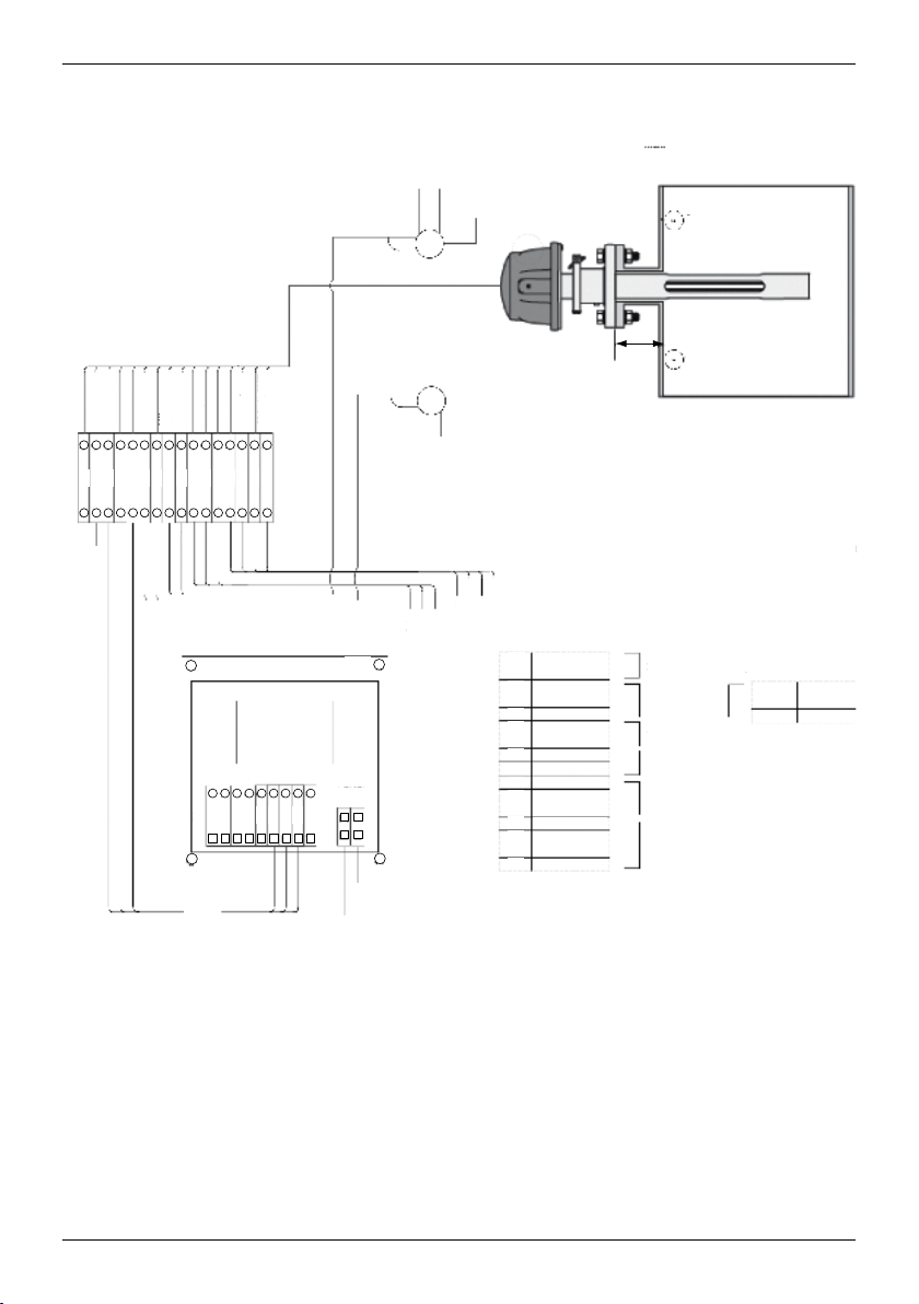
2 Before the installation
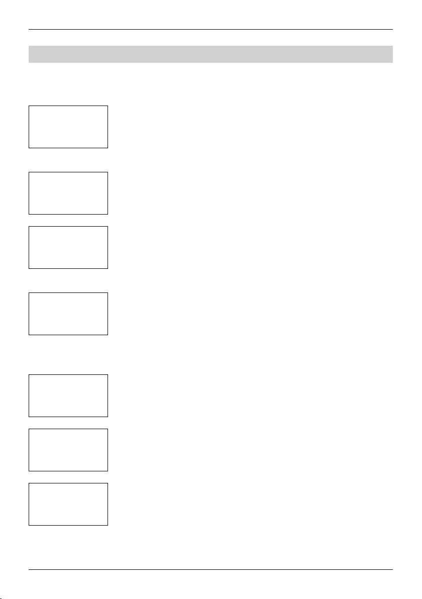
Flange placement
)
"
60 cm (23.6
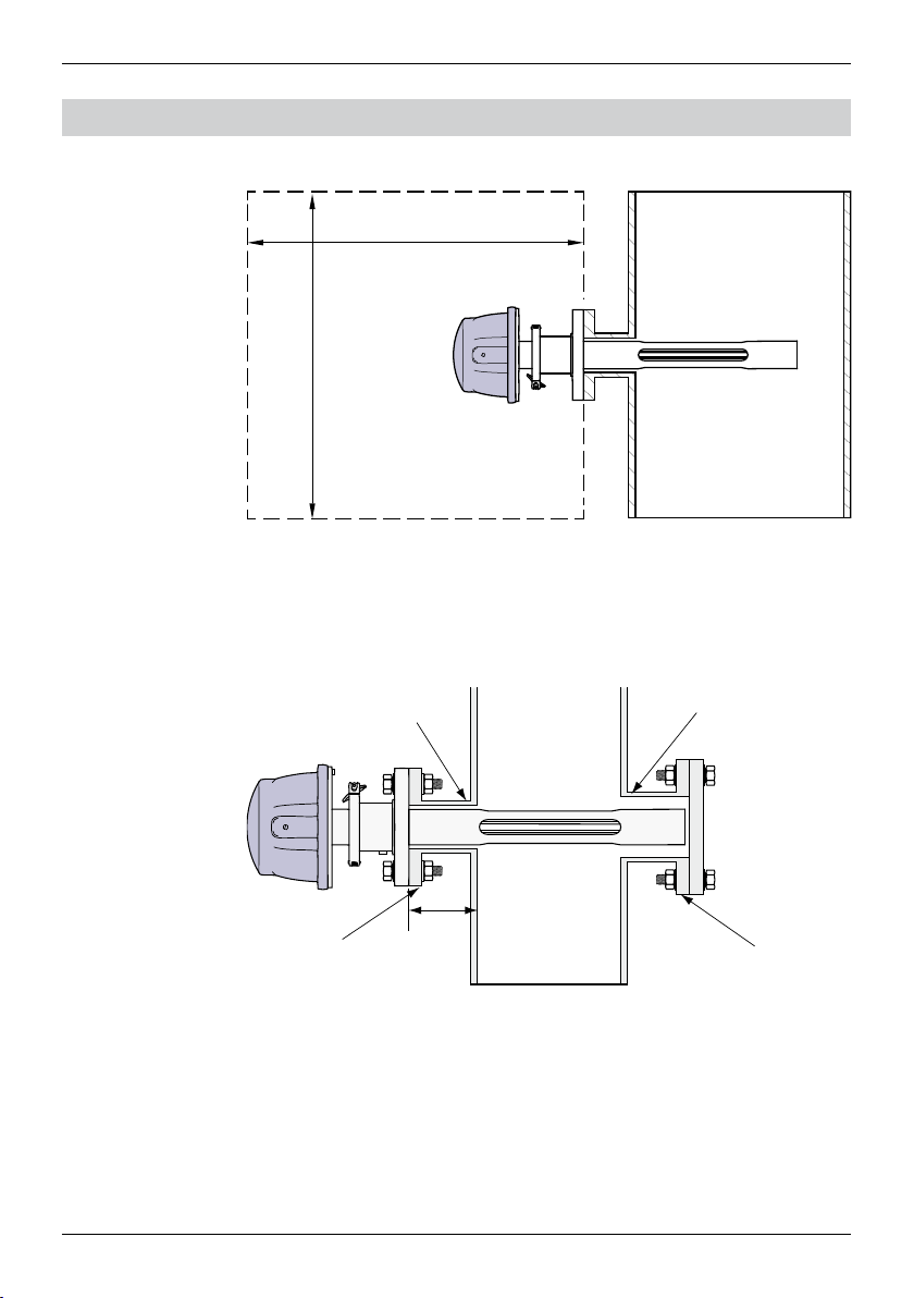
The TDL head should be easily accessible. A person should be able to stand in
front of it and adjust the M16 xing bolts using two standard spanners. There
should be at least 60 cm free space measured from the ange xed to the stack
and outwards as shown below.
60 cm (23.6")
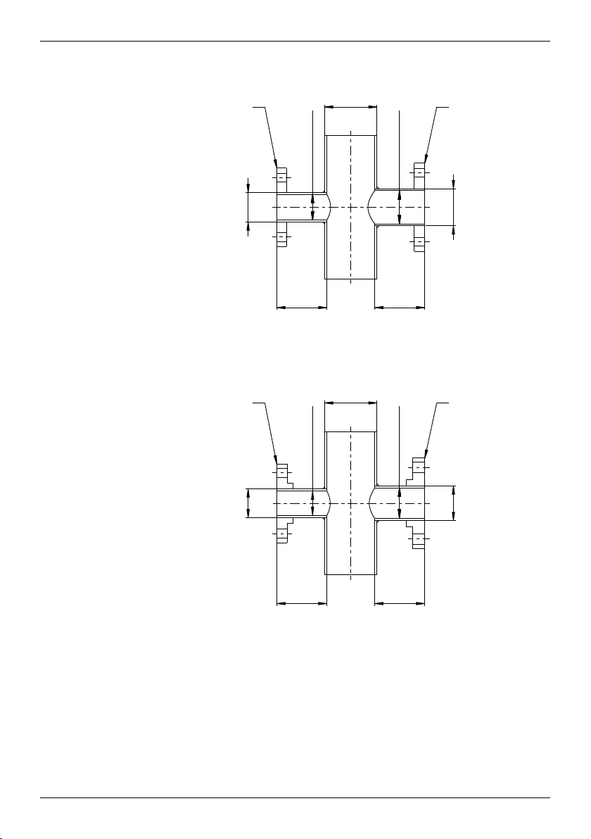
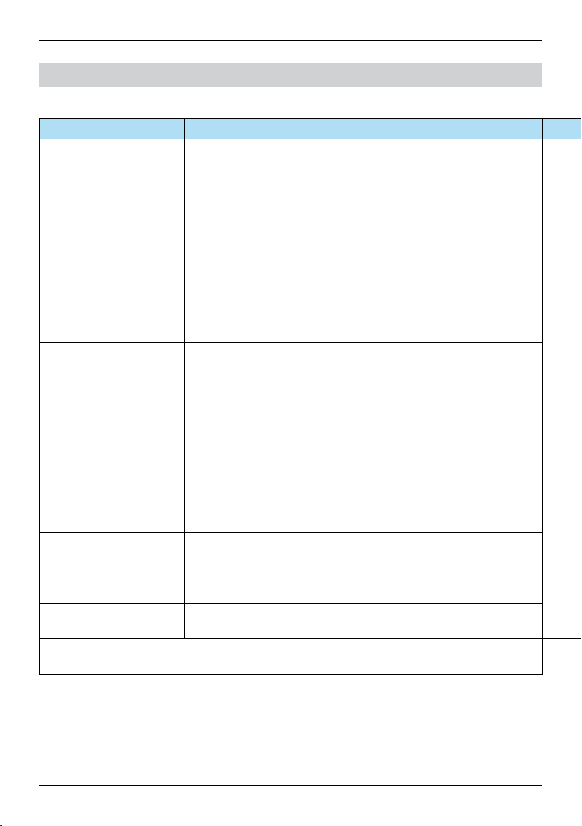
Flange requirements
min. clearance: 61,5 mm
(schedule 40)
DIN 50 or ANSI 2"
min. clearance: 77,5 mm
(schedule 80)
100 mm
(4")
DIN 65 or ANSI 2½"
7
Page 8
Quick Setup Guide TDL GPro™ 500
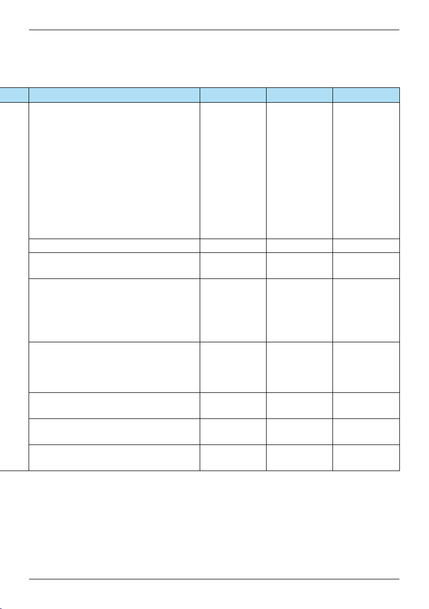
DIN
DN50/PN25 DN65/PN25
DN 50
100 mm 100 mm
DN100
min. Ø 54 mm
min. Ø 67 mm
DN65
ANSI
4"
min. 2.12"
2"
min. 2.64"
ANSI 2.5"/300 lbsANSI 2"/300 lbs
2.5"
4" 4"
When deciding the placement of the GPro™ 500 TDL in the process, we recom-
Flow conditions at measuring point
mend a minimum of 5 stack diameters of straight duct before and 3 stack diameters of straight duct after the point of measure.
This will lead to laminar ow conditions which is favorable for stable measurement conditions.
8
Page 9

Quick Setup Guide TDL GPro™ 500
Purging
1 Purge gas inlet for instrument side (6 mm or ¼" tube tting).
2 Purge gas inlet for process side (must have a check valve).
3 Purge gas outlet for instrument side (6 mm or ¼" tube tting).
4 Process gas ow.
5 Region that denes the boundaries of the effective path length.
0…1 L /min
0…10 L /min
RotameterPressure regulator
WARNING
Always start purging at maximum flow before starting the process.
WARNING
Purging must always be switched on in order
to avoid dust deposition onto the optical surfaces.
WARNING
Do not remove and / or disassemble the purge gas inlet for processes (2).
If disassembled, the PED pressure certificate is void.
WARNING
Do not connect instrument and process side purging in series, otherwise
when disassembling the sensor heat the probe purging will stop.
9
Page 10

Quick Setup Guide TDL GPro™ 500
Purging
with
thermalbarrier
Purging configuration
1 Purge gas inlet for thermal barrier (6 mm or ¼" tube tting)
2 Purge gas outlet for thermal barrier (6 mm or ¼" tube tting)
3 Purge gas inlet for process side (Must have a check valve)
4 Mandatory check valve (to be supplied by the user)
21 4
3
WARNING
The purge gas for the thermal barrier must always be turned on
when the process is running in order to protect the sensor head
from permanent damage.
10
WARNING
The failure of the instrument side and thermal barrier purging
system must trigger an alarm. This alarm has to be implemented
in th DCS ny the user.
Page 11
Quick Setup Guide TDL GPro™ 500
Grounding
andwiring(ATEX)
External earth point
for > 4 mm
(M6 × 12)
2
cables
Exernal earth point.
11
Page 12

Quick Setup Guide TDL GPro™ 500
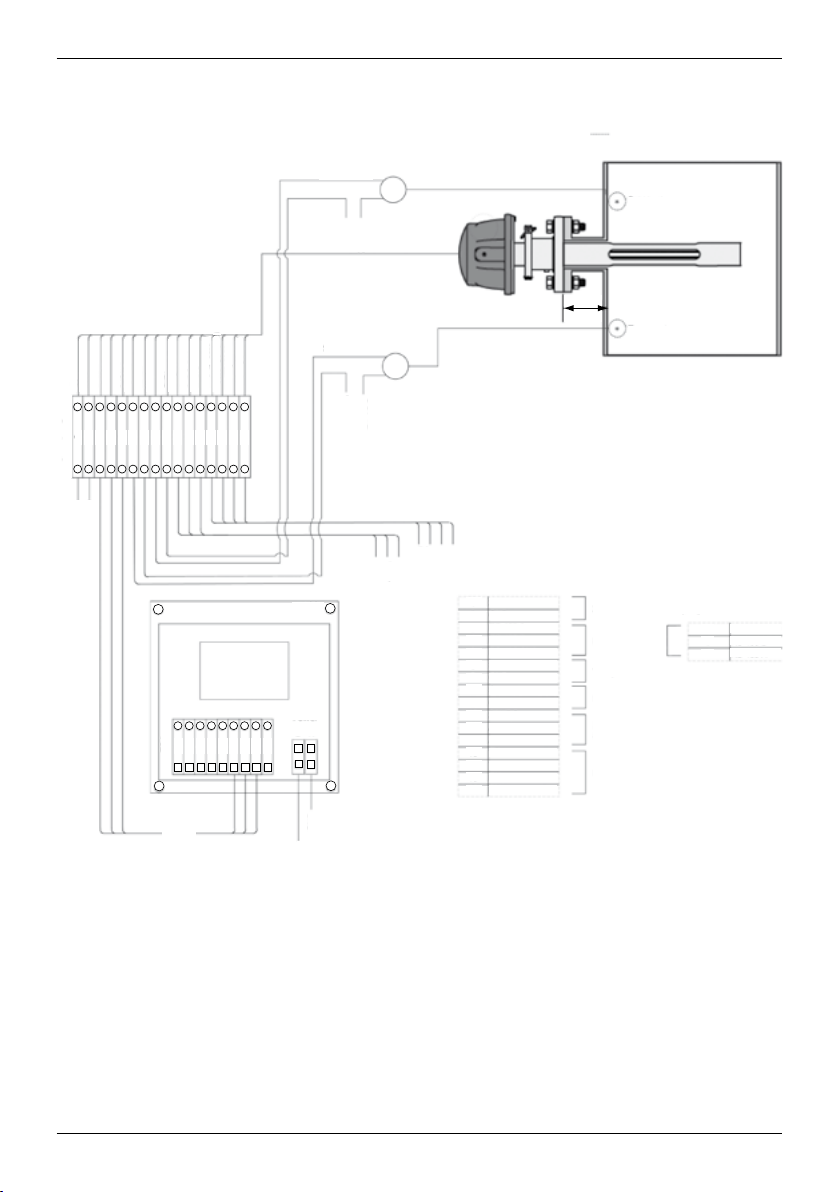
RS-485 A
Activeanaloginputs(ATEXVersion)
ACTIVE ANALOG INPUTS
24 VDC
User-provided
GND
Red
Blue
Junction Box
GND
24 VDC
Green
Yellow
Brown
+
Purple
+
xT
–
100 mm
+
xT
Power
L N
M400
–
24 VDC
Analog
Outputs
GND
Ethernet
1
24 VDC
GND
2
3
RS-485 A
RS-485 B
4
5
RS-485 GND
6
+Ain 1 4…20 mA
7
–Ain 1 4…20 mA
8
+Ain 2 4…20 mA
9
–Ain 2 4…20 mA
10
24 VDC
11
Aout 1
Aout 2
12
13
TX+
14
TX–
15
RX+
16
RX–
Black
Pink
Grey
Red/Blue
Grey/Pink
White
White/Yellow
Yellow/Brown
White/Green
Brown/Green
987654321
+
–
–
16151413121110
TB4
987654321
Pressure
(4")
Temperature
24 VDC Power 0.2 A (5W)
M400 TB4
Temperature sensor
Pressure sensor
2x 4…20 mA
passive analog outputs
Ethernet
6
7
8
RS-485 GND
RS-485 B
RS-485 A
12
RS-485
GND
20 – 30 VDC or
100 – 230 VAC +/– 10%
Page 13

Quick Setup Guide TDL GPro™ 500
Looppoweredanaloginputs(ATEX)
User-provided
Red
Blue
Junction Box
GND
24 VDC
Green
Yellow
Brown
Purple
Black
SENSOR IN
xT
GND
24 VDC
100 mm
(4")
Pressure
Temperature
SENSOR IN
xT
Pink
Grey
Red/Blue
Grey/Pink
White
White/Yellow
Yellow/Brown
White/Green
Brown/Green
GND
987654321
TB4
16151413121110
M400
Power
L N
987654321
24 VDC
Analog
Outputs
Ethernet
1
2
3
4
5
6
7
8
9
10
11
12
13
14
15
16
24 VDC
GND
RS-485 A
RS-485 B
RS-485 GND
Sensor In
GND
Sensor In
GND
24 VDC
Aout 1
Aout 2
TX+
TX–
RX+
RX–
24 VDC Power 0.2 A (5W)
M400 TB4
Temperature sensor
Pressure sensor
2x 4…20 mA
passive analog outputs
Ethernet
6
7
8
RS-485 GND
RS-485 B
RS-485 A
RS-485
GND
20 – 30 VDC or
100 – 230 VAC +/– 10%
WARNING
All openings have to be closed with certified cable glands
or blocking plugs of the same degree of certification as the GPro™ 500.
WARNING
It is essential that you observe all provided information
and warnings. The system must be closed and grounded
before switching on the system.
13
Page 14
Quick Setup Guide TDL GPro™ 500
Groundingandwiring(FM)
External earth point
for > 4 mm
(M6 ×12)
2
cables
Exernal earth point.
Protective grounding
Material: chromated AISi7Mg0.3
Size: M6 × 12 mm
Protective grounding.
14
2 options for inner protective grounding
Material: 1.4404 (AISI 316L)
Size: M4 × 6 mm
Hex cap screw
Connect with 4 mm2 cable
Page 15
Quick Setup Guide TDL GPro™ 500
RS-485 A
Activeanaloginputs(FMVersion)
ACTIVE ANALOG INPUTS
24 VDC
User-provided
GND
Red
Blue
Junction Box
GND
24 VDC
Green
Yellow
Brown
+
Purple
+
xT
–
100 mm
+
xT
Power
L N
M400
–
24 VDC
Analog
Outputs
GND
Ethernet
1
24 VDC
GND
2
3
RS-485 A
RS-485 B
4
5
RS-485 GND
6
+Ain 1 4…20 mA
7
–Ain 1 4…20 mA
8
+Ain 2 4…20 mA
9
–Ain 2 4…20 mA
10
24 VDC
11
Aout 1
Aout 2
12
13
TX+
14
TX–
15
RX+
16
RX–
Black
Pink
Grey
Red/Blue
Grey/Pink
White
White/Yellow
Yellow/Brown
White/Green
Brown/Green
987654321
+
–
–
16151413121110
TB4
987654321
Pressure
(4")
Temperature
24 VDC Power 0.2 A (5W)
M400 TB4
Temperature sensor
Pressure sensor
2x 4…20 mA
passive analog outputs
Ethernet
6
7
8
RS-485 GND
RS-485 B
RS-485 A
RS-485
GND
20 – 30 VDC or
100 – 230 VAC +/– 10%
15
Page 16
Quick Setup Guide TDL GPro™ 500
Looppoweredanaloginputs(FMVersion)
User-provided
Red
Blue
Junction Box
GND
24 VDC
Green
Yellow
Brown
Purple
Black
SENSOR IN
xT
GND
24 VDC
100 mm
(4")
Pressure
Temperature
SENSOR IN
xT
Pink
Grey
Red/Blue
Grey/Pink
White
White/Yellow
Yellow/Brown
White/Green
Brown/Green
GND
987654321
TB4
16151413121110
M400
Power
L N
987654321
24 VDC
Analog
Outputs
Ethernet
1
2
3
4
5
6
7
8
9
10
11
12
13
14
15
16
24 VDC
GND
RS-485 A
RS-485 B
RS-485 GND
Sensor In
GND
Sensor In
GND
24 VDC
Aout 1
Aout 2
TX+
TX–
RX+
RX–
24 VDC Power 0.2 A (5W)
M400 TB4
Temperature sensor
Pressure sensor
2x 4…20 mA
passive analog outputs
Ethernet
6
7
8
RS-485 GND
RS-485 B
RS-485 A
16
RS-485
GND
20 – 30 VDC or
100 – 230 VAC +/– 10%
Page 17
Quick Setup Guide TDL GPro™ 500
GPro™ 500 cables
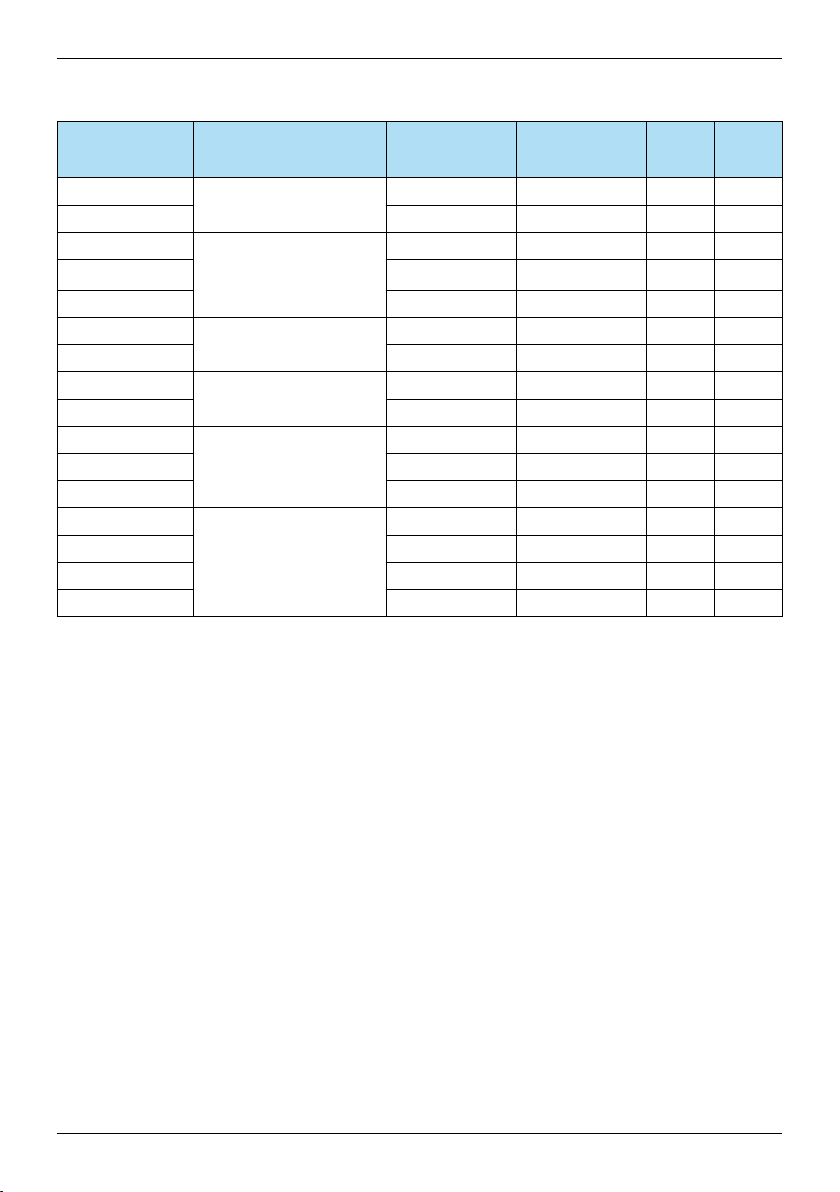
Signal Description Cable no. Color TB1 TB2
Junction Box Pin no Pin no
Power + 24 V
GND (Power) 2 Blue 2
Power 24 V, 5 W
RS 485 A
RS 485 B 4 Yellow 4
Interface M400
(RS 485)
1 Red 1
3 Green 3
RS 485 GND 5 Brown 5
4...20 mA pos
4...20 mA neg 7 Black 7
4...20 mA pos
4...20 mA neg 9 Grey 9
+ 24 V
Out 1 11
Out 2 12 White 12
Current input
temperature
Current input
pressure
Direct anolog output
(2 3 4 … 20 mA)
(optional)
TX+
TX– 14
RX+ 15
Ethernet interface
for communication
with PC
RX– 16
6 Purple 6
8 Pink 8
10
Red / Blue 10
Grey / Pink 11
13
White / Yellow 1
Yellow / Brown 2
White / Green 3
Brown / Green 4
17
Page 18
Quick Setup Guide TDL GPro™ 500
TB1
Pin 1
Pin 4
Connections on motherboard in the sensor head.
Note:ThesensorheadcoverofATEXversionshouldneverbeen
opened,asthiswillinvalidatetheATEXcertification.
TB2
Pin 1
Pin 12
Connections on IO board in the sensor head.
WARNING
All openings have to be closed with certified cable glands
or blocking plugs of the same degree of certification as the GPro™ 500.
WARNING
It is essential that you observe all provided information
and warnings. The system must be closed and grounded
before switching on the system.
18
Page 19
Quick Setup Guide TDL GPro™ 500
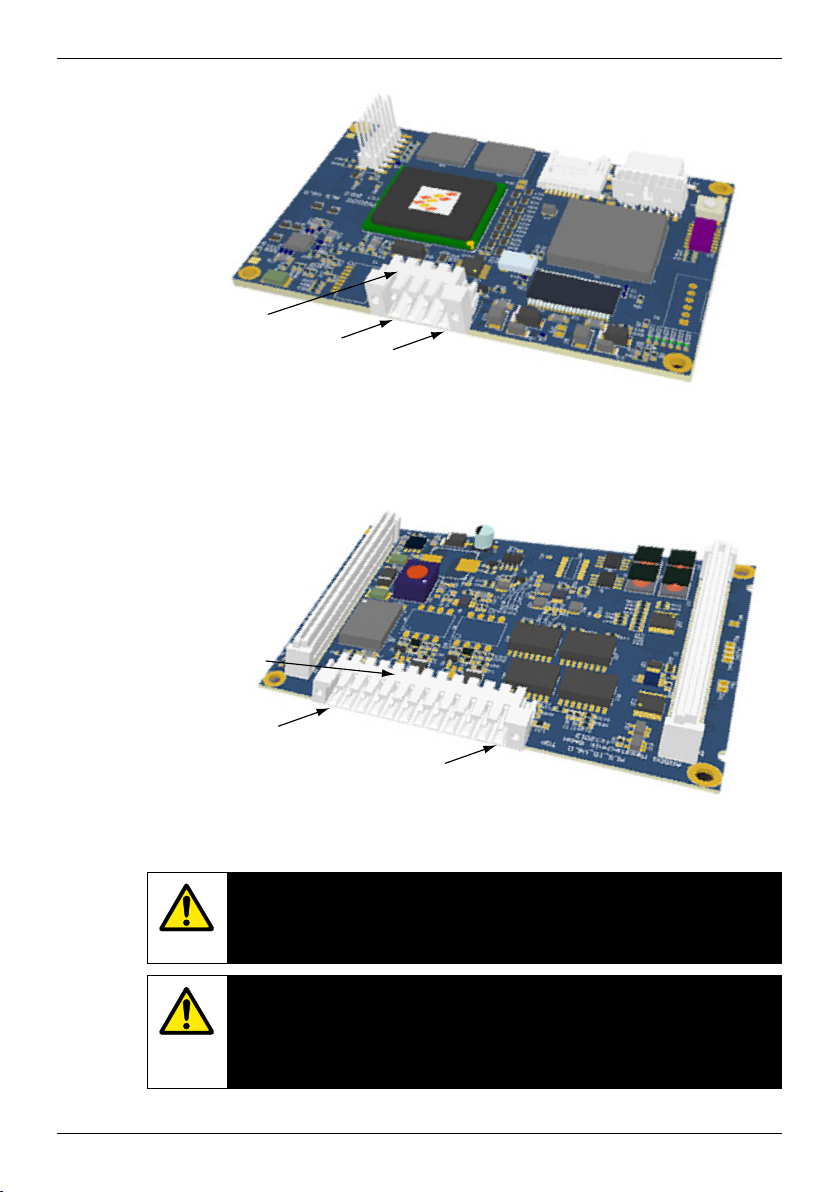
Cable connections
inM400
USB
3
1 2 3 4 5 6 7 8 9 1 2 3 4 5 6 7 8 9 1 2 3 4 5 6 7 8 9
TB1
141 2 3 4 5 6 7 8 9 10111213
TB2 TB3 TB4
1 Connection terminal for the power cable
2 TB4 – connection terminal for the GPro™ 500
3 TB1 – connection terminal for the relays.
These can be congured with the M400.
- +
N L
POWER
1
2
19
Page 20
Quick Setup Guide TDL GPro™ 500
3 Installation
GeneralSetup(appliesforallparameters)
(PATH: Menu / Quick Setup)
While in Measurement mode press the [MENU] key to bring up the Menu selec-
20.9 %V O
25.0 °C
MENU
Quick Setup
Please select the type of Sensor:
A
A
Channel Select=ISM
Parameter=Auto
6.0 pH
25.0 °C
2
tion. Select QUICK SETUP and press the [ENTER] key.
Display Convention:
u
1st line on display → a 3rd line on display
2nd line on display → b 4th line on display
→
→
c
d
Select the units of measurement for a and b. Only lines a and b can be congured in Quick Setup. Go to the Conguration Menu to congure lines c and d.
Channel Selection
Analog: For conventional analog sensors (will be displayed on channel “A”).
ISM: For ISM sensors (will be displayed on channel ”B”).
u
Please select the parameter requirement:
The choice of parameter depends on the level of transmitter. If an ISM sensor is
selected, the setting “Auto” means, all possible ISM sensors will be recognized
and accepted. If a special parameter is chosen, only this parameter will be
recognized and accepted on the transmitter.
Calibration
The GPro 500 is calibrated at the factory and does not require calibration at
installation & Startup.
TDLInstallation
(path: Quick Setup / TDL / Installation)
While in measurement mode press the key [MENU] . Press the m or . key to
B
20.9 %V O
B
20.9 %Trm
MENU
Quick Setup
In this mode, the current live value of the % transmission is displayed during
B
20.9 %V O
B
20.9 %Trm
Transmission Signal
021 %
2
select the TDL and then the Installation menu item.
u
2
5 minutes until it automatically returns to the Measurement mode. Use this
value to rotate the blue sensor head attached with a loose clamp connection on
u
to the probe until the maximum transmission is found. In this position, and
secure the blue sensor head into position and tighten the clamp.
20
Page 21
Quick Setup Guide TDL GPro™ 500
TDLCommissioning(path: Quick Setup / TDL / Commissioning)
B
20.9 %V O
B
20.9 %Trm
–TDL
O
2
Commissioning
2
While in measurement mode press the key [MENU] . Press the m or . key to
select the TDL and then the Commissioning menu item.
u
First, select the type of pressure compensation selected:
– External: current external pressure value coming from a pressure transducer
of 4.. 20 mA analog output
– Fixed: pressure compensation uses a xed value to be set manually.
Note: if this pressure compensation mode is selected, a considerable gas concentration measurement error resulting from a nonrealistic pressure value can take place.
If External compensation is selected, then the minimum (4 mA) and maximum
B
20.9 %V O
B
20.9 %Trm
Pressure=External
2
(20 mA) analog output signals from the pressure transducer must be mapped
to the corresponding Analog input of the TDL. Key in the minimum and maxi-
u
mum values of the pressure in the following units:
– hPa – mmHg – mbar
– psi – kPa
In general, METTLER TOLEDO recommends the use of absolute pressure trans-
B
20.9 %V O
B
20.9 %Trm
Ain 4 mA = 940.0 mbar
Ain 20 mA = 2000. mbar
2
ducers for more accurate signal compensation over a broad pressure range.
If, however, small pressure variations around atmospheric pressure are to be
u
expected, relative pressure sensors will produce better results; but the variations
of the underlying barometric pressure will be ignored.
For relative pressure sensors, the minimum and maximum values must be
mapped so that the TDL can interpret the analog pressure signal as “absolute”,
i.e. a xed barometric pressure of 1013 mbar (for example) has to be added to
the mapped values.
If Fixed compensation is selected, the xed pressure value with which the mea-
B
20.9 %V O
B
20.9 %Trm
Pressure=fixed
B
20.9 %V O
B
20.9 %Trm
Pressure=1013. mbar
If External compensation is selected, then the minimum (4 mA) and maximum
B
20.9 %V O
B
20.9 %Trm
Temperature=External
2
surement signal will be calculated has to be keyed in manually. For the xed
pressure, the following units can be used:
u
– hPa – mmHg – mbar
– psi – kPa
2
u
2
(20 mA) analog output signals from the temperature transducer must be
mapped to the corresponding Analog input of the TDL. Key in the minimum and
u
maximum values of the temperature in °C.
21
Page 22
Quick Setup Guide TDL GPro™ 500
B
20.9 %V O
B
20.9 %Trm
Ain 4 mA = 0.000 °C
Ain 20 mA = 250_0 °C
If Fixed compensation is selected, the xed temperature value with which the
B
20.9 %V O
B
20.9 %Trm
Temperature=Fixed
B
20.9 %V O
B
20.9 %Trm
Temperature=320.0 °C
Last, select the initial optical path length corresponding to the probe length in-
B
20.9 %V O
B
20.9 %Trm
Pathlength=00200 mm
2
u
2
measurement signal will be calculated has to be keyed in manually. For the xed
temperature, only °C can be used.
u
2
u
2
stalled:
– 290 mm probe: 200 mm
u
– 390 mm probe: 400 mm
– 590 mm probe: 800 mm
This initial value is valid when instrument purging on the instrument and on the
process side is running. Depending on the process conditions and after the
optimum of the process purging ow has been found (see next chapter), this
value may have to be slightly adapted.
22
Page 23
Quick Setup Guide TDL GPro™ 500
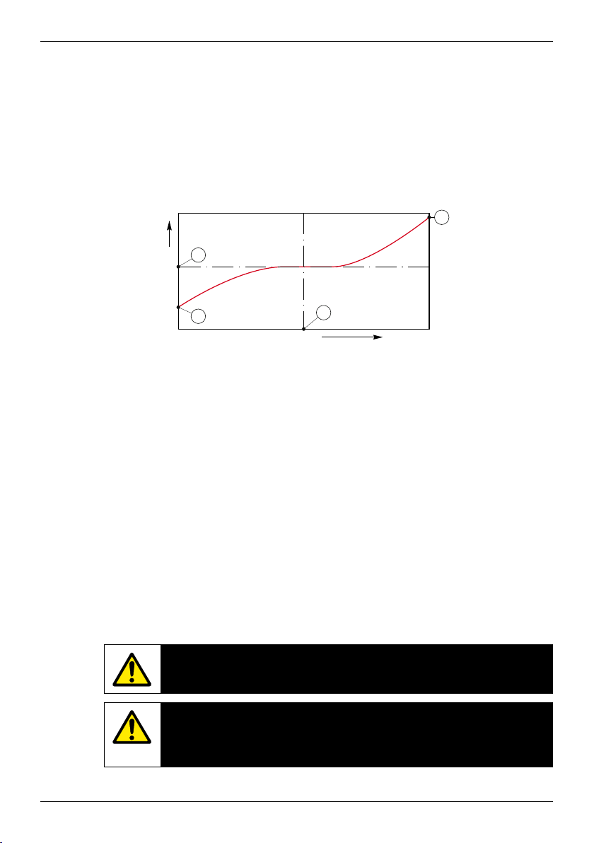
Setting the correct
The ow rate of the purging will affect the effective path length and conse-
process side purging
quently the measurement value.
Therefore the following procedure should be used. Start with a very high ow
rate and gradually decrease it. The measurement value will then start at a low
value and increase with decreasing purge ow. At some point it will level out
and stay constant for a while and then again start increasing. Choose a purge
ow in the middle of the constant region.
2
1
Inecreased reading
Decreasing purge flow
Optimizing the purge ow
On the x-axis there is purge ow and on the y-axis there is the instrument concentration reading.
1 Concentration reading with high purge ow. The path length is now shorter
than the effective path length since the purge tubes is completely lled with
purging gas and some of the purging gas is owing into the measurement
path.
2 Concentration reading with optimized purge ow. The path length is now
equal to the effective path length since the purge tubes are completely lled
with purge gas. See the illustration below.
3 Concentration reading with no purge ow. The path length is now equal to
the nominal path length since the probe is completely lled with process
gas.
4 The optimized purge ow.
3
4
WARNING
Always start purging at maximum flow before starting the process.
WARNING
Purging must always be switched on in order
to avoid dust deposition onto the optical surfaces.
23
Page 24
Quick Setup Guide TDL GPro™ 500
4 VericationandMaintenance
One-pointcalibrationforTDLgassensors
Enter calibration mode as described in section 7.1 “Enter Calibration Mode”.
B
20.9 %V O
B
25.0 °C
Calibrate Sensor
Channel B TDL
Select 1 point as calibration type.
B
20.9 %V O
H
25.0 °C
TDL Calibration
Type = 1 Point
Enter values for the effective temperature and pressure values of the gas used
B
20.9 %V O
25.0 °C
Pressure = 1013 hPa
Temperature = 23.00 °C
Place the sensor in the calibration gas (e.g. air). Press [ENTER].
B
20.9 %V O
25.0 °C
Press ENTER when
Sensor is in Gas
2
A one-point calibration of gas sensors is always a slope (i.e. with air) calibration. A one point slope calibration is done in air or any other calibration gas with
u
dened gas concentration.
2
Press [ENTER].
u
2
for calibration. When using the calibration tube for calibration, use values measured manually for the gas present in the calibration tube.
u
Adjust the optical path length for your individual system.
2
Depending on the used drift control (see chapter 8.2.3.5) one of the two following modes is active.
u
ProcesscalibrationforTDLgassensors
Enter calibration mode as described in section 7.1 “Enter Calibration Mode”.
B
12.1 %V O
B
25.0 °C
Calibrate Sensor
Channel B Oxygen
Select Process as the calibration type.
B
12.1 %V O
25.0 °C
TDL Calibration
Type = Process
Take a sample and press the [ENTER] key again to store the current measuring
B
12.1 %V O
B
25.0 °C
Press ENTER to Capture
=0.0000 V% O2 u
B O
2
2
A process calibration of gas sensors is always a slope calibration.
u
2
Press [ENTER]
u
2
value. To show the ongoing calibration process, A or B (depending on the channel) is blinking in the display.
After determining the concentration value of the sample press the
c
key again
to proceed with the calibration.
24
Page 25

Quick Setup Guide TDL GPro™ 500
150 mm (5.91")
Enter the concentration value of the sample then press the [ENTER] key to start
B
12.1 %V O
B
25.0 °C
B Point1 = 56.90 %sat
= 57.1 %air u
B O
2
After the calibration the slope ”S” is displayed.
B
12.1 %V O
B
25.0 °C
S=– 0.070 nA Z=0.0000 nA
O
2
Save Adjust
2
the calculation of the calibration results.
2
In case of a successful calibration, the calibration values are stored in the cal
history and taken over (Adjust), stored in the cal history and not taken over
u
(Calibrate) or discarded (Abort).
If ”Adjust” or ”Calibrate” are chosen, the message ”Calibration successful” is
displayed. The M400 returns to the measuring mode.
Calibration using a calibration cell
For a more accurate calibration the calibration cell can be used. Doing this the
TDL (the units head) needs to be removed from the probe. Then it has to be
mounted on the calibration cell according to the illustration below. Before calibration is started new values for path length, temperature and pressure have to
be entered on M400. Then the calibration gas is owed through the calibration
cell and the calibration is done in the calibration menu of M400.
During calibration with the calibration cell the process is still sealed and no
extra precautions need to be taken.
Calibration cell.
EPL
2 × 100 mm (3.94")
104,6 mm (4.12")
25
Page 26
Quick Setup Guide TDL GPro™ 500
5 Error messages
Message Comment Action Source Relay State Mapping
No sensor on channel 3 The M400 is unable to detect any of the ISM sensor(s) it can identify.
If no sensor is found it will disply the message NO SENSOR DETECTED
Signal Processing Failed Fitting of the line proles failed. Send unit back to METTLER TOLEDO TDL Fault Software error
Laser Source Error The laser wavelength has shifted. Readjustment of the laser tempera-
ture necessary
Bad Signal Quality Transmission lower than 5% threshold Clean corner cube and process window.
Flashcard Error Missing or bad calibration and / or database data Perform a calibration with the calibration
Pressure Input Error Pressure reading out of extended range: 0.6 bara < P < 8 bara
4 – 20 mA input error: 4 mA > P > 20 mA
Temperature Input Error Pressure reading out of extended range: –20°C<T<1000°C
4 – 20 mA input error: 4 mA > P > 20 mA
Conguration Mode Ethernet port in use: diagnostic or conguration in progress Disconnect Ethernet cable TDL Maintenance
The GPro™ 500 error messages can be found in the M400 under the following path:
Menu ➝ Service ➝ Diagnostics ➝ TDL ➝ Messages
26
Page 27
Quick Setup Guide TDL GPro™ 500
– This is the initial message after Power on.
M400 Fault B disconnected
– Wait for the GPro™ 500 to fully boot.
– Check if the GPro™ 500 is powered and
wait until the system is fully started.
– Check the RS485 wiring of the
GPro™ 500 to the M400
– Check with the MT-TDL software and the
Ethernet port if the system is running
correctly.
– If timeout still occurs after 60 s, send unit
back to METTLER TOLEDO.
Send unit back to METTLER TOLEDO TDL Fault System error
TDL Fault System error
Check the gasket between TDL and probe.
Rotate TDL on the probe to maximize Trans-
mission.
Reduce the dustload in the process.
TDL Fault Software error
tube.
If still not successful, send unit back to
METTLER TOLEDO for Flashcard exchange.
Check external pressure sensor and mapping TDL Maintenance
System error
request
Check external temperature sensor and
mapping
TDL Maintenance
request
System error
Software error
request
27
Page 28

Page 29

Quick Setup Guide TDL GPro™ 500
GPro™ 500
Quick Setup-Leitfaden
Inhaltsverzeichnis
1 Vorbereitung 31
Lieferumfang 31
Anforderungen vor Ort 31
Umgebungs-bedingungen 31
Außerdem erforderlich 31
Optionales Zubehör 32
2 Vor der Installation 33
Montageort für Flansch 33
Anforderungen an den Flansch 33
Strömungs-verhältnisse anderMessstelle 34
Spülen 35
Spülen mit Wärmeschutz 36
Erdung und Verdrahtung (ATEX) 37
Aktive Analogeingänge (ATEX-Ausführung) 38
Schleifengespeiste Analogeingänge (ATEX-Ausführung) 39
Erdung und Verdrahtung (FM) 40
Aktive Analogeingänge (FM-Ausführung) 41
Schleifengespeiste Analogeingänge (FM-Ausführung) 42
GPro™ 500 Kabel 43
Kabelanschlüsse im M400 45
German
3 Installation 46
Allgemeines Setup (gilt für alle Parameter) 46
Kanalwahl 46
Kalibrierung 46
TDL Installation 46
Einstellung der korrekten Spülung der Prozessseite 49
4 Verifizierung und Wartung 50
Einpunktkalibrierung von TDL-Gassensoren 50
Prozesskalibrierung für TDL-Gassensoren 50
Kalibrierung mit einer Kalibrierzelle 51
5 Fehlermeldungen 52
29
Page 30

Quick Setup Guide TDL GPro™ 500
30
Page 31

Quick Setup Guide TDL GPro™ 500
1 Vorbereitung
– GPro™ 500 Analysator mit durchstimmbarem Diodenlaser– GPro™ 500 Analysator mit durchstimmbarem Diodenlaser GPro™ 500 Analysator mit durchstimmbarem DiodenlaserGPro™ 500 Analysator mit durchstimmbarem Diodenlaser
Lieferumfang
–
1 Sicherheitshinweise
–
1 Dokumentations-CD mit Bedienungsanleitung und MT-TDL Software Suite.
– 24 VDC, 5 W für die Stromversorgung des GPro™ 500– 24 VDC, 5 W für die Stromversorgung des GPro™ 500 24 VDC, 5 W für die Stromversorgung des GPro™ 50024 VDC, 5 W für die Stromversorgung des GPro™ 500
Anforderungen vor Ort
–
110 / 220 VAC für die Stromversorgung des M400
– Spülgas, > 99,7% Reinheit (empfohlener Mindestwert), 0,5…5l/min.
Die Reinheitsanforderungen sind:
normgemäß nach ISO 8573.1, Klasse 2–3, analog zur Geräteluft.
Für Sauerstoff TDL kann Stickstoff oder jedes andere «sauerstofffreie»
saubere und trockene Gas verwendet werden.
− 20 bis + 55 °C (− 4 bis + 131 °F) im laufenden Betrieb
Umgebungsbedingungen
• 1 M400 T3 Transmitter (Bestell-Nr. 52121350)
Außerdem
•
erforderlich
1 Ethernetkabel CAT5
•
RS485-Kabel (< 250m)
• 1 Laptop (WinXP / 7 / 8) mit installierter MT-TDL Software
• Flachdichtung 82,14 mm 3 3,53 mm
• Absperrventil
•
2 Gabelschlüssel (Schraubenschlüssel) für Schrauben M16
•
1 Imbusschlüssel 5 mm für die Klemmschrauben an den Flanschen
und Tx-Deckelschrauben
•
1 Imbusschlüssel 3 mm für die Schrauben der
RS232-Schnittstellenabdeckung
•
2 Flachschlüssel für Swagelok-Rohrverschraubungen
•
1 Schlitz-Schraubendreher (2,5 mm) für die elektrischen Anschlüsse
•
1 Schlitz-Schraubendreher (6mm) oder Kreuzschraubendreher (Nr. 2)
für die Rx-Deckelschrauben
•
Rollgabelschlüssel (Schraubenschlüssel) für die Spülgasanschlüsse
•
Drehmomentschlüssel für die FM-Ausführung
31
Page 32

Quick Setup Guide TDL GPro™ 500
Optionales Zubehör
Zubehör Bestellnummer
Wärmeschutz 30 034 138
Anschlussbox 30 034 149
Spülbox für M400 Ex d 30 034 148
Kalibrierkit 30 034 139
O
2
Kit Flachdichtung ST 30 080 914
Kit Flachdichtung HT (Graphit) 30 080 915
Kabel GPro 500 ATEX, FM 5 m 30 077 735
Kabel GPro 500 ATEX, FM 15 m 30 077 736
Kabel GPro 500 ATEX, FM 25 m 30 077 737
32
Page 33

Quick Setup Guide TDL GPro™ 500
2 Vor der Installation
Montageort für Flansch
Der TDL-Kopf muss leicht zugänglich sein. Eine Person muss vor dem Sensor
stehen können und mit zwei normalen Gabelschlüsseln die M16 Befestigungsschrauben erreichen. Um den quer in die Leitung eingebauten Flansch herum
müssen mindestens 60 cm Platz sein, wie unten dargestellt.
60 cm (23.6")
)
"
60 cm (23.6
Anforderungen an den Flansch
Mindestabstand: 61,5mm
(Schedule 40)
DIN 50 oder ANSI 2"
Mindestabstand: 77,5mm
(Schedule 80)
100 mm
(4")
DIN 65 oder ANSI
2½"
33
Page 34

Quick Setup Guide TDL GPro™ 500
DIN
DN50/PN25 DN65/PN25
DN 50
100 mm 100 mm
DN100
min. Ø 54 mm
min. Ø 67 mm
DN65
ANSI
4"
min. 2.12"
2"
min. 2.64"
ANSI 2.5"/300 lbsANSI 2"/300 lbs
2.5"
4" 4"
Bei der Wahl des Einbauorts des GPro™ 500 TDL in den Prozess ist darauf zu Bei der Wahl des Einbauorts des GPro™ 500 TDL in den Prozess ist darauf zu
Strömungsverhältnisse
anderMessstelle
achten, dass vor der Messstelle eine gerade Einlaufstrecke von mindestens dem
5-fachen des Leitungsdurchmessers und nach der Messstelle von mindestens
dem 3-fachen des Leitungsdurchmessers frei bleibt.
So können sich laminare Strömungsverhältnisse einstellen, die eine Voraussetzung für stabile Messbedingungen sind.
34
Page 35

Quick Setup Guide TDL GPro™ 500
Spülen
1 Spülgaseinlass Geräteseite (6mm- oder ¼"-Anschluss).
2 Spülgaseinlass Prozessseite (Absperrventil erforderlich).
3 Spülgasauslass Geräteseite (6 mm- oder ¼"-Anschluss).
4 Prozessgasuss.
5
Bereich der Grenzen der effektiven optischen Weglänge.
0 −1 l/min
0 −10 l/min
RotameterDruckregler
WARNUNG
Bevor der Prozess gestartet wird, ist der Spülgasfluss
immer auf maximalen Durchfluss einzustellen.
WARNUNG
Die Spülung muss immer aktiviert sein, um Staubablagerungen
auf den optischen Flächen vorzubeugen.
WARNUNG
Entfernen und / oder demontieren Sie keinesfalls den Spülgaseinlass auf
der Prozessseite (2). Durch Demontieren des Einlasses erlischt
die Zulassung gemäß Druckgeräterichtlinie (DGRL).
WARNUNG
Schalten Sie die Spülung des Geräts und der Prozessseite nicht
in Serie, sonst wird die Sensorspülung beim Demontieren
des Sensorkopfes angehalten.
35
Page 36

Quick Setup Guide TDL GPro™ 500
Spülen mit
W
ärmeschutz
Konfiguration beim Spülen
1
Spülgaseinlass in die thermische Barriere (6 mm- oder ¼"-Anschluss)
2
Spülgasauslass aus der thermischen Barriere (6 mm- oder ¼"-Anschluss)
3 Spülgaseinlass Prozessseite (erfordert ein Absperrventil)
4 Absperrventil vorgeschrieben (muss vom Benutzer bereitgestellt werden)
Das Spülgas für die thermische Barriere muss immer aktiviert sein,
21 4
3
WARNUNG
wenn der Prozessgasstrom aktiviert ist, um den Sensorkopf vor
dauerhafter Beschädigung zu schützen.
36
WARNUNG
Störungen im Spülsystem der Geräteseite und der thermischen Barriere
müssen zwingend einen Alarm auslösen. Dieser Alarm ist von
Anwenderseite im PLS zu implementieren.
Page 37

Quick Setup Guide TDL GPro™ 500
Erdung und
Verdrahtung
(ATEX)
Externer
Erdungspunkt
für Kabel mit
> 4 mm
(M6 × 12)
Externer Erdungspunkt
2
37
Page 38

Quick Setup Guide TDL GPro™ 500
RS-485 A
AktiveAnalogeingänge(ATEX-Ausführung)
ACTIVE ANALOG INPUTS
24 VDC
User-provided
GND
Red
Blue
Junction Box
GND
24 VDC
Green
Yellow
Brown
+
Purple
+
xT
–
100 mm
+
xT
Power
L N
M400
–
24 VDC
Analog
Outputs
GND
Ethernet
1
24 VDC
GND
2
3
RS-485 A
RS-485 B
4
5
RS-485 GND
6
+Ain 1 4…20 mA
7
–Ain 1 4…20 mA
8
+Ain 2 4…20 mA
9
–Ain 2 4…20 mA
10
24 VDC
11
Aout 1
Aout 2
12
13
TX+
14
TX–
15
RX+
16
RX–
Black
Pink
Grey
Red/Blue
Grey/Pink
White
White/Yellow
Yellow/Brown
White/Green
Brown/Green
987654321
+
–
–
16151413121110
TB4
987654321
Pressure
(4")
Temperature
24 VDC Power 0.2 A (5W)
M400 TB4
Temperature sensor
Pressure sensor
2x 4…20 mA
passive analog outputs
Ethernet
6
7
8
RS-485 GND
RS-485 B
RS-485 A
38
RS-485
GND
20 – 30 VDC or
100 – 230 VAC +/– 10%
Page 39

Quick Setup Guide TDL GPro™ 500
SchleifengespeisteAnalogeingänge(ATEX-Ausführung)
User-provided
Red
Blue
Junction Box
GND
24 VDC
Green
Yellow
Brown
Purple
Black
SENSOR IN
xT
GND
24 VDC
100 mm
(4")
Pressure
Temperature
SENSOR IN
xT
Pink
Grey
Red/Blue
Grey/Pink
White
White/Yellow
Yellow/Brown
White/Green
Brown/Green
GND
987654321
TB4
16151413121110
M400
Power
L N
987654321
24 VDC
Analog
Outputs
Ethernet
1
2
3
4
5
6
7
8
9
10
11
12
13
14
15
16
24 VDC
GND
RS-485 A
RS-485 B
RS-485 GND
Sensor In
GND
Sensor In
GND
24 VDC
Aout 1
Aout 2
TX+
TX–
RX+
RX–
24 VDC Power 0.2 A (5W)
M400 TB4
Temperature sensor
Pressure sensor
2x 4…20 mA
passive analog outputs
Ethernet
6
7
8
RS-485 GND
RS-485 B
RS-485 A
RS-485
GND
20 – 30 VDC or
100 – 230 VAC +/– 10%
WARNUNG
Alle Öffnungen sind mit zugelassenen Kabelverschraubungen oder
Verschlussstopfen zu verschließen, die über die gleichen
Zertifizierungen verfügen wie der GPro™ 500.
WARNUNG
Sämtliche in dieser Bedienungsanleitung gegebenen Informationen und
enthaltenen Warnungen sind einzuhalten. Das System muss vor der
letztendlichen Inbetriebnahme geschlossen und geerdet sein.
39
Page 40

Quick Setup Guide TDL GPro™ 500
Erdung und
Verdrahtung(FM)
Externer
Erdungspunkt
für Kabel mit
> 4 mm
(M6 × 12)
Externer Erdungspunkt
2
40
Schutzerdung
Schutzerdung
Werkstoff: AISi7Mg0,3 verchromt
Größe: M6 × 12mm
Zwei Optionen für die innere Schutzerdung
Werkstoff: 1.4404 (AISI 316L)
Größe: M4 × 6mm
Sechskantschraube
Anschluss mit Kabel 4 mm
2
Page 41

Quick Setup Guide TDL GPro™ 500
RS-485 A
AktiveAnalogeingänge(FM-Ausführung)
ACTIVE ANALOG INPUTS
24 VDC
User-provided
GND
Red
Blue
Junction Box
GND
24 VDC
Green
Yellow
Brown
+
Purple
+
xT
–
100 mm
+
xT
Power
L N
M400
–
24 VDC
Analog
Outputs
GND
Ethernet
1
24 VDC
GND
2
3
RS-485 A
RS-485 B
4
5
RS-485 GND
6
+Ain 1 4…20 mA
7
–Ain 1 4…20 mA
8
+Ain 2 4…20 mA
9
–Ain 2 4…20 mA
10
24 VDC
11
Aout 1
Aout 2
12
13
TX+
14
TX–
15
RX+
16
RX–
Black
Pink
Grey
Red/Blue
Grey/Pink
White
White/Yellow
Yellow/Brown
White/Green
Brown/Green
987654321
+
–
–
16151413121110
TB4
987654321
Pressure
(4")
Temperature
24 VDC Power 0.2 A (5W)
M400 TB4
Temperature sensor
Pressure sensor
2x 4…20 mA
passive analog outputs
Ethernet
6
7
8
RS-485 GND
RS-485 B
RS-485 A
RS-485
GND
20 – 30 VDC or
100 – 230 VAC +/– 10%
41
Page 42

Quick Setup Guide TDL GPro™ 500
SchleifengespeisteAnalogeingänge(FM-Ausführung)
User-provided
Red
Blue
Junction Box
GND
24 VDC
Green
Yellow
Brown
Purple
Black
SENSOR IN
xT
GND
24 VDC
100 mm
(4")
Pressure
Temperature
SENSOR IN
xT
Pink
Grey
Red/Blue
Grey/Pink
White
White/Yellow
Yellow/Brown
White/Green
Brown/Green
GND
987654321
TB4
16151413121110
M400
Power
L N
987654321
24 VDC
Analog
Outputs
Ethernet
1
2
3
4
5
6
7
8
9
10
11
12
13
14
15
16
24 VDC
GND
RS-485 A
RS-485 B
RS-485 GND
Sensor In
GND
Sensor In
GND
24 VDC
Aout 1
Aout 2
TX+
TX–
RX+
RX–
24 VDC Power 0.2 A (5W)
M400 TB4
Temperature sensor
Pressure sensor
2x 4…20 mA
passive analog outputs
Ethernet
6
7
8
RS-485 GND
RS-485 B
RS-485 A
42
RS-485
GND
20 – 30 VDC or
100 – 230 VAC +/– 10%
Page 43

Quick Setup Guide TDL GPro™ 500
GPro™ 500 Kabel
Signal Beschreibung Kabel-Nr. Farbe TB1 TB2
Anschlussbox Pin-Nr. Pin-Nr.
Stromversorgung
+ 24 V
GND (Stromver-
Stromversorgung 24 V,
5 W
sorgung)
RS485 A
RS485 B 4 Gelb 4
Schnittstelle M400
(RS485)
1 Rot 1
2 Blau 2
3 Grün 3
RS485 GND 5 Braun 5
4 ... 20 mA pos
4 ... 20 mA neg 7 Schwarz 7
4 ... 20 mA pos
4 ... 20 mA neg 9 Grau 9
+ 24 V
Out 1 11
Out 2 12 Weiß 12
Stromeingang
Temperatur
Stromeingang Druck
Direkter Analogausgang
(2 3 4 – 20 mA)
(optional)
TX+
TX– 14
RX+ 15
Ethernet-Anschluss für
Kommunikation mit PC
RX– 16
6 Violett 6
8 Rosa 8
10
Rot / Blau 10
Grau / Rosa 11
13
Weiß / Gelb 1
Gelb / Braun 2
Weiß / Grün 3
Braun / Grün 4
43
Page 44

Quick Setup Guide TDL GPro™ 500
TB1
Anschlüsse an der Hauptplatine im Sensorkopf
Hinweis: DieAbdeckungdesSensorkopfsdarfbeiderATEX-
Pin 1
Pin 4
Ausführung keinesfalls geöffnet werden, da sonst
dieATEX-ZertifizierungihreGültigkeitverliert.
44
TB2
Pin 1
Pin 12
Anschlüsse auf E / A-Platine im Sensorkopf
WARNUNG
Alle Öffnungen sind mit zugelassenen Kabelverschraubungen oder
Verschlussstopfen zu verschließen, die über die gleichen
Zertifizierungen verfügen wie der GPro™ 500.
WARNUNG
Sämtliche in dieser Bedienungsanleitung gegebenen Informationen und
enthaltenen Warnungen sind einzuhalten. Das System muss vor der
letztendlichen Inbetriebnahme geschlossen und geerdet sein.
Page 45

Quick Setup Guide TDL GPro™ 500
Kabelanschlüsse im M400
USB
3
1 2 3 4 5 6 7 8 9 1 2 3 4 5 6 7 8 9 1 2 3 4 5 6 7 8 9
TB1
141 2 3 4 5 6 7 8 9 10111213
TB2 TB3 TB4
1 Anschlussklemme für Stromversorgungskabel
2 TB4 – Anschlussklemme für den GPro™ 500 TB4 – Anschlussklemme für den GPro™ 500TB4 – Anschlussklemme für den GPro™ 500
3 TB1 – Anschlussklemme für die Relais.
Diese können mit dem M400 konguriert werden.
- +
N L
POWER
1
2
45
Page 46

Quick Setup Guide TDL GPro™ 500
3 Installation
AllgemeinesSetup(giltfüralleParameter)
(PFAD: Menu / Quick Setup)
20.9 %V O
25.0 °C
MENU
Quick Setup
A
A
Kanal Auswahl=ISM
Parameter=Auto
6.0 pH
25.0 °C
Drücken Sie im Messmodus die Taste [MENU], um das Menü aufzurufen.
2
Wählen Sie Quick Setup und drücken Sie die Taste [ENTER].
Zeilenbezeichnung:
u
1. Zeile des Displays
2. Zeile des Displays
➝ a 3. Zeile des Displays ➝ c
➝ b 4. Zeile des Displays ➝ d
Wählen Sie die Maßeinheiten für a und b. Es können nur die Zeilen a und b im
Quick Setup konguriert werden. Gehen Sie zum Kongurationsmenü, um die
Zeilen c und d zu kongurieren.
Kanalwahl
Bitte wählen Sie den Sensortyp:
Analog:
Für herkömmliche analoge Sensoren (werden auf Kanal «A» angezeigt).
ISM:
Für ISM-Sensoren (werden auf Kanal «B» angezeigt).
u
Bitte wählen Sie die Parameter-Anforderungen:
Die Auswahl der Parameter richtet sich nach dem verwendeten Transmitter. Wird
ein ISM-Sensor ausgewählt, bedeutet die Einstellung «Auto», dass alle ISMSensoren erkannt und akzeptiert werden. Wird ein bestimmter Parameter ausgewählt, wird nur dieser Parameter vom Transmitter erkannt und akzeptiert.
Kalibrierung
Der GPro 500 ist werksseitig kalibriert und erfordert bei Installation und Inbetriebnahme keine Kalibrierung.
TDLInstallation
(Pfad: Quick Setup / TDL / Installation)
B
20.9 %V O
B
20.9 %Trm
MENU
Quick Setup
B
20.9 %V O
B
20.9 %Trm
Transmissionssignal
021 %
46
Drücken Sie im Messmodus die Taste [MENU]. Drücken Sie die Taste m
2
oder
., um den TDL auszuwählen und anschließend den Menüpunkt
Installation.
u
In diesem Modus wird auf dem Display für fünf Minuten der aktuelle Transmis-In diesem Modus wird auf dem Display für fünf Minuten der aktuelle Transmis-
2
sionswert in Prozent angezeigt. Danach kehrt die Anzeige automatisch wieder
in den Messmodus zurück. Anhand dieses Werts können Sie den blauen Sen-
u
sorkopf drehen, der mit einer losen Klemmverbindung an dem Sensor befestigt
ist, bis Sie die maximale Transmission gefunden haben. Halten Sie den blauen
Sensorkopf in dieser Position und ziehen Sie die Klemme fest.
Page 47

Quick Setup Guide TDL GPro™ 500
B
20.9 %V O
B
20.9 %Trm
–TDL
O
2
Inbetriebnahme
B
20.9 %V O
B
20.9 %Trm
Druck=ext. Sensor
B
20.9 %V O
B
20.9 %Trm
Ain 4 mA = 940.0 mbar
Ain 20 mA = 2000. mbar
TDLInbetriebnahme(Pfad: Quick Setup / TDL / Commissioning)
2
Drücken Sie im Messmodus die Taste [MENU]. Drücken Sie die Taste m
oder
u
., um den TDL auszuwählen und anschließend den Menüpunkt Inbetrieb-
nahme.
Wählen Sie als Erstes die Art der Druckkompensation:
–
Extern: aktueller Wert des externen Drucks, der von einem Drucksensor am
Analogausgang 4 ... 20 mA eingespeist wird
– Fest: Druckkompensation verwendet einen festen Wert, der manuell ein- Fest: Druckkompensation verwendet einen festen Wert, der manuell ein-Fest: Druckkompensation verwendet einen festen Wert, der manuell ein- Druckkompensation verwendet einen festen Wert, der manuell ein-Druckkompensation verwendet einen festen Wert, der manuell ein-
gestellt wird.
Hinweis: Wird dieser Druckkompensations-Modus ausgewählt,
kann aufgrund eines unrealistischen Druckwerts ein erheblicher
Messfehler bei der Gaskonzentration auftreten.
Wird die externe Kompensation ausgewählt, müssen die minimalen (4mA) und
2
die maximalen (20 mA) Analogausgangssignale des Drucksensors dem entsprechenden Analogeingang des TDL zugeordnet werden. Geben Sie die mini-
u
malen und maximalen Druckwerte in den folgenden Einheiten ein:
–
hPa – mmHg – mbar
–
psi – kPa
Im Allgemeinen emp ehlt METTLER TOLEDO die Verwendung von Absolutdruck-Im Allgemeinen empehlt METTLER TOLEDO die Verwendung von Absolutdruck-
2
sensoren für eine genauere Signalkompensation über einen breiten Druckbereich. Wenn jedoch kleine Druckabweichungen rund um den atmosphärischen
u
Druck zu erwarten sind, erzielen Relativdrucksensoren bessere Ergebnisse. Die
Abweichungen des zugrundeliegenden barometrischen Drucks werden dabei
ignoriert.
B
20.9 %V O
B
20.9 %Trm
Druck=fester Wert
B
20.9 %V O
B
20.9 %Trm
Pressure=1013. mbar
B
20.9 %V O
B
20.9 %Trm
Temperatur=ext. Sensor
Bei Relativdrucksensoren müssen die Minimal- und die Maximalwerte so zugeordnet werden, dass der TDL das analoge Drucksignal als «absolut» interpretieren kann. Den Werten wird dabei beispielsweise ein fester barometrischer Druck
von 1013mbar zugeordnet.
Ist die feste Kompensation ausgewählt, muss der für die Berechnung des Mess-Ist die feste Kompensation ausgewählt, muss der für die Berechnung des Mess-
2
signals erforderliche feste Druckwert manuell eingegeben werden. Für den festen
Druck können die folgenden Einheiten verwendet werden:
u
–
hPa – mmHg – mbar
– psi – kPa
2
u
Wird die externe Kompensation ausgewählt, sind die minimalen (4 mA) und
2
maximalen (20 mA) Analogausgangssignale des Temperaturfühlers dem entsprechenden Analogeingang des TDL zuzuordnen. Geben Sie die Minimal- und
u
Maximalwerte der Temperatur in °C ein.
47
Page 48

Quick Setup Guide TDL GPro™ 500
B
20.9 %V O
B
20.9 %Trm
Ain 4 mA = 0.000 °C
Ain 20 mA = 250_0 °C
B
20.9 %V O
B
20.9 %Trm
Temperatur=fester Wert
B
20.9 %V O
B
20.9 %Trm
Temperatur=320.0 °C
B
20.9 %V O
B
20.9 %Trm
Opt. Weglänge=00200 mm
2
u
Ist die feste Kompensation ausgewählt, muss der für die Berechnung des Mess-Ist die feste Kompensation ausgewählt, muss der für die Berechnung des Mess-
2
signals erforderliche feste Temperaturwert manuell eingegeben werden. Die feste
Temperatur kann nur in °C eingegeben werden.
u
2
u
Zuletzt wählen Sie die optische Weglänge aus, die der installierten Sensorlänge
2
entspricht:
–
290mm Sensor: 200 mm
u
–
390mm Sensor: 400 mm
–
590mm Sensor: 800 mm
Dieser Wert ist gültig, wenn die Gerätespülung am Gerät und an der Prozessseite läuft. In Abhängigkeit der Prozessbedingungen und nachdem der optimale
Prozess-seitigen Spüldurchuss gefunden wurde (siehe nächstes Kapitel),
muss dieser Wert eventuell leicht angeglichen werden.
48
Page 49

Quick Setup Guide TDL GPro™ 500
Einstellung
Die Durchussrate des Spülgases beeinusst die effektive optische Weglänge
der korrekten
Spülung der
Prozessseite
und damit den Messwert.
Daher ist die folgende Vorgehensweise unbedingt einzuhalten! Zu Beginn mit
einer sehr hohen Durchussrate anfangen und diese schrittweise verringern. Der
Messwert ist zunächst sehr klein und steigt mit abnehmendem Spülgasuss. Bei
einem bestimmten Punkt wird er sich einpendeln und eine Zeit lang konstant
bleiben, bis er wieder zu steigen beginnt. Wählen Sie einen Spülgasuss im
mittleren Bereich der konstanten Messwertanzeige.
3
2
Messwert steigt
1
Spülgasfluss verringern
Spülgasuss optimieren
4
Auf der x-Achse ist der Spülgasuss und auf der y-Achse der vom Gerät angezeigte Messwert für die Konzentration dargestellt.
1
Messwert für die Konzentration bei hohem Spülgasuss. Die optische
Weglänge ist hier kürzer als die effektive Weglänge, weil die Spülgasleitungen komplett mit Spülgas gefüllt sind und das Spülgas in den Messweg
hineinießt.
2 Messwert für die Konzentration bei optimiertem Spülgasuss. Die optische
Weglänge ist hier gleich der effektiven Weglänge, weil die Spülgasleitungen
komplett mit Spülgas gefüllt sind.
3 Messwert für die Konzentration ohne Spülgasuss. Die optische Weglänge
ist hier gleich der nominellen Weglänge, weil der Sensor komplett mit
Prozessgas gefüllt ist.
4
Optimierter Spülgasuss.
WARNUNG
Bevor der Prozess gestartet wird, ist der Spülgasfluss
immer auf maximalen Durchfluss einzustellen.
WARNUNG
Die Spülung muss immer aktiviert sein, um Staubablagerungen
auf den optischen Flächen vorzubeugen.
49
Page 50

Quick Setup Guide TDL GPro™ 500
4 VerizierungundWartung
EinpunktkalibrierungvonTDL-Gassensoren
B
20.9 %V O
B
25.0 °C
Justieren Sensor
Kanal B TDL
B
20.9 %V O
H
25.0 °C
TDL Justierung
Typ = 1 Punkt
B
20.9 %V O
25.0 °C
Druck = 1013 hPa
Temperatur = 23.00 °C
B
20.9 %V O
25.0 °C
ENTER drücken wenn
Sensor in Messgas
B
12.1 %V O
B
25.0 °C
Justieren Sensor
Kanal B Sauerstoff
Rufen Sie den Kalibrierungsmodus auf, siehe Abschnitt 7.1 «Justiermodus auf-
2
rufen».
Eine Einpunktkalibrierung eines Gassensors ist stets eine Kalibrierung der Steil-
u
heit (d.h. mit Luft). Eine Einpunktkalibrierung der Steilheit wird in Luft oder einem beliebigen Kalibriergas mit bekanntem Gasgehalt durchgeführt.
Wählen Sie Einpunktkalibrierung als Kalibrierart.
2
Drücken Sie [ENTER].
u
Geben Sie die Werte für die effektiven Temperatur- und Druckwerte des für die
2
Kalibrierung verwendeten Gases ein. Wird das Kalibrierrohr für die Kalibrierung
genutzt, verwenden Sie manuell gemessene Werte für das im Kalibrierrohr vor-
u
handene Gas.
Abstimmung der Länge des optischen Weges für Ihr System ().
Tauchen Sie den Sensor in das Kalibriergas (z.B. Luft). Drücken Sie [ENTER].
2
u
ProzesskalibrierungfürTDL-Gassensoren
Rufen Sie den Kalibrierungsmodus auf, siehe Abschnitt 7.1 «Justiermodus auf-
2
rufen».
Eine Prozesskalibrierung eines Gassensors ist stets eine Kalibrierung der Steil-
u
heit.
B
12.1 %V O
25.0 °C
TDL Justierung
Typ=Prozess
B
12.1 %V O
B
25.0 °C
ENTER drücken, um Konz
=0.0000 V% O2 u
B O
2
50
Wählen Sie Prozess als Kalibrierart.
2
Drücken Sie [ENTER]
u
Nehmen Sie eine Probe und drücken Sie die Taste [ENTER] erneut, um den
2
aktuellen Messwert zu speichern. Der laufende Kalibrierprozess wird mit einem
blinkenden A oder B (je nach Kanal) im Display angezeigt.
Nach der Bestimmung des Konzentrationswertes der Probe drücken Sie die
Taste
c erneut, um mit der Kalibrierung fortzufahren.
Page 51

Quick Setup Guide TDL GPro™ 500
150 mm (5.91")
B
12.1 %V O
B
25.0 °C
B Punkt1 = 56.90 %sat
= 57.1 %air u
B O
2
B
12.1 %V O
B
25.0 °C
S=− 0.070 nA Z=0.0000 nA
O
2
Speichern Justierung
Geben Sie den Konzentrationswert der Probe ein und drücken Sie dann die Taste
2
[ENTER], um die Ergebnisse für die Kalibrierung zu berechnen.
Nach der Kalibrierung wird der Steilheitsfaktor «S» angezeigt.
2
Nach der Kalibrierung werden die Kalibrierwerte übernommen, im Kalibrierprotokoll gespeichert und für die Messungen verwendet (Justierung), im Kalibrier-
u
protokoll gespeichert, aber nicht verwendet (Kalibrierung) oder verworfen
(Abbrechen).
Wurden «Justierung» oder «Kalibrierung» ausgewählt, wird «Kalibrierung erfolgreich» angezeigt. Der M400 kehrt in den Messmodus zurück.
Kalibrierung mit einer Kalibrierzelle
Für eine genauere Kalibrierung kann die Kalibrierzelle verwendet werden. Dazu
muss der TDL (der Kopf) vom Sensor entfernt werden. Anschließend wird dieser
auf die Kalibrierzelle montiert, wie unten dargestellt. Bevor mit der Kalibrierung
begonnen werden kann, sind noch neue Werte für die Länge des optischen
Wegs, Temperatur und Druck am M400 einzugeben. Das Kalibriergas ießt
durch die Kalibrierzelle und die Kalibrierung erfolgt mit dem Kalibrationsmenü
des M400.
Während der Kalibrierung mit der Kalibrierzelle ist der Prozess auch weiterhin
abgedichtet. Spezielle Vorkehrungen sind nicht erforderlich.
Kalibrierzelle
EPL
2 × 100 mm (3.94")
104,6 mm (4.12")
51
Page 52

Quick Setup Guide TDL GPro™ 500
5 Fehlermeldungen
Fehlermeldung Beschreibung Maßnahme Quelle Relais-
Kein Sensor auf Kanal3 M400 kann keinen bekannten ISM-Sensor feststellen.
Wenn kein Sensor gefunden werden kann, erscheint die
Meldung KEIN SENSOR ERKANNT im Display.
Signalverarbeitung Störung Fit der Linienprole fehlgeschlagen. Senden Sie das Gerät zurück an METTLER TOLEDO TDL Fehler Software-
Laser Störung Die Wellenlänge des Lasers hat sich verändert. Erneuter Abgleich
der Lasertemperatur ist erforderlich
Signalqualität schlecht Transmission geringer als der Schwellenwert von 5%. Corner Cube und Prozessfenster reinigen.
Flashcard Störung Fehlende oder schlechte Kalibrierung und / oder Daten der Datenbank Führen Sie eine Kalibrierung mit der Kalibrierzelle durch.
Fehler Druckeingang Druckanzeige außerhalb des erweiterten Bereichs:
0,6 bara < P < 8 bara
4 ... 20 mA Eingabefehler: 4 mA > P > 20 mA
Fehler Temperatureingang Druckanzeige außerhalb des erweiterten Bereichs:
− 20 °C < T < 1000 °C
4 ... 20 mA Eingabefehler: 4 mA > P > 20 mA
Kongurationsmodus Verwendete Ethernet-Schnittstelle: Diagnose oder Konguration läuft Trennen Sie das Ethernetkabel. TDL Wartungs-
Die Fehlermeldungen des GPro™ 500 sind im M400 unter folgendem Pfad zu nden:
Menu ➝ Service ➝ Diagnostics ➝ TDL ➝ Messages
52
Page 53

Quick Setup Guide TDL GPro™ 500
Zuordnung
zustand
– Dies ist die erste Meldung nach dem Einschalten.
M400 Fehler B getrennt
– Warten Sie, bis der GPro™ 500 vollständig Warten Sie, bis der GPro™ 500 vollständig Warten Sie, bis der GPro™ 500 vollständig
hochgefahren ist.
– Prüfen Sie, ob der GPro™ 500 mit Strom versorgt Prüfen Sie, ob der GPro™ 500 mit Strom versorgt Prüfen Sie, ob der GPro™ 500 mit Strom versorgt
wird und warten Sie, bis das System vollständig
hochgefahren ist.
– Prüfen Sie die RS485-Verkabelung GPro™ 500 Prüfen Sie die RS485-Verkabelung GPro™ 500 Prüfen Sie die RS485-Verkabelung GPro™ 500
zum M400.
–
Prüfen Sie anhand der MT-TDL-Software und der Ethernet-
Schnittstelle, ob das System korrekt funktioniert.
– Wenn weiterhin nach 60 Sekunden die Zeitabschaltung er- Wenn weiterhin nach 60 Sekunden die Zeitabschaltung er-Wenn weiterhin nach 60 Sekunden die Zeitabschaltung er-
folgt, senden Sie das Gerät zurück an METTLER TOLEDO.
fehler
Senden Sie das Gerät zurück an METTLER TOLEDO TDL Fehler Fehler
System
TDL Fehler Fehler
Dichtung zwischen TDL und Sensor prüfen.
System
TDL auf dem Sensor drehen, um die Transmission zu
maximieren.
Staubmenge im Prozess reduzieren.
TDL Fehler Software-
Falls die Fehlermeldung weiterhin erscheint, senden Sie
fehler
das Gerät zurück an METTLER TOLEDO, um die Flashcard
auswechseln zu lassen.
Prüfen Sie den externen Drucksensor und die Zuordnung. TDL Wartungs-
anforderung
Fehler
System
Prüfen Sie den externen Temperaturfühler und
die Zuordnung.
TDL Wartungs-
anforderung
anforderung
Fehler
System
Software-
fehler
53
Page 54

Page 55

Quick Setup Guide TDL GPro™ 500
GPro™ 500
Guide de paramétrage rapide
Sommaire
1 Préparation 57
Contenu de l‘emballage 57
Exigences en ce qui concerne le site 57
Conditions de fonctionnement ambiantes 57
Ce dont vous avez également besoin 57
Accessoires en option 58
2 Avant l‘installation 59
Mise en place de la bride 59
Exigences en ce quiconcerne la bride 59
Conditions de débit au point de mesure 60
Purge 61
Purge avec barrière thermique 62
Mise à la terre etcâblage(ATEX) 63
Entrées analogiques actives (version ATEX) 64
Entrées analogiques alimentées par boucle (ATEX) 65
Mise à la terre et câblage (FM) 66
Entrées analogiques actives (version FM) 67
Entrées analogiques alimentées par boucle (version FM) 68
Câbles GPro™ 500 69
Branchements des câbles sur le M400 71
French
3 Installation 72
Paramétrage général (s‘applique à tous les paramètres) 72
Choix de la voie 72
Étalonnage 72
Installation de TDL 72
Configuration de la purge correcte côté procédé 75
4 Vérification et maintenance 76
Étalonnage en un point pour les sondes TDL pour oxygène gaz 76
Étalonnage procédé pour sondes TDL pour oxygène gaz 76
Étalonnage à l‘aide d‘une cellule d‘étalonnage 77
5 Messages d‘erreur 78
55
Page 56

Quick Setup Guide TDL GPro™ 500
56
Page 57

Quick Setup Guide TDL GPro™ 500
1 Préparation
– GPro™ 500 Analyseur à diode laser– GPro™ 500 Analyseur à diode laser GPro™ 500 Analyseur à diode laserGPro™ 500 Analyseur à diode laser
Contenu de l‘em-
–
ballage
Exigences en ce
– 24 VCC, 5 W pour l‘alimentation électrique de GPro™ 500– 24 VCC, 5 W pour l‘alimentation électrique de GPro™ 500 24 VCC, 5 W pour l‘alimentation électrique de GPro™ 50024 VCC, 5 W pour l‘alimentation électrique de GPro™ 500
qui concerne le site
Conditions de fonc-
– – 20 °C … + 55 °C en cours de fonctionnement
tionnement
ambiantes
1 manuel d‘instructions de sécurité
–
1 CD de documentation accompagné d‘un manuel d‘instructions et
du logiciel MT-TDL.
–
110 / 220 VCA pour l‘alimentation électrique de M400
– Gaz de purge d‘une pureté > 99,7% (minimum recommandé),
0,5 à 5l/min.
Les exigences en matière de pureté sont:
conformes à la norme dénie par ISO 8573.1, classe 2–3, semblable à
l‘air instrumentation.
Pour l‘analyseur TDL oxygène, il est possible d‘utiliser de l‘azote ou tout
autre gaz propre et sec sans O
.
2
Ce dont vous avez
• 1 transmetteur M400 T3 (n° de réf. 52121350)
également besoin
•
1 câble Ethernet CAT5
•
Câble RS 485 (< 250 m)
• 1 ordinateur portable (WinXP / 7 / 8) sur lequel le logiciel MT-TDL est installé
• Joint plat 82,14 3 3,53 mm
• Clapet anti-retour
•
2 clés plates pour écrous M16
•
1 clé Allen de 5 mm pour les vis de fermeture sur brides et les vis
du couvercle Tx
•
1 clé Allen de 3 mm pour les vis du couvercle RS 232
•
2 clés plates pour Swagelok
•
1 tournevis plat de 2,5 mm pour les branchements électriques
•
1 tournevis plat (6 mm) ou cruciforme (Nº 2) pour vis du couvercle Rx
•
Clé à molette pour les raccords de purge
•
Clé dynamométrique pour la version FM
57
Page 58

Quick Setup Guide TDL GPro™ 500
Accessoires en option
Accessoires Référence
Barrière thermique 30 034 138
Boîte de jonction 30 034 149
Boîtier de purge pour M400 Ex d 30 034 148
Kit d‘étalonnage O
2
30 034 139
Kit Joint plat ST 30 080 914
Kit Joint plat HT (Graphite) 30 080 915
Câble GPro 500 ATEX, FM 5 m 30 077 735
Câble GPro 500 ATEX, FM 15 m 30 077 736
Câble GPro 500 ATEX, FM 25 m 30 077 737
58
Page 59

Quick Setup Guide TDL GPro™ 500
2 Avant l‘installation
Mise en place de la bride
La tête TDL doit être facilement accessible. Une personne doit pouvoir se tenir
debout face à celle-ci et serrer les boulons de xation M16 à l‘aide des deux
clés standard. Il convient de prévoir au moins 60cm d‘espace libre entre la
bride xée au raccord et l‘extérieur comme indiqué ci-dessous.
60 cm (23.6")
)
"
60 cm (23.6
Exigences en ce
quiconcernelabride
Dégagement min. : 61,5 mm
(schedule 40)
100 mm
(4")
DIN 50 ou ANSI 2"
Dégagement min. : 77,5 mm
(schedule 80)
DIN 65 ou ANSI 2½"
59
Page 60

Quick Setup Guide TDL GPro™ 500
DIN
DN50/PN25 DN65/PN25
DN 50
100 mm 100 mm
DN100
min. Ø 54 mm
min. Ø 67 mm
DN65
ANSI
4"
min. 2.12"
2"
min. 2.64"
ANSI 2.5"/300 lbsANSI 2"/300 lbs
2.5"
4" 4"
Lors de la détermination de l‘emplacement du GPro™ 500 TDL dans le Lors de la détermination de l‘emplacement du GPro™ 500 TDL dans le
Conditions de débit au point de mesure
procédé, il est recommandé de prévoir une section rectiligne minimale de
5 3 le diamètre de la conduite en amont du point de mesure et 3 3 en aval.
Cela donnera des conditions de débit laminaire, favorables pour des
mesures stables.
60
Page 61

Quick Setup Guide TDL GPro™ 500
Purge
1 Arrivée du gaz de purge pour le côté instrument (raccord de tube de 6 mm
ou de ¼").
2
Arrivée du gaz de purge pour le côté procédé (clapet anti-retour requis).
3
Sortie du gaz de purge pour le côté instrument (raccord de tube de 6 mm
ou de ¼").
4
Débit du gaz de procédé.
5
Zone dénissant les limites de la longueur de chemin effective.
0…1 L /min
0…10 L /min
RotameterPressure regulator
AVERTISSEMENT
Il faut toujours démarrer la purge au débit maximum avant
de lancer le procédé.
AVERTISSEMENT
La purge doit toujours être activée afin d‘éviter les dépôts
de poussière sur les surfaces optiques.
AVERTISSEMENT
Vous ne devez ni retirer ni démonter l‘arrivée du gaz de purge
pour les procédés (2). En cas de démontage, le certificat
de pression PED est annulé.
AVERTISSEMENT
Ne raccordez pas la purge côté instrument et côté procédé en série,
sinon la purge s‘arrêtera lors du démontage de la sonde.
61
Page 62

Quick Setup Guide TDL GPro™ 500
Purge avec
barrière thermique
Configuration de la purge
1
Arrivée du gaz de purge pour la barrière thermique (raccord de tube de
6 mm ou de ¼")
2 Sortie du gaz de purge pour la barrière thermique (raccord de tube de
6 mm ou de ¼")
3 Arrivée du gaz de purge pour le côté procédé (clapet anti-retour requis)
4
Clapet anti-retour obligatoire (à fournir par l‘utilisateur)
Le gaz de purge pour la barrière thermique doit toujours être activé
pendant le fonctionnement du procédé, afin d‘éviter d‘endommager
21 4
3
AVERTISSEMENT
la sonde de façon définitive.
62
AVERTISSEMENT
La défaillance de la purge du côté de l’instrument et de la barrière
thermique doit déclencher une alarme. Celle-ci doit être mise en
œuvre dans le DCS de l‘utilisateur.
Page 63

Quick Setup Guide TDL GPro™ 500
Miseàlaterreetcâblage(ATEX)
Point de mise
à la terre externe
pour câbles
> 4 mm
(M6 × 12)
Point de mise à la terre externe
2
63
Page 64

Quick Setup Guide TDL GPro™ 500
RS-485 A
Entréesanalogiquesactives(versionATEX)
ACTIVE ANALOG INPUTS
24 VDC
User-provided
GND
Red
Blue
Junction Box
GND
24 VDC
Green
Yellow
Brown
+
Purple
+
xT
–
100 mm
+
xT
Power
L N
M400
–
24 VDC
Analog
Outputs
GND
Ethernet
1
24 VDC
GND
2
3
RS-485 A
RS-485 B
4
5
RS-485 GND
6
+Ain 1 4…20 mA
7
–Ain 1 4…20 mA
8
+Ain 2 4…20 mA
9
–Ain 2 4…20 mA
10
24 VDC
11
Aout 1
Aout 2
12
13
TX+
14
TX–
15
RX+
16
RX–
Black
Pink
Grey
Red/Blue
Grey/Pink
White
White/Yellow
Yellow/Brown
White/Green
Brown/Green
987654321
+
–
–
16151413121110
TB4
987654321
Pressure
(4")
Temperature
24 VDC Power 0.2 A (5W)
M400 TB4
Temperature sensor
Pressure sensor
2x 4…20 mA
passive analog outputs
Ethernet
6
7
8
RS-485 GND
RS-485 B
RS-485 A
64
RS-485
GND
20 – 30 VDC or
100 – 230 VAC +/– 10%
Page 65

Quick Setup Guide TDL GPro™ 500
Entréesanalogiquesalimentéesparboucle(ATEX)
User-provided
Red
Blue
Junction Box
GND
24 VDC
Green
Yellow
Brown
Purple
Black
SENSOR IN
xT
GND
24 VDC
100 mm
(4")
Pressure
Temperature
SENSOR IN
xT
Pink
Grey
Red/Blue
Grey/Pink
White
White/Yellow
Yellow/Brown
White/Green
Brown/Green
GND
987654321
TB4
16151413121110
M400
Power
L N
987654321
24 VDC
Analog
Outputs
Ethernet
1
2
3
4
5
6
7
8
9
10
11
12
13
14
15
16
24 VDC
GND
RS-485 A
RS-485 B
RS-485 GND
Sensor In
GND
Sensor In
GND
24 VDC
Aout 1
Aout 2
TX+
TX–
RX+
RX–
24 VDC Power 0.2 A (5W)
M400 TB4
Temperature sensor
Pressure sensor
2x 4…20 mA
passive analog outputs
Ethernet
6
7
8
RS-485 GND
RS-485 B
RS-485 A
RS-485
GND
20 – 30 VDC or
100 – 230 VAC +/– 10%
AVERTISSEMENT
Toutes les ouvertures doivent être fermées avec des presse-étoupes ou
des connecteurs de blocage certifiés répondant au même degré
de certification que le GPro™ 500.
AVERTISSEMENT
Il est indispensable d‘observer toutes les informations et tous
les avertissements donnés. Il convient de refermer le système et
de le mettre à la terre avant de l‘allumer.
65
Page 66

Quick Setup Guide TDL GPro™ 500
Miseàlaterreetcâblage(FM)
Point de mise
à la terre externe
pour câbles
> 4 mm
(M6 × 12)
Point de mise à la terre externe
2
66
Mise à la terre de protection
Mise à la terre de protection
Matériau : AISi7Mg0,3 chromé
Taille : M6 × 12 mm
2 options de mise à la terre
de protection intérieure
Matériau : 1.4404 (AISI 316L)
Taille : M4 × 6 mm
Vis à tête hexagonale
Connexion avec un câble de 4 mm
2
Page 67

Quick Setup Guide TDL GPro™ 500
RS-485 A
Entréesanalogiquesactives(versionFM)
ACTIVE ANALOG INPUTS
24 VDC
User-provided
GND
Red
Blue
Junction Box
GND
24 VDC
Green
Yellow
Brown
+
Purple
+
xT
–
100 mm
+
xT
Power
L N
M400
–
24 VDC
Analog
Outputs
GND
Ethernet
1
24 VDC
GND
2
3
RS-485 A
RS-485 B
4
5
RS-485 GND
6
+Ain 1 4…20 mA
7
–Ain 1 4…20 mA
8
+Ain 2 4…20 mA
9
–Ain 2 4…20 mA
10
24 VDC
11
Aout 1
Aout 2
12
13
TX+
14
TX–
15
RX+
16
RX–
Black
Pink
Grey
Red/Blue
Grey/Pink
White
White/Yellow
Yellow/Brown
White/Green
Brown/Green
987654321
+
–
–
16151413121110
TB4
987654321
Pressure
(4")
Temperature
24 VDC Power 0.2 A (5W)
M400 TB4
Temperature sensor
Pressure sensor
2x 4…20 mA
passive analog outputs
Ethernet
6
7
8
RS-485 GND
RS-485 B
RS-485 A
RS-485
GND
20 – 30 VDC or
100 – 230 VAC +/– 10%
67
Page 68

Quick Setup Guide TDL GPro™ 500
Entréesanalogiquesalimentéesparboucle(versionFM)
User-provided
Red
Blue
Junction Box
GND
24 VDC
Green
Yellow
Brown
Purple
Black
SENSOR IN
xT
GND
24 VDC
100 mm
(4")
Pressure
Temperature
SENSOR IN
xT
Pink
Grey
Red/Blue
Grey/Pink
White
White/Yellow
Yellow/Brown
White/Green
Brown/Green
GND
987654321
TB4
16151413121110
M400
Power
L N
987654321
24 VDC
Analog
Outputs
Ethernet
1
2
3
4
5
6
7
8
9
10
11
12
13
14
15
16
24 VDC
GND
RS-485 A
RS-485 B
RS-485 GND
Sensor In
GND
Sensor In
GND
24 VDC
Aout 1
Aout 2
TX+
TX–
RX+
RX–
24 VDC Power 0.2 A (5W)
M400 TB4
Temperature sensor
Pressure sensor
2x 4…20 mA
passive analog outputs
Ethernet
6
7
8
RS-485 GND
RS-485 B
RS-485 A
68
RS-485
GND
20 – 30 VDC or
100 – 230 VAC +/– 10%
Page 69

Quick Setup Guide TDL GPro™ 500
CâblesGPro™500
Signal Description N°câble Couleur TB1 TB2
Boîte de
jonction
Alimentation
+ 24 V
Terre
Alimentation 24 V, 5 W
(alimentation)
RS 485 A
RS 485 B 4 Jaune 4
Interface M400
(RS 485)
1 Rouge 1
2 Bleu 2
3 Vert 3
Broche n° Broche n°
RS 485 GND 5 Marron 5
4...20 mA pos
4...20 mA nég 7 Noir 7
4...20 mA pos
4...20 mA nég 9 Gris 9
+ 24 V
Sortie 1 11
Sortie 2 12 Blanc 12
Température d‘entrée
actuelle
Pression d‘entrée
actuelle
Sortie directe analogique
(2 3 4 … 20 mA)
(en option)
TX+
TX– 14
RX+ 15
Interface Ethernet
pour communication
avec le PC
RX– 16
6 Violet 6
8 Rose 8
10
Rouge / bleu 10
Gris / rose 11
13
Blanc / jaune 1
Jaune / marron 2
Blanc / vert 3
Marron / vert 4
69
Page 70

Quick Setup Guide TDL GPro™ 500
TB1
Connexions à la carte mère intégrée à la tête de l’électrode
Remarque : Lecouvercledelatêtedel‘électrodeversionATEXnedoit
Pin 1
Pin 4
jamaisêtreouvertcarcelaannulelacertificationATEX.
70
TB2
Pin 1
Pin 12
Connexions à la carte E / S intégrées à la tête de sonde
AVERTISSEMENT
Toutes les ouvertures doivent être fermées avec des presse-étoupes
ou des connecteurs de blocage certifiés répondant au même degré
de certification que le GPro™ 500.
AVERTISSEMENT
Il est indispensable d‘observer toutes les informations et
tous les avertissements donnés. Il convient de refermer le système et
de le mettre à la terre avant de l‘allumer.
Page 71

Quick Setup Guide TDL GPro™ 500
Branchements des
câblessurleM400
USB
3
1 2 3 4 5 6 7 8 9 1 2 3 4 5 6 7 8 9 1 2 3 4 5 6 7 8 9
TB1
141 2 3 4 5 6 7 8 9 10111213
TB2 TB3 TB4
1 Bornier d‘alimentation
2 TB4 – bornier pour le GPro™ 500 TB4 – bornier pour le GPro™ 500TB4 – bornier pour le GPro™ 500
3
TB1 – bornier pour les relais
Celles-ci peuvent être congurées avec le M400.
- +
N L
POWER
1
2
71
Page 72

Quick Setup Guide TDL GPro™ 500
3 Installation
Paramétragegénéral(s‘appliqueàtouslesparamètres)
(CHEMIN D‘ACCÈS : Menu / Conguration rapide)
20.9 %V O
25.0 °C
MENU
Configuration Rapide
En mode de mesure, appuyez sur la touche [MENU] pour afcher la sélection
2
correspondante. Sélectionnez Conguration Rapide et appuyez sur la touche
[ENTER].
u
Convention d‘affichage :
ère
1
ligne de l‘écran ➝ a 3e ligne de l‘écran ➝ c
e
2
ligne de l‘écran ➝ b 4e ligne de l‘écran ➝ d
Sélectionnez l‘unité de mesure des lignes a et b. Seules les lignes a et b peuvent
être congurées dans le paramétrage rapide. Accédez au menu Conguration
pour congurer les lignes c et d.
Choix de la voie
A
A
Choix voie=ISM
Paramètre=Auto
B
B
MENU
Quick Setup
B
B
Transmission du signal
021 %
6.0 pH
25.0 °C
20.9 %V O
20.9 %Trm
20.9 %V O
20.9 %Trm
Sélectionnezletypedesonde:
Analogique : Pour les sondes analogiques conventionnelles (afchage sur la
u
ISM :
voie A).
Pour les sondes ISM (afchage sur la voie B).
Sélectionnezleparamètresouhaité:
Le choix de conguration dépend du niveau de transmetteur. Si une sonde ISM
est sélectionnée, le paramètre Auto signie que toutes les sondes ISM possibles
vont être détectées et acceptées. Si un paramètre spécial est choisi, il est le seul
à être détecté et accepté sur le transmetteur.
Étalonnage
Le GPro 500 est étalonné en usine et n‘exige aucun nouvel étalonnage à
l‘installation et au démarrage.
InstallationdeTDL
(Chemin d‘accès : Conguration rapide / TDL / Installation)
En mode de mesure, appuyez sur la touche [MENU]. Appuyez sur la touche m
2
ou
. pour sélectionner TDL, puis l‘élément de menu Installation.
u
Lorsque ce mode est activé, la valeur actuelle de % de transmission apparaît
2
pendant 5minutes, jusqu‘au retour automatique en mode de mesure. Utilisez
cette valeur pour faire tourner la sonde bleue raccordée par un collier Clamp sur
u
la sonde jusqu‘à obtention de la transmission maximale. Dans cette position,
xez la tête de sonde bleue en position et serrez le dispositif de serrage.
72
Page 73

Quick Setup Guide TDL GPro™ 500
B
20.9 %V O
B
20.9 %Trm
–TDL
O
2
Mise en service
B
20.9 %V O
B
20.9 %Trm
Pression=Extern
B
20.9 %V O
B
20.9 %Trm
Ain 4 mA = 940.0 mbar
Ain 20 mA = 2000. mbar
MiseenservicedeTDL(chemin d‘accès: Conguration rapide / TDL / Mise en
2
service)
En mode de mesure, appuyez sur la touche [MENU]. Appuyez sur la touche
u
ou
. pour sélectionner TDL, puis l‘élément de menu Mise en service.
Tout d‘abord, sélectionnez le type de compensation de pression souhaité:
–
Externe: valeur de pression externe actuelle provenant d‘un transducteur
de pression dont la sortie analogique est comprise entre 4 – 20 mA
– Fixe : la compensation de pression utilise une valeur xe à dénir
manuellement.
Remarque : si ce mode de compensation de la pression est
sélectionné, une erreur énorme de mesure de la concentration
de gaz résultant d‘une valeur de pression irréaliste peut survenir.
Si une compensation externe est sélectionnée, les signaux de sortie analogique
2
minimum (4 mA) et maximum (20 mA) issus du transducteur de pression doivent être connectés à l‘entrée analogique correspondante du TDL. Saisissez les
u
valeurs minimum et maximum de pression dans les unités suivantes:
–
hPa – mmHg – mbar
–
psi – kPa
En règle générale, METTLER TOLEDO recommande d‘utiliser des transducteurs
2
à pression absolue pour une compensation des signaux plus précise sur une
large plage de pressions. Si toutefois de petites variations de pression sont
u
prévisibles par rapport à la pression atmosphérique, des sondes de pression
relative permettront d‘obtenir de meilleurs résultats; en revanche, les variations
de la pression barométrique sous-jacente seront ignorées.
Pour les sondes de pression relative, les valeurs minimum et maximum doivent
être mises en correspondance de sorte que le TDL puisse interpréter le signal de
pression analogique en tant que valeur absolue, autrement dit une pression
barométrique xe de 1013 mbar (par exemple) doit être ajoutée aux valeurs
mises en correspondance.
m
B
20.9 %V O
B
20.9 %Trm
Pression=Fixe
B
20.9 %V O
B
20.9 %Trm
Pression=1013. mbar
B
20.9 %V O
B
20.9 %Trm
Température=Externe
Si une compensation xe est sélectionnée, la valeur de pression xe avec
2
laquelle le signal de mesure est calculé doit être saisie manuellement. Pour
la pression xe, les unités suivantes peuvent être utilisées:
u
–
hPa – mmHg – mbar
–
psi – kPa
2
u
Si une compensation externe est sélectionnée, les signaux de sortie analogique
2
minimum (4 mA) et maximum (20 mA) issus du transducteur de température
doivent être mis en correspondance avec l‘entrée analogique correspondante
u
du TDL. Saisissez les valeurs minimum et maximum de température en °C.
73
Page 74

Quick Setup Guide TDL GPro™ 500
B
20.9 %V O
B
20.9 %Trm
Ain 4 mA = 0.000 °C
Ain 20 mA = 250_0 °C
B
20.9 %V O
B
20.9 %Trm
Température=Fixe
B
20.9 %V O
B
20.9 %Trm
Température=320.0 °C
B
20.9 %V O
B
20.9 %Trm
Trajet Optique=00200 mm
2
u
Si une compensation xe est sélectionnée, la valeur de température xe avec
2
laquelle le signal de mesure est calculé doit être saisie manuellement. Pour la
température xe, seul le °C peut être utilisé.
u
2
u
Enn, sélectionnez la longueur du chemin optique initial correspondant à la
2
longueur de sonde installée:
–
Sonde de 290 mm: 200 mm
u
–
Sonde de 390 mm: 400 mm
–
Sonde de 590 mm: 800 mm
Cette valeur initiale est valable lorsque la purge sur l‘instrument et du côté
procédé est en cours. Selon les conditions de procédé et une fois le débit
de purge de procédé optimal détecté (voir le chapitre suivant), cette valeur peut
nécessiter une légère adaptation.
74
Page 75

Quick Setup Guide TDL GPro™ 500
Le débit de la purge a une incidence sur la longueur de chemin effective, et par
Congurationde
la purge correcte
côté procédé
conséquent sur la valeur de mesure.
Il faut donc utiliser la procédure suivante. Commencer par un débit très élevé et
le réduire progressivement. La grandeur de mesure va donc commencer à une
valeur faible et augmenter avec la réduction du débit de purge. À un moment
donné, elle va se stabiliser et rester constante pendant quelques instants, puis
elle va recommencer à augmenter. Choisir un débit de purge au milieu de la
région constante.
3
2
Lecture en hausse
1
Baisse du débit de purge
Optimisation du débit de la purge
4
L‘axe horizontal représente le débit de purge et l‘axe vertical représente la lecture
de concentration de l‘instrument.
1
Lecture de concentration avec débit de purge élevé. La longueur de chemin
est maintenant plus courte que la longueur de chemin effective puisque le
tuyau de purge est complètement rempli du gaz de purge et qu‘une partie
du gaz de purge s‘écoule dans le chemin de mesure.
2
Lecture de concentration avec débit de purge optimisé. La longueur de
chemin équivaut à présent à la longueur de chemin effective, puisque les
tuyaux de purge sont complètement remplis de gaz de purge.
3
Lecture de concentration sans débit de purge. La longueur de chemin
équivaut à présent à la longueur de chemin nominale, puisque la sonde
est entièrement remplie de gaz de procédé.
4
Débit de purge optimisé.
AVERTISSEMENT
Il faut toujours démarrer la purge au débit maximum avant
de lancer le procédé.
AVERTISSEMENT
La purge doit toujours être activée afin d‘éviter les dépôts
de poussière sur les surfaces optiques.
75
Page 76

Quick Setup Guide TDL GPro™ 500
4 Véricationetmaintenance
ÉtalonnageenunpointpourlessondesTDLpouroxygènegaz
B
20.9 %V O
B
25.0 °C
Calibrer Capteur
Canal B TDL
Accédez au mode d‘étalonnage comme indiqué dans la section 7.1 «Accès au
2
mode Calibrage».
Pour les sondes à gaz, l‘étalonnage en un point est toujours effectué sur la pente
u
(autrement dit à l‘air). L‘étalonnage de pente en un point est effectué dans l‘air
ou dans un autre gaz d‘étalonnage, avec la concentration de gaz dénie.
Sélectionnez le type d‘étalonnage « 1 point ».
B
20.9 %V O
H
25.0 °C
TDL Calibrage
Type = 1 Point
B
20.9 %V O
25.0 °C
Pression = 1013 hPa
Température = 23.00 °C
2
Appuyez sur [ENTER].
u
Saisissez les valeurs de température effective et de pression du gaz utilisées
2
pour l‘étalonnage. Avec le tube servant à l‘étalonnage, utilisez les valeurs
mesurées manuellement pour le gaz présent dans le tube d‘étalonnage.
u
Réglez la longueur du trajet optique de votre système individuel.
B
20.9 %V O
25.0 °C
Presser ENTER lorsque
sonde dans le Gaz
Placez la sonde dans le gaz d‘étalonnage (dans l‘air, par exemple). Appuyez
2
sur [ENTER].
u
ÉtalonnageprocédépoursondesTDLpouroxygènegaz
B
12.1 %V O
B
25.0 °C
Calibrer Capteur
Canal B Oxygène
Accédez au mode d‘étalonnage comme indiqué dans la section 7.1 «Accès au
2
mode Calibrage».
Pour les sondes à gaz, l‘étalonnage procédé est toujours effectué sur la pente.
u
B
12.1 %V O
25.0 °C
TDL Calibrage
Type = Procédé
B
12.1 %V O
B
25.0 °C
Presser ENTER pr Saisir
=0.0000 V% O2 u
B O
2
76
Sélectionnez le type d‘étalonnage « Process ».
2
Appuyez sur [ENTER].
u
Prélevez un échantillon et appuyez de nouveau sur [ENTER] pour enregistrer
2
la valeur de mesure actuelle. Pour indiquer le procédé d‘étalonnage en cours,
la lettre A ou B (en fonction de la voie concernée) clignote sur l‘écran.
Après avoir déterminé la valeur de concentration de l‘échantillon, appuyez de
nouveau sur la touche
c pour poursuivre l‘étalonnage.
Page 77

Quick Setup Guide TDL GPro™ 500
150 mm (5.91")
B
12.1 %V O
B
25.0 °C
B Point1 = 56.90 %sat
= 57.1 %air u
B O
2
B
12.1 %V O
B
25.0 °C
S=– 0.070 nA Z=0.0000 nA
O
2
Sauver Ajustage
Saisissez la valeur de concentration de l‘échantillon et appuyez sur la touche
2
[ENTER] pour démarrer le calcul des résultats d‘étalonnage.
Après l‘étalonnage, la pente « S » est afchée.
2
Si l‘étalonnage est réussi, les valeurs correspondantes sont enregistrées
dans l‘historique d‘étalonnage et reprises (Ajustage), ou bien enregistrées
u
dans l‘historique d‘étalonnage mais pas reprises (Calibrer), ou encore rejetées
(Annuler).
Si vous sélectionnez « Ajustage » ou « Calibrer », le message « Calibrage
Réussier » s‘afche. Le transmetteur M400 revient au mode de mesure.
Étalonnage à l‘aide d‘une cellule d‘étalonnage
Pour un étalonnage plus précis, il est possible d‘utiliser la cellule d‘étalonnage.
Dans ce cas-là, il faut retirer le TDL (la tête du module) de la sonde. Il doit
ensuite être monté sur la cellule d‘étalonnage conformément à l‘illustration
ci-dessous. Avant de lancer l‘étalonnage, il faut saisir de nouvelles valeurs pour
la longueur du chemin, la température et la pression sur le M400. Ensuite,
le gaz d‘étalonnage circule dans la cellule correspondante et l‘étalonnage
s‘effectue dans le menu d‘étalonnage du M400.
Pendant l‘étalonnage avec la cellule d‘étalonnage, le procédé reste hermétique
et il n‘est pas nécessaire de prendre des précautions supplémentaires.
Cellule d‘étalonnage.
EPL
2 × 100 mm (3.94")
104,6 mm (4.12")
77
Page 78

Quick Setup Guide TDL GPro™ 500
5 Messages d‘erreur
Message Remarque Action Source État du relais Mise en
Aucune sonde sur la voie 3 Le M400 n‘est pas en mesure de détecter les éventuelles
sondes ISM qu‘il peut identier.
Si aucune sonde n‘est détectée, un message faisant
état de l‘ABSENCE DE SONDE DÉTECTÉE apparaît.
Échec de traitement du signal Échec de la mise en place des prols de ligne. Renvoyer l‘unité à METTLER TOLEDO TDL Anomalie Erreur logicielle
Erreur de la source laser La longueur d‘onde laser s‘est décalée. Réajustement
de la température du laser nécessaire
Signal de mauvaise qualité Transmission inférieure au seuil de 5% Nettoyez le cube d‘angle et la fenêtre de procédé.
Erreur sur la carte Flash Données d‘étalonnage et / ou de la base de données
manquantes ou incorrectes
Erreur entrée pression Valeur de pression hors limite: 0,6 bara<P<8 bara
Erreur d‘entrée 4 – 20 mA: 4 mA > P > 20 mA
Erreur entrée température Valeur de pression hors limite: – 20 °C < T < 1 000 °C
Erreur d‘entrée 4 – 20 mA: 4 mA > P > 20 mA
Mode de conguration Port Ethernet utilisé: diagnostic ou conguration en cours Déconnectez le câble Ethernet TDL Demande de
Les messages d‘erreur GPro™ 500 se trouvent dans le M400 à l‘emplacement suivant:
Menu ➝ Service ➝ Diagnostics ➝ TDL ➝ Messages
78
Page 79

Quick Setup Guide TDL GPro™ 500
correspondance
– Il s‘agit du message initial au démarrage.
–
Patientez jusqu‘à l‘amorçage complet de
M400 Anomalie B déconnecté
GPro™ 500.
– Véri ez si le GPro™ 500 est alimenté et Véri ez si le GPro™ 500 est alimenté et Vériez si le GPro™ 500 est alimenté et
patientez jusqu‘à ce que le redémarrage
du système soit terminé.
– Véri ez le câblage RS485 entre le GPro™ 500 Véri ez le câblage RS485 entre le GPro™ 500 Vériez le câblage RS485 entre le GPro™ 500
et le M400
–
Vériez avec le logiciel MT-TDL et le port
Ethernet si le système fonctionne correctement.
–
Si la temporisation se répète après 60 s,
retournez l‘unité à METTLER TOLEDO.
Renvoyer l‘unité à METTLER TOLEDO TDL Anomalie Erreur système
TDL Anomalie Erreur système
Vériez le joint plat situé entre le TDL et la sonde.
Faites pivoter le TDL sur la sonde pour optimiser
la transmission.
Réduisez la charge de poussières du procédé.
Procédez à un étalonnage avec le tube
TDL Anomalie Erreur logicielle
correspondant.
Si cela ne résout toujours pas le problème,
retournez l‘unité à METTLER TOLEDO pour
un remplacement de la carte ash.
Vériez la sonde de pression externe et
la mise en correspondance
Vériez la sonde de température externe et
la mise en correspondance
TDL Demande de
maintenance
TDL Demande de
maintenance
Erreur système
Erreur système
Erreur logicielle
maintenance
79
Page 80

Page 81

Quick Setup Guide TDL GPro™ 500
GPro™ 500
GuiadeConguraçãoRápida
Indice
1 Preparação 83
Conteúdo da embalagem 83
Requisitos de campo 83
Condições ambientais de operação 83
O que você também precisa 83
Acessórios opcionais 84
2 Antesdainstalação 85
Colocação do flange 85
Requisitos do flange 85
Condições de fluxo no ponto de medição 86
Purga 87
Purga com barreira térmica 88
Aterramento e ligações elétricas (ATEX) 89
Entradas analógicas ativas (versão ATEX) 90
Entradas analógicas alimentadas por circuito (ATEX) 91
Aterramento e ligações elétricas (FM) 92
Entradas analógicas ativas (versão FM) 93
Entradas analógicas alimentadas por circuito (versão FM) 94
GPro™ 500 cabos 95
Conexões de cabo no M400 97
Portuguese
3 Instalação 98
Instalação Geral (aplica-se a todos os parâmetros) 98
Seleção do Canal 98
Calibração 98
Instalação do TDL 98
Configuração correta da purga no lado do processo 101
4 Verificaçãoemanutenção 102
Calibração de um ponto para sensores TDL de gás 102
Calibração do processo para sensores TDL gás 102
Calibração usando uma célula de calibração 103
5 Mensagens de erro 104
81
Page 82

Quick Setup Guide TDL GPro™ 500
82
Page 83

Quick Setup Guide TDL GPro™ 500
1 Preparação
– Analisador a Laser de Diodo Sintonizável GPro™ 500– Analisador a Laser de Diodo Sintonizável GPro™ 500 Analisador a Laser de Diodo Sintonizável GPro™ 500Analisador a Laser de Diodo Sintonizável GPro™ 500
Conteúdo da
embalagem
Requisitos de campo
– Fonte de alimentação 24 Vcc, 5 W do GPro™ 500 – Fonte de alimentação 24 Vcc, 5 W do GPro™ 500 Fonte de alimentação 24 Vcc, 5 W do GPro™ 500 Fonte de alimentação 24 Vcc, 5 W do GPro™ 500
Condiçõesambientais
– 20 a + 55 °C (– 4 a + 131 °F) durante a operação
deoperação
–
1 Instruções de Segurança
–
1 Documentação em CD com o manual de instruções e
o MT-TDL Software Suite.
– Fonte de alimentação do 110 / 220 Vca do M400
– Gás de purga, > 99,7% de pureza (mínimo recomendado),
0,5…5 L /min.
Os requisitos de pureza são:
conformidade com o padrão denido pela ISO 8573.1,
classe 2–3, análogo ao ar para instrumentação).
Para oxigênio TDL, o nitrogênio ou qualquer outro gás «isento de O
e seco pode ser usado.
» limpo
2
O que você também
• 1 Transmissor M400 T3 (p / n 52121350)
precisa
• 1 Cabo Ethernet CAT5
•
Cabo RS 485 (< 250 m)
• 1 Notebook (WinXP / 7 / 8) com o software MT-TDL instalado
• Junta plana 82,14 3 3,53 mm
• Válvula de retenção
•
2 chaves de boca (de extremidade aberta) para parafusos M16
•
1 chave Allen 5 mm para parafusos de pressão nos anges e
Tx parafusos da tampa
•
1 chave Allen 3 mm para os parafusos da tampa RS 232
• 2 chaves planas para Swagelok
•
1 chave de fenda plana de 2,5 mm para as conexões elétricas
• 1 chave de fenda plana (6 mm) ou Philips (N° 2) para os parafusos
da tampa Rx
•
Chave inglesa ajustável para conexões de purga
•
Torquímetro para a versão FM
83
Page 84

Quick Setup Guide TDL GPro™ 500
Acessórios opcionais
Acessório Número de pedido
Barreira térmica 30 034 138
Caixa de junção 30 034 149
Caixa de purga para o M400 Ex d 30 034 148
Kit de calibração de O
2
30 034 139
Kit junta plana ST 30 080 914
Kit junta plana HT (grate) 30 080 915
Cabo GPro 500 ATEX, FM 5 m 30 077 735
Cabo GPro 500 ATEX, FM 15 m 30 077 736
Cabo GPro 500 ATEX, FM 25 m 30 077 737
84
Page 85

Quick Setup Guide TDL GPro™ 500
2 Antesdainstalação
Colocaçãodoange
A cabeça do TDL deve estar facilmente acessível. Deve ser possível que uma
pessoa possa permanecer em frente dele e ajustar os parafusos de xação
M16, usando duas chaves de boca padrão. Deve haver, pelo menos, um
espaço livre de 60 cm do ange xado na tubulação e para fora, como
mostrado a seguir.
60 cm (23.6")
)
"
60 cm (23.6
Requisitosdoange
Distância minima: 61, 5 mm
(schedule 40)
DIN 50 ou ANSI 2"
Distância minima: 77,5 mm
Planejamento
100 mm
(4")
DIN 65 ou ANSI 2½"
85
Page 86

Quick Setup Guide TDL GPro™ 500
DIN
DN50/PN25 DN65/PN25
DN 50
100 mm 100 mm
DN100
min. Ø 54 mm
min. Ø 67 mm
DN65
ANSI
4"
min. 2.12"
2"
min. 2.64"
ANSI 2.5"/300 lbsANSI 2"/300 lbs
2.5"
4" 4"
Ao decidir-se pela substituição do GPro™ 500 TDL no processo, é recomen-Ao decidir-se pela substituição do GPro™ 500 TDL no processo, é recomen-
Condiçõesdeuxo
nopontodemedição
dável uma distância mínima de 5 diâmetros em comprimento de duto reto
antes e 3 diâmetros em comprimento de duto reto após o ponto de medida.
Isto levará a condições laminares de uxo o que é favorável à condições estáveis de medição.
86
Page 87

Quick Setup Guide TDL GPro™ 500
Purga
1 Entrada do gás de purga no lado do instrumento (conexão de tubo de
6 mm ou ¼" ).
2
Entrada do gás de purga no lado do processo (deve ter uma válvula de
retenção).
3 Saída do gás de purga no lado do instrumento (conexão de tubo de
6 mm ou ¼" ).
4 Fluxo do gás de processo.
5
Região que dene os limites do comprimento efetivo do caminho.
0 a 1 L /min
0 a 10 L /min
Rotâmetro Regulador de pressão
ATENÇÃO
Sempre comece a purga com vazão máxima antes de iniciar o processo.
ATENÇÃO
A purga deve sempre estar ligada, a fim de evitar a deposição
de poeira sobre as superfícies ópticas.
ATENÇÃO
Não remova e / ou desmonte a entrada do gás de purga dos processos
(2). Se desmontado, o certificado PED de pressão torna-se nulo.
ATENÇÃO
Não conecte em série a purga do lado do instrumento e a purga do
lado do processo, caso contrário, ao se desmontar a cabeça do sensor,
a purga da sonda irá parar.
87
Page 88

Quick Setup Guide TDL GPro™ 500
Purga com
barreira térmica
Configuraçãodapurga
1 Entrada do gás de purga da barreira térmica (conexão de tubo de
6 mm ou ¼" )
2 Saída do gás da purga da barreira térmica (conexão de tubo de
6 mm ou ¼" )
3 Entrada do gás da purga no lado do processo (deve ter uma válvula
de retenção).
4
Válvula de retenção obrigatória (a ser fornecida pelo usuário)
quando o processo estive sendo executado, a fim de proteger a cabeça
21 4
3
ATENÇÃO
O gás de purga da barreira térmica deve estar sempre ligado
do sensor de danos permanentes.
88
ATENÇÃO
A falha do sistema de purga do lado do instrumento
e da barreira térmica deve disparar um alarme. Este alarme
deve ser implementado no DCS do usuário.
Page 89

Quick Setup Guide TDL GPro™ 500
Aterramentoeligações
elétricas(ATEX)
Ponto de aterramento
externo para cabos
> 4 mm² (M6 × 12)
Ponto de aterramento externo.
89
Page 90

Quick Setup Guide TDL GPro™ 500
RS-485 A
Entradasanalógicasativas(versãoATEX)
ACTIVE ANALOG INPUTS
24 VDC
User-provided
GND
Red
Blue
Junction Box
GND
24 VDC
Green
Yellow
Brown
+
Purple
+
xT
–
100 mm
+
xT
Power
L N
M400
–
24 VDC
Analog
Outputs
GND
Ethernet
1
24 VDC
GND
2
3
RS-485 A
RS-485 B
4
5
RS-485 GND
6
+Ain 1 4…20 mA
7
–Ain 1 4…20 mA
8
+Ain 2 4…20 mA
9
–Ain 2 4…20 mA
10
24 VDC
11
Aout 1
Aout 2
12
13
TX+
14
TX–
15
RX+
16
RX–
Black
Pink
Grey
Red/Blue
Grey/Pink
White
White/Yellow
Yellow/Brown
White/Green
Brown/Green
987654321
+
–
–
16151413121110
TB4
987654321
Pressure
(4")
Temperature
24 VDC Power 0.2 A (5W)
M400 TB4
Temperature sensor
Pressure sensor
2x 4…20 mA
passive analog outputs
Ethernet
6
7
8
RS-485 GND
RS-485 B
RS-485 A
90
RS-485
GND
20 – 30 VDC or
100 – 230 VAC +/– 10%
Page 91

Quick Setup Guide TDL GPro™ 500
Entradasanalógicasalimentadasporcircuito(ATEX)
User-provided
Red
Blue
Junction Box
GND
24 VDC
Green
Yellow
Brown
Purple
Black
SENSOR IN
xT
GND
24 VDC
100 mm
(4")
Pressure
Temperature
SENSOR IN
xT
Pink
Grey
Red/Blue
Grey/Pink
White
White/Yellow
Yellow/Brown
White/Green
Brown/Green
GND
987654321
TB4
16151413121110
M400
Power
L N
987654321
24 VDC
Analog
Outputs
Ethernet
1
2
3
4
5
6
7
8
9
10
11
12
13
14
15
16
24 VDC
GND
RS-485 A
RS-485 B
RS-485 GND
Sensor In
GND
Sensor In
GND
24 VDC
Aout 1
Aout 2
TX+
TX–
RX+
RX–
24 VDC Power 0.2 A (5W)
M400 TB4
Temperature sensor
Pressure sensor
2x 4…20 mA
passive analog outputs
Ethernet
6
7
8
RS-485 GND
RS-485 B
RS-485 A
RS-485
GND
20 – 30 VDC or
100 – 230 VAC +/– 10%
ATENÇÃO
Todas as aberturas precisam ser fechadas com prensa-cabos ou tam-
pões certificados com o mesmo grau de certificação do GPro™ 500.
ATENÇÃO
É essencial que você observe todas as informações
e advertências fornecidas. O sistema deve ser fechado
e aterrado antes de se ligar o sistema.
91
Page 92

Quick Setup Guide TDL GPro™ 500
2 opções para aterramento de proteção interno
Aterramentoeligações
elétricas(FM)
Ponto de aterramento
externo para cabos
> 4 mm² (M6 × 12)
Ponto de aterramento externo.
Aterramento de proteção.
92
Aterramento de proteção.
Material: AISi7Mg0.3 cromado
Tamanho: M6 × 12 mm
Material: 1.4404 (AISI 316L)
Tamanho: M4 × 6 mm
Parafuso prisioneiro cabeça sextavada
Conexão com cabo 4 mm²
Page 93

Quick Setup Guide TDL GPro™ 500
RS-485 A
Entradasanalógicasativas(versãoFM)
ACTIVE ANALOG INPUTS
24 VDC
User-provided
GND
Red
Blue
Junction Box
GND
24 VDC
Green
Yellow
Brown
+
Purple
+
xT
–
100 mm
+
xT
Power
L N
M400
–
24 VDC
Analog
Outputs
GND
Ethernet
1
24 VDC
GND
2
3
RS-485 A
RS-485 B
4
5
RS-485 GND
6
+Ain 1 4…20 mA
7
–Ain 1 4…20 mA
8
+Ain 2 4…20 mA
9
–Ain 2 4…20 mA
10
24 VDC
11
Aout 1
Aout 2
12
13
TX+
14
TX–
15
RX+
16
RX–
Black
Pink
Grey
Red/Blue
Grey/Pink
White
White/Yellow
Yellow/Brown
White/Green
Brown/Green
987654321
+
–
–
16151413121110
TB4
987654321
Pressure
(4")
Temperature
24 VDC Power 0.2 A (5W)
M400 TB4
Temperature sensor
Pressure sensor
2x 4…20 mA
passive analog outputs
Ethernet
6
7
8
RS-485 GND
RS-485 B
RS-485 A
RS-485
GND
20 – 30 VDC or
100 – 230 VAC +/– 10%
93
Page 94

Quick Setup Guide TDL GPro™ 500
Entradasanalógicasalimentadasporcircuito(versãoFM)
User-provided
Red
Blue
Junction Box
GND
24 VDC
Green
Yellow
Brown
Purple
Black
SENSOR IN
xT
GND
24 VDC
100 mm
(4")
Pressure
Temperature
SENSOR IN
xT
Pink
Grey
Red/Blue
Grey/Pink
White
White/Yellow
Yellow/Brown
White/Green
Brown/Green
GND
987654321
TB4
16151413121110
M400
Power
L N
987654321
24 VDC
Analog
Outputs
Ethernet
1
2
3
4
5
6
7
8
9
10
11
12
13
14
15
16
24 VDC
GND
RS-485 A
RS-485 B
RS-485 GND
Sensor In
GND
Sensor In
GND
24 VDC
Aout 1
Aout 2
TX+
TX–
RX+
RX–
24 VDC Power 0.2 A (5W)
M400 TB4
Temperature sensor
Pressure sensor
2x 4…20 mA
passive analog outputs
Ethernet
6
7
8
RS-485 GND
RS-485 B
RS-485 A
94
RS-485
GND
20 – 30 VDC or
100 – 230 VAC +/– 10%
Page 95

Quick Setup Guide TDL GPro™ 500
GPro™ 500 cabos
Sinal Descrição Cabo n° Cor TB1 TB2
Caixa de
junção
Alimentação
em + 24 V
GND (Energia) 2 Azul 2
Alimentação
em 24 V, 5 W
RS 485 A
RS 485 B 4 Amarelo 4
Interface M400
(RS 485)
1 Vermelho 1
3 Verde 3
Pino nº Pino nº
RS 485 GND 5 Marrom 5
4 ... 20 mA pos
4 ... 20 mA neg. 7 Preto 7
4 ... 20 mA pos
4 ... 20 mA neg. 9 Cinza 9
+ 24 V
Saída 1 11
Saída 2 12 Branco 12
Temperatura atual
de entrada
Pressão atual de entrada
Saída analógica direta
2 3 4 ... 20 mA
(opcional)
TX+
TX– 14
RX+ 15
Interface Ethernet para
comunicação com PC
RX– 16
6 Roxo 6
8 Rosa 8
10
Vermelho / Azul 10
Cinza / rosa 11
13
Branco / amarelo 1
Amarelo / marrom 2
Branco / verde 3
Marrom / verde 4
95
Page 96

Quick Setup Guide TDL GPro™ 500
TB1
Conexões na placa-mãe na cabeça do sensor.
Nota: AtampadacabeçadosensordaversãoATEXnunca
Pin 1
Pin 4
deveseraberta,poisistoinvalidaacertificaçãoATEX.
96
TB2
Pin 1
Pin 12
Conexões na placa I / O na cabeça do sensor.
ATENÇÃO
Todas as aberturas precisam ser fechadas com prensa-cabos ou tam-
pões certificados com o mesmo grau de certificação do GPro™ 500.
ATENÇÃO
É essencial que você observe todas as informações
e advertências fornecidas. O sistema deve ser fechado
e aterrado antes de se ligar o sistema.
Page 97

Quick Setup Guide TDL GPro™ 500
Conexõesdecabo
no M400
USB
3
1 2 3 4 5 6 7 8 9 1 2 3 4 5 6 7 8 9 1 2 3 4 5 6 7 8 9
TB1
141 2 3 4 5 6 7 8 9 10111213
TB2 TB3 TB4
1 Terminal de conexão para o cabo de energia
2 TB4 – terminal de conexão do GPro™ 500 TB4 – terminal de conexão do GPro™ 500TB4 – terminal de conexão do GPro™ 500
3 TB1 – terminal de conexão para os relés.
Eles podem ser congurados com o M400.
- +
N L
POWER
1
2
97
Page 98

Quick Setup Guide TDL GPro™ 500
3 Instalação
InstalaçãoGeral(aplica-seatodososparâmetros)
(CAMINHO: Menu / Quick Setup)
No modo Medição, pressione a tecla [MENU] para chamar a seleção de menus.
20.9 %V O
25.0 °C
MENU
Configurações Rápidas
Selecione o tipo de sensor:
A
A
Seleção de Canal=ISM
Parametro=Auto
6.0 pH
25.0 °C
2
Selecione Quick Setup e pressione a tecla [ENTER].
ConvençãodaTela:
u
1a linha da tela ➝ a 3a linha da tela ➝ c
2a linha da tela
➝ b 4a linha da tela ➝ d
Selecione as unidades de medida para a e b. Somente as linhas a e b podem
ser conguradas em Quick Setup. Ir para o Menu de Conguração para congurar as linhas c e d.
SeleçãodoCanal
Analógico:
u
ISM:
Para sensores analógicos convencionais
(será exibido no canal ”A”).
Para sensores ISM (será exibido no canal ”B”).
Selecioneorequisitodeparâmetro:
A escolha do parâmetro depende do nível do transmissor. Se for selecionado
um sensor ISM, a denição ”Automático” signica que todos os sensores possíveis serão reconhecidos e aceitos. Se um parâmetro especial for escolhido,
somente esse parâmetro será reconhecido e aceito no transmissor.
Calibração
O GPro 500 é calibrado na fábrica e não requer calibração na instalação e
inicialização.
InstalaçãodoTDL
(caminho: Quick Setup / TDL / Installation)
No modo medição, pressione a tecla [MENU]. Pressione a tecla m ou . para
B
20.9 %V O
B
20.9 %Trm
MENU
Configurações Rápidas
Neste modo, o valor atual da transmissão de % é exibido durante 5 minutos
B
20.9 %V O
B
20.9 %Trm
Transmissão Sinal
021 %
2
selecionar o “TDL” e em seguida o item do menu de instalação.
u
2
até retornar automaticamente ao modo medição. Use esse valor para girar a
cabeça azul presa pela braçadeira ligeiramente frouxa ao sensor até que a
u
transmissão máxima seja encontrada. Nesta posição, prenda a cabeça azul do
sensor na posição e aperte a braçadeira.
98
Page 99

Quick Setup Guide TDL GPro™ 500
ComissionamentodoTDL (caminho: Quick Setup / TDL / Commissioning)
B
20.9 %V O
B
20.9 %Trm
–TDL
O
2
Comissionamento
2
No modo medição, pressione a tecla [MENU]. Pressione a tecla m ou .
para selecionar o selecionar o “TDL” e em seguida o item do menu de
u
comissionamento.
Primeiramente, selecione o tipo de compensação de pressão selecionada:
–
Externo: valor atual da pressão externa que vem de um transdutor
de pressão da saída analógica de 4 a 20 mA
– Fixo: a compensação de pressão usa um valor xo a ser
denido manualmente.
Nota: se este modo de compensação de pressão for selecionado,
pode ocorrer um erro considerável de medição da concentração
de gás resultante de um valor de pressão irreal.
Se for selecionada a compensação externa, os sinais analógicos de saída,
B
20.9 %V O
B
20.9 %Trm
Pressão=Externa
Em geral, a METTLER TOLEDO recomenda o uso de transdutores de pressão
B
20.9 %V O
B
20.9 %Trm
Ain 4 mA = 940.0 mbar
Ain 20 mA = 2000. mbar
2
mínimo (4 mA) e máximo (20 mA), do transdutor de pressão devem ser
mapeados para a entrada analógica correspondente do TDL. Digite os valores
u
mínimo e máximo da pressão nas unidades a seguir:
–
hPa – mmHg – mbar
–
psi – kPa
2
absoluta para obter sinais de compensação mais precisos em uma ampla
faixa de pressão. Se, porém, forem esperadas pequenas variações na pressão
u
atmosférica, sensores de pressão relativa apresentam melhores resultados;
mas as variações subjacentes da pressão barométrica serão ignoradas.
Para sensores de pressão relativa, os valores mínimo e máximo devem ser
mapeados para que o TDL possa interpretar o sinal analógico de pressão como
“absoluto“, ou seja, uma pressão barométrica xa de 1013 mbar (por exemplo)
deve ser adicionada aos valores mapeados.
Se a compensação xa for selecionada, o valor xo da pressão com que
B
20.9 %V O
B
20.9 %Trm
Pressão=Fixa
B
20.9 %V O
B
20.9 %Trm
Pressão=1013. mbar
Se for selecionada compensação externa, os sinais analógicos de saída,
B
20.9 %V O
B
20.9 %Trm
Temperatura=Externa
2
o sinal de medição será calculado deve ser digitado manualmente. Para a
pressão xa, as unidades a seguir podem ser usadas:
u
–
hPa – mmHg – mbar
–
psi – kPa
2
u
2
mínimo (4 mA) e máximo (20 mA), do transdutor de temperatura devem ser
mapeados para a entrada analógica correspondente do TDL. Digite os valores
u
mínimo e máximo da temperatura em °C.
99
Page 100

Quick Setup Guide TDL GPro™ 500
B
20.9 %V O
B
20.9 %Trm
Ain 4 mA = 0.000 °C
Ain 20 mA = 250_0 °C
Se a compensação xa for selecionada, o valor xo da temperatura com que
B
20.9 %V O
B
20.9 %Trm
Temperatura=Fixa
B
20.9 %V O
B
20.9 %Trm
Temperatura=320.0 °C
Por último, selecione o comprimento do caminho óptico inicial correspondente
B
20.9 %V O
B
20.9 %Trm
Passo ótico=00200 mm
2
u
2
o sinal de medição será calculado deve ser digitado manualmente. Para a
temperatura xa, somente pode ser usado °C.
u
2
u
2
ao comprimento do sensor instalado:
–
sensor de 290 mm: 200 mm
u
– sensor de 390 mm: 400 mm
– sensor de 590 mm: 800 mm
Esse valor inicial é válido quando a purga no lado do instrumento e no lado
do processo estiver em execução. Dependendo das condições de processo
e após determinada a vazão ótima de purga do processo (consulte o próximo
capítulo), esse valor poderá receber um pequeno ajuste.
100
 Loading...