

Page 1
Operating Instructions
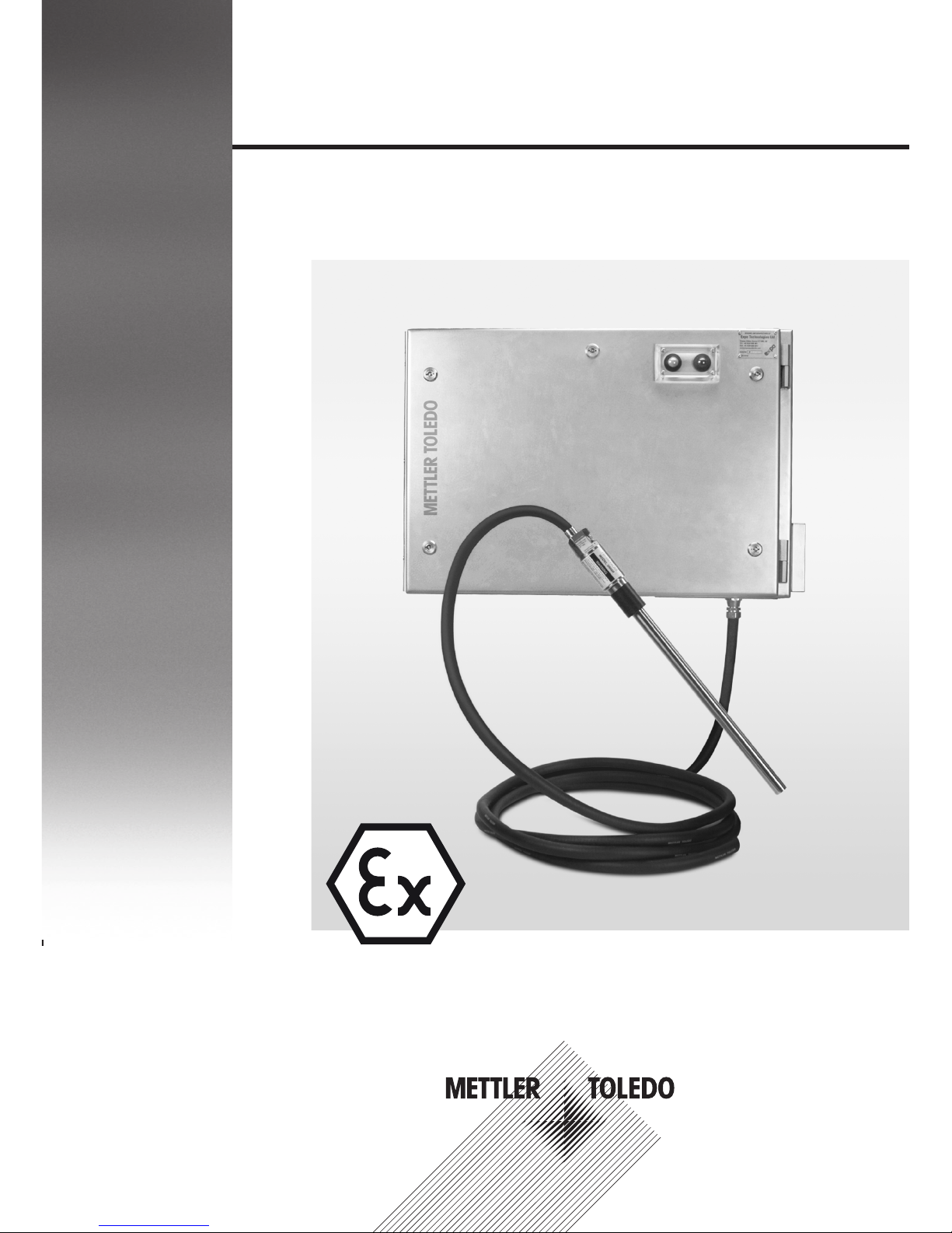
ParticleTrack G600Ex
Real-Time Particle Characterization
Hardware Manual
Page 2

2
Hardware Manual
No part of this publication may be stored in a
retrieval system, transmitted, or reproduced in
any way, including but not limited to photocopy,
photograph, magnetic or other record, without
the prior written permission of Mettler-Toledo
AutoChem, Inc.
FBRM®, iC Process™, iC FBRM™, PVM™, and
iCPVM™ are trademarks of Mettler-Toledo
AutoChem, Inc.
Microsoft® and Windows® are either registered
trademarks or trademarks of Microsoft Corporation
in the United States and/or other countries.
All other brand and product names are trademarks
or registered trademarks of their respective owners.
The information in this publication is provided for
reference only. All information contained in this
publication is believed to be correct and complete.
Mettler-Toledo AutoChem, Inc. shall not be liable
for errors contained herein nor for incidental or
consequential damages in connection with the
furnishing, performance, or use of this material. All
product specifications, as well as the information
contained in this publication, are subject to change
without notice.
For technical support, email: AutoChemCustomerCare@mt.com
For updates, webinars, and the latest documents: https://community.autochem.mt.com
Mettler-Toledo AutoChem, Inc.
7075 Samuel Morse Drive
Columbia, MD 21046
www.mt.com/AutoChem
Tel: + 1 866.333.6822
Fax: +1 410.910.8600
This publication may contain or reference
information and products protected by copyrights
or patents and do not convey any license under
the patent rights of Mettler-Toledo AutoChem, Inc.,
nor the rights of others. Mettler-Toledo AutoChem,
Inc. does not assume any liability arising out of
any infringements of patents or other rights of third
parties.
Mettler-Toledo AutoChem, Inc. makes no warranty
of any kind with regard to this manual, including
but not limited to the implied warranties of
merchantability and fitness for a particular purpose.
1115 2 01 6
Page 3

3
1 Introduction
This manual covers specific safety and quality information relating to the
ParticleTrack™G600Ex with FBRM® (Focused Beam Reflectance Measurement)
technology. Throughout this manual, the system is referred to by the name:
ParticleTrack G600Ex or FBRM G600Ex. The ParticleTrack G600Ex system includes the
base unit with purge and pressurization system and a probe connected by a flexible
armored conduit. The purge and pressurization system for the base unit enclosure
enables use of the ParticleTrack G600Ex system in potentially explosive atmospheres in
an above-ground (Group II) application.
www.mt.com/ParticleTrack G600Ex
Contents
1 Introduction
2 Intended Use
3 Technical Data
4 Safety Information
5 Supplementary Documentation
6 Product Installation
7 Flexible Probe Mounting Options
8 Operating Instructions
9 Best Practices for Routine Operation
10 Troubleshooting
11 Product Maintenance
12 Disposal
Page 4
4
Hardware Manual
2 Intended Use
The METTLER TOLEDO AutoChem ParticleTrack G600Ex is an analyzer that provides
in-process real-time particle characterization. The apparatus is comprised of an Expo
Technologies Ltd PE2E stainless steel enclosure with dimensions of approximately 500
x 750 x 250 mm, complete with integral MiniPurge type px purge and pressurization
system, associated MiniPurge Interface Unit, and maintenance override switch. Refer to
the EXPO MiniPurge and Enclosure manual (ML482) for more information.
The installed electrical apparatus is comprised of a power supply; laser and detector
modules, laser current limiter assembly, fiber optic communications, PCBs, and
pneumatic controls. The apparatus is fitted with a permanently attached flexible armored
conduit, which is connected to the process probe.
The pressurized enclosure may be used in Zone 1 or Zone 21 hazardous areas, and
the probe may be used to monitor a process in Zone 0 or Zone 20 hazardous areas.
The flexible conduit connecting the probe to the main enclosure shall not be installed in
Zone0 / Zone 20.
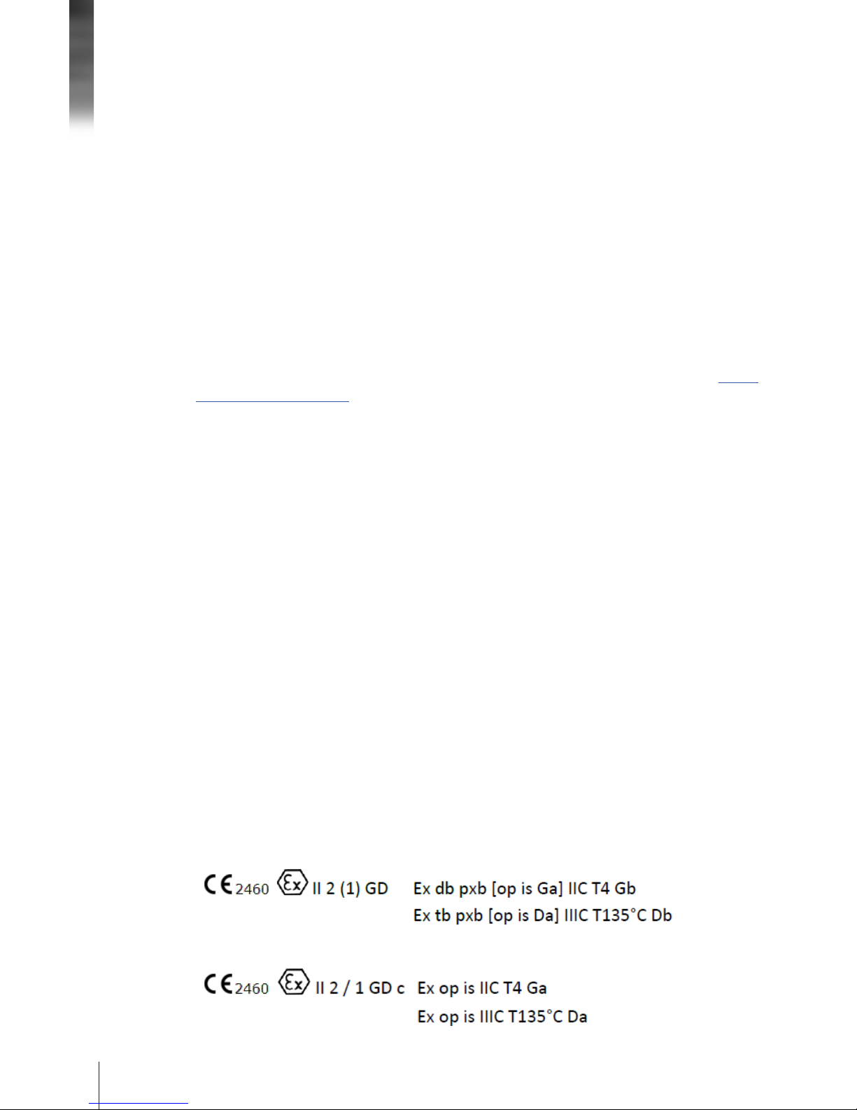
The analyzer and probes have been analyzed according to the ATEX directive and are
marked as follows:
Analyzer:
Probe:
The purge and pressurization system controls the flow of instrument air (or inert gas)
into the base unit enclosure and maintains a constant pressure that is slightly higher
than the ambient pressure outside the enclosure. The overpressure in the enclosure
ensures gas from outside the enclosure cannot enter the base unit. If the pressure is
lost for any reason, the power to the base unit shuts down automatically. The purge
and pressurization system operates pneumatically and requires no electrical supply to
function.
ParticleTrack G600Ex with FBRM technology is a rugged probe-based instrument that
is inserted directly into large-scale vessels or pipelines to track changing particle size
and count in real time at full process concentrations. Particles, particle structures, and
droplets are monitored continuously, as process parameters vary, enabling engineers to
effectively troubleshoot and improve processes effectively. Click the link to see the FBRM
Method of Measurement video (requires internet connection).
Page 5
5
Purge gas Instrument air
Purge ow rate 225 L/min
Minimum overpressure 0.5 mbarg
Maximum overpressure 12 mbarg
Minimum purging time 5 minutes
Air supply pressure 4 to 8 barg
Maximum leakage rate
30 L/min
Purge Parameters
Table 1. Purge parameters
System certications
Class I/Division 1 Group A-D, T4
ATEX and IECEx
Analyzer (Enclosure): CE
2460
Ex II 2 (1) GD Ex db pxb [op is Ga] IIC T4 Gb
Ex tb pxb [op is Da] IIIC 135°C Db
Probe: CE
2460
Ex II 2/1 GD c Ex op is IIC T4 Ga
Ex op is IIIC T135°C Da
Laser classication Class 1 Laser Device, Compliant with 21 CFR 1040.10 and
1040.11 and IEC 60825-1
Ingress protection IP66
Functional specications
Method of Measurement Focused Beam Reectance Measurement (FBRM®)
Measurement range 0.5 to 2,000 µm
Scan speed 2 m/s (standard); 4 m/s (optional)
3 Technical Data
Table 2. System certications and functional specications
Page 6
6
Hardware Manual
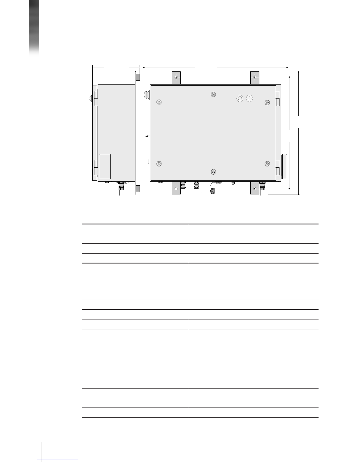
450 mm
[
17.7”
]
660 mm
[
26.0”
]
809 mm
[
31.9”
]
600 mm
[
23.6”
]
284 mm
[
11.2”
]
Figure 1. Base unit enclosure dimensions
Environmental
Operating humidity range 0 to 85%
Operating temperature range 0 to 40 °C
Installation
Earth/Ground strap (customer-provided) Minimum 3.31 mm2 [12 AWG]
to 6.35 mm stud on enclosure
External connection Hawke type ICG 635 or equivalent
General
Material of construction SS316
Ingress protection IP 66 (4X equivalent)
Power Ratings Voltage: 100–125 V or 200–240 V
Frequency: 50/60 Hz
Max Current: 0.5 A
Max Power Consumption: 60 W
Fuses Main power fuse: 2.0 A, 250 V Slow Blow, Type T
Laser fuse: 0.15 A, 205 V, T-LAG
Weight 54.4 kg [120 lb]
Communication interface Fiber Option to USB 2.0
Installation (overvoltage) category II
Base Unit Specifications
Table 3. Base unit specications
Page 7
7
419 mm
[
16.5”
]
368 mm
[
14.5”
]
206 mm
[
8.1”
]
500 mm
[
19.7”
]
546 mm
[
21.5”
]
25 mm
[
Ø 0.98”
]
42 mm
[
Ø 1.66”
]
50 mm
[
Ø 1.95”
]
400 mm
[
15.75”
]
182 mm
[
7.18”
]
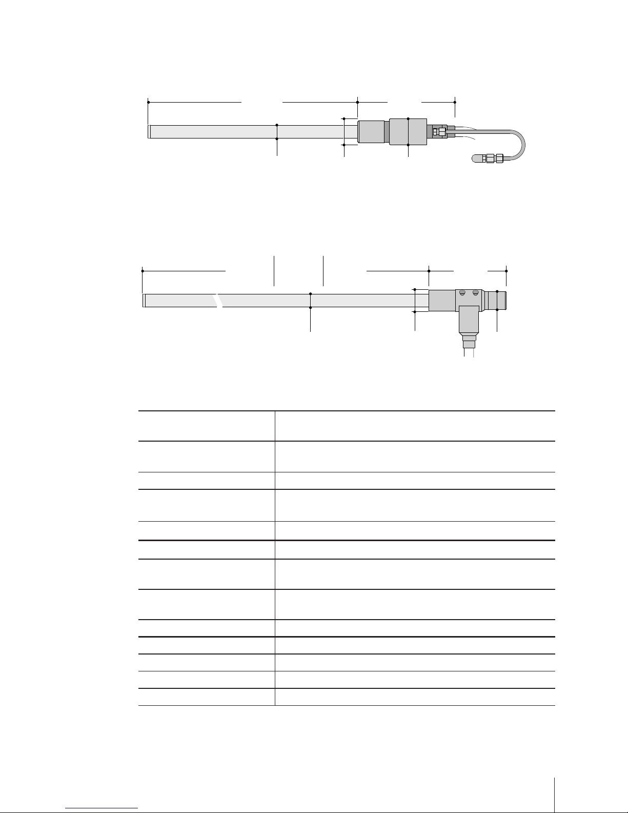
Figure 2. Probe dimensions—G600R
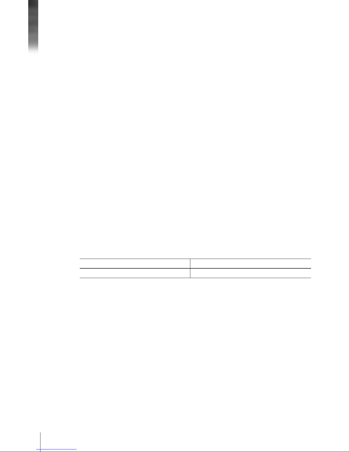
Figure 3. Probe dimensions—G600T, P, X
419 mm
[
16.5”
]
368 mm
[
14.5”
]
206 mm
[
8.1”
]
500 mm
[
19.7”
]
546 mm
[
21.5”
]
25 mm
[
Ø 0.98”
]
35 mm
[
Ø 1.38”
]
42 mm
[
Ø 1.66”
]
148 mm
[
5.82”
]
T
400 mm
[
15.75”
]
P
1000 mm
[
39.40”
]
X
Custom
Length
25 mm
[
Ø 0.98”
]
42 mm
[
Ø 1.66”
]
50 mm
[
Ø 1.95”
]
400 mm
[
15.75”
]
182 mm
[
7.18”
]
Wetted materials of
construction
Probe tip SS316L (standard)
Alloy C22 (optional)
Probe window Sapphire
Probe window seals Kalrez® 6375 (standard)
TM [Thermo-Mechanical press-t] (optional)
Environmental
Operating pressure range 0 to 10 barg (standard)
Up to 250 barg (optional, requires custom engineering design)
Operating temperature range -10 to 120 °C (Kalrez® 6375 window seal)
-80 to 120 °C (TM window seal)
Installation
Conduit length 15 m [49.2 ft]
Conduit bend radius (min.) 20 cm [8 in]
Probe and conduit weight 6.8 kg [15 lb]
Table 4. Probe specications
Probe Specifications
Page 8
8
Hardware Manual
Site preparation for the METTLER TOLEDO ParticleTrack G600Ex system is the end user's
responsibility. The following should be considered to ensure successful installation of the
system:
Power Requirements
A temporary power cord is provided with the ParticleTrack G600Ex system for
convenience of installation and commissioning. The final installation must comply
with EN60079-14 and use fittings and wiring rated appropriately for the location. The
equipment shall be permanently installed to the main power supply through metal conduit
with > 75 °C temperature-rated cable and connected to protective earthing. A 10-ampere
circuit breaker should be included in the building installation to provide overcurrent
protection. The circuit breaker should be within easy reach of the operator and marked as
the disconnecting device for the connection.
Air/Gas Requirements
A ParticleTrack G600Ex system requires a source of clean, dry, and pressure-regulated
instrument air or inert gas to drive the probe optical scanner. The quality of the air or
gas supply must meet the specifications of the American National Standards Institute/
Instrument Society of America (ANSI/ISA) S7.0.01-1996 Quality Standard for Instrument
Air. Air/gas must:
• Have a dew point at least 10 °C [50 °F] lower than the minimum temperature to
which any part of the system will be exposed.
• Contain less than 1 ppm total oil or hydrocarbons
• Contain less than 1 ppm particulates at a maximum size of 3microns
• Be free of any corrosive contaminants and flammable or toxic gases.
Air supply pressure 4.5 to 5.2 barg [65–75 psig]
Maximum ow rate 40 L/min [1.4 SCFM]
Table 5. Probe air/gas specication
Area of Intended Use
Ensure the area of intended use has adequate space to mount the base unit and a
support structure capable of supporting the system weight. The base unit has mounting
tabs for four (4) 8 mm [5/16 inch] minimum diameter stainless steel bolts (end user-
provided). The support structure must not be subject to excessive vibration. The probe
conduit should not bend beyond 20 centimeters (8 inches) and it should not be put
into an “S” shape. Include a suitable work location for the control computer that allows
connectivity through a USB cable.
The base unit must be convenient for access (eye level) and readily accessible for
service. It can also operate in a horizontal position—placed back side down on a
flat horizontal surface. Position the base unit to enable easy access to the purge and
pressurization system air supply. The ParticleTrack G600Ex base unit contains sensitive
electronic components that should be protected from severe environmental conditions.
If the area is outdoors in warmer climates, the base unit must be shaded from direct
sunlight.
Page 9

9
The CE Mark applies only to unmodied instruments as supplied by MettlerToledo AutoChem, Inc. Modications may require on-site testing for compliance
verication. If the equipment is used in a manner not specied by the manufac-
turer, the protection provided by the equipment may be impaired.
Caution—Read all safety warnings before installing or operating this equipment. Failure to follow the instructions and caution/warning statements could
result in personal injury and/or product damage that could void the warranty.
WARNING—Main power shall be supplied through a metal conduit following
local and governmental regulations.
WARNING—Only skilled, trained technicians can service this equipment.
WARNING—Pressurized Enclosure. Do Not Open When Flammable Gas Is
Present Even When De-Energized.
WARNING—Do Not Open When An Explosive Atmosphere Is Present
WARNING—Power shall not be restored after the enclosure has been opened
until combustible dust accumulations within the enclosure have been removed.
Table 6. Safety cautions and warnings
4 Safety Information
Special Conditions of Safe Use
1. The user shall ensure that the exit of air from the purge cannot disturb surrounding
dust deposits and hence create a dust cloud.
2. Cable glands used for connection to the flameproof terminal compartment shall
be Ex-certified flameproof type, certified as apparatus and employ sealing around
individual cores. Additional thread adapters shall not be used.
3. The optical cable connecting between the purge enclosure and the USB-to-Fiber
converter must be protected from damage that could allow the release of optical
energy. This may be accomplished by either using armored type optical cable, or by
routing the cable via rigid conduit.
4. The protective non-metallic cover of the purge indicators presents a potential
electrostatic charging hazard. Do not rub with a dry cloth or clean with solvents.
Clean only with a water damp cloth.
Page 10

10
Hardware Manual
Laser Classification
All standard-model FBRM G600 Ex instruments are in compliance with the U. S.
Department of Health and Human Services (DHHS) Radiation Performance and in
accordance with International Standards.
THE FBRM G600 Ex IS A CLASS 1 LASER PRODUCT COMPLIANT WITH
DHHS 21 CFR 1040.10 AND 1040.11
EXCEPT FOR DEVIATIONS PURSUANT TO LASER NOTICE 50, DATED JUNE 24, 2007.
THE FBRM G600 Ex IS A CLASS 1 LASER PRODUCT COMPLIANT WITH IEC 60825-1
Laser de Classe 1
Conforme à la norme 21 CFR 1040.10 et 1040.11
À l'exception des écarts conformement à l'avis Laser 50 en date du 24 Juin 2004,
et conforme à la norme IEC 60825-1
LASER SAFETY WARNING
Opening the enclosure and making adjustments, or performing procedures
other than those specied in the instrument manual may result in hazardous
radiation exposure.
Caution—Use of controls or adjustments or performance of procedures other
than those specied in the instrument manual may result in hazardous
radiation exposure.
There are no user-serviceable components in the laser module. Only skilled,
trained technicians can service this equipment.
Looking directly into the aperture of any laser-emitting device is never advised.
Table 7. Laser safety warnings and cautions
5 Supplementary Documentation
An electronic ParticleTrack G600Ex Hardware Documentation Portfolio, shipped with the
instrument, includes the following documents in addition to this manual:
• QuickRef: “Positioning the ParticleTrack or ParticleView Probe” (MK-PB-0050-AC)
• “Calibration Validation in iC FBRM” (MK-PB-0071-AC)
• “System Calibration in iC FBRM” (MK-PB-0082-AC)
• “Calibration Validation in iC Process for FBRM” (MK-PB-0109-AC)
• “System Calibration in iC Process for FBRM” (MK-PB-0110-AC)
Please refer to the iC FBRM and iC Process for FBRM software user assistance and
Documentation Portfolios for software publications.
Check the https://community.autochem.mt.com site for the latest portfolios.
Page 11

11
6 Product Installation
ParticleTrack G600Ex system installation involves three connections to the power, air,
and communication inlets at the bottom of the base unit. A qualified METTLER TOLEDO
Field Service Engineer performs a ParticleTrack G600Ex system installation. After initial
installation, if the system requires relocation or installation after depot repair, use the
steps outlined below. METTLER TOLEDO is available to provide the service if necessary.
Connect Power (A)
Ensure that your power supply meets the electrical specifications in section 3 "Technical
Data" on page 5.
1. Run power, using fittings and wiring rated appropriately for the location, from the
main supply to the terminal block inside the purge and pressurization system;
interface through the base of the enclosure (A in Figure 4 and Figure 5). The purge
and pressurization system bypass, located inside the enclosure, must be hard-wired
for 115 V or 230 V, as applicable.
2. Use ground strap (customer-provided) with minimum 3.31 mm2 [12 AWG] and
connect to the earth/ground stud on right side of enclosure
3. If necessary, provide an AC Line Conditioner for noisy power.
US B
Figure 4. Instrument connections: (A) Power; (B1) Air inlet for enclosure purge and
pressurization; (B2) Air inlet for probe scanner; (C) Fiber communication connection;
(D) Fiber-to-USB extender; (E) USB cable; (F) Extender power supply
E
C
F
D
B1
B2
A
Page 12

12
Hardware Manual
Figure 5. Wiring: Power to
purge and pressurization
interface unit
Wire * Coil (ABB) Terminals
100–125 V
Green/Yellow GND (Ground from power cable)
Brown 1L1 (Line from power cable) 115 (Jumper from 1L1)
Blue 3L2 (Neutral from power cable) N (Jumper from 3L2)
200–240 V
Green/Yellow GND (Ground from power cable)
Brown 1L1 (Line from power cable) 230 (Jumper from 1L1)
Blue 3L2 (Neutral from power cable) N (Jumper from 3L2)
* NOTE: Wire color may vary depending on the global location.
Table 8. Permanent power cord wiring
NOTE: Figure 5 shows a typical layout for wiring. The orientation of the bypass block can
vary. Please wire to the empty 115 V and 230 V locations per Table 8 below.
A
3L2
N
230
115
GND
1L1
Page 13

13
Connect Air Supply (B1 and B2)
A ParticleTrack G600Ex system requires instrument quality air connections for the
enclosure purge/pressurization system and for the pneumatically driven probe scanner.
Air Supply to Purge and Pressurization System
The purge and pressurization system comes standard with an air regulator/filter
assembly. The required 1/2" tubing is rated for 8 barg [120 psig] air service and flame
retardant. Tubing may be made of polypropylene, PVC, or nylon.
1. Clean/purge all air lines and tubes before connection to the ParticleTrack G600Ex
instrument.
2. Connect air for the purge and pressurization system via the air regulator/filter
assembly provided to the air inlet (B1 in Figure 4) identified at the bottom of the
enclosure.
Air Supply to Probe Scanner
A ParticleTrack G600Ex system requires instrument quality air for the pneumatically
driven probe scanner and comes standard with an air regulator. The regulator/filter
assembly has two filters, a general purpose filter and a coalescing filter, that can be
replaced if they become dirty. The required tubing is 1/4" OD, rated for 8 barg [120 psig]
air service and flame retardant. Tubing may be made of polypropylene, PVC, or nylon.
1. Install air regulator and filter within six feet (two meters) of the enclosure.
2. Clean/purge all air lines and tubes before connecting to the ParticleTrack G600Ex.
3. Connect the tubing between the air supply, the regulator, and the scanner air inlet
(B2 in Figure 4) at the bottom of the ParticleTrack G600Ex base unit.
NOTE: Air flows in the direction indicated by the arrow on the front of the coalescing
filter.
4. Ensure the bowl assembly on the general purpose filter is fully inserted and locked in
place by rotating it to the right.
Page 14

14
Hardware Manual
Connect Fiber-to-USB Communications (C, D, E, F)
The ParticleTrack G600Ex connects to the computer by a custom fiber optic cable with an
industrial LC-type connector via a Fiber-to-USB Extender (D). Both the fiber optic cable
and the extender are supplied with the system. Follow the steps below.
1. Locate the fiber optic input at the bottom of the ParticleTrack G600Ex base unit and
connect one end of the supplied fiber optic cable to the input (C).
2. Plug the other end of the fiber optic cable to the fiber optic input on the Fiber-to-USB
extender (D).
3. Connect the USB cable (E) from the Host input of the extender to a USB port on the
control computer.
4. Connect the power supply (F) to the USB extender and an AC outlet.
Install Probe
A variety of probe mounting options are available using the METTLER TOLEDO Flexible
Mounting System ("Flexible Probe Mounting Options" on page 16). Due to the complex
nature of multi-phase flow, proper installation is very important for successful application
of inline particle and droplet measurement techniques. Installation and mounting of
probe-based instruments for particle characterization should consider multiple factors
including:
• Existing or planned process equipment
• Scale and control capabilities of existing installation ports
Page 15

15
B CA
D
Figure 6. Implementation of a ParticleTrack instrument: (A) ush with wall of vessel or pipeline; (B) inserted
tangentially to process ow; (C) inserted perpendicular to process ow at an elbow; and (D) inserted at
optimal angle (45°) relative to process ow.
• Expected ranges of process variables such as temperature, pressure, flow
rates, and/or flow patterns
• Expected range of particle/droplet size and concentration
• Probe location and orientation (Figure 6)
Page 16

16
Hardware Manual
7 Flexible Probe Mounting Options
The Flexible Mounting System enables the attachment of both industry standard and
custom designed flange adapters and fittings without permanent modification of the
probe. Length reducers are an option for use with flange adapters and other flexible
mounting kits to provide a practical means of decreasing the probe wetted length when a
shorter insertion depth is required. The innovative design from METTLER TOLEDO allows
probes with this flexible mounting adapter to be easily moved from one installation point
to another at a lower overall cost. Figure 7 shows some of the standard options available
for mounting to the Flexible Mounting Adapter (A).
Figure 7.
ParticleTrack G600Ex
exible mounting options
1 2 3 4
A
Page 17

17
In addition to the standard Flexible Mounting System options, METTLER TOLEDO can
provide custom and special-order probe designs. Custom probes can be manufactured
with permanently welded flange adapters and fittings to meet specific installation
requirements that are not possible with the existing Flexible Mounting System. All
custom and special order installation requirements should be discussed with your
METTLER TOLEDO Technology and Applications Consultant, and may involve custom
engineering and design charges.
G600T
G600P
G600R
1
Flange Adapter Kits
For installation of probe through industry standard (ANSI) flanged
ports.
• • •
2
Tri-Clamp® Adapter Kits
For installation using industry standard Tri-Clamp® flanges.
• • •
3
Dip Pipe Installation Kits
For simplified installation in large vessels using a custom dip pipe.
Dip Pipe Adapters allow probes to be installed inside dip pipes of
customized lengths to extend the effective length of the probe up to 5
meters. A Dip Pipe Installation requires the purchase of two separate
accessories including (1) a Dip Pipe Installation Kit and (2) a Dip
Pipe Adapter that is welded to a standard pipe during the construction
of the dip pipe. The dip pipe is supplied by the customer.
•
4
Ball Valve Assembly
For installation into an active pipeline, the FBRM Ball Valve Assembly
is designed to allow the insertion or removal of a probe into a flowing
stream without requiring shut down of the process. Using a ball valve
assembly also helps avoid spills to minimize exposure of personnel
and environment to the contents of the process stream.
• •
Table 9. Flexible mounting options
Page 18

18
Hardware Manual
8 Operating Instructions
During system installation, a trained METTLER TOLEDO engineer makes all system
connections and verifies the system is ready for use.
1. Verify the base unit door is securely locked. Use the supplied key to lock the six
latches on the enclosure door.
2. Start inlet air supply to the Probe Scanner and regulate flow to:
4.5–5.2 barg [65–75 psig].
3. Start up the purge and pressurization system.
a. Apply inlet air supply to purge and pressurization system and regulate flow
at 4.8barg [70 psig]. The acceptable regulated pressure range is 4–8barg
[60–120 psig].
b. The purge system starts automatically and the purge indicators (Table 10) on the
enclosure cover change color. Before air is applied, the indicators are Red-Black.
After air is applied, the indicators change to Green-Yellow (Purging), followed by
Green-Black when the enclosure is purged/pressurized.
c. Purge for a minimum of 5 minutes at a minimum purge flow rate of 225 L/min.
d. Observe purge indicators change to Green-Black when the enclosure is purged
and pressurized.
e. After the purge completes, the purge and pressurization system interface unit
automatically applies power to the ParticleTrack G600Ex system.
Unpressurized / Alarm Condition
"Purging"
The process takes approximately ve (5) minutes.
"Pressurized"
Purge complete.
Table 10. Purge and pressurization system indicators
Page 19

19
Indicators LED State Status
Host ON (Solid Green) USB cable between PC and HOST is properly connected
Power ON (Solid Green) Power supply is properly connected to extender
Link
ON (Solid Green) Powered, HOST is identified, and Fiber is properly
connected
LOS
ON (Solid Red) Loss of Signal—No communication between
instrument and PC
Table 11. USB Extender LEDs
NOTES:
- If the right indicator remains yellow or changes to yellow during operation, the
purge air flow is inadequate. Check the air supply and connections.
- Venting of the relief valve during operation is considered normal. The airtight
enclosure relies on the use of the relief valve to ensure a consistent level of
pressurization is maintained within the enclosure.
- Ensure the ParticleTrack G600Ex system has been powered ON for 30 minutes
before performing calibration validation or recording process measurements.
4. Observe LED indicators on USB Extender.
5. Turn on control computer and start the software. To add/configure the
instrument in iC FBRM or iC Process for FBRM, please refer to the applicable online
User Assistance.
Page 20

20
Hardware Manual
9 Best Practices for Routine Operation
Ensure Reliable Instrument Performance
• Follow recommended calibration validation procedures monthly or quarterly as
determined by your SOP.
• Follow preventative maintenance guidelines for your ParticleTrack instrument.
• Check probe window cleanliness as part of routine SOP.
Ensure Measurement Sensitivity by Optimizing Probe Location and Positioning
• Probe should be positioned in the process where it can obtain maximum sensitivity to
changes in particle or droplet system.
• Probe must be oriented to ensure particle system flows optimally across the probe
window surface.
• Probe tip must remain fully immersed to provide measurements of the particle/droplet
system.
• Probe location is more critical under the following conditions:
- Extreme difference between particle density compared to the carrying solution
density (ranges from very low or very high)
- Lower Rheology
- Larger median particle dimension
- Greater deviation between average particle shape and a sphere (more irregular
particles or particle structures)
• Probe location is less critical under the following conditions:
- Smaller difference between particle density compared to carrying solution density
- Higher solids concentration (or higher dispersed phase in liquids)
- Smaller median particle dimension
- Narrower particle distribution
- Smaller deviation between average particle shape and a sphere (fewer irregular
particles or particle structures)
Page 21

21
Track Particle Systems Reliably
• Use iC FBRM for routine monitoring of particle and droplet systems in the laboratory.
Use iC Process for FBRM for secure and reliable monitoring of particle and droplet
systems in batch or continuous processes.
• Use iC FBRM for advanced data analysis of data collected in either iC FBRM or iC
Process for FBRM.
• Use iC FBRM for further improvement and optimization of Process Methods to be used
in SOPs.
Develop a Standard Operating Procedure (SOP)
• Select or create an appropriate iC FBRM template for each given application. A welldesigned template will simplify the startup procedure and ensure consistent operation
in each experiment.
• Include appropriate statistical trends that can directly track particle and product and
quality parameters of interest.
• Include reference and target distributions as process milestones or final product
quality set-points.
• Optimize the measurement configuration (measurement interval and averaging
settings) to ensure robust repeatable measurement and to maximize sensitivity to
dynamic changes in the particle system.
Save Experiment Settings as a Template—Make sure to develop the right template for
a specific particle or droplet system. Save a template that includes trends and reference
distributions that are important to track to characterize the particle or droplet system.
Manage Reference Distributions—Distributions can be saved as references and
designated as targets for subsequent experiments. Reference distributions or target
distributions can be saved in particle-specific templates.
Check Probe Window Cleanliness—The probe window must be clean before mounting
in particle or droplet system and before performing Calibration Validation.
Page 22

22
Hardware Manual
Warnings
Table 13. Troubleshooting warnings
Warning Message Description Possible Cause
Effective Duration
Low
Effective Duration is a
measure of the data
transfer efficiency. Normal
operation results in an
Effective Duration of
approximately 50%.
Effective Duration Low may indicate that
PC specifications are inadequate. A low
Effective Duration may reduce the
precision of the measurement.
If the Effective Duration is significantly less
than 40%, contact METTLER TOLEDO.
The measurement interval can also impact
Effective Duration. Only select an interval
<10 s where you expect rapid process
changes.
Average Signal
Intensity High
Average Signal Intensity is
an indicator of the amount
of light backscattered by
the particles or droplets
being measured.
Average Signal Intensity High may indicate
that the particles being measured are
highly reflective. Very high backscatter
may saturate the sensor, resulting in
erroneous measurements.
Table 12. Troubleshooting errors
Error Message Description Possible Cause
Air Filter Pressure
High / Low
Pressure measured at the
outlet of the internal air
filter is outside the
recommended range
Possible causes include scanner inlet
pressure is not set within recommended
range or filter is clogged and needs
replacement.
Box Temperature
High / Low
Internal temperature of
base unit has fallen
outside of the
recommended operating
temperature range.
The base unit is installed in a location that
is not within recommended specification.
Scan Speed or
Scan Frequency
High / Low
Desired scan speed or
frequency is outside
acceptable range.
Air pressure to probe scanner is set
incorrectly. Check the pressure and
regulate to proper range. If error continues,
contact METTLER TOLEDO.
Tach Pulse
Missing
Data acquisition error. Verify USB and fiber connections are
secure. If error continues, contact
METTLER TOLEDO.
10 Troubleshooting
Errors are generally hardware-related issues that affect data acquisition. The
following table documents how hardware errors are displayed in the control software,
describes what the error means and provides possible root causes to assist with
troubleshooting and resolving the issue. If the issue cannot be resolved, please contact
AutoChemCustomerCare@mt.com for assistance.
Errors
Page 23

23
11 Product Maintenance
METTLER TOLEDO warrants its products against defects in materials and workmanship for
twelve months from the date of installation or fifteen months from the date of shipment,
whichever comes first. For details, please refer to the warranty provided with the
instrument. For assistance, please email AutoChemCustomerCare@mt.com.
It is recommended that you retain the original packing materials if you need to return
the ParticleTrack system. If factory service is required, your METTLER TOLEDO service
engineer will issue you a Return Material Authorization (RMA) form.
There are no user-serviceable parts inside a ParticleTrack G600Ex. Contact your
METTLER TOLEDO Field Service Engineer for all service needs. Unauthorized service may
damage the instrument.
Schedule the routine maintenance tasks outlined below. To facilitate maintenance (with
the ParticleTrack G600Ex door open) when the purge and pressurization system cannot
be used, a key is provided. The key operates the Bypass switch (A in Figure 8). System
must be in a safe location.
When the enclosure is opened for service, observe the warning inside the enclosure (and
shown in Table 6 on page 9 under "Safety Information").
• Ensure the air/gas supply meets the required standards.
• Replace the ParticleTrack G600Ex air filter if it becomes dirty. Since instrument quality
air should not result in a dirty filter, look for and correct the problem that is causing
the air contamination.
• Run the Calibration Validation procedure for the probe every three to six months, if
the probe is dropped or relocated, and after new software is installed, if desired. If the
Calibration Validation does not pass, follow the System Calibration procedure.
• The ParticleTrack G600Ex system is designed for indoor or outdoor use. The base unit
can be sprayed with water jets to clean in plant environments and the system is easily
cleanable with a water-damp cloth. Use caution when cleaning exhaust on probe. The
protective non-metallic cover of the purge indicators presents a potential electrostatic
charging hazard. Do not rub with a dry cloth or clean with solvents. Clean only with a
water-damp cloth.
• Periodically perform the following maintenance task to verify purge and pressurization
system function.
a. With the enclosure closed, turn on
the purge and pressurization air and
adjust the pressure gauge to 4.8 barg
[70 psig].
b. Verify the Purge Cycle time is at least
five (5) minutes.
c. Verify the purge cuts power to the
system when door is opened.
d. Close door.
Figure 8. Bypass switch
A
Page 24

24
Hardware Manual
Relocation, Shipment, or Storage
To prevent and minimize damage to the ParticleTrack G600Ex, follow the instructions
below to prepare the system for relocation, shipment, or storage.
1. Close the iC FBRM or iC Process for FBRM software application and shutdown the
computer according to normal operating procedures.
2. Disconnect the power, air, and communications from the bottom panel of the base
unit enclosure.
3. Disconnect the Fiber-to-USB Extender from the power supply and from the control
com puter.
4. Store the system and all components in the factory-supplied crate.
Replacement Interval Part
Annually PVC Reference Sample, G600
• customer-replaceable
• PVC life: 10 uses or one year, whichever comes rst
• included in annual PM
Internal Filter Assembly
External Air Regulator, Filter (customer-replaceable)
Every two (2) years Control Valve
Every three (3) years Laser Board
Table 14. Parts life expectancy
METTLER TOLEDO has offices around the world. Contact the Mettler-Toledo AutoChem,
Inc., headquarters in the USA for technical support or service. To arrange for specific
application assistance from a METTLER TOLEDO Technology and Applications Consultant,
or for assistance, contact Customer Care through the toll-free number on page 2.
Recommended Maintenance
A qualified METTLER TOLEDO Field Service Engineer should perform regular Preventive
Maintenance (PM) on the system. Table 14 shows the normal life expectancy of several
components and identifies any customer-replaceable parts. Use this information for
planning potential cost of ownership.
Page 25

25
12 Disposal
Please dispose of this product in accordance with local regulations at the collecting point
specified for electrical and electronic equipment.
If you have any questions please contact the responsible authority or the distributor from
which you purchased this device.
Thank you for your contribution to environmental protection.
Notes
Page 26

Mettler-Toledo AutoChem, Inc.
7075 Samuel Morse Drive
Columbia, MD 21046 USA
Telephone +1 410 910 8500
Fax +1 410 910 8600
Email autochem@mt.com
Internet www.mt.com/autochem
Subject to technical changes
© 11/2016 Mettler-Toledo AutoChem, Inc.
Printed in USA MK-PB-0079-AC Rev E DCN 3000
Visit for more information
www.mt.com/ParticleTrack
Our on-demand webinars (online seminars) provide application
and industry information relevant to you. These interactive
presentations, provided by industry experts and our own
applications team, give you an opportunity to learn more about
your specific area of interest.
Topics include:
• Improving Crystallization and Precipitation Processes
• The Importance of Mixing in Process Development
• Avoiding Incidents During Scale-up
• Recent Advances in Organic Chemistry
• Calorimetry Best Practices
• Characterization of Catalytic Hydrogenations
• Plus other applications including green chemistry, organic
synthesis, fermentation, high pressure chemistry and more
www.mt.com/ac-webinars
Learn More with our
Technical Webinar Program
 Loading...