

Mettler Toledo Profibus-Module, DeviceNet-Module, EtherNet/IP-Module, ProfiNet IO-Module, CC-Link Module Operating Instructions Manual
Page 1

Modules
Fieldbus
Operating Instructions
Page 2

Leer
Page 3

Table of Content
1 Introduction...........................................................................................................................................6
1.1 General ..................................................................................................................................................6
1.2 Compatibility .......................................................................................................................................... 7
1.3 Related documentation ............................................................................................................................ 7
1.4 Internet addresses ................................................................................................................................... 7
2 Functional Overview .............................................................................................................................8
2.1 Data exchange model..............................................................................................................................8
3 Set-up Checklist .................................................................................................................................... 9
4 Step-by-Step Installation and Configuration .......................................................................................... 10
4.1 Configure the weighing sensor ................................................................................................................10
4.1.1 Adjustment of interface communication parameters of the weigh modules ...................................................10
4.1.2 Adjustment of interface communication parameters of other weighing sensors .............................................10
4.2 DIN-Rail mounting ................................................................................................................................11
4.3 Connect the Fieldbus-Module to a PC for initial configuration ......................................................................11
4.4 Connect the Fieldbus-Module to the weighing sensor .................................................................................12
4.4.1 WMS, WM and WMH weighing sensor .................................................................................................... 12
4.4.2 Other METTLER TOLEDO balances and weighing sensors ...........................................................................13
4.5 Connect the Fieldbus-Module to a power supply ....................................................................................... 13
4.6 Configure the Fieldbus-Module................................................................................................................14
4.6.1 PC terminal software ............................................................................................................................. 14
4.6.2 Weighing sensor interface ...................................................................................................................... 15
4.6.3 Baudrate .............................................................................................................................................. 15
4.6.4 Character format ................................................................................................................................... 15
4.6.5 Operation mode .................................................................................................................................... 15
4.6.6 Maximum response time........................................................................................................................15
4.6.7 Configuration from network ....................................................................................................................15
4.6.8 Automatic baudrate search .....................................................................................................................16
4.6.9 Save configuration to flash ..................................................................................................................... 16
5 Fieldbus-Modules ................................................................................................................................ 17
5.1 Profibus-Module ...................................................................................................................................17
5.1.1 General ................................................................................................................................................17
5.1.2 Supported features ................................................................................................................................17
5.1.3 Identification numbers ...........................................................................................................................17
5.1.4 Profibus node address ..........................................................................................................................17
5.1.5 Cabling ................................................................................................................................................18
5.1.6 Bus termination ...................................................................................................................................18
5.1.7 GSD configuration file ............................................................................................................................ 18
5.1.8 Configure and start the Profibus network .................................................................................................. 18
5.1.9 LED indication table .............................................................................................................................19
5.2 DeviceNet-Module ................................................................................................................................. 20
5.2.1 General ................................................................................................................................................20
5.2.2 Supported features ................................................................................................................................20
5.2.3 Identification numbers ...........................................................................................................................20
5.2.4 Network configuration ............................................................................................................................21
5.2.4.1 Mac address ........................................................................................................................................21
5.2.4.2 Baudrate .............................................................................................................................................. 21
5.2.5 Cabling ................................................................................................................................................21
5.2.6 EDS configuration file ............................................................................................................................21
5.2.7 Configure and start the DeviceNet network................................................................................................22
5.2.8 LED indication table ..............................................................................................................................22
5.3 EtherNet/IP-Module................................................................................................................................23
5.3.1 General ................................................................................................................................................23
5.3.2 Supported features ................................................................................................................................23
5.3.3 Identification numbers ...........................................................................................................................24
5.3.4 Network configuration ............................................................................................................................24
5.3.4.1 IP address ...........................................................................................................................................24
3Table of Content
Page 4

5.3.5 Cabling ................................................................................................................................................24
5.3.6 EDS configuration file ............................................................................................................................24
5.3.7 Configure and start the EtherNet/IP network .............................................................................................. 25
5.3.8 LED indication table ..............................................................................................................................25
5.3.9 IPConfig-Tool ........................................................................................................................................25
5.4 EtherNet/IP Configuration for Rockwell Add-on-Profile ................................................................................ 26
5.4.1 Connecting the EtherNet/IP-Module..........................................................................................................26
5.4.2 PLC configuration .................................................................................................................................26
5.4.3 EtherNet/IP-Network configuration ........................................................................................................... 28
5.5 ProfiNet IO-Module ................................................................................................................................ 31
5.5.1 General ................................................................................................................................................31
5.5.2 Supported features ................................................................................................................................31
5.5.3 Identification numbers ...........................................................................................................................31
5.5.4 Network configuration ............................................................................................................................31
5.5.4.1 IP address ...........................................................................................................................................31
5.5.4.2 Sub-network configuration......................................................................................................................31
5.5.5 Cabling ................................................................................................................................................32
5.5.6 GSDML configuration file ........................................................................................................................32
5.5.7 Configure and start the ProfiNet IO network...............................................................................................32
5.5.8 LED indication table ..............................................................................................................................33
5.5.9 IPConfig-Tool ........................................................................................................................................33
5.6 CC-Link Module .................................................................................................................................... 34
5.6.1 General ................................................................................................................................................34
5.6.2 Supported features ...............................................................................................................................34
5.6.3 Identification numbers ...........................................................................................................................34
5.6.4 Network configuration ............................................................................................................................34
5.6.4.1 Station range ........................................................................................................................................ 34
5.6.4.2 Baud rate ............................................................................................................................................. 34
5.6.5 Cabling ................................................................................................................................................35
5.6.6 Configuration and start the CC-Link network ............................................................................................. 35
5.6.7 Operation ............................................................................................................................................. 35
5.6.7.1 Basic-Mode .........................................................................................................................................35
5.6.7.2 Extended-Mode ....................................................................................................................................36
5.6.8 LED indication table ..............................................................................................................................37
5.6.9 Operations ...........................................................................................................................................37
6 Operations .......................................................................................................................................... 38
6.1 Basic-Mode ..........................................................................................................................................38
6.1.1 Output register Basic-Mode: 2 bytes ........................................................................................................ 38
6.1.2 Input register Basic-Mode: 8 bytes .......................................................................................................... 39
6.2 Extended-Mode .....................................................................................................................................40
6.2.1 Output register Extended-Mode: 32 bytes ................................................................................................. 40
6.2.2 Input register Extended-Mode: 32 bytes ................................................................................................... 41
6.3 Command codes / Response codes ........................................................................................................ 43
6.4 Weight units ......................................................................................................................................... 44
6.5 Repetitive weighing commands ..............................................................................................................44
6.6 Commands with multiple responses ........................................................................................................ 44
6.7 Sequence of the communication between the PLC and the weighing sensor ................................................. 45
6.7.1 Simple weighing commands .................................................................................................................. 45
6.7.2 Communication flowchart when executing a "S" command ........................................................................ 46
6.7.3 Commands for repetitive weighing ..........................................................................................................47
7 Error Handling, FAQ ............................................................................................................................. 48
7.1 Weighing sensor response status ............................................................................................................48
7.2 Timeout ...............................................................................................................................................48
7.3 Frequently asked questions .................................................................................................................... 49
7.4 Support ...............................................................................................................................................49
8 Checklist and Recommendations for Weigh Sensors .............................................................................. 50
9 Technical Specification .......................................................................................................................52
4 Table of Content
Page 5

9.1 Mechanical ..........................................................................................................................................52
9.2 Electrical characteristics ......................................................................................................................... 52
9.3 Environmental ......................................................................................................................................52
9.4 EMC Compliance ..................................................................................................................................52
9.5 UL/c-UL compliance .............................................................................................................................. 52
5Table of Content
Page 6

1 Introduction
1.1 General
The METTLER TOLEDO Fieldbus-Modules allow to connect METTLER TOLEDO weigh modules, industrial scales or laboratory
balances (subsequently referenced to as weighing sensors) to an industrial Fieldbus network and make it possible to control
the weighing sensor with a PLC master. For each weighing sensor is a separate Fieldbus-Module required.
The following Fieldbus-Modules are currently available:
Part number Fieldbus-Module Chapter
42102809 METTLER TOLEDO Profibus-Module 5.1
42102810 METTLER TOLEDO DeviceNet-Module 5.2
42102860 METTLER TOLEDO EtherNet/IP-Module 5.3
42102859 METTLER TOLEDO ProfiNet IO-Module 5.5
30038775 METTLER TOLEDO CC-Link Module 5.6
6 Introducion
Page 7

1.2 Compatibility
The Fieldbus-Modules are compatible to all METTLER TOLEDO weighing sensors and balances communicating with MT-SICS
protocol via RS232, RS422 or RS485 Interfaces (see datasheet for list of compatible products).
MT-SICS is a plain ASCII protocol (MT-SICS = METTLER TOLEDO Standard Interface Command Set) which is used for control and
configuration of the weighing sensor.
1.3 Related documentation
Important information of the weighing sensor products can be found in the following documents:
• Instructions for installation and operation (of the individual sensor)
• MT-SICS Reference Manual (for respective sensor type)
• Engineering Note: EN121 EtherNet/IP-DeviceNet and Logix5000
• Engineering Note: EN131 ProfiNet IO - Profibus and STEP 7
1.4 Internet addresses
METTLER TOLEDO Automated Precision Weighing
PROFIBUS Organization
Open DeviceNet Vendors Associaton
ProfiNet Organization
CC-Link Organisation
www.mt.com/APW
www.profibus.com
www.odva.org
www.profinet.com
www.cc-link.org
7Introducion
Page 8
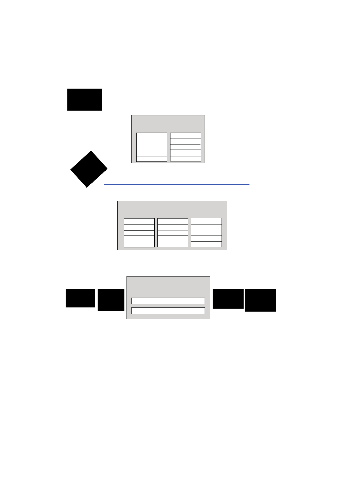
2 Functional Overview
The METTLER TOLEDO Fieldbus-Module is designed to exchange data between a serial sub-network and a higher level network.
For easy transfer is a Basic-Mode (see chapter 6.1, page 38) implemented for the most frequent commands. With the ExtendedMode (see chapter 6.2, page 40) is the full flexibility ensured.
2.1 Data exchange model
PLC
The PLC receives data into its internal input area via the fieldbus
network from the IN area of the
Fieldbus-Module.
Fieldbus-Module
The IN area of the Fieldbus-Module contains data received from
the weighing sensor.
I/O I/O
Inputs Outputs
IN Area OUT Area Local Data
(000h) (200h) (400h)
Actual Weight
Value
PLC-memory
Actual Weight
Value
Internal memory buffer
Module
Settings
and
Commands
Weighing sensor
Module
Settings
and
Commands
Fieldbus
The PLC sends data via the fieldbus network, from its internal
output area to the OUT area of
the Fieldbus-Module.
The OUT area of the FieldbusModule contains output data
sent from the Fieldbus-Module
to the weighing sensor.
8 Functional Overview
Input: Settings and Commands
Output: Weight value and Status
Page 9
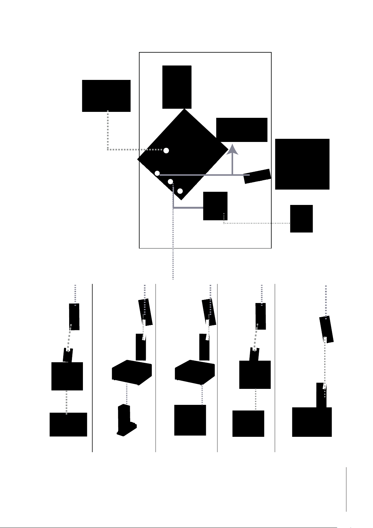
3 Set-up Checklist
PL
(e.g. Siemens S7
or Rockwell
RSLogix)
Legend
Included in delivery of Fieldbus-Module
C
1
User Manual
1 Fieldbus connector
2 PC connector
3 Subnet connector
4 Power connector
Fieldbus cable
2
3
4
Configuration cable
Power
connector
Power cable
Power supply
+24 VDC
D-Sub 9 male
11141979
open wires
ConBlock
PBK/PFK-APW
D-Sub 9 male D-Sub 9 male
RS232 Connection
cable
11601007
D-Sub 9 male D-Sub 9 male
WMC
Weigh Module
RS232 Connection
cable
11601007
WXS
Weigh Module
D-Sub 9 male
11141979
open wires
ConBlock
WMS
Weigh Module
D-Sub 9 male
RS232 Connection
cable
11601007
D-Sub 9 male
Industry Scale
e.g. BBK
9Functional Overview
Page 10

4 Step-by-Step Installation and Configuration
The following steps shall be performed to install and configure the weighing sensor and the Fieldbus-Module:
1. Configure the weighing sensor (see chapter 4.1, page 10)
2. DIN-Rail mounting (see chapter 4.2, page 11)
3. Connect the Fieldbus-Module to a PC for initial configuration (see chapter 4.3, page 11)
4. Connect the Fieldbus-Module to the weighing sensor (see chapter 4.4, page 12)
5. Connect the Fieldbus-Module to a power supply (see chapter 4.5, page 13)
6. Configure the Fieldbus-Module and activate the changes in the Fieldbus-Module (see chapter 4.6, page 14)
7. Connect the Fieldbus-Module to the network and check the LED indications (see chapter 5, page 17)
4.1 Configure the weighing sensor
Note
It is not possible to configure the weighing sensors, by use of the PC – Fieldbus-Module configuration cable connection.
Please refer to the configuration instructions of the individual weighing sensor.
4.1.1 Adjustment of interface communication parameters of the weigh modules
METTLER TOLEDO recommends to use the RS422 interface for if available the communication between weighing sensors and
the Fieldbus-Module. Configure the interface of the weigh module to a baud rate of 38400. Use MT-SICS command: COM (see
MT-SICS manual for more information).
Note
Set the data flow control to none if you connect any weighing sensor to a METTLER TOLEDO Fieldbus-Module!
METTLER TOLEDO recommends to set 19200 or 38400 baud to allow an update rate up to 92 updates.
Example: RS422, 38400 baud, 8 bit, no parity,1 stop bit and no handshake -> MT-SICS command: COM_1_8_3_0
4.1.2 Adjustment of interface communication parameters of other weighing sensors
The interface communication parameters can be set via the menu or with the data interface port. Please refer to the user manual
and/or the MT-SICS Reference Manual of the respective weighing sensor.
10 Step-by-Step Installation and Configuration
Page 11
A - Snap ON B - Snap OFF
D-sub 9 female
Fieldbus-Module
4.2 DIN-Rail mounting
To mount the Fieldbus-Module on a DIN-Rail follow the steps below:
Snap ON: To snap the Fieldbus-Module on, first press the Fieldbus-Module downward to compress the spring contacting the
DIN-Rail (1), then push the Fieldbus-Module against the DIN-Rail and release it to make it snap on (2).
Snap OFF: To snap the Fieldbus-Module off, push the Fieldbus-Module downward (1) and pull it away from the DIN-Rail (2)
to make it snap off from the DIN-Rail.
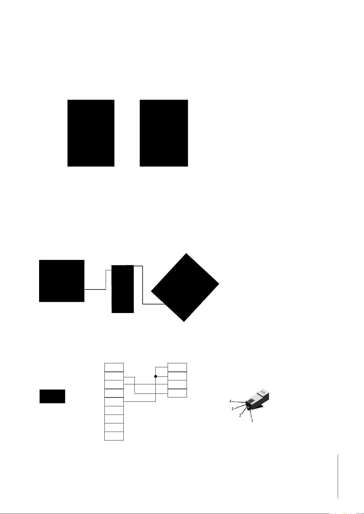
4.3 Connect the Fieldbus-Module to a PC for initial configuration
The PC connector is located at the bottom of the Fieldbus-Module. It is used to the configuration of the Fieldbus-Module. The
enclosed configuration cable shall be used (connector type is a Western Modular 4/4 on the Fieldbus-Module side).
Note
This cable connection is only suitable to configure the Fieldbus-Module, it cannot be used for weighing sensor configuration
(see also chapter 4.1).
Installs in PC’s
serial port
D-sub 9 female (PC)
RS232 RxD
5 1
9 6
(female)
RS232 TxD
Ground
1
2
3
4
Western Modular 4/4 connector
(Fieldbus-Module)
Ground
1
Ground
2
RxD
3
TxD
4
Western Modular 4/4
connector
5
6
7
8
9
11Step-by-Step Installation and Configuration
Page 12

4.4 Connect the Fieldbus-Module to the weighing sensor
The subnet connector is located at the bottom of the Fieldbus-Module and is used to connect a METTLER
TOLEDO weighing sensor equipped with either a RS232, a RS422 or a RS485 interface (configuration see
chapter 4.1). The respective pin assignment is shown in the table on next page.
Since the physical interface can be chosen by the Fieldbus-Module configuration dialog (see chapter 4.6.2), all necessary
signals for all three RS-versions are present at the D-Sub 9-connector.
Note
Make sure to connect only the necessary wires used in your application.
4.4.1 WMS, WM and WMH weighing sensor
DSub9
11141979
1 Black - -
2 Brown - TXD
3 Red - RXD
4 Orange - -
5 Yellow GND GND
6 Green Tx+ -
7 Blue Tx- -
8 Purple Rx+ -
9 Grey Rx- -
ConBlock (11152000) for the WMS weigh module
ConModule (42102811) for WM and WMH weigh module and platform
RS422 RS232
12 Step-by-Step Installation and Configuration
Page 13
1 2
Power Connector
51
96
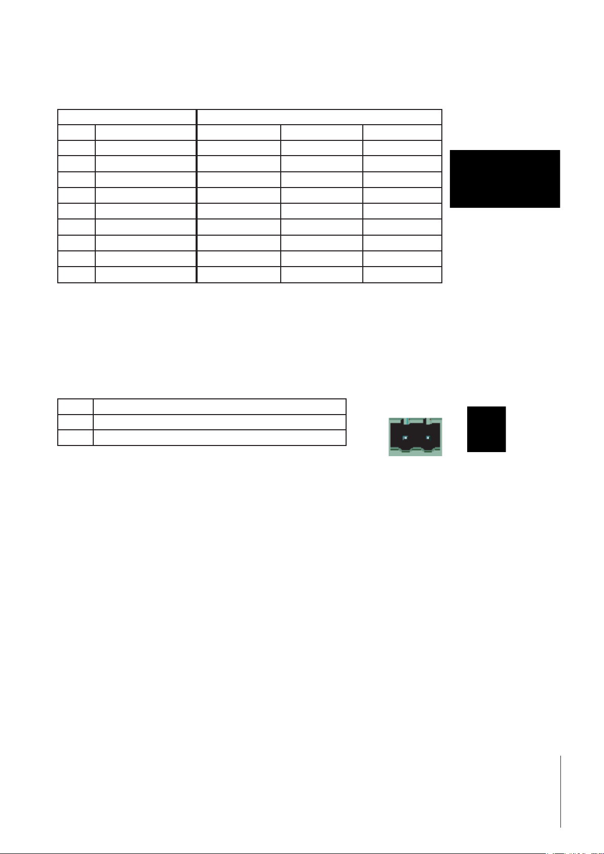
4.4.2 Other METTLER TOLEDO balances and weighing sensors
For other balances and weighing sensors with MT-SICS protocol and either a RS232, a RS422 or a RS485 interface please refer
to the respective manual of the weighing sensor to determine the pin assignment of its interface.
Subnet connector Interface Type of weighing sensor
Pin Description RS232 RS422 RS485
1 + 5Volt
2 RS232 RxD
3 RS232 TxD
4 Not connected
5 Ground
6 RS422 Rx+
7 RS422 Rx-
8 RS485+ / RS422 Tx+
9 RS485- / RS422 Tx-
P Wires to be used (depending on weighing sensor’s interface type)
Make sure to connect only the necessary wires depending on the weighing sensor’s interface.
P (TxD)
P (RxD)
P (GND) P (GND) P (GND)
P (Tx+)
P (Tx-)
P (Rx+) P (Rx+)
P (Rx-) P (Rx-)
(female)
4.5 Connect the Fieldbus-Module to a power supply
The power supply connector is located at the bottom of the Fieldbus-Module.
Pin Description
1 + 24V DC +/- 10%, 280 mA max.
2 GND
An appropriate connector (type MSTB 2.5/2-ST-5.08) with screw terminals is included in the delivery. The appropriate cable
diameter ranges from 0.2 mm2 to 2.5 mm2 (AWG 24 to AWG 12). Use 60/75 or 75°C copper (CU) wire only. The terminal
tightening torque must be between 0.5 - 0.8 Nm (5 - 7 lbs-in).
(2)
+
(1)
13Step-by-Step Installation and Configuration
Page 14

4.6 Configure the Fieldbus-Module
4.6.1 PC terminal software
The Fieldbus-Module provides a serial configuration dialog, which allows to configure the communication parameters of the
subnet communication by use of a PC. After power-up, the Fieldbus-Module sends an ASCII based configuration dialog via the
PC connector to a terminal or a PC. In case of using a PC, a terminal emulation program (such as hyper terminal which is a
standard component of Windows) shall be started before power-up of the Fieldbus-Module.
Use the following interface settings at your PC for the terminal program:
• Baud rate: 38400 bps.
• 8 data bits
• 1 stop bit
• No parity check
• No flow control
The dialog will show the following initial Menu on the screen (from a ProfiNet-Module):
The last saved settings will be displayed.
Note
The configuration dialog will be disabled after 60 seconds if no buttons are pressed.
You can always press the Esc button to display the main menu again.
Press the number of the option you want to change and then press enter. A new dialog will be displayed where you can enter
your new setting. After a new setting is entered, the main menu will be displayed again. The current setting will now show the
settings you have configured, but they will not be permanently stored until you save them to the flash by pressing "S" (save
configuration to flash) in the main menu.
To start using the new settings you must power down and restart the Fieldbus-Module.
14 Step-by-Step Installation and Configuration
Page 15

4.6.2 Weighing sensor interface
The Fieldbus-Module can communicate with weighing sensors using the following different interfaces:
• RS232, full duplex, no handshake.
• RS422, full duplex, no handshake (default).
• RS485, half duplex, no handshake.
Note
Set the handshake control to none if you connect any weighing sensor to a METTLER TOLEDO Fieldbus-Module!
4.6.3 Baudrate
The Fieldbus-Module can communicate using the following baudrates:
• 1200 bps
• 2400 bps.
• 4800 bps.
• 9600 bps.
• 19200 bps. (Default)
• 38400 bps.
• 57600 bps
4.6.4 Character format
The Fieldbus-Module supports the following character formats:
• 7 None 1 (7 data bits, no parity and 1 stop bit)
• 8 None 1 (8 data bits, no parity and 1 stop bit) (default)
• 7 Even 1 (7 data bits, Even parity and 1 stop bit)
• 7 Odd 1 (7 data bits, Odd parity and 1 stop bit)
4.6.5 Operation mode
The Fieldbus-Module can be used in two different modes (Detail see chapter 6.1, page 38 and chapter 6.2, page 40).
1. The Basic-Mode is the default operation mode and supports the most important MT-SICS commands
2. The Extended-Mode supports all MT-SICS commands and uses 32 bytes for communication.
4.6.6 Maximum response time
With the "Max response time"-option you can set the maximum time between two successive responses from the balance. If the
Fieldbus-Module does not receive a new response from the balance within the defined maximum response time, the FieldbusModule will indicate this communication problem by setting the connection status bit to "False" and the subnet status LED to
red (see chapter 7.2, page 48).
The connection status bit will be set to true (operational) again when cleared by the connection status clear bit.
The "Max response time" is defined to 60 seconds as default and can be changed between 10 sec and 9999 sec or completely
switched off. In that case the timeout feature is not working anymore. This might be useful for some applications where longer
periods of inactivity may occur.
4.6.7 Configuration from network
This menu point is only available in the ProfiNet IO-Module.
If "Configuration from network" is enabled, all parameters must be configured via network from the configuration program (e.g.
PLC). In this case no other configurations from the terminal program are possible.
The default setting for "Configuration from network" is enabled.
15Step-by-Step Installation and Configuration
Page 16

4.6.8 Automatic baudrate search
All Fieldbus-Modules have the ability to automatically search for correct baudrate and character format on the subnet side. If you
want to use automatic baudrate search you first have to configure the correct "Weighing sensor interface" under menu option 1,
after that you can start the search by pressing "A" (Perform Automatic baudrate search) in the main menu. The Fieldbus-Module
will send a command string to the weighing sensor in all different baudrates and character formats, and if the weighing sensor
responds, the Fieldbus-Module has found the correct settings.
Note
Automatic baudrate search can be used for subnet connection test. It will find no baudrate setting in case of failure.
Example of dialog using the automatic baudrate search option:
----------------------------------------------------------------------------------------------
Automatic baudrate search
----------------------------------------------------------------------------------------------
Searching with RS232 interface
Pressing ESCAPE interrupts the search.
Testing: 9600 bps, 8 none 1
Interface setting:
9600 bps, 8 none 1, no handshake.
Do you want to save the interface parameters? (Y/N)
>
If N (No) is pressed the Fieldbus-Module will reject the setting and return to the main menu.
If Y (Yes) is pressed the Fieldbus-Module will automatically save the new settings to the flash, therefore no additional "Save
configuration to flash" is necessary in the main menu.
Note
If an automatic baudrate search is used, the Fieldbus-Module will stop the normal communication with the weighing sensor.
Please refer the LED Indication Table (e.g. for Profibus-Module chapter 5.1.9) for explanations of the LED-signals during automatic baudrate search.
4.6.9 Save configuration to flash
To store the configuration permanently to the Fieldbus-Module you must press "S" (Save configuration to flash).
Before the new settings can be used, the Fieldbus-Module must be restarted by switching off and on the power supply from the
Fieldbus-Module.
16 Step-by-Step Installation and Configuration
Page 17

5 Fieldbus-Modules
5.1 Profibus-Module
The Profibus version of the METTLER TOLEDO Fieldbus-Module is called MT Profibus Module and has the METTLER TOLEDO
Part number: 42102809
5.1.1 General
The METTLER TOLEDO Profibus-Module is designed as a Profibus-DP slave (DPV0) according to EN 50170. It supports all
mandatory functions of a Profibus-DP slave.
A Profibus master (e.g. a PLC) can send commands and receive data from the Profibus-Module.
For the SIMATIC STEP 7 PLC there is a Engineering note and also a example, specific to METTLER TOLEDO products with SICS
communication protocol, available on www.mt.com/ind-APW-fieldbus-support. They significantly shorten integration time and
save valuable resources and development time for system integrators and end users.
5.1.2 Supported features
• Auto baudrate detection supported. Baudrate range: 9.6 kbit – 12 Mbit.
• Hardware prepared for DP-V1 extensions.
• Save / Load configuration in Flash supported.
• Address range: 1-99. The node address of the Profibus connection shall always be set via the configuration switches.
• Support all standard diagnostic messages according to standard EN 50170.
Profibus
5.1.3 Identification numbers
Identification number: 0x0642 Hex.
Product name: "MT Profibus Module"
Part number: 42102809
5.1.4 Profibus node address
Before installing the Profibus-Module in the Profibus network, the node address is to be set with two rotary
switches under the lid on the front. The address range is 1 to 99. The lower switch is used for the first digit
of the address (value x 10), the upper switch for the second digit of the address (value x 1).
Example
Address = 45 => lower switch to value 4 and upper switch to value 5.
Note
The node address cannot be changed during operation. A new address setting is valid after power-off and
power-on of the Profibus-Module.
17Step-by-Step Installation and Configuration
Page 18

5.1.5 Cabling
The Profibus-Module connects to a Profibus network with the female D-sub 9 connector on the front.
Pin Name Function
Housing Shield Connected to PE (connected to spring contacting the DIN-Rail).
1 Not connected 2 Not connected 3 B-Line Positive RxD/TxD-signals according to RS485 specification.
4 RTS Request to send*
5 GND BUS Isolated GND (RS485 side)*
6 +5V BUS Isolated +5 V (RS485 side)*
7 Not connected 8 A-Line Negative RxD/TxD-signals according to RS485 specification.
9 Not connected -
* +5 V BUS and GND BUS are used for bus termination. Some devices, like optical transceivers (RS485 to fiber optics) might
require external power supply from these pins (max. 80 mA). RTS is used in some equipment to determine the direction of
transmission. In standard applications only A-line, B-line and Shield are used.
5.1.6 Bus termination
The first and the last device of each Profibus line must be terminated with termination resistors to avoid reflections on the bus.
Also the METTLER TOLEDO Profibus-Module can be installed as the first or the last device of a Profibus line. The termination is
typically done by switching on the termination switch of the Profibus connector of the bus cable at the first and last device. At
all other devices of a Profibus line the termination switch should be turned off.
5.1.7 GSD configuration file
Each Profibus-Master (e.g. PLC) requires a GSD file for integration of the METTLER TOLEDO Profibus-Module. The GSD file for
the METTLER TOLEDO Profibus-Module is provided on www.mt.com/ind-APW-fieldbus-support.
5.1.8 Configure and start the Profibus network
For general installation and configuration see chapter 4, page 10.
The Profibus node address must be configured shown in chapter 5.1.4.
Correct communication between the Profibus-Module and the weighing sensor is indicated by the following LED status (see
chapter 5.1.9): 5 green steady, 6 green steady. Refer to chapter 7.3 if LED’s show different status.
Note
The integration shall be carried out by PLC system experts. The respective support for PLC systems is not under METTLER
TOLEDO responsibility.
18 Step-by-Step Installation and Configuration
Page 19

5.1.9 LED indication table
LED Indication Description
1 – Network status Off Profibus not online
Green, steady Profibus online
2 – Profibus status Off Profibus not offline
Red, steady Profibus offline
3 – Reserved - Not used
4 – Fieldbus diagnostic Off No diagnostic present
Red, 1 Hz-flashing Error in configuration from the Profibus master side
Red, 2 Hz-flashing User parameter data error
Red, 4 Hz-flashing Error in initialization of Profibus ASIC (internal fault)
5 – Subnet status Off Power Off
Green, steady Communication with weighing sensor OK
Green, flashing Receiving data from weighing sensor
Red, steady Communication with weighing sensor failed (timeout)
6 – Device status Off Power Off
Green, steady Profibus-Module initialized and running
Green, flashing Performing auto baudrate detection
Red, steady Unrecoverable error
Red, flashing Auto baudrate detection failed
Profibus
19Step-by-Step Installation and Configuration
Page 20

5.2 DeviceNet-Module
The DeviceNet version of the METTLER TOLEDO Fieldbus-Module is called MT Devicenet Module and has the METTLER TOLEDO
Part number: 42102810.
5.2.1 General
The DeviceNet-Module functions as a DeviceNet adapter according to EN 50325-2. It supports all mandatory functions for
polled I/O slave messaging of a DeviceNet adapter.
It acts as a device slave on the network and presents the weighing sensor data to the master controller.
As of RSLogix5000 Version 16, a complimentary open-source Rockwell Automation Logis5000 function block and faceplates
with a Engineering note, specific to METTLER TOLEDO products with SICS communication protocol, available on www.mt.com/
ind-APW-fieldbus-support. They significantly shorten integration time and save valuable resources and development time for
system integrators and end users.
5.2.2 Supported features
• MAC ID and baudrate can be set via onboard switches.
• Explicit messaging
• Polled I/O
• Bit-strobed I/O
• Change-of-state / Cyclinc I/O
• Galvanically isolated bus electronics
• All standard DeviceNet baudrates from 125 kbit/s to 500 kbit/s are supported. Baudrate and node address shall be set via
the configuration switches.
• Implemented objects:
• DeviceNet objects:
1. Identity object, class 01h
2. Message router object, class 02h
3. DeviceNet object, class 03h
4. Assembly object, class 04h
5. Connetion object, class 05h
6. Acknowledge handler object, class 2Bh
• Vendor specific objects:
7. I/O data Input mapping object, class A0h
8. I/O data output mapping object, class A1h
9. Diagnostic object, class AAh
10. Parameter data Input mapping object, class B0h
11. Parameter data output mapping object, class B1h
5.2.3 Identification numbers
Vendor ID: 90
Device ID: 12
Product code: 40
Product name: "MT Devicenet Module"
Part number: 42102810
20 Step-by-Step Installation and Configuration
Page 21
5.2.4 Network configuration
5.2.4.1 Mac address
Before installing the DeviceNet-Module on a DeviceNet network, it must have a unique Mac ID. The Mac ID
shall be set between 0 and 63.
The Mac ID is configured by the DIP-switches 3 to 8 under the lid on the front.
MAC ID Sw. 3 (MSB) Sw. 4 Sw. 5 Sw. 6 Sw. 7 Sw. 8 (LSB)
0 OFF OFF OFF OFF OFF OFF
1 OFF OFF OFF OFF OFF ON
2 OFF OFF OFF OFF ON OFF
3 OFF OFF OFF OFF ON ON
- - - - - - -
62 ON ON ON ON ON OFF
63 ON ON ON ON ON ON
5.2.4.2 Baudrate
There are three different baudrates for DeviceNet: 125kbit/s, 250kbit/s and 500kbit/s.
Switches 1 and 2 are used to set the baudrate of the DeviceNet-Module.
Baudrate Sw. 1 Sw. 2
125k OFF OFF
250k OFF ON
500k ON OFF
(reserved) ON ON
DeviceNet
5.2.5 Cabling
The DeviceNet-Module connects to a DeviceNet network with a connector with screw terminals at the front.
Pin Signal Description
1 V- Negative supply voltage*
2 CAN_L CAN_L bus line
3 SHIELD Cable shield
4 CAN_H CAN_H bus line
5 V+ Positive supply voltage*
Note
* The bus interface shall be externally supplied with 24V DC +/- 10%.
5.2.6 EDS configuration file
During configuration of the DeviceNet-Module at the DeviceNet master scanner (e.g. PLC), an EDS file (Electronic Data Sheet)
is required. This EDS file for the DeviceNet-Module is provided on www.mt.com/ind-APW-fieldbus-support.
21Step-by-Step Installation and Configuration
Page 22

5.2.7 Configure and start the DeviceNet network
For general installation and configuration see chapter 4, page 10.
The DeviceNet address (MAC ID) and baudrate must be configured shown in chapter 5.2.4.1 and 5.2.4.2.
Correct communication between the DeviceNet-Module and the weighing sensor is indicated by the following LED status (see
chapter 5.2.8): 5 green steady, 6 green steady. Refer to chapter 7.3 if LED’s show different status.
Note
The integration shall be carried out by PLC system experts. The respective support for PLC systems is not under METTLER
TOLEDO responsibility.
5.2.8 LED indication table
LED Indication Description
1 – Network status Off Not online
Green, steady Link OK, not connected
Green, flashing Online, not connected
Red, steady Critical link failure
Red, flashing Connection timeout
2 – DeviceNet status Off Power Off
Green, steady Device operational
Green, flashing Data size bigger than configured
Red, steady Unrecoverable fault
Red, flashing Minor fault
3 – Reserved - Not used
4 – Reserved - Not used
5 – Subnet status Off Power Off
Green, steady Communication with weighing sensor OK
Green, flashing Receiving data from weighing sensor
Red, steady Communication with weighing sensor failed
(timeout)
6 – Device status Off Power Off
Green, steady DeviceNet-Module initialized and running
Green, flashing Performing auto baudrate detection
Red, steady Unrecoverable error
Red, flashing Auto baudrate detection failed
22 Step-by-Step Installation and Configuration
Page 23

5.3 EtherNet/IP-Module
The EtherNet/IP version of the METTLER TOLEDO Fieldbus-Module is called MT Ethernet/IP Module and has the METTLER
TOLEDO Part number: 42102860
5.3.1 General
The EtherNet/IP-Module functions as an EtherNet/IP adapter according to EN 50325-2. It supports all mandatory functions for
polled I/O slave messaging of an EtherNet/IP adapter.
The Industrial Ethernet Protocoll (EtherNet/IP) was originally developed by Rockwell Automation and is now managed by the
Open DeviceNet Vendors Associaton (ODVA).
EtherNet/IP is standardized in the International standard IEC 61158.
As of RSLogix5000 Version 16, a complimentary open-source Rockwell Automation Logis5000 function block and faceplates
with a Engineering note, specific to METTLER TOLEDO products with SICS communication protocol, available on www.mt.com/
ind-APW-fieldbus-support.They significantly shorten integration time and save valuable resources and development time for
system integrators and end users.
5.3.2 Supported features
• Supported shielded (FTP) and unshielded (UTP) cables
• Flexible file system providing both volatile and non-volatile storage areas
• Security framework
• Integrated FTP server provides easy file management using standard FTP clients.
• Server side include (SSI) capability
• Web server
• E-mail client (messages can be triggered by data events or directly by the application)
• All standard EtherNet/IP baudrate 10/100 Mbit are supported. It will detect the actual transmission speed of the bus automatically.
• The node address of the EtherNet/IP connection shall always be set via the IPConfig-Tool (see chapter 5.3.9)
• The following CIP-objects are implemented:
• Mandatory objects:
1. Identity object, class 01h
2. Message router object, class 02h
3. Assembly object, class 04h
4. Connection manager, class 06h
5. Port object, class F4h
6. TCP/IP interface object, class F5h
7. Ethernet link object, class F6h
• Vendor specific objects:
8. I/O data input mapping object, class A0h
9. I/O data output mapping object, class A1h
10. Diagnostic object, class AAh
11. Parameter data input mapping object, class B0h
12. Parameter data output mapping object, class B1h
EtherNet/IP
23Step-by-Step Installation and Configuration
Page 24

1 8
5.3.3 Identification numbers
Vendor ID: 666
Device ID: 12
Product code: 42860
Product name: "MT Ethernet/IP Module"
Part number: 42102860
5.3.4 Network configuration
5.3.4.1 IP address
Make sure each node on the network has a unique IP address. The IP settings of the EtherNet/IP-Module can
be configured in various ways. It is recommended to use the IPConfig-Tool (see chapter 5.3.9) for configuring the IP-settings.
The IP address of the EtherNet/IP-Module can be also set with the configuration switches in the range
192.168.0.1 – 192.168.0.254.
If the switches are set to zero, the settings are specified by the system file "ethcfg.cfg" e.g. with the IPConfigTool (see chapter 5.3.9).
Note that the switches are read once during startup; any changes require a reset in order to have effect.
SW1 SW2 SW3 SW4 SW5 SW6 SW7 SW8 DHCP Subnet Gateway IP
OFF OFF OFF OFF OFF OFF OFF OFF (settings determined by ‘ethcfg.cfg’)
OFF OFF OFF OFF OFF OFF OFF ON OFF 255.255.255.0 192.168.0.255 192.168.0.1
OFF OFF OFF OFF OFF OFF ON OFF OFF 255.255.255.0 192.168.0.255 192.168.0.2
… … … … … … … … … … … …
ON ON ON ON ON ON ON OFF OFF 255.255.255.0 192.168.0.255 192.168.0.254
ON ON ON ON ON ON ON ON (invalid setting)
To read and write the IP configuration is also possible to use the EtherNet/IP website (e.g. http://192.168.0.1).
5.3.5 Cabling
Pin Signal
Housing Cable shield
1 TD+
2 TD-
RJ45
3 RD+
4 Termination
5 Termination
6 RD-
7 Termination
8 Termination
5.3.6 EDS configuration file
The EDS file is provided on www.mt.com/ind-APW-fieldbus-support and has the function of an electronic data sheet and includes all parameter and options that an EtherNet/IP device supports. The EtherNet/IP-Module requires one EDS file that contains
the necessary definitions for the Basic and the Extended-Mode.
24 Step-by-Step Installation and Configuration
Page 25

5.3.7 Configure and start the EtherNet/IP network
For general installation and configuration see chapter 4, page 10.
The IP address must be configured shown in chapter 5.3.4.1.
Correct communication between the EtherNet/IP-Module and the weighing sensor is indicated by the following LED status (see
chapter 5.3.8): 5 green steady, 6 green steady. Refer to chapter 7.3 if LED’s show different status.
Note
The integration shall be carried out by PLC system experts. The respective support for PLC systems is not under METTLER
TOLEDO responsibility.
5.3.8 LED indication table
LED Indication Description
1 – Module status Off (no power)
Green, steady Normal operation
Green, flashing Stand by, not initialized
Red Major fault
Red, flashing Minor fault
Alternating Red/Green (self test)
2 – Network status Off No IP address (or no power)
Green, steady EtherNet/IP connection(s) established
Green, flashing No EtherNet/IP connection(s) established
Red Duplicate IP address detected
Red, flashing One or several connections time out
Alternating Red/Green (self test)
3 – Link Off No link (or power off)
Green Connected to an Ethernet network
4 – Activity Off No Ethernet activity (or no power)
Green Receiving or transmitting Ethernet packet
5 – Subnet status Off Power Off
Green, steady Communication with weighing sensor OK
Green, flashing Receiving data from weighing sensor
Red, steady Communication with weighing sensor failed (timeout)
6 – Device status Off Power Off
Green, steady EtherNet/IP-Module initialized and running
Green, flashing Performing auto baudrate detection
Red, steady Unrecoverable error
Red, flashing Auto baudrate detection failed
EtherNet/IP
5.3.9 IPConfig-Tool
The EtherNet/IP-Module has to be configured for the same I/O size and IP-settings as in the PLC configuration. The IPConfig-Tool
(can be found on www.mt.com/ind-APW-fieldbus-support) can be used to configure the IP settings of all EtherNet/IP-Modules.
The IPConfig-Tool scans the network for EtherNet/IP-Modules. To configure the settings manually (default DHCP is activated)
double click on the desired module and enter the desired IP-settings.
25Step-by-Step Installation and Configuration
Page 26

5.4 EtherNet/IP Configuration for Rockwell Add-on-Profile
After installation the EtherNet/IP-Module must be configured in the PLC.
5.4.1 Connecting the EtherNet/IP-Module
Refer to the EtherNet/IP-Module instructions for installation and operation for details.
On chapter 4.4.1 you can find information about the RS422 cable connection between the ConModule to the DeviceNet-Module.
5.4.2 PLC configuration
To create a new configuration, open the file menu and select "New". In the appearing dialogue select the desired type of PLC,
in this case the type 1756-L55 is used. Also enter a name for the controller and select chassis type, slot number and project
path. To accept the settings press "OK".
Then add the Ethernet I/O-Module. Right click on the I/O Configuration directory in the navigation list to the left as seen.
26 Step-by-Step Installation and Configuration
Page 27

Click on "New Module" and select the desired Ethernet-Module, in this case the Ethernet-Bridge. This Module is the ScannerModule in the PLC.
Then enter the desired settings and press "Finish".
EtherNet/IP
27Step-by-Step Installation and Configuration
Page 28

5.4.3 EtherNet/IP-Network configuration
To add the METTLER TOLEDO EtherNet/IP-Module (Generic Ethernet Module) to the configuration in the PLC, the program setting
must be in offline mode. Add the module with a right click on the "EtherNet/IP-Bridge" in the I/O Configuration, and select "New
Module".
Now a dialogue window will appear. In this dialogue window, select "Generic Ethernet Module" and press "OK".
In the next dialogue window, RSLogix 5000 will ask for information regarding the communication to the METTLER TOLEDO
Ethernet/IP-Module. First enter a name for the METTLER TOLEDO Ethernet/IP-Module (1). In the example below we call it
METTLER_TOLEDO. This name will create a tag in RSLogix 5000, which can be used to access the memory location in the
PLCs memory where the data for the METTLER TOLEDO Ethernet/IP-Module will be stored. A description can also be added, but
that is optional.
28 Step-by-Step Installation and Configuration
Page 29

Next step is to select the Comm Format, which tells RSLogix 5000 the format of the data (2). In our example, we have selected
Data-INT, which will represent the data in the METTLER TOLEDO Ethernet/IP-Module as a field of 16-bit values. It is also possible to select Data-SINT, which will represent the data as 8-bit values, and Data-DINT, which will represent it as 32 bit values.
In our case (Basic-Mode we are using 64-bit (8 byte) values of input and 16-bit (2 byte) of output data. In this case, the size
that we enter in (3) is: 4×16-bit as input and 1×16-bit as output value. If we had been using other data type like Data-SINT or
Data-DINT, we would have to recalculate the size to match the data type.
I/O data is accessed in input instance 100 and output instance 150, so these values have to be entered as the instance values
for input and output (4). The size of the input connection and the output connection shall correspond to the size that we have
configured the METTLER TOLEDO Ethernet/IP-Module for.
The METTLER TOLEDO Ethernet/IP-Module does not have a configuration assembly instance by default, but RSLogix 5000
requires a value for this anyway. An instance value of 0 or 255 is not a valid instance number, but any other non-zero value
will work, here we have selected the value 1 (5). The data size of the configuration instance has to be set to 0, otherwise the
configuration instance will be accessed and the connection will be refused (6). As a final step we enter the IP address that we
have configured for the module, here 192.168.1.50 (7).
EtherNet/IP
29Step-by-Step Installation and Configuration
Page 30

In this tab we will enter a value for the time between each scan of the Module. In this example, we have set the interval to 50ms
to reduce the network load. Make sure that Inhibit Module is not checked. After this, press "OK".
Note
Once settings are saved ("OK" clicked), the Comm Format cannot be changed. The Generic Ethernet-Module must be deleted
and then re-entered if a different Comm Format is desired. All other settings may be edited.
Now the METTLER TOLEDO EtherNet/IP-Slave has been added to the I/O Configuration in RSLogix 5000.
30 Step-by-Step Installation and Configuration
Page 31

5.5 ProfiNet IO-Module
The ProfiNet IO version of the METTLER TOLEDO Fieldbus-Module is called MT Profinet Module and has the METTLER TOLEDO
Part number: 42102859
5.5.1 General
The ProfiNet IO-Module functions as a ProfiNet IO slave according to IEC 61784 (CPF-3/3) and supports ProfiNet IO baudrate
100 Mbit.
For the SIMATIC STEP 7 PLC there is a Engineering note and also a example, specific to METTLER TOLEDO products with SICS
communication protocol, available on www.mt.com/ind-APW-fieldbus-support. They significantly shorten integration time and
save valuable resources and development time for system integrators and end users.
5.5.2 Supported features
• Supported shielded (FTP) and unshielded (UTP) cables
• Flexible file system providing both volatile and non-volatile storage areas
• Security framework
• Integrated FTP server provides easy file management using standard FTP clients.
• Server side include (SSI) capability
• Web server
• E-mail client (messages can be triggered by data events or directly by the application)
• Only slot 0 and 1 is used for the ProfiNet IO-Module and no subslots.
• The standard ProfiNet IO baudrate 100 Mbit is supported. It will detect the actual transmission speed of the bus automatically.
• The note address of the ProfiNet IO connection shall always be set via the IPConfig-Tool (see chapter 5.5.9).
5.5.3 Identification numbers
Vendor ID: 142
Device ID: 1111
Product name: "MT Profinet Module"
Part number: 42102859
5.5.4 Network configuration
5.5.4.1 IP address
Make sure each node on the network has a unique IP address. The IP settings of the ProfiNet IO-Module can be configured in
various ways. It is recommended to use the IPConfig-Tool (see chapter 5.5.9) for configuring the IP-settings.
To read and write the IP configuration is also possible to use the ProfiNet IO website (e.g. http://192.168.0.1).
5.5.4.2 Sub-network configuration
An additional parameter according to the sub-network parameters (see chapter 4.6.7, page 16) is available to define how the
sub-network parameters will be configured.
ProfiNet IO
31Step-by-Step Installation and Configuration
Page 32

5.5.5 Cabling
1 8
Pin Signal
Housing Cable Shield
1 TD+
2 TD-
RJ45
3 RD+
4 Termination
5 Termination
6 RD-
7 Termination
8 Termination
5.5.6 GSDML configuration file
The GSDML file is provided on www.mt.com/ind-APW-fieldbus-support and has the function of an electronic data sheet and
includes all parameter and options that an ProfiNet IO device supports. The ProfiNet IO-Module requires one individual GSDML
file that contains two Module definitions: Module 1: Basic-Mode and Module 2: Extended-Mode.
5.5.7 Configure and start the ProfiNet IO network
For general installation and configuration see chapter 4, page 10.
The ProfiNet IO MAC and IP address can be read out with the IPConfig-Tool (see chapter 5.5.9) or from the printed label on the
ProfiNet IO-Module. Use this information to configure the PLC.
Correct communication between the ProfiNet IO-Module and the weighing sensor is indicated by the following LED status (see
chapter 5.5.8): 5 green steady, 6 green steady. Refer to chapter 7.3 if LED’s show different status.
Note
The integration shall be carried out by PLC system experts. The respective support for PLC systems is not under METTLER
TOLEDO responsibility.
32 Step-by-Step Installation and Configuration
Page 33

5.5.8 LED indication table
LED Indication Description
1 – Comm. status
2 – Module status Off No power or not initialized
3 – Link / Activity Off No link or power off
4 – (not used) - -
5 – Subnet status Off Power Off
Off
Green, steady
Green, flashing
Green, steady Initialized, no error
Green, 1 flash Diagnostic data available
Green, 2 flashes Blink. Used by engineering tools for identification
Red, 1 flash
Red, 3 flashes No station name or no IP address assigned
Red, 4 flashes Internal error
Green Link established
Green, flashing Receiving / transmitting data
Green, steady Communication with weighing sensor OK
Green, flashing Receiving data from weighing sensor
Red, steady Communication with weighing sensor failed (timeout)
Offline
- No connection with IO Controller
Online, RUN
- Connection with IO Controller established
- IO Controller in RUN state
Online, STOP
- Connection with IO Controller established
- IO Controller in STOP state
Configure error
- Too many modules / submodules
- I/O size or configuration mismatch
6 – Device status Off Power Off
Green, steady ProfiNet IO-Module initialized and running
Green, flashing Performing auto baudrate detection
Red, steady Unrecoverable error
Red, flashing Auto baudrate detection failed
5.5.9 IPConfig-Tool
The ProfiNet IO-Module has to be configured for the same I/O size and IP settings as in the PLC configuration. The IPConfig-Tool
(can be found on www.mt.com/ind-APW-fieldbus-support) can be used to configure the IP settings of all ProfiNet IO-Modules.
The IPConfig-Tool scans the network for ProfiNet IO-Modules. To configure the settings manually (default DHCP is deactivated)
double click on the desired module and enter the desired IP-settings.
ProfiNet IO
33Step-by-Step Installation and Configuration
Page 34

5.6 CC-Link Module
The CC-Link version of the METTLER TOLEDO Fieldbus-Module is called MT CC-Link Module and has the METTLER TOLEDO Part
number: 30038775.
5.6.1 General
The CC-Link Module functions as CC-Link slave according to BTP-05026-D and supports baud rates from 156kb/s to 10Mbit/s.
5.6.2 Supported features
• All mandatory functions of a CC-Link remote device
• Baud rate set via onboard switches
• Address range: 1-64 (Basic-Mode), 1-61 (Extended-Mode)
• CC-Link Version 1.0
5.6.3 Identification numbers
Vendor ID: 1715
Model code: 0x0033 (weight indicator)
Product name: "MT CC-Link Module"
Part number: 30038775
5.6.4 Network configuration
5.6.4.1 Station range
1-64 (if more than one station is used then the upper limit will be lowered with the same number of stations).
The station number of the CC-Link connection shall always be set via the configuration switches of the CCLink Module. The Module will be delivered with station number 01.
Set the CC-Link station number by using the switches as follows:
Station number = (switch B * 10) + (switch A * 1).
5.6.4.2 Baud rate
Choose the desired baud rate using the baud rate switch.
0. 156k
1. 625k
2. 2.5M
3. 5M
4. 10M
34 Step-by-Step Installation and Configuration
Page 35

5.6.5 Cabling
Pin Signal
1 DA (Communication signal)
2 DB (Communication signal)
3 DG (Digital ground)
4 Shield (Cable shield)
5 FG / PE (Frame ground)
5.6.6 Configuration and start the CC-Link network
For general installation and configuration see chapter 4, page 10.
Correct communication between the CC-Link Module and the weighing sensor is indicated by the following LED status (see
chapter 5.6.8): 5 green steady, 6 green steady. Refer to chapter 7.3 if LED’s show different status.
Note
The integration shall be carried out by PLC system experts. The respective support for PLC systems is not under METTLER
TOLEDO responsibility.
5.6.7 Operation
The tables below show the specific data area layout for the CC-Link Module.
Due to CC-Link’s rigid data structure with reserved space for separated bit data and word data, it is required to initialise larger
data areas than with other METTLER TOLEDO Fieldbus-Modules. This is the reason why this layout is different than our other
Fieldbus Modules.
Basic-Mode uses 12 bytes in the output area and 12 bytes in the input area whilst Extended-Mode requires 48 bytes in the
output area and 48 bytes in the input area. In Basic-Mode, the CC-Link device requires 1 station whilst in Extended-Mode 4
stations are required.
5.6.7.1 Basic-Mode
Output register
Bit 7 6 5 4 3 2 1 0
Byte 0 Reserved (Bit 3-7) STC QTB QDV
Byte 1 Reserved
Byte 2 Reserved
Byte 3 Reserved
Byte 4 CMD (RWw0, least significant byte)
Input register
Bit 7 6 5 4 3 2 1 0
Byte 0 Reserved (Bit 3-7) ST RTB RDV
Byte 1 Reserved
Byte 2 Reserved
Byte 3 Reserved
Byte 4 RES (RWr0, least significant byte)
Byte 5 Scale Response Status (BRS) (RWr0, most significant byte)
Byte 6 Weight Unit (WU) (RWr1, least significant)
Byte 7 Reserved
Byte 8-11 Weight Value (WV) (RWr2-RWr3)
CC-Link
35Step-by-Step Installation and Configuration
Page 36

5.6.7.2 Extended-Mode
Output register
Bit 7 6 5 4 3 2 1 0
Byte 0 Reserved (Bit 3-7) STC QTB QDV
Byte 1 Reserved
… …
Byte 15 Reserved
Byte 16 Reserved (bit 5-7) CMD (RWw0, least significant byte)
Byte 17 …
Byte 18 MT-SICS Command (1st byte)
Byte 19 MT-SICS Command (2nd byte)
… …
th
Byte n MT-SICS Command (n
Byte n+1 CR (Carriage return 0Dhex)
Byte n+2 LF (Line feed 0Ahex)
Byte n+3 00hex
… …
Byte 47 00hex
Input register
Bit 7 6 5 4 3 2 1 0
Byte 0 Reserved (Bit 3-7) ST RTB RDV
Byte 1 Reserved
… …
Byte 15 Reserved
Byte 16 Reserved (bit 5-7) RES (RWr0, least significant byte)
Byte 17 Scale Response Status (BRS) (RWr0, most significant byte)
Byte 18 Weight Unit (WU) (RWr1, least significant byte)
Byte 19 Reserved
Byte 20-23 Weight Value (WV) (RWr2-RWr3)
Byte 24 MT-SICS Command (1
Byte 25 MT-SICS Command (2nd byte)
… …
Byte n MT-SICS Command (nth byte)
Byte n+1 CR (Carriage return 0Dhex)
Byte n+2 LF (Line feed 0Ahex)
Byte n+3 00hex
… …
Byte 47 00hex
byte)
st
byte)
36 Step-by-Step Installation and Configuration
Page 37

5.6.8 LED indication table
LED Indication Description
1 – ERRL Red CRC error; illegal station number or baud rate
Off Normal operation
2 – EDLED Green Receiving data
Off Not receiving data
3 – RUN Green Normal operation
Off No network connction or timeout (or no power)
4 – SDLED Green Transmitting data
Off No data transmission (or no power)
5 – Subnet status Off Power Off
Green, steady Communication with weighing sensor OK
Green, flashing Receiving data from weighing sensor
Red, steady Communication with weighing sensor failed (timeout)
6 – Device status Off Power Off
Green, steady CC-Link Module initialized and running
Green, flashing Performing auto baudrate detection
Red, steady Unrecoverable error
Red, flashing Auto baudrate detection failed
5.6.9 Operations
CC-Link Module uses a specific data area layout. For more details please see chapter 5.6
37Step-by-Step Installation and Configuration
CC-Link
Page 38

6 Operations
The Fieldbus-Module operates in the Basic-Mode with 2 output bytes and 8 input bytes and in the Extended-Mode with 32 output
bytes and 32 input bytes in the I/O-area of the PLC.
6.1 Basic-Mode
The Basic-Mode instructions contain the most important commands to operate a weighing sensor (see chapter 6.3 for detailed
information of supported commands). The coding of these commands is short and simple and allows a simple PLC interface
that requires only 2 bytes in the output area and 8 bytes in the input area of the PLC. In this mode the Fieldbus-Module encodes
and decodes the ASCII strings and converts the weight values.
The PLC interface will operate in the Basic-Mode if the user has chosen this option during the configuration of the Fieldbus master
and the Fieldbus-Module has been set into the same mode during the Fieldbus-Module configuration dialog, see chapter 4.6.6.
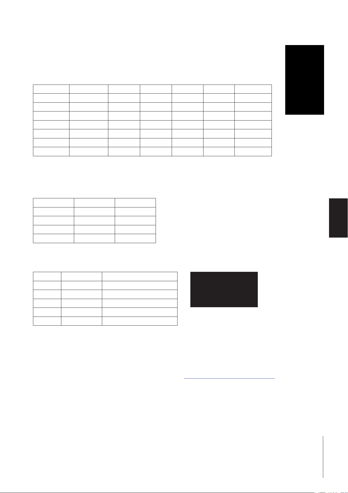
6.1.1 Output register Basic-Mode: 2 bytes
This part contains the information that is sent from the PLC to the weighing sensor i.e. the commands that are sent from the
PLC program to the weighing sensor.
Bit 7 6 5 4 3 2 1 0
Byte 1 Reserved (bit 3-7) STC QTB QDV
Byte 2 Reserved (bit 5-7) CMD (bit 0-4)
Query data valid (QDV)
The PLC program sets this bit to true if the code in the CMD field is valid and respectively to false if the data in the CMD field is not
valid. This bit is controlled by the PLC program and processed by the Fieldbus-Module. It is not visible to the weighing sensor.
Query toggle bit (QTB)
The PLC program toggles this bit (from 0 to 1 or 1 to 0) every time a new command shall be executed. Before the bit is toggled,
a valid command code must be present in the CMD field. This bit is controlled by the PLC program and processed by the
Fieldbus-Module. It is not visible to the weighing sensor.
Connection status clear (STC)
This bit is used as an acknowledge signal for the connection status bit (ST), see chapter 6.1.2. It is low (false) during normal
operation. If the connection between the balance and the Fieldbus-Module is lost ST is set false by the Fieldbus-Module. The PLC
reads this bit and acknowledges its value by setting STC true. If STC is true the Fieldbus-Module clears ST back to true. This in
turn is being read by the PLC and the STC is set back to false again. This short handshake process ensures that each connection
failure is properly sensed and taken care of by the PLC.
Reserved bits
These bits are reserved for future use and are not visible to the weighing sensor.
Weighing sensor command code (CMD)
The PLC program uses this field to specify the selected weighing sensor command. The Fieldbus-Module will convert this code
into the ASCII coded MT-SICS-command string. The maximum number of commands is limited to 32 (Basic-Mode only). See
chapter 6.3 for detailed information of supported commands.
38 Operation
Page 39

6.1.2 Input register Basic-Mode: 8 bytes
This part contains the information that is sent from the weighing sensor to the PLC, i.e. the response strings that are generated
by the weighing sensor as answers to the query commands from the PLC.
Bit 7 6 5 4 3 2 1 0
Byte 1 ST RTB RDV
Byte 2 Reserved (bit 5-7) RES (bit 0-4)
Byte 3 Weighing Sensor (Balance) Response Status (BRS)
Byte 4 Weight Unit (WU)
Byte 5-8 Weight Value (WV)
Response data valid (RDV)
The Fieldbus-Module will set the response data valid (RDV) bit to true if the data in the weighing sensor (Balance) response
bytes 2 – 8 (RES, BRS, WU and WV) are valid and comply with the query specified in the weighing sensor query command.
Response toggle bit (RTB)
The Fieldbus-Module will set the response toggle bit (RTB) to the same value as the query toggle bit after it has sent the query
command to the weighing sensor. At the same time, the Fieldbus-Module will reset the response data valid bit (RDV). Both bits
are controlled by the Fieldbus-Module and are not visible to the weighing sensor.
Connection status bit (ST)
This bit indicates the status of the serial connection between the Fieldbus-Module and the weighing sensor. It is controlled by the
Fieldbus-Module and not visible to the weighing sensor. This bit is valid at any time and independent from the RDV bit.
True = serial connection to weighing sensor operational
False = serial connection to weighing sensor not operational (timeout)
Reserved bits
These bits are reserved for future use and are not visible to the weighing sensor.
Weighing sensor response code (RES)
This field is used to indicate the response code that the Fieldbus-Module has received from the weighing sensor. It is controlled
by the Fieldbus-Module and not visible to the weighing sensor. During regular operation, it should always have the same value
as the CMD code if RDV=True. If the two codes differ, the serial link between the PLC and the weighing sensor may have lost
synchronization. In this case a reset command should be issued to re-synchronize the system. Please refer to the flow chart in
chapter 6.7.2 for details.
Weighing sensor (Balance) response status (BRS) [Byte 3]
BRS contains the status information that the Fieldbus-Module has received from the weighing sensors response message. In
most of the MT-SICS response strings this is the status information (S, D, A, I, +, -, L) following the first blank character after the
MT-SICS-command. The Fieldbus-Module will decode the response message from the weighing sensor, will suppress unnecessary information and will encode the RES status field as defined in chapter 7.1 of this document. The values shown in this table
are the hexadecimal equivalent of the ASCII values (S, D, A, I, +, -, L).
Weight unit (WU) [Byte 4]
WU contains the hexadecimal equivalent of the weight unit as defined in chapter 6.4.
Weight value (WV) [Byte 5-8]
WV contains the weight value if applicable for the selected command. The Fieldbus-Module will decode the ASCII coded weight
value that it has received from the weighing sensor, will suppress unnecessary information and will convert it into a 32 bit single
precision real number according to IEEE 754. The weight value is presented in Motorola format MSB in byte 5 and LSB in byte
8. If no weight value is associated with the selected command, the Fieldbus-Module will set this field to 0000hex.
39Operation
Page 40

Note
If the weight value is not indicated correctly on the PLC please check the endian order. The bytes from the communicator
(Fieldbus-Module) is in big endian order (MSB first) but the PLC could use little endian (LSB first). To achieve correct indication
please swap byte 5 and 8 and swap byte 6 and 7 in the PLC.
6.2 Extended-Mode
The Extended-Mode is available for the more sophisticated user of the weighing sensor and is recommended only if the PLC
has sufficient free I/O bytes available. The Extended-Mode makes all commands, options and parameters of all the weighing
sensors available to the PLC program. It offers full flexibility and all options for the definition of new MT-SICS commands without
the need to change the Fieldbus-Module firmware.
The PLC interface will operate in the Extended-Mode, if the user has chosen this option during configuration of the Fieldbus
master and the Fieldbus-Module has been set into the same mode during the Fieldbus-Module configuration dialog see chapter
4.6.6.
The principle of the Extended-Mode is that all commands of the Basic-Mode are available and that in addition, the ASCII based
MT-SICS commands can be transferred via the Fieldbus and the Fieldbus-Module directly to the weighing sensor and vice versa.
If the ASCII coded MT-SICS commands are used, they will not be interpreted by the Fieldbus-Module.
The possibility to still use the Basic-Mode commands in the Extended-Mode has the big advantage that the ASCII-to-real conversion of the weight values and other response values is still done in the Fieldbus-Module and doesn’t have to be programmed
into the PLC.
6.2.1 Output register Extended-Mode: 32 bytes
This part contains the information that is sent from the PLC/PC to the weighing sensor i.e. the commands that are sent to the
weighing sensor.
Bit 7 6 5 4 3 2 1 0
Byte 1 Reserved (bit 3-7) STC QTB QDV
Byte 2 Reserved (bit 5-7) CMD (bit 0-4)
Byte 3 MT-SICS Command (1st byte)
Byte 4 MT-SICS Command (2nd byte)
: :
th
Byte n MT-SICS Command (n
byte)
Byte n+1 CR (Carriage return 0Dhex)
Byte n+2 LF (Line feed 0Ahex)
Byte n+3 00hex
: :
Byte 32 00hex
Query data valid (QDV)
The PLC program sets this bit to true if the code in the CMD field is valid and respectively to false if the data in the CMD field is not
valid. This bit is controlled by the PLC program and processed by the Fieldbus-Module. It is not visible to the weighing sensor.
Query toggle bit (QTB)
The PLC program toggles this bit (from 0 to 1 or 1 to 0) every time a new command shall be executed. Before the bit is toggled,
a valid command code must be present in the CMD field. This bit is controlled by the PLC program and processed by the
Fieldbus-Module. It is not visible to the weighing sensor.
40 Operation
Page 41

Connection status clear (STC)
This bit is used as an acknowledge signal for the connection status bit (ST), see chapter 6.1.2. It is low (false) during normal
operation. If the connection between the balance and the Fieldbus-Module is lost ST is set false by the Fieldbus-Module. The PLC
reads this bit and acknowledges its value by setting STC true. If STC is true the Fieldbus-Module clears ST back to true. This in
turn is being read by the PLC and the STC is set back to false again. This short handshake process ensures that each connection
failure is properly sensed and taken care of by the PLC.
Reserved bits
These bits are reserved for future use and are not visible to the weighing sensor.
Weighing sensor command code (CMD)
The PLC program uses this field to specify the selected weighing sensor command. The Fieldbus-Module will convert this code
into the ASCII coded MT-SICS-command string. The maximum number of commands is limited to 32 (Basic-Mode only). See
chapter 6.3 for detailed information of supported commands.
MT-SICS command string (Byte 3-32)
If the CMD code 1F hex has been selected, these bytes contain the ASCII coded MT-SICS query string as defined in the weighing
sensors user manual. Not used bytes should be set to 00hex. This string will be transparently transmitted via the Fieldbus into
the Fieldbus-Module and from there to the weighing sensor. The Fieldbus-Module will not interpret any of this information. It will
not suppress or truncate any characters such as CR or LF.
If any other CMD code than 1Fhex has been selected, the PLC program shall set bytes 3-32 of the MT-SICS query string to
00hex.
6.2.2 Input register Extended-Mode: 32 bytes
This part contains the information that is sent from the weighing sensor to the PLC, i.e. the response strings that are generated
from the weighing sensor as answers to the query commands from the PLC.
Bit 7 6 5 4 3 2 1 0
Byte 1 Reserved (bit 3-7) ST RTB RDV
Byte 2 Reserved (bit 5-7) RES (bit 0-4)
Byte 3 Weighing sensor (Balance) Response Status (BRS)
Byte 4 Weight Unit (WU)
Byte 5-8 Weight Value (WV)
Byte 9 MT-SICS response (1st byte)
nd
Byte 10 MT-SICS response (2
byte)
: :
th
Byte n MT-SICS Command (n
byte)
Byte n+1 00hex
: :
Byte 32 00hex
41Operation
Page 42

Response data valid (RDV)
The Fieldbus-Module will set the response data valid (RDV) bit to true if the data in the weighing sensor (Balance) response
bytes 2 – 32 are valid and comply with the query specified in the weighing sensor query command.
Response toggle bit (RTB)
The Fieldbus-Module will set the response toggle bit (RTB) to the same value as the query toggle bit after it has sent the query
command to the weighing sensor. At the same time, the Fieldbus-Module will reset the response data valid Bit (RDV). Both bits
are controlled by the Fieldbus-Module and are not visible to the weighing sensor.
Connection status bit (ST)
This bit indicates the status of the serial connection between the Fieldbus-Module and the weighing sensor. It is controlled by the
Fieldbus-Module and not visible to the weighing sensor. This bit is valid at any time and independent from the RDV bit.
True = serial connection to weighing sensor operational
False = serial connection to weighing sensor not operational (timeout)
Reserved bits
These bits are reserved for future use and are not visible to the weighing sensor.
Weighing sensor response code (RES)
This field is used to indicate the response code that the Fieldbus-Module has received from the weighing sensor. It is controlled
by the Fieldbus-Module and not visible to the weighing sensor. During regular operation, it should always have the same value
as the CMD code if RDV=True. If the two codes differ, the serial link between the PLC and the weighing sensor may have lost
synchronization. In this case a reset command should be issued to re-synchronize the system. Please refer to the flow chart in
chapter 6.7.2 for details.
Weighing sensor (Balance) response status (BRS) [Byte 3]
BRS contains the status information, which the Fieldbus-Module has received from the weighing sensors response message. In
most of the MT-SICS response strings this is the status information (S, D, A, I, +, -, L) following the first blank character after the
MT-SICS-command. The Fieldbus-Module will decode the response message from the weighing sensor, will suppress unnecessary information and will encode the RES status field as defined in chapter 7.1 of this document. The values shown in this table
are the hexadecimal equivalent of the ASCII values (S, D, A, I, +, -, L).
Weight unit (WU) [Byte 4]
WU contains the hexadecimal equivalent of the weight unit as defined in chapter 6.4.
Weight value (WV) [Byte 5-8]
WV contains the weight value if applicable for the selected command. The Fieldbus-Module will decode the ASCII coded weight
value that it has received from the weighing sensor, suppresses unnecessary information and converts it into a 32 bit single
pre-cision real number according to IEEE 754. The weight value is presented in Motorola format MSB in byte 5 and LSB in byte
8. If no weight value is associated with the selected command, the Fieldbus-Module will set this field to 0000hex.
Note
If the weight value is not indicated correctly on the PLC please check the endian order. The bytes from the communicator
(Fieldbus-Module) is in big endian order (MSB first) but the PLC could use little endian (LSB first). To achieve correct indication
please swap byte 5 and 8 and swap byte 6 and 7 in the PLC.
MT-SICS response string [Byte 9-32]
These bytes are only relevant if the CMD code 1F hex has been selected. They contain the MT-SICS response string which the
Fieldbus-Module has received from the weighing sensor as defined by METTLER TOLEDO in the respective MT-SICS Reference
Manual. The MT-SICS string will be transparently sent via the Fieldbus to the input data area of the PLC. The Fieldbus-Module will
not encode or decode this information. The response string is restricted to 22 bytes maximal length (plus CR, LF). In addition
to the MT-SICS Reference Manual the following rule shall apply: If one or more bytes are not used in a specific response string,
the content of these bytes shall be set to 0 (00hex) by the Fieldbus-Module.
42 Operation
Page 43

6.3 Command codes / Response codes
CMD/RES
[hex]
Bit 0-4
[binary]
MT-SICS
Command
Description
0 00000 (Idle) No function
1 00001 S Send stable weight value
2 00010 SI Send weight value immediately
3 00011 Z Zero
4 00100 ZI Zero immediately
5 00101 @ Reset
6 00110 SIR Send weight value immediately and repeat
7 00111 T Tare
8 01000 TA Inquiry/(presetting) of tare weight value *
9 01001 TI Tare immediately
A 01010 TAC Clear tare value (Tare clear)
B 01011 SNR Send next stable weight and repeat
C 01100 C3 Start adjustment (calibration) with internal weight
D 01101 TST3 Start test function with internal weight
E 01110 SB (Start batch measurement)
F 01111 TRS
10 10000 TRZ
1)
2)
Send stable weight value if trigger mode is on
Zero if trigger mode is on
11 10001 TRMO Send trigger mode status
12 10010 TRMO 0 Switch trigger mode off
13 10011 TRMO 1 Switch trigger mode on
14 10100 MOD Inquiry/(setting) of output format (control mode) *
15 10101 MOD 0 Switch control mode off
16 10110 MOD 1 Switch control mode on
17-1E - Reserved
1F 11111 Extended-Mode MT-SICS-Command string
* (functions) in brackets are not executable
1)
Z_D will not be evaluated (TRCF response format "1" is not supported)
2)
S_D_Weight_unit will not be evaluated (TRCF response format "1" is not supported)
Note
For a detailed description of the MT-SICS-Commands please refer to the MT-SICS Reference Manuals on www.mt.com/ind-APW-
fieldbus-support.
43Operation
Page 44

6.4 Weight units
The following table will be used by the Fieldbus-Module to convert the weight unit to its equivalent hex value:
MT-SICS unit
string
<none> No unit 0x00
g gram 0x01
kg kilogram 0x02
t ton 0x03
mg milligram 0x04
µg microgram 0x05
ct carat 0x06
N Newton 0x07
lb pounds 0x08
oz ounces 0x09
ozt troy ounces 0x0A
GN grain 0x0B
dwt penny weight 0x0C
mo Momme 0x0D
msg Mesghal 0x0E
tl Tael 0x0F
tcl Tical 0x10
tola Tola 0x11
baht Baht 0x12
PCS pieces 0x13
% percent 0x14
# number 0x15
Unit name Weight unit
[Byte 4]
Note
If the unit is not found in the table, the Fieldbus-Module will copy the hexadecimal code of the first printable character of the
MT-SICS unit string from the weighing sensor into weight unit [Byte 4].
6.5 Repetitive weighing commands
METTLER TOLEDO weighing sensors have some commands built in that send repetitive weight values. In the Basic-Mode, the
commands SIR and SNR are available.
6.6 Commands with multiple responses
Some MT-SICS-Commands deliver more than one subsequent response string. In the Basic-Mode the commands C3 and TST3
show such a behavior.
44 Operation
Page 45

6.7 Sequence of the communication between the PLC and the weighing sensor
The following chapter explains the sequence of the telegrams and control bits from the view of the PLC program. The sequence
is the same in the Basic-Mode and in the Extended-Mode.
6.7.1 Simple weighing commands
At any time the PLC program can issue a new simple weighing command such as "S" (send stable weight value) to the weighing sensor according to the following sequence.
We recommend you perform the following steps the first time a command is transmitted:
• First step: Set query data valid (QDV) and query toggle bit (QTB) to 0 (false) and weighing sensor command code (CMD)
to 00000 (no command). Send it to the Fieldbus-Module.
• Second step: QDV and QTB stays at 0 (false) and CMD is set to 00001 ("S" for send stable weight value). Send it to the
Fieldbus-Module.
• Third step: Set QDV and QTB to 1 (true), CMD stays at 00001. Send it to the Fieldbus-Module. The response toggle bit (RTB)
changes from 0 to 1 and is equal to QTB.
• Wait for a valid response.
Typical command transmission within the process:
• Leave QDV set to 1 (true), input the required command entry in the CMD (e.g., 0001 for "S") and invert the QTB bit (toggle).
• Wait for a valid response.
A valid response of the weighing sensor is available in the input area of the PLC as soon as:
• Query toggle bit (QTB) = Response toggle bit (RTB) and
• Query data valid (QDV) = 1 (true) and
• Response data valid (RDV) = 1 (true).
• The response from the weighing sensor is given in byte 3–8 for Basic-Mode and contains weighing sensor response status
(BRS), weight unit (WU) and weight value (WV). In Extended-Mode the response is given in byte 3-32 and contains weighing sensor response status (BRS), weight unit (WU), weight value (WV) and the MT-SICS response string if a Basic-Mode
command was issued. If command code 0x1F was used only the bytes containing the MT-SICS response string are valid.
Note
The following figure shows a complete sequence of a simple weighing command in the PLC interface (in Basic-Mode). Please
note, that the behavior of the Fieldbus-Module shown is not special to this component but is a fundamental caused by the
characteristics of the Fieldbus-Modules.
45Operation
Page 46

6.7.2 Communication flowchart when executing a "S" command
This flowchart describes the communication flow.
PLC Fieldbus Fieldbus-Module Serial Link to weighing sensor
QTB=0, QDV=0, CMD=0 QTB=0, QDV=0, CMD=0
RTB=RDV=RES=BRS=ST=WV=0 RTB=RDV=RES=BRS=ST=WV=0 RTB=RDV=RES=BRS=ST=WV=0
PLC user program enters a new command into the PLC output area The Fieldbus-Module ignores the new command because the data valid bit = 0
QTB=0, QDV=0, CMD=1 QTB=0, QDV=0, CMD=1
RTB=RDV=RES=BRS=ST=WV=0 RTB=RDV=RES=BRS=ST=WV=0 RTB=RDV=RES=BRS=ST=WV=0
PLC user program sets the data valid bit to 1 and toggles the toggle bit The Fieldbus-Module sends the valid command to the balance
QTB=1, QDV=1, CMD=1 QTB=1, QDV=1, CMD=1
RTB=RDV=RES=BRS=ST=WV=0 RTB=RDV=RES=BRS=ST=WV=0 RTB=RDV=RES=BRS=ST=WV=0
PLC user program waits for the response The Fieldbus-Module waits for the response from the balance
QTB=1, QDV=1, CMD=1 QTB=1, QDV=1, CMD=1
RTB=1, RDV=0, RES=BRS=ST=WV=0 RTB=1, RDV=0, RES=BRS=ST=WV=0 RTB=1, RDV=0, RES=BRS=ST=WV=0
PLC user program waits for the response
QTB=1 QDV=1, CMD=1 QTB=1 QDV=1, CMD=1
RTB=RDV=RES=BRS=ST=WV=0 RTB=RDV=RES=BRS=ST=WV=0 RTB=RDV=RES=BRS=ST=WV=0
PLC user program detects the valid response because RTB=QTB and RDV=1 mean while the Fieldbus-Module has updated the Fieldbus input data buffer
QTB=1, QDV=1, CMD=1 QTB=1, QDV=1, CMD=1
RTB=1, RDV=RES=BRS=ST=1, RTB=1, RDV=RES=BRS=ST=1, RTB=1, RDV=RES=BRS=ST=1,
BRS=S, WV=value BRS=S, WV=value BRS=S, WV=value
PLC user program has not entered a new command The Fieldbus-Module re-sends the data from the Fieldbus input data puffer
QTB=1, QDV=1, CMD=1 QTB=1, QDV=1, CMD=1
RTB=1, RDV=RES=BRS=ST=1, RTB=1, RDV=RES=BRS=ST=1, RTB=1, RDV=RES=BRS=ST=1,
BRS=S, WV=value BRS=S, WV=value BRS=S, WV=value
Fieldbus-Module receives the response, but still has not updated the Fieldbus Input data buffer
S
S_S_100.1234_G
46 Operation
Page 47

6.7.3 Commands for repetitive weighing
At any time the PLC program can issue a new repetitive weighing command such as "SIR" (send weight value immediately and
repeat) to the weighing sensor according to the following sequence:
We recommend you perform the following steps the first time a command is transmitted:
• First step: Set query data valid (QDV) and query toggle bit (QTB) to 0 (false) and weighing sensor command code (CMD)
to 00000 (no command). Send it to the Fieldbus-Module.
• Second step: QDV and QTB stays at 0 (false) and CMD is set i.e. to repetitive weighing command 00110 ("SIR" for send
weighing value immediately and repeat). Send it to the Fieldbus-Module.
• Third step: Set QDV and QTB to 1 (true), CMD stays at 00110. Send it to the Fieldbus-Module. The response toggle bit (RTB)
changes from 0 to 1 and is equal to QTB.
• Wait for a valid response
Typical command transmission within the process:
• Leave QDV set to 1 (true), input the required command entry in the CMD (e.g., 0001 for "S") and invert the QTB bit (toggle).
• Wait for a valid response.
The first valid response of the weighing sensor is available in the input area of the PLC as soon as:
• Query toggle bit (QTB) = Response toggle bit (RTB) and
• Query Data Valid (QDV) = True and
• Response Data Valid (RDV) = True
• The first response from the weighing sensor is given in byte 3–8 (Basic-Mode) and contains weighing sensor response
status (BRS), weight unit (WU) and weight value (WV). In Extended-Mode the response is given in byte 3-32 and contains
weighing sensor response status (BRS), weight unit (WU), weight value (WV) and the MT-SICS response string if a BasicMode command was issued. If command code 0x1F was used only the bytes containing the MT-SICS response string are
valid.
• All subsequent responses from the weighing sensor will automatically overwrite the information given in byte 3–8 (3-32).
The Fieldbus-Module will handle data consistency via the Fieldbus. The data consistency of the PLC process data areas shall
be taken into account by the PLC program itself.
The repetitive weighing can be stopped by
• Sending a simple weighing command to the weighing sensor (S, SI) or
• Sending a reset command to the weighing sensor (@, FSET)
The mapping of the repetitive weighing commands on the Fieldbus-Module is the same as for the simple weighing commands.
The only difference is that the Fieldbus-Module will update the Fieldbus input data buffer automatically every time it receives a
new response message from the weighing sensor.
Note
During processing of repetitive weighing commands, such as SIR, the response toggle bit (RTB) will only be toggled once after
the first answer of the weighing sensor has been completely received. All subsequent responses will directly overwrite the weight
value and the related weighing sensor response status. If the PLC user wants to be sure that the weight values be updated continuously, he should toggle the query toggle bit and then wait until the response toggle bit will toggle accordingly.
47Operation
Page 48

7 Error Handling, FAQ
7.1 Weighing sensor response status
The following response codes can be received from the weighing sensor and will be shown in the weighing sensor (Balance)
response status (BRS).
Weighing sensor
response
I 0x49 I Weighing sensor is busy
L 0x4C L Command not executable
+ 0x2B + Upper limit exceeded (Overload)
- 0x2D - Lower limit exceeded (Underload)
ES 0x73 s Syntax error
ET 0x74 t Transmission error (Fieldbus-Module resends the command auto-
EL 0x6C l Logical error
S 0x53 S Stable weight value
D 0x44 D Unstable ("D" for Dynamic) weight value
A 0x41 A Command executed successfully
B 0x42 B Command not yet terminated, additional responses following
In order to interpret hex-coded ASCII characters, we recommend you also use the standardized conversion table, which is widely
available on the Internet, for example.
Value [hex] Character Description
matically once)
7.2 Timeout
If the Fieldbus-Module will not receive a response from the weighing sensor within the maximum defined response time (default
60 sec. can be changed in configuration dialog), the Fieldbus-Module will indicate this communication problem by setting the
connection status bit in the PLC interface to false. The connection status bit will be set to true (operational) again, every time a
valid answer has been received. The status of this bit is also displayed with LED 5 (subnet status) at the front of the FieldbusModule.
A response string that the Fieldbus-Module receives after the maximum response time has expired, will be ignored and not
forwarded to the PLC interface.
48 Error Handling, FAQ
Page 49

7.3 Frequently asked questions
Question Possible problem Solution Chapter
LED 2 is red, steady Wiring problem Check wiring, bus termination and
reduce Fieldbus speed
5
Software configuration problem:
Basic-Mode or Extended-Mode
must be equally set on both sides
Hardware or software configuration
Problem: The node ID is wrong
LED 4 is red, flashing Software configuration problem:
Basic-Mode or Extended-Mode
LED 5 "Subnet status" is red, steady Wiring problem Check wiring of the RS232 or RS422
Software configuration problem:
transmission speed
Software configuration problem:
Status bit ST is set to zero
In Extended-Mode, the telegram
do not contain the weight value in
ASCII
In Extended-Mode, the telegram do
not contain the weight value in HEX
(Byte 5-8)
In Extended-Mode, the weighing
sensor always answers with error
syntax "ES"
The command set in the output register is not executed (Basic-Mode or
Extended-Mode)
The weighing sensor command
code CMD (Byte 2.0 to 2.4) is set
to a wrong value
In Extended-Mode, the weight value
is only transmitted in ASCII format
The command line must always
end with carriage return and line
feed signs
The status of the query toggle bit
QTB has not been changed since
the last command
The query data valid QDV is not set
to 1
Check the configuration of the
Fieldbus-Module, and the PLC
Check the configuration switches of
the Profibus-Module, and the software configuration on the PLC
Check the configuration (Basic or
Extended-Mode) of the FieldbusModule, and the PLC
connection (Rx-Tx signals must be
crossed)
Configure both weighing sensor
and Fieldbus-Module with the same
speed.
Use the automatic baud rate search
functionality. Save the configuration to flash with the "S" Key, and
switch the Fieldbus-Module off and
on again
Set the status clear bit STC to 1 or
send a command to the FieldbusModule.
Deactivate the max. response time if
not needed
The weighing sensor command code
CMD (Byte 2.0 to 2.4) must contain
the value 1F
Do use the ASCII value for your application
Do add the HEX symbols "0D" and
"0A" to the end of the command line
Do change the status of the QTB
(from 0 to 1 or from 1 to 0) each
time you want to transmit a command
Do set the QDV to one when you
want to transmit a command
5
PLC
5.1.4
PLC
5
PLC
4.4
4.1
6
4.6.6
6.3
6.2
6.2
6
6
7.4 Support
For equipment related questions please contact your METTLER TOLEDO contact person.
49Error Handling, FAQ
Page 50

8 Checklist and Recommendations for Weigh Sensors
METTLER TOLEDO recommend to execute the following steps and chose the respective weighing sensor configurations to successfully connect a weigh sensor to a network:
1. Connect the weigh module via its RS232 interface to a PC.
2. Follow the step by step installation and configuration procedure in the order as mentioned in chapter 4.
3. Chapter 4.1: Configure the RS422 interface of the weigh module to a baud rate of 38400 by sending the following command via a terminal program: COM_1_8_3_0 (the "_" represents a blank-character).
4. Configure the RS422 interface to an update rate of 38 updates or higher per second by sending the following command
via a terminal program: Example UPD_38.
5. Chapter 4.3: Connect the Fieldbus-Module to a PC.
6. Chapter 4.4: Connect the Fieldbus-Module to the weigh module. Follow the wiring diagram in chapter 4.5.1. Use only the
RS422 connection between weigh module and Fieldbus-Module (use commercial cable with one D-Sub 9 male connector
and open wires on the other end). Note: Avoid using the RS232 interface between Fieldbus-Module and weigh module
since the RS232 shall be reserved for service operations.
7. Chapter 4.5: Connect the Fieldbus-Module to a 24 VDC power supply.
8. Configure the Fieldbus-Module as described in chapter 4.6.
a. Chapter 4.6.2: Select the RS422 as weighing sensor interface in Option 1 of the Fieldbus-Module configuration dialog.
b. Chapter 4.6.8: Press A to execute automatic baud rate search (check status of LEDs as described in chapter 5.1.9).
This feature should find 38400 baud for Option 2 and "8 None 1" character format for Option 3 if you set the RS422
interface as described above.
c. Chapter 4.6.5: We recommend to select Basic-Mode in Option 4.
d. Chapter 4.6.6: We recommend to switch off the "Max response time" in Option 5.
e. Type S to save the configuration to flash.
9. Activate the changes by switching off and on again the power of the Fieldbus-Module.
10. Check the LED status as described in chapter 5. Correct communication between the Fieldbus-Module and the weigh module is indicated by the following LED status: 5 green steady, 6 green steady.
11. Set the Fieldbus node address to its correct value if needed.
12. Connect the Fieldbus-Module to the network.
After successful execution of the above steps please start with network communication tests. If any problem appears please
check address, cabling and configurations according to the above steps and/or read the FAQ in chapter 7.3. Don’t forget to use
termination resistors at the beginning and end if it is needed for the network.
We recommend to proceed according to chapter 6.7. Please execute such sequences with different commands like "S", "Z", "T"
and "SI" and make sure that the command in Byte 2 at bit 0 to 4 is set all the time. In chapter 6.7.2 you find an additional flow
chart for a sequence of a simple weighing command.
After being successful with the simple weighing sessions, please proceed like described in chapter 6.7.3 to perform a repetitive
weighing command (SIR). The response data should appear in the input register as described in chapter 6.1.2.
50 Checklist and Recommendations for Weigh Sensors
Page 51

Note
The weight value is a Motorola word according to IEEE 754. For interpretation you should also have the following information,
see also chapter 6.1.2:
Weight value (WV) [Byte 5-8] contains the weight value if applicable for the selected command. The Fieldbus-Module will
decode the ASCII coded weight value that it has received from the weighing sensor, will suppress unnecessary information and
will convert it into a 32 bit single precision real number according to IEEE 754. The weight value is presented in Motorola format
MSB in byte 5 and LSB in byte 8. If no weight value is associated with the selected command, the Fieldbus-Module will set this
field to 0000hex.
Potential problem
The bytes from the communicator is in big endian order (MSB first) but some PLCs use little endian (LSB first). If this is the case
you have to swap byte 5 and 8 and to swap byte 6 and 7 in the PLC to solve the problem.
51Checklist and Recommendations for Weigh Sensors
Page 52

9 Technical Specification
9.1 Mechanical
Housing
Plastic housing with snap-on connection to DIN-Rail, protection class IP20.
Dimensions
120 mm × 75 mm × 27 mm, L × W × H (inches: 4.72" × 2.95" × 1.06"; L × W × H)
9.2 Electrical characteristics
Power supply
Power: 24 V ± 10 %.
Power consumption
Maximum power consumption is 280 mA on 24 V, typically 100 mA.
Protective earth
Internal connection to PE via DIN rail
9.3 Environmental
Relative humidity
The product is designed for a relative humidity of 0 to 95 % non-condensing.
Temperature
Operating: +5 °C to +55 °C (41 to 131 degrees Fahrenheit)
Non Operating: -25 °C to +85 °C
9.4 EMC Compliance
CE-mark
Certified according to European standards unless otherwise stated.
Emission
According to EN 50081-2:1993
Immunity
According to EN 61000-6-2:1999
9.5 UL/c-UL compliance
This unit is open type listed by the underwriters laboratories. The certificate is valid when the unit is installed in a switch cabinet
or equivalent. The certification has been documented by UL in file E 214107.
52 Technical Specification
Page 53

Leer
Page 54

www.mt.com/GWP
GWP
®
Good Weighing Practice
GWP® is the global weighing standard, ensuring consistent accuracy
of weighing processes, applicable to all equipment from any manufacturer. It helps to:
• Choose the appropriate balance or scale
• Calibrate and operate your weighing equipment with security
• Comply with quality and compliance standards in laboratory and
manufacturing
™
Mettler-Toledo GmbH
Im Langacher 44
8606 Greifensee, Switzerland
Internet: www.mt.com/contact
Subject to technical changes.
© Mettler-Toledo GmbH 11/2017
42909066F en
www.mt.com/APW
For more information
*42909066*
 Loading...