

Page 1
User Manual
Easy Control Box
ECB
Page 2

Page 3

Table of Contents
1 Introduction
1.1 Scope of delivery 3
1.2 Check on arrival 4
2 Safety Information
2.1 Definition of signal warnings and symbols 5
2.2 Intended use 5
2.3 Product specific safety 5
3 Overview
4 Mount ECB on Lab Bar
5 Set up ECB
6 EasyMax port assignment
7 SmartConnect Sensor ports
7.1 Connecting cable to SmartConnect port 11
7.2 Adjust pressure sensors 11
8 pH Module
9 Gravimetric Dosing
9.1 Set up configuration settings on METTLER TOLEDO balances 17
10 Volumetric Dosing
11 Maintenance
11.1 Cleaning and Decontaminating 21
11.2 Calibration and Adjustment 21
11.3 Disconnecting the AC power adapter 21
11.4 Disposal 21
12 Technical data
12.1 General 22
12.2 Interface specifications 22
13 CE Certification
13.1 ECB Declaration of conformity 20160006 24
3
5
7
8
9
10
11
13
15
19
21
22
24
Table of Contents 1ECB
Page 4

Table of Contents2 ECB
Page 5
1 Introduction
Congratulations to your purchase of the Easy Control Box (named ECB in the following chapters).
This device can enhance the sensor and control capabilities of the METTLER TOLEDO thermostats.
The following main devices support the Easy Control Box:
• EasyMax 402 (Basic / Basic Plus / Advanced)
• EasyMax 102 (Basic / Basic Plus / Advanced)
• OptiMax 1001
• RX-10
The ECB can perform the following tasks:
• Support different sensors
• Enable gravimetric dosing
• Enable volumetric dosing (third-party pumps supporting the TTL interface)
• Measuring pH with the additional SevenExcellence™ pH module
One Easy Control Box can be connected to one main device and controlled via the touchscreen. The
Easy Control Box can also be used together with iControl or iC Data Center software.
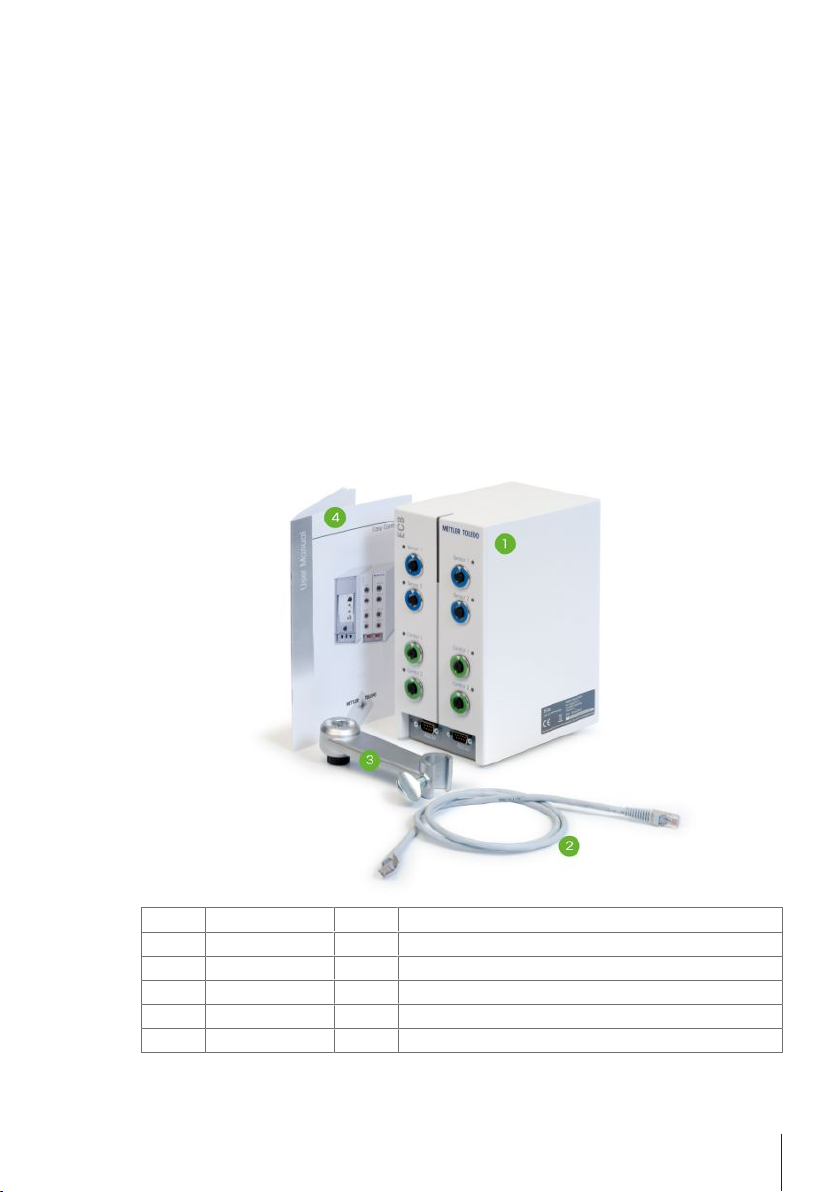
1.1 Scope of delivery
The following items are included in the ECB set (Order number: 30212440)
Number Order Number Amount Designation
1 30303439 1 ECB
2 51191988 1 CAN cable 1m
3 30281496 1 Lab Bar Holder
4 30251384 1 User Manual
30034475 2 Blank SevenExellence™ module
If an item is missing, please contact your local support.
Introduction 3ECB
Page 6

1.2 Check on arrival
Check the following things once the package has arrived:
• The package is in good condition.
• The content shows no signs of damage (e.g. broken covers, scratches etc.)
• The content is complete (see Scope of delivery).
If one condition is not fulfilled, please contact your local support.
Introduction4 ECB
Page 7

2 Safety Information
The ECB has been tested for the applications and intended purposes documented in this operating
instructions. However, this does not absolve you from the responsibility of performing your own tests
of the product supplied by METTLER TOLEDO regarding its suitability for the methods and purposes
you intend to use it for. You should therefore observe the safety measures for your protection and for
operation.
2.1 Definition of signal warnings and symbols
Safety notes are marked with signal words and warning symbols. These show safety issues and
warnings. Ignoring the safety notes may lead to personal injury, damage to the instrument,
malfunctions and false results.
Signal words
DANGER
WARNING
CAUTION
NOTICE
Note
Meaning of safety symbols
General hazard Notice Explosion
for an imminent danger with high risk, resulting in severe injuries or death
if not avoided.
for a hazardous situation with medium risk, possibly resulting in severe
injuries or death if not avoided.
for a hazardous situation with low risk, resulting minor or medium injuries
if not avoided.
for a hazardous situation with low risk, resulting in damage to the device
or the property or in loss of data.
(no symbol)
for useful information about the product.
2.2 Intended use
The ECB is a control box which is used together with a METTLER TOLEDO thermostat. It supports
analog third-party sensors and enables volumetric and gravimetric dosing.
Always operate and use your device in accordance with the instructions contained in this manual. Do
only use it together with equipment specified in this documentation.
Any other type of use and operation beyond the limits of technical specifications without the written
consent from Mettler-Toledo GmbH, is considered as not intended.
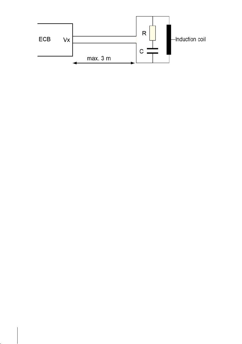
2.3 Product specific safety
WARNING
Control of valves
Implement suitable measures if you use valves which are not supplied by METTLER
TOLEDO! If electromagnets are attached, the output circuits of the valve outputs can start
to oscillate. The valves then remain open which could lead to a hazardous situation
with certain applications.
− Do connect a resistor-capacitor element next to the valve.
ð Use the schematics below on how to connect a resistor-capacitor element (RC
element).
Safety Information 5ECB
Page 8
Operational safety
For every instrument configuration used, you are responsible for ensuring that the entire system is
safe if a power failure occurs and that the reaction currently in progress cannot get out of control.
Site requirements
The instrument has been developed for indoor operation in a well-ventilated area. Avoid the following
environmental influences:
• Conditions outside of the ambient conditions specified in the technical data
• Powerful vibrations
• Direct sunlight
• Corrosive gas atmosphere
• Explosive atmosphere of gases, steam, fog, dust and flammable dust
• Powerful electric or magnetic fields
Note Gas Emission
The product does not emit any gases that could harm a person or damage the product.
Safety Information6 ECB
Page 9
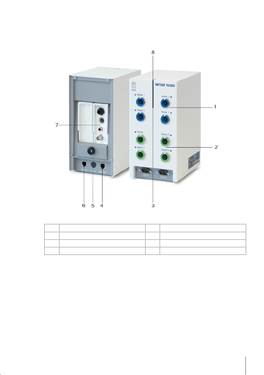
3 Overview
1 4x SmartConnect Sensor Ports 2 4x SmartConnect Control Ports
3 2x RS232 for METTLER TOLEDO balances 4 CAN Bus OUT
5 Port for optional AC power adapter 6 CAN Bus IN
7 Slot for SevenExcellence™ pH modules 8 Statuslight™
Overview 7ECB
Page 10

4 Mount ECB on Lab Bar
This step is optional you can also place the ECB on any even surface.
1 Screw the lab bar holder to the lab bar.
2 Screw the ECB onto the lab bar holder.
Mount ECB on Lab Bar8 ECB
Page 11

5 Set up ECB
Connect to main device
− Connect the CAN cable to the CAN IN port of the
ECB and connect the other end of the cable to a
main device or any other CAN device connected
to a main device.
Connecting AC power adapter to the ECB
A message is shown on the touchscreen in case the connected CAN devices require more power than
provided by the main device.
Proceed as follows to connect the AC power adapter to the ECB.
1 Connect the AC power adapter to the ECB on the rear.
2 Make sure the arrow on the plug is facing upwards.
3 Connect the country-specific plug to the mains.
See [Disconnecting the AC power adapter}21] for proper disconnection.
Download Firmware
The firmware is automatically transmitted from the main device to the ECB. The ECB Statuslight is
white during this transmission.
See also
2 Disconnecting the AC power adapter [}21]
Set up ECB 9ECB
Page 12

6 EasyMax port assignment
Right ports assigned
to reactor 2
Left ports assigned
to reactor 1
For the EasyMax the ECB is divided. This happens automatically when you connect it to the EasyMax.
EasyMax port assignment10 ECB
Page 13

7 SmartConnect Sensor ports
The sensor ports are used to connect third-party analog sensors to the ECB. The ECB has four sensor
ports. The following signals can be read by the ECB:
• Temperature (Pt100)
• Current (mA)
• Voltage (V)
Ready-to-use cables are available. Technical aspects such as configuration and soldering of the
cables are described in the SmartConnect Cables User Manual (30260711).
Available SmartConnect sensor cables
Order No. Product Description Supported signal types
30267163 SmartConnect Pt100 cable with loose ends Pt100
30267165 SmartConnect generic sensor cable with loose ends Pt100, Current, Voltage
30254779 SmartConnect LEO3 / EV-120 pressure sensor cable Pressure via Current
WARNING
Default data for Leo3 / EV-120 cable (order no.: 30254779)
The default data for LEO or EV-120 cable is based on a 300 bar sensor. Reconfigure
your cable if needed, see [Adjust pressure sensors}11].
1 If you use a pressure sensor with different limits, please reconfigure your cable
according to the pressure range.
2 Check if the value on the touchscreen and the sensor are the same, if not recon-
figure the cable.
7.1 Connecting cable to SmartConnect port
Note: There are dedicated ports for sensors (blue) and final control elements (green). Make sure the
color of the cable plug corresponds with the color of the port.
1 To fit the plug into the socket, the arrow on the plug needs to be at the top.
2 The status LED (only available on ECB) turns green once the sensor or final control element is
ready to use.
7.2 Adjust pressure sensors
The default values for pressure sensors are based on a 300 bar sensor. This means connecting a
LEO3, 300 bar will not need any adjustment. For other sensors do the following:
§ Sensor must be connected to cable that will be configured.
1 Tap on main screen.
SmartConnect Sensor ports 11ECB
Page 14

2 Tap on *ECB.
3 Tap on the SmartConnect sensor port where the pressure sensor is connected.
4 Tap on Adjust sensor to reconfigure your pressure sensor.
5 For the Measured Value enter the lower limit of the measuring range (current) e.g. 4.00 mA. For
the Reference Value enter the pressure value that corresponds with the lower limit e.g. 0.00 bar.
6 Tap Next.
7 For the Measured Value enter the upper limit of the measuring range (current) e.g. 20.00 mA.
For the Reference Value enter the pressure value that corresponds with the upper limit e.g. 4.00
bar.
8 Tap Apply to save the data.
ð The pressure value is now visible on the touchscreen.
SmartConnect Sensor ports12 ECB
Page 15

8 pH Module
Mount the pH Module
It is possible to use SevenExcellence™ pH/mV module (30034472) or SevenExcellence™ pH/Ion
(30034471). The modules must be ordered separately. ECB is delivered with two blank modules.
Note: Only analog pH electrodes can be connected.
To install the SevenExcellence™ pH modules proceed as follows:
§ Make sure the ECB is not powered at the time a
SevenExcellence pH module is added or
removed.
1 Loosen the screw on the plate on the rear of the
ECB until you can slide down the plate.
2 Remove the blank module.
3 Insert the SevenExcellence™ pH/mV or Seven-
Excellence™ pH/Ion module.
4 Slide the plate up and tighten the screw on the
plate back .
5 Switch the main device back on.
ð The ECB can now measure pH. NOTICEA pH
value is displayed even if no pH probe is
connected.
Adjust a pH sensor
pH sensors connected to the ECB can be adjusted with a 2-point adjustment.
§ 2 Buffer solutions at room temperature (25°C) are needed: Choose the pH range according to
your experiment.
1 Tap on pH on the main screen.
pH Module 13ECB
Page 16

2 Tap on Adjust sensor.
3 Place the probe into the first buffer solution with the low pH.
4 Confirm the message on the touchscreen by tapping ok.
5 If necessary correct the Buffer solution pH value so it corresponds to the value of the buffer
solution the sensor is in.
6 Wait until the value Measured pH is stable and tap Apply.
7 Take out the pH sensor from the first buffer solution and clean the sensor carefully.
8 Place the sensor into the second buffer solution with the higher pH.
9 Confirm the message on the touchscreen by tapping ok.
10 If necessary correct Buffer solution pH value so it corresponds to the value of the buffer solution
the sensor is in.
11 Wait until the value Measured pH is stable and tap Apply.
ð The 2-point adjustment is finished.
Measure pH with the main device
Note Temperature compensation for pH is per default done with Tr. If there is no Tr available, Tj will
be used. Values from temperature probes integrated into the pH sensor are not considered for the
calculation of pH.
− Connect an analog pH sensor to the BNC port of the SevenExcellence™ pH module.
ð pH is displayed on the touchscreen of the connected main device.
pH Module14 ECB
Page 17

9 Gravimetric Dosing
Gravimetric dosing refers to a technique where the dosing pump is controlled based on a balance
signal. The amount to be dosed can be specified in grams.
Supported pumps for gravimetric dosing
Support for any third-party dosing pump with analog control interface for:
• Current (0…20 mA)
• Voltage (-10…10 V)
• Frequency (0…3 Hz)
• Pulse width modulation (24 V)
For some dosing pumps there are ready-to-use cables. Others have to use the SmartConnect control
cable with loose ends. See list below:
NOTICE
Use of SmartConnect cables with Watson-Marlow 120U
Watson-Marlow 120U peristaltic pumps are not protected against ground loops.
− Do NOT use a SmartConnect control cable with loose ends (order no.: 30267164).
Order the specific control cable for Watson-Marlow 120U (order no.: 30254806),
which has a built-in galvanic isolation
Order No. Designation
30267164 SmartConnect control cable with loose ends
30254805 SmartConnect KNF SIMDos control cable
30254804 SmartConnect ProMinent control cable
30254806 SmartConnect WatsonMarlow control cable
Technical aspects such as configuration and soldering of the cables are described in the SmartConnect Cables User Manual (30260711).
Set up for gravimetric Dosing
Note: Control cable and the RS232 cable have to be connected on the same side of the ECB,
otherwise the dosing will not work.
§ A supported pump is available.
§ A METTLER TOLEDO balance is available.
§ ECB is connected to the main device.
1 Connect the pump to a control port on the ECB with a suitable SmartConnect control cable.
NOTICEIf you have a Watson-Marlow pump, make sure the pump is turned off when
connecting the cable.
2 Connect the balance to the RS232 port.
3 Configure the balance according to the specifications in [Set up configuration settings on
METTLER TOLEDO balances}17].
Gravimetric Dosing 15ECB
Page 18

4 Put the substance to be dosed on the balance and connect the tube to the pump.
SmartConnect control cable
for dosing pump
RS232 cable for
balance
Pump
with analog
signal
ð The ECB is now ready to do gravimetric dosing.
RS232
For METTLER TOLEDO balances
METTLER TOLEDO balances with MT-SICS protocol
interface. See [Set up configuration settings on
METTLER TOLEDO balances}17] for the communication settings to be set on the balance.
Gravimetric dosing on the thermostat
§ A supported pump and balance is connected.
1 Tap Dosing on the main screen.
ð All connected Dosing Units and ECBs are displayed.
2 Select the dosing device that you have prepared.
3 Tap and hold Prime tubes to fill the tubes.
ð The pump is dosing with 50 % of maximum dosing rate.
4 Tap Dosing of Substance 1 to enter the name of the chemical that is dosed.
5 Enter the Amount and Duration or Rate according to your experiment setting.
6 You can activate Hold dosing if to pause the dosing once the defined Tr value is exceeded.
ð The dosing will automatically continue once Tr falls below the defined threshold.
7 Tap Start to start the dosing.
ð The dosing starts immediately.
Gravimetric Dosing16 ECB
Page 19

9.1 Set up configuration settings on METTLER TOLEDO balances
Please refer to the Operating Instructions of the balances on how to change these settings.
Balance type Parameters
Excellence Series XA / XS / XP/ XPE • Host = RS232 built-in
• Baud rate = 9600
• Bit/Parity = 8/No
• Stop bit = 1
• Handshake = Xon / Xoff
• End of Line = <CR><LF>
• Character set = ANSI/Win
• Continous mode = off
MS / ML • RS232 = Host / SEND.OFF
• Baudrate = 9600
• Bit/Par. = 8/No
• HD.Shake = XON / XOFF
• RS E.O.L. = <CR><LF>
• RS Char = ANSI/WIN
• USB = SEND.OFF
PL-S • Function = F none
• Weighing mode = Std
• Weighing unit1/2: mg, g, or kg
• Autozero = no A.Zero
• Auto shut off = A.OFF –
• Peripheral unit = HoSt
• Send mode = S. oFF
• Send format = S.SICS
• Baud rate = bd 9600
• Bit / Parity = 8b-no
• Handshake = HS Soft
Gravimetric Dosing 17ECB
Page 20

PB-S/FACT, PB-L • Adjustment = CAL int (PB-S only)
• FACT = FACt oFF (PB-S only)
• Function = F none
• Weighing mode = Std
• Weighing unit1/2: mg, g, or kg
• Autozero = no A2Zero
• Peripheral unit = HoSt
• Send format = SICS
• Send mode = S. oFF
• Baud rate = bd 9600
• Bit / Parity = 8b-no
• Handshake = HS Soft
PB-G • Adjusment = oFF
• Function = F none
• Vibration adapter = 2
• Weighing proc. ad.: 2
• Repeatability = Good
• Weighing unit1/2: mg, g, or kg
• Autozero = AZ.oFF
• Autom. Shutdown = A.oFF –
• Power up mode = 9z.StArt
• Icons = on
• Peripheral unit = HoSt
• Data transfer mode = S. oFF
• Baud rate = bd 9600
• Bit / Parity = 8b-no
• Handshake = HS Soft
• Settings = List
Gravimetric Dosing18 ECB
Page 21

10 Volumetric Dosing
RS232 cable for syringe
pumps
Volumetric dosing refers to a technique where a syringe pump is used. The amount to be dosed can
be specified in milliliters.
Supported pumps for volumetric dosing
Support for selected KDS/Harvard syringe pumps with 9 or 15 pin TTL interface.
For some syringe pumps there are ready-to-use cables. See list below:
Order No. Designation
30254800 SmartConnect KDS/Harvard TTL cable (15 pin)
30254801 SmartConnect KDS/Harvard TTL cable (Legacy 9 pin)
Set up for volumetric Dosing
If only one dosing is connected to the main device it will be displayed automatically.
§ A supported syringe pump is available and prepared.
§ ECB is connected to main device.
− Connect the pump to a control port on the ECB with a control cable.
ð The dosing is now available on the touchscreen of the main device.
Volumetric dosing on the main device
Note: Syringe pumps are controlled through a so-called TTL (Transistor to Transistor Logic). The ECB
can only trigger the start and stop of a pre-programmed ramp on the syringe pump. The dosing is
controlled by the syringe pump. To capture the dosed amount you have to enter the same rate on the
ECB (see step 3). The captured amount may not be fully accurate so if necessary correct it in the
experiment data in iControl.
§ A supported and pre-programmed syringe pump is connected.
1 Tap Dosing on the main screen.
ð All connected Dosing Units and the ECB are displayed.
2 Select the syringe pump that you have prepared.
Volumetric Dosing 19ECB
Page 22

3 Optionally enter the Rate to capture the dosed amount. Enter the same dosing rate as pre-
programmed on the syringe pump.
4 Tap Start to start the dosing.
ð The dosing starts immediately.
Volumetric Dosing20 ECB
Page 23

11 Maintenance
11.1 Cleaning and Decontaminating
Clean the outside of the housing with a cloth moistened with ethanol.
The device can only be cleaned on the outside. In case chemicals contaminate the inside of the box,
the box has to be disposed.
11.2 Calibration and Adjustment
Keep in mind that the ports of your device need regular calibration and adjustment to generate the
most accurate data. Please contact a Field Service Engineer to perform a calibration and an
adjustment.
11.3 Disconnecting the AC power adapter
NOTICE
Do not disconnect the cables by pulling on the cable
This could damage the connectors. Only pull out the cable at the end using the plug.
To disconnect the AC power adapter proceed as follows:
§ The main device is turned off.
1 Pull back the movable part of the plug.
2 Use gentle force to disconnect the AC power adapter from the device.
11.4 Disposal
In conformance with the European Directive 2002/96/EC on Waste Electrical and
Electronic Equipment (WEEE) this device may not be disposed of in domestic waste. This
also applies to countries outside the EU, per their specific requirements.
Please dispose of this product in accordance with local regulations at the collecting point
specified for electrical and electronic equipment. If you have any questions, please contact
the responsible authority or the distributor from which you purchased this device. Should
this device be passed on to other parties (for private or professional use), the content of
this regulation must also be related.
Thank you for your contribution to environmental protection.
Maintenance 21ECB
Page 24

12 Technical data
12.1 General
AC power adapter rating
(optional)
Instrument rating
Dimensions (WxDxH)
Weight
Number of ECBs connected to one main device
Humidity
Altitude
Overvoltage category
Pollution degree
Ambient temperature
Usage
Line voltage 100…240 VAC
Input frequency 50/60 Hz
Input current 1.8 A
Output voltage 24 VDC
Output current 5 A
Mains supply voltage fluctuations Up to ± 10 % of the nominal
voltage
Input voltage 24 VDC supplied via CAN Bus
Max. power 120 W
110 mm x 152 mm x 215 mm (4.33” x 5.98” x
8.47”)
2.5 kg
Max. 1
Max. relative humidity 80 % for temperatures up to
31°C decreasing linearly to 50 % relative humidity
at 40°C
Up to 2000 m
II
2
5 °C…40 °C
For indoor use only
12.2 Interface specifications
SmartConnect
Sensor port
(4x)
Technical data22 ECB
Signal Measuring
Pt100
(Temperature)
Current (mA) 0/4…20mA
Voltage (V) ±10V over
Range
-120…400 °C 0.01K -50…300 °C:
with 100Ω
impedance
1GΩ
Resolution Accuracy Supports
4 or 2-wire
±0.2 K
0.002 mA 0.005 mA Any sensor /
0.001 V 0.005 V Any sensor /
temperature
sensors
transmitter with
Current (mA)
output
transmitter with
Voltage (V)
output
Page 25

SmartConnect
Control Port
Signal Control Range Resolution Accuracy Supports
Current (mA) 0/4…20 mA with
(4x)
Voltage (V) 0…10V with
PWM (Pulse
width
modulation)
Frequency 0…3Hz with
TTL (Transistor
to transistor
logic) In/Out
pH Module
Port Measuring
(2x)
BNC 0…14 pH 0.001 ±0.05 Analog
RS232
For METTLER TOLEDO balances
max 500Ω
0.005 mA 0.01 mA Dosing pumps
0.0025 V 0.01 V Dosing pumps
I
= 10mA
max
0…100% of one
0.01 s 0.02 s Dosing valves
second 24V with
33Ω min.
(I
=0.7 A)
max
0.008 Hz 0.008 Hz Dosing pumps
20ms pulse with
20mA max load
Triggering start of preprogrammed
dosing ramp
Resolution Accuracy Supports
Range
METTLER TOLEDO balances with MT-SICS protocol
interface. See [Set up configuration settings on
METTLER TOLEDO balances}17] for the communication settings to be set on the balance.
n/a Syringe pumps
electrodes
Technical data 23ECB
Page 26

13 CE Certification
METTLER
TOLEDO
®>
EU
Declaration
of
Conformity / EU-Konformitätserklärung / OV
Declaration
de
conformite
europeenne
/
CfC>
Declaraciön
de
conformidad UE
/
;
JÜ
Certificazione
di
conformitä
UE
/
0®
EC
AeiuiapauMH
3a
ctoTBeTCTBHe / ®
EU
Prohläseni o shode
/ ;M>
EU-overensstemmelseserklaering
/
OD
ArjAuior)
auuu6p<pu)ar|q
E.E. / O0
ELi
vastavusdeklaratsioon / OD EU-
vaatimustenmukaisuusvakuutus / Dearbhü Comhreireachta
AE / 'Ä-
EU
izjava o sukladnosti
/
<b§>
EU
Megfelelösegi
nyilatkozat
/
Q\)
EU
JS^a!" / <&>
EU
»fj-'g I C-t)
ES
atitikties
deklaracija / 0£>
ES
atbilstibas deklaräcija
/ (®
Dikjarazzjoni
ta'
Konformitä
tal-UE / 0®
EU-
conformiteitsverklaring
/ 00
Deklaracja
zgodnosci
UE / 00
Declaracäo
de
Conformidade
da
UE
/
<M>
Declaratje
de
conformitate
UE
/ !3©>
fleK/iapaMMH o cooTBeTCTBMM
Tpe6oBaHHHM
EC / 0*0
EÜ
Vyhläsenie o zhode / 00
Izjava o skladnosti
EU / 00
EU-försäkran
om
överensstämmelse / ®
ianSn^ua^nn'5iJäijfiPi'i»jjj'iPi'5§nuJlMfinv(^T,3iJ
(Declaration
of
Conformity) / EU
—
ProdllCt
/
Produkt / Produit /
Producta / Prodotto / rtpoflynT/
Vyrobek / Produkt /
npolöv/
Toode
/Tuote
/Täirge /
Proizvod / Termek / HA£ / 7
Gamlnys / Izsträdajums / Prodott / Product / Produkt / Produto / Produs
/
npoflyKiiMsi / Produkt / l/delek / Produkt / rutfiii
/
Control
Unit
Easy
Control Box (ECB)
Manufactltrer
/
Hersteller /
Fabricant / Fabricante
/ Produttore /
npon3BO/inren / Vyrobce / Producent
/
KaraoKEuaoTri?/
Tootja / Valmistaja/
Deantiisöir / Proizvodac / Gyärtö / Ii— 1
afläi'äs]
/Gamintojas ; Raiots
js
/
Manrfattur/
Producent / Producent / Fabricante / Producätor/ npon3BOAnrejib /Vyrobca / Proizvajalec
/THIverkare
/
fjuSst
/
WäfiiS
Mettler-Toledo
GmbH
Im
Langacher 44
8606
Greifensee
SWITZERLAND
This
declaration of
conformity
is
issued
underthe
sole
responsibility of the manufacturer.
/
Die alleinige Verantwortung
für
die Ausstellung dieser
Konformitätserkiärung
trägt der Hersteller. / La presente declaration
de
conformite est etablie
sous
la seule responsabilite du fabricant.
/
La
presente declaraciön
de
conformidad se expide
bajo
la
exciusiva responsabilidad
del
fabricante. / La presente certificazione
di
conformitä e rilasciata
sotto
la
responsabilitä
esclusiva
del produttore. / HacTomuaTa
neKnapauufi
3a
cbOTBeTCTBHe e H3/ia,neHa
no/i
e/iMHCTBeHaxa
OTTOBOPHOCT
Ha
npon3BOflMTenR. / Toto
prohläseni 0 shode
vydava vyrobce na svou
vlastni
odpovednost. / Producenten
er
eneansvarlig
for
udstedelsen
af
denne
overensstemmelseserklaering. / H
Trapoüoa öhAiuan auppöp<pü)or|? EKÖförrai
pE
omoicAeiOTiKr)
cuBuvrj
TOU
KQTO.cnccUQOTr|. / See vastavusdeklaratsioon
on
väljastatud
tootja
ainuvastutusel.
/
Vaatimustenmukaisuusvakuutus
on annettu valmistajan yksinomaisella vastuulla. / Is
faoi
fhreagracht an
deantüsöra
amhäin a eisitear an dearbhü comhreireachta
seo. / Ova
Izjava o sukladnosti
izdaje
se pod
punom
odgovomoscu
proizvodaöa. / Az
aläbbi
megfelelösegi
nyilatkozat
kiadäsäert
kizärölag a gyärtö
feielös. / ZOMfS
Ä*»li/-A-©IMtt*ffl=fcL^TftfT**l*'f.
/ol 05
*A^o\o\\
^IStlsisLlcK/SiatitiktiesdeklaracijaiSduotatikgamintojo
atsakomybe. / 51
atbilstibas
deklaräcija
ir
izdota
vienigi
uz
razotäja
atbildlbu. / Din
id-dikjarazzjoni
ta'
konformitä
hi
man
rüg a taftt
ir-responsabbilta
unika
tal-
manifattur. / Deze
conformiteitsverklaring
wordt
verstrekt onder de exciusieve verantwoordelijkheid van
de
producent. / Ta deklaracja zgodnosci
zostaJa
wystawiona
na
wytaczna.
odpowiedzialnosc producenta. / Esta
deciaragao
de
conformidade e emitida sob a responsabilidade exciusiva
do
fabricante. / Prezenta
decfara(ie
de
conformitate
este
emisa*
pe
räspunderea exclusivä a produeätorului. / HaciOKmaH
AeruiapauHH c COOTBCTCTBHM
Bbiiiymena
IIOA
MCKJirOHHrejibnyto
oiBeiciBennoc
ib
npon3Bo/inTenp!. / Toto vyhläsenie o zhode vydäva vyrobca
na
vlastnü zodpovednosf.
/2a
izdajo
te
izjave o skladnosti
je
odgovoren
izkljucno
proizvajalec. / Denna
försäkran
om överensstämmelse utfärdas
pä
tillverkarens eget ansvar. / iöntfnwdfwmidÖuÄfnujn«isiu&
/
jRfej*^
The
object
of
the declaration described above
is in
conformity
with
the
following
European directives and
Standards
or
normative
documents:
/
Der oben
beschriebene
Gegenstand
der Erklärung erfüllt die Vorschriften der folgenden europäischen
Richtlinien
und
Normen
oder normativen Dokumente: / L'objet
de la
declaration decrit
ci-dessus
est en conformite
avec
les
directives
et
normes
europeennes
suivantes
et
autres documents ä vocation normative : /
El objeto
de la
declaraciön descrita
ante
norm
ente se ajusta a lo
establecido
en
las siguientes directivas,
normas y documentos normatives europcos:
/L'oggetto
della dichiarazione
di
cui
sopra e conforme a direttive, norme o Standard europei
di
seguito: / npe^rvierbT
na
AeKJiapauiiHia.
oinican
110-iope, e B
cto
laeic
IBUC
ebe
cjiejinme
eßpoueriCKH
^petoMBM M crait^aprn
wwi
noprvia
IHBHM
AOKyMetuK: / VySe popsany
predmöt
prohläseni
je v souladu s näsledujtcimi
evropskymi
smemicemi a normami
nebo normativnimi
dokumenty: / Genstanden
for
erkiaeringen,
som
beskrevet ovenfor,
er
i
overensstemmelse
med folgende
europasiske
direktiver
og
standarder eller normative
dokumenler: / To
avTiKEfpEvo
Jt\<;
örjAwanc.
wo« TrcpiYpÖ9£Tai napoTTtivui
ouppoptpüvETai
pe
Tic,
napaKÖTUJ
EupconaiKEC,
oönY'EC.
tai
npöTinra
i*j
KavovioriKä
tyypaya: I Ülafkirjeldatud
deklareerilav
toode on kooskölas
järgmiste
Euroopa
direktiivide
ja
standardile
vöi
normdokumentidega: / Yllä määritetyn
vakuutuksen
tavoite
noudattaa seuraavien eurooppalaisten
direktiivien,
normien
tai
normatüvisten
asiakirjojen vaatimuksia: / Ta
euspeir
an dearbhaithe a dtugtar
cur-sios
air thuas
de
reir na dtreoracha agus
na
gcaighdeän Eorpach
rjö
de
reir
na
ndoieimead
normatach
Eorpach seo a leanas: / Predmet
izjave naveden iznad u skladu
je
sa
sljedeeim
europskim
dlrektivama i normama
normativnih
dokumenata:
/
A
fent
emlitett
nyilatkozat tärgya
megfelei
az
aläbbi euröpai iränyelveknek,
szabvänyoknak,
illetve normativ
dokumentumoknak:
/±.j&0!>md)§ftltt:«
ttSA^löLTÖ!)
R«Ä^teJ:tfa**4^tt«SÄ#(=aÄLTL^CÄ:tlt*-r*CfC-r:
o\ #<>i2.\
E^EI
5^
EE^
T?^
§AI§
^^sfb
cij
SisLlct- / Pirmiau
aprasytas
deklaracijos objektas atitinka
Sias
Europos direktyvas
ir
standartus
ar
norminius
dokumentus: / leprieks
aprakstltais
deklaräctjas
prieksmets
atbilst
tsiak
norädllajcm
Eiropas
direktiväm
un
standartiem
vai
norma'Tvajiem
dokumentiem: / L-ofigett
tad-dikjarazzjoni
deskritta hawn fuq
hu
konformi
mad-direttivi
Ewropej u l-istandards
jew
id-dokumenti
normattivi
Ii
gejjin: / Het
voorwerp van voornoemde verklaring
is in
overeenstemming
met
de
volgende
Europese
richtlijnen
en
normen
of
normatteve
docurnenten: / Tresi
powyzszej deklaracji jest zgodna z nast^puja.cymi
dyrektywami
europejskimi
oraz normami
lub
dokumentami
normalizuja.cymi: / O
objeto
da
deciaragao
aeima
mencionada
estä
em
conformidade com as seguintes diretrizes e normas europeias
ou
documentos
normativos: / Oblectul
declaratiei
descris
mai
sus este
In
conformitate cu urmätoarele directive
$i
standarde europene sau acte normative: / npe/iMST
/ieKnapannn,
onncaHHbin
Bbiiue,
cooiBeiciBye i cjieüyrotuMM
c-cponencKuri
iitipeKH'Bari n c
ian^f
piar.i
HJIM
uopMEi
I^BMUM
floKyMemaM: / Predmet
vySsie
uvedeneho vyhlasenia
o
zhode je v sülade s nasledujücimi
euröpskymi
smernicami a normami
alebo
normativnymi
dokumentmr: / redmet
zgoraj opisane izjave
je
skladen z naslednjimi
evropskimi
direktivami
in
Standard!
ali
normativnimi
dokumenti: / Föremälet för försäkran som beskrivs ovan överensstämmer med följande europeiska direktiv och
standarder
eller harmoniserade dokument: / ^^#^0*18^^
WoSuiuW
/
j-^
Page
1 of 3
13.1 ECB Declaration of conformity 20160006
CE Certification24 ECB
Page 27

EC - DECLARATION
OF CONFORMITY
KD
No.:
Document
No.: 20160006
The
undersigned,
representing
the
following
manufacturer
Mettler-Toledo
GmbH
Im
Langacher
44
8606
Greifensee, SWITZERLAND
herewith
declares that the product
Control
Unit
Easy
Control Box
(ECB)
For
additional types, see page Type code
certified
model:
is
in
conformity with
the
provisions
of
the following
EC
directives
(incl.
amendments)
2006/95/EC;
2014/35/EC
***)
Low voltage (LVD)
2004/108/EC;
2014/30/EC
***)
Electromagnetic compatibility
(EMC)
and
that the
Standards have been
applied. ***)
valid
after
20.04.2016
References
of
Standards
for
this declaration
of
"conformity,
or
parts thereof:
Harmonized
Standards
of
Europe and Switzerland:
Safety
Standards:
IEC/EN61010-1:2010
EMC
Standards
(*
Emission;
**
Immunity):
IEC61326-1:2012 / EN61326-1:2013
(class
B *)
IEC61326-1:2012 / EN61326-1:2013
(Industrial requirements
**)
Metrological
Standards:
IP
Standards:
Standards
for
Canada, USA and Australia:
Page
2 of 3
CE Certification 25ECB
Page 28

Mettler-Toledo GmbH
Im Langacher 44
8606 Greifensee, Switzerland
www.mt.com/contact
Subject to technical changes.
© Mettler-Toledo GmbH 08/2016
30251384A
www.mt.com/Autochem
For more information
*30251384*
 Loading...