

Page 1
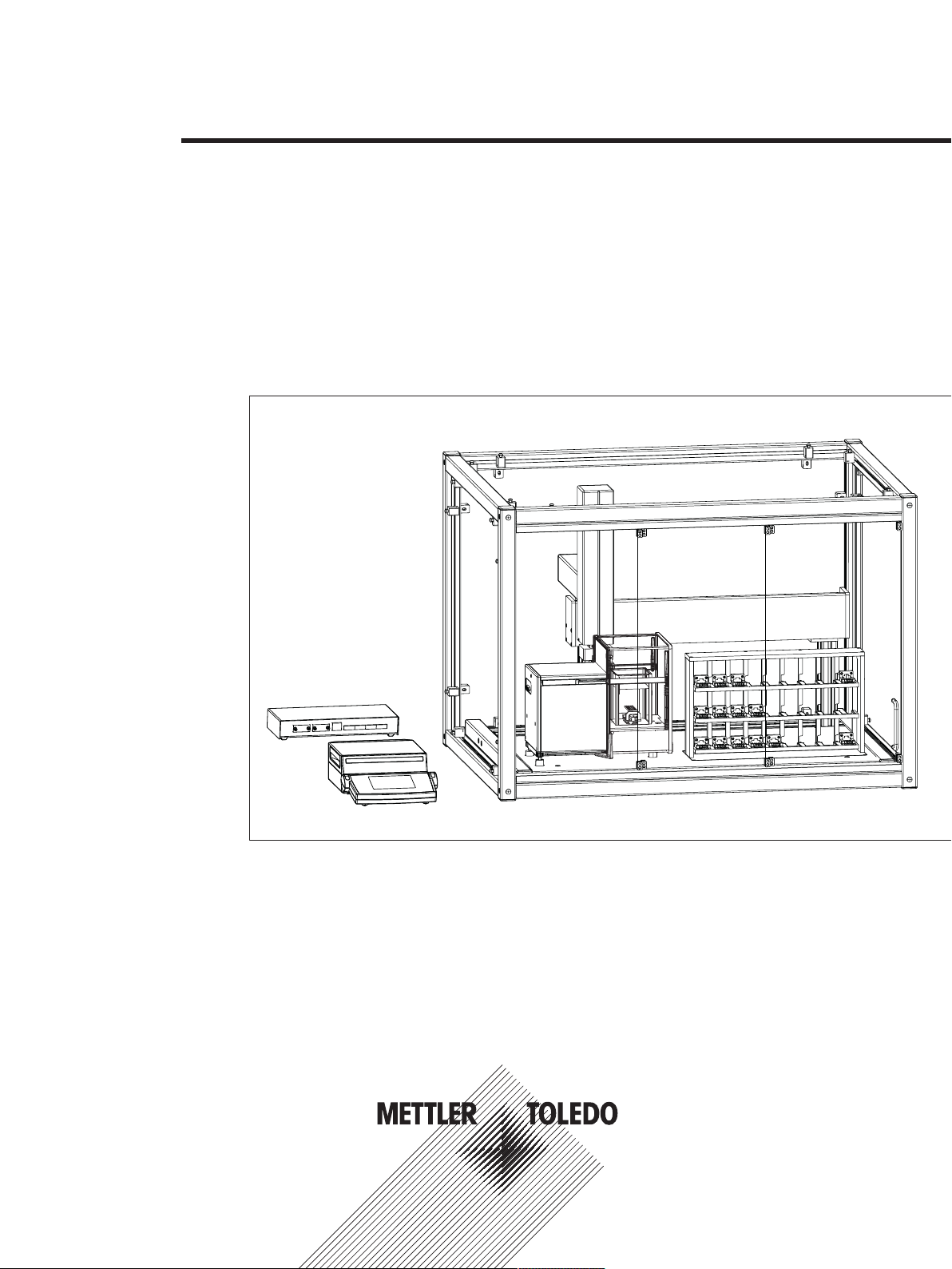
Robotic Mass Comparator
Reference Manual
e100
Page 2

Page 3

Table of Contents
1 Introduction 3
2 Safety Information 4
2.1 Definitions of signal warnings and warning symbols........................................................ 4
2.2 Product specific safety notes ......................................................................................... 4
2.3 Warning notices on the instrument................................................................................. 6
2.4 Stopping in case of emergency...................................................................................... 6
3 Design and Function 7
3.1 Overview instrument..................................................................................................... 7
3.2 Component descriptions ............................................................................................... 8
3.3 Wiring scheme ............................................................................................................ 12
3.4 Safety devices ............................................................................................................. 13
3.5 Status indication light................................................................................................... 13
4 Installation and Putting into Operation 14
4.1 Selecting the location ................................................................................................... 14
4.2 Scope of delivery ......................................................................................................... 14
4.3 Assembling the instrument............................................................................................ 15
4.4 Connecting and setting up the instrument ....................................................................... 15
4.5 Preparing the weight magazine ..................................................................................... 17
3.2.1 Overview AX106 balance ............................................................................... 8
3.2.2 Overview balance control unit......................................................................... 9
3.2.3 Overviw robot system .................................................................................... 10
3.2.4 Overview type plate ....................................................................................... 11
3.2.5 Overview robot system control unit.................................................................. 11
3.2.6 Control software............................................................................................ 11
4.5.1 Selecting a suitable weight carrier ................................................................... 17
4.5.2 Loading the weight magazine......................................................................... 20
5 Operation 22
5.1 Starting e100control..................................................................................................... 22
5.2 Entering and editing the weights data............................................................................. 23
5.2.1 Standards data ............................................................................................. 23
5.2.2 Test weights data .......................................................................................... 26
5.3 Allocating the weight magazine places........................................................................... 27
5.4 Determining the weighing process settings and series scheme .......................................... 28
5.4.1 Weighing process settings ............................................................................. 29
5.4.2 Series scheme .............................................................................................. 31
5.4.2.1 Series scheme in mode 'One-vs.-one comparisons' .................................... 32
5.4.2.2 Series scheme in mode 'Down-/upward calibration' .................................... 34
5.5 Choosing the report contents......................................................................................... 36
5.6 Adapting system settings .............................................................................................. 36
5.7 Starting and monitoring the weighing process ................................................................. 37
5.7.1 Starting the weighing process ......................................................................... 37
5.7.2 Monitoring the weighing process..................................................................... 38
5.8 Analyzing measurement data and report......................................................................... 40
5.8.1 Measurement report....................................................................................... 40
5.8.2 Calculations ................................................................................................. 45
5.9 Adjusting the balance................................................................................................... 49
5.10 Measuring the corner load error..................................................................................... 49
5.11 Upgrading e100control................................................................................................. 52
5.12 Remote-controlling the e100comparator......................................................................... 53
5.12.1 Generating a file importable into e100control as settings file .............................. 53
5.12.2 Importing an externally defined settings file into e100control.............................. 56
Table of Contents 1Robotic Mass Comparator
Page 4

5.12.3 Communicating via the serial port................................................................... 58
5.13 Selecting the application mode...................................................................................... 60
5.13.1 Interface to ODBC climate data sources: Overview............................................. 61
5.13.2 Read data via ODBC from an Access database................................................. 62
5.13.3 Read data via ODBC from an Excel sheet......................................................... 63
5.13.4 Read data via ODBC from a .csv text file.......................................................... 65
5.13.5 Read data via ODBC from other database systems............................................ 66
5.14 Sending emails............................................................................................................ 66
5.15 Reduce pre-run/centering time using ‘Standard’s centering history’ .................................... 68
5.16 Transmit measurement report data to a TCP/IP server....................................................... 69
6 Maintenance 71
6.1 Maintenance table........................................................................................................ 71
6.2 Performing routine tests................................................................................................ 71
6.3 Maintaining robot system.............................................................................................. 71
6.4 Cleaning..................................................................................................................... 72
6.4.1 Cleaning agents............................................................................................ 72
6.4.2 Cleaning the components............................................................................... 73
7 Technical Data 75
7.1 General data ............................................................................................................... 75
7.2 Dimensions................................................................................................................. 77
8 Accessories 78
9 Disposal 81
Index 83
Table of Contents2 Robotic Mass Comparator
Page 5

1 Introduction
In purchasing this automated mass comparator, you have chosen a talented, highly professional weighing
machine. Combining METTLER TOLEDO's world-class weighing sensor technology and robotic expertise e100
comparator - automated 100 g mass comparator - sets new standards in the field of high-resolution weighing.
Performance and reliability on the one hand, productivity on the other are of concern to metrologists. These
aspects were given great attention throughout the development of the e100 comparator. This product offers
new ways with respect not only to direct comparison, but to down-/upward calibration as well. e100
comparator and its smart, versatile e100control software will become in no time indispensable to any mass
standards laboratory.
To ensure that we can offer you personal service and provide you with the most efficient support, this product is
accorded special treatment: not only the complete installation of the automated mass comparator, but also the
instruction are handled by a specialist from Mettler-Toledo GmbH, Greifensee (Switzerland) or by a specialist
from your country who has been specially trained.
Disclaimer for comparators
In this document "balance" is a terminology preamble and stands for comparators.
Due to the high resolutions and differential weighing application, comparators are tested with differential
measurement only. Therefore the specification values defined are to be tested with differential methods only.
Software version
This document refers to the initially installed software version V 4.95.
Finding more information
u http://www.mt.com/lab-robotic-MC
Search for documents u www.mt.com/library
For further questions, please contact your authorized METTLER TOLEDO dealer or service representative.
u www.mt.com/contact
Conventions and symbols
Key and/or button designations and display texts are shown in graphic or bold text (e.g.
Refers to an external document.
Note
For useful information about the product.
, OK).
Elements of instructions
Prerequisites
§
1 Steps
2 ...
ð Intermediate results
ð Results
Introduction 3Robotic Mass Comparator
Page 6
2 Safety Information
Two documents named "User Manual" and "Reference Manual" are available for this instrument.
• The User Manual is printed and delivered with the instrument.
• The electronic Reference Manual contains a full description of the instrument and its use.
• Keep both documents for future reference.
• Include both documents if you transfer the instrument to other parties.
Only use the instrument according to the User Manual and the Reference Manual. If you do not use the
instrument according to these documents or if the instrument is modified, the safety of the instrument may be
impaired and Mettler-Toledo GmbH assumes no liability.
2.1 Definitions of signal warnings and warning symbols
Safety notes contain important information on safety issues. Ignoring the safety notes may lead to personal
injury, damage to the instrument, malfunctions and false results. Safety notes are marked with the following
signal words and warning symbols:
Signal words
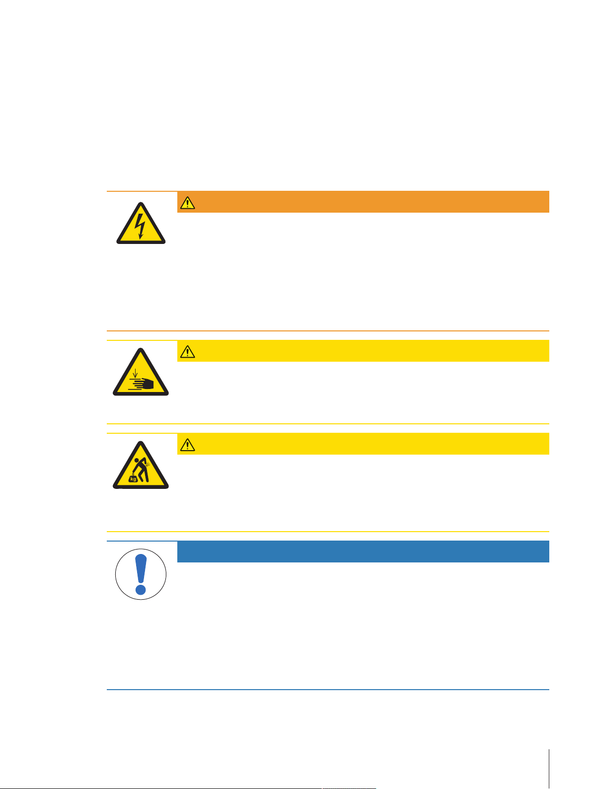
WARNING
A hazardous situation with medium risk, possibly resulting in death or severe injury if
not avoided.
CAUTION
NOTICE
A hazardous situation with low risk, resulting in minor or moderate injury if not avoided.
A hazardous situation with low risk, resulting in damage to the instrument, other
material damage, malfunctions and erroneous results, or loss of data.
Warning symbols
Electrical shock Heavy object Crushing hazard
General hazard: read the User Manual or the Reference Manual for information about the hazards
and the resulting measures.
Personal protective equipment
Chemical resistant safety gloves are intended to protect hands against aggressive chemicals.
The protective goggles protect the eyes from flying parts and liquid splashes.
2.2 Product specific safety notes
Intended use
This instrument is designed to be used in laboratories by trained staff. The automated mass comparator is
intended for measuring calibration weights using direct comparison or down-/upward calibration.
Any other type of use and operation beyond the limits of technical specifications without written consent from
Mettler-Toledo GmbH is considered as not intended.
Responsibilities of the instrument owner
The instrument owner is the person holding the legal title to the instrument and who uses the instrument or
authorizes any person to use it, or the person who is deemed by law to be the operator of the instrument. The
instrument owner is responsible for the safety of all users of the instrument and third parties.
Safety Information4 Robotic Mass Comparator
Page 7
METTLER TOLEDO assumes that the instrument owner trains users to safely use the instrument in their
workplace and deal with potential hazards. METTLER TOLEDO assumes that the instrument owner provides the
necessary protective gear.
Trained personnel
Persons performing weighing processes must fulfill the following basic knowledge requirements regarding the
handling of METTLER TOLEDO instruments and associated software:
• Are able to complete the tasks entrusted to them and independently detect and avoid any possible dangers.
• Have expertise and experience as well as their familiarity with all applicable regulations.
• Able to prove that they have undergone training.
Safety notes
WARNING
Death or serious injury due to electric shock
Contact with parts that carry a live current can lead to death or injury.
1 Only use the approved METTLER TOLEDO power supply cable and AC/DC adapter with a
current-limited SELV output.
2 Connect the power cable to a grounded power outlet, ensure correct polarity.
3 Keep all electrical cables and connections away from liquids and moisture.
4 Check the cables and power plug for damage and replace damaged cables and power
plugs.
CAUTION
Freely accessible parts, which can move automatically
Injuries due to crushing are possible when reaching into the working area of the robot arm
during adjustment procedures or during normal operation.
− Do not reach into the working area when the robot arm is moving.
CAUTION
Damage on instrument due to incorrect moving or unsuitable location site
Moving the instrument yourself might lead to injuries or might damage the instrument.
1 Contact a METTLER TOLEDO representative before changing the location of the instrument.
2 Do not carry the instrument yourself. It's total weight exceeds the acceptable limit in
accordance to the applicable regulations.
NOTICE
Damage due to inappropriate use
Inappropriate use of the instrument may lead to significant material damage.
1 Installation, adjustment and repair work shall be carried out exclusively by specialists
from METTLER TOLEDO. Never undertake any installation, adjustment or repair, unless
duly instructed by the above mentioned specialists.
2 Do not open the instrument, the control units or the robot system. They do not contain any
parts which can be maintained, repaired, or replaced by the user. If you ever have
problems with your instrument, contact your METTLER TOLEDO dealer.
3 Use only original parts supplied or approved by the manufacturer.
A listing of all parts can be found in the Reference Manual (RM).
Safety Information 5Robotic Mass Comparator
Page 8
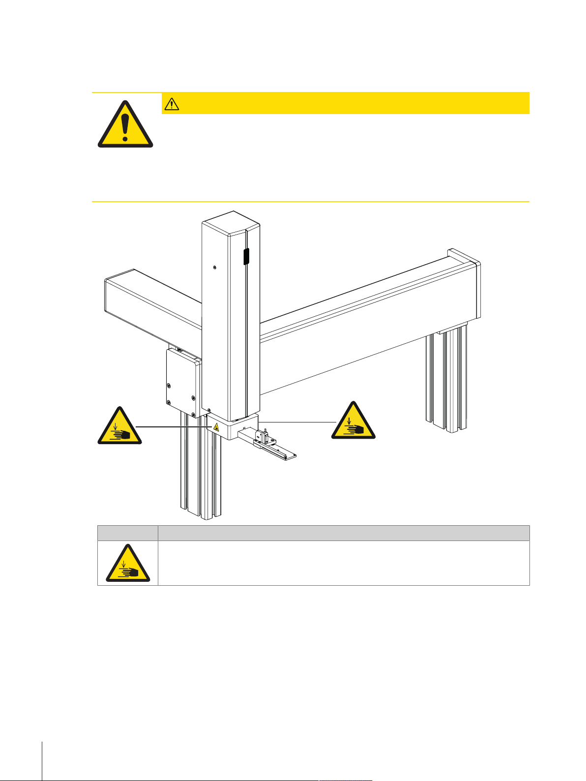
2.3 Warning notices on the instrument
The following symbols are attached to the instrument. They relate to the direct environment where they have
been put up.
CAUTION
Illegible signage
Stickers and signs can get dirty or become illegible. The risks can no longer be recognized
and necessary operating instructions can no longer be adhered to. This presents a risk of
injury.
1 Always keep safety, warning and operating notices in good legible condition.
2 Immediately replace damaged signs or stickers.
Symbol Meaning
Indicates the possibility of personal injury due to crushing when the robot hand is moving up
and down. Pay attention that the robot hand may move without any prior warning. Do not
reach into the working area when parts of the instrument are moving.
2.4 Stopping in case of emergency
To stop the instrument in case of an emergency, proceed as follows:
1 Switch off the power supply by pulling out the power plug.
2 Secure the instrument against switching on again.
3 Have fault repair performed by expert personnel or personnel of METTLER TOLEDO.
4 Before starting up again, check the instrument and make sure that there is no risk of danger.
Safety Information6 Robotic Mass Comparator
Page 9
3 Design and Function
1
2
6
7
45
3
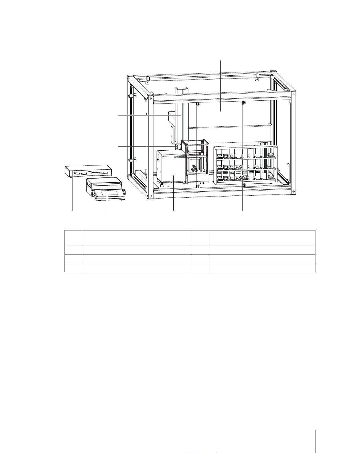
3.1 Overview instrument
Legend overview instrument
Weighing chamber accessible through sliding
1
door
Balance (AX106 mass comparator)
3
Robot system control unit
5
3-axis robot system
7
Weight magazine with 27 weight carriers
2
Balance control unit
4
Robot hand with light barrier
6
Design and Function 7Robotic Mass Comparator
Page 10
3.2 Component descriptions
2
1
3
8
6
4
5
7
9
10
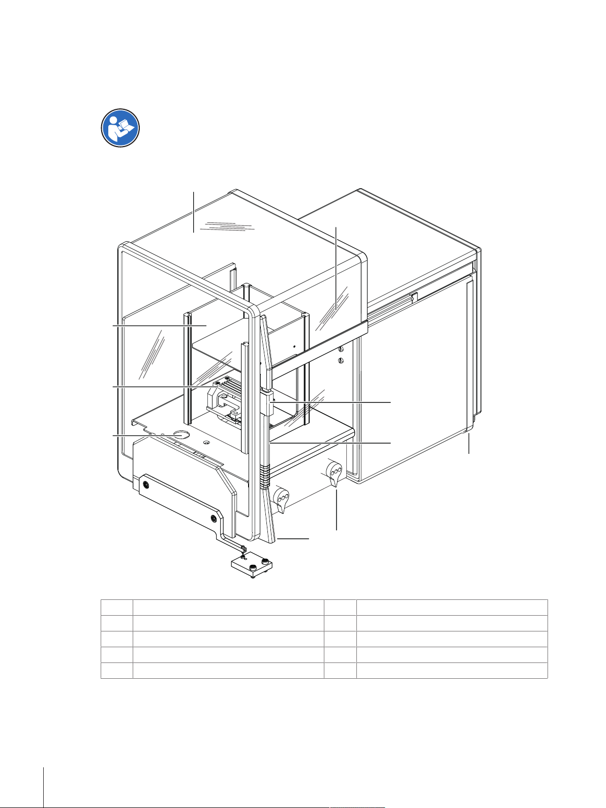
3.2.1 Overview AX106 balance
As balance the AX106 comparator is used.
For full information, always consult and download the Operating Instructions (OI).
u www.mt.com/ax-comparator-OI
Legend overview balance
Glass draft shield
1
Inner draft shield
3
Level indicator
5
Door handle
7
Door follower handle
9
Type name
2
Weighing pan
4
Door coupling element
6
Control knobs for dial weights
8
Leveling screw
10
Design and Function8 Robotic Mass Comparator
Page 11
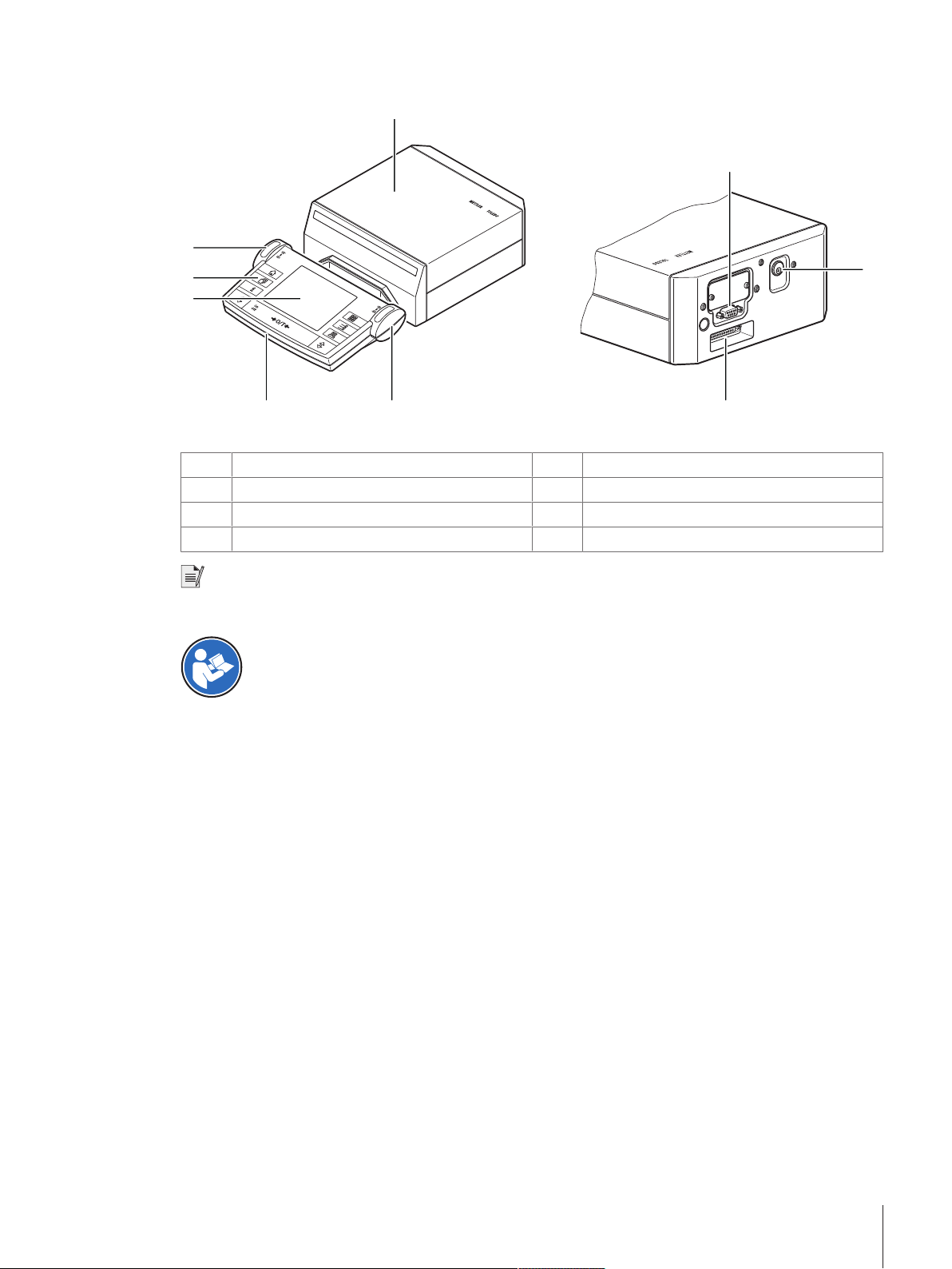
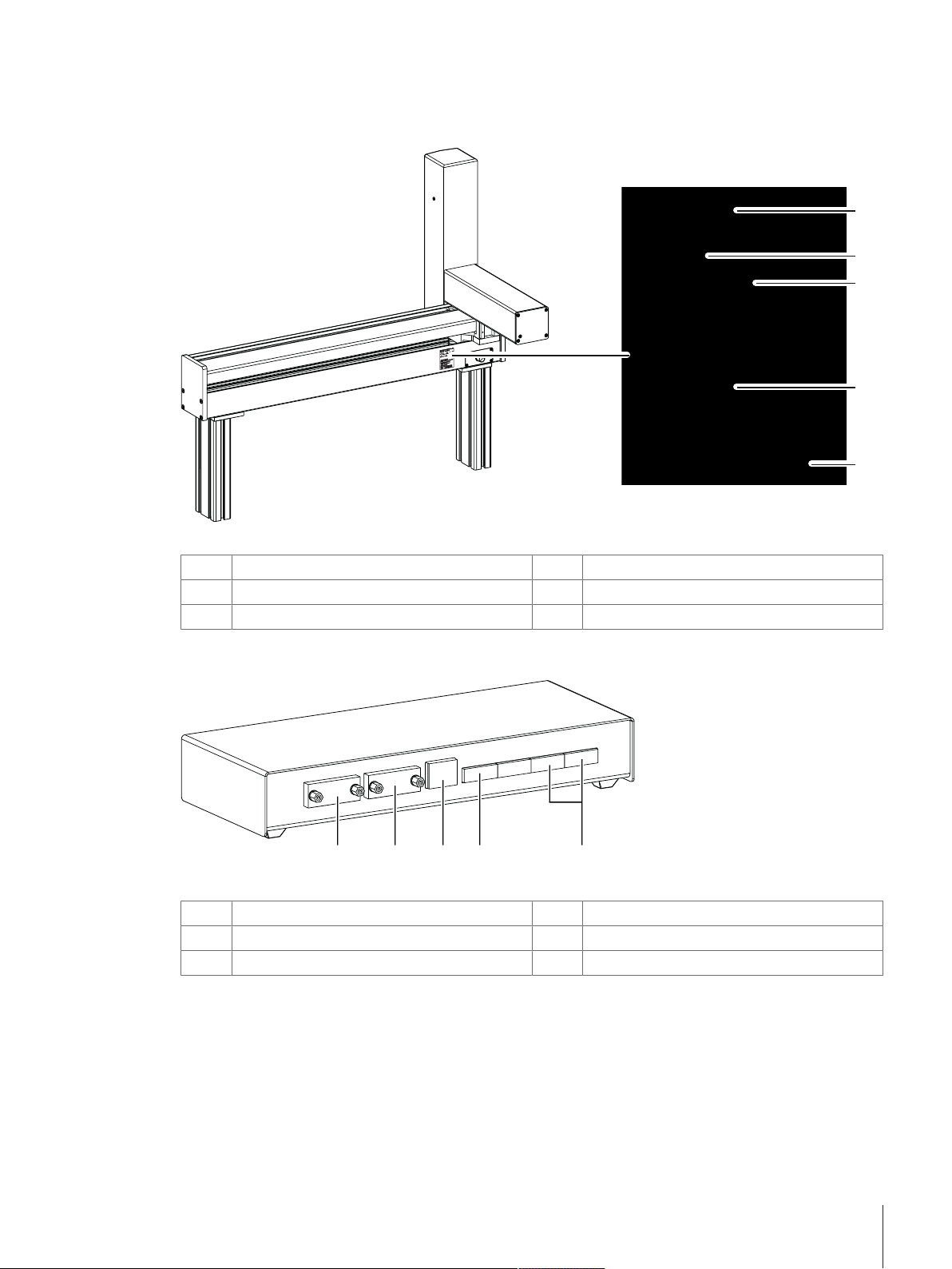
3.2.2 Overview balance control unit
For con
n
ectio
n
to
balan
c
e
onl
y
R
S
2
3
2C
Powe
r
s
u
p
p
l
y
2
5
4
1
3 2
6
7
8
Legend overview balance control unit
Balance control unit
1
Terminal
3
Operating keys
5
Socket for AC/DC adapter
7
SmartSens sensors
2
Display
4
RS232C serial interface
6
Connecting socket for weighing cell
8
Note
No changes must be made on the terminal of the balance. During weighing, the terminal of the balance is
disabled.
For full information, always consult and download the Operating Instructions (OI).
u www.mt.com/ax-comparator-OI
Design and Function 9Robotic Mass Comparator
Page 12
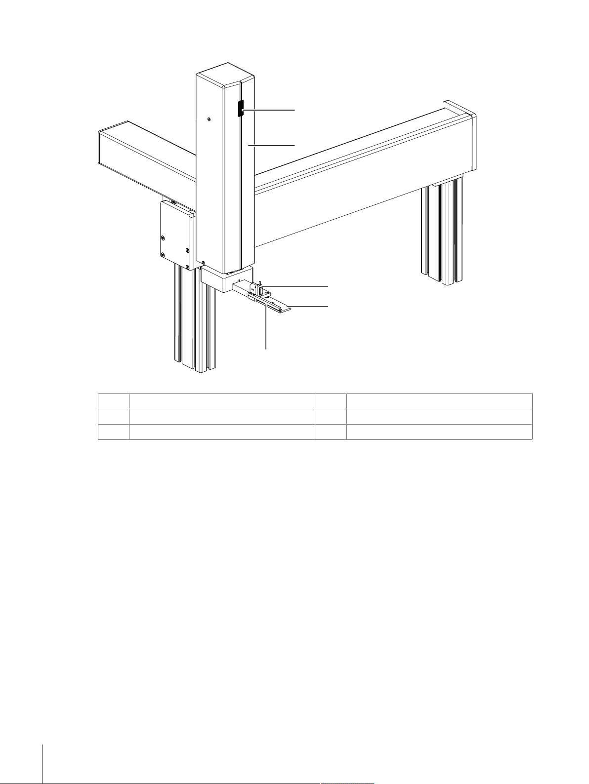
3.2.3 Overviw robot system
1
2
3
4
5
Legend overview robot system
Status indication light
1
Light barrier
3
Manipulator
5
2
4
Robot arm
Robot hand
Design and Function10 Robotic Mass Comparator
Page 13
3.2.4 Overview type plate
1
2
3
4
5
1 2 3 4 5
The type plate of the robot system is located on the backside of the robot system next to the socket for the AC/
DC adapter.
Legend overview type plate
Model designation
1
Power supply
3
Serial number (SNR)
5
Year of manufacture
2
Manufacturer
4
3.2.5 Overview robot system control unit
Legend overview robot system control unit
RS232C (balance control unit)
1
Ethernet (not applicable)
3
Sockets for AC/DC adapter
5
3.2.6 Control software
All settings and the operation of the instrument are controlled with the software e100control. The software is
installed on a notebook provided by METTLER TOLEDO.
The software is used to visualize the instrument data and measuring results and to interact with the instrument.
The interaction encompasses starting and aborting weighing processes, configuring the instrument and defining
process specific data (as comparison scheme etc.).
RS232C (PC with control software)
2
Socket for interface cable robot system
4
Design and Function 11Robotic Mass Comparator
Page 14
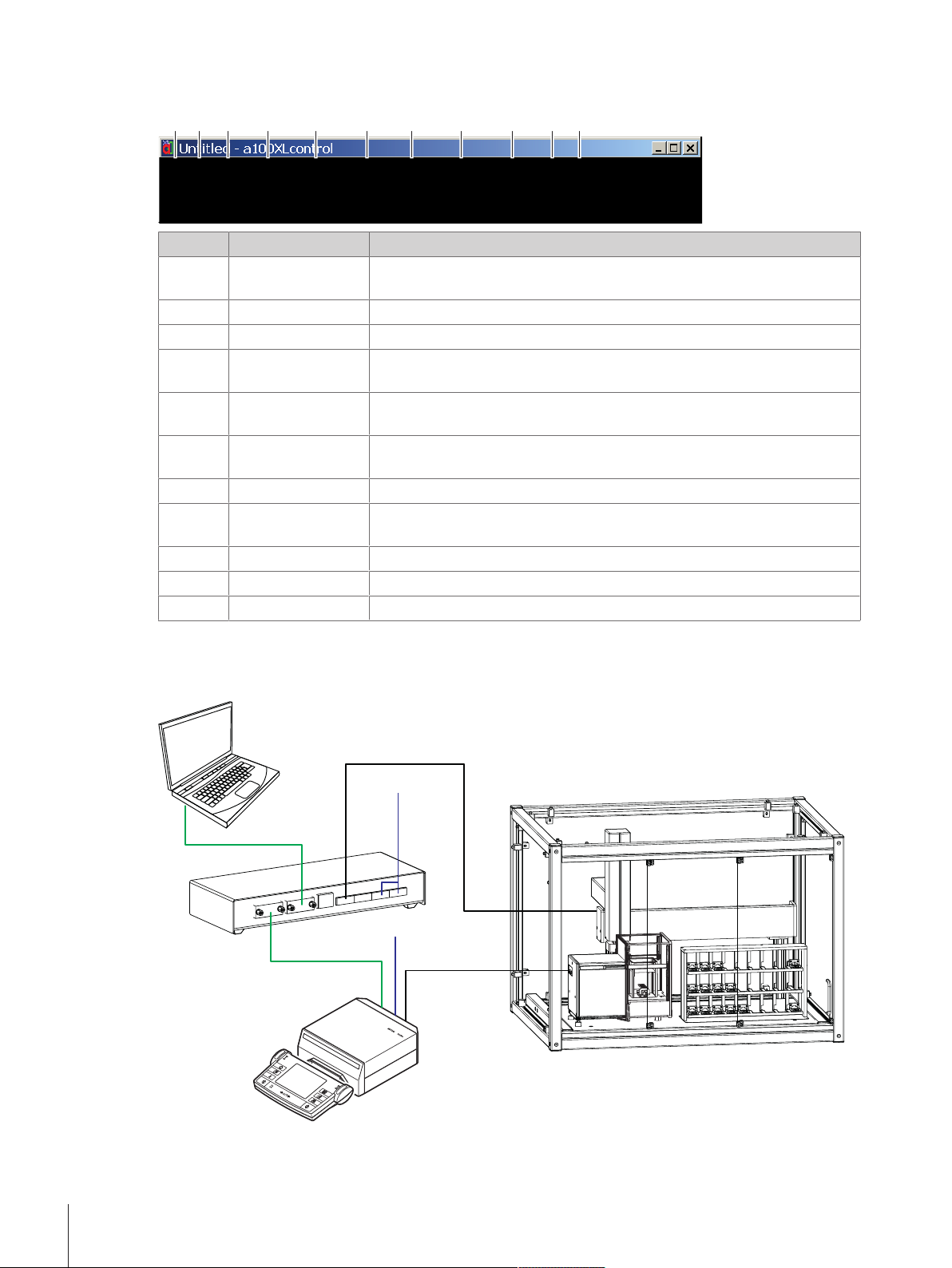
The following illustration gives an overview about the main functions of the software. For further information see
1 2 3 4 5 6 7 8 9 10 11
RS 232
RS 232
AC
AC
Cable load
cell
Cable robot
control
[Operation}Page22]:
Nr. Parameter Description
1 File
Contains file related commands like creating a new file, opening an existing
file, importing a text file, saving current file, quitting program etc.
2 Edit
3 View
4 Weights
Contains various functions to edit the file (similar to Windows).
Contains various functions to adapt the view (similar to Windows).
Gives access to the weights database which contains all relevant data on
your standards and test weights.
5 Magazine
Opens the menu to identify and register the weights placed in the weight
magazine.
6 Process
Opens the menu to set comparisons of which the weighing process shall
consist, as well as its precise timing and sequence.
7 Report
8 Adjustment
Gives access to define the content of the report file.
Allows you to start the adjustment procedure using the built-in balance
adjustment weights.
9 System
10 Start
11 Help
Contains various system settings.
Hosts the command to start the measurement.
Contains the help file and further information about the software.
3.3 Wiring scheme
The illustration below shows how the different components of the instrument are connected to each other:
Design and Function12 Robotic Mass Comparator
Page 15
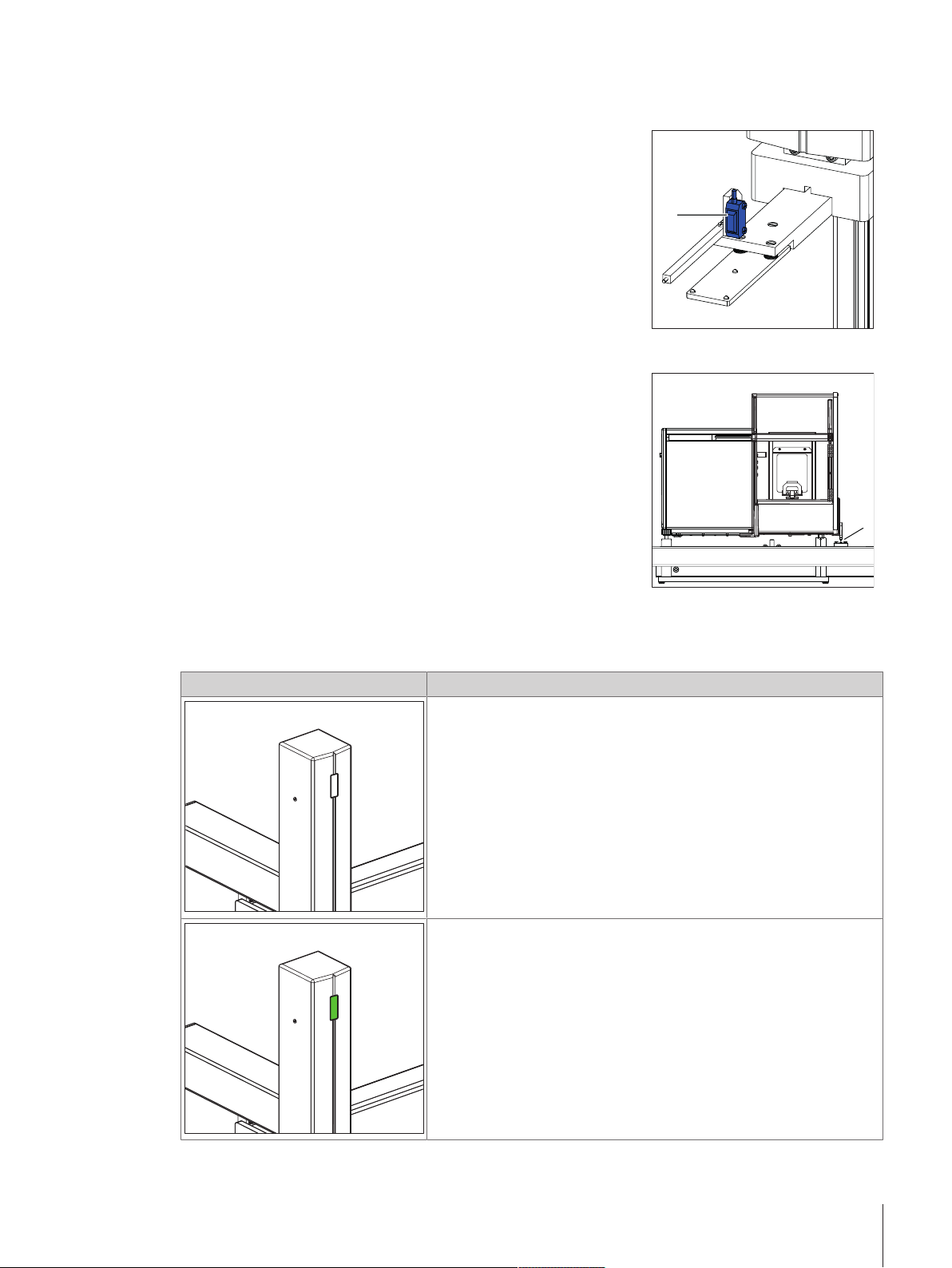
3.4 Safety devices
1
1
Light barrier
At the very beginning of the measurement each weight carrier is
checked by means of the light barrier located on the robot hand (1).
Should a unsuitable weight carrier be detected, the process aborts.
Balance position sensor
The position of the balance is monitored by means of the balance
position sensor (1). To avoid crashes, the balance must stay in the
position which was precisely defined during system installation.
Therefore, never move or reposition the balance (e. g. while cleaning).
Should a position error be detected, do contact a METTLER TOLEDO
representative.
3.5 Status indication light
The robot arm is equipped with a status LED. The LED indicates whether the instrument is enabled or not.
Status LED Meaning
LED is off
When the LED is off, the robot arm is not in operating mode. No
automatic movement of the robot arm is possible.
LED is on
When the LED is on, the robot arm is in operating mode. This means,
that the robot arm may move automatically.
Proceed with caution when performing manual operations while the
LED is on.
Design and Function 13Robotic Mass Comparator
Page 16
4 Installation and Putting into Operation
4.1 Selecting the location
CAUTION
Damage on instrument due to incorrect moving or unsuitable location site
Moving the instrument yourself might lead to injuries or might damage the instrument.
1 Contact a METTLER TOLEDO representative before changing the location of the instrument.
2 Do not carry the instrument yourself. It's total weight exceeds the acceptable limit in
accordance to the applicable regulations.
Note
Ensure that at least 30 cm free space is available on the left side of the instrument to position the balance
control unit and the robot system control unit. Its recommended to position the notebook on another table in
order to avoid interferences due to vibrations.
A balance is a sensitive precision instrument. The location where it is placed will have a profound effect on the
accuracy of the weighing results.
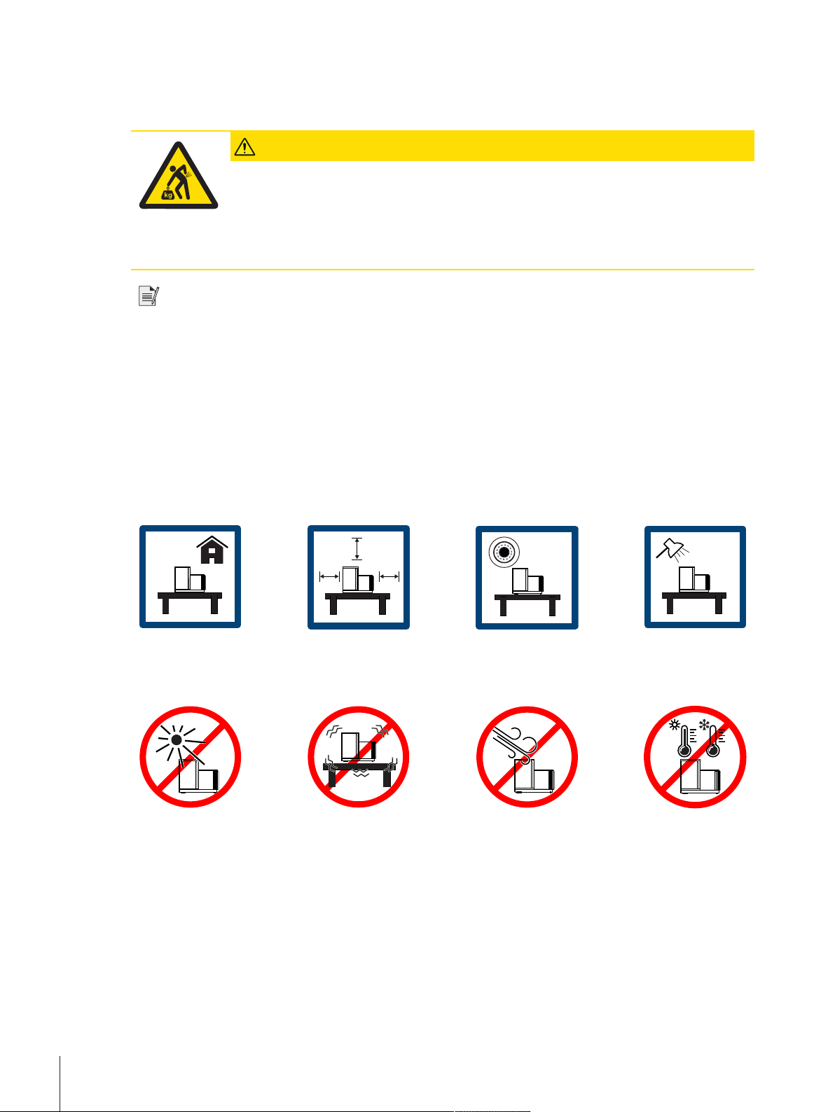
Requirements of the location
According to the environmental condition, see chapter "General data".
Ensure there is:
• indoor on
stable table
• with sufficient
distance (>
30 cm)
• in level • adequate lit
Avoid:
• direct sunlight • vibrations • strong drafts • temperature
4.2 Scope of delivery
• 3-axis robotic system with all electric components
• 1 Magazine with 27 positions
• 1 AX106 mass comparator
• 1 Draft shield
• 1 Controller (laptop)
• e100control software
• 16 Weight carriers design 1, e100
• 11 Weight carriers design 3, e100
fluctuations
Installation and Putting into Operation14 Robotic Mass Comparator
Page 17
• 3 Weight carrier inserts diameter 26 mm
• 2 Weight carrier inserts diameter 24 mm
• 4 Weight carrier inserts diameter 22 mm
• 2 Weight carrier inserts diameter 20 mm
• 4 Weight carrier inserts diameter 18 mm
• 4 Weight carrier inserts diameter 14 mm
• 4 Weight carrier inserts diameter 10 mm
• 4 Weight carrier inserts diameter 6 mm
• 1 Tweezer for 1 mg to 50 g
• 1 Tweezer for 1 g to 200 g
• 1 Rubber air bellow
• 1 User Manual
• 1 Declaration of conformity
• 1 Production certificate
4.3 Assembling the instrument
CAUTION
Injury and property damage due to inappropriate assembling and commissioning
of the instrument
Errors during the assembling and commissioning can cause life-threatening situations and
significant property damage.
1 Only allow assembling and commissioning to be handled by employees of the
manufacturer or people authorized by the manufacturer.
2 Do not attempt to handle installation and location changes yourself.
3 Contact METTLER TOLEDO prior to perform any task not described in this manual.
4.4 Connecting and setting up the instrument
WARNING
Death or serious injury due to electric shock
Contact with parts that carry a live current can lead to death or injury.
1 Only use the approved METTLER TOLEDO power supply cable and AC/DC adapter with a
current-limited SELV output.
2 Connect the power cable to a grounded power outlet, ensure correct polarity.
3 Keep all electrical cables and connections away from liquids and moisture.
4 Check the cables and power plug for damage and replace damaged cables and power
plugs.
NOTICE
Damage to the AC/DC adapter due to overheating
If the AC/DC adapter is covered or in a container, it is not sufficiently cooled and will
overheat.
1 Do not cover the AC/DC adapter.
2 Do not put the AC/DC adapter in a container.
Installation and Putting into Operation 15Robotic Mass Comparator
Page 18

Handling the AC/DC adapters
11
2
2
F
o
r
c
o
n
n
e
c
t
i
o
n
t
o
b
a
l
a
n
c
e
o
n
l
y
R
S
2
3
2
C
P
o
w
e
r
s
u
p
p
l
y
3
The balance is supplied with a universal AC/DC adapter or an AC/DC adapter with a country-specific power
cable.
• Install the cables so that they cannot be damaged or interfere with operation.
• Insert the power cable in a grounded power outlet that is easily accessible.
Note
When the instrument is connected to the power grid, it starts automatically. To switch off the instrument and to
disconnect it from the power supply, the power plug has to be plugged out.
Setting up the instrument
To power and set up the instrument proceed as follows:
NOTICE
Damaged balance because of weight or weight carriers on robot hand or balance
If the robot hand or the balance are not empty during the start up procedure, the balance can
get damaged.
− Make sure to remove everything from the balance and the robot hand before powering on
the balance.
The instrument is complete and fully cabled by the manufacturer. The balance and the robot system power
§
cables are not plugged in yet.
The robot hand and the balance pan are empty.
§
1 Make sure both control knobs (2) on the balance are
on position 0. If not, turn them manually to position 0.
2 Place a 100g weight on the weighing pan (1).
1 Connect the power cable (3) to the balance and the
control unit. Plug in the balance power cable (3).
ð The start-up procedure begins automatically. The
balance door opens and closes again.
2 Once the start-up procedure is completed, remove the
100g weight manually.
ð The balance is now powered.
1 Ensure that the cable between the robot system and the
robot system control unit (4) is plugged in.
Installation and Putting into Operation16 Robotic Mass Comparator
Page 19
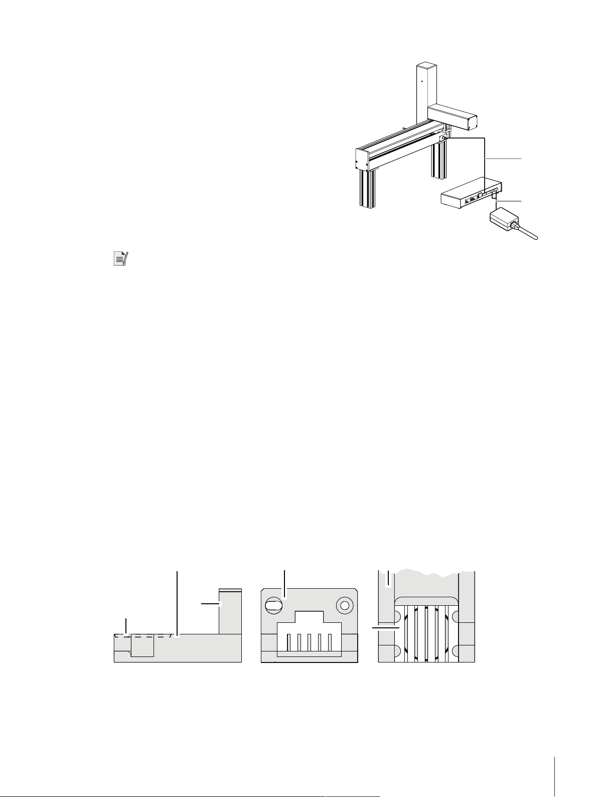
2 Plug in the power cable at the robot system control unit (5).
4
5
1
2
4
5
6
3
ð The robot system is now powered. The start-up
procedure includes the following steps:
• The carriage of the balance opens and closes.
• The robot system initializes. Each axis of the robot
system is driven to its respective home position.
• The robot hand opens and closes the balance door.
• The robot arm moves to its home position.
The instrument is set up and the weights can be loaded on
the weight magazine, see [Preparing the weight
magazine}Page17]. Prior to start weighing, wait at
least 120 minutes after connecting the balance to the
power supply. This allows the components to get at room
temperature.
Note
• If any of the following situations is detected, each robot axis is driven to its respective home position but no
further action is taken:
– Balance is turned off.
– Interface connection is inactive.
– Balance has been moved from its original position.
To ensure optimum weighing conditions, leave the robot system on all the time.
4.5 Preparing the weight magazine
Each test weight or standard used during the weighing process needs to be placed onto one weight carrier. The
selection of the adequate weight carrier type is determined by the weight geometry.
In order to ensure a trouble-free operation of the comparator and to minimize corner load errors, strict rules
must be followed when it comes to choose the right carrier type. Consult and follow the weight carrier selection
guide each time you load weights onto the magazine.
Pay attention to the following:
• Do not touch the weight carriers or the weights by hand. Use the delivered tweezers or powder free latex
gloves.
4.5.1 Selecting a suitable weight carrier
There are two designs of weight carriers available for this weight magazine.
Design nr. 1: small to medium weights
Installation and Putting into Operation 17Robotic Mass Comparator
Page 20
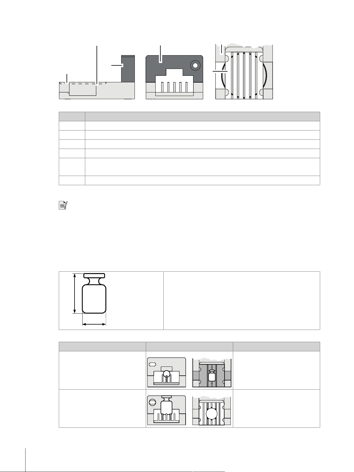
Design nr. 3: medium to big weights
1
6
5
4
2
3
hc
dc
Legend
Nr. Description
1
2
3
4
5
6
Side view
Front view
Top view
Sunken position for cylindrical weights
Grey frame for design nr. 1
Red frame for design nr. 3
Interchangeable insert
Choosing the correct insert
Note
• Weights which do not fit in one of the categories listed below must not be loaded on the carriers.
• Weights must never be placed over the edge of the sunken position.
In the mode down-/upward calibration combinations of up to three weights can be weighed:
• Design nr. 1: up to three weights, placed each on its own carrier, can be weighed.
• Design nr. 1 in combination with design nr. 3: up to two weights, placed each on its own carrier, can be
weighed.
The weight dimensions are measured including the weight knob.
Design nr. 1
Weight dimension Figure Insert
dc = 6 mm
hc ≤ 12 mm
Ø 6 mm
6 mm < dc ≤ 10 mm
hc ≤ 20 mm
Installation and Putting into Operation18 Robotic Mass Comparator
Ø 10 mm
Page 21
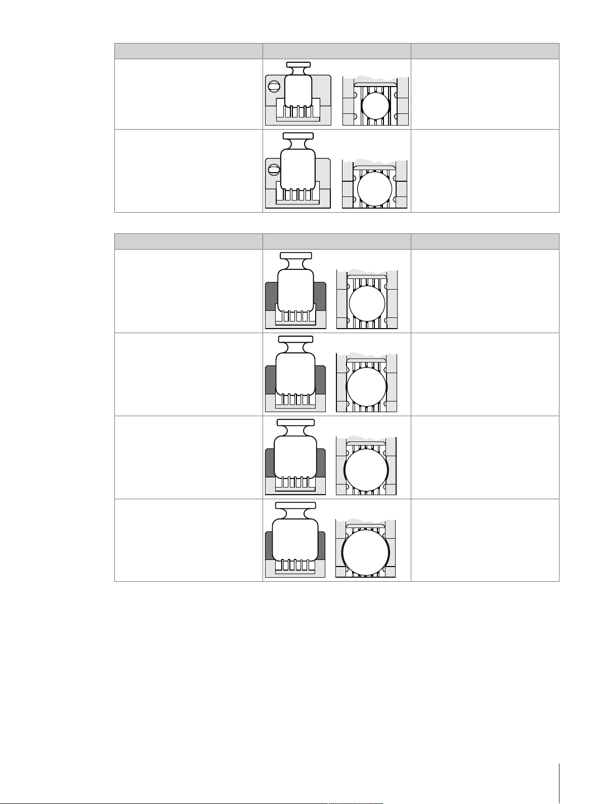
Weight dimension Figure Insert
10 mm < dc ≤ 14 mm
Ø 14 mm
hc ≤ 28 mm
14 mm < dc ≤ 18 mm
Ø 18 mm
hc ≤ 36 mm
Design nr. 3
Weight dimension Figure Insert
18 mm < dc ≤ 20 mm
Ø 20 mm
hc ≤ 40 mm
20 mm < dc ≤ 22 mm
Ø 22 mm
hc ≤ 44 mm
22 mm < dc ≤ 24 mm
Ø 24 mm
hc ≤ 48 mm
24 mm < dc ≤ 26 mm
hc ≤ 50mm
Ø 26 mm
Installation and Putting into Operation 19Robotic Mass Comparator
Page 22
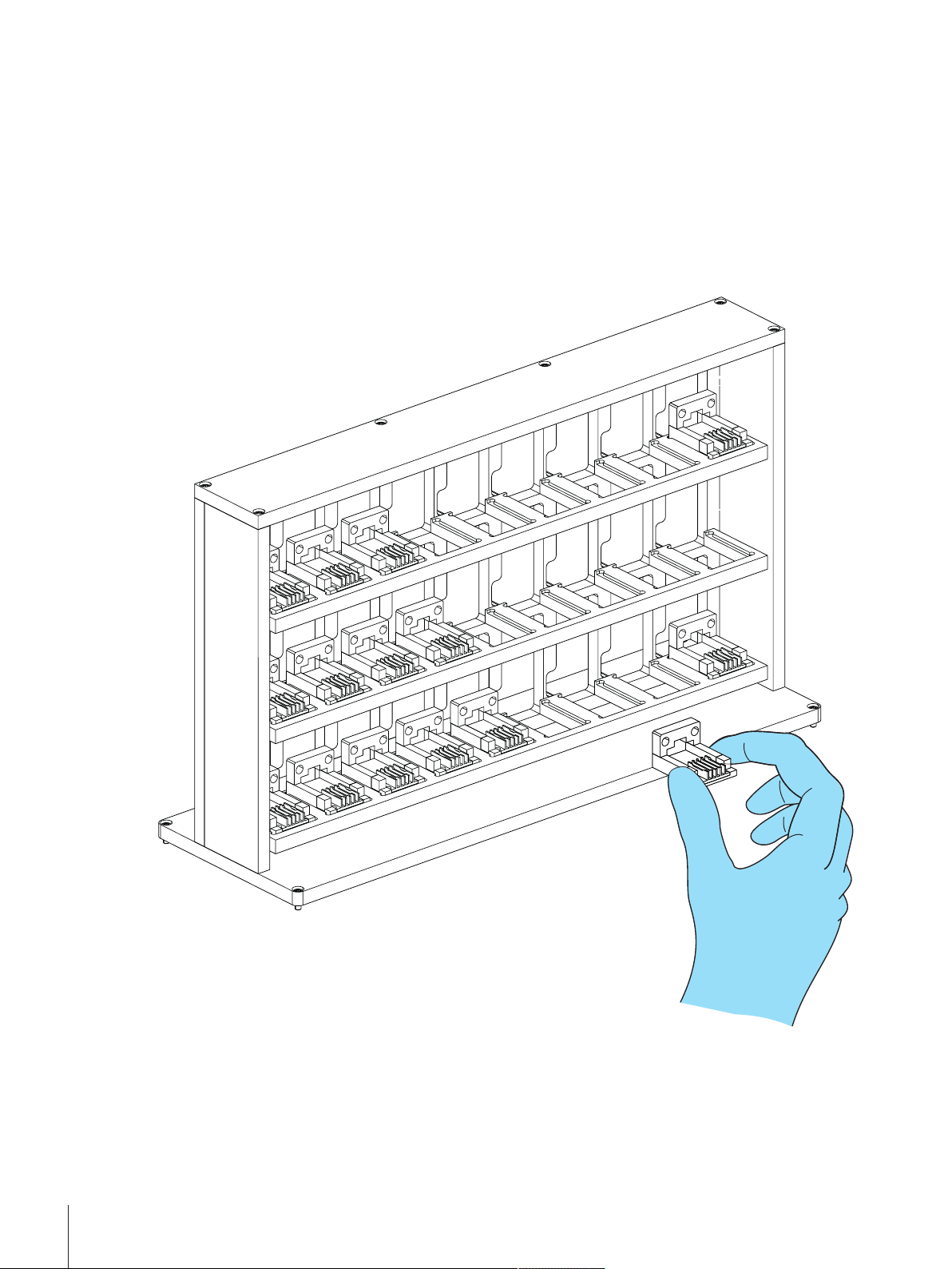
4.5.2 Loading the weight magazine
To place the weights onto their respective weight carrier in the magazine proceed as follows:
The instrument has been started successfully, see Setting up the instrument.
§
1 Open the weighing chamber doors.
2 Insert the respective weight carriers design nr. 1 or design nr. 3 into the weight magazine. To position the
weight carriers correctly, pay attention to the following:
3 - The carriers must be centered within the sunken frame of the magazine position.
4 - Do not touch the weight carriers by hand. Use the delivered tweezers or powder free latex gloves.
Installation and Putting into Operation20 Robotic Mass Comparator
Page 23
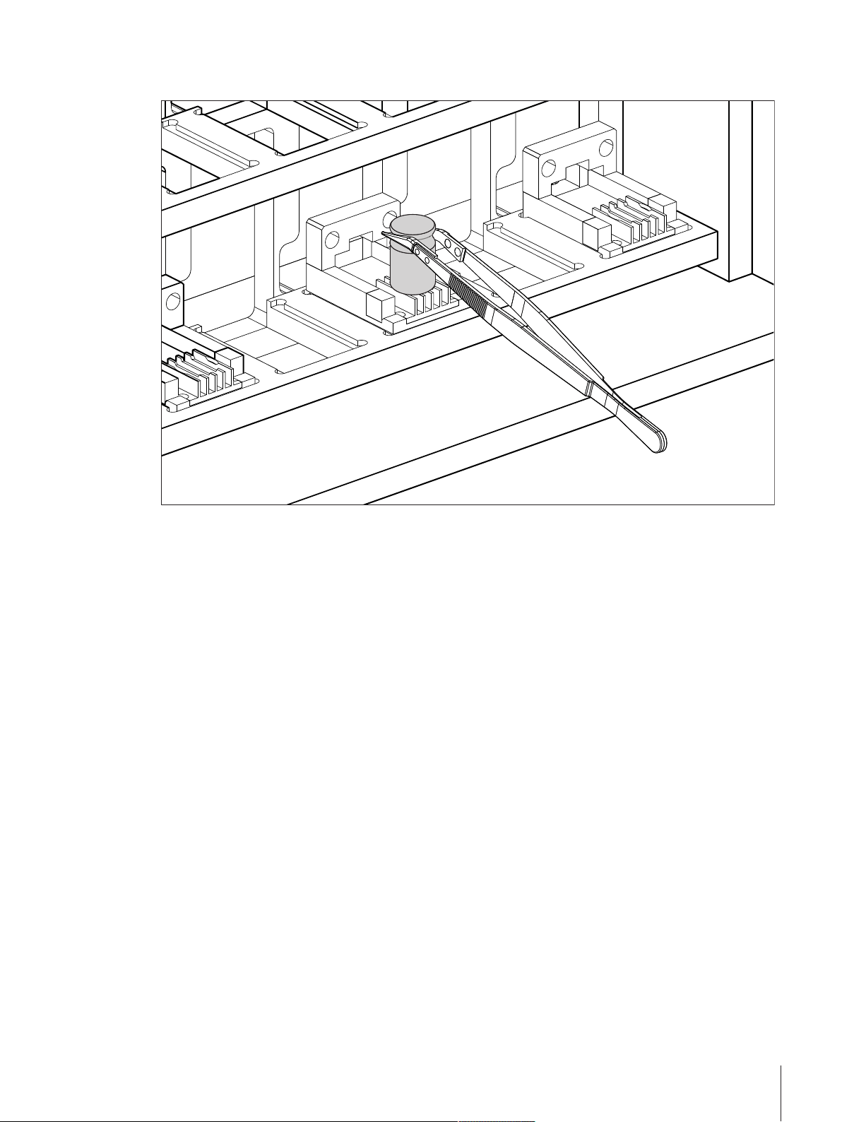
5 Place the weights on the respective weight carriers using the delivered tweezers. Do not touch the weights
by hand. Pay attention to place the weights the right way on the right carrier type.
6 Once the magazine is loaded, close the weighing chamber doors.
Installation and Putting into Operation 21Robotic Mass Comparator
Page 24
5 Operation
This section describes the e100control software and refers to its version 4.95.
5.1 Starting e100control
Starting e100control
− Double click e100control icon (e100control.exe) to start e100control.
ð The program starts and a new, blank settings file named 'Untitled.e100’ opens.
Description of the commands
The e100control main menu comprises the following items:
e100control - main window
Edit, View and Help offer functions and options that are standard in common Windows® applications and
therefore may not require further description. File lists the following commands:
e100control - File menu
Command Description
New
Open…
Import…
Save
Save As…
Operation22 Robotic Mass Comparator
Closes the current settings file and opens a new, blank file named ‘Untitled.e100’. If
changes were made to the currently open file, you are prompted to save them.
Prompts you to select and open an existing file. Once a particular file is selected, the
currently open settings file closes. If changes were made to it, you are prompted to save
them.
Prompts you to select an existing text file (extension ‘.imp’ or ‘.txt’), generated by an
external application according to a defined format, and converts it into a new standard
settings file (extension: ‘.e100’). The new settings file will immediately be loaded. For
details see [Remote-controlling the e100comparator}Page53].
Saves the changes made to the current settings file under the current file name
(extension: '.e100').
Prompts you to enter a new file name and saves the current settings file under the name
you just entered (extension: '.e100').
Page 25
Command Description
Save as Text…
This command allows you to select and save, in the current directory but in a separate
text file (current name with extension ‘.txt’), the settings which you may want to be
printed out separately and archived in your record. By ticking the adjacent boxes, you
may select the following options:
• Standards data for selected sets [Standards data}Page23]
• Test weights data [Test weights data}Page26]
• Magazine places allocation [Allocating the weight magazine places}Page27]
• Weighing process settings [Weighing process settings}Page29]
• Series scheme [Series scheme}Page31]
• Report heading [Starting the weighing process}Page37]
Exit Prompts you to save the unsaved changes you made and quits e100control.
5.2 Entering and editing the weights data
The Weights menu gives access to the weights database which contains all relevant data on your standards
and test weights. While the data on your test weights are, like other settings, specific to the process and, thus,
to the current settings file (extension .e100), the data on your standards are kept in a separate database
(‘MyStandards.st2’). These data are specific to your mass standards laboratory, not to the weighing process,
and, thus, need to be accessible from any settings file.
Noteworthy is the fact that ‘MyStandards.st2’ must be left in the same directory as your application file
(‘e100control.exe’) and your setting files. For safety purpose, you may want to keep a backup file of the
standards database.
e100control - Weights menu
5.2.1 Standards data
Entering standards data
To enter the standards data, proceed as follows:
1 Select Weights > Standards data….
ð The window shown below is displayed. A list box gives all standards which have been entered. All
entries are numbered (column Pos) and listed alphabetically by Set-ID (identification - limited to 8
characters - of the weight set to which this standard belongs) and by descending nominal values
Operation 23Robotic Mass Comparator
Page 26

(Nom.value [g]) given in gram only. Besides, each record contains a Standard-ID (identification limited to 8 characters - of this particular standard) and the error (Error [mg]), given in mg only, as
well as a field for some further information on this standard (Notes, limited to 35 characters).
Entering/editing standards data
2 Change the currently stored standards data by clicking either the Add…, Modify…, Delete or Delete all
command button.
3 Before allowing you to access the data and to modify them,
e100control prompts you to enter the password. The default
password is ‘’ (empty character string = no character).
Click Change… to change the password. Enter the current
password, the new one and, again, the new one as confirmation.
The password is limited to maximum 12 characters.
4 Once the password is accepted, you may proceed with the modifications (the access to the data remains
free until you close the Standards data window by clicking either OK or Cancel). For information
concerning the different commands, see the table below.
5 Once you are satisfied with the changes you have made, return to the main window by clicking OK. Should
you wish to ignore all the changes made, click Cancel.
ð The standards data are stored in the file ‘MyStandards.st2’.
Operation24 Robotic Mass Comparator
Page 27
Overview about the commands
Command Description
Add… Opens the Add standards data window which allows you to enter a new record in the
standards database. Return to the Standards data window after confirming your new
entry OK or ignoring it Cancel.
Modify… Opens the Modify standards data window which allows you to modify the error and the
notes. Return to the Standards data window after confirming the changes OK or
ignoring them Cancel.
Default density…
Delete
Delete all
Save as text
Opens a window where the default density can be entered. This default density is used
when a new standard is added.
The button is inactive, if standards and test weights have no density values, see
[Selecting the application mode}Page60].
Deletes the record which is presently selected (to select a particular record from the list,
simply click on it).
Deletes all database records.
This command allows you to save, in the current directory but in a separate text file
(‘MyStandards.txt’) the standards data which you may want to be printed out separately
and archived in your record.
Selecting a standards set
As above described, each standard belongs to a particular set, identifiable through its Set-ID. In your mass
standards laboratory, likely more than one set are available, so that you may wish to select only one (or more)
particular set to be used during the weighing process which you are preparing. To do so, proceed as follows:
1 Select Weights > Standards sets selection….
ð The window Standards sets selection is displayed.
2 Select in the Not selected list the set you want to use for this particular weighing process.
Operation 25Robotic Mass Comparator
Page 28

3 Click «.
ð The weights belonging to the non-selected sets will not appear in any of the windows in which e. g. the
magazine places are allocated, the series scheme is designed etc..
Selecting a standards set
5.2.2 Test weights data
Entering test weights data
To enter the test weights data, proceed as follows:
1 Select Weights > Test weights data….
ð A window entitled Test weights data is displayed. A list box gives all test weights which are to be
determined during this particular weighing process. All entries are numbered (column Pos) and listed
alphabetically by Set-ID (identification - limited to 8 characters - of the weight set to which this test
weight belongs) and by descending nominal values (Nom. Value [g]) given in gram only. Besides,
each record contains a Weight-ID (identification - limited to 8 characters - of this test weight) and a
field for some further information on this test weight (Notes), limited to 35 characters.
2 Following the procedure described in [Standards data}Page23], change the presently stored test weights
data by using one of the commands in the table below.
3 Once you are satisfied with the changes you have made, return to the main window by clicking OK. Should
you wish to ignore all the changes made, click Cancel.
Overview about the commands
Command Description
Add… Opens the Add test weights data window which allows you to enter a new record in the
list of test weights. After entering a Set-ID and a nominal value, you may use the auto
numbering button to create up to 100 test weights all having the same Set-ID and
nominal value, and consequent numbers as weight ID’s.
Example: Entering ‘00145’ as first number and ‘00180’ as last number will create 36
test weights, with Weight-ID’s ‘00145’, ‘00146’, and so on, up to ‘00180’.
Return to the Test weights data window after confirming your new entry OK or ignoring
it Cancel.
Modify… Opens the Modify test weights data window which allows you to modify the notes.
Return to the Test weights data window after confirming the changes OK or ignoring
them Cancel.
Operation26 Robotic Mass Comparator
Page 29

Command Description
Change Set ID… Opens the Change Set ID window which allows you to change the Set ID of all test
weights belonging to one test weights set. This gives you an excellent possibility to
adapt a saved settings file to a new measurement, just by changing the Set-ID of the test
weights involved in the measurement.
Default density…
Delete
Delete all
Opens a window where the default density can be entered. This default density is used
when a new test weight is added.
The command is inactive, if standards and test weights have no density values, see
[Selecting the application mode}Page60].
Deletes the record which is presently selected in the list box (in order to select a
particular record from the list, simply click on it).
Deletes all records.
5.3 Allocating the weight magazine places
Once the standards and test weights are defined in their respective database, their position on the weight
magazine needs to be identified and registered in e100control. For this purpose, proceed as follows:
− Select Magazine > Places allocation….
ð The window Allocation of weight magazine places is displayed.
Allocating magazine places
Operation 27Robotic Mass Comparator
Page 30

The Allocation of weight magazine places window contains two list boxes:
• The upper one shows all defined weights - i. e. all standards which belong to the selected sets [Standards
data}Page23], identified by an ‘S’ in the ‘S/T’ column, and all test weights [Test weights data}Page26]
identified by a ‘T’ in the ‘S/T’ column.
• The lower list box shows all available magazine places, identified by their number:
– from a1 (left) to a9 (right) for the most upper magazine row
– from b1 (left) to b9 (right) for the 2nd magazine row
– from c1 (left) to c9 (right) for the lowest magazine row
The allocation of one magazine place to one weight selected from the upper list is made as follows:
1 Select the weight by clicking on the proper record in the upper list box.
2 Select, by clicking on the proper line in the lower list box, the magazine place you want to be allocated to
the weight you just selected.
3 Click Place.
ð The selected weight is removed from the upper list box, and entered into the lower one, on the line
which carries the number of the magazine place which is now allocated to this particular weight
(placing a weight whose nominal value exceeds 111 g is rejected).
4 Should a place be wrongly allocated, clear it again by
selecting it in the lower list box and clicking Clear.
Should all places have to be cleared, click simply
Clear all.
ð The weight data which were contained in the
cleared record are transferred back into the upper
list box.
5 Once the allocation of the magazine places is
completed, click OK, if you wish the allocation to be
confirmed, or Cancel, to ignore it, and return to the
main window.
Magazine places allocation completed
Note
• An alternative to the above described procedure - which has to be repeated for each weight to be used
during the weighing process - is to place all weights by default. To do so, simply click Place all by default.
See also
2 Entering and editing the weights data}Page23
5.4 Determining the weighing process settings and series scheme
After defining standards and test weights and determining on which magazine place each of these weights is
located, you need now to set the comparisons of which the weighing process shall consist, as well as their
precise timing and sequence.
It might be useful at this point to clarify the terminology used to identify the main phases of any weighing
process:
Operation28 Robotic Mass Comparator
Page 31

Term Description
Comparison or
(comparison)
Each single comparison between a weight (or a combination of weights) B, and a
weight (or a combination of weights) A.
weighing
Group
Sequence of n identical and successive comparisons, whose results are statistically
exploited.
Series
Sequence of all groups. The comparison (weight B vs. weight A) performed in each
group and the sequence of all groups are defined in the series scheme (design).
(Weighing) process
Sequence of n identical and successive series, preceded by the following (if so
requested):
• Centering phase: centering of all weight carriers on their respective magazine place
• Pre-run: check of the nominal value of each weight
• Waiting time: start delay
5.4.1 Weighing process settings
1 Select Process > Settings….
ð The window Weighing process settings is displayed.
Setting the process parameters
2 After opening the Weighing process settings window, you may determine the following parameters:
Operation 29Robotic Mass Comparator
Page 32

Parameter Description
Weighing mode
Provided your system is equipped with the ‘professional’ software edition, i. e.
e100control with option for down-/upward calibration, you can choose between the
following options:
• One-vs.-one comparisons: direct comparisons between a single weight B and a
single weight A
• Down-/upward calibration: comparison between two combinations of up to three
weights each
The ‘standard’ software allows One-vs.-one comparisons only.
Default setting: One-vs.-one comparisons
Pre-run requested
By ticking the adjacent check box, the system carries out an initial check which
basically consists in comparing the measured value of each weight with its defined
nominal value. Any placing error is indicated in a message box and causes the process
to abort.
It is strongly recommended to activate the Pre-run requested.
Default setting: Pre-run requested: check
History-specific
pause requested
By ticking the adjacent check box, the system makes certain that a minimum time
elapses between the last measurement of the previous group and the first reported
measurement of the current group, under the following circumstances only:
• At least one of the weights involved in the current group - but not all of them -,
whose nominal value equals or exceeds 10 g, was involved in the previous group
as well.
• The effective duration of the pause is determined as the duration of the 'history-
specific pause' (entered, in minutes, in the adjacent input box) minus the estimated
duration of the non-reported pre-weighings of the current group (should this
difference be negative, the effective duration of the pause is zero).
• This measure eliminates the drift affecting the weight difference between two weights
when one of them has reached a higher temperature than the other because of a
longer exposure to the environment of the balance weighing chamber which is
slightly warmer than the environment of the weight magazine.
Recommended and default setting: History-specific pause requested: check 20 min
Start delay
Time, entered in hours and minutes, between the end of the initial check(s) (centering
and, if requested, pre-run) and the start of the first series.
Default setting: 0 h 0 min; max.: 99 h 59 min
No. of nonreported
preweighings per
group (0-5)
In order to reduce the 'first weighing effect' (drift) noticeable in particular after a change
of nominal value, you may want the system to carry out one or several pre-weighing(s)
without getting the data reported. Each pre-weighing consists in the sequence A-B,
regardless of the selected comparison scheme.
Recommended and default setting: ‘3'
No. of reported
comparisons per
Number of statistically independent comparative weighings in each group.
Default setting: '5'
group (1-20)
No. of series (1-20)
Number of series.
Default setting: '1'
Stabilisation time
(10-60 s)
Time in seconds between loading the balance pan and start of the reading period whose
duration is determined under Integration time (0-60 s).
Default setting: '25' s
Integration time
(0-60 s)
Time in seconds which runs after the stabilisation time has elapsed and during which
the system records one measurement value every second. The average of the recorded
values is given as result in the measurement report.
Default setting: '5' s
Operation30 Robotic Mass Comparator
Page 33

Parameter Description
Comparison scheme You may choose either the A-B-A or A-B-B-A scheme. For details see [Calcu-
Sensitivity check
Sensitivity check
standard
Note
• The Weighing process (total) is an estimation of the total time needed to complete the weighing process.
To save a changed parameter, click Update.
5.4.2 Series scheme
As a next step, it remains to determine the series scheme (design), i. e. which comparisons shall be performed
and in which sequence. For this purpose, proceed as follows:
− Select Process > Settings… > Series scheme….
ð The window Series scheme is displayed.
lations}Page45].
Default setting: A-B-A
Should you wish to monitor the balance 'sensitivity' (in its electrical weighing range)
during the weighing process, select Check after each series. The sensitivity check -
determination of the value of the check standard (see next item) - will be performed
before the first series starts and at the end of each series). Each sensitivity check
consists of the non-reported sequence 0-B (pre-check), followed by the reported
sequence 0-B-0.
Default setting: No check
Provided the sensitivity check was requested (see previous item), this list box shows all
standards whose nominal value does not exceed 11 g and to which a magazine place
is allocated. The check standard is chosen by clicking on one of the records.
Operation 31Robotic Mass Comparator
Page 34

5.4.2.1 Series scheme in mode 'One-vs.-one comparisons'
If the mode One-vs.-one comparisons is selected, the following window is displayed:
Determining the series scheme in mode One-vs.-one comparisons
Before setting the series scheme, you need to consider the following three options:
• Comparisons between weights of different nominal values enabled: if so requested, tick it off by clicking
in the adjacent check box
• Comparisons between standards enabled: if so requested, tick it off
• Comparisons between test weights enabled: if so requested, tick it off
The upper left list box (Weight B:) contains all the weights which are available as weight B (“test weights”).
This list contains either:
• All available test weights to which one magazine place is allocated, provided Comparisons between
standards enabled are not enabled (middle check box not ticked)
• All available test weights and all selected standards to which one magazine place is allocated , provided
Comparisons between standards enabled are enabled (middle check box ticked), see [Allocating the
weight magazine places}Page27]
The upper right list box (Weight A:) contains all the weights which can be chosen as weight A (“standard”) for
the presently selected (clicked) weight B (“test weight”), according to the values given to the above described
check boxes. The series scheme consists of a list of comparisons between two single weights - weight B vs.
weight A - which will be performed in the order of their entry (amendments can be made to the sequence as
explained below).
Each comparison is entered as follows:
Operation32 Robotic Mass Comparator
Page 35

1 Select first the weight B by clicking on the proper record in the Weight B: list box.
2 Select the weight A by clicking on the proper record in the Weight A: list box.
3 Click Add.
ð A new comparison - selected weight B vs. selected weight A - is entered in the Scheme: list box.
4 Repeat the above sequence until the new series scheme is fully determined.
5 Once the series scheme is completed, click OK to store it. By clicking Cancel, the modifications are ignored.
Further commands
Command Description
Default scheme
Delete
Delete all
Move last entry
See also
2 Weighing process settings}Page29
Instead of entering each comparison one after the other, you may prefer to let
e100control propose its own scheme. By clicking the command e100control selects for
each weight B a matching weight A.
The command is active only if none of all 3 options is enabled.
To delete a wrong entry in the scheme.
To delete all entries in the scheme.
The sequence of comparisons can be changed by moving the last entry up:
1 Select the line up to which you want the last entry to move.
2 Click Move last entry.
ð The record on the selected line and all records below it are consequently shifted
downward.
Operation 33Robotic Mass Comparator
Page 36

5.4.2.2 Series scheme in mode 'Down-/upward calibration'
If the mode Down-/upward calibration is selected, the following window is displayed:
Determining the series scheme in mode Down-/upward calibration
The upper list boxes Weight B: and Weight A: both contain all available weights, i. e. all test weights and all
standards to which one magazine place is allocated, see [Allocating the weight magazine places}Page27].
The series scheme, displayed in the lower list boxes (Scheme - Weight B: and Scheme - Weight A:), consists
of a list of comparisons between two combinations of up to three weights each. These comparisons will be
performed in the order of their entry (amendments can be made to the sequence as explained below).
Each comparison is entered as follows:
1 Select first the weight B by clicking on the proper record in the upper Weight B: list box.
2 Click Add B.
ð The selected weight B is entered in the Scheme - Weight B: list box.
3 If you wish to enter a combination of more than one weight, repeat the previous two steps (the symbol ‘+’
in the Scheme list boxes indicates that a combination is entered and the total nominal value of the combination is displayed on the top of the Scheme list boxes).
4 Once the (combination of) weight(s) B is entered, select the weight A by clicking on the proper record in the
upper Weight A: list box.
5 Click Add A.
ð The selected weight A is entered in the Scheme - Weight A: list box.
6 If you wish to enter a combination of more than one weight A, repeat the two previous steps.
7 Repeat the above sequence until the new series scheme is fully determined.
Operation34 Robotic Mass Comparator
Page 37

8 Once the series scheme is completed, click OK to store it. By clicking Cancel, the modifications are ignored.
Note
• Should the nominal value of a weight combination exceed 111 g, the scheme entry is rejected.
Further commands
Command Description
Default scheme
Instead of entering each comparison one after the other, you may prefer to let
e100control propose its own scheme. By clicking the command e100control selects for
each weight B a matching weight A.
The command is active only if none of all 3 options is enabled.
Delete
Delete all
Move last entry
To delete a wrong entry in the scheme.
To delete all entries in the scheme.
The sequence of comparisons can be changed by moving the last entry up:
1 Select the line up to which you want the last entry to move.
2 Click Move last entry.
ð The record on the selected line and all records below it are consequently shifted
downward.
Complete series scheme in mode Down-/upward calibration
See also
2 Weighing process settings}Page29
Operation 35Robotic Mass Comparator
Page 38

5.5 Choosing the report contents
Before starting the weighing process, the contents of the report file can be defined. For this purpose, proceed as
follows:
1 Select Report > Contents….
ð The window Report contents is displayed.
2 Enter a User name.
3 Enter some Notes (brief description of the process) which will help ensure an easy traceability of your
measurement reports.
4 Define of which information blocks the report, produced both in a text (Microsoft® Word® file: ‘.doc’
extension) and spreadsheet (Microsoft® Excel® file: ‘.xls’ extension) format, shall consist.
See an example of a report printout in [Measurement report}Page40].
Note
• The report file name itself is not yet entered at this point: e100control will prompt you to define it once the
Start command is given.
Defining the report contents
Note
• An efficient way of exploiting e100control’s flexibility is to define the settings file (.e100) as a template for a
particular measurement (e. g. ‘100g-10g.e100’: settings file for the determination of a 100 g - 10 g weight
set) and to describe the job specifics (e. g. reference of the person/organization who is responsible for this
particular weighing process, reference of the person/organization who placed the order for these services
etc.) in the report under User name and Notes.
See also
2 Starting the weighing process}Page37
2 Measurement report}Page40
5.6 Adapting system settings
Before starting the weighing process, the serial communication needs to be established and the controller’s
serial port properly set. Proceed as follows:
Operation36 Robotic Mass Comparator
Page 39

1 Select System > Comparator serial port….
ð The window Serial port is displayed.
2 Activate the port to which the interface cable 1 is connected.
The other menu points in the System menu are explained later in this Reference Manual:
Menu point Description
Import/Export mode… See [Importing an externally defined settings file into
e100control}Page56]
Application mode… See [Selecting the application mode}Page60]
Software upgrade… See [Upgrading e100control}Page52]
Corner load error measurement… See [Measuring the corner load error}Page49]
Balance pan adjustment...
For METTLER TOLEDO service purposes only.
Email sender configuration… See [Sending emails}Page66]
ReportTransmitter configuration…
For information how to transmit measurement report data to a
TCP/IP server using ReportTransmitter configuration… see
[Transmit measurement report data to a TCP/IP
server}Page69].
Standard’s centering history…
For information how to reduce pre-run/centering time using
Standard’s centering history… see [Reduce pre-run/centering
time using ‘Standard’s centering history’}Page68].
5.7 Starting and monitoring the weighing process
5.7.1 Starting the weighing process
Preconditions
Prior to start the weighing process, ensure the following:
• The needed weights are positioned on the respective weight carriers in the magazine,
see [Preparing the weight magazine}Page17].
• The weights data (test weights and standards data) are entered in e100control,
see [Entering and editing the weights data}Page23].
• The weight magazine places are allocated in e100control,
see [Allocating the weight magazine places}Page27].
• The weighing process settings and the series scheme are determined,
see [Determining the weighing process settings and series scheme}Page28].
• If needed, the content of the report is defined, see [Choosing the report contents}Page36].
• All system settings are adapted to the instrument, see [Adapting system settings}Page36].
Starting the weighing process
To start the weighing process, proceed as follows:
1 Select Start > Start measurement.
2 Once the process is started, enter the name and location of the measurement report file.
3 Confirm your entry by clicking Save (clicking Cancel would abort the process).
Operation 37Robotic Mass Comparator
Page 40

4 After creating the report file, e100control displays a
message box which indicates the process timing, as
well as the maximum balance load. Click OK to pursue
the process (clicking Cancel would abort it).
5 Monitor the weighing process according to [Monitoring
the weighing process}Page38].
Entering the report file name
Weighing process information - Timing and maximum
balance load
5.7.2 Monitoring the weighing process
Overview
Once the weighing process has been started, e100control displays the weighing process monitor which allows
you to follow the process on-line, step by step. The two upper boxes Weight B: and Weight A: show which
comparison weighing is currently being carried out - which weight B vs. which weight A. The large text box first
reminds you of the process settings you defined; it records every single process step and displays the detailed
measurement data, in a format which is similar to the report format. Furthermore, it provides in the ‘status
field’ (area at the bottom left) useful information on the current action, as well as valuable advice with respect
to troubleshooting, should an error be detected.
Operation38 Robotic Mass Comparator
Page 41

Note
1
Should an error be detected, do pay careful attention to the information given in the process status field and
proceed accordingly.
Weighing process monitor
Commands
The following command buttons are available:
Command Description
Suspend and
Resume
The Suspend command interrupts temporarily the process and allows access to the
weighing chamber.
Stop The Stop command aborts the process. You are prompted to chose between aborting
the process immediately, and aborting the process after the robot system has brought
the weight(s), which is (are) being determined, back to the magazine. Should the
process be aborted, the measurement results gathered up to this point as well as the
summary table of the completed series are nevertheless documented in the report file.
Info… e100control indicates the estimated date and time of the completion of the
measurement process, as well as the time (in hours and minutes) remaining until
completion. Please be aware that the process is suspended as long as this information
window is open.
Exit
Closes the weighing process monitor and returns to the main window.
Initial checks
The process starts with a centering phase, during which each weight carrier is checked - by means of the light
barrier located on the robot hand (1) - and centered on its magazine position. If the pre-run is requested, each
weight is weighed and its nominal value checked, after its carrier has been centered.
The following initial checks are performed during centering/pre-run. Should a failure be detected, the process
aborts (except for the dead load check):
• The serial communication is established.
• The authorization was duly given for Down-/upward calibration, if selected.
Operation 39Robotic Mass Comparator
Page 42

• The authorization was duly given for Online climate data input, if selected.
1
• The robot hand is free of any weight carrier.
• The balance dead load - weight (force) generated by the electromagnetic balance sensor, when the balance
pan is free of any weight - has kept stable within an acceptable range since the last process start.
• Each allocated magazine place carries a weight carrier.
• If the mode Down-/upward calibration is chosen, no weight involved in a 3-weight combination is placed
on a weight carrier of design 3 (red frame, see [Selecting a suitable weight carrier}Page17]) - this check
is performed during the centering phase.
• During pre-run only: the difference between measured and nominal weight value does not exceed 10% of
the nominal value.
Checks during each weighing
Beside these initial checks, further ones are performed during each weighing. Should a failure be detected, the
process aborts:
• The carrier type (design) has not changed.
• The difference between measured and nominal weight (combination) value does not exceed 10% of the
(total) nominal value.
• The current group standard deviation, calculated after the second and each following comparison, does not
exceed 20 µg.
• The balance shows neither overload nor underload, once the robot hand has lowered the weight or weight
combination onto the balance pan.
Monitoring of sensors
Finally, the status of the balance position sensor is permanently monitored (see electrical drawing):
• The balance must stay in the position which was precisely defined during system installation - should a
position error be detected, do contact your supplier!
Before weighing, e100control sets the position of the four built-in tare weights in function of the nominal value
of the weight or weights combination. The set of tare weights consists of two 10 g weights, whose position is
set by means of a motor controlled via the balance interface, and two weights, 50g and 30 g, whose
respective position is set by means of a knob controlled by the finger of the robot hand (1).
5.8 Analyzing measurement data and report
5.8.1 Measurement report
The following figures show a report generated by e100control after running a weighing process consisting of
one series of 7 groups of 5 A-B-A comparison weighings. The selected weighing mode is Down-/upward
calibration.
Operation40 Robotic Mass Comparator
Figure 'Report - Part 1' shows the report heading, comprising the following information:
• The report file name (‘.doc’)
• The name of the settings file (‘.e100’)
Page 43

• The process start date and start time
• The duration of the process
• The user identification
• Some notes
• The weighing process settings
• The magazine places allocation
• The series scheme
• The balance settings
Note
• Be reminded that the report contents can be adapted to your needs, see [Choosing the report
contents}Page36].
Figure 'Report - Part 2' shows the measurement data. Each table line consists of the 8 following fields:
Field Description
Day/Time
Meas.no.
Measurement day and time recorded in day/hours:minutes:seconds.
Measurement number which indicates the series number, the group number and the
weighing number.
Example: ‘010203A’ stands for series no. 01, group no. 02, comparison no. 03 and
weight A. When a sensitivity check is carried out, the measurement number shows the
series number and ‘sc’ (for sensitivity check).
Place(s)
Indicates the magazine place(s) of the weight(s).
Noteworthy is the fact that, in case of a weight combination, the reported combination
(e. g. ‘a10 + b2 + b1’) differs from the combination entered in the series scheme (‘a10
+ b1 + b2’): it indicates in which order the weights were put onto the balance pan.
e100control chooses this order in such a way that the error due to corner load is
minimized (see 'Indication of corner load error' further in the current section).
Value
Indicates the recorded weight(s) value in mg. This value is the calculated average of all
values collected during the integration time [Weighing process settings}Page29] and
shows therefore an extra decimal place.
Diff. (B-A)
Indicates for each comparison the calculated difference between weight B and weight A.
The differences listed for a particular group are statistically independent [Calculations}Page45].
Diff.average
Indicates for each group the calculated average of all differences [Calculations}Page45].
WeightB-error
Indicates for each group the calculated error of the weight B, provided the error of the
weight A is known - this applies to a single standard only [Calculations}Page45].
Std.dev.
Indicates for each group the calculated standard deviation of the difference average
[Calculations}Page45].
If the climate data input source is online via serial port [Selecting the application mode}Page60], the
program collects online climate data and the measurement data table consists of additional fields: Each sensor
enabled to be reported has its own field.
Operation 41Robotic Mass Comparator
Page 44

At last, figure 'Report - Part 3' presents the results summary table from which you get, at a glance, the
essentials in a compact, but explicit format. Should the process consist of more than one series, the summary
table indicates the average of the difference averages (Average:).
Report - Part 1: heading and process settings
Operation42 Robotic Mass Comparator
Page 45

Report - Part 2: measurement data
Operation 43Robotic Mass Comparator
Page 46

Report - Part 2: measurement data (cont’d)
Report - Part 3: summary of results
Indication of corner load error
As above mentioned, e100control automatically handles the comparison of two weight combinations in such a
way (placing sequence) that the remaining corner load error is minimized. In the case of a comparison '20 g +
20 g + 10 g' vs. '50 g', the combination entered as '20 g + 20 g + 10 g' will be placed onto the balance pan
in the sequence '20 g + 10 g + 20 g': the center of gravity of the weights combination is located on the same
vertical axis as the 50 g weight and, consequently, the remaining corner load error equals zero. However, in
certain cases, in particular when non OIML weights are involved in a combination (e.g. '30 g + 20 g' vs. '50
g'), a certain error due to corner load remains. Knowing the measured corner load error, e100control
Operation44 Robotic Mass Comparator
Page 47

calculates for each comparison the remaining error due to corner load and, if not zero, indicates it under 'CrLd-
(Val_B
010101
- Val_A
010101
) + (Val_B
010101
- Val_A
010101’
)
Diff
010101
=
2
(Val_B
010102
- Val_A
010102
) + (Val_B
010102’
- Val_A
010102
)
Diff
010102
=
2
(Val_B
010103
- Val_A
010103
) + (Val_B
010103
- Val_A
010103’
)
Diff
010103
=
2
etc.
(Val_B
010101
+ Val_B
010101’
) - (Val_A
010101
+ Val_A
010101’
)
Diff
010101
=
2
(Val_B
010102
+ Val_B
010102’
) - (Val_A
010102
+ Val_A
010102’
)
Diff
010102
=
2
etc.
err' in the results summary table of the measurement report. The corrected difference average (not indicated in
the report) equals 'Diff.average' minus 'CrLd-err'.
Indication of corner load error
See also
2 Measuring the corner load error}Page49
5.8.2 Calculations
The figure below schematically represents the reported measurement data and the differences B-A calculated
during a weighing process, whose comparison scheme was set to A-B-A and A-B-B-A respectively. The calculations are given below for the series 1, group 01 as example.
The differences B-A are reported in the column Diff.(B-A) and, if the comparison scheme A-B-A was selected,
calculated as follows (see the figure below, top diagram):
If the comparison scheme A-B-B-A was selected, the differences B-A, reported in the column Diff.(B-A), are
calculated as follows (see the figure below, bottom diagram):
Operation 45Robotic Mass Comparator
Page 48

The difference average is reported, for each group of n comparisons, in the column Diff.average, and
n
Diff.average
0101
= (1 / n) å Diff
0101 i
i=01
n
S
td.dev.
0101
= [1 / (n-1)] å (Diff
0101 i
– Diff.average
0101
)
2
i=01
WeightB-error
0
101
= WeightA-error
0101
+ Diff.average
0101
(Val_SC00- Val_000) + (Val_SC00- Val_0
00’
)
Diff_SC00= (initial check)
2
(Val_SC01- Val_001) + (Val_SC01- Val_0
01’
)
Diff_SC01= (check done after series 01)
2
etc.
calculated as follows (for both comparison schemes):
The standard deviation of the difference average is reported, for each group, in the column Std.dev., and
calculated as follows (for both comparison schemes):
Provided the error of the weight A is known, the error of the weight B is reported, for each group, in the column
WeightB-error, and calculated as follows (for both comparison schemes):
Finally, if a sensitivity check was requested, the value of the selected check standard is reported in the column
Diff.(B-A), and calculated as follows (see the figure below, top and bottom diagram):
Val_SCi denotes the value measured after loading the check standard, Val_0i and Val_0i’ denote respectively the
zero point before and after loading the check standard.
Operation46 Robotic Mass Comparator
Page 49

The corner load error CrLd-err reported in the results summary table is calculated as follows (‘CrLd_err’ instead
CrLd_err = CrLd_errB- CrLd_err
A
1 ( M
A , B
)
2
CrLd_err
A , B
= × ( CrLd_err
measured, back
+ CrLd_err
measured, front
) ×
2 ( M
measured
)
2
1 M
A , B
+ × ( CrLd_err
measured, back
– CrLd_err
measured, front
) ×
2 M
measured
n-1 m
-1
with: MA= å ( weight_Ai× ecc_Ai) , MB= å ( weight_Bj× ecc_Bj) ,
i=0 j=0
and M
measured
= weight
measured
× ecc
measured
of ‘CrLd-err’, to avoid any confusion with the minus sign):
Key to above formulas
CrLd_err
CrLd_err
measured, front
measured, back
Measured corner load error, front position
Measured corner load error, back position
weight_A i , weight_BjNominal value in g of the weight i, resp. j, in the combination A of n weights, resp. B of
m weights
ecc_A i , ecc_B
Eccentricity of weight i, resp. j in the combination A, resp. B - i.e distance in mm
j
between the center of gravity of the weight and the vertical central axis of the balance
pan; this distance is positive for back position and negative for front position
weight
ecc
measured
measured
Nominal value in g of the check weight used for the measurement of the corner error
Eccentricity of the check weight used for the measurement of the corner load error - i. e.
distance in mm between the center of gravity of the check weight and the vertical central
axis of the balance pan; this distance is positive for back position and negative for front
position
Operation 47Robotic Mass Comparator
Page 50

The corner load error CrLd-err is not reported in the results summary table if its calculated value equals zero.
Displayed value comparison scheme A-B-A
Time
Val_0
00
Val_SC
0
0
D
iff_SC
00
Val_0
00’
Val_A
010103’
Val_A
010201
series 1, group 1
series 1, group 2
Val_B
01010
3
Val_A
010103
Diff
010103
initial sensitivity check
Displayed value comparison scheme A-B-B-A
Time
Val_0
0
0
Val_SC
0
0
Diff_SC
00
Val_0
00’
series 1, group 1
Val_A
010101
Val_B
010101
Val_A
010101’
Val_B
010102
Val_B
010102’
Val_A
010102
Val_A
010102
’
Diff
010102
Diff
010101
Val_B
01010
1’
Val_A
010101
Val_B
010101
Val_A
010101’
Diff
010101
Val_B
01010
2
Val_B
010102’
Val_A
010102
Diff
010102
Val_A
010201
’
Val_B
010201
Diff
010201
series 1, group 2
Val_A
010201
Val_B
010201
Diff
010201
Val_A
010201
’
Val_B
010201
’
Should the measurement of the corner load error not have been done and the calculated corner load error differ
from zero, the results summary table indicates CrLd-err: unknown.
Weighing process and reported measurement data - top diagram: A-B-A, bottom diagram: A-B-B-A scheme
Operation48 Robotic Mass Comparator
Page 51

See also
2 Measuring the corner load error}Page49
5.9 Adjusting the balance
The adjustment procedure has to be started from e100control, and not “manually”, i. e. not from the balance
control unit. To trigger the adjustment, proceed as follows:
1 Select Adjustment > Internal....
ð The window Adjustment with internal weights is displayed. The date and time of the last adjustment
are displayed. Under Tare weight: the 100 g standard weights, to which a magazine place is allocated,
are listed.
2 Select one of the tare weights before starting the adjustment.
3 Click Start to trigger the adjustment (or Cancel to return to the main window without taking any action).
ð From this point, the adjustment procedure runs automatically.
Starting the balance adjustment (with the internal weights)
5.10 Measuring the corner load error
Overview
As long as only direct comparisons are carried out and the selection of the weight carriers is made properly, the
error due to corner load is negligible. When combinations of weights are determined, the above statement is not
necessarily true; it is actually true only provided both weights combinations involved in the comparison can be
arranged on the balance pan in such a way that the centers of gravity of both combinations are located on the
same vertical axis (see Indication of corner load error, in [Measurement report}Page40]).
In the previously given example, i. e. '30 g + 20 g' vs. '50 g', the error due to corner load cannot be neglected.
Therefore, it is indicated in the report, as presented under Indication of corner load error. The indicated corner
load error is calculated from the so-called measured corner load error which is to be determined and updated
(or at least checked) on a regular - monthly - basis. The measured corner load error (front, back) is the
difference between the value of weight of a particular nominal value well centered on the balance pan and the
value of the same weight moved 21 or 17 mm (weight carrier of design 1 or 3) forwards, respectively
backwards from the vertical central axis of the balance pan.
Operation 49Robotic Mass Comparator
Page 52

Since the corner load error does depend not only on the value and the eccentricity of the weight (or weights
combination), but also on the distribution of the tare weights currently used, the corner load error values have
to be measured for all nominal values involved in your regular weighing processes (nominal values between
10 and 100 g can be selected). Again, the measurement of the corner load error needs to be done only if
combinations of weights with values which do not conform to the OIML recommendations are to be determined.
For each of these values, the date of the last corner load error measurement (or Not measured, if no
measurement has been done yet), as well as the current measured error values and the type of weight carrier
used for the measurement, are displayed. Besides, the Check weights list box displays all the standard
weights, or all weights (according to the setting of the top option button Check weights to use:), which are
appropriate for this particular measurement.
Measuring the corner load error
In order to determine or update the values saved as measured corner load error, proceed as follows:
1 Select System > Corner load error measurement….
ð The window Corner load error measurement is displayed.
Starting the measurement of the corner load error
2 Click on the appropriate list record in order to select the weight you wish to use.
Operation50 Robotic Mass Comparator
Page 53

3 Click Start to trigger the corner load error measurement (or click Cancel to return to the main window
without taking any action).
ð From this point, the measurement procedure runs automatically. Its results can be viewed in the Corner
load error measurement - Report window.
Report on the measurement of the corner load error
4 Once the procedure is completed, click Exit to return to the previous window.
ð e100control displays the values which have just been determined for the measured corner load error,
back and front.
5 Accept these values and update the currently saved errors accordingly by clicking OK, or reject the new
values and keep the currently stored ones by clicking Cancel.
Operation 51Robotic Mass Comparator
Page 54

Accepting OK or rejecting Cancel the new corner load error data
5.11 Upgrading e100control
If you acquired the ‘standard’ edition of e100control and now wish to upgrade it to the ‘professional’ one, or if
you wish to enable online climate data input, proceed as follows:
1 Select System > Software upgrade….
ð The window Software upgrade is displayed.
2 Enter in the Handler ID box the last four characters of the serial number of your e100 comparator (see
sticker on rear panel).
3 Enter the 8-character password you received upon purchase of the software option.
4 Click OK.
5 Should e100control ‘professional’ need to be re-installed on a controller, Handler ID and Password have to
be re-entered.
ð Your e100 comparator is now upgraded.
Operation52 Robotic Mass Comparator
Page 55

Upgrading the e100control software
5.12 Remote-controlling the e100comparator
The weighing process settings may need to be generated by a central laboratory information management
system, such as for instance the ‘Automated Mass Measurement System’ (AMMS) supplied by Measurement
Technology Laboratories (Minneapolis, USA), and imported from this system into e5control. Furthermore
certain commands may need to be sent to e5control from this central system, in order to let this system
“remote-control” the e5 comparator. e5control offers such an interface which fully meets these requirements.
5.12.1 Generating a file importable into e100control as settings file
As above mentioned, the ability of e100control to import a settings file generated by a central information
management system is indispensable to certain laboratories. To achieve this, a text file needs to be produced
by this central system according to well-defined format rules, so that it becomes convertible into a regular,
e100control-compatible settings file.
Operation 53Robotic Mass Comparator
Page 56

The figure below presents an example of such a text file, named ‘ImportDemo.imp’ and containing all
necessary settings according to their description and values given earlier on [Determining the weighing process
settings and series scheme}Page28].
Example of a text file convertible into a settings file by e100control
The format of this text file is defined in the figure below. The words written in upper case, bold letters (followed
or not by ‘:’), such as for instance REPORT: and END REPORT, are fixed identifiers which indicate the beginning
and the end of a parameter definition block. The other “words” are variables, i. e. parameters whose values numerical values or strings of characters - determine the information and settings specific to the weighing
process. The value of the following variables or parameters are to be determined within their respective range.
You may note that the prefix of their designation refers to their type:
• ‘str’ stands for ‘string’ (string of characters, without spaces unless otherwise specified)
• ‘bln’ for boolean (0 or 1)
• ‘int’ for ‘integer’ (exact whole number)
• ‘dec’ for decimal (number with decimal)
Operation54 Robotic Mass Comparator
Page 57

Format of a text file convertible into an e100control settings file (<CR LF> means ‘carriage return linefeed’ and [ ] optional)
Parameters
Parameter designation Value (range) Description
strJobID <no limitation> string of characters used as job identification
strAppName
‘e100control’
designation of control software used
intDocVersion 3 document version used as internal reference to the
settings definition and its history
strHeaderLine <no limitation> text appearing in a message box when loading the
imported and converted settings file
blnWeighingMode 0 | 1 ‘0’ = 1 vs. 1 comparisons, ‘1’ = down-/upward
calibration
blnPrerun 0 | 1 ‘0’ = pre-run not requested, ‘1’ = pre-run requested
intStartDelayHours 0 – 99 integer, number of hours in time requested as start
delay
intStartDelayMinutes 0 – 59 integer, number of minutes in time requested as start
delay
intNonReported-
Preweighings
0 – 5 integer, number of non-reported pre-weighings per
group
intReportedComparisons 1 – 20 integer, number of reported comparisons per group
intSeries 1 – 20 integer, number of series
strComparisonScheme ‘A-B-A’ | ‘A-B-B-A’ comparison scheme
intStabilisationTime 10 – 60 integer, stabilisation time in seconds
intIntegrationTime 0 – 60 integer, integration time in seconds
Operation 55Robotic Mass Comparator
Page 58

Parameter designation Value (range) Description
strSensitivityCheck strPosID | ‘NO’ mag. place of sens. check standard if check done,
‘NO’ if not
intHistorySpecificPause 0 – 60 integer, duration of history-specific pause in minutes
strPosID ‘a’ | ‘b’ | ‘c’ | & ‘1’ | ‘2’ |
…| ‘9’
magazine position number: a1 to a9, b1 to b9, c1 to
c9
strWeightType ‘S’ | ‘T’ ‘S’ = standard, ‘T’ = test weight
strSetID <maximum 8 characters> string of maximum 8 characters, weight set identifi-
cation
strWeightID <maximum 8 characters> string of maximum 8 characters, weight identification
decNominal 0 – 111 number (with decimal), weight nominal value in g
decError <no limitation, in
principle>
decDensity <no limitation, in
number (with decimal), error in mg given for
standards only (i.e. strWeightType = ‘S’)
number (with decimal), density in kg/m^3
principle>
strCombination strPosID[+strPosID
[+strPosID]]
strUserName <maximum 54
characters>
strFileName <file location path and
name>
string consisting of up to 3 different magazine
positions, separated by the ‘+’ sign
string of maximum 54 characters (including spaces),
user identification
name of report file, without extension, and its location
on disk
Meaning of the symbols used in the above table
• ‘< >’ delimits a comment on the value of a parameter
• ‘–’ means ‘up to’
• ‘ | ’ stands for ‘or’
• ‘[ ]’ delimits an optional block
• ‘&’ indicates the concatenation of two strings of characters
5.12.2 Importing an externally defined settings file into e100control
The file generated in the previous chapter (extension ‘.imp’) can now be imported into e100control and
converted into a settings file (extension ‘.e100’).
Selecting import source
Before importing the file, you need to select the data import mode between importing from file (accessible
locally on disk or via local area network) and importing via a serial communication port. Proceed as follows:
1 Select System > Import/Export mode… > Import source.
ð The window Import/Export mode is displayed.
2 Select the appropriate mode (File or Serial port).
3 Confirm with OK.
Note
• Should Serial port be selected, a second serial communication port has to be available - in addition to the
port used for communication to the e5 comparator weighing machine [Starting the weighing
process}Page37] - and selected as shown under Serial port.
Operation56 Robotic Mass Comparator
Page 59

Selecting the import mode ‘import via the serial communication port COM2’
Importing the file
Once the appropriate import mode is selected, the previously produced text file ‘ImportDemo.imp’ can be
imported into e100control and converted into the setting file ‘ImportDemo.e100’. To achieve this, proceed as
follows:
1 Select File > Import….
ð The window Select import file is displayed.
2 Select the text file you wish to import (extension ‘.imp’ or ‘txt’).
3 Click [Open].
ð The selected text file is parsed and checked, syntax-wise (see to the rules given in [Generating a file
importable into e100control as settings file}Page53]) and consistency-wise, as follows:
• The value of each parameter must be within the allowed range.
• The document version is currently 3: the document version is an internal reference to the settings definition
and its history.
• Should the sensitivity check be requested, the indicated magazine position must be allocated to a particular
weight in the ‘MAGAZINE’ block.
• An error must be specified for all standard weights.
• The number of weights in each combination must not exceed 3 and the total nominal value of each combi-
nation must not exceed 111 g; besides, the combinations to be compared must be comparable, i. e. the
difference between their respective nominal value must not exceed 11 g (electrical weighing range of the
balance).
• All magazine positions mentioned in the scheme must be allocated to a particular weight in the ‘MAGAZINE’
block.
• The path given for the output file must exist on the e100 comparator’s controller.
Should the text file be error-free, it is converted into an e100control settings file (extension ‘.e100’); the window
Save imported file opens and prompts you to enter the name under which this new settings file shall be
saved.
It is important to note that the standards database ‘MyStandards.st2’ – data on standards locally defined – is
not affected in any way when the weighing process settings are imported. The imported file contains all data
relevant to the definition of the standards involved in this process.
The imported settings are immediately loaded into e100control. You are informed in a message box that the
current weighing process settings are based on imported data, and that therefore these settings cannot be
altered, except for the Notes, see [Choosing the report contents}Page36]. Besides, this message box
displays the text defined in the ‘HEADER’ block of the source file, see [Generating a file importable into
e100control as settings file}Page53].
Operation 57Robotic Mass Comparator
Page 60

Everything is set, the weighing process can be started, see [Starting the weighing process}Page37]). The
measurement will be documented in the output file defined in the source file.
See also
2 Generating a file importable into e100control as settings file}Page53
5.12.3 Communicating via the serial port
The ‘.imp’ text file generated by the laboratory information management system (LIMS) can be imported into
e100control via a serial communication port. For this purpose, the option Import source: Serial port must be
selected in the Import/Export mode window.
Importing jobs
1 Select File > Import….
ð The window Import from serial port is displayed.
2 Click Get job list to get from the LIMS the list of the
pending jobs (settings files).
3 Once the pending jobs are listed in the Jobs: list box, a
particular job can be imported (loaded) into
e100control and converted into a settings file. For this
purpose click Load job.
ð Before converting the job into a settings file,
e100control parses and checks the text file to be
converted. Should it be error-free, it is converted
into an e100control settings file and the window
Save imported file opens.
4 Enter the name under which this new settings file shall
be saved.
5 If needed, repeat the procedure to import further jobs.
6 When finished, close the Import from serial port
window by clicking Exit.
Getting the list of pending jobs from the LIMS and
loading a particular job
Set of commands
The communication protocol is fixed: 2400 baud, 7 data bits, 1 stop bit, parity even; besides, a fixed time out
of 3 seconds is defined during which the reply to a request for data must be sent. To ensure a smooth
exchange of information between the LIMS and e100control, the following set of commands is available:
Task, description Command e100control --> LIMS Command LIMS --> e100control
Requesting list of pending jobs,
clicking Get job list
Sending list of pending jobs (empty
list if none available)
Requesting one particular job,
clicking Load job
Sending one particular job <text file as described in
Accepting job (file syntax and
consistency o.k.), saving job as
settings file
Rejecting job (file syntax and
consistency not o.k.)
JOB ?<CR LF>
JOB[ strJobID[ strJobID[…]]]<CR
LF>
JOB strJobID<CR LF>
[Generating a file importable into
e100control as settings
file}Page53]>
JOB strJobID OK<CR LF>
JOB strJobID DENIED<CR LF>
Operation58 Robotic Mass Comparator
Page 61

Task, description Command e100control --> LIMS Command LIMS --> e100control
23/19:38:49 00 sc 0 0.0130<CR LF>
23/19:40:05 00 sc a3 10000.0020<CR LF>
23/19:41:21 00 sc 0 0.0160<CR LF>
23/19:53:02 010101A a1 175.9270<CR
LF>
23/19:54:42 010101B a8 175.8134<CR
LF>
23/19:56:23 010101A a1 175.9288<CR
LF>
…
24/00:56:02 01 sc 0 0.1440<CR
LF>
24/00:57:17 01 sc a3 10000.1320<CR
LF>
24/00:58:33 01 sc 0 0.1440<CR
LF>
Advising of job start and estimated
duration, before pre-run/centering
JOB strJobID STARTS DURATION:
intHours:intMinutes<CR LF>
starts
Advising of job end, after job
successfully completed
Advising of job end due to program
JOB strJobID SUCCESSFULLY
ENDED<CR LF>
JOB strJobID ABORTED<CR LF>
failure, after program aborted
Advising of job end due to ‘Abort’
command given by user
JOB strJobID ABORTED BY
USER<CR LF>
The output data, i. e. the measurement results, can be sent out via the serial communication port and
processed on line by the LIMS. To achieve this, the option Export mode - Online output via serial port needs
to be selected in the Import/Export mode window and the serial communication port identified, as demonstrated in the figure below. (If the mode importing via a serial communication port is active, the same port is
used for data in- and output.)
Activating the on-line data output via the serial communication port COM2
While the weighing process is running, and provided the Export mode - Online output via serial port is active,
e100control sends on line the measurement data - without heading -, contained in the first four columns
(‘Time’, ‘Measurement number’, ‘Place(s)’ and ‘Value’) of the measurement data block of the report presented
in the figures below, for example:
After the weighing process is successfully completed, e100control sends out via the serial port a final data
block containing the corner load error, in mg, calculated for each measurement group (see [Measurement
report}Page40] and [Calculations}Page45]). The block format is as follows:
CORNERLOAD decCrLd_err1[ decCrLd_err2[ decCrLd_err3[ …]]]<CR LF>
Operation 59Robotic Mass Comparator
Page 62

where ‘decCrLd_err1’ is the corner load error calculated for the first measurement group, ‘decCrLd_err2’ the
corner load error calculated for the second measurement group etc. Should the error calculated for a particular
group equal zero or not have been measured, the value indicated for the error is ‘NO’ or ‘UNKNOWN’ respectively. An example of a complete block is given below, advising of the following corner load errors: 0 for the
first group, 0.0006 mg for the second group, -0.0005 mg for the third group and ‘unknown’ because not
measured for the fourth and last group.
CORNERLOAD NO 0.0006 –0.0005 UNKNOWN<CR LF>
5.13 Selecting the application mode
To select the application mode, proceed as follows:
− Select System > Application mode….
ð The window Application mode is displayed.
Selections in the application mode
Operation60 Robotic Mass Comparator
Page 63

Section Description
Weight densities
You can select if your standard and test weights have a density value or not. If you
choose with density value, a valid density value must be entered for each standard and
test weight.
Note
• If you select with density value and your standards and/or test weights database
already contains weights that have no density values specified, a warning is
generated to inform you that the densities of these weights are automatically set to
the value 8000kg/m3.
Climate data input
Here you can specify the climate data input source. Select between the following
options:
• none: No climate data input
• manual at measurement start: The climate data can be entered manually in a
window at measurement start.
• online via serial port: A climate measurement instrument (Klimet A30 or
compatible) can be connected to a serial port and the climate data are collected
online. Choose an available serial port from the Serial port list, and enable all
sensors to be reported by ticking the adjacent boxes.
• online from database (ODBC): Data will be read from an ODBC data source. See
the next sections for further details. Enter the name of the ODBC data source, the
name of the Table/Query and enable all sensors to be reported by ticking the
adjacent boxes. If 'measurement time' is checked, select the appropriate date format,
and enter the values for Correct measurement time and Maximum time
difference. Click Check connection to make sure the ODBC data can be retrieved
successfully.
Automatic postprocessing
If you choose weights with density value and Climate data input online via serial
port, the generated measurement report will contain all information needed to perform a
buoyancy correction calculation for mass and conventional mass calibration. These
calculations can be performed with a post-processing program (not included in the
delivery).
Select Do automatic post-processing and click Browse... to select your post-processing
program. After the weighing process is successfully completed, the report (either the
‘.Doc’-report in text format, or the ‘.XLS’-report in Excel-format) will be sent to the postprocessing program (more precise: The post-processing program is started, and the
name of the report file is passed as a parameter).
− Click OK, if you wish the application mode selection to be confirmed, or Cancel to ignore any changes, and
return to the main window.
5.13.1 Interface to ODBC climate data sources: Overview
ODBC data sources can be installed on a PC to read data from various data sources like text files, Microsoft
Excel data sheets, or any databases system like Microsoft Access, SQL-Server, Firebird, Oracle etc.
e100control implement an interface to receive climate data from any ODBC source. This interface has the
following characteristics:
• Reads data of all sensors selected to be reported. The names of the data fields correspond to the names of
the sensors: T1, T2, T3, T4, P, RH.
• Data is read as text, not as numerical values. Therefore the data source can specify the number of decimal
places of the data. However, the data is checked to be numerical, and not more than 4 decimal places will
be displayed.
• Additional data fields STATUSNO and STATUSTEXT allow to halt the control program (SATUSNO=1) when a
measurement group has ended, or abort it immediately (STATUSNO=2), displaying the STATUSTEXT to give
additional information to the user about the reason of the halt or failure.
Operation 61Robotic Mass Comparator
Page 64

• Optional measurement time checking: An additional data field MEASTIME can be read (either as date/time
value, or as float value indicating the expired days since 1.1.2000). The Maximum time difference input
specifies the maximum time difference between the controller PC local time when the climate data was read,
and the timestamp of the climate data which was imported from the ODBC data source. If the climate data
is updated periodically, use the maximum time period as input here.
• Correction of time base shifts between controller PC and climate measurement system: Use the Correct
measurement time input to shift the measurement time from the ODBC source if the climate data database
and the controller PC have different time bases.
5.13.2 Read data via ODBC from an Access database
Suppose your climate measurement system collects data periodically and saves the data to a Microsoft Access
database. The sensors used for e100 comparator might be named T_A100, P_A100 and RH_A100. Each
sensor is stored in an individual field of the database table tblClimate. The field name is equal to the sensors
name. There is a timestamp generated whenever the data is stored, and this value is stored in the table field
CURRENTTIME.
Example of the data table tblClimate in Access:
We want to read the current data from this Access database table and use it as climate data for e100control.
Step 1: Create a database query
We have to create a database query in the Access database to let the ODBC driver access the appropriate data.
The ODBC driver reads the climate data of all sensors selected to be reported, which field names are ‘T1’, ‘T2’,
‘T3’, ‘T4’, ‘P’ and ‘RH’, and it furthermore reads the Fields ‘STATUSNO’, ‘STATUSTEXT’ and ‘MEASTIME’, see
[Interface to ODBC climate data sources: Overview}Page61].
• The query in Access therefore has to rename all database fields and to add STATUSNO and STATUSTEXT
fields.
• The query should export only the latest data record. Use the ORDER BY clause to order the records
descending.
• The following SELECT query would perform all these tasks:
SELECT TOP 1 tblClimate.ID, tblClimate.T_A100 AS T1, tblClimate.P_A100 AS P, tblClimate.RH_A100 AS
RH, 0 AS STATUSNO, "OK" AS STATUSTEXT, tblClimate.CURRENTTIME AS MEASTIME FROM tblClimate
ORDER BY tblClimate.CURRENTTIME DESC;
1 Create a database query as mentioned above.
2 Name this query and store it in Access. We call it ‘qry_ClimateData’.
3 Save the database to a file like ClimateData.mdb.
Step 2: Create an ODBC data source to access the database
• This step depends on your Windows operating system as well as on your operation system language.
1 Open the control panel and go to administrative tools to find the ODBC data sources.
2 Add a System-DSN.
3 Select the appropriate driver (‘Driver for Microsoft access (.mdb)’).
Operation62 Robotic Mass Comparator
Page 65

4 Select an appropriate name (like ‘ClimateServer’).
5 Select the database path and choose the database .mdb-file.
Step 3: Access the data in e100control
1 Start e100control.
2 Select System > Application mode….
3 Select online from database (ODBC).
4 Enter the name of the ODBC data source as created above ('ClimateServer' in the example).
5 As Table/Query, enter the name of the Query in brackets: [qry_ClimateData] in the above example.
6 Select the sensors Temperature T1, Pressure and Relative Humidity to be reported.
7 Select Check ODBC measurement time = No and click Check connection to check the connection.
ð A message box will display the current values, or an appropriate error message.
8 If a MEASTIME value is exported, select Check ODBC measurement time. Choose the appropriate format of
the value. In the example above, choose Date/Time. If the connection fails, check the note below.
Note
ODBC drivers may have problems with the translation of Date/Time values on different platforms. If you have
problems with checking measurement time in Date/Time format, you can translate the Date/Time value in your
database to a float number and export/check this number instead. You have to calculate as follows:
• Convert the Date/Time value to a real number. In Microsoft Access, you can use the CDbl()-Function to
perform this task. Other database system will have similar functions.
• Subtract the corresponding function value of a fix date: 1.1.2000. In Access, you can use the function
CDbl(CDate(#2000.1.1#)) to calculate this value.
• The calculated difference is named MEASTIME.
Using this procedure, you get the MEASTIME value indicating the days (and fractions of a day) since the
1.1.2000. This value will be exported as a real value, which should be easier to read for the ODBC driver.
If the problems remain, you must skip the measurement time checking, therefore setting Check ODBC
measurement time to No.
5.13.3 Read data via ODBC from an Excel sheet
You can enter climate data in an Excel sheet and import them via ODBC into e100control.
Step 1: Create the Excel sheet
1 Open a new Excel file.
Operation 63Robotic Mass Comparator
Page 66

2 Create a new Excel sheet and name it ‘qry_ClimateData’.
ð The first row contains the name of the sensors as named in Application mode dialog in e100control.
ð The second row contains the data.
Example of an appropriate Excel Workbook
3 Select Share Workbook. If you do not share the workbook, the ODBC driver will report an error when the
data is changed in the worksheet and the ODBC driver tries to retrieve the new data before the data is saved
manually.
4 Save the file. Name it ‘Climatedata.xls’, for example.
Step 2: Create an ODBC data source to access the Excel file
• This step depends on your Windows operating system as well as on your operation system language.
1 Open the control panel and go to administrative tools to find the ODBC data sources.
2 Add a System-DSN.
3 Select the appropriate driver (‘Microsoft excel driver (.xls)’).
4 Select an appropriate name (like ‘ClimateServerFromExcel’).
5 Select the database path and choose the database (Climatedata.xls in the example above).
Step 3: Access the data in e100control
1 Start e100control.
2 Select System > Application mode….
3 Select online from database (ODBC).
4 Enter the name of the ODBC data source as created above (ClimateServerFromExcel in the example above).
5 As Table/Query, enter the name of the Excel worksheet in Brackets, and add a $ at the end:
[qry_ClimateData$] in the example above.
6 Select the sensors Temperature T1, Pressure and Relative Humidity to be reported.
7 Select Check ODBC measurement time = No and click Check connection to check the connection.
ð A message box will display the current values, or an appropriate error message.
8 If a MEASTIME value is exported, select Check ODBC measurement time. Select the appropriate format of
the value. In the example above, choose Date/Time.
Note
If the connection fails, check the note at the end of [Read data via ODBC from an Access database}Page62].
See also
2 Read data via ODBC from an Access database}Page62
Operation64 Robotic Mass Comparator
Page 67

5.13.4 Read data via ODBC from a .csv text file
Suppose your climate measurement system exports the current climate data into one .csv file for each
comparator. These data can be imported to the control program.
Step 1: Manually create the .csv file
1 Use an editor to create a file looking like the following:
ð The first row contains the name of the sensors as named in Application mode dialog in e100control.
ð The second row contains the data. Separate the values with ;.
2 Save the file. Choose an appropriate filename like ‘ClimateData.csv’.
Note
If your climate measurement system automatically updates the data in the file, it should do this as follows:
1 Create e new, temporary file.
2 Write the new data to this new temporary file, close the file.
3 Copy the temporary file (with Windows’ CopyFile command) to the original file (ClimateServer.csv), which
will be replaced. If the copy fails, wait 100msec and then retry to copy.
If you write directly to the ClimateData.csv file, you will temporary block the file for ODBC access. This could
force the control program to stop due to ODBC read error.
Step 2: Create an ODBC data source to access the .csv file
• This step depends on your Windows operating system as well as on your operation system language.
1 Open the control panel and go to administrative tools to find the ODBC data sources.
2 Add a System-DSN.
3 Select the appropriate driver (‘Microsoft text driver (*.txt, *.csv)’).
4 Select an appropriate name (like ‘ClimateServerTest’).
5 Click Select directory and choose the directory where your .csv file is located.
6 Select Options.
7 Click Define format.
ð At the left hand side, you get a list with all tables (files) in the directory.
8 Select the file you have created before (ClimateData.csv).
9 Select Column Name Header.
10 As format choose Custom delimited, and enter ‘;’ as delimiter character.
11 Click the Guess-Button on the right hand side.
ð You should get the name of all fields in the right hand list.
12 Select the entry ‘T1’ in the list.
13 Select Data Type = Char.
14 Enter Width = 255.
15 Click the Change button.
16 Do the same for all climate values (if used): T2, T3, T4, P, RH.
Operation 65Robotic Mass Comparator
Page 68

17 Check the format of the other parameters (they should be already correctly set):
ð STATUSNO must have Data Type = Integer
ð STATUSText DataType = Char
ð Width = 255
ð MEASTIME (if used) must have Data Type = Float
Note
• However, Microsoft text drivers do not support Date/Time values. Therefore, the MEASTIME must be
exported as a float value.
Step 3: Access the data in e100control
1 Start e100control.
2 Select System > Application mode….
3 Select online from database (ODBC).
4 Enter the name of the ODBC data source as created above (ClimateServerTest in the example).
5 As Table/Query, enter the name of the CSV file: ClimateData.csv in the example above.
6 Select the sensors Temperature T1, Pressure and Relative Humidity to be reported.
7 Select Check ODBC measurement time = No and click [Check connection] to check the connection.
ð A message box will display the current values, or an appropriate error message.
8 If a MEASTIME value is exported, select Check ODBC measurement time. Select Days since 1.1.2000.
Note
If the connection fails, check the note at the end of [Read data via ODBC from an Access database}Page62].
5.13.5 Read data via ODBC from other database systems
Any other database system can be treated similar to an Access database system. See [Read data via ODBC
from an Access database}Page62] for further details.
However, you must make sure to use the latest ODBC driver from your database vendor. For example, DO NOT
use Microsoft’s ‘ODBC for Oracle’ driver to access an Oracle database. Always use Oracle’s ODBC driver for
these purposes.
5.14 Sending emails
The program is able to send emails to inform the operator about measurement starts, successful measurement
completions as well as measurement abortions.
1 Select System > Email sender configuration….
ð The window shown below is displayed.
2 Configure the shipping of emails. Refer to the table below for information concerning the different fields.
Operation66 Robotic Mass Comparator
Page 69

Email sender configuration (typical entries)
Section Description
Send emails
Mail server settings
To globally enable/disable the shipping of emails.
You need an email account on a mail server to send the emails from. Ask your IT
department to get the access information for an email account.
The Mail server settings contain information about this email account:
• Smtp mail server for mails to be sent gives the address of the smtp mail server.
• Email account to send mails from is the email address of the account on the smtp
mail server.
• Email account’s display name: The receiver will see this display name in the header
of the mail message as the name of the email sender.
• Credentials to access the email account: Enter username and password to access
the email account on the smtp mail server.
Receivers email
address(es)
Messages to send
The receivers addresses can be entered. If multiple addresses are used, separate the
addresses with semicolon (‘;’).
Here you decide which event will generate an email message:
• Measurement start: After successful initialization, an email is sent, giving the
estimated measurement end time.
• Successful measurement completion: An email is sent if the measurement is
successfully completed. Additionally you can attach a report file to the email
message. However, the report file will be sent before Automatic post-processing
has been executed. Therefore, the report file attached to the email will not be postprocessed.
• Measurement abortion: The error message will be sent.
Email sender’s
application window
• The email is sent with the help of a separate application: EmailSender.exe, which
must be installed separately on your controller pc.
• Per default, the EmailSender’s application window is hidden, i. e. the program runs
in the background.
Operation 67Robotic Mass Comparator
Page 70

Sending testmails, troubleshooting
• Use the Send testmail button to try to send a testmail.
• The EmailSender’s application window (a console window) is shown. If an error occurs, you will see the
error message. However, after a few seconds, the application shuts down again. You can find error
message details in the log-file of the EmailSender application. Typically, this is the file C:\Program Files
\Mettler-Toledo\EmailSender\EmailSender_log.txt.
Important note on mail server settings
An email is sent as follows:
• The control program writes the email data, including all information about mail server settings and receivers
addresses, into the file ‘EmailSenderMessageToSend.txt’.
• The control program starts the application ‘EmailSender.exe’.
• ‘EmailSender.exe’ opens the file and sends the email to the email account on the smtp mail server.
• The smtp mail server sends the email to the receivers email addresses.
Note
The credentials to access the email account are stored in files and transferred to the smtp mail server in plain
text! No encryption is applied!
Therefore we urgently recommend:
• Use an email account on a mail server which is accessible via intranet (in-house).
• Never use an email account which is accessible only via internet!
• Open a new account on the mail server, do not use an existing personal account.
See also
2 Selecting the application mode}Page60
5.15 Reduce pre-run/centering time using ‘Standard’s centering history’
The measurement starts with a centering/pre-run phase of all weights included in the weighing process.
Generally, the standard weights included in the process are re-used for many measurements. Therefore the
centering/pre-run of these standard weights could be skipped.
Whenever a standard weight is used in the measurement process, the program stores (in a separate centering
history database) date and time, magazine position, Set-ID, Standard-ID and nominal value of the standard
weight. If the weight is re-used within a certain (maximum) period of days, the standard weight’s centering/prerun can be ignored.
1 Select System > Standard’s centering history….
ð The window shown below is displayed.
Standard’s centering history
2 Select Ignore centering/prerun of a standard weight to ignore the centering/pre-run of standard weights.
3 Select the maximum period of days under if the standard weight’s latest use is no more than … day(s)
ago.
The Clear centering history button clears all entries in the centering history database. This forces the program
to redo the centering/pre-run of all standard weights.
Operation68 Robotic Mass Comparator
Page 71

Note
By default, this feature is disabled (Ignore centering/prerun of a standard weight is not checked), and the
maximum period of days is 1.
If you enable the feature, be sure to accept the consequences:
Never touch weight carriers of standard weights in the magazine!
If you occasionally touch a weight carrier of a standard weight, you must delete the centering history database
by clicking Clear centering history. If you don’t, the measurement process might abort, as described below.
If the carriers are touched, and due to the fact that the carriers are not centered before the measurement starts,
the program might detect wrong carrier types. This will abort the measurement process with one of the
following error messages:
• ‘Error: Weight carrier changed. Type detected during pre-run different from currently detected one.’
• ‘Error: Use of weight carriers of design 3 (red handle) not allowed in case of 3-weight combinations.’
• ‘Error: A weight combination in the scheme cannot be loaded on the balance: The load exceeds the balance
maximum excentric load.’
If one of these errors occurs, the program will automatically delete the centering history database. You can
restart the measurement again. The standard weight(s) will be centered again and therefore the carrier type
should now be detected correctly.
5.16 Transmit measurement report data to a TCP/IP server
The measurement report data can be sent continuously to a TCP/IP server using the special application called
ReportTransmitter. To enable this feature, proceed as follows:
Note
• However, if you want to make use of this feature, you must have installed the application ReportTrans-
mitter on your controller PC.
1 Select System > ReportTransmitter configuration.
ð The window shown below is displayed.
2 Select Enable TCP/IP transmission.
3 Click Configure ReportTransmitter.
ð This will launch application ReportTransmitter and
lets you enter the IP address and the IP port of the
TCP/IP server to which you want to send the
measurement report data.
4 You can use the Check connection button of the
ReportTransmitter configuration
program ReportTransmitter to check the connection to
the TCP/IP server.
5 Click OK in the program ReportTransmitter to save the configuration.
6 Click OK in the ReportTransmitter configuration window to save the selection.
ð If Enable TCP/IP transmission is selected, the control program will launch application ReportTransmitter
automatically at measurement start, which is indicated by a small notify icon in the controller pc’s task bar
(see figure below). However, ReportTransmitter rests hidden and does not show its main window. If you
ever need to have access to program ReportTransmitter, right-click on the notify icon and select Show
ReportTransmitter from the context menu.
Taskbar shows ReportTransmitter’s notify icon
Operation 69Robotic Mass Comparator
Page 72

Furthermore, the control program writes measurement data to a special new report file, CurrentReport.txt,
located in an application specific folder. This file is regularly parsed by ReportTransmitter, and new report data
is sent to the TCP/IP server. If ReportTransmitter detects the end of the measurement in the report file, it will
automatically shut down itself.
Operation70 Robotic Mass Comparator
Page 73

6 Maintenance
To guarantee the functionality of the balance and the accuracy of the weighing results, a number of
maintenance actions must be performed by the user.
6.1 Maintenance table
Maintenance action Recommended interval Remarks
Performing an internal
adjustment
Performing routine tests
(eccentricity test, repeatability test, sensitivity test).
METTLER TOLEDO
recommends to perform at
least a sensitivity test.
Cleaning Depending on the degree of pollution or your
For full information, always consult and download the Operating Instructions (OI).
• Daily
• After cleaning
• After leveling
• After changing the location
• After cleaning
internal regulations (SOP), clean the instrument:
• After every use
• After change of sample
see chapter "Internal
adjustment"
see below
see chapter "Cleaning the
balance"
u www.mt.com/ax-comparator-OI
6.2 Performing routine tests
There are several routine tests. Depending on your internal regulations, specific routine test must be performed
by the user.
Mettler-Toledo GmbH recommend to perform a sensitivity test after cleaning and reassembling the balance or
after updating the software.
Mettler Toledo can help you to define the routine tests to be performed based on your process requirements.
Please contact your local METTLER TOLEDO representative for additional information.
For full information, always consult and download the Operating Instructions (OI).
u www.mt.com/ax-comparator-OI
6.3 Maintaining robot system
Apart from cleaning no regular maintenance is required by the instrument owner.
Please contact your METTLER TOLEDO dealer for details of the available service options. Regular servicing by
an authorized service engineer ensures constant accuracy for years to come and prolongs the life of your
instrument.
Maintenance 71Robotic Mass Comparator
Page 74

6.4 Cleaning
6.4.1 Cleaning agents
In the following table, cleaning tool and cleaning agents recommended by Mettler-Toledo GmbH are listed.
Tools Cleaning agents
Around the
balance
Balance
terminal
Balance
draft shield
Weighing
area
Paper tissue
Lab bench
or weighing
table
Balance
housing
Top housing (R)
Bottom
housing
Back
housing
Feet R (R)
Terminal
Display
Glass pans R (R) R (R) R R R R R
Glass free
pans
Non-
removable
handles and
frames
Weighing
pan
Drip tray R (R) R
R (R)
Brush
(R) n.a. (R) (D) R (D) (D) (D)
(R)
(R)
(R)
— —
— —
(R)
(R)
Dishwasher
—
—
—
—
—
—
—
—
Water
R
R
R
R
R
R
R (R) (R) R R R
R (R) R R R R
Acetone
—
—
—
—
—
(R) (R) (R) R R R
(R) R R R R R
—
—
Ethanol (70%)
Isopropanol
(70%)
Hydrochloric acid
(3-10 %)
Sodiumhydroxide
(0.2-1.0 M)
R R R R
R R R R
R R R R
R R (R) R
R R R R
R R R R
(R) (R)
— —
Peracetic acid
(2-3%)
R
Symbol descriptions:
: Best recommendation by Mettler-Toledo GmbH, can be used without limitation.
R: Recommended by Mettler-Toledo GmbH, can be used without limitation
(D): Depending on the material used: individual durability and resistance to acid and alkali must be evaluated.
(R): Partially recommended by Mettler-Toledo GmbH (for selected balance line only, please check the
respective operating instructions, might also depend on your internal regulations).
— Not recommend
Maintenance72 Robotic Mass Comparator
Page 75

6.4.2 Cleaning the components
Overview
Periodically, clean the following parts of the instrument:
System part Task Tool Notes
Weighing chamber Free from dust. Soft cloth
Balance:
• Weighing pan
• Drip tray
• Housing
• Terminal
Weight magazine:
• Weights
• Weight carriers
Robot system:
• Robot hand
• 3 carrier-centering
cones
• Robot hand light
barrier
Free from dust. Supplied brush Make sure the position of the balance
Free from dust. Soft brush Make sure the centering holes
Free from dust. Soft brush Do not use compressed air or
In case of a malfunction of
the robot hand light
barrier, clean light barrier.
remains absolutely unchanged.
underneath the carriers are clean as
well.
Do not leave weight carriers, which
are not in use in the weight
magazine. Store them in a dust free
environment.
petroleum-based solvents
Soft brush Do not use any solvent or ethanol!
WARNING
Death or serious injury due to electric shock
Contact with parts carrying a live current can lead to injury and death.
1 Disconnect the instrument from the power supply prior to cleaning and maintenance.
2 Prevent liquid from entering the instrument, terminal or AC/DC adapter.
NOTICE
Damage due to improper cleaning
Improper cleaning can damage the weighing cell or other essential parts.
1 Do not use any cleaning agents other than the ones specified in the Reference Manual or
Cleaning Guide.
2 Do not spray or pour liquids on the instrument. Always use a moistened lint-free cloth or
a tissue.
3 Always wipe out from inside to outside of the instrument.
Protective equipment:
• Gloves
• Goggles
The following procedures describe the cleaning of the weighing pan and all components.
Around the balance
− Remove any dirt or dust around the balance and avoid further contaminations.
Maintenance 73Robotic Mass Comparator
Page 76

Cleaning the balance
1 Use a lint-free cloth moistened with a mild cleaning agent to clean the surface of the balance.
2 Remove powder or dust at first with a disposable tissue.
3 Remove sticky substances with a damp lint-free cloth and a mild solvent (e.g. isopropanol or ethanol
70%).
Cleaning all removable parts
− Clean all removed part with a damp cloth or a tissue and a mild cleaning agent or clean them in a
dishwasher up to 80°C.
Note
Useful details to avoid soiling are described in the METTLER TOLEDO "SOP for Cleaning a Balance".
Maintenance74 Robotic Mass Comparator
Page 77

7 Technical Data
7.1 General data
Automated weight handler
Weight handler For automatic determination of test weights, by direct comparison
of one test weight with one standard, or, as an option, by
down- / upward calibration - comparison between combinations
of up to three weights, as described in Selecting a suitable weight
carrier
Measuring time (typical) 15 min. for a series of 5 ‘one-vs.-one’ A-B-A comparative
weighing, 30 min. for a series of 5 ‘three-vs.-one’ A-B-A
comparative weighing
Test weights / standards Cylindrical, knob-shaped weights with a nominal value of 1 g -
100 g and geometry as follows Selecting a suitable weight
carrier:
• single weight and 2-weight combination: weight diameter ≥
6mm - ≤ 26 mm, height ≤ 50 mm
• 3-weight combination: weight diameter ≥ 6 - ≤ 18 mm,
height ≤ 36 mm
Weight magazine 27 places
Control software
Data interface RS232C to controller
Microsoft® Windows®-based e100control, compatible with
WindowsXP®, Windows®7, Windows®8 and Windows®10
Balance - METTLER TOLEDO AX106 Comparator
Readability: 1 µg
Maximum capacity: 111 g
Electrical weighing range: 11 g
Repeatability: Determined as standard deviation of 5 x A-B-A comparative
weighing:
s ≤ 1.6 µg - typical value: 1.3 µg
Linearity: ± 8 µg
Setting time (typical): 20 s
Adjustment: Motorized adjustment of the electrical range at a keystroke (built-
in 2 x 10 g adjustment weights)
Power supply
Balance AC/DC adapter: Primary: 100 – 240VAC, -15%/+10%, 50/60 Hz
Secondary: 12VDC ±3%, 2.5A (with electronic overload
protection)
Balance power consumption: 12 VDC ±3%, 2.25 A, maximum ripple: 80 mVpp
Polarity:
output
Robot system AC/DC adapter: Primary: 100 – 240 V AC, ±10%, 50/60 Hz
Secondary: 24 V DC, ±5%, 2.1 A (with electronic overload
protection)
Robot power consumption: 24 V DC ±5%, 1.5 A
Cable for AC/DC adapter: 3-core, with country-specific plug
Power consumption robot system: 36 VA max. (24 V DC 1.5 A)
with a current limited SELV (Safety Extra Low Voltage)
Technical Data 75Robotic Mass Comparator
Page 78

Protection and standards
Overvoltage category: II
Degree of pollution: 2
Protection: Protected against dust and water
Standards for safety and EMC: See Declaration of Conformity
Range of application: For use in closed interior rooms only
Environmental conditions
Height above mean sea level: Up to 2000m
Ambient temperature: 17–27°C (± 0.5 °C / 12 hour)
Relative air humidity: 45–60 %, non-condensing
Vibrations: A set-up in a “vibration-free” room is required
Warm-up time:
24 hours after connecting the balance to the power supply; when
switched on from standby-mode, the balance is ready for
operation immediately.
Dimensions
Instrument (robot system and
1280mm x 900mm x 760mm / 60kg
balance) (w x d x h / net weight)
Technical Data76 Robotic Mass Comparator
Page 79

7.2 Dimensions
128
0
760
9
0
0
Technical Data 77Robotic Mass Comparator
Page 80

8 Accessories
Mettler Toledo
Air bellow, for weight cleaning 11116548
Brush, suitable for all environments 158799
Micro fibre cloth, suitable for all environments 158798
Nylon gloves, pair, suitable for all environments 11123098
Software control professional (for dissemination / weight
11107519
combinations)
Software efficiency pack (calculation of True Mass and
11116875
Conventional Mass + execution of multiple weights sets
sequentially)
Tweezers, bent tips, for weights 1 g – 1 kg, length 210 mm 15901
Weight carrier design 1, e100 11147610
Accessories78 Robotic Mass Comparator
Page 81

Weight carrier design 3, e100 11147620
Weight carrier insert diameter 6 mm 11147614
Weight carrier insert diameter 10 mm 11147615
Weight carrier insert diameter 14 mm 11147616
Weight carrier insert diameter 18 mm 11147617
Weight carrier insert diameter 20 mm 11147624
Weight carrier insert diameter 22 mm 11147625
Weight carrier insert diameter 24 mm 11147626
Weight carrier insert diameter 26 mm 11147627
Accessories 79Robotic Mass Comparator
Page 82

ClimaLog30 certified 30078423
DataLog30 certified with 2 temperature sensors 30078424
Weight set 1 mg – 200 g E1 wooden box - certified 159341
Accessories80 Robotic Mass Comparator
Page 83

9 Disposal
In conformance with the European Directive 2012/19/EU on Waste Electrical and Electronic
Equipment (WEEE) this device may not be disposed of in domestic waste. This also applies
to countries outside the EU, per their specific requirements.
Please dispose of this product in accordance with local regulations at the collecting point specified for electrical
and electronic equipment. If you have any questions, please contact the responsible authority or the distributor
from which you purchased this device. Should this device be passed on to other parties, the content of this
regulation must also be related.
Disposal 81Robotic Mass Comparator
Page 84

Disposal82 Robotic Mass Comparator
Page 85

Index
A
Access database 62
Add standards data 25
Add test weights data 26
Adjusting the balance 49
Adjustment with internal weights 49
Allocating the weight magazine places 27
Application mode 60
Assembling 15
Automatic post-processing 61
AX106 mass comparator 8
B
Balance control unit 9
Balance position sensor 13
C
Cabeling 12
Calculations 45
Change password 24
Checks
before weighing 39
during weighing 40
Cleaning 73
Clear centering history 68
Climate data input 61
Commands
control software 22
serial port 58
Commissioning 15
Communicating via the serial port 58
Comparator serial port 36
Comparison 29
Comparison scheme 31
Comparisons 32, 34
Configure ReportTransmitter 69
Control software
overview 11
starting 22
upgrading 52
Conventions and symbols 3
Corner load error
calculation 47
indication in report 45
measuring 49
D
Default density 25
Design nr. 1 17
Design nr. 3 18
Designs weight carriers 17
Dimensions 76
Disposal 81
Down-/upward calibration 34
E
Email configuration 66
Emergency 6
Enter password 24
Entering standards date 23
Entering test weights data 26
Environmental conditions 76
F
File menu 22
Formulas 45
G
Generating a file to import 53
Group 29
H
History-specific pause requested 30
I
Ignoring centering/prerun 68
Import file 53
Import from serial port 58
Import/Export mode 56
Importing a settings file 56
Indication of corner load error 45
Initial checks 39
Inserts 17
Integration time 30
Internal adjustment 49
L
LED 13
Light barrier 13
Location 14
M
Mail server settings 67
Index 83Robotic Mass Comparator
Page 86

Mails 66
Main window control software 22
Maintenance 73
Measurement report
analyzing 40
content 36
example 40
Measuring the corner load error 49
Menu
File 22
Magazine 27
Report 36
Start 37
System 37
Weights 23
Modify standards data 25
Modify test weights data 26
Monitoring the weighing process 38
N
No. of nonreported preweighings per group 30
No. of reported comparisons per group 30
No. of series 30
O
ODBC
.csv text file 65
Access database 62
Excel sheet 63
other database systems 66
One-vs.-one comparisons 32
Overview
balance 8
balance control unit 9
commands 22
instrument 7
robot system 10
robot system control unit 11
P
Password 24
Places allocation 27
Positioning weights 20
Power supply 75
Preconditions 37
Pre-run requested 30
Process 29
Process description 38
Professional version 52
Protection and standards 76
R
Read data via ODBC
.csv text file 65
Access database 62
Excel sheet 63
other database systems 66
Remote control
import file 53
importing a settings file 56
parameters 55
Report
analyzing 40
content 36
example 40
ReportTransmitter configuration 69
Robot system control unit 11
S
Safety devices
balance position sensor 13
light barrier 13
Safety information 4
Signal words 4
Warning symbols 4
Scope of delivery 14
Selecting a standards set 25
Selecting the application mode 60
Selecting the location 14
Selection guide weight carriers 17
Sending emails 66
Sensitivity check 31
Sensors 40
Serial port 36
commands 58
importing jobs 58
Series 29
Series scheme 31
Down-/upward calibration 34
One-vs.-one comparisons 32
Settings file import 56
Signal words 4
Software version 3
Stabilisation time 30
Standard’s centering history 68
Index84 Robotic Mass Comparator
Page 87

Standards data 23
Standards set selection 25
Start delay 30
Start measurement 37
Starting
control software 22
weighing process 37
Status indication light 13
Stickers 6
Stopping in case of emergency 6
Stopping weighing process 39
Symbols 6
System checks 39
T
Technical data
AX106 Comparator 75
Dimensions 76
environmental conditions 76
power supply 75
robot system 75
Terminal 9
Test weights data 26
Testmail 68
Transmit measurement report data 69
Tweezers 20
selecting a weight carrier 17
Weights menu 23
Wiring scheme 12
U
Upgrading control software 52
W
Warning symbols 4, 6
Weighing mode 30
Weighing process 29
monitoring 38
preconditions 37
starting 37
stopping 39
Weighing process (total) 31
Weighing process settings 29
Weight carriers 17
Design nr. 1 17
Design nr. 3 18
positioning on weight magazine 20
Weight densities 61
Weight magazine
allocating places 27
loading 20
Index 85Robotic Mass Comparator
Page 88

Index86 Robotic Mass Comparator
Page 89

Page 90

Mettler-Toledo GmbH
30385933
Im Langacher 44
8606 Greifensee, Switzerland
www.mt.com/contact
Subject to technical changes.
© Mettler-Toledo GmbH 08/2018
30385933Aen
www.mt.com/lab-robotic-MC
For more information
 Loading...