

Page 1
Density Meters
DM40 / DM45 DeltaRange / DM50
Installation Information
Page 2

Page 3

Table of Contents
Introduction1 5
Safety measures2 6
Standard Equipment3 7
Layout of the Density Meters4 12
Getting Started5 15
Technical Specifications6 21
Optional Accessories3.1 8
Front View4.1 12
Rear View4.2 13
Removing Transport Lock and Connecting5.1 15
Connecting Hardware5.2 15
Defining Setup Settings5.3 16
Global Settings5.4 16
Care and Maintenance5.5 17
Cleaning the Measuring Cell5.6 17
Adjusting the Measuring Cell5.7 18
Creating an Adjustment Method5.7.1 18
Performing Adjustment5.7.2 18
Testing the Measuring Cell5.8 19
Creating a Test Method5.8.1 19
Performing the Test5.8.2 19
Performing a Density Measurement5.9 19
Creating a Measurement Method5.9.1 19
Performing the Measurement5.9.2 20
Maintenance and Service7 23
Disposal 8 24
Critical Errors9 25
Declaration of System Validation10 26
Declaration of Conformity11 27
Table of Contents 3
Page 4

Page 5

1Introduction
Simple and compact
The METTLER TOLEDO DM40/DM45 DeltaRange/DM50 Density Meters are modern, compact instruments suit
able for use in a vast diversity of application areas. They can be used, for example, in quality control as well as
in research and development and meet the most demanding requirements.
These compact density meters perfectly combine simple, easy-to-understand operation with a high level of
measuring accuracy and outstanding reliability. With their plug & play capability, they automatically detect
external devices and sensors.
The density meters can be operated as standalone instruments or run from a computer using the LabX PC soft
ware. Straightforward user guidance on the large color touchscreen enables intuitive operation. User-definable
shortcuts allow all functions to be activated directly from the home screen with a single click.
Touchscreen control of the instrument and the method function parameters are described in the Operating
Instructions. The Installation Instructions explain all the necessary steps for setting up your instrument. You are
then guided through the first density measuring process with the aid of a practical example.
If you have any additional questions, METTLER TOLEDO is always available to assist you.
5Introduction
Page 6
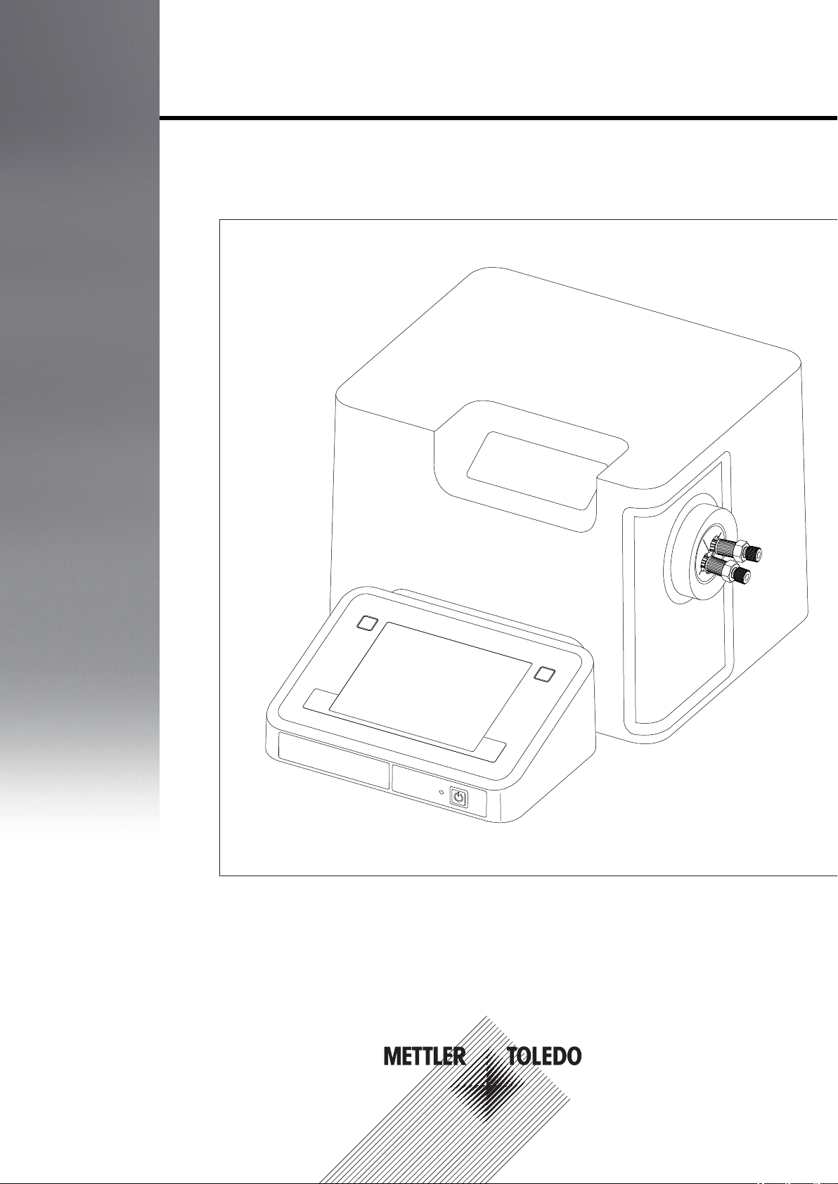
2Safety measures
These instruments have been tested for the applications documented in the appropriate operating instructions.
However, that does not absolve you of the responsibility to check for yourself the suitability of the products sup
plied by us for the procedures and purposes for which you intend to use them. You should therefore observe the
following safety measures.
Measures for your personal protection
Risk of electric
shock
Risk of explosion
Risk of corrosion
●
Ensure that you plug the supplied power cable into a socket that is grounded! In the
absence of grounding, a technical fault could be lethal.
●
Only use the power supply which was supplied with the device.
●
Never work in an environment subject to explosion hazards! The housing of the
instrument is not gas tight (explosion hazard due to spark formation, corrosion
caused by the ingress of gases).
●
Test highly combustible, poisonous or corrosive substances under an extractor
hood and follow the normal laboratory rules and precautions.
●
When using chemicals and solvents, comply with the manufacturer's instructions
and the general lab safety rules!
Measures for operating safety
●
Do not clean the measuring cell with conc. caustic soda (sodium hydroxide, NaOH)
or hydrofluoric acid (HF)! Both substances will chemically corrode the measuring
cell.
●
Caution
Exclude the following environmental influences:
- Direct sunlight
- Air humidity above 80%
- Ambient temperatures below 5 °C and above 35 °C
- Powerful electrical or magnetic fields capable of affecting the power supply due to
large load changes
- Strong vibrations
Only have the instrument serviced by an authorized METTLER TOLEDO Service agent!
6 Safety measures
Page 7
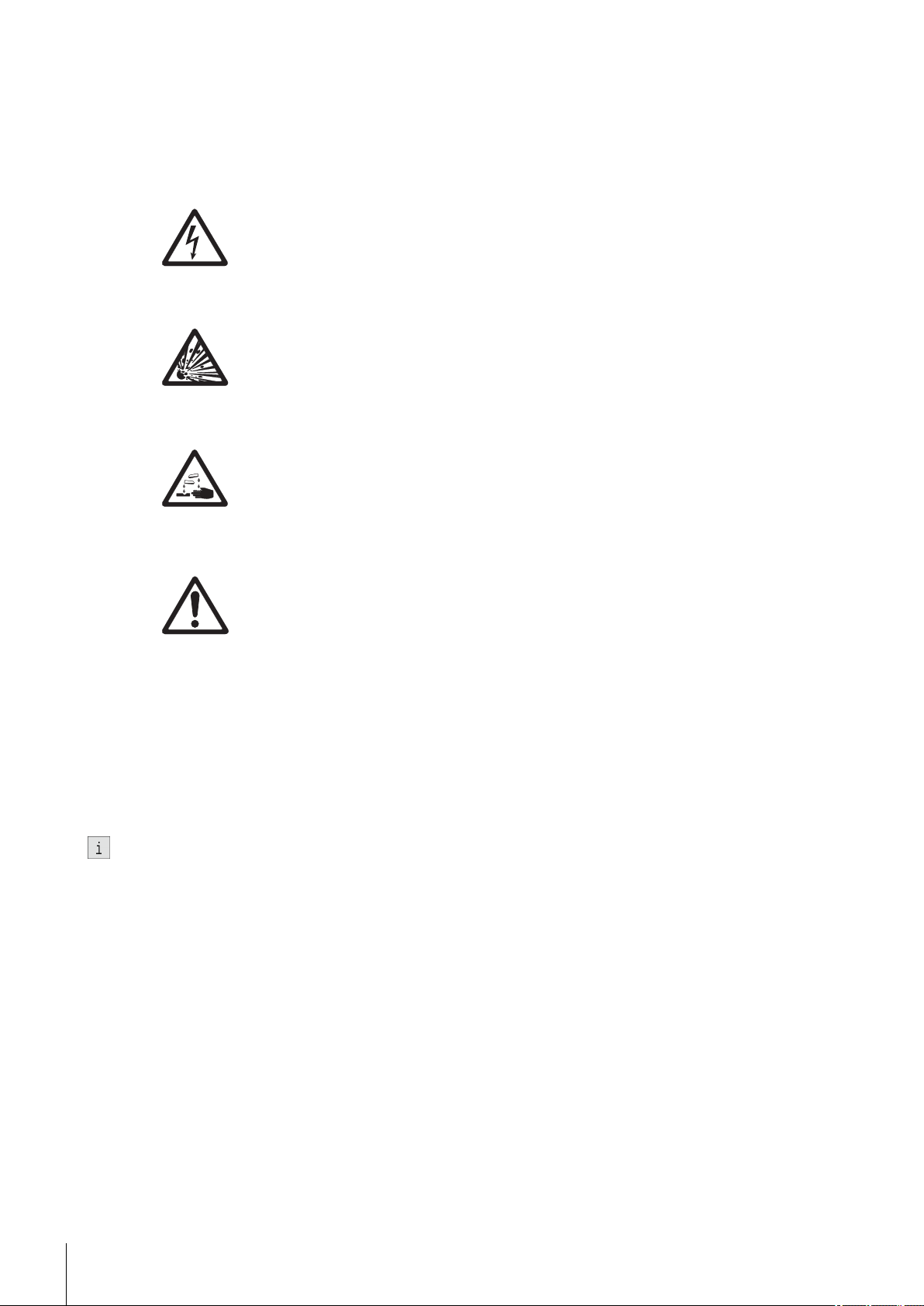
3Standard Equipment
All parts are specified with their ordering code and quantity in cases where more than one part is included.
Description Order number
Density Meter:
- DM40
- DM45 DeltaRange
- DM50
External power supply (100 – 240 Volt) 51192015
Power cable (country-specific) -
In use cover 51337079
51337000
51337001
51337002
Combination ring/open-ended wrench 51192087
Allen wrench 51192088
Disposable syringe (10mL)
(5 pcs.)
DM tube / syringe adaptor
(1 pc.)
51338100
51337154
7Standard Equipment
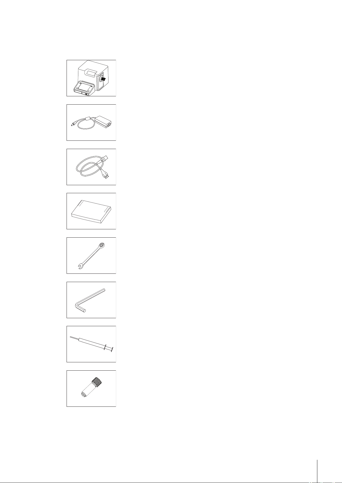
Page 8
Waste tube:
- M8 / 600 mm
Tubing:
- M8 / M8 / L280 mm
- M8 / M8 / L400 mm
Combined density / refractive index standard water (9mL) 51338010
51337223
51337224
51337226
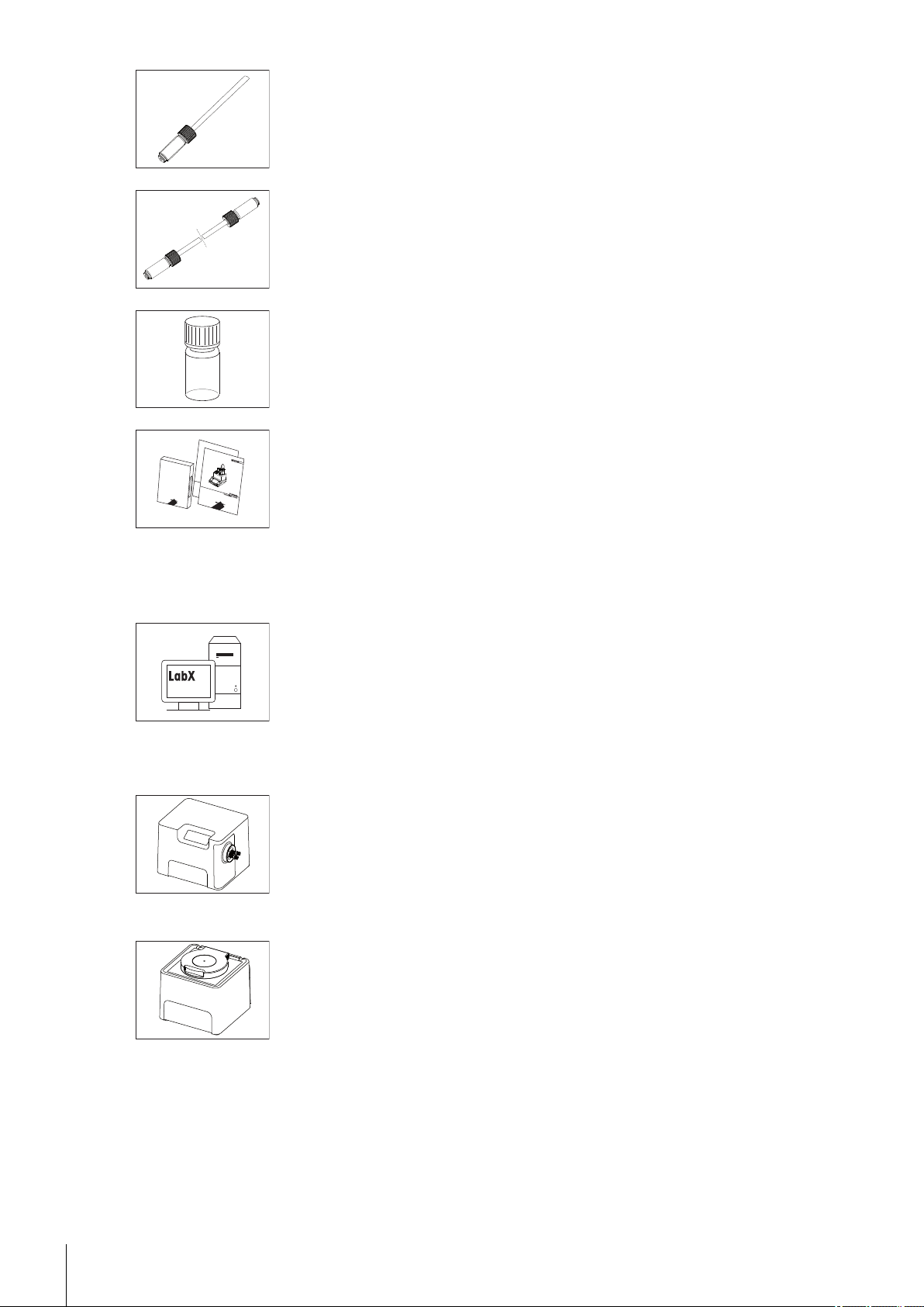
3.1Optional Accessories
Software
External measuring cells
Density modules:
DM40/45 DeltaRange/50 CD containing operating and instal
lation instructions
●
LabX (PC software for the instrument)
●
Device licenses for the instrument
- DX40
- DX45 DeltaRange
- DX50
51710776
LabX
51337005
51337006
51337007
Refractive index modules:
●
RM / RX flow cell with connecting set, incl.
- Tubing, M8 / M8 / L400
- Tubing, M8 / M8 / L550
- Tubing, M8 / L400
- O-ring for flow cell
- Protection plate
8 Standard Equipment
- RX40
- RX50
- RX fixing device (for securing the refractive index
module vertically)
51337008
51337009
51337025
51337024
51337226
51337227
51337223
51192068
51337189
Page 9
Automation
DryPal (drying pump) complete with
- desiccator
- silicon tube, D6/d3 L500
- silica gel
FillPal (sampling pumps):
- FillPal Food
- FillPal Chem
- Tubing set FillPalFood complete
- Tubing set FillPalChem complete
- Shielded sampling tube, L = 25 cm
- Tubing, M8 / M8 / L400
- Tubing, M8 / M8 / L550
●
SC1/SC30 automation units:
- SC1 (sample and cleaning unit)
- SC1H (heated version of SC1)
- SC30 (sample and cleaning unit for 30 samples)
- SC30H (heated version of SC30)
●
InMotion™ Autosampler
- Bundle: Flex Base with 100mL rack
51337029
51337180
51337228
51337241
51337027
51337028
51337219
51337218
51337236
51337226
51337227
51326000
51326400
51327000
51327500
30094290
- Flex Base
- Flex Rack Kit 25mL beaker (50 samples)
- Flex Rack Kit 80mL beaker (27 samples)
- Flex Rack Kit 100mL beaker (18 samples)
30094291
30094124
30094125
30094126
30094292
- Pro Base
- Pro Rack Kit 25mL beaker (182 samples)
- Pro Rack Kit 80mL beaker (69 samples)
30094129
30094130
30094131
- Pro Rack Kit 100mL beaker (34 samples)
30094293
- Max Base
- Max Rack Kit 25mL beaker (303 samples)
- Max Rack Kit 80mL beaker (113 samples)
30094134
30094135
30094136
- Max Rack Kit 100mL beaker (55 samples)
External instruments
●
SevenCompact S220 pH/Ion 30019028
●
pH connecting kit complete with
- Tubing, M8/M8 L400
- Tubing, M8/M8 L550
- Cable for pH electrode
- USB/RS adaptor for SevenEasy™ / SevenCompact™ pH meter
- RS-232C cable
- pH electrode
- External flow cell
51337023
51337226
51337227
59902392
51105851
51190589
59902917
51337190
51337197
- Holding plate for pH / Conductivity flow cell
●
SevenCompact S230 Conductivity 30019033
9Standard Equipment
Page 10

●
Conductivity connecting kit complete with
- Tubing, M8/M8 L400
- Tubing, M8/M8 L550
- USB-RS adaptor for SevenEasy™ / SevenCompact Conductivity™
- RS-232C cable
- Conductivity sensor
- External flow cell
- Holding plate for pH / Conductivity flow cell
51337022
51337226
51337227
51105852
51190589
51302885
51337190
51337197
Colorimeter
●
Color connecting kit Lovibond complete with
- Flow cell
- USB-RS adaptor for Lovibond colorimeter
51337021
51337295
51105853
The Lovibond Type PFX8XX, 9XX or PFXi8XX, 9XX colorimeter is obtainable from Tintometer AG.
●
Color connecting kit Konica Minolta complete with
- Flow cell
- USB A-B cable
30025477
51337295
51191926
The colorimeter Type CM-5 or CR-5 and the needed transmittance specimen holder is obtainable from Konica
Minolta.
Auxiliary Instruments
●
Adapter Auxiliary Instruments (USB-RS232 convertor) 51105856
Sensors
●
LevelSens (fluid level sensor for waste bottle, incl. attachment strap and 2m cable)
- Extension cable 1 m for LevelSens (optional)
●
WasteSens (fluid level sensor for waste bottle) inc.
- WasteSens holder
●
AtmoSens (atmosheric pressure sensor) 51337186
●
ErgoSens (motion sensor) 11132601
51109863
51108308
51337026
51337157
Peripherals
●
ScanStraight (built-in barcode reader) complete 51337185
●
Barcode reader (hand-held)
- USB cable for barcode reader
●
LogStraight (fingerprint reader) 51192107
●
Printer (USB-P25) inc. cable
- paper rolls (2 pcs.)
- ink ribbon (black)
21901297
21901309
11124301
12120799
12120798
10 Standard Equipment
USB data export box 51105855
Page 11

Miscellaneous accessories
●
Packing complete DM/DX 51337284
●
DM/DX transport lock set 51337164
●
Cell adaptor (PTFE) 51337158
●
Mounting tool cell adapter (used for mounting the cell adapter) 51337293
●
Protective sleeve (blue) 51337078
●
Coupling piece for M8 screws (set of 2) 51337179
●
Tubing, M8/M8 L280
●
Tubing, M8/M8 L400
●
Tubing, M8/M8 L550
●
Tubing, M8/M8 L800
51337224
51337226
51337227
51322234
11Standard Equipment
Page 12

4Layout of the Density Meters
A
B
C
D
E
F
4.1Front View
A: Connection for outlet tube
B: Connection for inlet tube
C: On/Off button
D: Indicator lamp
E: Touchscreen
F: Internal cell and viewing window
12 Layout of the Density Meters
Page 13

4.2Rear View
Connection Description
DryPal
pH/Cond
RX Socket for fixing plate for stabilizing the external RX refractometer cell
ErgoSens Connection for infrared motion sensor
WasteSens Connection for fluid level sensor (WasteSens/ LevelSens)
Aux Service connection
DryPal Connection for drying pump
FillPal Connection for sampling pump
Power Supply Power supply connection
Automation Connection for automation unit SC1 or SC30
Ethernet Network interface for LabX PC software, network export, network printer
PC USB interface for LabX PC software
Socket for:
●
DryPal (drying pump)
●
External flow cell: pH or conductivity
13Layout of the Density Meters
Page 14

Connection Description
USB 1/USB 2 For connection of various USB devices:
●
Density Module/Refractiv Index Module
●
InMotion™ Autosamplers
●
External instruments
●
Fingerprint reader
●
Barcode reader
●
USB-P25 printer
●
AtmoSens
●
USB memory stick
14 Layout of the Density Meters
Page 15

5Getting Started
a
a
a
a
a
a
a
a
The following sections describe how to connect the instrument, set it up and adjust it, and how to carry out the
first measurement.
5.1Removing Transport Lock and Connecting
Removing transport lock
After unpacking the device, the eight screws (a) on the underside of the unit must be removed before the instru
ment is connected electrically. To remove the screws, use the combination ring/open-ended wrench supplied.
When shipping or transporting the instrument over long distances, you should refit the transport screws and the
original packaging.
Connecting the power cable
Plug the power cable into the connection labeled "Power Supply" on the rear panel of the device. Switch on the
instrument so that it can adjust to operating temperature.
●
Connect the instrument only to a grounded power outlet socket.
●
Make sure it matches the instrument's power supply rating.
●
The power outlet socket must be easily accessible.
5.2Connecting Hardware
Connect your additional devices (e.g. printer, sensors, external measuring cells or automation units) to the
appropriate sockets on the rear panel of the density meters (see also "Layout of Density Meter: Rear view
(page13)").
●
For detailed information on the installation of such devices and the attachment of tubes to the automation
units and rinsing/waste reservoirs, please refer to the instruction manuals for the devices concerned.
●
When connecting PnP-compatible devices, the PnP parameters are automatically transferred to the instru
ment setup.
15Getting Started
Page 16

5.3Defining Setup Settings
This section briefly describes which hardware settings you should customize:
●
Connecting an SC1/SC30:
Navigation: Home > Setup > Hardware > Automation > SC1 or SC30
If you are connecting an SC1 or SC30 automation unit, in the setup you must specify the solvents that are
connected to the connections "Rinse 1" and "Rinse 2" on the SC1/SC30.
●
Connecting an InMotion autosampler
Navigation: Home > Setup > Hardware > Automation > InMotion
If you are connecting an InMotion autosampler, in the setup you must define on which port the sampling
pump is connected. Optionally also on which port the stirrer and/or PowerShower pump is connected.
●
Connecting a colorimeter:
Navigation: Home > Setup > Hardware > External instruments > Parameters
In addition to the device-specific information boxes, there are editable fields for entering the four wave
lengths for the colorimeter.
●
Connecting fingerprint reader:
Navigation: Home > Setup > Hardware > Peripherals > Fingerprint reader
If you are using a fingerprint reader, the parameter "Activate fingerprint reader" must be set.
●
Connecting ErgoSens/WasteSens:
Navigation: Home > Setup > Hardware > Sensors
If you are using these sensors, the parameters "Activate ErgoSens"/"Activate WasteSens" must be set.
●
Connecting barcode reader:
Navigation: Home > Setup > Hardware > Peripherals > Barcode reader >
Parameters
The format of the barcode must be defined as set out in the Operating Instructions.
●
Connecting auxiliary instruments:
Navigation: Home > Setup > Hardware > Auxiliary instruments
The auxiliary instruments must be defined as set out in the Operating Instructions.
5.4Global Settings
●
Entering device identification:
Home > Setup > Global settings > System > Identification
In the Instrument identification dialog box you can enter your own user-defined ID code in the text box for
the parameter "Instrument ID".
●
Setting date and time:
Navigation: Home > Setup > Global settings > System > Date/Time
●
Defining physical properties:
Navigation: Home > Setup > Global settings > Physical properties
- Select the desired unit for the parameter "Temperature unit".
- If you are not using an atmospheric pressure sensor (AtmoSens), enter the standard atmospheric pressure
for your location (elevation above sea level) according to the table below.
Note: If an AtmoSens is connected, the current atmospheric pressure is displayed and used.
16 Getting Started
Page 17

Density in relation to pressure
Height above sea level Atmospheric
[m] [feet] [hPa] [m] [feet] [hPa]
0 0 1013
100 328 1001 1400 4593 856
200 656 990 1500 4921 846
300 984 978 1600 5249 835
400 1312 966 1700 5577 825
500 1640 955 1800 5906 815
600 1969 943 1900 6234 805
700 2297 932 2000 6562 795
800 2625 921 2100 6890 785
900 2953 910 2200 7218 776
1000 3281 899 2300 7546 766
1100 3609 888 2400 7874 756
1200 3937 877 2500 8202 747
*)
Factory setting
5.5Care and Maintenance
Attaching an external measuring cell:
Navigation: Home > Setup > Mainten. & Service > Add external cell
Perform the action "Add external cell". In the Cell dialog box, the cell type must be selected (Home > Setup
> Hardware > Cell).
pressure
Height above sea level Atmospheric
pressure
*
1300 4265 867
5.6Cleaning the Measuring Cell
Before you adjust the device, the measuring cell must be cleaned. To do so, first rinse the cell with water and
then with acetone. When doing so, proceed as follows:
Manual operation
1 Attach the syringe adaptor to the lower measuring cell connection (inlet) (note: adaptor must be firmly seat
ed).
2 Make sure that the outlet tube feeds into a waste reservoir.
3 Clean the cell thoroughly several times using a syringe – first using a suitable cleaning agent (e.g. water)
and then with a mildly volatile solvent (e.g. acetone).
Note: If the cell is heavily soiled, other solvents such as Deconex (0.3%) must be used as well.
4 After the measuring cell has been cleaned it must be dried. For that purpose you should connect the outlet
tube to the DryPal drying tube.
5 In the Automation dialog, select the parameters "Action = Dry" and "Dry mode = Automatic" (Navigation:
Home > Manual > Automation).
6 Touch Start.
The drying process will start.
Note: The drying pump switches off automatically when the cell is dry. The drying process should be
completed in approx. 3 minutes.
Automatic operation
When using the instrument with a FillPal/SC1/SC30, the actions "Dry" and "Rinse" of the manual operation
"Automation" can be used.
For details, refer to the Operating Instructions, "Manual operations > Automation > Action: Dry/Action: Rinse"
17Getting Started
Page 18

See also
●
Rear View (page13)
5.7Adjusting the Measuring Cell
5.7.1Creating an Adjustment Method
Navigation: Home > Methods/Products > Methods
This section describes how to create an adjustment method.
You must define a suitable method for adjustment. In the Adjustments and Tests setup there is the adjustment
set "Air&Water20.00C". You can use that adjustment set for your first adjustment.
1 Touch the New button in the Methods dialog box.
The Method templates dialog box opens.
2 In the dialog box, touch the method template "ADJUSTMENT".
The Configuration dialog box appears.
3 Touch OK.
4 Touch the method function "Title".
5 In the "Method ID" parameter box, enter an ID.
6 Touch OK.
The parameters do not have to be changed for the subsequent method functions; the preset parameters
can be accepted.
7 Save the method.
5.7.2Performing Adjustment
Make sure that the measuring cell is clean and completely dry.
Switch on the device and wait for it to reach operating temperature, which will take at least 15 minutes in
the case of the DM40 and 30 minutes with the DM45 or DM50.
Note: Immediately after switching on, this adjustment is not correct for very long as the volume of the mea
suring cell's glass vessel changes slightly during the warming-up phase. Therefore, you should check regu
larly at the start of a series of measurements, e.g. by measuring the density of water, whether the instrument
is still measuring accurately. If you identify a systematic deviation, you should perform the adjustment
again. The DM40 should be completely stable after approx. 2 hours. With the 5-digit instruments (DM45
and DM50), it can take up to 48 hours.
1 Open the new adjustment method you defined at Home > Methods/Products > Methods.
2 Touch Start.
The Start analysis dialog box opens.
3 In the dialog box, touch Start.
The cell is adjusted according to the settings previously entered.
Manual method:
When the prompt "Add sample" appears, slowly inject water into the measuring cell with the aid of the syringe
and then confirm by pressing OK.
Operation with FillPal:
When the prompt "Immerse aspiration tube in sample" appears, place the aspiration tube in the sample beaker
and press OK to confirm.
Operation with SC1/SC30:
place the sample vial in the automation unit before starting adjustment.
Operation with InMotion Autosampler:
place a beaker with water in the rack before starting adjustment.
18 Getting Started
Page 19

●
In order to obtain a meaningful reading, the sample should run a minimum of approx. 15 cm out of the
measuring cell.
●
If you have a printer connected, a summary of the adjustment data is printed out at the end of the adjust
ment process.
See also
●
Cleaning the Measuring Cell (page17)
5.8Testing the Measuring Cell
The purpose of this test is to check that the device is fully functional. To be able to perform the test, you have to
create a test method.
This section describes how to create a test method and carry out the test.
5.8.1Creating a Test Method
Navigation: Home > Methods/Products > Methods
1 Touch the New button in the Methods dialog box.
The Method templates dialog box opens.
2 In the dialog box, touch the method template "TEST".
Note: The remaining procedure is analogous to that described in the section Creating an adjustment method
(page18).
3 Touch the method function "Test".
4 Set the parameter "Tolerance d" as follows:
DM40
Tolerance: 0.0002 g/cm3
DM45/50
Tolerance: 0.00004 g/cm
5 Save the method.
3
5.8.2Performing the Test
– Start the test method previously created.
A message will inform you whether the test succeeded or failed. If the test fails, you will be given sug
gestions for possible causes.
See also
●
Cleaning the Measuring Cell (page17)
●
Performing Adjustment (page18)
5.9Performing a Density Measurement
For the first measurement sequence, a simple measurement using water can be carried out.
5.9.1Creating a Measurement Method
This section describes how to create a measurement method.
1 Touch the New button in the Methods dialog box (Navigation: Home > Methods/Products >
Methods).
The Method templates dialog box opens.
2 Touch the method template "MEASURE" in the Method templates dialog box.
Note: The remaining procedure is analogous to that described in the section "Creating an adjustment
method (page18)".
19Getting Started
Page 20

5.9.2Performing the Measurement
Carry out the first measurement using water at 20°C by starting the method previously created.
See also
●
Cleaning the Measuring Cell (page17)
20 Getting Started
Page 21

6Technical Specifications
Density Meters DM40 / DM45 DeltaRange / DM50
Technical specifications of measuring cell
Measuring cell DM40 DM45 Delta Range DM50
Density
(Peltier)
Permanently stored concentration table
Alcohol
Viscosity correction Yes Yes Yes
Pressure range in the cell
Required sample volume at least 1.2 mL (manual injection with syringe)
Typical measuring times
(inc. thermostatic control)
Parts in contact with sample Borosilicate glass, PTFE, FEP, PP (syringe adaptor)
1)
Up to 100% by extrapolation
2)
measuring cell only
Technical specifications of hardware
Measuring range
[g/cm3]
Limits of error
[g/cm3]
Repeatability (SD)
[g/cm3]
Resolution
[g/cm3]
Range [°C] 0 - 91 0 - 91 0 - 91Temperature
Limits of error [°C] 0.05 (10 – 30)
Range [% v/v] 0 - 100 0 - 100 0 - 100
Limits of error
[% v/v]
Repeatability
(SD) [% v/v]
Range [% w/w] 0 - 83
Brix
Limits of error
[% w/w]
Repeatability
(SD) [% w/w]
Power supply
0 – 3 0 – 3 0 – 3
0.0001 0.00002
(d: 0.7 - 1)
0.00005
(d: 0 - 3)
0.00002
(d: 0 - 1)
0.00003
(d: 1 - 2)
0.00004
(d: 2 - 3)
0.00005 0.000005 0.000005
0.0001 0.00001 0.00001
0.1 (0 - 91)
0.02 (15 – 20)
0.05 (0 - 91)
0.02 (10 – 30)
0.05 (0 - 91)
0.1 0.02 0.02
0.1 0.01 0.01
1)
0 - 83
1)
0 - 83
1)
0.03 0.02 0.006
0.03 0.015 0.003
2)
up to 10 bar max.
at least 2 mL (complete cycle with attached automation unit)
approx. 1 to 4 minutes (manual)
approx. 2 to 10 minutes (complete cycle with attached automation
unit)
Input voltage 100–240 VAC ±10%
Input frequency 50–60 Hz
Primary connection socket 3 pin, IEC C14
Power consumption 120 VA
Connected load 24 VDC, 5 A
Secondary connection plug 4 pin, DC plug
Processor Marvel PXA270
CPU
312 MHz
SDRAM 64 MB
Flash memory 256 MB (industrial SD card)
21Technical Specifications
Page 22

Connections
Dimensions
Materials
Ambient conditions
ErgoSens Socket
Automation
PC PC connection via USB USB full speed
Display
Input Technology Full-coverage touchscreen
Width 272 mm (ex. cell connection)
Depth 385 mm
Height 215 mm
Weight 13.53 kg
Housing PP HCT540
Cover sheet PET
Protective cover Barex 201
Chassis Stainless steel
Inlet/outlet tube FLEXILON® PFA
Ambient temperature 5 °C - 35 °C
Relative humidity Max. 80% (non-condensing) at 31
°C, with linear reduction to 50% at
35°C
Use In interior spaces
Overvoltage category II
Pollution degree 2
Max. installation height 2000 m (above sea level)
3.5mm
(input for infrared sensor)
Socket 5-pin mini-DINWasteSens
Voltage 24 V DC ±5% (max. 1000 mA)
Socket 5-pin mini-DINAux
Voltage 24 V DC ±5% (max. 1000 mA)
Socket 5-pin mini-DINDryPal
Voltage 24 V DC ±5% (max. 1000 mA)
Socket 5-pin mini-DINFillPal
Voltage 24 V DC ±5% (max. 1000 mA)
Socket 9-pin male D-sub
Configuration Full-duplex
Baud rate 4800
Handshake X-On / X-Off
Galvanic isolation No
ESD stability Min. 1000 V
Short-circuit protection Yes
Socket RJ45Ethernet
Speed 10/100 MBit/s
USB host USB full speedUSB1 / USB2
Max. power load 400 mA
Technology Color TFT
Size 5.7"
Resolution 640 x 480 pixels
Backlighting LED
Brightness control Per software 50–100%
22 Technical Specifications
Page 23

7Maintenance and Service
Cleaning
Clean the casing of the instrument using a cloth moistened with alcohol.
The measuring cell is cleaned using the method function "Clean" (for details refer to "Cleaning the measuring
cell (page17)").
23Maintenance and Service
Page 24

8Disposal
In compliance with European Directive 2002/96/EC on Waste Electrical and Electronic
Equipment (WEEE), this instrument must not be disposed of together with domestic
waste. This also applies to countries outside the EU, per their specific requirements.
Please dispose of this product in accordance with local regulations at the collecting
point specified for electrical and electronic equipment.
If you have any questions, please contact the responsible authority or the distributor
from which you purchased this instrument.
Should this instrument be passed on to other parties (for private or professional use),
the content of this regulation must also be related.
Thank you for your contribution to environmental protection.
24 Disposal
Page 25

9Critical Errors
Error code Error
E007 Fan 1 stopped
E030 Fan 2 stopped
E028 Temperature sensor malfunction
E029 Thermomodule malfunction
E031 Hardware error
E033 Memory error
E064 Maximum temperature exceeded
E075 Electric current too high
E076 Voltage too high
25Critical Errors
Page 26

10Declaration of System Validation
Density Meters (DM40 / DM45 DeltaRange / DM50)
We hereby give notice that this product / system and its software and accessories were developed, tested and
successfully certified on the basis of the product life-cycle policies of Mettler-Toledo AG, Analytical. These poli
cies are based on ISO Standard 9001:2000. Life-cycle checkpoint details were reviewed and approved by the
Project Steering Group (PSG). The products / systems were tested in respect of functionality and specification
prior to shipment. In order to support GLP and validation requirements, we will make the following documents
available to authorized persons for inspection:
●
Performance specifications
●
Market and technical requirements
●
Quality plan
●
Project management system
●
Plan and Test results
●
Review reports
Mettler-Toledo AG, Analytical will retain possession of all documents and their reproductions and may wish to
conclude a nondisclosure agreement with those requesting access to these documents.
Schwerzenbach,
December 2011
Chris Radloff
General Manager
Business Unit Analytical
Christian Walter
Manager Business Area
AnaChem
26 Declaration of System Validation
Page 27

11Declaration of Conformity
27Declaration of Conformity
Page 28

28 Declaration of Conformity
Page 29

29Declaration of Conformity
Page 30

Page 31

Page 32

Mettler-Toledo AG, Analytical
CH-8603 Schwerzenbach, Switzerland
Tel. +41 (0)44 806 77 11
Fax +41 (0)44 806 73 50
www.mt.com
www.density.com
For more information
Subject to technical changes.
© Mettler-Toledo AG 03/2014
51710780C
*51710780*
 Loading...