

Page 1
Operating Instructions
METTLER TOLEDO
/
DL77
DL70ES
/
DL67 Titrators
S
E
L
RESET
S
E
L
EXIT
RUN
Page 2

Page 3

1. INSTALLATION
2. EDITOR
3. ANALYSIS
4. AUXILIARY FUNCTIONS
5. DOCUMENTATION
6. USER LEVEL
7. REMOTE CONTROL
8. Designations – Explanations – Examples
9. Error messages and malfunctions
10. Applications
11. Installation instructions, Technical data, Accessories
12. Index, Certificates & Declarations
Page 4

Page 5
Introduction
Safety measures
The titrators have been tested for the experiments and intended purposes documented in the
Tutorial and these Operating Instructions. However, this does not absolve you from the
responsibility of performing your own tests of the products supplied by us regarding their
suitability for the methods and purposes you intend to use them for. You should therefore
observe the following safety measures.
Measures for your protection
– Ensure that you plug the power cable supplied into a receptacle outlet that
is grounded! In the absence of grounding, a technical fault could be lethal.
– Switch the instrument off and disconnect the power cable before you open
Risk of electric
shock
the housin or change blown fuses! An electric shock could be lethal.
– Never work in an environment subject to explosion hazards! The housing
of the instrument is not gas tight (explosion hazard due to spark formation,
corrosion caused by the ingress of gases).
Risk of explosion
– Always test the titration vessel for firm seating in the titration head! If it falls
off, you could injure yourself if working with toxic titrants and solvents or
strong acids or bases.
Risk of corrosion
– When using chemicals and solvents, comply with the instructions of the
producer and the general lab safety rules! Additional safety precautions for
Karl Fischer titrations are described in Section 10.2.
Measures for operational safety
– Check the set operating voltage before you switch on the titrator (see
Section 11.1.5)! The instrument will be damaged if the operating voltage
does not match the line voltage.
Caution
– Use only fuses of the specified type if you need to change them!– Have
the instrument serviced only by METTLER TOLEDO Service!
– Always wipe off splashed liquids immediately! The instrument is not water-
proof.
– Exclude the following environmental influences:
• powerful vibrations,
• direct sunlight,
• atmospheric humidity greater than 80%,
• temperatures below 5 °C and above 40 °C,
• powerful electric or magnetic fields!
02/93 METTLER DL77/DL70ES/DL67 1
11/97
Page 6

Introduction
2
METTLER DL77/DL70ES/DL67
02/93
Page 7

Introduction
Introduction
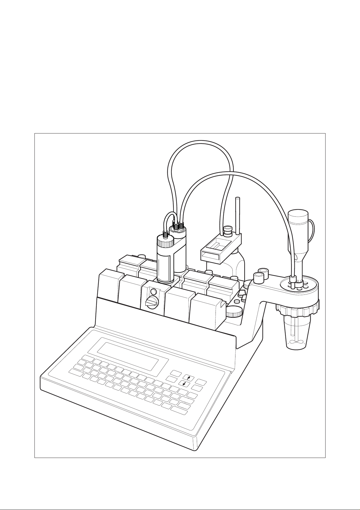
The DL77, DL70 ES, and DL67 METTLER titrators are microprocessor-controlled analytical
instruments that provide accurate and reproducible results thanks to their built-in intelligence.
With these titrators, you can perform end point, equivalence point and pH-stat titrations,
measure pH/mV and temperature, and determine TAN/TBN and p/m values. With the aid of
a polarization current source, you can determine water contents by the Karl Fischer method
(>2 mg H2O/sample). You can perform conductivity measurements and conductometric
titrations with an appropriate non-Mettler unit equipped with an analog output.
All titrators have a maximum of four inputs for electrodes, two for temperature sensors and
three 24-V outputs for stirrer, pump or valve attachments. They have a maximum of four
RS232C/CL interfaces, enabling you to connect a series of peripheral instuments:
- an attached METTLER balance transfers the sample weight automatically,
- a printer records the desired results,
- a color terminal serves as a second display and can be used for remote control, or a PC/robot
can interchange data with the titrator, and
- with an attached METTLER Sample Changer, each titrator is turned into a titration system
for the automatic analysis of whole series of samples.
How the three titrators differ from each other
DL77: Two titrations can be executed simultaneously and two sample changers can be
connected. Neither the DL70ES nor the DL67 allow this.
DL77/ These titrators can control a maximum of four burette drives, the DL67 two.
DL70ES:
These instruments know the most important titrants and all METTLER sensors,
whereas the DL67 knows one titrant and one sensor.
With both titrators a maximum of 10 titration methods can be entered in a list and
processed in succession. With the DL67 one method can be entered at a time.
While a titration is running, you can develop and save a new method, or you can
enter sample data for the next titration method. This is not possible with the DL67.
02/93 METTLER DL77/DL70ES/DL67 3
Page 8

Introduction
Operating concept
What information will you find where?
1. The TUTORIAL, provided with the standard equipment, will help you to overcome any
inhibitions you may have with regard to the new instrument. You will get to know the
function keys, the keypad and the display. Using a stored method for an acid-base titration,
you will perform your first analysis.
2. These Operating Instructions provide a complete description of the concept and oper-
ating characteristics of the three titrators.
The operating concept and a compilation of the key combinations follow this introduction.
3. The RS232C Interface Description, i.e., a detailed description of the communication bet-
ween titrator and computer, is provided with the standard equipment (since June, 1999).
Note: These Operating Instructions apply to software version 3.0 or 3.1.
The organization of the Operating Instructions
The organization is based on a modular principle. This allows supplementation or the interchange of individual sections or pages: new text sections carry the date of issue (in the footer
on every page).
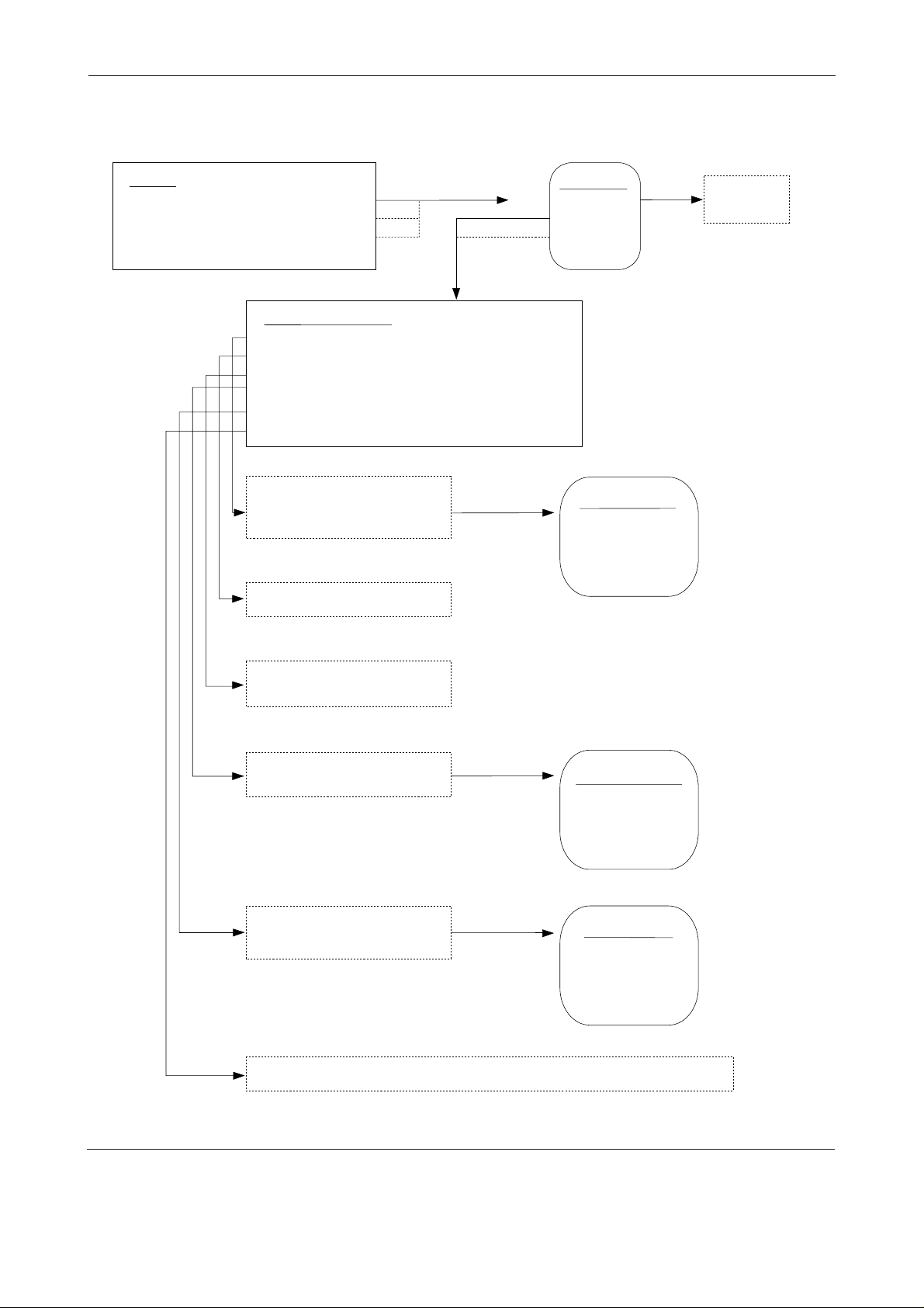
The operating concept of the titrator
The operation of the titrator is menu driven. What does this mean?
The titrator handles various tasks:
It stores, for instance, titrant names with the corresponding concentrations; it knows that it must
terminate the titration after an equivalence point has been found; it rinses burettes and can
provide records of stored data on an attached printer.
We call the listing of these various tasks a menu. Each task is subdivided further. If you select
a task from the main menu you are shown a new set of tasks – the submenu – from which you
can select another task. We refer to this as a menu tree when the main menu branches into
submenus and these in turn into additional submenus.
4
METTLER DL77/DL70ES/DL67
05/99
02/93
Page 9

Introduction
02/93 METTLER DL77/DL70ES/DL67 5
Page 10

Introduction
6
METTLER DL77/DL70ES/DL67
02/93
Page 11
Introduction
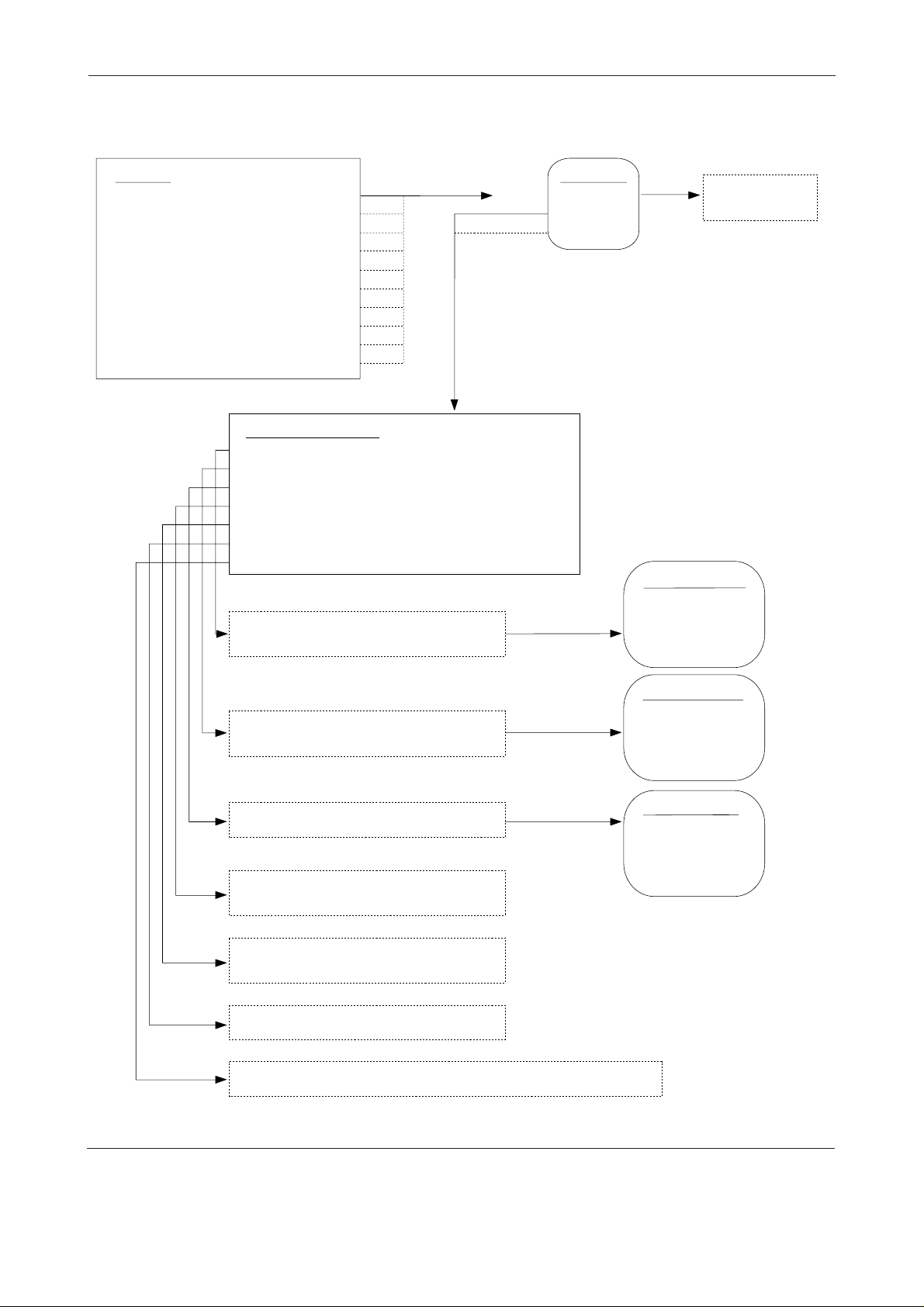
Key combinations
Rapid menu change with key combinations
In the Tutorial, you have already become acquainted with several key combinations which you
can employ to obtain a certain menu immediately. Using these keys, you can reduce the
number of keystrokes before and during the titrations considerably. The key combinations
consist of the index key and a letter key which must be pressed simultaneously. Key combinations exist to
• jump from a submenu into the main menu or from a submenu into that of another branch,
or to
• trigger commands for the burette or the printer (see below)
If you press a key combination in a submenu, the DL70 stores all changes that you have made
up to this point in the menu. The selector bar can be on any line of the menu.
Key combinations for commands
+
U
+
Y
+
L
+
P
+
C
Rinse burette (see Section 4.1.1)
Rinse tip (see Section 4.1.2)
Trigger line feed on the printer (see Section 1.8.1)
Trigger form feed on the printer (see Section 1.8.1)
The current display is printed (copied!)
Key combinations for menu change
MAIN MENU
INSTALLATION
EDITOR
+
M
ANAL YSIS A
ANALYSIS B*
AUXILIARY FUNCTIONS
DOCUMENTATION
USER LEVEL
REMOTE CONTROL
* only DL77
only if computer is installed
Installation
Titrants
Sensors
+
I
02/93 METTLER DL77/DL70ES/DL67 7
Temperature sensors
Auxiliary reagents
Auxiliary instruments
Auxiliary values
Titration stands
Peripherals
Miscellaneous
Page 12
Introduction
Key combinations
+
E
Editor
Method ID
METTLER methods
User methods
New method
+
A
Method
Method
+
B
Auxiliary functions
1 Burette
2 Stirrer
3 Sensor
+
F
+
D
4 Temperature
5 Sample changer
6 Auxiliary instrument
7 Calibration temperature sensors
8 Offset adjustment sensor inputs
Documentation
Print
Data transfer
Memory copy
Method
Add*
Method
Add
A
A
B
B
*DL67: Load
A: only DL77
only DL77
only if sample changer is installed
only if temperature option has been built in
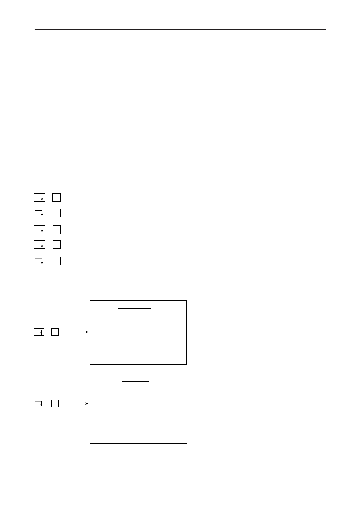
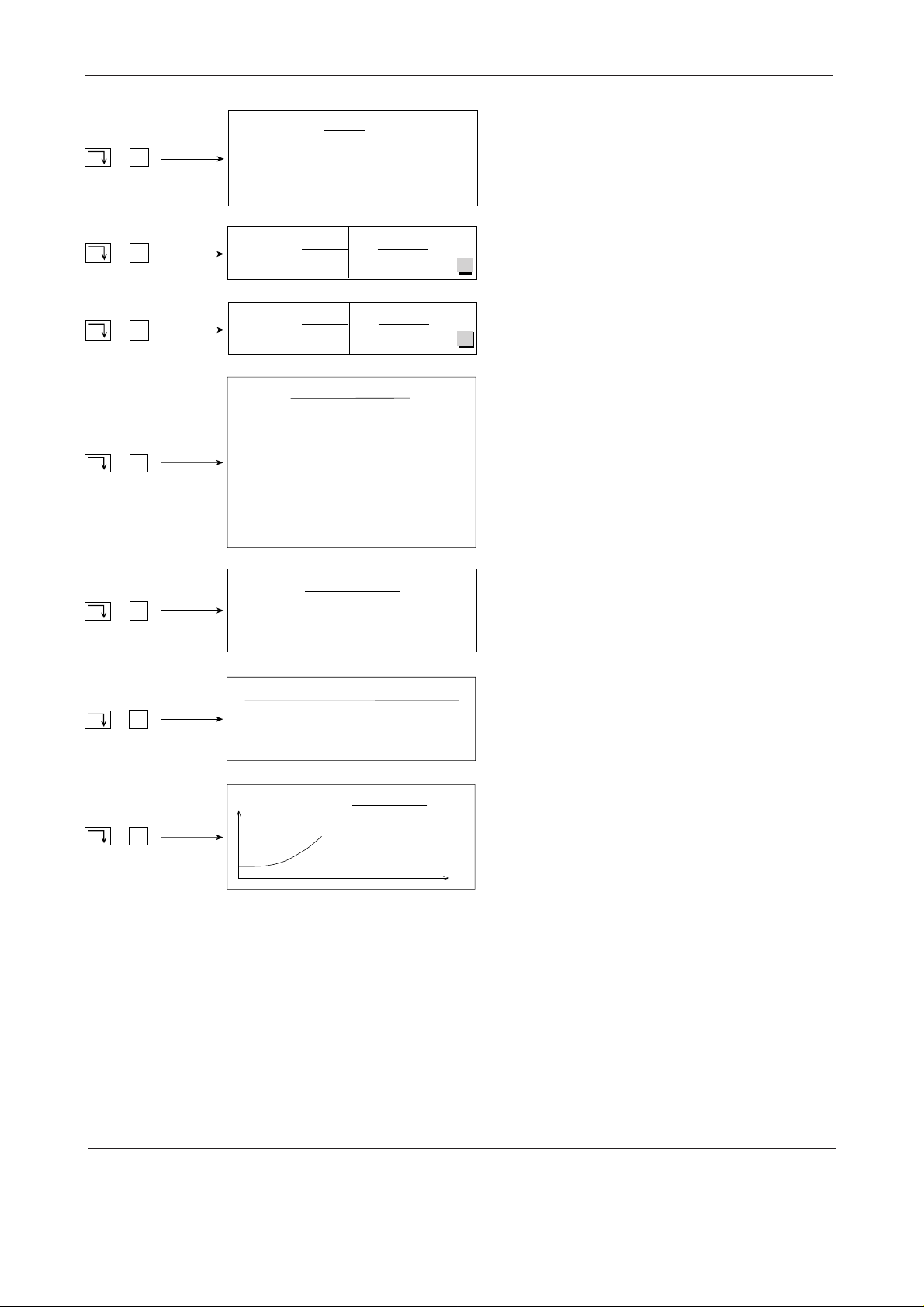
No. ID2 Wt./vol.
+
S
+
T
1/1
1/2
1/3
mV
0.0000 g
0.0000 g
0.0000 g
E –V curve
Sample data list for the current method
(example)
Display of the method function for the
current method (Titration function active)
mL
8
METTLER DL77/DL70ES/DL67
02/93
Page 13

INSTALLATION
INSTALLATION
Contents Page
1. INSTALLATION........................................................................................... 1-3
1.1 Titrants ........................................................................................................ 1-4
1.1.1 Delete........................................................................................................... 1-4
1.1.2 Modify........................................................................................................... 1-4
1.1.3 Add............................................................................................................... 1-8
1.2 Sensors ....................................................................................................... 1-9
1.2.1 Delete........................................................................................................... 1-10
1.2.2 Modify........................................................................................................... 1-10
1.2.3 Add............................................................................................................... 1-14
1.3 Temperature sensors................................................................................. 1-15
1.4 Auxiliary reagents ...................................................................................... 1-17
1.4.1 Delete........................................................................................................... 1-17
1.4.2 Modify........................................................................................................... 1-17
1.4.3 Add............................................................................................................... 1-18
1.5 Auxiliary instruments ................................................................................ 1-20
1.5.1 Delete........................................................................................................... 1-20
1.5.2 Modify........................................................................................................... 1-20
1.5.3 Add............................................................................................................... 1-21
1.6 Auxiliary values.......................................................................................... 1-23
1.7 Titration stands .......................................................................................... 1-25
1.8 Peripherals.................................................................................................. 1-28
1.8.1 Printer........................................................................................................... 1-28
1.8.2 Balance ........................................................................................................ 1-30
1.8.3 System ......................................................................................................... 1-32
1.8.4 Sample changer ........................................................................................... 1-35
02/93 METTLER DL77/DL70ES/DL67 1-1
Page 14

INSTALLATION
INSTALLATION
Page
1.9 Miscellaneous............................................................................................. 1-36
1.9.1 Format date/time .......................................................................................... 1-36
1.9.2 Enter date/time ............................................................................................. 1-36
1.9.3 Language ..................................................................................................... 1-37
1.9.4 Record header ............................................................................................. 1-37
1.9.5 Titrator ID ..................................................................................................... 1-37
1.9.6 Routine level ................................................................................................ 1-38
1.9.7 Audio signal.................................................................................................. 1-39
1.9.8 Analysis parameters..................................................................................... 1-40
1-2
METTLER DL77/DL70ES/DL67
02/93
Page 15

INSTALLATION
INSTALLATION
1. INSTALLATION
In order to perform titrations the titrator must be acquainted with the titrants and their
concentration, the sensors with their possible unit of measurement, and the solvents that it can
dispense by means of pumps. It must know the burette drive on which the burette is located,
the input to which the sensor is connected and what output carries the stirrer. It needs the
names of the attached units such as a balance or printer in order to transfer data. In this menu
you enter and store the names of all chemical and mechanical resources: you install them.
The most common titrants, solvents and all METTLER sensors are already installed in the
titrator. Not only can you delete these resources or modify their parameters, but you also have
the possibility to install new ones.
List of resources Titrants
Sensors
Temperature sensors
Auxiliary reagents
Auxiliary instruments
Auxiliary values
Titration stands
Peripherals
Miscellaneous
Caution: All resources needed for the METTLER methods stored in the application data
base are installed accordingly. If you delete one of these, the titrator will wait until
start of titration of a METTLER method before outputting the error message that the
resource is not installed.
DL67: Only the titrant and the sensor for METTLER method M001 are stored in the DL67.
02/93 METTLER DL77/DL70ES/DL67 1-3
Page 16

Titrants
INSTALLATION
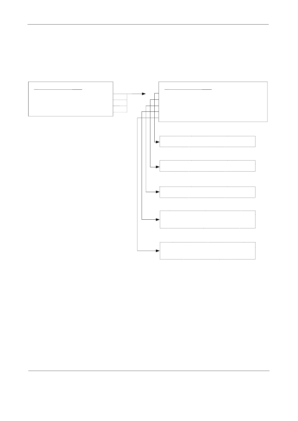
1.1 Titrants
When you select this menu you receive the installed titrants with the specified parameters
concentration and burette drive. (You will find the menu tree depicted at the end of Section
1.1.2.)
NaOH 0.1 mol/L Drive 3
HCl
HClO
4
etc...
DL67: The DL67 only has stored the titrant NaOH. You can, however, add titrants to the list
(see Section 1.1.3).
If you select, for instance, NaOH the list will be masked on the right by a selection menu
containing the following commands:
0.1 mol/L Drive 3
0.1 mol/L Drive 3
Delete
Modify
Add
1.1.1 Delete
Position the selector bar on this command and confirm with RUN. The mask of the selection
menu disappears, the titrant NaOH is deleted.
Note: You can also delete a titrant directly from the list by pressing the <–> (minus) key. You
can reinstall NaOH with the command Add (see Section 1.1.3).
1.1.2 Modify
If you select this command you are shown the parameter mask of the titrant (see next page).
If you move the selector bar to one of these parameters you can modify its name or value.
Note: a. Default values are stored in the titrator for all parameters, e.g. for the concentration
of the titrant 0.1 mol/L, for the titer 1.0.
1-4
• These values will be overwritten once you have entered new ones.
• If you want to modify only one digit of a value, you must first indicate the digit with
the cursor (with → or ←) prior to entering the new one.
METTLER DL77/DL70ES/DL67
02/93
Page 17

INSTALLATION
Titrants
Note: b. With many parameters the titrator has selection or recommendation menus in which
you need only select the values or names. If a parameter has one of these menus,
each time it is selected an arrow symbol (➡) appears at the extreme right in the
middle of the display. You can either accept the value or name following the
parameter or:
in the case of Recommendation,
– overwrite directly with a new entry or
– press SEL to select a new value or name from the recommendation menu that
appears.
in the case of Selection,
– press SEL to select a new value or name from the selection menu that appears.
You cannot enter the value or name yourself.
If only two names or values are possible for a parameter, these are toggled
automatically with SEL.
Name NaOH
Concentration [mol
/L]
0.1
Titer 1.0
Burette volume 10 mL
Burette drive Drive 3
Date/time (e.g.: 07–06–1992 12:20)
1. You can overwrite the name or press SEL to call up the recommendation menu:
Recommendation menu: You can select a new titrant from the recommendation menu.
Position the selector bar on, for instance, HCl and confirm with RUN. The recommendation
menu disappears and HCl follows Name.
2. Enter the concentration [mol/L]
3. Enter the titer only if you know its value. If you determine the titer of the titrant with the
titrator, its value is entered here together with the date automatically (see
Titer
function,
Section 2.3.16).
4. Select the burette volume from the selection menu:
Selection menu: You press SEL, position the selector bar on, for instance, 5 mL in the
selection menu and confirm with RUN. The selection menu disappears and 5 mL now
follows burette volume.
5. Select the burette drive from the selection menu.
02/93 METTLER DL77/DL70ES/DL67 1-5
Page 18

Titrants
INSTALLATION
DL67: It is only possible to select one of two burette drives for this titrator. If more than two
drives have been installed, the titrator will recognize each of the first two (counting from
left to right).
6. You can neither delete nor overwrite the date. It refers to the titer determination of the titrant
using the method function
(see
Titer
function, Section 2.3.16).
Titer
and is entered here together with the time automatically
Note: As soon as you change a titrant parameter, the date and time are deleted.
The titrant with the modified parameters is installed when you quit the parameter mask with
EXIT. Here, the selector bar can be positioned on any parameter, but not on the title line.If you
confirm the title line with EXIT the following selection menu appears:
Save modifications?
Yes
No
If you confirm "Yes" with RUN, the titrator stores the modified values or names.
If you confirm "No" with RUN, the old values remain in force.
Note: If you press a key combination (<index + letter>) to quit the Installation menu, the
modified parameters are stored automatically if the selector bar is positioned on a
parameter line. If it is positioned on the title line, the selection menu "Save modifications?"
appears again (see above).
1-6
METTLER DL77/DL70ES/DL67
02/93
Page 19
INSTALLATION
Menu tree
Titrants
Titrant
NaOH
HCl
HClO
etc.
Selection
0.1 mol/L
0.1 mol/L
4
0.1 mol/L
Drive 3
Drive 3
Drive 3
Delete
Modify
Add
The titrant
is deleted
Titrant parameters
Name
Concentration [mol/L]
Titer
Burette volume
Burette drive
Date/time
Enter new name or select
entry from recommendation
menu with SEL
Enter new concentration
NaOH
0.1
1.0
10 mL
Drive 3
(07-06-1992 12:20)
Titrant names
NaOH
HCl
HClO
4
etc.
Enter new titer or let it be
entered through titration
Select another burette
with SEL
Burette volume
1 mL
5 mL
10 mL
20 mL
Select another drive
with SEL
Burette drive
Drive 1
Drive 2
Drive 3
Drive 4
Date/time is entered only through titer determination by the titrator!
02/93 METTLER DL77/DL70ES/DL67 1-7
Page 20

Titrants
INSTALLATION
1.1.3 Add
Select this command if you wish to add a titrant to the titrant list, for instance NaOH of
concentration 1.0 mol/L or with a different burette volume, or a new titrant. You can also add
a titrant directly to the list by pressing the <+> (plus) key. You are always shown the following
mask:
Name NaOH
Concentration [mol
/L]
0.1
Titer 1.0
Burette volume 10 mL
Burette drive Drive 3
Date/time 00–00–0000 00:00
1. Select the titrant from the recommendation menu or enter the one you wish to install.
Note: If you install, for example, several NaOH solutions of the same concentration, you must
provide each name with a different flag to allow the titrator to distinguish between them,
e.g. NaOH/1.
2. Enter the concentration [mol/L].
3. Enter the titer only if you know its value. If you determine the titer with the titrator, its value
together with the date is entered here automatically (see
Titer
function, Section 2.3.16).
4. Select the burette volume from the selection menu.
5. Select the burette drive from the selection menu.
6. The date together with the time for the newly installed titrant is entered here automatically
only after the titer has been determined (see
Titer
function, Section 2.3.16).
The titrant with the appropriate parameters is installed when you quit the parameter mask with
EXIT (see the appropriate description at the end of Section 1.1.2).
1-8
METTLER DL77/DL70ES/DL67
02/93
Page 21

INSTALLATION
Sensors
1.2 Sensors
When you select this menu you are shown the installed sensors with the specified parameters
unit of measurement and the sensor input. (You will find the menu tree depicted at the end of
Section 1.2.2.)
DG111-SC pH Sensor 1 (Combined pH electrode – aqueous medium)
DG101–SC pH Sensor 1 (Combined pH electrode for small volumes in a
small titration vessel – aqueous medium)
DG113–SC mV Sensor 1 (Combined glass electrode with movable sleeve
frit – nonaqueous medium)
DG114–SC mV Sensor 1 (Combined glass electrode with movable sleeve
frit – aqueous medium)
DG115–SC mV Sensor 1 (Combined glass electrode with sleeve frit –
aqueous medium)
DM140–SC mV Sensor 2 (Combined platinum ring electrode – redox
titrations)
DM141–SC mV Sensor 2 (Combined silver ring electrode – argentometry)
DM142 mV Sensor 1 (Double-pin platinum electrode – voltametry)
DP550 % T Sensor 2 (Phototrode – transmission measurements at
550 nm)
DP660 % T Sensor 2 (Phototrode – transmission measurements at
660 nm)
DL67: Only sensor DG111-SC is stored in the DL67. You can, however, add sensors to the
list (see Section 1.2.3).
Note: There is no need to install a reference electrode as it is part of the installed measuring
electrode at input sensor 1. The input for the reference electrode is marked (see Section 11.1.4).
If you select DG111-SC, for instance, the list is masked on the right by a selection menu
containing the following commands:
Delete
Modify
Add
02/93 METTLER DL77/DL70ES/DL67 1-9
Page 22

Sensors
INSTALLATION
1.2.1 Delete
Position the selector bar on this command and confirm with RUN. The mask of the selection
menu disappears, the DG111-SC sensor is deleted.
Note: You can also delete a sensor directly from the list by pressing the <–> (minus) key. You
can reinstall the DG111-SC with the Add command (see Section 1.2.3).
1.2.2 Modify
If you select this command you are shown the parameter mask of the sensor in which you can
change the parameter values:
Name DG111-SC
Unit of measurement pH
Sensor input Sensor 1
Zero point [Unit] 7.0
Slope [mV/Unit] –59.16
Temperature [°C] 25.0
Date/time (e.g.: 02–06–1992 10:15)
1. Select the sensor name from the recommendation menu or enter the one you wish to install
in place of the DG111-SC sensor.
2. Select the unit of measurement suitable for the sensor from the selection menu. Within a
method you can later again choose between the selected unit of measurement and "mV"
in the functions Measure, Titration and pH/mV-stat (see Section 2.3.4/ 12/13).
mV: Either there is no other unit of measurement suitable for the sensor, or you
require only mV.
If you select the unit mV for a sensor, the calibration parameters zero point,
slope and temperature are ignored by the titrator.
pH: After you select pH you then enter the calibration parameters for a pH electrode
or you let the titrator do it (see notes a. and b. on page 1-12).
pM: M represents any cation. After you select pM you then enter the calibration
parameters for a pM electrode or you let the titrator do it (see notes a. and b.
on page 1-12).
pX: X represents any anion. After you select pX you then enter the calibration
parameters for a pX electrode or you let the titrator do it (see notes a. and b.
on page 1-12).
1-10
METTLER DL77/DL70ES/DL67
02/93
Page 23

INSTALLATION
Sensors
%T: After you select %T you then enter the calibration parameters of a phototrode
(unit of measurement: transmission, see
Operating Instructions "Phototrode"
A: After you select A you then enter the calibration parameters of a phototrode
(unit of measurement: transmission. The absorption (A = -log T) is calculated,
see
Operating Instructions "Phototrode"
).
µS/cm: After you select µS/cm you then enter the calibration parameters of the conduc-
tivity cell.
mS/cm: After you select mS/cm you then enter the calibration parameters of the conduc-
tivity cell.
Note: Conductivity measurements and conductivity titrations can be performed using a
conductometer equipped with an analog output.
3. Select the sensor input from the selection menu.
).
Notes: a. In the standard configuration of the titrator you have the sensor 1 and sensor 2 input
available. You should select the sensor 1 input for all glass electrodes as this has
the highest input resistance (see
Technical data
, Section 11.2.1)
Rear view of the titrator
.
, Section 11.1.4 and
b. For technical reasons, only the "low resistance" sensor input 2 may be selected for
phototrodes (see
Section 11.2.1)
Rear view of the titrator
.
, Section 11.1.4 and
Technical data
Caution: The RS option has an additional "low resistance" sensor input, the temperature
option an additional high resistance sensor input (see Sections 11.1.6 and 11.1.7).
Depending on the installation manner, the "low resistance" input may, for example,
be either sensor 3 or sensor 4! (See
Technical data
, Section 11.2.1).
Rear view of the titrator,
Section 11.1.4 and
4. Enter the zero point of the sensor:
The zero point of a sensor is the measured value at which it displays 0 mV potential (zero
point of electrode assembly).
• For the zero point of a pH electrode this is pH0 with unit pH.
,
• For the zero point of an ion-selective electrode this is pM0 with the unit pM, or pX0 with
the unit pX.
• The zero point of the phototrode is normally 0% T (100% T = 1000 mV).
• The zero point of a conductivity cell is normally 0 µS/cm or 0 mS/cm.
02/93 METTLER DL77/DL70ES/DL67 1-11
Page 24

Sensors
INSTALLATION
5. Enter the slope of the sensor.
The slope of a sensor is the potential change in mV per unit of measurement.
• For the slope of a pH electrode the unit is: mV/pH.
• For the slope of an ion-selective electrode the unit is: mV/pM or mV/pX.
• The slope of a phototrode is normally 10 mV/ %T.
• For the slope of a conductivity cell the unit is: mV/µS*cm
-1
or mV/mS*cm-1.
6. Enter the temperature: The actual calibration temperature is either
• defined by you when starting a calibration method (see Section 3.1) or
• measured automatically if you have attached and installed a temperature sensor (see
Sections 1.3, 2.3.2 and 2.3.17).
7. You can neither delete nor overwrite the date. It refers to the calibration of the sensor using
the method function
(see
Calibration
Calibration
and is entered here together with the time automatically
function, Section 2.3.17).
Notes: a. The calibration parameter values of the titrator installed in the factory are theoretical
values for a new sensor. You have to perform a calibration of your sensor if you wish
to determine accurate values (see
Calibration
function, Section 2.3.17).
b. When a pH, pM or pX sensor is calibrated the calibration parameters (zero point,
slope, temperature) are entered here automatically.
c. As soon as you change a sensor parameter, the date and time are deleted.
Caution: Do not transfer the calibration data obtained for glass electrodes attached to sensor
input 1 (or for the temperature option sensor input) to the electrodes you attach to
sensor input 2 (or the sensor input of the RS option)! Recalibrate these sensors to
obtain correct values!
The sensor with the modified parameters is installed when you quit the parameter mask with
EXIT (see the appropriate description at the end of Section 1.1.2).
1-12
METTLER DL77/DL70ES/DL67
02/93
Page 25
INSTALLATION
Menu tree
Sensors
Sensors
DG111-SC
DG101-SC
DG113-SC
DG114-SC
DG115-SC
DM140-SC
DM141-SC
DM142
DP550
DP660
pH
pH
mV
mV
mV
mV
mV
mV
%T
%T
Sensor 1
Sensor 1
Sensor 1
Sensor 1
Sensor 1
Sensor 2
Sensor 2
Sensor 1
Sensor 2
Sensor 2
Sensor parameters
Name
Unit of measurement
Sensor input
Zero point [unit]
Slope [mV/unit]
Temperature [°C]
Date/time
Enter new name or select entry from
recommendation menu with SEL
DG111-SC
pH
Sensor 1
7.0
-59.16
25.0
(02-06-1992 10:15)
Selection
Delete
Modify
Add
The sensor is
deleted
Sensor names
DG111-SC
DG101-SC
DG113-SC
etc.
Select another unit of measurement
with SEL
Select another input with SEL
Enter new zero point or let it be
entered through calibration
Enter new slope or let it be entered
through calibration
Enter new temperature
Date/time is entered only through calibration by the titrator!
Units of meas.
mV
pH
pM
etc.
Sensor inputs
Sensor 1
Sensor 2
Sensor 3
Sensor 4
02/93 METTLER DL77/DL70ES/DL67 1-13
Page 26

Sensors
INSTALLATION
1.2.3 Add
Select this command if you wish to add a sensor to the sensor list, for instance a
DG111-SC sensor with different calibration parameters or a sensor not yet installed. You can
also add a sensor directly to the list by pressing the <+> (plus) key. You are always shown the
following mask:
Name DG111-SC
Unit of measurement mV
Sensor input Sensor 1
Zero point [Unit] 7.0
Slope [mV/Unit] –59.16
Temperature [°C] 25.0
Date/time 00–00–0000 00:00
1. Select the sensor name from the recommendation menu or enter the name of the sensor
you wish to install.
Note: If you install, for example, several DG111-SC sensors, you must provide each name
with a different flag to allow the titrator to distinguish between them, e.g. DG111/2.
2. Select the unit of measurement suitable for the sensor from the selection menu.
3. Select the sensor input from the selection menu.
4. Enter the zero point of the sensor.
5. Enter the slope of the sensor.
6. Enter the temperature.
(see explanation of the parameters and note under
Modify
).
7. The date together with the time for the newly installed sensor is entered here automatically
only after the sensor has been calibrated (see
Calibration
function, Section 2.3.17).
The sensor with the appropriate parameters is installed when you quit the parameter mask with
EXIT (see the appropriate description at the end of Section 1.1.2).
1-14
METTLER DL77/DL70ES/DL67
02/93
Page 27

INSTALLATION
Temperature sensors
1.3 Temperature sensors
When you select this menu you are shown the installed temperature sensors with the specified
parameters sensor type and sensor unit:
TEMP A Pt100 Temp 1
TEMP B Pt100 Temp 2
TEMP C Pt1000 Temp 1
TEMP D Pt1000 Temp 2
You can neither delete a temperature sensor nor add a new one to the list. You can, however,
install several Pt100 or Pt1000 at the same temperature sensor input (Temp 1 or Temp 2), for
example.
If you select TEMP A, for instance, you are shown the parameter mask of the Pt sensor in which
you can change the parameter values or names:
Name TEMP A
Sensor type Pt100
Sensor input Temp 1
Zero point [°C] 0.0
Date/Time 00–00–0000 00:00
1. You can not change the sensor name: The line will be skipped when the selector bar is
moved.
2. Select the sensor type with SEL: "Pt100" or "Pt1000" (see Section 11.1.7).
3. Select the sensor input with SEL: "Temp 1" or "Temp 2" (see Section 11.1.4).
4. Enter the zero point of the Pt sensor.
The zero point of a Pt sensor is the deviation of a measured value from a reference value,
such as 0 °C for an ice bath.
5. You can neither delete nor overwrite the date. It refers to the calibration of the Pt sensor
using the auxiliary function
Calibration temperature sensors
and is entered here together
with the time automatically (see Section 4.7).
Notes: a. The installed zero point is the theoretical value for a new Pt sensor. You have to
perform a calibration of your sensor if you wish to determine an accurate value.
When calibrating, the zero point is automatically entered here together with the date
(see auxiliary function
Calibration temperature sensors
, Section 4.7).
b. As soon as you change a parameter of the temperature sensor, the date and time
are deleted.
02/93 METTLER DL77/DL70ES/DL67 1-15
Page 28
Temperature sensors
INSTALLATION
The Pt sensor with the modified parameters is installed when you quit the parameter mask with
EXIT (see the appropriate description at the end of Section 1.1.2).
Menu tree
Temperature sensors
TEMP A
TEMP B
TEMP C
TEMP D
Pt100
Pt100
Pt1000
Pt1000
Temp 1
Temp 2
Temp 1
Temp 2
Temperature sensors
Name
Sensor type
Sensor input
Zero point [°C]
Date/time
The name cannot be changed
Select the other type with SEL: Pt1000
Select the other input with SEL: Temp 2
Enter new zero point or let it be entered
through calibration!
TEMP A
Pt100
Temp 1
0
00-00-0000 00:00
1-16
Date/time is entered only through
zero-point calibration by the titrator
METTLER DL77/DL70ES/DL67
02/93
Page 29

INSTALLATION
Auxiliary reagents
1.4 Auxiliary reagents
When you select this menu you receive the installed auxiliary reagents with the specified
parameters dispensing rate and auxiliary output. An auxiliary reagent is a solvent that is
dispensed using a time-controlled device, e.g. a diaphragm pump or an electromagnetic valve.
(You will find the representation of the menu tree at the end of Section 1.4.3).
H2O 250 mL/min Aux.2
CH3OH 250 mL/min Aux.2
CHCl
3
etc.
DL67: Only auxiliary reagent H2O is stored in the DL67. You can, however, add auxiliary rea-
gents to the the list (see Section 1.4.3).
If you select H2O, for instance, the list is masked on the right by a selection menu containing
the following commands:
250 mL/min Aux.2
Delete
Modify
Add
1.4.1 Delete
Position the selector bar on this command and confirm with RUN. The mask of the selection
menu disappears, the auxiliary reagent H2O is deleted.
Note: You can also delete an auxiliary reagent directly from the list by pressing the <–> (minus)
key. You can reinstall H2O with the command Add (see Section 1.4.3).
1.4.2 Modify
If you select this command you are shown the parameter mask of the auxiliary reagent in which
you can change the parameter values:
Name H2O
Dispensing rate [mL/min] 250
Auxiliary output Aux.2
1. Select the name of the auxiliary reagent from the recommendation menu or enter the name
of the reagent you wish to install in place of H2O.
02/93 METTLER DL77/DL70ES/DL67 1-17
Page 30

Auxiliary reagents
INSTALLATION
2. Enter the dispensing rate [mL/min] of the device.
Notes: a. The titrator uses the dispensing rate to calculate the volume to be dispensed for
time-controlled pumps or electromagnetic valves (see functions Pump and Rinse,
Sections 2.3.8 and 2.3.9).
b. The dispensing rate of each device must be determined experimentally in advance
for each solvent:
– Add the particular solvent using the dispensing device to a measuring cylinder
within 1 minute (stopwatch) and note the volume.
– Repeat this procedure for, e.g. periods of 20, 30 and 40 seconds.
– Use the different volumes to calculate the mean value per minute and enter this
value.
3. Select the auxiliary output from the selection menu.
Note: The titrator has three auxiliary outputs (Aux. 1, 2 and 3). One auxiliary output of the
titrator is normally assigned to the stirrer, e.g. Aux. 1 (see Section 1.7). You should thus
select only Aux. 2 and/or Aux. 3 for this auxiliary reagent (see
Technical data
, Section
11.2.2).
If you have attached the sample changer (ST20A or ST20), this unit offers you two additional outputs called "RINSE" and "DOSE".
The auxiliary reagent with the modified parameters is installed when you quit the parameter
mask with EXIT (see the appropriate description at the end of Section 1.1.2).
1.4.3 Add
Select this command when you wish to add an auxiliary reagent to the list. You can also add
an auxiliary reagent directly to the list by pressing the <+> (plus) key. You are always shown
the following mask:
Name H2O
Dispensing rate [mL/min] 250
Auxiliary output Aux.2
1. Select the name from the recommendation menu or enter the reagent you wish to install.
Note: If you install several auxiliary reagents with the same name, you must provide each one
with a different flag to allow the titrator to distinguish between them, e.g. H2O/2.
2. Enter the dispensing rate [mL/min] of the device.
1-18
METTLER DL77/DL70ES/DL67
02/93
Page 31

INSTALLATION
Auxiliary reagents
3. Select the auxiliary output from the selection menu.
The auxiliary reagent with the appropriate parameters is installed when you quit the parameter
mask with EXIT (see the appropriate description at the end of Section 1.1.2).
Menu tree
Auxiliary reagents
H
O
2
CH
3
CHCl
OH
3
250 mL/min
250 mL/min
250 mL/min
etc.
Aux. 2
Aux. 2
Aux. 2
Auxiliary reagent parameters
Name
Dispensing rate [mL/min]
Auxiliary output
Enter new name or select
entry from recommendation
menu with SEL
Enter new dispensing
rate
O
H
2
250
Aux. 2
Selection
Delete
Modify
Add
Reagent names
O
H
2
OH
CH
3
CHCl
3
etc.
The auxiliary reagent
is deleted
Select another auxiliary
output with SEL
Aux/reagent
Aux. 1
Aux. 2
Aux. 3
ST20 DOSE
ST20 RINSE
02/93 METTLER DL77/DL70ES/DL67 1-19
Page 32

Auxiliary instruments
INSTALLATION
1.5 Auxiliary instruments
When you select this menu you are shown the installed auxiliary units with the specified
parameter auxiliary output. Auxiliary instruments can be pumps, dispensers, valves or relays
that have a 24 V connector. They are controlled by the titrator; the actual function of the units
is unknown to the titrator.
Pump Aux.3
Dispenser Aux.3
Valve Aux.3
If you select pump, for instance, the list is masked on the right by a selection menu containing
the following commands:
Delete
Modify
Add
1.5.1 Delete
Position the selector bar on this command and confirm with RUN. The mask of the selection
menu disappears, the auxiliary unit pump is deleted.
Note: You can also delete an auxiliary instrument directly from the list by pressing the
<–> (minus) key. You can reinstall "Pump" with the command Add (see Section 1.5.3).
1.5.2 Modify
If you select this command you are shown the parameter mask of the auxiliary instrument in
which you can change the parameter values:
Name Pump
Auxiliary output Aux.3
1. Select the name from the recommendation menu or enter the name of the device you wish
to install in place of the pump.
2. Select the auxiliary output from the selection menu.
Note: If you have attached the sample changer (ST20A or ST20) this unit offers you an addi-
tional auxiliary output called "DISPENSER" (a relay make contact), see note in Section
1.4.2.
1-20
METTLER DL77/DL70ES/DL67
02/93
Page 33

INSTALLATION
Auxiliary instruments
The auxiliary instrument with the modified parameters is installed when you quit the parameter
mask with EXIT (see the appropriate description at the end of Section 1.1.2).
Menu tree
Auxiliary instruments
Pump
Dispenser
Valve
•
•
Aux. 3
Aux. 3
Aux. 3
Auxiliary instrument parameters
Name
Auxiliary output
Enter new name or select
entry from recommendation
menu with SEL
Select another auxiliary
output with SEL
Pump
Aux. 3
Selection
Delete
Modify
Add
Instrument names
Pump
Dispenser
Valve
Aux/instrument
Aux. 1
Aux. 2
Aux. 3
ST20 DOSE
ST20 RINSE
ST20 DISPENSER
The auxiliary
instrument
is deleted
1.5.3 Add
Select this command when you wish to add an auxiliary instrument to the list. You can also add
an auxiliary instrument directly to the list by pressing the <+> (plus) key. You are always shown
the following mask:
Name
Auxiliary output Aux.3
1. Select the name from the recommendation menu or enter the name of the device you wish
to install.
02/93 METTLER DL77/DL70ES/DL67 1-21
Page 34

Auxiliary instruments
INSTALLATION
Note: If you install several auxiliary instruments with the same name, you must provide each
one with a different flag to allow the titrator to distinguish between them, e.g. Pump/2.
2. Select the auxiliary output from the selection menu.
The auxiliary instrument with the appropriate parameters is installed when you quit the
parameter mask with EXIT (see the appropriate description at the end of Section 1.1.2).
1-22
METTLER DL77/DL70ES/DL67
02/93
Page 35

INSTALLATION
Auxiliary values
1.6 Auxiliary values
When you select this menu you are shown 20 auxiliary value memories: H1 - H20. You can
assign results of a titration such as blank values and potentials to these memories using the
Auxiliary value function. These are then entered automatically here together with the date
(see Section 2.3.15).
Auxiliary value 1 = H1, Auxiliary value 2 = H2, etc..
You can also enter numeric values here as an auxiliary value and you can then call up these
under different functions.
As auxiliary value H1 the ZnSO4 solution with the concentration of 0.1 mol/L is stored that is
used as volumetric solution for the titer determination of EDTA (see METTLER method M007,
Section 10).
H1 c(ZnSO4) 0.1
H2 1.0
etc.
You can neither delete H1 to H20 nor add "H21" to the list. If you select H1, for instance, you
are shown the following parameter mask:
Auxiliary value H1
ID-text c(ZnSO4)
Value 0.1
Date/time 00–00–0000 00:00
1. You can not change the name H1: The line will be skipped when the selector bar is moved.
2. Modify eventually the identification text.
3. Modify the value (do not modify it, if you use method M007!).
4. You can not enter the date. It refers to the determination of the auxiliary value using the
method function
Auxiliary value
and is entered here together with the time automatically
(see Section 2.3.15).
Notes: a. You can delete the data of an auxiliary value only by overwriting it or letting the
titrator overwrite it through the
Auxiliary value
function.
b. You receive no warning from the titrator if you overwrite an auxiliary value. If you
make full use of the auxiliary value memory you should print out a list of its values
occasionally (see Section 5.1.2).
c. If you modify an auxiliary value parameter, the date/time is deleted.
02/93 METTLER DL77/DL70ES/DL67 1-23
Page 36

Auxiliary values
INSTALLATION
The auxiliary value with the modified parameters is installed when you quit the parameter mask
with EXIT (see the appropriate description at the end of Section 1.1.2).
Menu tree
Auxiliary values
H1
H2
H3
c(ZnSO
1.0
1.0
etc.
Auxiliary value parameters
)
0.1
4
Auxiliary value
ID text
Value
Date/time
The name cannot be changed
Enter new ID-Text or let it be
entered through titration
Enter new value or let it be
entered through titration
Date/time is entered only through
titration by the titrator by means of
the method function
H1
c(ZnSO
4
0.1
00-00-0000 00:00
Auxiiliary value
)
1-24
METTLER DL77/DL70ES/DL67
02/93
Page 37

INSTALLATION
Titration stands
1.7 Titration stands
When you select this menu you are shown the names of six possible titration stands with the
specified parameters stirrer connection and default speed. The names of the titration stands
are permanently installed, in other words you can not modify them.
Stand 1 Aux. 1 50
Stand 2 Aux. 1 50
ST20 1 Aux. 1 50
ST20 2 Aux. 1 50
Free stand Aux. 1 50
Auto stand Aux. 1 50
Stand 1 is the titration stand you receive with the standard equipment of the titrator.
The associated stirrer is installed at auxiliary output Aux. 1.
Stand 2 is the second titration stand of a dual titration stand. The associated stirrer
is installed at auxiliary output Aux. 1.
ST20 1 is the first sample changer titration stand. The associated stirrer is installed
at auxiliary output Aux.1.
ST20 2 is the second sample changer titration stand. The associated stirrer is in-
stalled at auxiliary output Aux.1.
Free stand is a titration stand that you have set up independently of the titration stands
mentioned, e.g. if you attach a stirrer to a stand. The associated stirrer is
installed at auxiliary output Aux. 1.
Auto stand is the name of the titration stand at which you can run a sample series with-
out ever being asked to insert the next sample (see Section 3.1.3). The
associated stirrer is installed at auxiliary output Aux.1.
With this stand you can, for example, use a robot to change the samples.
DL70ES/DL67: "ST20 2" is not listed, as you can not connect a second sample changer.
DL77: When two sample changers are connected, one must be a ST20A (see Sec-
tion 1.8.4).
02/93 METTLER DL77/DL70ES/DL67 1-25
Page 38

Titration stands
INSTALLATION
You can neither delete a titration stand nor add a new one to the list. If you select Stand 1, for
instance, you are shown the following parameter mask:
Name Stand 1
Stirrer connection Aux.1
Default speed [%] 50
Conditioning mode Fix
1. You can not change the name of the titration stand: The line is skipped when the selector
bar is moved.
2. From the selection menu select the stirrer connection to which you wish to attach the stirrer
for titration stand 1.
If you stir with a stirrer that is not attached to the titrator, select here Not to DL: The waiting
times specified under the Stir function are always adhered to within the method. However,
you yourself are responsible for the stirring (see
Stir
function, Section 2.3.3).
3. Enter the default speed [0-100%] of the stirrer:
• 0 –> the stirrer is inactive;
• 100 –> the stirrer operates at maximum speed.
4. Select the type of conditioning for the
Conditioning
function: "Fix" or "Flexible" (pertains
only to stand ST20 1 or ST20 2).
Fix: The ST20A (ST20) conditions with the parameters designated in the
Conditioning
function (see Section 2.3.10).
Flexible: The ST20A (ST20) conditions every time it finds a conditioning beaker on the
turntable.
Note: The titration stand in use is always recorded.
1-26
METTLER DL77/DL70ES/DL67
02/93
Page 39

INSTALLATION
Menu tree
Titration stands
Stand 1
Stand 2
ST20 1
ST20 2
Free stand
Auto stand
Aux. 1
Aux. 1
Aux. 1
Aux. 1
Aux. 1
Aux. 1
50
50
50
50
50
50
Titration stand parameters
Name
Stirrer connection
Default speed [%]
Conditioning mode
Titration stands
Stand 1
Aux. 1
50
Fix
The name cannot be changed
Select another output with SEL
Enter new default speed
Select other conditoning mode
with SEL: Flexible
Aux/titrn stand
Aux. 1
Aux. 2
Aux. 3
Not to DL
02/93 METTLER DL77/DL70ES/DL67 1-27
Page 40

Peripherals
INSTALLATION
1.8 Peripherals
When you select this menu you are shown the names of the units you can attach to the titrator
via the RS232C or CL interface. When you receive the titrator no unit is installed.
Printer Not installed
Balance Not installed
System Not installed
Sample changer Not installed
1.8.1 Printer
If you wish to attach a printer you have to install it. Select Printer and you are shown the following parameter mask:
Status Not installed
Printer type LX800
Paper Fanfold
Paper format 81/
2
*
11"
Automatic form feed No
Frame lines Straight
Baud rate 2400
Parity Even
Number data bits 8 bits
Number stop bits 1 stop bit
1. Select the status with SEL: "Not installed" or "Installed".
2. Select the printer type from the selection menu:
• LX800 (EPSON ESC/P command language)
• HP Deskjet (HP PCL III command language)
• DICONIX 180si (extended IBM Proprinter command language)
• IBM (IBM Proprinter command language)
• Diabolo 630 (ASCII characters).
3. Select the paper with SEL: "Fanfold" or "Single sheet".
• Single sheet: - A form feed is forced at the end of a page.
- If you select Yes for "Automatic form feed" (see Parameter 5), a header
and a footer will be printed on each page of the record.
1-28
METTLER DL77/DL70ES/DL67
02/93
Page 41

INSTALLATION
Peripherals
Caution: Do not activate the printer's line feed or form feed functions if you have selected
"Automatic form feed" for the "Single sheet" paper mode! On the titrator the
following key combinations will activate the printer functions:
<index + L> causes a line feed,
<index + P> causes a form feed.
4. Select the paper format from the selection menu:
• DIN A4 (width = 21 cm, length = 29,7 cm)
•81/2 * 11" (width = 81/2 inches, length
•81/2 * 12" (width = 81/2 inches, length
11 inches)
=
12 inches)
=
5. Select the automatic form feed with SEL: "Yes" or "No".
• Yes: The printer inserts a form feed at the end of each document.
• No: Each document is separated from the next by a space of 2 lines.
6. Select the frame lines for the record from the selection menu:
• Straight: The printout will be framed with continuous lines.
• Dotted: The printout will be framed with dashed lines; the printing proceeds at twice the
previous rate.
• None (no frame): Printing proceeds fastest with this parameter.
7. Select the baud rate from the selection menu:
• 1200
• 2400
• 4800
• 9600.
8. Select the parity from the selection menu:
• Even
• Odd
• None.
9. Select the data bits with SEL: "8 bits" or "7 bits".
10. Select the stop bits with SEL: "1 stop bit" or "2 stop bits".
Attach the printer to the data output with the designation "Printer". The connection cable is part
of the standard equipment of the titrator (see Section 11.3:
02/93 METTLER DL77/DL70ES/DL67 1-29
Accessories
).
Page 42

Peripherals
INSTALLATION
1.8.2 Balance
If you wish to attach a balance you have to install it. Select Balance and you are shown the
following parameter:
Transmission mode Select from the selection menu
• Unidirectional
• Bidirectional
• Not installed
• Unidirectional: In the case of the weight request the balance transfers the current
weight value (without stability detector) continuously and this is
displayed by the titrator. You must confirm this display with RUN for
the value to be accepted.
Data to titrator
Balance
Configuration: "Send Cont."Titrator
• Bidirectional: In the case of the weight request the balance transfers the current
weight value when the titrator requests it and this value is then
displayed by the titrator (with stability detector).
On AM, PM and AT balances the weight limits are superimposed on
the balance display (see Section 3.1.1).
The titrator accepts the weight value when you press either the RUN
or the transfer key of the balance.
Command from titrator
Titrator
Balance
Data to Titrator
Configuration: "Send Stable"
("Send on Transfer")
Note: a. You can attach every METTLER balance fitted with a CL interface. The data output
of the attached balance must be configured as follows:
• Baud rate: 2400
• Parity: even
1-30
• Operating mode: "Send Cont." for unidirectional transmission mode
"Send Stable" ("Send on Transfer") for bidirectional
transmission mode.
METTLER DL77/DL70ES/DL67
02/93
Page 43

INSTALLATION
6
2
1
7
5
4
3
0
6
2
1
7
5
4
3
0
6
2
1
7
5
4
3
0
Notes: b. With AT balances, the following settings are important:
• Unit: Prt on print/transfer command on
g balance unit in g
• Int-FACE: SENd S.Stb transmission mode: standby
bd 2400 baud rate: 2400
PAr -E- parity: even
HS OFF handshake (XON/XOFF) off
c. With AB, PB and PR balances, the LC-CL cable must be configured as follows:
• Left switch: position 7
• Middle switch: position 3
• Right switch: position 4
d. You can also attach SARTORIUS balances with the converter cable RS-CL/
CL-RS (see
Accessories
, Section 11.3); for this you must select Bidirectional as
the transmission mode. We have tested the following balances:
Peripherals
• BA 3100 P
• E 12000 S
• A 200 S
• MC1 LC 220 S
• MC1 RC 210 P
The data output of the attached balances must be configured as follows:
• Data output: ext. print command / irrespective of stability
• Baud rate: 2400
• Parity: even
• Stop bit: 1
• Weight unit: g
12/93
02/93 METTLER DL77/DL70ES/DL67 1-31
Page 44

Peripherals
INSTALLATION
1.8.3 System
If you wish to attach a terminal or a computer you must first install these devices. Select
System and you are shown the following parameters:
Instrument type Not installed
Baud rate 4800
Parity Even
Number data bits 8 bits
Number stop bits 1 stop bit
1. Select the instrument type from the selection menu:
• Color terminal
• Monochrome term.
• Computer
• Not installed.
2. Select the baud rate from the selection menu:
• 1200
• 2400
• 4800
• 9600.
3. Select the parity from the selection menu:
• Even
• Odd
• None.
4. Select the number of data bits with SEL: "7 bits" or "8 bits".
5. Select the number of stop bits with SEL: "1 stop bit" or "2 stop bits".
Terminal
You can use a terminal of the type DEC VT340 or DEC VT241 as a color terminal. As a B/W
terminal a DEC VT330 or DEC VT240 terminal can be used. The cable with order number
201507 can be used as connection cable (see Section 11.3:
Accessories
).
The terminal should be configured as follows:
• Baud rate: 4800 or 9600 baud
• Parity: even
• Number data bits: 8
• Number stop bits: 1
1-32
METTLER DL77/DL70ES/DL67
02/93
Page 45

INSTALLATION
Peripherals
You will find additional information regarding configuration of the terminal and keyboard
operation in Section 7.2.
Computer
The computer requires an RS232C interface (DTE). The baud rate, parity, number of data bits
and number of stop bits are freely selectable. The cables with order numbers 201507 (25 pin)
or 201508 (9 pin) can be used as connection cable (see Section 11.3:
Accessories
).
If you have installed a computer, you must confirm the line "Instrument type ... Computer" with
RUN to define the following parameters:
Character set Select the relevant parameter value with SEL: "ASCII" or "DL".
ASCII: The standard character set (HEX 20 to HEX 7E) for text output
to the computer is used.
DL: The character set in the titrator is used.
Caution: If you select DL, you must define 8 for the number of data
bits!
Send mode Select the relevant parameter value with SEL: "Spontaneous" or "On
request".
Spontaneous: The titrator sends the computer requests and data as
soon as they are generated (assumes that the computer is ready).
On request: The titrator awaits the appropriate inquiry from the com-
puter before sending a request or data.
Communication Select the relevant parameter value with SEL: "Normal" or "Reduced".
protocol
Normal: The data received either by the titrator or the computer will
be checked and errors found will be announced with error messages
(safety mechanism active).
Reduced: Data received will neither be checked nor acknowledged,
consequently no error messages will be sent (safety mechanism inactive).
Start/end Select the relevant parameter value with SEL: "{/<CR>" or "<STX>/
characters
<ETX>".
These start of text and end of text characters for telegrams to be sent
depend on the input possibilities of your computer.
You will find additional information regarding communication between the titrator and the
computer in Section 7.1 and in the Operating Instructions provided with the RS option.
02/93 METTLER DL77/DL70ES/DL67 1-33
Page 46

Peripherals
Peripherals: Menu tree for system with computer
Peripherals
Printer
Balance
System
Sample changer
System parameter
Instrument type
Baud rate
Parity
Number data bits
Number stop bits
Select instrument
type with SEL
System parameters
Instrument type
Baud rate
Parity
Number data bits
Number stop bits
Not installed
Not installed
Not installed
Not installed
Not installed
4800
Even
8 bits
1 stop bit
Instrument type
Color terminal
Monochrome term.
Computer
Not installed
Computer
4800
Even
8 bits
1 stop bit
Select another baud
rate with SEL
Select another parity
with SEL
Select "7 bits" with SEL
Select "2 stop bits" with SEL
INSTALLATION
Baud rate system
1200
2400
4800
9600
Parity
Even
Odd
None
Computer
Character set
Send mode
Communication protocol
Start/end characters
Select "DL" with SEL
Select "On request" with SEL
Select "Reduced" with SEL
Select "{/<CR>" with SEL
1-34
ASCII
Spontaneous
Normal
<STX>/<ETX>
METTLER DL77/DL70ES/DL67
02/93
Page 47

INSTALLATION
Peripherals
1.8.4 Sample changer
If you wish to attach the sample changer (ST20A or ST20) you have to install it. Select Sample
changer and you are shown the following parameter:
Status Select the relevant parameter with SEL: "Not installed" or "Installed".
DL77: This titrator can control two sample changers (see Section 1.7:
1" and "ST20 2"). The condition for this is that you must use at least one new sample
changer, the ST20A (ST20 is the name of the older model).
The second sample changer is connected to the first with the "dublex cable ST20A".
You can designate the two sample changers ("ST20 1" und "ST20 2") using the identification switch of the ST20A (see the ST20A installation instructions).
Two sample changers can be used for
• parallel titrations of a sample series on each of the sample changers (Analysis A and
Analysis B, see Section 3.14).
• successive determinations of sample series with a total of 40 samples ("unattended").
The conditions for this are described in Section 3.15.
Connection scheme for 2 sample changers
Duplex cable ST20A to ST20/ST20A
Connection cable ST20/ST20A
Titration stands
"ST20
Titrator
ST20 or ST20A
02/93 METTLER DL77/DL70ES/DL67 1-35
ST20A
Page 48

Miscellaneous
INSTALLATION
1.9 Miscellaneous
When you select this menu you are shown the various submenus and parameters whose
values or names you can or must select or specify:
Date/time format
Enter date/time
Language
Record header
Titrator ID
Routine level
Audio signal
Analysis parameters
1.9.1 Date/time format
You are offered several ways to write the date and time. If you wish to modify the existing
formats, select this parameter and you are shown the following parameters:
Date format Select the new format from the selection menu.
Time format Select the other format with SEL.
Note: If you modify the format after one month, for example, the new format will be adopted
for all previously stored data.
1.9.2 Enter date/time
In the course of time you may possibly need to reset the dates. When you select this line you
are shown the following parameters:
Day Enter the appropriate data.
Month
Year
Hour
Minute
1-36
METTLER DL77/DL70ES/DL67
02/93
Page 49

INSTALLATION
Miscellaneous
1.9.3 Language
The titrator understands and outputs English, German, French, Italian, and Spanish. Select
this parameter if you wish to change the current language and you are shown the following
parameter:
Active language Select the new language from the selection menu.
1.9.4 Record header
Select this parameter if you wish to enter a text that should appear on every record of a titration
method. You are shown the following parameter mask:
Text: You have these two lines available for entry.
Text:
1.9.5 Titrator ID
Select this parameter if you wish to enter an identification for your titrator – it will appear in
every record header. You are shown the following parameter:
Titrator ID Enter an identification.
02/93 METTLER DL77/DL70ES/DL67 1-37
Page 50

Miscellaneous
INSTALLATION
1.9.6 Routine level
With the aid of this menu you set up a precondition that determines whether all people who
work with the titrator should also have access to the main menus, in other words be allowed
to delete installation data or modify methods. If, for example, you have temporary staff who can
perform only routine analyses, it is practical to "block" their access to several menus.
When the titrator is delivered you have access to all menus, they are "open". To change this
situation, select Routine level. You are shown the following parameter mask:
Installation "Open": The user has access to this menu. If he should
not access it,
press SEL: → "Blocked".
Editor "Open": The user is allowed to develop, modify, delete,
and print out methods in the Editor menu. If he should
be allowed to only print out the stored methods
press SEL: → "Blocked".
Documentation "Open": The user has access to this menu. If he should
not access it,
press SEL: → "Blocked".
Analysis: Modify parameters "Open": The user is allowed to modify the parameters
of the current method in the Analysis menu. If he
should not be allowed to do so,
press SEL: → "Blocked".
When you now select Routine in the USER LEVEL menu the user no longer has access to
the menus blocked here (see Section 6).
1-38
METTLER DL77/DL70ES/DL67
02/93
Page 51

INSTALLATION
Miscellaneous
1.9.7 Audio signal
An audio signal either confirms each keystroke or draws your attention to instructions, directions or error messages. In the factory setting of the titrator, all these parameters are signalled.
When you select this menu you are shown the following parameter mask:
Keystroke "Yes": You hear a brief signal after every keystroke. If you do not
wish to hear this,
press SEL: → "No".
Results "Yes": You hear a brief signal after every result that appears on the
display. If you do not wish to hear this,
press SEL: → "No".
Messages "Yes": Your attention is drawn to error messages, directions and
instructions by a signal. If you do not wish to hear this,
press SEL: → "No".
Notes: a. Error messages: You must confirm each error message with RUN and rectify the
error. Otherwise the titrator will not continue with the desired operation.
b. Instructions: Your current method includes the function Instruction under which
you have entered a text. You must confirm this with RUN before the titrator can
continue operation (see Section 2.3.6).
c. Directions: During the sequence of a method the titrator will give you directions that
you must confirm with RUN before it can continue operation.
02/93 METTLER DL77/DL70ES/DL67 1-39
Page 52

Miscellaneous
INSTALLATION
1.9.8 Analysis parameters
During the course of a titration method, certain information, which must be confirmed with RUN
for the titration to proceed, will appear on the display:
• Initially the mask "Installed are" (see Section 3.1).
• After the titration the mask "Results of this sample" (see Section 3.1.3).
These two masks can be excluded to accelerate the titration course. If you select this menu,
you are shown the following parameter mask:
Installation data "Yes": The mask "Installed are" appears prior to titration of
each sample. Should this not happen,
press SEL: → "No".
Results last sample The mask "Results of this sample" appears after titration of
each sample. Should this not happen,
press SEL: → "No".
1-40
METTLER DL77/DL70ES/DL67
02/93
Page 53

EDITOR
EDITOR
Contents Page
2. EDITOR ....................................................................................................... 2-3
2.1 Select methods .......................................................................................... 2-5
2.1.1 Print ............................................................................................................. 2-6
2.1.2 Delete .......................................................................................................... 2-7
2.1.3 Modify .......................................................................................................... 2-7
2.2 Select functions ......................................................................................... 2-8
2.2.1 Cut ............................................................................................................... 2-8
2.2.2 Copy ............................................................................................................ 2-8
2.2.3 Paste............................................................................................................ 2-8
2.2.4 Add .............................................................................................................. 2-9
2.2.5 Modify .......................................................................................................... 2-10
2.2.6 Save method................................................................................................ 2-11
2.3 Functions.................................................................................................... 2-14
2.3.1 Title .............................................................................................................. 2-14
2.3.2 Sample......................................................................................................... 2-15
2.3.3 Stir ............................................................................................................... 2-18
2.3.4 Measure....................................................................................................... 2-20
2.3.5 Temperature ................................................................................................ 2-22
2.3.6 Instruction .................................................................................................... 2-23
2.3.7 Dispense...................................................................................................... 2-24
2.3.8 Pump ........................................................................................................... 2-25
2.3.9 Rinse............................................................................................................ 2-26
2.3.10 Conditioning................................................................................................. 2-27
2.3.11 Auxiliary instrument ..................................................................................... 2-31
2.3.12 Titration........................................................................................................ 2-32
2.3.12.1 DOS (Titration mode: dispensing) ............................................................... 2-34
02/93 METTLER DL77/DL70ES/DL67 2-1
Page 54

EDITOR
EDITOR
Page
2.3.12.2 EQP (Titration mode: equivalence point determination) .............................. 2-36
Predispensing .............................................................................................. 2-39
DYN (Titrant addition) .................................................................................. 2-40
INC ((Titrant addition) .................................................................................. 2-41
EQU (Measure mode).................................................................................. 2-42
TFIX (Measure mode).................................................................................. 2-44
Threshold (Equivalence point recognition) .................................................. 2-45
EQP range (Equivalence point recognition)................................................. 2-49
Termination criteria ...................................................................................... 2-51
Evaluation criteria ........................................................................................ 2-51
2.3.12.3 EP (Titration mode: end point determination) .............................................. 2-53
Predispensing .............................................................................................. 2-53
Continuous (Titrant addition) ....................................................................... 2-54
Dynamic (Titrant addition)............................................................................ 2-55
End point mode............................................................................................ 2-56
Tendency ..................................................................................................... 2-57
Maximum volume......................................................................................... 2-57
2.3.12.4 LEARN EQP (Learn titration: equivalence point determination) .................. 2-58
2.3.12.5 LEARN EP (Learn titration: end point determination) .................................. 2-60
2.3.13 pH/mV-stat................................................................................................... 2-62
2.3.14 Calculation................................................................................................... 2-66
2.3.15 Auxiliary value.............................................................................................. 2-70
2.3.16 Titer.............................................................................................................. 2-71
2.3.17 Calibration.................................................................................................... 2-72
2.3.18 Statistics ...................................................................................................... 2-75
2.3.19 Record ......................................................................................................... 2-77
2.3.20 Sync............................................................................................................. 2-81
2-2
METTLER DL77/DL70ES/DL67
02/93
Page 55

EDITOR
EDITOR
2. EDITOR
In this menu you develop titration methods, which you can store. You can modify or delete
these methods or print them out.
A complete titration method comprises sample preparation, dispensing of auxiliary solutions,
stirring and waiting times, the titration itself, calculation of the result and statistics and a record.
In the titrator these substages are defined as functions that are executed in succession in
an analysis. Within a method you can not only modify these functions, but also cut them out
of the defined sequence and hence delete them or paste them in at a different place. You can
also add a new function to a method. Virtually all functions can occur more than once in a
method (see Section 8.5.1).
List of all functions: Title
Sample
Stir
Measure
Temperature
Instruction
Dispense
Pump
Rinse
Conditioning
Auxiliary instrument
Titration
pH/mV-stat
Calculation
Auxiliary value
Titer
Calibration
Statistics
Record
Sync
02/93 METTLER DL77/DL70ES/DL67 2-3
Page 56

EDITOR
EDITOR
The individual functions comprise parameters whose values or names can be modified.
When you develop a new method you are always shown the standard method with default
parameters, which you can then modify to suit your needs (see:
New Method,
Section 2.1).
Method
print
delete
modify
Function
cut
copy
paste
add
modify
modify
Parameter
You modify a method by changing its functions.
You modify a function by changing its parameters.
You will find the representation of the Editor menu tree at the end of Section 2.2.
2-4
METTLER DL77/DL70ES/DL67
02/93
Page 57

EDITOR
Select methods
2.1 Select methods
You are shown the following submenu in the Editor menu:
Method ID
METTLER methods
User methods
New method
Under method ID you can call up all stored methods,
under METTLER methods only those in the application data base,
and under user methods only those methods available in the user data memory.
Method ID
The method identification is a 4-character, alphanumeric identifier of a method. If you know it,
select Method ID (see
Title
function, Section 2.3.1).
Enter the method ID and confirm with RUN. The entry will be masked by the following selection
menu:
Print
(Delete) appears only after ID entry of a user method
Modify
Note: It is possible to enter an asterisk (∗) or a question mark (?) after the first, second or
third letters/numbers of the method ID:
∗: replaces all subsequent letters/numbers. For example, x∗: results in the display of
all methods with an ID beginning with this letter or number.
?: replaces one letter or number within the ID. For example, xy?z will result in the
display of all methods with an ID containing these three letters/numbers.
METTLER methods
When you select this option you receive a list of all methods stored in the application data base
with the identification and the name of the method:
M001 Acid content
M002 Titer of NaOH (0.1 mol/L)
etc.
If you select M001, for instance, the method is masked on the right by the following selection
menu:
Print
Modify
02/93 METTLER DL77/DL70ES/DL67 2-5
Page 58

Select methods
EDITOR
User methods
If you select this, you are shown a list of methods with the identification and name of the method
if you yourself have stored a method in the user data memory, e.g.
KM59 pH–stat of Gerusil
UB33 H3PO4 in cola drinks
If you then select a method, it is masked on the right by the following selection menu:
Print
Delete
Modify
New Method
If you wish to develop a new method, select New Method. You are shown the standard method
with the following functions:
Title
Sample
Stir
Titration
Calculation
Statistics
Record
All parameters of the functions – except those of the Title function – are defined with default
values or names. You can accept or modify these; you can also add additional functions to this
standard method (see Sections 2.2.3 and 2.2.4).
Note: To set up a method with more than the standard functions, you will find the scheme in
Section 8.8 useful. You can copy this scheme and use it to design the method, which
you can then enter in this menu.
2.1.1 Print
– Position the selector bar on this command and confirm with RUN.
The method together with its functions and the corresponding parameter values will be printed
out on an attached printer.
2-6
METTLER DL77/DL70ES/DL67
02/93
Page 59

EDITOR
Select methods
2.1.2 Delete
– Position the selector bar on this command and confirm with RUN.
In the selection menu "Delete method" you can confirm or cancel the selection:
– Yes: The method is deleted.
– No: The method remains stored.
Notes: a. METTLER methods can not be deleted.
b. If a user method is entered in the method list of the Analysis menu and not yet
executed, the message "Method is blocked" appears (see also Note c. in the next
section).
2.1.3 Modify
When you select this command you receive a list with all functions included in this titration
method, e.g.
Title
Sample
Measure
Dispense
Stir
Titration
Calculation
Record
Notes: a. You can modify METTLER methods to match your requirements, but you must then
provide them with a new method identification under the Title function in order to
save them (see Section 2.3.1).
b. If you modify a user method or simply wish to copy it and keep the original, you must
give it a new method identification under the Title function (see Section 2.3.1).
c. If you select a user method that is entered in the method list of the Analysis menu
and not yet executed, the message "Method is blocked" appears. To modify this
method, you have to give it a new method identification under the Title function. The
method in the method list remains unchanged (see Sections 3.1 and 3.13).
02/93 METTLER DL77/DL70ES/DL67 2-7
Page 60

Select functions
EDITOR
2.2 Select functions
When you select the Title function, you are shown this selection menu on the right of the
display:
Modify
You can only modify the Title function since the storage and call options require that it is always
first in the sequence of functions.
If you select the Measure function you are shown the following selection menu on the right of
the display.
Cut
Copy
Paste
Add
Modify
2.2.1 Cut
– Position the selector bar on the command and confirm with RUN. (You can also cut a
function directly from the list by pressing the <–> (minus) key.)
The Measure function is deleted at this location.
However, it is stored in a buffer memory so that you can paste it in elsewhere if appropriate
(see Section 2.2.3).
The function remains stored until you either cut or modify another function.
2.2.2 Copy
If you merely wish to copy the Measure function in order to paste it in elsewhere,
– position the selector bar on this command and confirm with RUN.
The Measure function remains at this location and is also stored in a buffer memory so that
it can be pasted in elsewhere.
The function remains stored until you either cut or modify another function.
2.2.3 Paste
You now wish to paste in the cut (or copied) Measure function before the Stir function:
– Position the selector bar on the Stir function and press the <=> (equals) key.
2-8
METTLER DL77/DL70ES/DL67
02/93
Page 61

EDITOR
Select functions
The Measure function now follows the Dispense function:
Title
Sample
Dispense
Measure
Stir
Titration
Calculation
Record
You can paste a function only if you have first cut or copied it. Since the Measure function is
still stored, you can also paste it in ahead of the Titration function, for instance.
2.2.4 Add
You would like to add the Auxiliary value function to the method, in this case before the
Record function:
– Position the selector bar on the Record function and press the <+> (plus) key. You are now
shown a list of all functions (except
Title
function).
– Position the selector bar on the Auxiliary value function and confirm with RUN.
The Auxiliary value function now follows the Calculation function:
Title
Sample
Dispense
Measure
Stir
Titration
Calculation
Auxiliary value
Record
Note: If you select an improper sequence when pasting or adding the functions, the titrator
sends you an error message (e.g. you can not place the Statistics function before the
Calculation function). However, the error message is not outputted until the method
is saved.
02/93 METTLER DL77/DL70ES/DL67 2-9
Page 62

Modify functions
EDITOR
2.2.5 Modify
This command shows you a mask with the parameters needed for the function. You can
modify the values or names of these parameters.
Notes: a. The parameters of all functions – except those of the Title function – are defined
by default values or names. These are overwritten as soon as you enter a new value
or name. If you wish to correct a parameter, indicate the appropriate letter (number)
with the cursor (with → or ←), then enter the new one. With SEL, other parameters
may be selected from the recommendation or selection menus (see Section 1.1.2).
b. The method identification, formulae and conditions are checked immediatly after
their entry. If they are incorrect, an error message appears, such as:
Error No.3
Wrong formula
Modify
Terminate
If you confirm "Modify" with RUN, you can change the entry.
If you confirm "Terminate" with RUN, the most recently saved prior entry appears.
c. As soon as you quit a parameter mask with EXIT the values or names are stored.
The selector bar must be located on a parameter here. If you confirm the title line
of a parameter mask with EXIT, the following mask appears:
Save modifications?
Yes
No
If you confirm "Yes" with RUN, the titrator stores the changed values or names.
If you confirm "No" with RUN, the old remain stored.
The display then shows either the method functions or the master parameter mask.
d. If you press a key combination (<index + letter>) to quit the Editor menu, the
following selection menu appears:
Save?
Yes
No
2-10
If you confirm "Yes" with RUN, the titrator stores the changed method.
If you confirm "No" with RUN, the old values remain stored.
e. If you do not wish to modify the parameters of a function, after you have checked
them, quit the mask with Exit. The location of the selector bar is immaterial here.
The values of this function remain stored.
METTLER DL77/DL70ES/DL67
02/93
Page 63

EDITOR
Save method
2.2.6 Save method
After modification of each function you can save your method.
– Press EXIT, regardless of the current position of the selector bar. The selection menu
"Save"? appears:
No: Confirm with RUN: The method with the modified parameters is not saved, the old
version is retained.
Yes: Confirm with RUN: The titrator now checks the method and, if several errors are
present, draws your attention to the first one.
– Confirm these messages with RUN in each case.
a. You are shown the list of the method functions with the selector bar on the first incorrect
function. After you have corrected its parameters and saved the method once more
(see above) you are shown the next incorrect function, etc.
b. If you have entered a method identification under the Title function that already exists,
the selection menu "ID exists" appears:
Overwrite ID: Confirm with RUN: The new or modified method is saved, that with
the same identification is deleted.
Modify ID: Confirm with RUN: You are shown a list of the method functions and
can modify the method ID using the Title function. Then you can
save the method (see above).
If you are not shown any error message when you confirm "Save?" with Yes, the list of user
methods with the stored method appears in the display.
Note: If you press a key combination (<index + letter>) in the function list to quit the Editor
menu, the selection menu "Save?" always appears first.
02/93 METTLER DL77/DL70ES/DL67 2-11
Page 64

Menu tree
EDITOR: Menu tree
EDITOR
Method ID
Method ID
Method ID GR41
Method
Print
Delete
Modify
Modify method
Title GR41
Sample
etc.
METTLER methods
METTLER methods
M001 Acid content
M002 Titer of NaOH (0.1 mol/L)
etc.
Method
Print
Modify
Modify method
Title M001
Sample
Stir
Titration
Calculation
Calculation
Calculation
Calculation
Record
Statistics
Record
User methods
User methods
KM59 pH-stat of Gerusil
UB33 H
in Cola drinks
3PO4
etc.
Method
Print
Delete
Modify
Modify method
Title KM59
Sample
etc.
New method
New method
Title
Sample
Stir
Titration
Calculation
Statistics
Record
Function
Modify
Title
Method ID M001
Title Acid content
Date/time 31-08-1992 13.40
2-12
Function
Cut
Copy
Paste
Add
Modify
METTLER DL77/DL70ES/DL67
Sample
Number samples
Titration stand
Entry type
ID1
Molar mass M
Equivalent number z
Temperature sensor
2
Stand 1
Volume U
HCl
36.46
1
Manual
02/93
Page 65

EDITOR
Menu tree
EDITOR: Menu tree – the way back
The method/function is saved
The method is not saved
Method ID
Method ID
Method ID GR41
RUN RUN RUN RUN
Save?
No
Yes
METTLER methods
METTLER methods
M001 Acid content
M002 Titer of NaOH (0.1 mol/L)
etc.
Save?
No
Yes
User methods
User methods
KM59 pH-stat of Gerusil
UB33 H
AE38 NaOH in regeneration bath
etc.
in Cola drinks
3PO4
New method
Save?
No
Yes
Modify method
Title GR41
Sample
etc.
Save modifications?
No
Yes
Title
Method ID AE38
Title NaOH in regeneration bath
Date/time 10-10-1992 12.28
RUN
Modify method
Title AE38
Sample
Stir
Titration
Calculation
Record
Statistics
Record
RUN
Save modifications?
No
Yes
Sample
Number samples
Titration stand
Entry type
ID1
Molar mass M
Equivalent number z
Temperature sensor
Modify method
Title KM59
Sample
etc.
3
Stand 1
Weight m
B233/1
40.00
1
Manual
02/93 METTLER DL77/DL70ES/DL67 2-13
Page 66

Title
EDITOR
2.3 Functions
All functions whose parameters you wish to modify have to be selected by the operation
described under Sections 2.1 and 2.2. The following explanations of all functions and their
parameters thus "take place" under the command "Modify function" (see above representation of menu tree).
2.3.1 Title
This function serves to identify the titration method. It must always be first in a method and is
the only function that can occur only once in a method. You need to define its parameters.
You call up the stored method in question using the method identification. The function has no
significance for the progress of the titration.
1. Enter the method ID: letters and/or number, max. 4 characters, e.g. B101.
2. Enter a title for the method: e.g. "NaCl in butter".
3. Date and time are entered here automatically when you save a new or modified method.
You can neither clear nor overwrite this information.
Notes: a. You must adhere to the upper case or lower case notation of the identification during
entries, otherwise the titrator outputs an error message.
b. You can not use any method identifications that start with upper case M as they are
reserved for METTLER methods.
c. Asterisks (∗) and question marks (?) are not allowed in the method identification!
2-14
METTLER DL77/DL70ES/DL67
02/93
Page 67

EDITOR
Sample
2.3.2 Sample
With the aid of this function you determine the parameters that are needed for the entry of the
sample data such as weight or volume, and whether the temperature of the sample should be
meaured.
Parameters of the mask: Number samples
Titration stand
Entry type
ID1
Molar mass M
Equivalent number z
Temperature sensor
1. Enter the number of samples n.
You can change n before and after the start of the method (see Section 3.1). A parameter
value of n = 3, for instance, tells you that you have to titrate at least three samples, e.g. in
a titer determination.
2. Select the titration stand at which you wish to determine the samples from the selection
menu (see Section 1.7).
You can change the titration stand before the start of the method (see Section 3.1).
3. Select the type of entry from the selection menu:
a. Weight m
– Enter the lower weight limit [g].
– Enter the upper weight limit [g].
b. Volume U
– Enter the lower volume limit [mL].
– Enter the upper volume limit [mL].
The actual weight or volume are not entered until the samples are prepared or the
titrator requests the amount after the start of the method (see Section 3.1).
If you violate this specified upper or lower limit you will be given a notice.
c. Fixed volume U
– Enter the volume [mL].
You can not change this entry before the start of the method!
02/93 METTLER DL77/DL70ES/DL67 2-15
Page 68

Sample
EDITOR
4. Enter an initial identification: ID1 (number or name for all samples of this Sample function).
5. Enter the molar mass M.
The auxiliary value "Hj" can be entered instead of the number, provided that the molar
mass has been stored here (see Section 1.6).
You can change the molar mass M before the start of the method (see Section 3.1).
6. Enter the equivalent number z.
For one Sample function you can enter only one molar mass M and one equivalent num-
ber z for your calculation. If your sample contains several substances that have to be
determined in the titration through equivalence points, you must enter their molar mass and
equivalent number in constant C under the Calculation function (see Section 2.3.14).
7. Select the temperature sensor from the selection menu if you have attached one (see
Section 1.3); if not, select "Manual". The temperature entered before starting the method
will then be used during the run (see Section 3.1).
With the aid of this parameter, the temperature of the sample solution is automatically
determined or acquired, respectively, before the start of the functions Measure, Titration
and pH/mV-stat. The slope of the pH electrode is then corrected for the temperature in the
pH value calculation (see Section 1.3:
of the temperature sensors)
.
Temperature sensors
and Section 4.7:
Calibration
Important
The Sample function fulfills two additional tasks within the method sequence:
1. It provides the titrator with information regarding which titration stand is used for titration.
The titration stand is linked with the stirrer connection and the default speed (see Section
1.7).
As soon as the titrator has executed the Sample function, it starts to stir at the default
speed.
If there is no Sample function in a method, the titrator does not stir as it has no information
regarding the titration stand. (A method with the Stir function but without the Sample
function can not be saved for this reason!)
In this case you can enter the command to stir via the auxiliary function Stirrer (see Section
4.2).
2. For the titrator the function is the identifier for the start of a series (n > 1), in other words
all functions that lie between the Title function and the Sample function will not be executed after titration of the first sample.
2-16
METTLER DL77/DL70ES/DL67
02/93
Page 69

EDITOR
Sample
The identifier for the end of a series is the Statistics function. The titrator repeats all functions
within the loop Sample/Statistics n times. If the Statistics function is missing in your method,
only the first sample will be titrated, i.e. n is set to 1.
TITLE
SAMPLE
STIR
TITRATION
CALCULATION
Example of a sample series performed with the
standard method.
No
Series size
reached?
Yes
STATISTICS
RECORD
Note: You will find examples of methods in Section 8.7.
02/93 METTLER DL77/DL70ES/DL67 2-17
Page 70

Stir
EDITOR
2.3.3 Stir
With the aid of this function you determine the stirring or waiting times and specify new stirring
speeds.
Caution: It is essential that the Stir function is preceded by a Sample function within a method
(see
Sample
1. Enter the speed of the stirrer [%]:
• 0 –> stirrer is inactive;
• 100 –> stirrer operates at maximum speed.
2. Enter the time [s]:
• "0" means that the titrator will not wait at all,
• "10" that it will wait 10 s before it starts the next function: It then stirs at the specified speed
in each case. The running stir time is displayed.
function, page 16:
Important
).
3. Select a condition:
– No.
– Yes: Enter the condition.
Notes: a. You can set a condition for most of the functions. If this is met, the function is
executed; if it is not met the function will be skipped (see
Section 8.3 and an additional example under the
Record
Functions with a condition
function, Section 2.3.19).
If you have not selected a condition the function is executed.
b. The speed you have specified applies to all following functions up to the next
Sample or Stir function.
c. However, during a titration you can change the specified speed (see Section 3.10).
Example A: If you would like to continue stirring for some time after sample addition to
dissolve a solid before the titrator starts the next function, you must add the Stir
function after the Sample function.
Speed = e.g.: 60
Time = e.g.: 30.
,
2-18
The titrator stirs for 30 s at 60% maximum speed before it processes the next
function. It continues to stir at this speed until the next Sample or Stir function.
METTLER DL77/DL70ES/DL67
02/93
Page 71

EDITOR
Stir
Example B: If you would like to wait after the sample addition before starting stirring and
before the titrator starts the next function, set
Speed = 0
Time = e.g. 30.
The titrator will not stir for 30 s before processing the next function. This must
be a second Stir function to ensure that the titrator starts to stir:
Speed = e.g.: 70
Time = 0.
The titrator stirs at 70% maximum speed and immediately begins to process the
next function (see example in Section 8.7.1).
02/93 METTLER DL77/DL70ES/DL67 2-19
Page 72

Measure
EDITOR
2.3.4 Measure
You can use this function to measure the potential of a solution under defined conditions. The
titrator acquires the measured value as raw result E (see notes at the end of this section).
If you have selected a temperature sensor in the Sample function, the temperature of the
sample solution is measured automatically before the titrator executes this function. If no
sensor is attached (parameter "Manual"), the titrator adopts the temperature entered at the
start of the method. The slope of the pH electrode is then corrected for the temperature in the
pH value calculation (see Section 4.7:
Caution: Stirring is performed under this function only if preceded by the Sample function (see
Sample
function, page 16:
Parameters of the mask: Sensor
Calibration of the temperature sensors)
Important
).
Unit of meas.(urement)
∆E [mV]
.
∆t [s]
t(min) mode
t(max) [s]
Condition
1. Select the sensor from the recommendation menu or enter one you have installed (see
Section 1.2).
2. Select the unit of measurement: "mV" or "As installed".
"As installed" refers to the unit of measurement you have specified for the sensor (see
Section 1.2.2).
3. Enter ∆E [mV]: e.g. 1.
4. Enter ∆t [s]: e.g. 2.
Note: The drift in the electrode potential must be less than ∆E/∆t (0.5 mV/s) during the period
∆t (2 s) if the potential is to be acquired as a measured value. This occurs within a
defined time interval t(min) and t(max).
(See representation in Section 2.3.12.2:
Titration mode EQP, Measure mode EQU).
2-20
METTLER DL77/DL70ES/DL67
02/93
Page 73

EDITOR
Measure
5. Select t(min) from the following menu:
a. Fix: Enter t(min) [s]: e.g. 3.
Instead of a fixed time you can select a condition: The measured value must be greater
or less than a specified set value.
b. E > (greater than) set value: Enter set value [mV, pH, …].
c. E < (less than) set value: Enter set value [mV, pH, …].
6. Enter t(max) [s]: e.g. 30.
Note: If you select 5b (5c) the titrator will start the next function only when the measured
potential E is greater (less) than the set value and the drift condition is satisfied, but at
the latest after t(max).
7. Select a condition:
– No.
– Yes: Enter condition.
Notes: a. The
raw results (see
– print these out as such on an attached printer (see Section 2.3.19 and Section
– incorporate them in the calculation (see
– save as a result if you have assigned them to the result R, e.g. R = E (see Section
b. At the end of a titration only the final results are shown on the display of the titrator,
the raw results can only be printed out.
c. The titrator stores raw results up to the titration of the next sample within a loop (see
Section 8.5.7).
Measure, Temperature, Dispense, Titration
List of designations
, Section 8.1).You can
8.1.1 for exceptions).
Examples of formulae
2.3.14).
and
pH-stat
functions generate
, Section 8.6.1).
02/93 METTLER DL77/DL70ES/DL67 2-21
Page 74

Temperature
EDITOR
2.3.5 Temperature
You can use this function to measure the temperature of a solution under defined conditions.
The titrator acquires the measured value as raw result T (see Note a. in Section 2.3.4).
Parameters of the mask: Sensor
Unit of meas. (urement)
∆T [°C, °F, K]
∆t [s]
t(min) mode
t(max) [s]
Condition
1. Select the temperature sensor from the selection menu (see Section 1.3).
2. Select the unit of measurement from the selection menu: "°C", "°F" or "K".
3. Enter ∆T [°C, °F, K]: e.g. 0.02.
4. Enter ∆t [s]: e.g. 2.
Note: The temperature drift must be less than ∆T/∆t (0.01 °C/s) during the period ∆t (2 s) if
the temperature is to be acquired as a measured value. This occurs within a defined
time interval t(min) and t(max).
5. Select t(min) from the following menu:
a. Fix: Enter t(min) [s]: e.g. 3.
Instead of a fixed time you can select a condition: The measured value must be greater
or less than a specified set value.
b. T > (greater than) set value: Enter set value [°C, °F, K].
c. T < (less than) set value: Enter set value [°C, °F, K].
6. Enter t(max) [s]: e.g. 30.
Note: If you select 5b (5c) the titrator will start the next function only when the measured
temperature is greater (less) than the set value and the drift condition is satisfied, but
at the latest after t(max).
7. Select a condition:
– No.
– Yes: Enter condition.
2-22
METTLER DL77/DL70ES/DL67
02/93
Page 75

EDITOR
Instruction
2.3.6 Instruction
This function allows you to intervene manually in the sequence of the titration method, in other
words the method is interrupted. The entered text appears at the desired position during the
current method in the display and is supported audibly. The method does not continue until you
confirm the instruction with RUN.
1. Enter the instruction.
2. Select a condition:
– No.
– Yes: Enter the condition.
02/93 METTLER DL77/DL70ES/DL67 2-23
Page 76

Dispense
EDITOR
2.3.7 Dispense
With the aid of this function you dispense a specified volume of titrant with a METTLER burette.
The titrator acquires the dispensed volume as the raw result VDISP [mL] or QDISP [mmol]
(see
List of designations
1. Select the titrant from the recommendation menu or enter one that you have installed (see
Section 1.1).
2. Enter its concentration [mol/L].
3. Enter the volume [mL].
A formula, such as "R1 + 0.5", can be entered instead of a number (R1 is the result of a
Calculation function preceding this function).
4. Select a condition:
– No.
– Yes: Enter the condition.
, Section 8.1 and the
Measure
function, Section 2.3.4).
Example: For a simple back titration, you can add, e.g. the Dispense function to the
standard method:
Sample
SAMPLE
You have added your sample to the titration vessel and started the
titration. The titrator immediately starts to stir.
Dispense
DISPENSE
The titrator dispenses the amount of the selected titrant and acquires
the raw result QDISP.
Stir
STIR
You have set a long stirring time to allow the sample to react with the
titrant before the titrator starts the back titration.
Titration
TITRATION
The titrator starts the back titration with a second titrant and acquires
the raw result Q (consumption of the titrant in mmol up to the equivalence point or endpoint).
CALCULATION
2-24
Calculation
The formula for the content of the sample:
R = (QDISP – Q) ∗ C/m (see Section 8.6:
METTLER DL77/DL70ES/DL67
Examples of formulae
).
02/93
Page 77

EDITOR
Pump
2.3.8 Pump
With the aid of this function you select a time-controlled pump at an auxiliary output in order
to pump a specified volume of an auxiliary reagent into the titration vessel.
1. Select the auxiliary reagent from the recommendation menu or enter one you have
installed (see Section 1.3)
2. Enter the volume [mL].
3. Select a condition:
– No.
– Yes: Enter the condition.
Notes: a. You have defined the pump speed [mL/min], which you need to determine
experimentally for each auxiliary reagent, in the Installation menu by means of the
dispensing rate (see Section 1.4.2).
b. If you attach the pump tubing to the wrong connectors, you will evacuate instead
of dispensing.
02/93 METTLER DL77/DL70ES/DL67 2-25
Page 78

Rinse
EDITOR
2.3.9 Rinse
You use this function only in connection with the sample changer (ST20A or ST20). This has
a built-in rinsing unit that controls the attached pump for rinsing (output "RINSE" or "DOSE").
The tips of the sensors and burettes are rinsed in the middle beaker position (see
ST20A Operating Instructions
).
1. Select the auxiliary reagent from the recommendation menu or enter one you have
installed (see Section 1.4).
2. Enter the volume [mL].
3. Select a condition:
– No.
– Yes: Enter the condition.
Notes: a. You have defined the rate of the rinsing process [mL/min], which you need to
determine experimentally, in the Installation menu by means of the dispensing rate
parameter (see Section 1.4.2).
ST20
or
b. If you perform a method series on the sample changer and the titrator has titrated
the last sample of the last method, sensor and burette tip are rinsed in the middle
beaker position. The sample beaker is then raised so that the sensor does not dry
out, in other words it remains in the sample solution.
To prevent this, you must add a Conditioning
function to the last method and position a conditioning beaker after the final sample beaker.
TITRATION
CALCULATION
RINSE
No
Series size
reached?
The Conditioning function must then be after the
loop of the last method so that the titrator does not
STATISTICS
Ja
perform conditioning after every sample determination (see Section 2.3.2:
series performed with the standard method
Section 2.3.10:
Conditioning
Example of a sample
and
).
CONDITIONING
2-26
METTLER DL77/DL70ES/DL67
02/93
Page 79

EDITOR
Conditioning
2.3.10 Conditioning
You use this function only in connection with the sample changer (ST20A or ST20). You
determine how often and how long a sensor is kept in a solution with stirring between individual
samples or series to clean it or ensure its operational reliability.
1. Enter the interval (number of samples): e.g. 3.
2. Enter the time [s]: e.g. 60 → After three titrated samples conditioning is performed for
60 s. The running conditioning time is displayed.
3. Rinse: Should electrodes and burette tips be rinsed after conditioning?
– No.
– Yes: Select the auxiliary reagent from the recommendation menu or enter one you have
installed (see Section 1.3).
Enter the volume [mL].
Caution: If you select this parameter the beaker can overflow after some time if you have
inserted only one conditioning beaker in the turntable but condition the sensor
after every sample.
4. Select a condition:
– No.
– Yes: Enter the condition.
Notes
When installing the sample changer titration stand you can select Fix or Flexible as conditioning mode (see Section 1.7).
Fix: The ST20A (ST20) conditions with the parameters specified in this function (see
below: Note 2).
Flexible: The ST20A (ST20) conditions whenever it finds a conditioning beaker (see below:
Note 3). When titrating, in non-aqueous media for example, this mode allows you
to place additional conditioning beakers where ever necessary during the method
run.
1. Conditioning samples are marked on the sample turntable by red plugs.
02/93 METTLER DL77/DL70ES/DL67 2-27
Page 80

Conditioning
2. You have selected Fix as conditioning mode:
a. You can follow the above example and insert and mark a beaker with the conditioning
solution after every third sample:
EDITOR
C
If you wish to condition the sensor on completion of a sample series, you must ensure that
the number of samples can be divided by the interval number, e.g. samples = 9, interval
= 3.
If, e.g. you have entered interval = 3 with 5 samples, the sensor and burette tips remain
in the fifth sample solution. To prevent this, you must add an additional Conditioning
function after the loop and insert a conditioning beaker after the last sample beaker (see
Section 2.3.2:
b. You can insert and mark only one beaker with conditioning solution. If this does not directly
follow the third sample, the ST20A searches for this conditioning beaker by rotating
backward. It then conditions the sensor for 60 s. Afterwards, the sample turntable again
rotates forwards to the fourth sample.
Example of a sample series performed with the standard method
C
+
C
C
etc.
).
Caution: There must be no empty positions between the titration vessel of the last titrated
sample and the conditioning beaker!
etc.
2-28
C
METTLER DL77/DL70ES/DL67
02/93
Page 81

EDITOR
If you wish to condition the sensor on completion of a sample series, always place a
conditioning beaker after the last sample beaker (number of samples must be divisible by
the interval number!): The ST20A sees the following conditioning beaker:
Conditioning
C C
If, e.g. you have entered interval = 3 with 5 samples, you must add an additional Conditioning function after the loop and place a conditioning beaker after the last sample
beaker:
C C
c. You have entered 4 for the interval but have erroneously placed a conditioning beaker after
the third sample beaker. The ST20A omits the conditioning beaker!
3. You have selected Flexible as conditioning mode:
a. The method has no Conditioning function: The ST20A recognizes a conditioning beaker
and conditions the sensor for 10 seconds.
b. The method has a Conditioning function with parameters such as
Interval = 4, Time = 30 s, Rinse volume = 5 mL.
• The ST20A finds a conditioning beaker after the second sample beaker. It then
conditions and rinses according to the defined parameters.
• After the fourth sample beaker the ST20A must condition. If it finds no conditioning
beaker, it searches for one by turning backwards (see Note 2b.). It conditions for 30 s and
rinses 5 mL.
+
02/93 METTLER DL77/DL70ES/DL67 2-29
Page 82

Conditioning
EDITOR
c. If you would like to condition at liberty during the run, but for a certain time and with a defined
rinse volume,
– add a Conditioning function to the method and
– set the interval to 60, for example, and set the time and rinse volume.
The ST20A must not condition during the sample series if this is done. (Note: you can not
designate more than 60 samples to a method).
2-30
METTLER DL77/DL70ES/DL67
02/93
Page 83

EDITOR
Auxiliary instrument
2.3.11 Auxiliary instrument
You can use this function to control an auxiliary instrument (dispenser, relay, electromagnetic
valve, etc.) that is attached to a 24 V auxiliary output of the titrator.
1. Select the name of the auxiliary instrument from the recommendation menu or enter one
you have installed (see Section 1.5).
2. Enter the time [s]: It indicates how long the voltage should be applied at the auxiliary output.
A formula may be entered instead of a number, for example, "H5/2" (H5 is a time increment
which has been saved as an auxiliary value, see Section 1.6).
3. Select a condition:
– No.
– Yes: Enter the condition.
02/93 METTLER DL77/DL70ES/DL67 2-31
Page 84

Titration
EDITOR
2.3.12 Titration
Under this function you determine the mode, control and evaluation of a titration. Depending
on the titration mode, the titrator acquires several measured values and volumes as raw results
(see
List of designations
If you have selected a temperature sensor in the Sample function, the temperature of the
sample solution is measured automatically before the titrator executes this function. If no
sensor is attached (parameter "Manual"), the titrator adopts the temperature entered at the
start of the method. The slope of the pH electrode is then corrected for the temperature in the
pH value calculation (see Section 4.7:
Parameters of the mask: Titrant
, Section 8.1 and
Calibration of the temperature sensors)
Concentration [mol/L]
Sensor
Unit of meas.(urement)
Titration mode
Measure
function, Section 2.3.4).
.
Condition
1. Select the titrant from the recommendation menu or enter one you have installed (see
Section 1.1).
2. Enter its concentration [mol/L].
3. Select the sensor from the recommendation menu or enter one you have installed (see
Section 1.2).
4. Select the unit of measurement: "mV" or "As installed".
"As installed" refers to the unit of measurement you have specified for the sensor (see
Section 1.2.2).
5. Select the titration mode from the selection menu.
DOS (Dispensing)
EQP (Equivalence point titration)
EP (End point titration)
LEARN EQP (Learn titration: equivalence point determination)
LEARN EP (Learn titration: end point determination)
6. Select a condition:
– No.
– Yes: Enter the condition.
2-32
METTLER DL77/DL70ES/DL67
02/93
Page 85

EDITOR
Titration: Menu tree
Titration
Titrant
Enter name or
select from recommendation menu
DOS
Dispensing 1
Dispensing 2
Concentration
Enter c
Sensor
Enter name or
select from recommendation menu
EQP
Predispensing 1
Predispensing 2
Titrant addition
Measure mode
Threshold
EQP range
Maximum volume [mL]
Termination at potential
Termination after n EQPs
Termination at slope
Termn after nom. consumption
Combined termn criteria
Evaluation procedure
Steepest jump only
Buffer potential 1
Buffer potential 2
Stop for reevaluation
Unit of measurement
mV
As installed
Titration mode
Titration mode
DOS
EQP
EP
LEARN EQP
LEARN EP
EP
Predispensing
Titrant addition
End point mode
Tendency
Maximum volume [mL]
Condition
Condition
No
Yes
Enter mL
Dispensing 1
mL
% nom. content
No
02/93 METTLER DL77/DL70ES/DL67 2-33
Dispensing 2
Potential
Slope
No
Predispensing
mL
% nom. content
No
End point mode
EPA
EPR
EPS
Positive
Negative
Addition mode: EP
Continuous
Dynamic
Page 86

Titration: DOS
EDITOR
2.3.12.1 DOS (Dispensing)
In this titration mode the titrator acquires not only the raw results mL (VEQ) or mmol (Q) but
also the potential values ET1 and ET2 or ET3 before and after dispensing. The titrator recognizes four different dispensing modes.
Selection menu Dose 1
You can dispense a specified volume. You either enter the number of mL directly or you let the
titrator calculate this if you know the nominal content of the sample to be titrated.
1. Select mL and enter the volume.
A formula, such as "VDISP ∗ 1.2", can be entered instead of a number (VDISP is the volume
dispensed in a preceding Dispense function).
2. Select % nominal content (see Section 8.6.3); you must enter the following values here:
• the metered amount in % of the nominal consumption
• the nominal content
• the conversion constant You can select this constant from the recommendation
menu.
• the maximum volume [mL]. It is intended as a safeguard: If, for instance, the wrong
constant has been selected excess titrant is not dispensed needlessly.
If you press the HELP key (selector bar is positioned on
Conversion constant)
the titrator
lists the constants with the corresponding units.
3. No: You do not need this dispensing mode.
Note: With these dispensing parameters the titrator waits for establishment of an equilibrium
in the solution before it acquires the initial potential ET1. It then dispenses and after
reestablishment of equilibrium acquires ET2.
Selection menu Dose 2
You can dispense either to a specified potential or a specified slope of the titration curve.
1. When you select potential you obtain the following parameters:
• Potential: Enter the potential [mV, pH, …].
• Maximum volume [mL]: Enter the volume. It is intended as a safeguard: If, for instance,
the wrong parameters have been selected excess titrant is not
dispensed needlessly.
2-34
METTLER DL77/DL70ES/DL67
02/93
Page 87

EDITOR
Titration: DOS
2. When you select the slope you obtain the following parameters:
• Slope: Enter the slope [mV, pH,…/mL].
• Maximum volume [mL]: Enter the volume (see point 1).
3. No: You do not need this dispensing mode.
Notes: a. With these dispensing parameters the titrator dispenses dynamically with equilibrium-
controlled acquisition of the measured value (see representation under Section
2.3.12.2:
Titration mode EQP: Measure mode EQU
): It acquires the potential
values ET1 and ET3.
b. You can link Dose 1 with Dose 2.
E [mV]
ET3
ET3
ET2
ET1
b
a
c
V [mL]
a: mL or nominal content dispensing
b: dispensing to a potential
c: dispensing to the slope of the curve
02/93 METTLER DL77/DL70ES/DL67 2-35
Page 88

Titration: EQP
EDITOR
2.3.12.2 EQP (Equivalence point titration)
The equivalence point is the point at which exactly the same number of equivalents of titrant
and analyte have reacted. In most cases it is virtually identical to the inflection point of the
titration curve. This inflection point is recognized (EPOT = equivalence point potential) and the
equivalence point calculated (VEQ or Q = mL or mmol consumption up to the equivalence
point).
With this titration mode the titrator also determines the half neutralization value EHNV as a raw
result.
Parameters of the mask: Predispensing 1
Predispensing 2
Titrant addition
Measure mode
(Equivalence point recognition): Threshold
................................................. EQP range
(Termination criteria): Maximum volume [mL]
.................................. Termination at potential
.................................. Termination after n EQP´s
.................................. Termination at slope
.................................. Termn (ination) after nom.(inal) consumption
.................................. Combined termn (ination) criteria
(Evaluation criteria): Evaluation procedure
................................ Steepest jump only
................................ Buffer potential 1
................................ Buffer potential 2
................................ Stop for reevaluation
2-36
METTLER DL77/DL70ES/DL67
02/93
Page 89

EDITOR
02/93 METTLER DL77/DL70ES/DL67 2-37
Page 90

EDITOR
2-38
METTLER DL77/DL70ES/DL67
02/93
Page 91

EDITOR
Titration: EQP: Predispensing
A predispensing shortens the titration time. The titrator recognizes four predispensing
modes.
Selection menu Predispensing 1
Under this selection menu you can predispense a certain volume. You either enter the number
of mL directly or you let the titrator calculate this if you know the nominal content of the sample
to be titrated.
1. Select mL and enter the volume.
A formula, such as "VDISP ∗ 1.2", can be entered instead of a number (VDISP is the volume
dispensed in a preceding Dispense function).
2. Select % nominal content (see Section 8.6.3); you must enter the following values:
• the metered amount in % of nominal consumption
• the nominal content
• the conversion constant. You can select this constant from the recommendation menu.
If you press the HELP key (selector bar is positioned on
Conversion constant)
the titrator
lists the constants with the corresponding units.
3. No: You do not need this kind of predispensing.
Note: The titrator dispenses the titrant in three steps (4/7, 2/7, 1/7 of the specified volume),
which allows optimum calculation of the volume increment added when a dynamic
titration follows. It acquires the potential values ET1 and ET2 (see titration mode
DOS,
Section 2.3.12.1).
Selection menu Predispensing 2
You can predispense to either a specified potential or a specified slope of the titration curve.
1. Enter the potential [mV, pH, ...].
2. Enter the slope [mV, pH, .../mL].
3. No: You do not need this kind of predispensing.
Notes: a. The titrant addition in this predispensing mode follows the selected parameters of
the main titration, however, the increments are greater. The titrator also registers
the measured values quicker and acquires the potential values ET1 and ET3 (see
titration mode
DOS
, Section 2.3.12.1).
b. You can link Predispensing 1 with Predispensing 2.
02/93 METTLER DL77/DL70ES/DL67 2-39
Page 92

Titration: EQP: DYN
EDITOR
Selection menu Titrant addition
You can select the dynamic (DYN) or incremental (INC) addition mode. You can not decide
the optimum addition mode for your titration until you know what type of titration curve you
have.
DYN
The volume increment added by the titrator changes within the defined limits ∆V(min) and
∆V(max). This should lead to a constant potential difference ∆E per increment.
E [mV]
∆E ~ ∆E(set)
∆E
5
∆E
4
∆E
3
∆V
3
∆V
4
V [mL]
1. Enter ∆E(set) [mV]: e.g. 10.
2. Select the limits ∆V and enter ∆V(min) (smallest increment) and ∆V(max) (largest incre-
ment) as absolute or relative values:
a. Absolute
– Enter ∆V(min) [mL]: e.g. 0.05 (see following page).
– Enter ∆V(max) [mL]: e.g. 0.3.
Notes: a. The smallest increment, that the titrator can add, is 1/5'000 of the burette volume:
1 mL burette –> 0.0002 mL 5 mL burette –> 0.001 mL
10 mL burette –> 0.002 mL 20 mL burette –> 0.004 mL
b. If no predispensing takes place, the titrator adds the first two volume increments
with ∆V(min).
2-40
METTLER DL77/DL70ES/DL67
02/93
Page 93

EDITOR
Titration: EQP: INC
2 b. Relative
– Enter ∆V(min) [%dosVol]: refers to the volume already dispensed, in other words the
minimum set increment increases during the course of the titration.
– Enter ∆V(max) [%buVol]: refers to the burette volume and remains constant.
Note: If no predispensing takes place, the titrator calculates and dispenses first two volume
increments relative to 10% of the burette volume.
INC
The volume increment added by the titrator remains constant.
1. Enter ∆V [mL], e.g. 0.1.
E [mV]
∆E
∆E
∆E
14
13
12
∆V ∆V
∆V = constant
12
V [mL]
14
02/93 METTLER DL77/DL70ES/DL67 2-41
Page 94

Titration: EQP: EQU
EDITOR
Selection menu Measure mode
You can select the equilibrium controlled (EQU) or time controlled (TFIX) measured value
acquisition. This determines the waiting time between addition of the increments. Using EQU
the waiting time is variable, using TFIX it is constant. You can not decide the optimum measure
mode for your method until you know the reaction time of the components and the response
time of the sensor used.
EQU
Before the titrator accepts a measured value, equilibrium must be established in the solution.
The following parameters are responsible for the equilibrium
∆E potential change of the solution
∆t within a time
Time limits between the increments are the parameters
t(min) minimum time
t(max) maximum time
As soon as the potential change of the solution is smaller than the specified equilibrium
(∆E/∆t), the titrator will acquire the measured value and add the next increment.
This can be established at the earliest at t(min) and should be established at the latest at
t(max). At t(max) the measured value is acquired at all events even if the equilibrium condition
has not yet been met.
Examples for equilibrium conditions
fast titrations slow titrations
(acid-base titrations (precipitation titrations
in aqueous media) in non-aqueous media)
1. Enter ∆E [mV]: 1 0.5
2. Enter ∆t [s]: 1 2
3. Enter t(min) [s]: 3 4
4. Enter t(max) [s]: 15 30
Notes: a. When measuring in EQU, increment addition is rapid in the flat segment of the
titration curve and slow in the steep segment.
b. The titrator acquires the time and the titrant volume together with the potential.
These measured values can be printed after the sample has been titrated (see
Section 2.3.19:
2-42
Record
).
METTLER DL77/DL70ES/DL67
02/93
Page 95

EDITOR
E [mV]
164
163
162
Titration: EQP: EQU
161
160
159
158
157
156
155
154
153
152
151
∆t = 2 s
a
t (min)
Increment addition
∆E = 1 mV
b
∆t = 2 s
a
t(min)
Increment addition
∆E = 1 mV
b
t [s]
1 5
0 1 t(min) 5
t(min)
0
7
a: The defined equilibrium condition has not been satisfied.
t(min): The equilibrium condition has not been satisfied after 3 s.
b: The equilibrium condition has been satisfied after 5.4 or 6.9 s for the first time.
02/93 METTLER DL77/DL70ES/DL67 2-43
Page 96

Titration: EQP: TFIX
EDITOR
TFIX
After each increment addition the titrator waits for the time you have defined before it accepts
the measured value.
1. Enter ∆t [s].
E [mV]
Measured value
Measured value
Measured value
Measured value
Increment addition
Increment addition
Increment addition
∆t = 3 s ∆t
12 3
= 3 s ∆t = 3 s
t [s]
2-44
METTLER DL77/DL70ES/DL67
02/93
Page 97

EDITOR
Titration: EQP: Threshold
Equivalence point recognition
The equivalence point recognition with a titration curve depends on the reaction type of the
components and hence on the evaluation procedure (see below this section).
1. In the evaluation procedures Maximum and Minimum an equivalence point is recognized
when the highest (lowest) potential value of the titration curve is greater (smaller) than two
preceding and two subsequent values.
2. In the evaluation procedures Standard and Asymmetric an equivalence point is recognized
when the maximum of the absolute values of the 1st derivative of the titration curve is
greater than two preceding and two subsequent values.
3. In the evaluation procedure Segmented an equivalence point is recognized when the
maximum of the absolute values of the 2nd derivative of the titration curve is greater than
two preceding and two subsequent values.
Note: For the earliest possible recognition of an equivalence point, the titrator requires a
certain number of measurement points.
• The number depends on the evaluation procedure.
• Measurement points from a predispensing are not considered!
Evaluation procedure Earliest possible Measurement
EQP at points necessary
Minimum/Maximum 4th measurement point 6
Standard 4th measurement point 6
Asymmetric 4th measurement point 10
Segmented 5th measurement point 8
An example for the evaluation procedure Minimum: If the third measurement point lies
in the vicinity of the lowest potential value, it will not be recognized as an equivalence
point.
You must or can assist the recognition using two parameters.
Threshold
To prevent small disturbances in the curve being identified as an equivalence point, you must
specify a threshold value: ([+/-mV, pH...], [mV, pH.../mL] or [mV, pH.../mL2]). This must be
exceeded.
Note: a. The maximum value of the threshold should not exceed half the expected maximum
value of the first or second derivative at the equivalence point.
02/93 METTLER DL77/DL70ES/DL67 2-45
Page 98

Titration: EQP: Threshold
EDITOR
Note: b. The maximum or minimum, the maximum of the absolute values of the 1st deri-
vative and the maximum of the absolute values of the 2nd derivative of a titration
curve all depend on so many factors (solvent, concentration, sensor, type of
reaction, etc.) that you can not define the "right" threshold value until you have
performed the first titration.
You can enter one of the following values for this:
Evaluation procedure mV pH/pM/pX %T
Minimum/Maximum 0 0 0
Standard/Asymmetric 10 0.2 1
Segmented 10 0.2 1
With the aid of the appropriate titration curve or table of measured values (there is
no table for the 2nd derivative) you can read off the potential value, the values for
∆E/∆V or the values for ∆2E/∆V2 and then enter the threshold value.
1. Example of the threshold value of a titration curve for the evaluation procedure Minimum:
The minimum of this titration curve is at -150 mV. You can enter, for instance, -30 as thresh-
old value. The sign for the mV value must also be entered.
E [mV]
+200
+
100
0
-30
-100
Threshold value
2-46
-200
Minimum
METTLER DL77/DL70ES/DL67
V [mL]
02/93
Page 99

EDITOR
Titration: EQP: Threshold
2. Example of the threshold value of a titration curve for the evaluation procedures Standard
and Asymmetric:
E [mV]
Titration curve
1st derivative
V [mL]
∆E/∆V [mV/mL]
Maximum (absolute)
Measured value
Threshold
V [mL]
02/93 METTLER DL77/DL70ES/DL67 2-47
Page 100

Titration: EQP: Threshold
EDITOR
3. Example of the threshold value of a titration curve for the evaluation procedure Seg-
mented:
Titration curve
1st derivative
E [mV]
V [mL]
∆E/∆V [mV/mL]
2-48
2nd derivative
2
∆
∆ E/∆V [mV/mL ]
222
E/∆V2 [mV/mL2]
Threshold value
METTLER DL77/DL70ES/DL67
V [mL]
Maximum (absolute)
Measured value
V [mL]
02/93
 Loading...