

Page 1

Reference Manual
Density Meter Excellence
D4/D5/D6
Page 2

Page 3

Table of Contents
1 Introduction 5
2 Safety information 6
2.1 Definitions of signal words and warning symbols ................................................................. 6
2.2 Product specific safety notes .............................................................................................. 6
3 Design and function 8
3.1 Overview density meter...................................................................................................... 8
3.2 Rear panel ....................................................................................................................... 9
3.3 Terminal .......................................................................................................................... 10
3.4 The principle of density measurement.................................................................................. 10
3.5 Design of the measuring cell and the temperature controller................................................... 12
4 Installation and commissioning 14
4.1 Scope of delivery .............................................................................................................. 14
4.2 Download the Reference Manual......................................................................................... 15
4.3 Unpack the density meter................................................................................................... 15
4.4 Position the density meter.................................................................................................. 15
4.5 Connect the density meter to the power supply ..................................................................... 16
4.6 Disconnect the density meter from the power supply ............................................................. 16
4.7 Connect, adjust and disconnect the terminal ........................................................................ 17
4.8 Install the syringe adapter.................................................................................................. 18
4.9 Install the waste tube......................................................................................................... 18
4.10 Install accessories ............................................................................................................ 18
4.11 Setup .............................................................................................................................. 20
4.7.1 Connect the terminal........................................................................................... 17
4.7.2 Adjust the angle of the terminal............................................................................ 17
4.7.3 Disconnect the terminal ...................................................................................... 17
4.10.1 Install and connect the syringe holder................................................................... 18
4.10.1.1 Install the syringe holder ................................................................................ 18
4.10.1.2 Connect the syringe holder ............................................................................. 19
4.10.2 Set up the drying pump....................................................................................... 19
4.10.2.1 Install the DryPro........................................................................................... 19
4.10.2.2 Connect the DryPro........................................................................................ 20
4.11.1 Adjustments & Tests ........................................................................................... 21
4.11.1.1 Adjustment Sets ............................................................................................ 21
4.11.1.2 Test Sets ...................................................................................................... 22
4.11.2 Hardware .......................................................................................................... 22
4.11.2.1 Cell ............................................................................................................. 22
4.11.2.2 Automation................................................................................................... 24
4.11.2.3 External Instruments ...................................................................................... 25
4.11.2.4 Peripherals ................................................................................................... 27
4.11.2.5 Sensors ....................................................................................................... 30
4.11.2.6 Auxiliary instruments ..................................................................................... 30
4.11.3 Language.......................................................................................................... 31
4.11.4 Screen .............................................................................................................. 32
4.11.5 Beep................................................................................................................. 32
4.11.6 Shortcuts........................................................................................................... 32
4.11.7 Keyboards......................................................................................................... 33
4.11.8 Global Settings .................................................................................................. 33
4.11.8.1 System ........................................................................................................ 33
4.11.8.2 User Management ......................................................................................... 33
4.11.8.3 Analysis and Resources Behavior.................................................................... 35
4.11.8.4 Physical properties ........................................................................................ 36
4.11.9 Tables & values ................................................................................................. 36
Table of Contents 1Density Meter Excellence
Page 4

4.11.9.1 Tables ......................................................................................................... 37
4.11.9.2 Auxiliary Values ............................................................................................ 38
4.11.10 Maintenance & Service ....................................................................................... 38
4.11.10.1 MT Service ................................................................................................... 39
4.11.10.2 Import / Export .............................................................................................. 39
4.11.10.3 Add External Cell ........................................................................................... 40
4.11.10.4 Reset to Factory Settings ................................................................................ 40
4.11.10.5 Firmware...................................................................................................... 40
4.11.10.6 Update ......................................................................................................... 40
4.11.10.7 Hardware / Firmware summary....................................................................... 41
4.11.10.8 Cell ............................................................................................................. 41
4.11.10.9 Export Adjustments / Tests / Measurements ...................................................... 42
5 Configuration of methods and products 43
5.1 Configure measurement methods........................................................................................ 43
5.1.1 Establishing Methods ......................................................................................... 43
5.1.2 Creating a Method Copy...................................................................................... 45
5.1.3 Modifying or Deleting Methods............................................................................. 45
5.1.4 Method Syntax................................................................................................... 45
5.1.5 Standard Data ................................................................................................... 47
5.1.6 Conditions and formulas..................................................................................... 48
5.1.7 Method Function ................................................................................................ 50
5.1.7.1 Title ............................................................................................................. 50
5.1.7.2 Configuration................................................................................................ 50
5.1.7.3 Sample ........................................................................................................ 51
5.1.7.4 Fill............................................................................................................... 52
5.1.7.5 Measure....................................................................................................... 53
5.1.7.6 Calculation................................................................................................... 56
5.1.7.7 Clean........................................................................................................... 57
5.1.7.8 Online Display .............................................................................................. 59
5.1.7.9 Report.......................................................................................................... 59
5.1.7.10 Adjustment ................................................................................................... 60
5.1.7.11 Test ............................................................................................................. 60
5.1.7.12 Cell Test ....................................................................................................... 61
5.1.7.13 Temperature Compensation ............................................................................ 61
5.1.7.14 Instruction .................................................................................................... 62
5.1.7.15 Auxiliary Value .............................................................................................. 62
5.1.7.16 Wait ............................................................................................................ 62
5.1.7.17 Auxiliary instrument ....................................................................................... 63
5.1.7.18 PowerShower ............................................................................................... 64
5.1.7.19 Stir .............................................................................................................. 65
5.1.7.20 Line rinse ..................................................................................................... 65
5.1.7.21 Park ............................................................................................................ 66
5.2 Configure products............................................................................................................ 66
5.2.1 Create Products ................................................................................................. 66
5.2.2 Linking Methods with Products ............................................................................ 67
5.2.3 Parameters for products...................................................................................... 67
5.2.4 Calculations in Products ..................................................................................... 69
6 Series 70
6.1 Delete Series .................................................................................................................... 71
6.2 Creating a series copy....................................................................................................... 71
7 Operation 72
7.1 Start up the density meter................................................................................................... 72
7.2 Shut down the density meter .............................................................................................. 72
7.3 Typical phases of density determinations............................................................................. 73
7.3.1 Fill the measuring cell......................................................................................... 73
Table of Contents2 Density Meter Excellence
Page 5

7.3.2 Rinse the measuring cell..................................................................................... 74
7.3.3 Dry the measuring cell........................................................................................ 74
7.4 Example: density determination using DryPro....................................................................... 75
7.4.1 Create the measurement method.......................................................................... 75
7.4.2 Configure the measurement method ..................................................................... 75
7.4.3 Create a shortcut on the home screen................................................................... 76
7.4.4 Determine the density ......................................................................................... 77
7.5 Viewing the results............................................................................................................ 80
7.6 Manual operation.............................................................................................................. 80
7.6.1 Automation........................................................................................................ 81
7.6.1.1 Action: Dry ................................................................................................... 81
7.6.1.2 Action: Rinse ................................................................................................ 81
7.6.1.3 Action: Drain ................................................................................................ 82
7.6.1.4 Action: Pump sample .................................................................................... 82
7.6.1.5 Action: PowerShower..................................................................................... 82
7.6.1.6 Action: Stir.................................................................................................... 82
7.6.1.7 Action: Move to position................................................................................. 83
7.6.1.8 Action: Move lift ............................................................................................ 83
7.6.2 Cell .................................................................................................................. 83
7.6.2.1 Action: Cell conditioning................................................................................. 83
7.6.2.2 Action: Cell test ............................................................................................. 83
8 Maintenance 84
8.1 Maintenance schedule....................................................................................................... 84
8.2 Clean the density meter ..................................................................................................... 84
8.2.1 Clean the housing .............................................................................................. 84
8.3 Clean the measuring cell ................................................................................................... 84
8.3.1 Typical phases of cleaning the measuring cell....................................................... 84
8.3.2 Example: clean using the drying pump................................................................. 85
8.3.2.1 Create the cleaning method ............................................................................ 85
8.3.2.2 Configure the cleaning method........................................................................ 86
8.3.2.3 Clean using deionized water and acetone ........................................................ 87
8.4 Check the measurement accuracy....................................................................................... 89
8.4.1 Typical phases of checking the measurement accuracy .......................................... 89
8.4.2 Example: test with a water standard ..................................................................... 89
8.4.2.1 Create the test method ................................................................................... 89
8.4.2.2 Configure the test method............................................................................... 90
8.4.2.3 Perform the test............................................................................................. 92
8.5 Replace the waste tube...................................................................................................... 95
8.6 Replace the syringe adapter ............................................................................................... 95
8.7 Replace the protective sleeve.............................................................................................. 95
8.7.1 Remove the protective sleeve............................................................................... 95
8.7.2 Install the protective sleeve.................................................................................. 96
8.8 View the firmware version .................................................................................................. 96
8.9 Update the firmware .......................................................................................................... 96
8.10 Prepare the density meter for storage................................................................................... 96
8.11 Transport the density meter ................................................................................................ 96
8.12 Dispose of the density meter .............................................................................................. 97
9 Troubleshooting 98
9.1 View and export system information.................................................................................... 98
9.1.1 View system information of the density meter ........................................................ 98
9.1.2 View system information of connected accessories ................................................ 98
10 Technical data 99
10.1 Density meter ................................................................................................................... 99
10.2 Terminal .......................................................................................................................... 100
10.3 Measurement ................................................................................................................... 101
Table of Contents 3Density Meter Excellence
Page 6

11 Accessories 102
11.1 Standards ........................................................................................................................ 102
11.2 Sensors ........................................................................................................................... 102
11.3 Sample changers and pumps............................................................................................. 102
11.4 External measuring cells.................................................................................................... 106
11.5 Tubes.............................................................................................................................. 106
11.6 External instruments.......................................................................................................... 107
11.7 Peripheral instruments....................................................................................................... 108
11.8 Software .......................................................................................................................... 109
11.9 Miscellaneous accessories................................................................................................. 110
Index 111
Table of Contents4 Density Meter Excellence
Page 7

1 Introduction
Thank you for choosing a METTLER TOLEDO density meter. The density meters D4, D5 and D6 are easy-tooperate, high-performance instruments for measuring the density of liquid samples.
About this document
The instructions in this document refer to density meters D4, D5 and D6 running firmware version 1.0 or
higher.
The firmware license is subject to the End User License Agreement EULA version 3.0. See the following link for
the license text:
u www.mt.com/legal
For third party licenses and open source attribution files, see the following link:
u www.mt.com/licenses
If you have any additional questions, contact your authorized METTLER TOLEDO service representative or
dealer.
u www.mt.com/contact
Conventions and symbols
Note
For useful information about the product.
Refers to an external document.
Elements of instructions
Prerequisites
§
1 Steps
2 Steps
ð Intermediate results
3 Steps
ð Results
Introduction 5Density Meter Excellence
Page 8

2 Safety information
Two documents named "User Manual" and "Reference Manual" are available for this instrument.
• The User Manual is printed and delivered with the instrument.
• The electronic Reference Manual contains a full description of the instrument and its use.
• Keep both documents for future reference.
• Include both documents if you transfer the instrument to other parties.
Only use the instrument according to the User Manual and the Reference Manual. If you do not use the
instrument according to these documents or if the instrument is modified, the safety of the instrument may be
impaired and Mettler-Toledo GmbH assumes no liability.
User Manual and Reference Manual are available online.
u www.mt.com/library
2.1 Definitions of signal words and warning symbols
Safety notes contain important information on safety issues. Ignoring the safety notes may lead to personal
injury, damage to the instrument, malfunctions and false results. Safety notes are marked with the following
signal words and warning symbols:
Signal words
WARNING
A hazardous situation with medium risk, possibly resulting in death or severe injury if
not avoided.
NOTICE
A hazardous situation with low risk, resulting in damage to the instrument, other
material damage, malfunctions and erroneous results, or loss of data.
Warning symbols
Electrical shock
2.2 Product specific safety notes
Intended use
The density meters D4, D5 and D6 are designed to be used by trained staff. The density meters are intended for
measuring the density of liquid samples that are compatible with the materials with which they come into
contact.
Any other type of use and operation beyond the limits of use stated by Mettler-Toledo GmbH without consent
from Mettler-Toledo GmbH is considered as not intended.
Responsibilities of the instrument owner
The instrument owner is the person holding the legal title to the instrument and who uses the instrument or
authorizes any person to use it, or the person who is deemed by law to be the operator of the instrument. The
instrument owner is responsible for the safety of all users of the instrument and third parties.
METTLER TOLEDO assumes that the instrument owner trains users to safely use the instrument in their
workplace and deal with potential hazards. METTLER TOLEDO assumes that the instrument owner provides the
necessary protective gear.
Safety information6 Density Meter Excellence
Page 9

Safety notes
WARNING
Danger of death or serious injury due to electric shock!
Contact with parts that carry a live current can lead to death or injury.
1 Only use the METTLER TOLEDO power supply cable and AC adapter designed for your
instrument.
2 Connect the power cable to a grounded power outlet.
3 Keep all electrical cables and connections away from liquids and moisture.
4 Check the cables and the power plug for damage and replace damaged cables and
power plugs.
NOTICE
Risk of damage to the instrument due to the use of unsuitable parts!
Using unsuitable parts with the instrument can damage the instrument or cause it to
malfunction.
− Only use parts from METTLER TOLEDO that are intended to be used with your instrument.
FCC Rules
This equipment has been tested and found to comply with the limits for a Class A digital device, pursuant to
Part 15 of the FCC rules. These limits are designed to provide reasonable protection against harmful interference when the equipment is operated in a commercial environment. This equipment generates, uses, and
can radiate radio frequency energy and, if not installed and used in accordance with the instruction manual,
may cause harmful interference to radio communications. Operation of this equipment in a residential area is
likely to cause harmful interference in which case the user will be required to correct the interference at his own
expense.
Safety information 7Density Meter Excellence
Page 10
3 Design and function
1
4
5
6
2
3
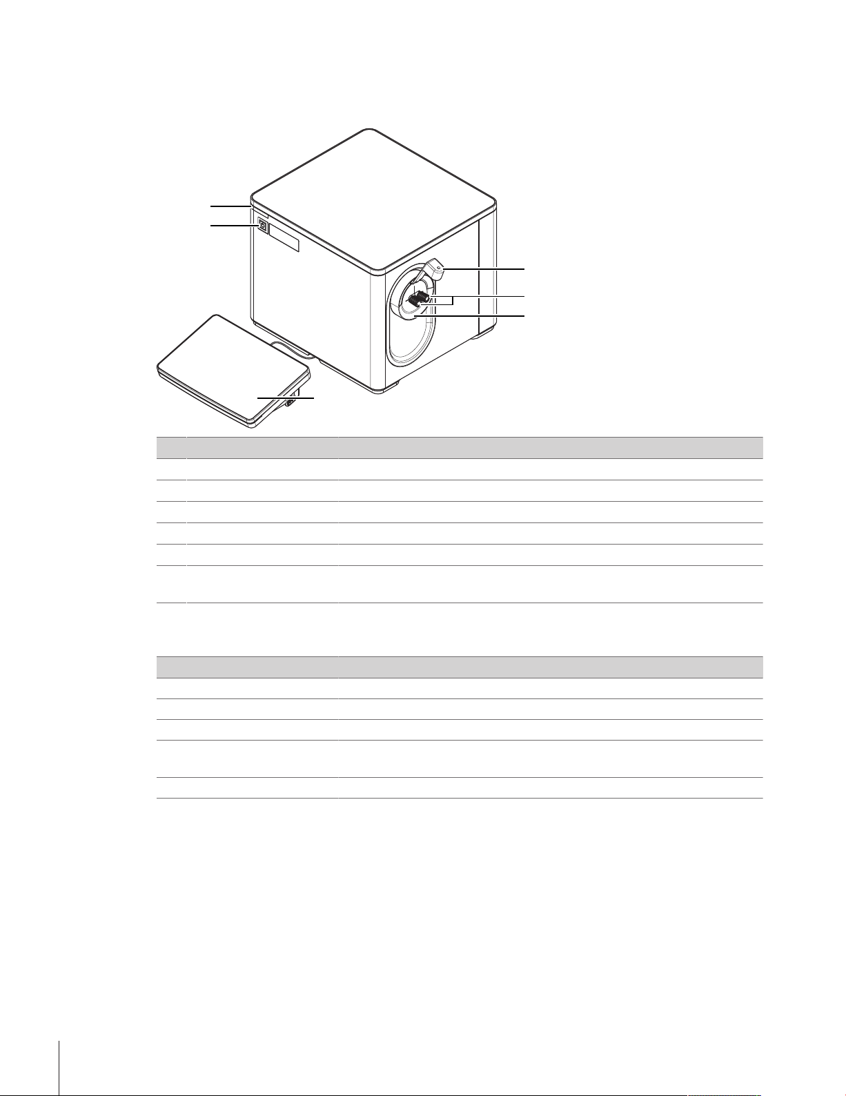
3.1 Overview density meter
No. Name Function
Syringe holder
1
Cell adapters Used to fill, drain and dry the measuring cell
2
Protective sleeve Prevents liquid from entering through the opening around the cell adapters
3
Terminal Displays information and is used to enter information
4
Power button Starts up and shuts down the density meter
5
Instrument status light
6
(StatusLight™)
1)
Only included in the scope of delivery of D6
1)
Prevents disturbance of the measuring-cell when the user injects a sample
Provides information about the status of the density meter
Status light
StatusLight Density meter status
Steady, green light The density meter is ready for operation.
Blinking, green light The density meter is performing a task.
Steady, orange light The density meter waits for the user to perform an action.
Blinking, orange light A task has been interrupted, for example because a value lies outside of its
limits.
Steady, red light An error has occurred during task execution.
Design and function8 Density Meter Excellence
Page 11

3.2 Rear panel
1
15 13 34678910111214 5
2
No. Name Function
1 DryPro / pH/Cond
Fan and ventilation
2
openings
3 Air In
4 CAN out
5 Power Supply
6 USB 1 / USB 2
7 PC
8 SPR200
9 Terminal
10 DryPro
11 Ethernet
12 Aux
13 Automation
14 LevelSens
15 ErgoSens
Mounting plate to attach a DryPro, or an external flow cell to measure pH or
conductivity
Move air over the heat sink of the Peltier element
Gas inlet to connect a source of dry air and prevent condensation outside of
measuring cell
RJ12 socket to connect a LevelSens box
DC Socket to connect the AC adapter
USB-A socket to connect USB devices, for example printers, barcode readers
or an InMotion™ Autosampler
USB-B socket to connect a computer
6-pin Mini-DIN socket to connect the filling pump SPR200
19-pin Mettler-HDMI socket with non-standard pin assignment, reserved to
connect the terminal and no other display device
5-pin Mini-DIN socket to connect the drying pump DryPro
RJ45 socket to connect a network
5-pin Mini-DIN socket to connect an auxiliary instrument
9-pin male D-sub socket to connect a sample delivery and cleaning unit
5-pin Mini-DIN socket to connect the fluid-level sensor LevelSens
3.5mm jack socket to connect the infrared motion-sensor ErgoSens
See also
2 Accessories}Page102
Design and function 9Density Meter Excellence
Page 12

3.3 Terminal
1
2
3
456
T
s
t
A
B
A
f =
1
T
[s
-1
]
No. Name Function
Touch screen Displays information and can be used to enter information
1
USB-A socket Is used to transfer data to and from a USB flash drive
2
Terminal status light
3
(StatusLight™)
4
Provides information about the status of the density meter
Opens a window with general information about the density meter
5
6
Opens the home screen
Ends all running tasks
3.4 The principle of density measurement
The density measurement is based on the electromagnetically
induced oscillation of a U-form tube made of glass. A magnet is
fixed to the U-tube and a transmitter induces the oscillation. The
period of oscillation T is measured by a sensor.
A complete forward and backward vibration is known as a
period, its duration is the oscillation period T. The maximum
deflection in the vertical direction is the amplitude A.
Measuring tube with defined volumetric capacity:
A) Excitation: Magnetic
B) Detection: optical
The number of periods per second is the frequency f. Each glass tube oscillates with its own intrinsic frequency:
Design and function10 Density Meter Excellence
Page 13

The frequency is a function of the total mass and changes when the tube is filled with a gas or liquid. If the
T =
[s
]
2π
ρ
V
c
+
m
c
K
ρ
ρ
=
K
4π
2
V
c
T
2
-
m
c
V
c
ρ = AT + B
2
F =
4
π
2
V
K
c
T
2
=
ρ Aρ
W
-
T
2
A
T
2
W
-
ρ
ρ
F (
OSC
2
A
OSC
2
S
-
)
=
ρ Aρ
S
-()
ρ
S
=
ρ
A
-
F (
OSC
2
A
OSC
2
S
-
)
mass is increased, the frequency falls, i.e. the period of oscillation T becomes longer, according to the below
formula:
: Density of the sample in the measuring cell [g/cm3]
VC: Volume of the sample (capacity of the measuring cell) [cm3]
mc: Mass of the measuring cell [g]
K: Measuring cell constants [g/s2]
The density ρ can hence be calculated as follows:
The relationship between the density and the period of oscillation T is as follows:
A and B are constants that depend on the elasticity, structure and mass of the measuring cell. As they vary from
cell to cell, they must be determined by means of direct measurement. This is known as a coefficient determination or adjustment of the instrument. The coefficient F of the measuring cell is calculated by measuring the
period of oscillation T of two standard substances (usually air and water) with known densities:
= Density of air [g/cm3]
A
= Density of water [g/cm3]
W
TA = Period of oscillation of the air measurement [s]
TW = Period of oscillation of the water measurement [s]
After the coefficient F of the measuring cell has been determined by an adjustment, the unknown density of a
substance S can be calculated via the following formulas, whereby TA, TS and TW in the following formulas no
longer represent the period of oscillation itself but the oscillation value OSC derived from it:
The following diagram shows the how the density of an unknown substance is determined:
Design and function 11Density Meter Excellence
Page 14

OSC
2
A
OSC
2
OSC
2
S
OSC
2
W
Note
The coefficient F is temperature-dependent. The volume of the measuring cell and hence its period of oscillation
changes with the temperature. For very precise measurements, the coefficient of the cell should be determined
for the temperature at which you measure your samples.
The oscillation value OSC described here is required to calculate the coefficient of the measuring cell and hence
the density of the unknown sample. The period of oscillation T itself is not displayed on the instrument. The
density meters only display the so-called oscillation value OSC that is directly derived from the period of oscillation T.
The oscillation value OSC is thus only an auxiliary value that represents the period of oscillation in high
resolution as a whole number without digital places.
3.5 Design of the measuring cell and the temperature controller
For a specific determination of the density a very precise measurement and adjustment of the temperature must
be ensured.
As the temperature of the probe cannot be measured directly in the U-form tube without falsifying the
measurement of the oscillation, the temperature is measured via three thermistors at different locations. The
temperature is measured at four different points:
Temperature 1: Sensor in the measuring cell, directly above the surface of the U-tube. This temperature
is shown as a status display (cell temperature).
Temperature 2: Temperature of the thermoblock (block temperature) (not displayed)
Temperature 3: Reference temperature (not displayed)
Temperature 4 Ambient temperature (not displayed)
The following schematic diagram shows the design of the module:
Design and function12 Density Meter Excellence
Page 15

1
2
3
4
5
6
7
8
9
10
1: Temperature controller
t
3
2
4
1
2: Peltier element
3: Magnetic excitation/ oscillation measurer
4: Heat insulation
5: Magnet
6: Temperature sensor 2 (block
temperature)
7: Temperature sensors 1 (cell
temperature) and 3 (reference
temperature)
8: U-tube
9: Thermoblock
10: Temperature sensor 4
(ambient temperature)
During a measurement the temperature of the sample must be regulated (heating or cooling) to precisely
correspond to the selected measuring temperature. The density of the sample changes during heating or
cooling (density is temperature-dependent!). The same is true for the resonance frequency of the U-tube. The
sample temperature corresponds exactly to the selected temperature (and hence the cell temperature, Sensor 1)
when the resonance frequency stabilizes. However it takes a long time before this thermal equilibrium is
completely established. With respect to the shorter measuring times, various measurement reliabilities can be
chosen so that even before the measurement is completed the temperature and the OSC can be extrapolated to
stable end values. This means that sufficiently accurate results can be obtained before stabilization:
End of the measurement with:
1) Meas. reliability "Maximum":
T and OSC stable
2) Meas. reliability "High": T
and OSC extrapolated; narrow
tolerance
3) Meas. reliability "Medium": T
and OSC extrapolated; medium
tolerance
4) Meas. reliability "Minimum":
T and OSC extrapolated; greater
tolerance
Design and function 13Density Meter Excellence
Page 16

4 Installation and commissioning
4.1 Scope of delivery
Part Order number D4 D5 D6
Density meter – • • •
Extern. Power Supply 120W 30298362 • • •
Power cable (country-specific) – • • •
Terminal WVGA 7inch AnaChem
• Terminal
• HDMI cable
Syringe adapter (1 pc) 51337154 • • •
Waste tube
600mm, M8 connector
Disposable syringe (3 pcs)
10mL
Syringe Holder Dx
• Protective sleeve for syringe holder
• Syringe holder and 2 screws
• Syringe adapter
• Tube with 2 M8connectors,
length 280mm
• Torx screwdriver 10
Combined water standard
9mL, density/refractive index
– • • •
51337223 • • •
– • • •
30474897 – – •
51338010 • • •
User Manual – • • •
Declaration of conformity – • • •
Installation and commissioning14 Density Meter Excellence
Page 17

Part Order number D4 D5 D6
Test report – • • •
4.2 Download the Reference Manual
1 Go to the website www.mt.com/library.
2 Select the Technical Documentation tab.
3 Enter the product type in the search field and start the search.
4 Select the Reference Manual from the result list.
5 Select the link.
ð The Reference Manual is either opened or downloaded depending on the browser settings.
6 Check which firmware version is installed on your density meter.
7 If the Reference Manual is not written for the installed firmware version, contact your authorized METTLER
TOLEDO service representative or dealer.
u www.mt.com/contact
See also
2 Introduction}Page5
2 View the firmware version}Page96
4.3 Unpack the density meter
1 Remove the density meter from the protective packaging.
2 Store the packing material for later transport over long distances.
3 Check if you received all parts listed in the scope of delivery.
4 Inspect the parts visually for flaws or damage.
5 If parts are missing or damaged, report it to your authorized METTLER TOLEDO service representative or
dealer.
u www.mt.com/contact
See also
2 Scope of delivery}Page14
4.4 Position the density meter
The density meter has been developed for indoor operation in a room with stable temperature.
The following site requirements apply:
• Dew point below measurement temperature
• Ventilation as needed by the chemicals that are used
• Ambient conditions within the limits specified in the technical data
• No powerful vibrations
• No direct sunlight
• No corrosive gas atmosphere
• No explosive atmosphere
• No powerful electric or magnetic fields
Procedure
1 Place the density meter on a level surface.
2 Make sure that there are at least 15 cm clearance behind the density meter.
Installation and commissioning 15Density Meter Excellence
Page 18

3 Make sure that nothing blocks the ventilation openings in the rear panel of the density meter.
1
See also
2 Technical data}Page99
4.5 Connect the density meter to the power supply
The AC adapter is suitable for all supply line voltages ranging from 100...240 V AC and 50/60 Hz.
WARNING
Danger of death or serious injury due to electric shock!
Contact with parts that carry a live current can lead to death or injury.
1 Only use the METTLER TOLEDO power supply cable and AC adapter designed for your
instrument.
2 Connect the power cable to a grounded power outlet.
3 Keep all electrical cables and connections away from liquids and moisture.
4 Check the cables and the power plug for damage and replace damaged cables and
power plugs.
NOTICE
Danger of damage to the AC adapter due to overheating!
If the AC adapter is covered or in a container, it is not sufficiently cooled and overheats.
1 Do not cover the AC adapter.
2 Do not put the AC adapter in a container.
1 Install the cables in such a way that they cannot be damaged or interfere with operation.
2 Insert the plug of the power cable in the socket of the AC adapter.
3 Insert the plug of the AC adapter in the Power
Supply(1) socket on the rear panel.
4 Insert the plug of the power cable into a grounded
power outlet that is easily accessible.
4.6 Disconnect the density meter from the power supply
The density meter is shut down.
§
1 Pull the plug of the power cable out of the power outlet.
2 Pull the plug of the AC adapter out of the Power Supply socket on the rear panel.
Installation and commissioning16 Density Meter Excellence
Page 19

4.7 Connect, adjust and disconnect the terminal
1 2
1
1
4.7.1 Connect the terminal
The density meter is shut down.
§
1 Insert one of the plugs of the supplied terminal cable in the socket(1) on the back of the terminal.
2 Insert the other plug of the terminal cable into the Terminal socket(2) on the rear panel.
3 Start up the density meter.
ð The density meter automatically detects the terminal and activates it.
See also
2 Start up the density meter}Page72
4.7.2 Adjust the angle of the terminal
The angle of the terminal has twopositions.
Procedure
No task is running.
§
− To increase the angle of the terminal, fold out the two
feet(1) at the underside of the terminal.
4.7.3 Disconnect the terminal
The density meter is shut down.
§
1 Pull the plug of the terminal cable out of the socket on the back of the terminal.
2 Pull the plug of the terminal cable out of the Terminal socket on the rear panel.
See also
2 Shut down the density meter}Page72
Installation and commissioning 17Density Meter Excellence
Page 20

4.8 Install the syringe adapter
1
2
1
2
1
2
1 Screw the syringe adapter(2) into the front cell
adapter(1).
2 Make sure that the connection is tight.
4.9 Install the waste tube
1 Screw the connector of the waste tube(2) into the rear
cell adapter(1).
2 Make sure that the connection is tight.
3 Place the end of the waste tube(1) into the waste
container(2).
4 Shorten the waste tube so that the end of the waste
tube(1) is above the level of the waste.
4.10 Install accessories
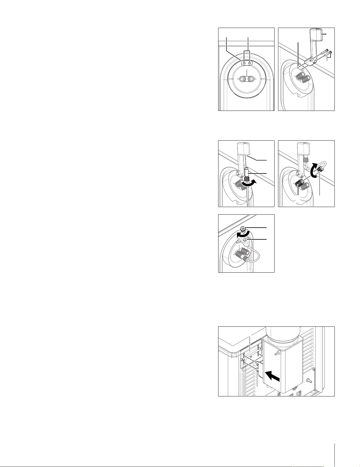
4.10.1 Install and connect the syringe holder
4.10.1.1 Install the syringe holder
1 Remove the protective sleeve. See [Remove the protective sleeve}Page95].
Installation and commissioning18 Density Meter Excellence
Page 21
1 2
3
4
5
2 Install the protective sleeve supplied with the Syringe
1
2
3 4
1
2
1
2
Holder Dx.See [Install the protective
sleeve}Page96].
3 Make sure that the opening for the syringe holder(1) is
over the two mounting holes for the syringe holder(2).
4 Insert the syringe holder(4) in the opening for the
syringe holder(3).
5 Insert the two screws(5) in the two openings in the
syringe holder and the mounting holes.
6 Screw in the screws and tighten them.
4.10.1.2 Connect the syringe holder
The syringe holder is installed.
§
1 Screw one of the M8 connectors(2) of the syringe-
holder tube from below about halfway into the
opening(1).
2 Screw the other M8 connector(4) of the syringe holder
tube into the front cell adapter(3) and tighten it.
3 Screw the syringe adapter(1) from above into the
opening(2) and tighten it.
4.10.2 Set up the drying pump
4.10.2.1 Install the DryPro
The DryPro is assembled as described in its User Manual.
§
The density meter is shut down.
§
1 Align the hooks(2) of the DryPro with the openings of
the mounting plate(1).
2 Insert the hooks into the openings.
Installation and commissioning 19Density Meter Excellence
Page 22

3 Move the DryPro downward until it clicks in place.
21
Home
Tasks
Log out User data Barcode start Start
Methods /
Products
Series
Results
Setup
Manual
08/15/2018Administrator
20.00
1
D5
0.00122
d [g/cm3]
4.10.2.2 Connect the DryPro
The DryPro is installed.
§
The density meter is running.
§
The home screen is open.
§
1 Insert the plug(2) of the DryPro in the DryPro
socket(1) on the rear panel.
ð The density meter detects and configures the
DryPro.
2 Go to Setup(1) > Hardware > Automation.
3 Check that the DryPro has the Status Installed.
See also
2 Start up the density meter}Page72
4.11 Setup
This section tells you how to set up the density meter in accordance with your requirements so that you can
carry out the measurements.
The following summary shows the buttons available in Setup for the various setting options:
Adjustments & Tests
Hardware
Adjustment sets
Test sets
Cell
Automation
External instruments
Peripherals
Sensors
Auxiliary instruments
Installation and commissioning20 Density Meter Excellence
Page 23

User settings
Language
Screen
Beep
Shortcuts
Keyboards
Global settings
Tables & Values
Maintenance & Service
System
User management
Analysis and resources behavior
Physical Properties
Tables
Auxiliary values
MT service
Import / Export
Add external cell
Reset to factory settings
Firmware
Update
Hardware / Firmware summary
Cell
Touch screen adjustment
Export of adjustments / Tests / Measurements
The "Expired Resources" button
The Expired Resources button is located on the setup overview screen. It provides you with a summary of all
expired resources, stating the: type, name and expiration date of the respective resource.
Expired resources are entered if the setting "Monitoring adjustment set/test set/auxiliary value" is activated
during setup.
Below you will find a detailed description of the setting options available in setup:
4.11.1 Adjustments & Tests
Navigation: Home > Setup > Adjustments & Tests
Adjustment and test sets can be administered as described below. You can create new sets and delete existing
ones (when deleting you receive a prompt with the option to cancel). Before an adjustment or test can be
performed, an adjustment or test set must be defined.
A maximum of six different adjustment sets or test sets respectively can be entered in the set list.
Before an adjustment or test can be performed, an adjustment or test set must be defined.
4.11.1.1 Adjustment Sets
Via the button Adjustment sets you will obtain a list of the defined sets. The default set "Air&Water20.00C" is
always available and cannot be deleted. When you click the sets, you obtain more detailed information about
the individual sets. The parameters "Adjustment mode", "Temperature" and "Set name" are displayed.
Creating adjustment sets
You can create your own adjustment sets via the button New. The Adjustment set parameters dialog opens.
Installation and commissioning 21Density Meter Excellence
Page 24

Parameter Description Values
Adjustment mode Defines the standard that is used for the adjustment procedure.
Temperature Defines the temperature at which the procedure is performed. 0.00…100.00°C |
Set name Specify a descriptive name of your choice. 1…30 characters
Delete adjustment sets
1 To delete a created set, click the desired entry in the Adjustment sets dialog.
2 In the Adjustment set parameters dialog, click the button Delete.
ð When a set is deleted, the set history will also be deleted. Methods that refer to the deleted set are no
longer executable.
4.11.1.2 Test Sets
Via the button Test sets you receive a list of the defined sets. The default set "Water20.00C" is always available
and cannot be deleted. When you click the test sets, you obtain more detailed information about the individual
sets. The parameters "Test mode", "Temperature", "Set name" and depending on the mode "Standard name" are
displayed.
Creating test sets
You can create your own test sets via the button New. The Test set parameters dialog is opened.
Standards requires a valid adjustment with Air&Water at this
temperature. (Air&Standard and Water&Standard are not
available for refractometers).
Air&Water |
Air&Standard |
Water&Standard |
Standards
32.00…212.00°F
Parameter Description Values
Test mode Defines the standard that is used for the test procedure. Air | Standard | Brix
Temperature Defines at which temperature the test will be performed. -
Standard name Specify a descriptive name of your choice. 1…30 characters
Set name Specify a descriptive name of your choice. 1…30 characters
Delete test sets
1 To delete a created set, click the desired entry in the Test sets dialog.
2 In the Test set parameters dialog click the button Delete.
ð When a set is deleted, the set history will also be deleted. Methods that relate to the deleted set are no
longer executable.
4.11.2 Hardware
Navigation: Setup>Hardware
In this dialog window you can configure all the hardware components connected to the meter. These include:
• Cell
• Automation
• External instruments
• Peripherals
• Sensors
• Auxiliary instruments
standard
4.11.2.1 Cell
Navigation: Home > Setup > Hardware > Cell
Installation and commissioning22 Density Meter Excellence
Page 25

The measuring cell is connected via an internal interface in the compact device. The instrument can be
extended to create a 2–cell instrument (see also "Setup: Maintenance & Service > [Add external
cell}Page40]").
− Touch the button Cell in the Hardware dialog.
ð With single cell instruments you go directly to the list with the cell parameters
ð In the case of two cell instruments the connected cells are listed. You have to touch one of the displayed
cells so that the Cell parameters dialog opens.
ð The Cell parameters dialog is opened.
Parameter Description Values
Cell Name of the measuring cell -
Type Measuring cell type -
Status Shows whether the cell is connected. -
Serial number Serial number of the cell -
If an adjustment has been performed, an entry in the adjustment set appears in the setup of the corresponding
cell. If you touch the entry, the data of the most recent adjustment that was executed with the set will be
displayed.
Parameter Description Values
Adjustment set By touching the set entry, you obtain the values for the most
-
recent adjustment of this set.
Monitoring
adjustment set
Monitoring of the service life of the adjustment can be activated.
The process, if the service life of a set has expired, is defined in
-
the method function "Measure".
Adjustment
interval
Reminder Before the set expires, a message appears indicating that the
Days before
Validity of adjustment "Monitoring adjustment
set" activated
"Monitoring adjustment
adjustment or test has expired.
set / test set" activated
Specifies the number of days after which a warning is triggered. "Reminder" activated
expiration
If a test has been performed, an entry in the test set appears in the setup of the corresponding cell. If you touch
the entry, the data of the most recent adjustment that were executed with the set will be displayed.
Parameter Description Values
Test set By touching the set you go to the values for the most recent test
-
for this set.
Monitoring test
set
Monitoring of the service life of the test can be activated. The
process, if the service life of a set has expired, is defined in the
-
method function "Measure".
Test interval Service life of test "Monitoring test set"
activated
Parameter Description Values
Reminder Before the set expires, a message appears indicating that the
adjustment or test has expired.
Days before
Specifies the number of days after which a warning is triggered. "Reminder" activated
"Monitoring adjustment
set / test set" activated
expiration
Via the button History you go to a list that contains a maximum of ten adjustment or test entries for the selected
set.
For the adjustment, the oscillation values OSC1 and OSC2 (for both adjustment standards) are displayed, while
for the cell test the deviation of the measured density (d
) from the nominal value
meas
) is shown.
set
Installation and commissioning 23Density Meter Excellence
Page 26

The history can be displayed in graphic form via the button Graph. You can view the history data by touching
an entry.
See also
2 Add External Cell}Page40
4.11.2.2 Automation
Navigation: Home > Setup > Hardware > Automation
The automation units that can be installed are listed below:
• DryPro (drying pump)
• SPR200 (sample pump)
• SC1 (automation unit for a sample)
• SC30 (automation unit for 30 samples)
• InMotion (automation unit for up to 303 samples)
The peripheral devices have an automatic PnP (Plug and Play) – identification. They can also be manually
created in the setup.
Via the button Automation in the Hardware dialog, you access a list with defined automation units. By
touching a list entry, you obtain more detailed information about the corresponding automation unit.
Parameter Description Values
Type Instrument Type -
Power purge unit The external diaphragm (Optional) has a much higher output
Heating option This is where the heating option is activated. The temperature is
Limit sensor Optical sensor that detects the sample and prevents it leaving the
External drain
valve
Solvent 1 Specifies the solvent at the connection Rinse 1 "Type" = "SC1"/ "SC30"
Solvent 2 Specifies the solvent at the connection Rinse 2 "Type" = "SC1"/ "SC30"
Speed "Low" Value for speed level "Low" of the SPR200 or InMotion
Speed "Medium" Value for speed level "Medium" of the SPR200 or InMotion
Speed "High" Value for speed level "High" of the SPR200 or InMotion
than the diaphragm pump integrated in the SC1/SC30. The pump
is actually adjusted at the SC1/SC30.
directly set on the heating unit.
heated area of the heating option (info field).
Located in the heating unit. Prevents the samples flowing back
after filling process (info field).
autosampler (in % of the maximum speed).
autosampler (in % of the maximum speed).
autosampler (in % of the maximum speed).
"Type" = "SC1"/ "SC30"
"Type" = "SC1"/ "SC30"
"Type" = "SC1"/ "SC30"
"Type" = "SC1"/"SC30"
"Type" = "SPR200" /
"InMotion"
"Type" = "SPR200" /
"InMotion"
"Type" = "SPR200" /
"InMotion"
Rate at 100% Value for max. possible pump output (depending on the installed
"Type" = "InMotion"
pump which is defined as sampling pump).
Stirrer output Specifies the pump/stirrer port on the InMotion where your stirrer
"Type" = "InMotion"
is connected.
Sampling pump
output
PowerShower
output
Specifies the pump/stirrer port on the InMotion where your
sampling pump is connected.
Specifies the pump/stirrer port on the InMotion where your pump
for PowerShower is connected.
"Type" = "InMotion"
"Type" = "InMotion"
Rate Value for required pump output for PowerShower. "Type" = "InMotion"
Beaker height Specifies the height of the used beakers. "Type" = "InMotion"
Installation and commissioning24 Density Meter Excellence
Page 27

A distinction should be made between the following two cases in the installation of instruments:
1. There is still no setup entry available in the unit (delivery state).
A new entry has been generated and the parameters automatically generated.
2. A setup entry was previously manually created in the instrument:
The PnP parameters are automatically entered, the remaining parameters, previously edited by the user,
remain unchanged.
When a PnP instrument is unplugged, the status changes to "not installed".
Below is described how you can administer the various devices in setup. This includes the creation of devices
or changing the parameters in the setup.
Create automation units
So that methods for the application of automation units can be created and configured without the automation
unit being connected, these units must be created in the setup via the button New.
Delete automation unit
It is not possible to delete the entry of a connected device.
Note
If you want to delete an entry for a unit that is not connected from the list, a message with the termination
option appears indicating that after deletion the methods that use the external instruments will no longer be
executable.
4.11.2.3 External Instruments
Navigation: Home > Setup > Hardware > External instruments
The external instruments that can be installed are listed below. They all have automatic PnP – identification:
• METTLER TOLEDO S20 – SevenEasy™ pH
• METTLER TOLEDO S30 – SevenEasy™ Conductivity
• METTLER TOLEDO S220 - SevenCompact™ pH/Ion
• METTLER TOLEDO S220 - SevenCompact™ Conductivity
• Lovibond colorimeters PFX880/ PFXi880, PFX950/ PFXi950 and PFX995/ PFXi995 series, Tintometer
• Minolta colorimeters CM-5/ CR-5
Note
• The Lovibond colorimeters can be connected to the USB interfaces. For this purpose the USB – RS232
adapter is required (contained in the connection kit).
• For each device type only one entry is possible.
Install devices
A distinction should be made between the following two cases in the installation of instruments:
1. There is still no setup entry available in the unit (delivery state).
A new entry has been generated and the parameters automatically generated.
2. A setup entry was previously manually created in the instrument:
The PnP parameters are automatically entered, the remaining parameters, previously edited by the user,
remain unchanged.
When a PnP instrument is unplugged, the status changes to "not installed".
• Via the button External instruments in the Hardware dialog, you can obtain the list of instruments. By
touching a list entry, you obtain more detailed information about the corresponding instrument.
Create device
So that methods can be created and configured with external instruments, without having to connect the
instrument, the setup entries of the external instruments can be manually created via the button New.
Note
• The pH and conductivity meters can be assigned names individually using the "Instrument" parameter.
Installation and commissioning 25Density Meter Excellence
Page 28

Delete devices
It is not possible to delete the entry of a connected device.
Note
If you want to delete an entry for a unit that is not connected from the list, a message with the termination
option appears indicating that after deletion the methods that use the external instruments will no longer be
executable.
SevenEasy™ / SevenCompact™ pH/ion and conductivity meters
1 Select the following for the SevenEasy™ and SevenCompact™ measuring instruments (also refer to the
operating instructions for the measuring instrument concerned):
Manual end point measured value acquisition,
set the unit [pH]" ([mV] not supported).
2 For the SevenCompact pH and conductivity meters, the following must also be selected (also refer to the
relevant operating instructions):
an interval time of 1s (in menu>Interval measurements),
interface=printer (in menu>Data transmission),
"Send data to interface" (in "Type of data transmission").
3 For temperature compensation, set the unit [°C] at the measuring instruments. Two types of temperature
compensation exist:
- ATC (automatic temperature compensation) with a temperature sensor connected.
- MTC (manual temperature compensation) with no temperature sensor connected.
Note:
The pH or conductivity meters switch automatically, depending on the arrangement.
If the temperature unit at the pH meter or conductivity meter is set to [°C], the results "TpH" and "TCond" will
be converted to the temperature unit set in the instrument, i.e. either [°C] or [°F] . By contrast, if [°F] is set
at the pH or conductivity meter, no result will be calculated. "--" will be output in the results field.
Note
The conductivity units are [mS/cm]/ [μS/cm] (depending on the range) or [mS/m][μS/m] (depending on the
range). However, the results are expressed in [μS/cm]. If you wish to have the result displayed in [mS/cm] or
[mS/m][μS/m], it will be necessary to recalculate the result using the "Calculation" method function.
Colorimeter
- Lovibond
The Lovibond colorimeter can be used for extinction or transmission measurements. The wavelengths are
output in 5nm (in the range 420 – 710nm).
Note
A color measurement may take longer than 25s.
- Minolta colorimeters CM-5 / CR-5
The Minolta colorimeters can be used for transmission measurements (liquids).
Transmission data are supplied in 10nm increments within the spectral range 360 – 740nm.
A color measurement takes approximately 1s.
The measurements involve high-energy light flashes. For this reason, color scales are not offered for reflection
measurements in the crude oil industry.
Note
• The CR-5 colorimeter does not supply any spectral data.
• Calibration is possible directly at the colorimeter only. The USB link must be disconnected.
• "Illuminant" and "Observer" can be set in the "Configuration" method function. For more information, see
"[Methods and products: Method functions> Configuration}Page50]".
- Color scales
Navigation: Home > Setup > Hardware > External instruments > Parameters
Installation and commissioning26 Density Meter Excellence
Page 29

− Click on "Colorimeter".
ð The "External instrument parameters" dialog appears.
If a device has been connected, a list of color scales is displayed via the Color scales button, that were
available in the most recently connected device. If the device has been manually configured and no device has
yet been connected, then the list is empty.
4.11.2.4 Peripherals
Navigation: Home > Setup > Hardware > Peripherals
In the dialog Peripherals, the following devices and settings can be configured:
• Barcode reader
• USB stick
• Fingerprint reader
• Printer
• Personal Computer (PC) – settings
• Network settings
• Network storage
Below is described how you can administer the various devices in setup. This includes the creation of devices
or changing the parameters in the setup.
Barcode reader
Barcode readers have Plug&Play (PnP) recognition and can be installed via the USB interface.
The following barcode readers can be installed:
• Handheld readers
• Built-in readers
You can create the barcode readers via New. A maximum of one entry can be created for both types.
Parameter Description Values
Type Instrument Type -
Serial number Serial number of the corresponding device -
Barcode Information
Sample ID: on the barcode there is only the sample ID.
Method ID: on the barcode there is the method ID (with this a
-
saved method can be selected during scanning).
Product ID: on the barcode there is the product ID (with this a
saved product can be selected during scanning).
Sample ID/Method ID: on the barcode there are the sample ID and
method ID (with this a saved method can be selected during
scanning).
Sample ID/Product ID: on the barcode there are the sample ID
and product ID (with this a saved product can be selected during
scanning).
Start pos. sampleIDStart position of the sample ID on the barcode "Barcode information"
with sample ID
Number of
characters
Length of the sample ID on the barcode "Barcode information"
with sample ID
Start pos. methodIDStart position of the method ID on the barcode "Barcode information"
with method ID
Number of
characters
Length of the method ID on the barcode "Barcode information"
with method ID
Start pos. productIDStart position of the product ID on the barcode "Barcode information"
with product ID
Installation and commissioning 27Density Meter Excellence
Page 30

Number of
characters
Immediate start If this parameter has been activated, when a task is started with
Length of the product ID on the barcode "Barcode information"
with product ID
"Type" = "Handheld
the barcode reader, the Start analysis dialog is skipped and the
task is started immediately.
reader",
"Barcode information"
with method ID, product
ID or sample ID
Example of barcode with sample ID and method ID (161218522). (Sample ID=1612 and method ID 18522).
• Start pos. sample ID 1
• Number of characters 4
• Start pos. method ID 5
• Number of characters 5
USB stick
Commercially available USB sticks from USB Version 1.1 are supported.
Fingerprint reader
You can use a fingerprint reader to authenticate users on the titrator. In order to do this, the fingerprint reader
must be activated on the titrator. The following parameters are available for this:
Parameter Description Values
Activate
Activates the connected fingerprint reader. -
fingerprint reader
Printer (and USB-RS232 data export)
• Date can be printed with the USB-P25 (strip printer) or with a network printer.
• Data can be exported using the USB data export box. The data are exported in the XML (UTF-8) formats.
Note
• For data export to an RS interface, you need the USB RS232 adapter (USB data export box).
• As desired, data can be printed either as a summary or in a user defined format (via "Print Mode" parameter
"Report" method function; also see "Methods and products: Methods> Method functions> Report")
Note
For printing/USB data export, the following should be taken into consideration:
• In the "Report" method function, the "Print / USB-RS232 data export" parameter must be selected.
You can define the following parameters via the Printer button (Home>Setup>Hardware>Peripherals):
Parameter Description Values
Printer type
USB compact printer
The USB compact printer does not support all languages. This
printer can only print out a limited quantity of analysis data and
results.
USB-RS232 data export
For the RS-232 data export, the data is transmitted regardless of
the selected language. Only a limited quantity of data and results
can be exported.
Network printer
Every connected printer in your local network that supports HP
PLC 3 or Epson ESC/P 2 can be used.
Status Indicates whether the selected printer type is installed (info field). Only for printer type
"USB compact printer"
and "USB-RS232 data
export"
Installation and commissioning28 Density Meter Excellence
Page 31

Baud rate The baud rate for data transmission via the USB-RS232 interface. "Printer type"= "USB-
RS232 data export"
Data bit The number of data bits is displayed (info field). "Printer type"= "USB-
RS232 data export"
Stop bit The number of stop bits is displayed (info field). "Printer type"= "USB-
RS232 data export"
Parity Defines the parity protocol. ("Even", "Odd", "None") . "Printer type"= "USB-
RS232 data export"
Handshake Data transmission via the RS-232 interface ("Xon-Xoff", "None"). "Printer type"= "USB-
RS232 data export"
Type Choose the printer protocol. "Printer type"= "Network
printer"
Network name Define your local network name here. "Printer type"= "Network
printer"
Port number Define your local port number here. "Printer type"= "Network
printer"
Paper size Choose the print-format of the report (A4 / Letter). "Printer type"= "Network
printer"
PC settings
Only one PC connected per measuring instrument can be present at one time. You can select if you wish to set
up a connection to the laboratory program "LabX".
Parameter Description Values
Set up connection
to LabX at start
up
If this parameter is activated, a connection to LabX will be established on startup.
-
Note
Changes to the PC settings are not implemented until after the measuring instrument is rebooted.
Network settings
You can define the following parameters for the network – settings:
Parameter Description Values
Type Type of network connection -
Obtain IP address
automatically
IP Address IP address of the instrument -
Subnet mask Subnet mask of the device -
Standard gateway Standard gateway of the device "Type" = "Ethernet"
If this device has been activated, the device automatically obtains
an IP address.
"Type" = "Ethernet"
Note
The device automatically reboots after any change to the network settings.
Network storage
You can define the following parameters for a network – storage:
Parameter Description Values
Transfer via
Server PC or server name. Users should have read-write access.
Share name Name of the share which is defined for the shared folder. -
Method for transferring data (only Network share).
Maximum 60 alphanumeric characters.
-
-
Installation and commissioning 29Density Meter Excellence
Page 32

User name Type in the user name for accessing the shared folder. The user
name must be defined in the setup for the shared folder.
Domain Domain name of the server where the shared folder is located. -
Password Password for the network share. -
Target folder
Defines the name of the Target folder where the data is saved.
The Target folder is a subfolder in the shared folder.
-
-
First folder level If specified, the First folder level is a sub-folder in the Target
Second folder
level
4.11.2.5 Sensors
Navigation: Home > Setup > Hardware > Sensors
Sensors can be activated in the setup. The following sensors can be connected:
ErgoSens: Infrared sensor for contactless start of measurement (see "Analysis sequence: Start of analyses").
Before you can use ErgoSens, it has to be activated:
Parameter Description Values
Activate ErgoSens Activates the ErgoSens -
WasteSens or LevelSens: Level sensors for waste bottle.
It is determined whether the maximum filling level of the waste bottle is reached. If the maximum filling level
has been reached, a message appears prompting the operator to empty the waste bottle. The task is then interrupted.
Before you can use WasteSens or LevelSens, it has to be activated:
folder. This folder can optionally be used to sort data. (None |
User name | Titrator ID | Date | Method ID)
Default: None
If specified, the Second folder level is a second sub-folder in the
Target folder. This folder can optionally be used to sort data.
(None | User name | Titrator ID | Date | Method ID)
Default: None
Only if First folder level = activated
-
-
Parameter Description Values
Activate
WasteSens/
LevelSens
AtmoSens: Atmospheric pressure sensor for measuring the absolute air pressure.
If an AtmoSens is connected, the atmospheric pressure (if required) is measured with the AtmoSens. If no
AtmoSens is connected, the air pressure is read out from the current value from Home > Setup> Global
settings> Physical properties.
Parameter Description Values
Verify AtmoSens
availability
activates the WasteSens or LevelSens -
If this parameter is activated, the use of the AtmoSens is enforced
for tasks which require the pressure.
4.11.2.6 Auxiliary instruments
Navigation: Setup>Hardware>Auxiliary Instruments
Auxiliary instruments can be any instruments that access the 24V output or USB-RS232 adapter of the
measuring instrument and that are to be used in a method.
An auxiliary instrument that accesses the 24V output is switched on for a predefined period and then switched
off again via the corresponding command. The instruments are controlled via the "Auxiliary instrument" method
function.
-
Installation and commissioning30 Density Meter Excellence
Page 33

Auxiliary instruments form part of a method, while peripheral devices are classified as input/output devices
(printers, barcode readers etc.), which do not have direct access to methods.
Starting from the auxiliary instrument list, you can add new auxiliary instruments or select existing ones or
modify their parameters. In addition, the selected auxiliary instruments can be deleted.
Note
A maximum of 30 auxiliary instruments can be entered.
Choose the New button in the Auxiliary Instruments dialog window to open the Auxiliary Instrument
§
Parameters dialog.
1 Before a new auxiliary instrument can be added, you must first use the "Control type" parameter to select
the manner in which the auxiliary instrument is to be controlled:. The following values are available for
"Control type":
ð 24V output
ð USB-RS-232
2 You can assign a name of your choice to the auxiliary instrument.
The parameters for the control types are listed below:
24V output
Parameter Description Values
Control type The control type of the auxiliary instrument. USB-RS232 | Output
24V
Name Defines the name of the auxiliary instrument. -
USB-RS-232 interface
Parameter Description Values
Control type The control type of the auxiliary instrument. USB-RS232 | Output
24V
Name Defines the name of the auxiliary instrument. -
Adapter Defines which adapter is used. Maximum 2 auxiliary instruments
of type USB-RS-232 can be used in the same method (by using
adapter 1 and 2)
Parameter Description Values
Baud rate The baud rate for data transmission via the RS-232 interface of
the adapter.
Data bit Defines the number of data bits. "Control type" = "USB-
Stop bit Defines the number of stop bits. (2 stop bits can only be selected
if 7 data bits are also selected at the same time.)
Parity Defines the parity protocol. "Control type" = "USB-
Handshake Data transmission via the RS-232 interface of the adapter. "Control type" = "USB-
"Control type" = "USBRS232"
"Control type" = "USBRS232"
RS232"
"Control type" = "USBRS232"
RS232"
RS232"
Note
A suitable adapter (USB data export box) is required for the USB-RS-232 connection.
4.11.3 Language
Navigation: Home > Setup > User settings > Language
The following languages are available:
• German
Installation and commissioning 31Density Meter Excellence
Page 34

• English
• French
• Italian
• Polish
• Portuguese
• Spanish
• Chinese
• Russian
The language can be defined both for the operation of the terminal as well as for the protocols that are to be
printed out from a printer.
Parameter Description Values
Touchscreen Language of the user interface -
Report
Note
*
Chinese can not be selected as language for reports
4.11.4 Screen
Navigation: Home > Setup > User – settings > Screen
The following parameters can be set in the screen settings:
Language of the printout*
-
Parameter Description Values
Primary color Color of the user interface -
Brightness Brightness of the display -
Button shape Shape of buttons on the touchscreen -
Screen saver Activates screen saver -
Wait time Time for the display of the screen saver Activates screen saver
4.11.5 Beep
Navigation: Home > Setup > User settings> Beep
The audio signal is set specifically for each user. You can activate the audio signal in the Audio-Signal
settings dialog.
4.11.6 Shortcuts
Navigation: Home > Setup > User – settings > Shortcuts
In this dialog, every user has the opportunity to administer his or her own selected shortcuts.
The list of all shortcuts for the logged in user can be viewed. Individual shortcuts can be selected and deleted.
You can determine the following parameters:
Parameter Description Values
Description This text is the name of the shortcut that is displayed in the
Immediate start When the shortcut is pressed, the display switches directly over to
Homescreen
Position
Homescreen.
the online screen without opening the Start analysis dialog.
Selection of the position on the Homescreen -
Installation and commissioning32 Density Meter Excellence
Page 35

4.11.7 Keyboards
Navigation: Home > Setup > User – settings > Keyboards
In the Keyboard settings dialog, you can define the layout for the alphanumeric and the numeric input fields.
The following settings are available:
Parameter Description Values
ABC keyboard Defines the layout of the alphanumeric input field. -
123 keyboard Defines the arrangement of the keys for the numeric input field. -
4.11.8 Global Settings
Navigation: Home > Setup > Global setting
In the Global Settings, you can make general settings to the measuring instrument that apply to all users of the
instrument. The settings in this dialog can only be changed by users with the appropriate authorizations.
Global settings include:
• The system settings
• User management for creating user accounts and assigning rights.
• The settings for Analysis and resources behavior.
• Physical properties for defining the "Temperature unit" and the air pressure.
4.11.8.1 System
Navigation: Home > Setup > Global settings > System
In the System settings dialog the following buttons are available:
• Identification:In this menu you can give the measuring instrument a freely definable ID consisting of at
least four characters.
In addition the following information is displayed: Device, serial number and firmware version.
• Date / time:You can define the format used to display the date and time and set the device date and time.
• Data storage: If this parameter is activated, all results that are saved under Home > Results are deleted
(only when device is shut down).
4.11.8.2 User Management
Navigation: Home > Setup > Global settings > User management
By means of the User management dialog you can administer users and account policies for the instrument.
A maximum of 30 different users can be defined, from which only maximum one may be logged in with the
instrument (1 user operation).
User accounts can be deleted and edited.
There is a default user with the user name "Administrator" (user group: Administrators). This cannot be deleted.
4.11.8.2.1 Users
Navigation: Home > Setup > Global settings > User management > User
Via the button New in the User dialog you can open the User parameters of the dialog. It is possible to define
new users here.
Note
"User management" is the only area in which users with administrator rights are able to edit settings and,
therefore, create or make changes to users.
Create a new user in the User parameters dialog as follows:
1 Define a user name.
Installation and commissioning 33Density Meter Excellence
Page 36

2 Assign the user to a group. The following user groups are available:
Administrator
Expert
Technician
Operator
Note
For information on the rights of these user groups, see "[Setup (Setup: Global settings> User management>
User groups}Page34]".
The following parameters are available in the User parameters dialog:
Parameter Description Values
User name The user is uniquely identified in the system via the name. -
Full Name Complete name of the user. -
User Group Selection of the user group for the user. Depending on the user
group the user has various rights.
Reset password Resets the password for the user to "123456". Activates "Enforce
password/fingerprint"
Lock user Locks the user. Activates "Enforce
password/fingerprint"
Enforce password
change
With the next login the entry of a new password will be enforced. Activates "Enforce
password/fingerprint"
Created by The administrator logged in at time of creation -
Created on Date of creation and time (info field) -
Modified by The administrator logged in at time of creation -
Modified at Change date and time (info field) -
4.11.8.2.2 Account Policy
Navigation: Home > Setup > Global setting > User management > Account policies
The following parameters can be edited in the dialog:
Parameter Description Values
Enforce
password/finger
print
Min. password
length
If the parameter "Enforce password" is deactivated, then the instrument starts directly, i.e. not via the login
screen (only if one user is defined – corresponds to the factory settings). If several users are defined, the user
name can be selected in the login screen from a list.
4.11.8.2.3 User Groups
Each user is assigned to a user group. The following four user groups (with decreasing rights going
downward) should be distinguished:
• Administrator
• Expert
• Technician
• Operator
The following table presents the user rights that are assigned to the corresponding user group:
If this parameter has been activated, you can only log in by
entering the password (or via the fingerprint reader, if the
parameter "Activate fingerprint reader" is activated, in Home >
Setup> Hardware> Peripherals> Fingerprint
reader).
The minimum length of the user passwords Activates "Enforce
password/fingerprint"
Installation and commissioning34 Density Meter Excellence
Page 37

List of user rights
Right Minimum required user group
Start analysis via Shortcuts. Operator
Start analysis via Start button in the Homescreen
Operator
Start analysis with ErgoSens Operator
Start analysis from method editor (for method type:
Technician
measurement, cleaning and test), product and series
editor (for method type: measurement, cleaning, test
and adjustment)
Adding/deleting items for series in the Start analysis
Technician
dialog (does not apply for adjustment-type methods)
Executing manual operations Technician
Editing shortcuts
Technician
(Setup>User settings)
Including and excluding results Technician
Deleting results Expert
Adding/deleting items for series in the Start analysis
Expert
dialog (also applies for adjustment-type methods)
Setting the language for touchscreen and reports Expert
Start analysis from method editor (for method type:
Expert
measurement, cleaning, test and adjustment)
Editing methods, products, series Expert
Editing "Adjustments & Tests"
Expert
(Home > Setup )
Editing "Hardware"
Expert
(Home > Setup)
Editing "Analysis and resources behavior"
Expert
(Home > Setup > Global setting)
Editing "Tables & Values"
Expert
(Home > Setup)
Setting the language for reports Expert
Editing "Physical properties"
Expert
(Home > Setup > Global setting)
Running "Maintenance & Service" in Home > Setup,
Expert
except:
• Importing/exporting user management and
memory copy
Running "Maintenance & Service"
Administrator
(Home > Setup),
including:
• Importing/exporting user management and
memory copy
Editing "User management"
Administrator
(Home > Setup > Global setting)
4.11.8.3 Analysis and Resources Behavior
Navigation: Home > Setup > Global settings > Analysis and resources behavior.
The following settings can be defined:
Installation and commissioning 35Density Meter Excellence
Page 38

Parameter Description Values
Show required
resources at start
Confirm end of
the analysis
Reset statistics if
sample ID
changes
If this parameter is activated, all resources are shown during
startup that are required for performance of the analysis.
Note: If a required resource is not available, the "Needed
resources" dialog is also shown without this parameter having
being activated.
If this parameter is activated, the OK button is shown at the end of
the task. The task is not ended until you confirm with OK. This
parameter is especially used if the result should remain on the
online screen at the end of the measurement so that, for example,
it can be copied.
If this parameter is activated, the rolling statistics will be interrupted, if the sample ID differs from the previous analysis. If it is
not activated, the rolling statistics will only be interrupted if the
method ID (or product ID) differs from the previous analysis.
-
-
-
Verify USB stick
availability
Parameter Description Values
Verify printer
availability
Information on
identification of
PnP resources
Verify network
storage availability
If this parameter is activated and a USB stick is used in the
method, the task will be checked when the start is started to see if
the USB stick is available. If none is available the task cannot be
started.
If this parameter is activated and a printer is used in the method,
the task will be checked when the task is started to see if the
printer is available. If the printer is not available the task cannot
be started (does not work for network printers).
If this parameter is activated, a message is shown when a PnP
resource is detected.
If this parameter is activated and network storage is used in the
method, the task will be checked when the task is started to see if
a network storage is available. If no network storage is available,
the task cannot be started.
4.11.8.4 Physical properties
Navigation: Home > Setup > Global setting > Physical properties
In the Physical properties dialog you can defined the parameters "Temperature unit" [oC] or [oF] and
"Atmospheric pressure" in [hPa].
-
-
-
-
Parameter Description Values
Temperature unit Temperature unit applicable for all ranges of the instrument
(global setting). Either Celsius or Fahrenheit can be selected. All
inputs or outputs are in the temperature unit selected here. The
setting is saved after a restart.
Atmospheric
pressure
Input of atmospheric pressure that is used for calculating the
nominal value of the air density. The atmospheric pressure is
required for an adjustment or a test with air or a cell test. If the
AtmoSens is connected, the reading will be displayed here.
-
-
4.11.9 Tables & values
Navigation: Home > Setup > Tables & values
The instrument has tables and auxiliary values that can be used for the calculation of results (see also
"Results").
Installation and commissioning36 Density Meter Excellence
Page 39

With measurements the raw data (e.g. temperature value, density) are delivered. This raw data is fed into the
relevant tables so that corresponding results can be displayed in the respective units.
Tables are always assigned to an application. The list can be sorted according to application.
There are two types of tables:
• METTLER TOLEDO tables:
These tables are included in the factory settings, they are only listed and can be neither edited, viewed nor
deleted.
• User-defined tables:
Tables are laid out in the form of a value table (X-Y). They can be created, edited and deleted.
Below is a description of how to create your own tables.
In addition to the tables, you can also administer the auxiliary values in setup. The auxiliary values can thereby
be used in formulas. By means of the method function "Auxiliary value", an auxiliary value from any desired
formula can be assigned raw data or calculated results.
4.11.9.1 Tables
Navigation: Home > Setup > Tables & values > Tables
By opening the Tables dialog you can see a list of available tables (METTLER TOLEDO and user-defined).
How to create tables in the setup is described below.
You can create a table with the New button.
Parameter Description Values
Name Table name: The name uniquely identifies the table in the system.
Application Application area of table. Facilitates the sorting of the table list. -
Input value Table heading for the input value. -
Output value Table heading for the output value. -
Fit type Definition of the curve type for the calculation.
The name is entered into the formula in the method function
"Calculation".
-
• Linear interpolation: Corresponds to a segmented curve.
• Lagrange interpolation: Lagrange fit via four points
• 1 order polynom
• 2 order polynom
• 3 order polynom
1 Save the new table.
ð A dialog opens with the name of the new table.
2 Enter value pairs via New.
Parameter Description Values
"Input value" Input value of the value pair (corresponding to the measuring cell
used, e.g. density or refractive index)
"Output value" Output value of the value pair (e.g. Brix) -
At least four value pairs must be entered and then saved via the Save button.
− Touch the button Graph. The fit function is graphically presented (the button Graph is only displayed if the
table has been saved).
Note: The axis labeling corresponds to the specified "Input" – (x-axis) and "Output" parameters (y-axis).
ð The table has been successfully entered. The coefficients are calculated according to the selected function.
There is a "delta" column that shows the deviation from the calculated value at the effective table point (only
for the "Fit type" = "Polynomial"). This column is not shown when the table is being edited.
Note
• In the Table – parameters dialog, you can again remove the table via the Delete button.
Installation and commissioning 37Density Meter Excellence
Page 40

• A table must contain at least 4 and contain a maximum of 200 value pairs.
• A maximum of 30 user-defined tables may be defined.
• Tables cannot be deleted or modified when they are currently in use.
• The table name must be unique.
4.11.9.2 Auxiliary Values
Navigation: Home > Setup > Tables & Values> Auxiliary values
Via the New button, you open the Auxiliary values parameters dialog. In it you can use the following
parameters to define the auxiliary value:
Parameter Description Values
Name Unique designation of the auxiliary value: The name is entered
Comment Short comment on the auxiliary value (e.g. about the unit) -
Value Numerical value -
Determination
method
Determination
date
Performed by Person who performed determination -
Monitoring
auxiliary value
Interval Specifies the time period for monitoring of the auxiliary value. "Monitoring auxiliary
Expiry date Expiry date of auxiliary value (info field) "Monitoring auxiliary
Reminder Defines whether a reminder should be issued before expiry of the
Days before
expiration
-
into the formula in the method function "Calculation".
Type of determination method (info field) -
Date on which determination was performed (info field) -
Specifies whether the auxiliary value is to be monitored. -
value" activated
value" activated
"Monitoring auxiliary
auxiliary value.
value" activated
Specifies the number of days after which a warning is triggered. "Reminder" activated
Note
• A maximum of 100 auxiliary values can be saved in the instrument.
• Auxiliary values cannot be deleted or modified when they are currently in use.
• When an auxiliary value is assigned with the "Auxiliary value" method function, this is updated in the setup
immediately after completion of the method function.
4.11.10 Maintenance & Service
Navigation: Home > Setup > Maintenance & Service
The following functions are available to you:
• MT service
• Import / Export
• Add external cell
• Reset to factory settings
• Firmware
• Update
• Hardware / Firmware summary
• Cell
Installation and commissioning38 Density Meter Excellence
Page 41

– One-point temperature alignment
– Whole-range temperature alignment
– Fan check
– Add manual adjustment
• Export of adjustments / tests / measurements
• Touch screen adjustment
4.11.10.1 MT Service
Navigation: Home > Setup > Maintenance & Service> MT Service
Via the button MT Service you can open the Last MT services dialog window.
In this dialog, you can view and print out a list of the most recent (max. 10) METTLER TOLEDO services. Under
each date, the user name of the METTLER TOLEDO service technicians and the date and time of the service
appointment are displayed. The most recently performed service always appears at the top of the list.
Via the Settings button in the Last MT services dialog window you can open the Service data dialog window,
via which you can edit the service life of the last service due date. You can define whether a warning should be
issued before the service life expires (requires administrator rights). You can define the following parameters:
• "Service life" (in days) of the most recently performed service.
• "Reminder": Defines whether a reminder should be issued before expiry of the service life of the service.
• "Days before expiration" Number of days before expiration of the service life on which the instrument should
issue a warning.
The entered value must be smaller than the value for the service life (only appears if "Reminder" has been
activated).
4.11.10.2 Import / Export
Navigation: Home > Setup > Maintenance & Service> Import / Export
With the aid of this feature you can save the data on a UBS stick (export) or import data from a stick.
The following can be imported or exported:
• Single method
• All methods
• Single product
• All products
• Single series
• All series
• Single table (only affects user-specific tables)
• All tables (only affects user-specific tables)
• User management
• Memory copy
The following rules apply for Import / Export:
1. Import/Export is only possible when a USB stick is connected.
2. Import/Export is only possible when no task is running.
3. Products can only be imported if referenced methods are already available on the device required for the
import.
4. Series can only be imported if referenced methods or products of the series are already available on the
device required for the import.
− In the Maintenance & Service dialog, open the Import / Export dialog window. In this dialog, you can
define the following parameters:
ð "Action": Data can be exported to a USB stick or imported back from a USB stick.
ð "Data": Data that is to be exported or imported can be selected.
Installation and commissioning 39Density Meter Excellence
Page 42

Memory copy
You can create a memory copy from your data. This includes adjustment and test data, auxiliary values,
shortcuts and fingerprints, data relating to automation, peripherals and external instruments. When a firmware
upgrade of the instrument has to be done, the instrument can be restored from the memory copy. The memory
copy can also be imported to another instrument. In this case, the Test and Adjustment history are not imported
and an adjustment of the instrument is required.
Uploading data from a backup copy results in the existing data being overwritten by the data in the memory
copy. In this way you can restore the initial status.
Note
• Not contained in a memory copy are
any saved results, default parameters for manual operations, internal tables, hardware for cell creation or
parameters for added external cells.
• When you import / export user management settings the entire user management settings with all users and
their properties are exported or imported.
• If the import is canceled, all previously imported users are deleted and only a default user (administrator) is
created.
• You must have administrator rights before you can create and reimport a backup copy.
4.11.10.3 Add External Cell
Navigation: Home > Setup > Mainten. & Service > Add external cell
Perform the action "Add external cell". In the Cell dialog box, the cell type must be selected (Home > Setup
> Hardware > Cell).
When you connect the external cell (module), the status changes to "installed" and the effective serial number
is entered.
If the external cell is removed, the entry in the cell list is retained. The status changes to "not installed". The
serial number and the cell type however continue to be displayed.
4.11.10.4 Reset to Factory Settings
Navigation: Home > Setup > Maintenance & Service > Reset to factory settings
With the button Reset to factory settings you can reset your settings.
If you do this all created data, amendments, settings, setup entries or results are lost.
Before you activate "Reset to factory settings" you should create a memory copy.
4.11.10.5 Firmware
Navigation: Home > Setup > Maintenance & Service > Firmware
With the aid of this feature you can display a list showing the most recent firmware updates. The first entry in
the list corresponds to initial operation.
All list entries are saved with a date and FW version.
4.11.10.6 Update
Navigation: Home > Setup > Maintenance & Service > Update
With the aid of this feature a firmware update of the instrument, device board and cells can be performed via a
USB stick. After the button update is touched, all available and associated components that contain firmware
are presented in a list (Instrument FW, cell FW, Device Board FW).
Installation and commissioning40 Density Meter Excellence
Page 43

You must have administrator access rights.
§
- The instrument is in idle mode (no task is active).
- To update a cell, the cell must be connected. In the process each update must be performed separately for
each connected cell that is to be updated.
1 Via the button update you can open the Firmware – List dialog. Select the relevant components from this
list.
2 Plug in the USB stick with the firmware update files into the instrument.
ð The instrument recognizes the USB stick and enables the update.
3 Start the update.
ð The instrument reboots and starts the update program via the USB stick. The update can be performed in
the update program.
4 When the update program is terminated, the instrument reboots with the normal application.
Instrument update:
All results, settings, setup entries, methods, products and individual modifications are lost during the instrument
firmware update. On the other hand, the service history, the instrument firmware history and serial number are
all retained.
Cell update:
• Only updates from connected and recognized cells are offered, whose update file is on the USB stick.
• With the cell update, no changes are made to the application program and to the individual settings and
methods.
Device board update:
With the device board update, no changes are made to the application program and to the individual settings
and methods.
4.11.10.7 Hardware / Firmware summary
Navigation: Home > Setup > Maintenance & Service > Hardware / Firmware summary
You can view a list with all connected components along with the corresponding information on hardware or
firmware. The list can be saved as a file on a USB stick. The file name contains the serial number of the device
and the current date and time. Example:
HW_SW_Info_5124560983_23_03_2010_08_23.cvs
4.11.10.8 Cell
Navigation: Home > Setup > Maintenance & Service > Cell
Via the Cell you get to the service function of the cells.
This dialog window contains the following buttons:
Button Parameters
One-point temperature alignment Adjustment of the cell temperature to the set temperature. The
Whole-range temperature alignment Adjustment of the cell temperature to the set temperature across
block thermistor is adjusted to the certified cell thermistor at the
current set temperature.
The One-point temperature alignment dialog shows the selected
cell, the set (Tset), the cell (Tcell) and the cell block temperature
(Tblock).
the entire temperature range.
Note: The alignment takes about two hours.
Installation and commissioning 41Density Meter Excellence
Page 44

The Whole range temperature alignment dialog shows the selected cell, the current values of the set (Tset),
cell (Tcell), cell block- (Tblock) and the ambient temperature (Tambient).
The alignment can be started when the temperature in the cell is stable and the cell is dry and clean.
Note:
• If there is an error message, the current values are saved on the display so that it can be seen at which
temperature the error occurred.
• With Stop the alignment can be interrupted at any time.
• During alignment, the temperature per interval is saved in a file. This file can be saved on the USB stick.
Fan check The functional efficiency of the fans is tested.
The display is periodically updated.
Note: The instrument is not switched off when there is an error
display.
Add manual adjustment This function simulates an adjustment. It is used in order to
perform a measurement without previously adjusting the
instrument.
Note: Only use for demonstration or method development
processes!
4.11.10.9 Export Adjustments / Tests / Measurements
Navigation: Home > Setup > Maintenance & Service > Export of adjustments/ Tests/
Measurements
With the aid of this function, the adjustment, test and measurement history can be saved on the USB stick so
that it can then be imported into an EXCEL file.
• The histories can be viewed and exported.
• The measurement history is only exported if the measured data agree with the current cell configuration (if
the external cell type is changed, the measured data cannot be exported from the previous cell).
Installation and commissioning42 Density Meter Excellence
Page 45

5 Configuration of methods and products
5.1 Configure measurement methods
A method basically consists of the configuration, sample feed, the actual measurement, cleaning, result calculation and the creation of a report. These steps are defined as functions. The individual functions in turn consist
of parameters, whose values or names can be changed.
Method types
The instrument distinguishes between the following method types with different objectives:
• MS (Measurement), for the performance of a measurement
• ADJ (Adjustment), for an adjustment of the measuring cell(s)
• TE (Test), for testing the measuring cell(s)
• CL (Cleaning), for cleaning the measuring cell(s)
5.1.1 Establishing Methods
When creating methods (max. number of methods: 30) you can make use of method templates with
predefined method types and hence structures. The corresponding parameters thereby contain suitable default
values.
Select: Home > Methods / Products > Methods
1 Choose New to create a new method on the basis of a template.
2 Select the desired method type from the available templates. Now you can adjust this method to your own
specifications by adding or deleting method functions, or by adjusting the settings.
ð After a template has been chosen, the Configuration dialog opens. Here, according to the defined setup,
you can select the cell mode, the cell, automation unit and the external devices (pH, conductivity and
colorimeter) with which you wish to carry out the method.
Parameter Description Values
Cell mode Defines the type of cells (Density/Refractometry). D | R | D+R | D+D | R+R
Automation Defines the automation unit used by the method. The choice
-
available depends on the automation units defined in Home >
Setup> Hardware> Automation.
Note
• If the filling and rinsing is performed with "SPR200" and
drying with "DryPro", then "SPR200+DryPro" must be
selected.
• If the InMotion autosampler is used together with a DryPro in
method type "Clean", both (InMotion and DryPro) must be
selected.
Lid handling Defines whether CoverUp (optional lid handling system on
InMotion) is used in the method.
Automation unit"=
"InMotion"
Parameter Description Values
pH Defines whether the pH meter is used in the method. "Method type"=
"Measurement"
pH meter is defined in
"Home > Setup >
Hardware >
External
instruments".
Configuration of methods and products 43Density Meter Excellence
Page 46

Conductivity Defines whether the conductivity meter is used in the method. "Method type"=
"Measurement"
Conductivity meter is
defined in "Home >
Setup > Hardware >
External
instruments"
Color Defines whether the colorimeter is used in the method. "Method type"=
"Measurement"
Colorimeter is defined in
"Home > Setup >
Hardware >
External
instruments".
Note
Up to the automation unit, these settings cannot be retrospectively modified.
Parameter Description Values
Color settings
(Minolta only)
Activates "Illuminant" so that the illuminant type can be defined
and "Observer" so that the angle can be entered.
Active | Inactive
Illuminant Defines the illuminant to be used. A | C | 65 | D50 | ID65 |
ID50 | F2 | F12
Observer Defines the viewing angle. Default 2°. 2° | 10°
Note
The parameters "Color settings" (Minolta only), "Illuminant" and "Observer" are used only with Minolta
colorimeters.
1 Confirm with OK.
2 In the "Title" method function, enter a new method ID. Afterwards, the new method will be stored under this
method ID.
3 Save the method.
ð You have now created a new method with its own ID. This method already has predefined method
functions. To change the method functions proceed as follows:
4 Select available method functions to modify their parameters in line with your requirements.
5 Choose Insert to add additional method functions to the method.
6 Now use the arrow-shaped "Insert" button to select the required position for the new method function in the
method. (You will only be able to insert the method functions that are allowed in the corresponding location
based on the method syntax.)
Note: It is a good idea to save at regular intervals.
7 From the list, select the method function that you want to insert.
8 Modify the individual parameters of the method function.
ð The new method function will be displayed in the method.
9 To delete a method function, select the function in question and then choose Delete.
ð The method function will disappear from the method.
Note: Some essential method functions cannot be deleted.
(The "Delete" button is not available in these cases.)
10 After inserting all desired method functions, you can store the new method in the device by choosing Save.
Note
When creating a new method, follow the rules specified by the device. These are described in Chapter "Method
Syntax – Rules for Establishing methods".
Configuration of methods and products44 Density Meter Excellence
Page 47

5.1.2 Creating a Method Copy
You can copy an existing method by changing the ID of the method in the method function "Title". When the
method is saved a new method is created.
5.1.3 Modifying or Deleting Methods
Modifying a method
To modify a method, select: Home > Methods / Products > Methods
1 From the displayed list of methods, select the method that you want to modify.
2 As soon as the methods functions of the selected method appear on the screen, you can edit and save the
method.
Delete Method
It is simple to delete newly created methods. Select: Home > Methods.
1 Select the method that you want to delete.
2 Choose Delete method to delete the method from the memory.
Note
Shortcuts, products and series that refer to the method will also be deleted.
5.1.4 Method Syntax
The following rules describe in which point method functions can be inserted or deleted. Only the available
method functions are displayed for insertion.
Rules for method type "Measurement" (MS)
• The following method functions cannot be deleted: Title, configuration, sample, filling, measure and online
display.
• The method functions "Calculation" (R1, R2,….Rx) and "Temperature compensation" (TC1, TC2,…TCx) are
indexed.
• A maximum of 20 method functions "Calculation" can be inserted.
The method function "Temperature compensation" can be inserted a maximum of five times, in each case
immediately after the method function "Measure".
Insertion of the "Report" method function is limited for the following method types:
- twice for "Measurement" and "Test"
- once for "Adjustment" and
- "Report" cannot be inserted for "Cleaning".
Method functions can be inserted in the method as follows:
Template Method functions
Title
Instruction, Auxiliary instrument
Configuration
Instruction, Auxiliary instrument
Sample
Calculation, Clean, Instruction, Auxiliary value, Cell test, Wait,
Auxiliary instrument, Stir, line rinse
Fill
Calculation, Instruction, Auxiliary value, Wait, Auxiliary instrument, Stir
Measure
Configuration of methods and products 45Density Meter Excellence
Page 48

Calculation, Report, Clean, Instruction, Auxiliary value, Cell test,
Temperature compensation, Wait, Auxiliary instrument, PowerShower,
Line rinse
Calculation R1
Calculation, Report, Clean, Instruction, Auxiliary value, Cell test,
Temperature compensation, Wait, Auxiliary instrument, PowerShower,
Line rinse
Clean
Calculation, Report, Clean, Instruction, Auxiliary value, Cell test,
Temperature compensation, Wait, Auxiliary instrument, PowerShower,
Line rinse
Online Display
Report
Report
Report
Rules for method type "Adjustment" (ADJ)
• The following method functions cannot be deleted: Title, Configuration, Sample, Filling, Measuring and
Adjustment.
• The method functions are executed twice between "Sample" and "Adjustment".
The following method functions can be inserted in the method template:
Template Method functions
Title
Instruction, Auxiliary instrument
Configuration
Instruction, Auxiliary instrument
Sample
Clean, Instruction, Auxiliary value, Cell test, Wait, Auxiliary instrument,
Line rinse
Fill
Instruction, Auxiliary value, Wait, Auxiliary instrument
Measure
Clean, Instruction, Auxiliary value, Cell test, Wait, Auxiliary instrument,
Line rinse
Clean
Clean, Instruction, Auxiliary value, Cell test, Wait, Auxiliary instrument,
Line rinse
Adjustment
Instruction, Auxiliary instrument
Report
Rules for method type "Test" (TE)
The following method functions cannot be deleted: Title, Configuration, Sample, Filling, Measure and Test.
The following method functions can be inserted in the method template:
Note
The "Report" method function can be inserted a maximum of two times. There is no limit on the other method
functions.
Configuration of methods and products46 Density Meter Excellence
Page 49

Template Method functions
Title
Instruction, Auxiliary instrument
Configuration
Instruction, Auxiliary instrument
Sample
Clean, Instruction, Auxiliary value, Cell test, Wait, Auxiliary instrument,
Line rinse
Fill
Instruction, Auxiliary value, Wait, Auxiliary instrument
Measure
Report, Clean, Instruction, Auxiliary value, Cell test, Wait, Auxiliary
instrument, PowerShower, Line rinse
Test
Report, Clean, Instruction, Auxiliary value, Cell test, Wait, Auxiliary
instrument, PowerShower, Line rinse
Clean
Report, Clean, Instruction, Auxiliary value, Cell test, Wait, Auxiliary
instrument, PowerShower, Line rinse
Report
Report, Clean, Instruction, Auxiliary value, Cell test, Wait, Auxiliary
instrument, PowerShower, Line rinse
Rules for method type "Clean" (CL)
The following method functions cannot be deleted: Title and Configuration.
For the method type "Clean" at least a method function "Clean" or "Cell test" must be available.
The following method functions can be inserted in the method template:
Template Method functions
Title
Configuration
Clean
5.1.5 Standard Data
The standard data are editable according to mode and standard.
Parameter Description Values
Standard name Specify a descriptive name of your choice. 0…30 characters
Lot number The lot or batch number of the standard. 0…30 characters
Date of certification
Expiry date Std The expiry date of the standard. Date
nD nominal Defines the nominal refractive index value of the standard. 1.32…1.7
Instruction, Auxiliary instrument
Clean, Instruction, Cell test, Wait, Auxiliary instrument, Stir, Park,
PowerShower, Line rinse
Clean, Instruction, Cell test, Wait, Auxiliary instrument, Stir, Park,
PowerShower, Line rinse
The certification date of the standard. Date
Configuration of methods and products 47Density Meter Excellence
Page 50

d nominal Defines the nominal density value of the standard. 0.00000…3.00000
Uncertainty d [g/
cm3]
Limits of error of the standard (with reference to the nominal
value).
5.1.6 Conditions and formulas
A logical condition can be defined to determine whether a particular method function should be executed based
on a result (true or false). The condition is in the format of a formula. An empty condition is interpreted as true.
Formulas can be used in various method functions. In formulas you can enter the calculated results Rx,
temperature-compensated values (TCx), tables, auxiliary values and raw data.
A formula can be structured, for example, as follows:
"CT[1]=0". This formula checks whether the first cell test of the method has failed ("0" stands for "false" and
"1" for "true").
The raw data of the method functions are indexed (e.g. CT[1], CT[2]). If an index is missing, [1] is used
automatically (CT=CT[1]).
Application example: The following method functions have been integrated in a method:
Method function: Cell test
Method function: Clean
0…0.001
"Interrupt if failed": Disabled
"Condition": Disabled
"Condition": Enabled
"Formula": CT[1]=0
Method function: Cell test
"Interrupt if failed": Enabled
"Condition": Enabled
"Formula": CT[1]=0
The following behavior was programmed with this sequence:
• If the first cell test was successful, the cleaning and the second cell test are skipped (conditions
"CT[1]=0").
• If the first cell test failed, the cleaning and the second cell test are executed (conditions "CT[1]=0").
• If the second cell test also failed, the execution of further tasks is interrupted (due to the activated setting
"Interrupt if failed"). In the current task, the "Fill" and "Measure" method functions are skipped.
Formula Editor
Navigation: Home > Methods/ Products> Methods > Method > Calculation
With the formula editor both numerical values and symbols can be entered. The symbols H, T and C are made
available when you select the 1 button in the formula editor.
If you touch H, the list of auxiliary values opens; T opens the table list; C opens the list of color scales for the
colorimeters. For colorimeters, it is possible to define whether measurements should be carried out in extinction
or transmission mode.
You can enter raw data manually or via insert via the button "Proposal". You will find the raw data in the
"Annex: Raw data".
Mathematical Functions and Operators
The following mathematical functions and operators can be used in formulas:
Configuration of methods and products48 Density Meter Excellence
Page 51

Functions Comparison operators
Logarithm to the base 10 lg(x) equal to =
Logarithm to the base e ln(x) larger than >
Exponential to base 10 pw(x) or
larger than or equal to > =
scientific notation
Exponential to base e ex(x) smaller than <
Square sq(x) smaller than or equal to <=
Square root sr(x) x in the range of ... < x < ...
not equal to < >
approximately ~
Mathematical operators Logical operators
Addition + and AND
Subtraction - or OR
Multiplication *
Division /
Note
• Logical operators are only permitted within formulas of the subfunction "Condition".
• The use of mathematical operators (+, -, * and /) within a parenthetical expression is not possible.
Formula Syntax
- Brackets
There are three types of brackets that can be used in formulas:
• Round brackets "( )":
e.g. T[Table_name(d)] and mathematical operators ln(d)
• Curly brackets "{ }": Relation to the cell, e.g. d{DX}. if the cell is not specified, then the internal cell is used
as default.
• Square brackets "[ ]"
- Indexing of the raw result, e.g.CT[1]: corresponds to the result of the first method function "Cell test" (if the
method has several "Cell test" method functions)
- Table name T[Table_name()] , e.g. T[Brix_d_NBS(d)];
- Auxiliary value H[Auxiliary_value], e.g. H[Auxiliary_Value_1]
- Color results with subscale/wavelength COL[Color_scale()], e.g. COL[CIELAB(L)];
COL[x]; x= color scale without subscale
COL[x(y)]; x= color scale with subscale
COL[T..(z)]; z= spectral value
T= Transmission %, T= Transmission abs; T= Extinction
(The color scales shown can be selected in the formula editor using the C button; button 1 in the formula
editor calls up C.)
- Fixed abbreviations
The following abbreviations are defined:
D Internal density cell
RX Refractive index module
R1 ... Rx Results from the method function "Calculation"
TC1 … TCx Results from the method function "temperature compensation"
A, B, C, D, x, y Coefficients (A-D) and variables (x,y) can be used in formulas, e.g. Ax+B.
- Syntax examples
• Simple raw result: R1 = d
• Temperature compensation: R1 = TC1
Configuration of methods and products 49Density Meter Excellence
Page 52

• Tables: R1 = T[Brix_d_NBS(d)]
The following values can be entered for tables:
- Internal tables: d, dRaw, dvisc, nD, TC
- User-defined tables: All generated analysis data
- Rules for color results
• Color scales with subscales:
The colorimeter sends up to four results (subscales) for each color scale. The subscales are inserted
between the round brackets. If only one color value is sent for a particular color scale, no round brackets
are needed, e.g. COL[Scale(Subscale)] or COL[Scale].
• Transmission and extinction:
The Lovibond colorimeter sends the results for all wavelengths, in increments of 5nm between 420 and
710nm, e.g. COL[Extinction(450)]. If you wish to define a wavelength between the results sent from the
colorimeter, this will need to be interpolated. "–" is displayed if the inputted wavelength is not within the
420 to 710nm range
5.1.7 Method Function
All method functions for the instrument are listed below:
5.1.7.1 Title
The method function "Title" contains general method data.
Parameter Description Values
Type Method type (measurement, adjustment, test, cleaning): Defined
Method ID The method is uniquely identified in the system via the method ID.
Title Title of the method. -
Author Name of creator (info field) -
Created on Date of creation and time (info field) -
Modified at Change date and time (info field) -
Modified by User who made change (info field) -
Protect When this is activated, only the author or an administrator can
SOP On activation a text is displayed before the start. -
SOP-Text Displayed SOP text "SOP" activated
by the selection of the method template during creation of the
method (info field).
Once the method has been saved, the method ID can no longer
be changed. A change of the method ID results in the creation of
a copy of the method.
edit or delete the method.
5.1.7.2 Configuration
Used for making settings for cells, automation and external instruments.
The settings in the method function "Configuration" affect the parameters of the following method functions.
Parameter Description Values
Cell mode Display of cells to be used in the method (info field) -
Configuration of methods and products50 Density Meter Excellence
Page 53

Automation Defines the automation unit used by the method. The choice
-
available depends on the automation units defined in Home >
Setup> Hardware> Automation.
Note
• If the filling and rinsing is performed with "SPR200" and
drying with "DryPro", then "SPR200+DryPro" must be
selected.
• If the InMotion autosampler is used together with a DryPro in
method type "Clean", both (InMotion and DryPro) must be
selected.
Lid handling Defines whether CoverUp (optional lid handling system on
Active | Inactive
InMotion) is used in the method.
External
instruments
Color settings
(Minolta only)
Display of external instruments (pH, conductivity, color) to be
used in the method is to be measured (info field)
Activates "Illuminant" so that the illuminant type can be defined
and "Observer" so that the angle can be entered.
-
Active | Inactive
Illuminant Defines the illuminant to be used. A | C | 65 | D50 | ID65 |
ID50 | F2 | F12
Observer Defines the viewing angle. Default 2°. 2° | 10°
Note
The parameters "Color settings" (Minolta only), "Illuminant" and "Observer" are used only with Minolta
colorimeters.
5.1.7.3 Sample
By means of the method function "Sample", sample data for the following method types are defined:
Method Type: Measurement
Parameter Description Values
Viscosity
correction
Viscosity
[mPa*s]
Viscosity value
[mPa*s]
Sample ID Sample ID can be entered; you can still change this ID at the
Correction factor This factor (f) can be included in the calculations. It can be
Comment A comment was entered before performance of the analysis in the
Activation of the viscosity correction. Active | Inactive
<= 2000: For non-viscous samples.
> 2000: For viscous samples.
<= 2000 | >2000 | Set
value
Set value: To enter a specific value.
Defines the viscosity value of the sample. 1…99999
"Method type" =
analysis start.
"Measurement"
changed before performance of the analysis in the Start analysis
dialog.
Start analysis dialog.
Method type "Adjustment" / "Test" = The standards will be shown
additionally.
Method type: Adjustment
Parameter Description Values
Viscosity
Activation of the viscosity correction. Active | Inactive
correction
Configuration of methods and products 51Density Meter Excellence
Page 54

Viscosity
[mPa*s]
Adjustment mode Selection of the adjustment sets and the standard specific data.
Adjustment set The adjustment set defines the standards and the temperature at
Adj. temperature The adjustment temperature is displayed (info field). 15°C| 20°C| 25°C
Standard 1 ... 2 Shows the parameters of the standard -
Comment A comment was entered before performance of the analysis in the
≤2000 (info field) -
The selection is filtered according to the available sets.
which the adjustment is performed. The selection of sets is filtered
according to the selection in Cell mode.
Air&Water: The instrument accesses its internally saved nominal
value tables.
Standards: The nominal value must be entered.
Start analysis dialog.
Method type "Adjustment" / "Test" = The standards will be shown
additionally.
Air&Water |
Air&Standard |
Water&Standard |
Standards
Air&Water |
Air&Standard |
Water&Standard |
Standards
-
Method type: Test
Parameter Description Values
Viscosity
correction
Viscosity ≤2000:
Test mode Selection of the test sets and the standard specific data. The
Test set The test set defines the standards and the temperature at which
Test temperature The test temperature is displayed (info field). 15°C | 20°C | 5°C
Standard Shows the parameters of the standard -
Comment A comment was entered before performance of the analysis in the
Activation of the viscosity correction. Active | Inactive
"Viscosity correction"
For samples with viscosity less than 2000mPa*s.
>2000:
For samples with viscosity higher than 2000mPa*s.
selection is filtered according to the available sets.
the test is performed. The selection of sets is filtered according to
the selection in Cell mode.
Air&Water: The instrument accesses its internally saved nominal
value tables.
Standards: The nominal value must be entered.
Start analysis dialog.
Method type "Adjustment" / "Test" = The standards will be shown
additionally.
activated
Air | Water | Standard |
Brix standard
Air&Water |
Air&Standard |
Water&Standard |
Standards
-
You can find detailed information on the standards in "[Methods and products: Methods > Standard
data}Page47]".
5.1.7.4 Fill
Sample feed via the automation unit specified in the method function "Configuration".
Parameter Description Values
Prompt for
sample
Configuration of methods and products52 Density Meter Excellence
When activated, a confirmation appears on completion of the
method function Fill, stating that the task is paused until
confirmed.
Active | Inactive
Page 55

Speed
Max. filling speed
after
Filling mode Defines the way in which the sample feed is to be stopped.
Filling duration Defines the fixed duration [s] for the filling. 0…10000
Fill ratio Defines the percentage by which the cell is "overfilled" for
Sample detectionatSelection of the cell in which the sample detection is carried out. D | R
Pump speed
"SC1"/ "SC30":
• "Maximum": Sample feed with maximum pump speed
• "Reduced": Sample feed with speed set at the automation unit
• "Automatic": The pump speed changes according to the defined
time period from "Reduced" to "Maximum".
"SPR200" / "InMotion":
• "High"
• "Medium"
• "Low"
The corresponding pump speed can be set under Home >
Setup > Hardware > Automation .
Defines the period of time [s] after which the pump speed
changes to maximum speed.
Fixed duration: The sample feed is stopped after a certain time.
Automatic: The measuring signal is used to detect when the
sample has reached the measuring cell. (Not possible with
InMotion sample changer).
automatic filling. For example: After 10s pumping, the sample is
recognized in the cell, the fill ratio is 150%, i.e. the pump
switches off after 15s.
(Filling duration +Filling duration x(Fill ratio-100)/100).
"Automation" =
"SPR200"/ "SC1"/
"SC30" / "InMotion"
1…10000
Fixed duration |
Automatic
100…1000
Max. fill duration After this time at the latest, the sample feed for automatic filling is
Pressure release Determines whether the pressure should be released after filling
5.1.7.5 Measure
The "Measure" method function is used to configure the measurement, data acquisition and error detection. It
contains the following subfunctions, which are described below:
"Cell"
"Measured value acquisition"
"Error Detection"
Subfunction Cell – method type: Measurement
Parameter Description Values
Meas.
temperature
Adjustment set Defines the adjustment set applicable for the measurement. List of available
Adj. temperature The adjustment temperature is displayed (info field). 15°C| 20°C| 25°C
1…10000
stopped if no new sample is detected in the cell.
Active | Inactive
the cells for SC1 and SC30 sample changer.
Defines the measuring temperature. 0.00…91.00 | 0.00…
95.00
adjustment sets
Configuration of methods and products 53Density Meter Excellence
Page 56

Action when
expired
Verify test set Defines that a method can be executed for the valid test set (the
Test set Selection of test set to be verified "Verify test set" activated
Action This parameter defines the behavior with an expired test set and
This parameter defines the behavior if an adjustment set expired.
In Home > Setup > Cell the monitoring of the adjustment set
can be set.
Action:
• "Block": The method is no longer executable.
• "Warn: A message is shown at the method start. In spite of this,
the method is performed. The analysis is labeled with the status
"OK*".
• "None": No action
last test was passed with the corresponding test set).
whether the last test was valid or not.
(in Home > Setup > Cell it is possible to configure
monitoring of the test set):
• "Block": The method can no longer be run.
• "Warn": A notification is displayed when the method is started.
The method is still executed despite this notification. The analysis
is tagged with the status "OK*".
-
-
"Verify test set" is
enabled
Subfunction cell – method type: Adjustment
Parameter Description Values
Adj. temperature The adjustment temperature is displayed (info field). 15°C| 20°C| 25°C
Subfunction cell – method type: Test
Parameter Description Values
Test temperature The test temperature is displayed (info field). 15°C | 20°C | 5°C
Adjustment set Defines the adjustment set applicable for the measurement. List of available
adjustment sets
Action when
expired
Adj. temperature The adjustment temperature is displayed (info field). 15°C| 20°C| 25°C
This parameter defines the behavior if an adjustment set expired.
In Home > Setup > Cell the monitoring of the adjustment set
can be set.
Action:
• "Block": The method is no longer executable.
• "Warn: A message is shown at the method start. In spite of this,
the method is performed. The analysis is labeled with the status
"OK*".
• "None": No action
-
Subfunction measurement acquisition – method types: Measurement, adjustment and testing
Parameter Description Values
Wait time Col The colorimetric measurement begins after this time has elapsed.
In the case of multiple measurements, only the first measurement
is started after this wait time has elapsed. All other measurements
begin with no wait time.
Wait time R The refraction index measurement begins after this time has
elapsed. This wait time ensures that the prism is completely
wetted with liquid. In the case of multiple measurements, each
measurement is started after this wait time has elapsed.
0…9999
0…9999
Configuration of methods and products54 Density Meter Excellence
Page 57

Note
The parameter "Wait time R" is only available for the refraction index- module Rx.
Parameter Description Values
Endpoint
Automatic: The measurement is ended if the defined stability
criteria have been achieved. This is fixed for the method types
Automatic| Fixed
duration
Adjustment and Test.
Fixed duration: The measurement is stopped after a certain time.
This function is used to shorten the measurement time if high
precision is not required. The measurement is stopped on
achievement of the maximum measurement reliability at the
latest.
Meas. duration Defines the duration of measurement in [s]. 1…9999
Meas. reliability Setting of stability criteria for measurement value acquisition. Medium| High|
Maximum
Max. meas.
duration
Maximum duration of measurement. If the measured value has
not stabilized by this time, the measurement will be canceled with
1…9999
the status Error. This depends on the stability criteria of the
parameter Meas. reliability.
Subfunction Error identification – method type: Measurement
You record the following measuring errors with the bubble check or a multiple measurement:
• air bubbles in the measuring cell (Bubble Check)
• Solvent residues in the measuring cell
• Solid particles in the sample
With the Bubble Check variations in the measuring signal are analyzed.
With Multiple measurement, n measurements are performed. Between measurements, the sample is subject
to continual movement. The standard deviation of the n measurements is added, and checked to see whether it
is smaller than the maximum standard deviation (Max. SD) defined in the method.
Parameter Description Values
Bubble check If activated, the system verifies whether bubbles are present in the
Active | Inactive
density cell.
Multiple
measurement
No. of
If activated, several measurements are performed with the same
Active | Inactive
sample.
Defines the number of measurements. 2…10
measurements
Refill ratio Used for the calculation of the further movement of the sample
10…100
between two measurements. The refill rate [%] is calculated over
the duration of the sample addition.
Example: The fill duration is 10s and the refill ratio 50%, i.e.
pumping is activated for 5seconds.
Max. SD Maximum permitted absolute standard deviation of the
4| 5| 6 decimal places
measurements for density, refractive index or color. When the
deviation is exceeded the measurement is interrupted with the
status Error.
The maximum standard deviation must be entered in the function
of the measuring cell type.
Configuration of methods and products 55Density Meter Excellence
Page 58

Note
For the calculation of the standard deviation SD of the color results, the first color result in the formula of the
"Calculation" method function with the smallest Rx index is used.
If no color result is included in the calculation, "–" will be displayed for the standard deviation, i.e. SD is within
Max. SD.
Single values (d1 to d10) are available as raw results and can be used in a calculation (i.e. for a 3-fold
measurement all 3 single values can be reported).
Parameter Description Values
External
instruments
Repeat if failed If activated, the measurement is repeated if bubble check has
Display of the external instrument (pH, conductivity, color) with
which the method is to be measured (info field)
failed or if Max. SD or Max. deviation are exceeded.
Note: If Multiple measurement is activated, all measurements
are repeated.
-
Active | Inactive
Note
For "Repeat if failed", no wait time is included.
Parameter Description Values
No. of meas.
points
Max. deviation The maximum permissible absolute deviation [pH] of the
Defines the number of measured points used for determining the
mean value. Preferably use a high number of 10 measuring
points.
Note: If multiple measurement is activated, only the measured
values from the last measurement repetition are used.
measured values for pH or conductivity meters. If this is
exceeded, the results are marked accordingly.
1…10
0.01…7.00
Subfunction Error detection – method type: Adjustment / Test
With the aid of the "Bubble Check", air bubbles that could affect measurements in the cell can be detected.
Parameter Description Values
Bubble check If activated, the system verifies whether bubbles are present in the
5.1.7.6 Calculation
A result can be defined by means of the method function "Calculation". For this purpose any desired formula
with raw data, tables or other calculated results can be entered (see also "Formula syntax and tables" and
"Results"). Results are displayed on the online screen. They are saved after the final "Calculation" method
function has completed.
Results receive an index Rx, by which they can be referenced in formulas of other method functions. The calculation number (Rx) is increased (from R1 to R20) when the "Calculation" method function is inserted, independently of the sequence of the method functions. By means of the button "Results proposals" you can select the
predefined results with unit, coefficients and formulas. You will find the list of predefined results in the Annex.
Parameter Description Values
Name Defines the name of the result generated in the calculation. 1…30 characters
Unit Specifies the unit used for the result. 0…18 characters
Formula Specifies the formula for calculating the result. Mathematical calcu-
Coefficients Activates the coefficients that can be used in the formula.
Active | Inactive
density cell.
lation
Active | Inactive
For powers to the base 10 the "e"-convention may be used (e.g.
1.2e-4 --> 0.00012).
Configuration of methods and products56 Density Meter Excellence
Page 59

Variable x/
Variable y
A / B / C / D Defines the coefficients that can be used in the formula. -
Decimal places Defines the number of decimal places in the calculated result. 0…6
Result limits Limit values for going above and below a result -
Lower limit Lower limit of the result "Result limits" activated
Upper limit Upper limit of the result "Result limits" activated
Interrupt if limits
exceeded
Statistics For the calculation, rolling statistics are activated. -
Print statistics Defines whether the statistics should be printed out for each
Defines the variables that can be used in the formula. -
Defines that the measurement will be interrupted if the result is
outside the limits. It then receives the status "Error".
If this parameter is not activated, the measurement continues
even if the limit value is exceeded.
The analysis then receives the status "Limit exceeded"
sample.
"Result limits" activated
"Statistics" activated
Formula
(Condition)
See also
2 Conditions and formulas}Page48
2 Calculations in Products}Page69
5.1.7.7 Clean
Cleaning the measuring cell by means of the automation unit specified in the method function "Configuration".
Parameter Description Values
Drain Defines whether the contents of the measuring cell should be
Drain direction Defines the pumping direction.
Drain mode
Drain duration Defines the fixed pumping time [s] for draining. 1…1000
Drain ratio Duration of draining in percentage of filling duration. 10…1000
Rinse cycle 1 Activates a first rinse cycle. Active | Inactive
Solvent Automation unit SC1 / SC30: Selecting the solvent. The selection
Define a specific condition for calculation. "Condition" activated
Active | Inactive
drained.
Waste | Vial | Beaker
Waste: The liquid is pumped through the cell and into the waste
container.
Vial: The liquid is pumped back into the sample vial (SC1/SC30).
Beaker: The liquid is pumped back into the sample beaker
(InMotion).
Fixed duration: Draining is stopped after a defined time.
Automatic: The drain duration depends on the sample feed (total
duration equals the time for which the pump was in operation
during filling).
depends on the solvents entered in Home > Setup >
Hardware > Automation
The solvents are listed in the list field along with the connection.
The name of the solvent is displayed during method execution in
the notification that prompts the rinse process.
Fixed duration|
Automatic
"Rinse cycle" activated
Configuration of methods and products 57Density Meter Excellence
Page 60

Beaker position 1 Current position:
Rinsing will be performed in the beaker which is currently under
the tower (position "0").
Next beaker:
Rinsing will be performed in the beaker which is next to the tower
(position "0" + 1).
Absolute position:
Define a general beaker position for rinsing (depending on the
used sample rack 1-303).
"Automation" =
"InMotion"
Position 1 Define the absolute position of your rinse beaker on the sample
rack.
Parameter Description Values
Rinse mode 1
Rinse duration 1 Defines the fixed rinse time in [s]. 1…1000
Rinse ratio 1 Duration of rinsing as percentage of filling duration. 10…1000
Air addition To increase the efficiency of rinsing, air is mixed with the solvent.
Rinse cycle 2 Activation of a second cleaning cycle
Fixed duration: Rinsing is stopped after a defined time.
Automatic: The rinse duration depends on the sample feed (total
duration equals the time for which the pump was in operation
during filling).
A higher air ratio causes a more turbulent flow, meaning more
intensive cleaning and lower consumption of fluid.
Define the parameters for rinse cycle 2 in the same way as for
rinse cycle 1
"Automation" =
"InMotion"
Only if "Beaker position
1" = "Absolute position"
Fixed duration|
Automatic
Normal| Low | Very low
"Automation" =
"SPR200" / "SC1" /
"SC30" / "InMotion"
"Automation" =
"InMotion" (only method
type "clean")
"Rinse cycle 2" activated
Parameter Description Values
Dry Activates drying the cell. Active | Inactive
Dry mode
Dry duration Defines the fixed drying time in [s]. 1…1000
Max. dry duration If the oscillation value has not stabilized by the end of this period
Interrupt if failed If this parameter is activated, the measurement is given the status
Prompt for DryPro Choose if you want a prompt on the homescreen for connecting
Fixed duration: Drying is stopped after a defined time.
Automatic: The oscillation is measured. Drying is stopped, when
the oscillation value becomes stable.
[s], drying is stopped.
"Error", if with dry mode "automatic" the oscillation value has not
stabilized within the defined "Max. dry duration". The task list is
then interrupted. If the parameter has not been activated, the
measurement proceeds as normal, even if drying failed.
This parameter is necessary, for example, for when execution of
the "Drying" method function is associated with a condition.
the DryPro to the aspiration tube for drying.
Fixed duration|
Automatic
1…10000
"Dry mode" =
"Automatic"
"Automation" =
"InMotion"
"Dry" activated
Configuration of methods and products58 Density Meter Excellence
Page 61

Suppress prompts Choose if you want to suppress prompts on the homescreen for
the cleaning process.
"Automation" =
"SPR200" / "SPR200 &
DryPro"
Formula
(Condition)
See also
2 Standard Data}Page47
2 Conditions and formulas}Page48
5.1.7.8 Online Display
You can define the number of displayed results for the online screen (two or four). You can also specify where
the results should be placed.
Parameter Description Values
Displayed results The number of results on the online screen can be selected. -
Top / bottom Place at which the calculated results can be displayed on the
Top left / Top
right / Bottom
left / Bottom right
5.1.7.9 Report
This method function defines the type and scope of the data to be output for a report sent to network, a USB
stick, printer (stripe printer or network printer) or via a USB-RS232 interface. The "Report" method function
refers to all previous method functions. "Report" contains the following parameters:
Define a specific condition for cleaning. "Automation" =
"InMotion"
Only if "Condition"
activated
"Displayed results" = "2"
screen.
Place at which the calculated results can be displayed on the
screen.
"Displayed results" = "4"
Parameter Description Values
Export to USB
stick
Export to network Analysis data can be exported to a network folder in a XML, CSV
Parameter Description Values
Print/ USBRS232 data
export
Analysis data can be exported to a USB stick in a CSV or/and PDF
format. Multiple measurements are arranged in succession in the
same file.
Data export to the USB stick is only possible when the USB stick
is available. This can be checked using the option "Verify USB
stick availability" (Home>Setup>Global settings>Analysis and
resources behavior).
or/and PDF format. Multiple measurements are arranged in
succession in the same file.
Data export to the network is only possible when the network
connectivity is available. This can be checked using the option
"Verify network storage availability" (Home>Setup>Global
settings>Analysis and resources behavior).
Data are either sent to a USB compact printer, to a network printer
or exported via the USB-RS232 interface. You can define the type
of data transfer using the "Printer type" parameter in the Setup
menu (Home>Setup>Hardware>Peripherals>Printer).
-
-
-
Configuration of methods and products 59Density Meter Excellence
Page 62

Print Mode The following values are available: "Summary" or "User defined".
If "Summary" has been selected, a brief summary of the most
important data is printed.
If "User defined" has been selected, you are presented with
additional parameters enabling you to define which data should
be printed.
-
Note
"Print Mode" applies only to printing on the printer. For USB-RS232 data export, a fixed data record is exported.
For information on the scope and syntax of the data export, see "RS232 Interface Description"
The following parameters are displayed for "Print Mode"="User defined":
Parameter Description Values
Method/Product
information
Calculated results The results from the "Calculation" method functions can be printed
Data The raw results produced during the determination and used in
Sample information
Resource information
Method information is printedor exported, e.g. method ID or
product ID, method type. A complete method is not printed.
or exported.
the calculations are printed or exported.
Information on the sample (e.g. sample ID, viscosity, standard
name) can be printed or exported.
Information on the resource used (e.g. auxiliary value, adjustment
set, cell type) can be printed or exported.
"Print Mode"= "User
defined"
"Print Mode"= "User
defined"
"Print Mode"= "User
defined"
"Print Mode"= "User
defined"
"Print Mode"= "User
defined"
The "Condition" and "Formula" parameters can be found in "[Methods and products: Methods: Conditions and
formulas}Page48]".
The "Report" method function can be inserted a maximum of two times per method for the method types
"Measurement" and "Test" and only once for "Adjustment". See also the flow chart in "[Methods and products:
Methods: Method Syntax}Page45]".
5.1.7.10 Adjustment
You can use the "Adjustment" method function to store the adjustment data in the setup for the corresponding
cell(s). Here you can also perform an adjustment analysis that should be used to verify the accuracy of the
determined adjustment data. In this process, the system checks the deviation from the last adjustment. If the
maximum deviation is exceeded, you can decide at the end of the adjustment whether the data is transferred.
Parameter Description Values
Adjustment
analysis
Standard 1 Information of the used standard. -
Max. deviation Input of the maximum permissible deviation. "Adjustment analysis"
5.1.7.11 Test
Defines whether the adjustment should be used to verify the
accuracy of the determined adjustment data. The system checks
the deviation from the last adjustment. If the maximum deviation
is exceeded, you can decide at the end of the adjustment whether
the data is transferred.
Active | Inactive
activated
This method compares the measured with the theoretical test value. The data from the test is saved in the setup
of the corresponding cell(s).
Parameter Description Values
Tolerance d/nD Allowed tolerance for the test -
Configuration of methods and products60 Density Meter Excellence
Page 63

5.1.7.12 Cell Test
Use this method function to verify the cleanliness and dryness of a cell, either before or after performing a
measurement, test, or adjustment.
A measurement of the empty (clean and dry) cell is performed, and compares the measured density to the
nominal air density under the current pressure conditions. A warning is shown if the difference exceeds the
defined tolerance.
Parameter Description Values
Tolerance Maximum permissible deviation of the measured air density from
the theoretical value [g/cm3].
Max. test duration Defines the maximum duration of the cell test in [s]. If the
measured value has not stabilized by this time, the cell test is
interrupted and is treated as failed.
Interrupt if failed
Active: the measurement receives the status Error if the cell test
fails. The task list is interrupted.
Inactive: the measurement proceeds, even if the cell test has
failed.
5.1.7.13 Temperature Compensation
Temperature compensation allows you to measure a sample at a temperature and then to output the measured
value at another temperature. This temperature compensation is used in the following cases:
• The measured value must for example be stated at 15°C, however the sample is too viscous at this
temperature. Therefore these samples must be measured at correspondingly higher temperatures so that
they can be pumped to the measuring cell and remain fluid there.
• For accelerated measurements. If the sample is delivered at 35°C for example and the measured value is
required at 15°C, the sample can be measured at 35°C and the measured value can be compensated to
15°C.
• If the required reference temperature is outside the range of the measuring instrument (e.g. 120°C), the
sample can be measured at 75°C and the result compensated to 120°C.
In order to use temperature compensation, the temperature dependency of the sample must be known (e.g.
density at various temperatures) or in the case of petrochemical products, their temperature dependencies in
accordance with ASTM-D 1250 are already stored in the device. The following tables are used (for crude oils,
refined products and lubricants):
• 53A, 53B and 53D for 15°C
• 5A, 5B and 5D for 60°F
• 59A, 59B and 59D, for 20°C
The aforementioned ASTM or API tables take as input values the readings taken from a hydrometer, which do
not however make allowance for the coefficient of expansion of the glass hydrometer. Therefore the measured
density cannot be directly used as the input value for these tables.
The measured values are converted to the desired temperature. The output value (TC) of this method function
can be used in the method function "Calculation".
0.0001…0.001
1…9999
Active | Inactive
Parameter Description Values
Compensation
type
API: Temperature compensation according to API tables.
Formula: Defines the temperature compensation entering a
API | Formula
formula.
API table Selection of the relevant API table. Crude oils| Refined
products| Lubricants
Configuration of methods and products 61Density Meter Excellence
Page 64

Compensation
temp.
Output Defines the unit in which the temperature compensated value is to
Formula Specifies the formula for the temperature compensation. Mathematical calcu-
Coefficients Activates the coefficients that can be used in the formula.
A / B / C / D Defines the coefficients that can be used in the formula. -
5.1.7.14 Instruction
You can determine the output of a message to be displayed during the analysis process. The analysis is interrupted while the message is displayed.
Parameter Description Values
Instruction Freely definable text. Via the input %x% reference can be made to
Continue after
Time interval The time period, in [sec], during which the analysis is paused
Print The specified text is printed out from the printer. -
API table: Select the reference temperature (15°C, 60°F,
20°C). The temperature is entered as the input value in the
algorithm for calculating the API compensation.
Formula: The defined value is for information purposes only and
is not included in the calculation.
be expressed.
For powers to the base 10 the "e"-convention may be used (e.g.
1.2e-4 --> 0.00012).
results or raw data, e.g. %R1%.
Confirmation: The analysis will continue as soon as the user
confirms the instructions.
Time interval: The analysis is continued after the defined time
period has elapsed.
and the instructions are displayed on the screen.
API table| Formula
°API | d | SG4 | SG
lation
Active | Inactive
-
Confirmation| Time
interval
6
0…10
5.1.7.15 Auxiliary Value
By means of the method function "Auxiliary value" a result can be assigned an auxiliary value. These auxiliary
values can be accessed in a formula (also in other methods).
Parameter Description Values
Name Selection of auxiliary value The selection relations to the list in the
Formula H= Formula for the calculation of the auxiliary value. -
Limits By means of limits, the checking of the calculated value can be
Lower limit Lower limit for the calculated value. "Limits" activated
Upper limit Upper limit for the calculated values "Limits" activated
5.1.7.16 Wait
By means of the method function "Wait" a method can be interrupted.
Parameter Description Values
Wait time Defines a waiting time, in [sec]. 1…3600
-
setup (Home > Setup > Tables & Values > Auxiliary
values)
defined. If the value is outside the limits, it will not be saved as an
auxiliary value.
Configuration of methods and products62 Density Meter Excellence
Page 65

5.1.7.17 Auxiliary instrument
This method function activates auxiliary instruments and enables the instrument to communicate with these
auxiliary instruments. Auxiliary instruments can be connected either to the "Aux" (24Volt) socket on the
instrument board or to a USB interface, using a USB-RS232 adapter. The parameters described in the following
apply to all control types.
These are followed by parameters that can be defined explicitly for the relevant control type:
Parameter Description Values
Control type The control type of the auxiliary instrument. USB-RS232 | Output
Name Defines the name of the auxiliary instrument. -
Condition Logical condition that determines whether or not a method
function is executed based on a result (true or false).
A method function can be executed using a specified calculation
formula (see the parameter Formula).
Formula Specifies the formula for calculating the result. Mathematical calcu-
Note
A method function can be executed using a specified calculation formula (see also "Methods and products:
Methods> Calculations and formulas").
Control type: 24V output
24V
Active | Inactive
lation
Parameter Description Values
Mode Defines the mode for controlling the control output.
On| Off| Fixed duration
Fixed duration: The control output is switched on for the defined
time interval.
On| Off: The control outlet is switched on or off. After a sample
series the control outlet is automatically switched off.
Duration A time span in [sec] can be defined here for which the control
0…10
outlet should be switched on.
Control type: USB-RS232
Parameter Description Values
Send output
sequence
Output sequence Defines the output sequence the instrument sends to the auxiliary
Defines whether the instrument sends an output sequence to the
auxiliary instrument.
Active | Inactive
1…120 characters
instrument.
The control sequence for the signal receiver - can also contain a
formula or result enclosed in characters % or control characters
in format \xxx where xxx is the decimal number of the ASCII
control character.
\013 for Carriage Return
\010 for line feed.
Wait for input
sequence
Maximum time Defines the maximum time the method function waits for the input
Defines whether the instrument waits for a defined input sequence
before continuing the method.
Active | Inactive
0…1000000 s | ∞ s
sequence. When the maximum time has passed, the method
continues even if no input sequence was detected.
Input sequence Defines the input sequence the spectrophotometer expects from
1…20 characters
the auxiliary instrument.
6
Configuration of methods and products 63Density Meter Excellence
Page 66

Input sequence
with results
Defines whether the input sequence contains data that is used in
calculations.
Active | Inactive
Inactive: The instrument waits for the input sequence defined in
Input sequence.
Active: The instrument waits for the input sequence with results
as defined by the various parameters.
Start sequence, Total length, Number of results, Start position
1…Start position 10, Max. length 1…Max. length 10
Start sequence Defines the start sequence that the instrument expects from the
0…20 characters
auxiliary instrument.
The start sequence can contain ASCII control characters in the
format \xxx. Here, xxx is the decimal code of the control
character.
Total length Defines the total length of the input sequence. 1…1000 characters
Number of results Defines the number of relevant values that are included in the
1…10
input sequence.
Start position 1…
Start position 10
Max. length
Defines the absolute position of first character of the relevant
1…1000
value. Leading space characters before the result will be ignored.
Defines the maximum length of the relevant value. 1...1000 characters
1Max. length
10…
Note
• The ASCII control characters can be found at: http://www.asciitable.com/
• Results are stored under the variables "AuxInst x[y]" (x: result number; y: number of the "Auxiliary
instrument" method function). For example: AuxInst 3[2]; where "3" represents the third result in the input
sequence, which was received in the second auxiliary instrument method function in the method.
5.1.7.18 PowerShower
The PowerShower rinsing offers an automated and effective cleaning mechanism, eliminating carryover thanks
to strong solvent stream that cleans the tubes from top to bottom with the defined number of rinse cycles.
Parameter Description Values
Beaker position Define the position of the rinse beaker.
Position Define the position of your rinse beaker on the sample rack. "Automation" =
Drain beaker Drains the beaker before rinsing with the complete beaker volume.
PowerShower
rinse
Rinse cycles Defines the number of rinse cycles that are performed. 1…100
Current position:
Rinsing is performed in the same beaker.
Next beaker:
Rinsing is performed in the beaker next to the tower (current
position + 1).
Absolute position:
Rinsing is performed in a fix defined beaker on the sample rack.
The maximum pumping speed is used for draining.
Rinse using the PowerShower pump. During rinsing, the sampling
pump is always active with maximum speed to prevent overfilling
of the beaker.
"Automation" =
"InMotion"
"InMotion"
Only if "Absolute
position" is selected
Active | Inactive
Active | Inactive
Configuration of methods and products64 Density Meter Excellence
Page 67

Volume per cycle Defines the volume of rinsing liquid that the PowerShower pump
moves to the sample vessel during each cycle.
Fill beaker Defines whether the PowerShower pump moves the volume
defined in Volume to the sample vessel.
Volume Defines the volume of rinse liquid, pumped into the beaker, per
cycle. The lift will go to position Sample for that.
Fill cell and tubes Fills the cell and tubes with the defined volume using the
sampling pump.
Volume Defines the volume of rinse liquid, pumped towards the cell. The
lift will go to position Sample for that.
Fill beaker Defines whether the PowerShower pump moves the volume
defined in Volume to the sample vessel.
Volume Defines the volume of rinse liquid, pumped into the beaker, per
cycle. The lift will go to position Sample for that.
Formula
(Condition)
See also
2 Conditions and formulas}Page48
Define a specific condition for rinsing with PowerShower. "Automation" =
0…1000 mL
Active | Inactive
0…1000mL
Active | Inactive
0…1000mL
Active | Inactive
0…1000mL
"InMotion"
Only if "Condition" is
activated
5.1.7.19 Stir
With this method function you can define a fixed pre-stirring duration and also, if the stirrer shall be activated
after the defined pre-stirring duration.
Parameter Description Values
Speed 1 Define the stirrer speed in percent depending on the maximum
Stir duration Define the stirring time [s] for the pre-stirring. You can define two
Continue stirring
Speed 2 Define the stirrer speed after pre-stirring in percent depending on
Formula
(Condition)
See also
2 Conditions and formulas}Page48
5.1.7.20 Line rinse
1…100
speed of the stirrer (pre-stirring).
0…10000
stirring sections (e.g. 10s higher speeded for pre-stirring
followed lower speeded until the end of measurement).
Continued stirring after the defined stirring time in Stir duration.
the maximum speed of the stirrer.
Define a specific condition for stirring. "Automation" =
Active | Inactive
1…100
"InMotion"
Only if "Condition" is
activated
This function for InMotion sample changer, starts at Position Rinse (or when using higher beakers at a higher
position) and moves down at a variable speed (Descent rate). Air bubbles are introduced with the rinsing
liquid in the beaker for mechanical cleaning of the system.
Configuration of methods and products 65Density Meter Excellence
Page 68

Parameter Description Values
Beaker position
Duration Defines the cleaning time, which depends on the installed tubes
Descent rate Defines the speed at which the lift of the autosampler is lowered.
Formula
(Condition)
See also
2 Conditions and formulas}Page48
5.1.7.21 Park
With this method function you can park the InMotion head in a beaker, e.g. parking the pH electrode in a
beaker with buffer.
Parameter Description Values
Park position
Position Define the position of the park beaker on the sample rack. "Automation" =
Formula
(Condition)
Absolute position: Defines the absolute position that is
approached by the sample changer.
Current position: The beaker at the current position is used.
Next beaker: The sample changer will move to the beaker which
is next to the tower (home position + 1). If no beaker can be
detected, the sample changer moves to the next position (home
position + 2) and repeats until a beaker is detected.
and the desired degree of cleanliness.
This parameter affects the ratio of intake air and liquid. The
suction of air improves the cleaning effect.
Define a specific condition for line rinse. "Automation" =
Absolute position: Defines the absolute position that is
approached by the sample changer.
Current position: The beaker at the current position is used.
Next beaker: The sample changer will move to the beaker which
is next to the tower (home position + 1). If no beaker can be
detected, the sample changer moves to the next position (home
position + 2) and repeats until a beaker is detected.
Define a specific condition for method function "park". "Automation" =
Absolute position |
Current position | Next
beaker
Short | Medium | Long
Very low | Low | Medium
| High | Very high
"InMotion"
"Condition" is activated
Absolute position |
Current position | Next
beaker
"InMotion"
"Park position" =
"Absolute position"
"InMotion"
"Condition" is activated
5.2 Configure products
By means of products, product-specific adjustments to methods can be made. Each product is respectively
associated with one method. and several products can be association with the same method. The product
parameters are a subset of the method parameters. Products are created and managed in the product editor.
When a method is saved, the products that access this method are updated.
5.2.1 Create Products
Select: Home > Methods / products > Products
You create a new product if you either select and configure defined products from the list and save them under
a new ID or generate a completely new product. The following description shows how you can generate a new
product:
Configuration of methods and products66 Density Meter Excellence
Page 69

Open the method selection window via the button New in the Products dialog. Here all the methods of the
§
type Measurement are listed that can be assigned to a product.
1 Touch the corresponding method in the list that should be assigned to the product.
ð The Product dialog is opened. The parameter "Linked method" shows the ID of the selected methods.
Note: You can retrospectively assign another method to the product (same configuration).
2 You can edit and configure product parameters, assign the product an ID and a title.
You can start the product immediately or return to the product editor.
5.2.2 Linking Methods with Products
A distinction is made between two cases:
1. A product is created and linked with a method.
On linking of a product to a method (before saving the first time) the values are taken over from the linked
method.
2. A product has been previously created, the linked method is changed (relinking).
In this case only the methods for the relinking are suggested that agree with the currently linked method in
the configuration. After initial saving, the product parameters are not overwritten by the parameters of the
method.
For the measurement the product parameters are: such as e.g. Multiple measurements, Calculations
(Coefficients and result limits) are used and not the parameters of the corresponding method. The entries in
the method however remain unchanged.
Note
• When you start a product measurement, the parameters defined in the method are "overwritten" by the
product parameters.
• A maximum of 100 products can be defined.
• If no measurement methods have been defined on the device, no product can be created.
• Product ID’s can be used for barcode recognition.
• Several products can be linked to the same method.
• A product is always assigned to exactly one method.
• When a method is deleted, all linked products are also deleted.
• If a product is saved under a new ID, the values are retained in the product and are not overwritten by
standard values from the method.
5.2.3 Parameters for products
The following parameters are available:
Parameter Description Values
Product ID The product is uniquely identified in the system via the product ID. -
Product title Name of the product -
Linked method Selection of methods used in the product. With a new link, only
methods with the same configuration (cell mode and external
instruments) are shown.
Cell mode Display of cells to be used in the method (info field) -
External
instruments
Color settings
(Minolta only)
Illuminant Defines the illuminant to be used. A | C | 65 | D50 | ID65 |
Observer Defines the viewing angle. Default 2°. 2° | 10°
Display of external instruments (pH, conductivity, color) to be
used in the method is to be measured (info field)
Activates "Illuminant" so that the illuminant type can be defined
and "Observer" so that the angle can be entered.
-
-
Active | Inactive
ID50 | F2 | F12
Configuration of methods and products 67Density Meter Excellence
Page 70

Viscosity
Activation of the viscosity correction. Active | Inactive
correction
Viscosity
[mPa*s]
<= 2000: For non-viscous samples.
> 2000: For viscous samples.
<= 2000 | >2000 | Set
value
Set value: To enter a specific value.
Viscosity value
Defines the viscosity value of the sample. 1…99999
[mPa*s]
Speed
Pump speed
"SC1"/ "SC30":
• "Maximum": Sample feed with maximum pump speed
"Automation" =
"SPR200"/ "SC1"/
"SC30" / "InMotion"
• "Reduced": Sample feed with speed set at the automation unit
• "Automatic": The pump speed changes according to the defined
time period from "Reduced" to "Maximum".
"SPR200" / "InMotion":
• "High"
• "Medium"
• "Low"
The corresponding pump speed can be set under Home >
Setup > Hardware > Automation .
Max. filling speed
after
Bubble check If activated, the system verifies whether bubbles are present in the
Defines the period of time [s] after which the pump speed
changes to maximum speed.
1…10000
Active | Inactive
density cell.
Multiple
measurement
No. of
If activated, several measurements are performed with the same
Active | Inactive
sample.
Defines the number of measurements. 2…10
measurements
Refill ratio Used for the calculation of the further movement of the sample
10…100
between two measurements. The refill rate [%] is calculated over
the duration of the sample addition.
Example: The fill duration is 10s and the refill ratio 50%, i.e.
pumping is activated for 5seconds.
Max. SD Maximum permitted absolute standard deviation of the
4| 5| 6 decimal places
measurements for density, refractive index or color. When the
deviation is exceeded the measurement is interrupted with the
status Error.
The maximum standard deviation must be entered in the function
of the measuring cell type.
Repeat if failed If activated, the measurement is repeated if bubble check has
Active | Inactive
failed or if Max. SD or Max. deviation are exceeded.
Note: If Multiple measurement is activated, all measurements
are repeated.
No. of meas.
points
Defines the number of measured points used for determining the
mean value. Preferably use a high number of 10 measuring
1…10
points.
Note: If multiple measurement is activated, only the measured
values from the last measurement repetition are used.
Max. deviation The maximum permissible absolute deviation [pH] of the
0.01…7.00
measured values for pH or conductivity meters. If this is
exceeded, the results are marked accordingly.
Author Name of creator (info field) -
Configuration of methods and products68 Density Meter Excellence
Page 71

Created on Date of creation and time (info field) -
Modified at Change date and time (info field) -
Modified by User who made change (info field) -
Protect When this is activated, only the author or an administrator can
edit or delete the method.
5.2.4 Calculations in Products
The calculations defined in the method (Rx) are listed in the product. Press the button Calculations in the
product dialog (Navigation: Home > Methods / products > Products). For a description of the
parameters also see "[Methods and products: Methods > Method functions > Calculation}Page56]".
The following rules apply for calculations in products:
1. When the methods are saved calculations in methods and products are compared on the basis of calculation indexes (R1 – R1, R2 – R2 etc.). If these indices from product and linked method do not coincide,
they will be automatically aligned, i.e. product calculations that do not occur in the method will be
automatically deleted and method calculations that do not occur in the product will be automatically
inserted.
2. If a parameter is changed in the method function "Calculation" that is only visible in the product (noneditable, e.g. formula), then the entire product calculation will be overwritten in the associated product.
-
Configuration of methods and products 69Density Meter Excellence
Page 72

6 Series
Series act as a starting aid for several tasks. The tasks are individually lined up in the task list after the series
start.
Series can be created, edited saved and deleted.
• You can create shortcuts for series.
• A maximum of 5 series can be saved.
• The maximum number of series entries is 60.
• Series can consist of products and / or methods.
• Series can consist of the same or different entries (i.e. several entries (from the type method or product).
All entries can be deleted.
• Series can also be saved without entries.
• If you are in the Start analysis dialog of the series, series entries can be deleted, inserted or selected.
Via the Insert button, you open the Series item dialog to define parameters; see also "Create series".
If a change of series is made in the Start analysis dialog and a shortcut is created, this shortcut does not
point to the changed series but to the series created in the series editor.
• If no methods are defined in the instrument, no new series can be created.
Create series
Navigation: Home > Series
Via the button Series in the Homescreen you open the Series list dialog.
§
The available series are displayed.
1 Touch the button New.
ð A new series is generated. You can enter a series ID or use the default ID.
2 Save the series.
ð A dialog with the title of the newly created series opens. You can add new entries or edit existing ones.
To edit an existing entry, touch the relevant entry.
The Series item dialog opens.
3 For a new series entry, press the button Insert in the dialog of the selected series.
ð The Series item dialog is opened.
4 Enter the parameters and confirm with OK.
ð In the case of multiple entries, "Insert" markers appear behind the series entries.
5 Press the Insert marking area at the desired point.
ð The Series item dialog is opened.
6 Enter the parameters and confirm with OK.
7 Save the series.
The parameters for the Series item dialog are listed below:
Parameter Description Values
Item type The series item can either be a product or a method (only if at
-
least one product is defined in the system).
Product ID Selection of product "Item type" = "Product"
Method ID For "Item type"="Method", it is possible to select the relevant
method here.
For "Item type"="Product", the associated method is displayed
here (Info Field).
Method type Displays the type of method, e.g. measurement -
Sample ID Input of the sample ID "Method type" =
"Measurement"
Number of entries To define the quantity of series entries. -
Series70 Density Meter Excellence
Page 73

For the entry type "Method" of the type "Adjustment" and "Test", you can change the associated standard data
using the parameter "Standard". For this, see also "[Methods and products: Methods> Standard
data}Page47]".
Parameter Description Values
Standard For "Method type"="Adjustment", it is possible to modify the
standard data.
For "Method type"="Test", the standard used is displayed (Info
Field).
A series can also be saved without entries.
All entries can be deleted.
In the dialog of the corresponding series the Start button is found with which you can open the Start analysis
dialog. In this you have the option to change your items again before the actual analysis start. To do this press
the button Items.
In addition to the parameters described above, the following parameters are displayed:
Parameter Description Values
Correction factor Defines a correction factor that can be used in calculations. 0.000001…1000000
For more information on the parameters in the Start analysis dialog, see also "Analysis sequence: Starting an
analysis".
"Method type" =
"Adjustment"
"Method type" = "Test"
6.1 Delete Series
1 Touch the series to be deleted in the Series list dialog.
ð A list with the corresponding items for the series appears.
2 In the dialog press the Parameters button.
ð In the dialog there is a Delete button with which you can delete the series.
Note
A prompt with the interruption criterion appears before you finally delete the series.
6.2 Creating a series copy
Using the Parameters button, you can then copy an existing series by changing the "Series ID". When the
series is saved a new series is created.
Series 71Density Meter Excellence
Page 74

7 Operation
1
2
1
1
2
7.1 Start up the density meter
− Press the power button(2).
ð The StatusLight(1) turns green.
ð The density meter starts up and detects connected
devices.
ð The welcome screen on the terminal opens.
ð The density meter is ready for use when the
StatusLight of the terminal turns green.
7.2 Shut down the density meter
Because the volume of the measuring cell adapts slowly to temperature changes, METTLER TOLEDO
recommends to only shut down the density meter if it is not used for several days.
Shut down the density meter using the touch screen
No task is running.
§
The measuring cell is clean and dry.
§
The home screen is open.
§
1 Tap Log out.
ð The Login window opens.
2 Tap Shut down.
ð METTLER TOLEDO is displayed and the
StatusLight(1) starts blinking.
ð When the StatusLight and the screen are dark, the
density meter is shutdown.
ð The control circuit for the power button is energized.
The rest of the density meter is no longer energized.
Shut down the density meter using the power button
No task is running.
§
The measuring cell is clean and dry.
§
− Press the power button(2).
ð METTLER TOLEDO is displayed and the
StatusLight(1) starts blinking.
ð When the StatusLight and the screen are dark, the
density meter is shutdown.
ð The control circuit for the power button is energized.
The rest of the density meter is no longer energized.
Forced shutdown
The density meter should only be shut down in this way if it is absolutely necessary.
Operation72 Density Meter Excellence
Page 75

1
2
− Press and hold the power button(2) for more than
4
1
2
3
5
10s.
ð If an analysis is running, it is terminated prema-
turely and any data produced during this time is
lost.
ð The StatusLight(1) turns red.
ð When the StatusLight and the screen are dark, the
density meter is shutdown.
ð The control circuit for the power button is energized.
The rest of the density meter is no longer energized.
Shut down the density meter in emergency situations
− Pull the plug of the power cable out of the power outlet.
7.3 Typical phases of density determinations
Density determinations usually include three phases.
• Fill the measuring cell and measure the density.
• Rinse the measuring cell to remove residue of the sample.
• Dry the measuring cell.
7.3.1 Fill the measuring cell
This chapter describes how to fill the measuring cell using a syringe. How to work with automation is described
in the following chapters.
•
There are two ways to fill the measuring cell using a syringe.
• Push samples into the measuring cell; suitable for viscous samples and degassing samples
• Pull samples into the measuring cell; suitable for non-viscous samples and non-degassing samples
Push samples into the measuring cell
• The sample is in the syringe(4). Users push the
sample into the measuring cell(1), through the waste
tube(2) and in the waste container(3).
• A clean syringe is needed for each sample.
• If some of the sample sticks to the opening for the
syringe(5), the next sample is contaminated.
Operation 73Density Meter Excellence
Page 76

Pull samples into the measuring cell
4
1
2
3
5
• The sample is in the sample container(3). Users pull
the sample through the waste tube(2), into the
measuring cell(1) and then into the syringe(4).
• The sample is already analyzed, when it passes
through the opening with the syringe(5) that can be
contaminated.
• If the waste tube(2) is not clean and dry, the sample
can be contaminated.
7.3.2 Rinse the measuring cell
At the end of this phase, the residue in the measuring cell must have the following properties.
• Evaporate without leaving incrustations.
• Evaporate easily.
To clean the measuring cell, it has to be rinsed with one or two different cleaning solutions.
• Purpose of the cleaning solution1: Dissolve the sample, so that no sample is left in the measuring cell. If
the cleaning solution1 does not easily evaporate, a second cleaning solution must be used.
• Purpose of the cleaning solution2: Dissolves the cleaning solution1 and evaporates easily without leaving
any residue.
METTLER TOLEDO recommends the following cleaning solutions.
Sample Cleaning solution1 Cleaning solution2
Water, water based Deionized water Acetone, ethanol (100%)
Acids (concentrated) Water (flush the measuring cell with
Alkaline solutions (concentrated) 0.3…0.5% deconex solution Acetone, ethanol (100%)
Samples with fats or oily
components
Petrochemical samples, edible oils
and fats
Acetone, ethanol (100%)
plenty of water to remove the heat
from the reaction of water and acid)
0.3…0.5% deconex solution Acetone, ethanol (100%)
Toluene, xylene or petrol ether
mixtures
Room temperature: low-boiling
petrol ether mixture or acetone
Temperature > 30°C: hexane or
similar organic solvents
7.3.3 Dry the measuring cell
At the end of this phase, the measuring cell contains no residue and is ready for a new analysis or storage.
METTLER TOLEDO recommends to dry the ambient air that is pumped through the measuring cell using a bed
of desiccant (e.g. silica gel). The desiccant keeps dust and moisture back and reduces the risk that a hardly
visible layer of condensation forms on the walls of the measuring cell. The risk that moisture from the ambient
air condenses in the measuring cell depends on the relative humidity of the air and the difference between the
room temperature and the temperature of the measuring cell.
• The higher the relative humidity of the air, the higher the risk
• The farther the temperature of the measuring cell lies below room temperature, the higher the risk
Operation74 Density Meter Excellence
Page 77

To check if the measuring cell is dry, users can measure the density of air or perform a cell test. If the measured
Home
Tasks
Log out User data Barcode start Start
Methods /
Products
Series
Results
Setup
Manual
08/15/2018Administrator
20.00
1
D5
0.00122
d [g/cm3]
Back
Type ID
New
Tasks
Title
°C
Methods
1
MS
MS
MS
Density w. syringe & DryProM8101 20.00
M8102
M8103
M8104
M8105
Alcohol w. syringe & DryPro
Brix w. syringe & DryPro
API w. syringe & DryPro
d w. DryPro, SPR200 and SV3
20.00
20.00
20.00
20.00
MS
MS
Cancel
Title
Configuration
Line Method function
Sample
Fill
Measure
Print Insert Save
Tasks
M8101:
Density w. syringe & DryPro
Cancel
Title
Configuration
Line Method function
Sample
Fill
Measure
Print Insert Save
Tasks
M8101:
Density w. syringe & DryPro
1
value is within the tolerance range of the known value at the measuring temperature, the measuring cell is
clean and dry.
7.4 Example: density determination using DryPro
The following chapters show you how to configure a measurement method and determine the density of tap
water at 20°C. A DryPro is used to dry the measuring cell.
You can find more information about the configuration of methods in the chapter .
7.4.1 Create the measurement method
The DryPro is installed and connected.
§
The home screen is open.
§
1 Go to Methods / Products(1) > Methods.
ð The Methods window opens.
2 Select the method M8101 Density w. syringe &
DryPro(1).
ð The method window with the list of the method
functions opens.
7.4.2 Configure the measurement method
1 Select the Title(1) method function.
Operation 75Density Meter Excellence
Page 78

Cancel
Title
Method ID
Tasks
OK
Method type
Title
Author
Created on
Modified on
Administrator
08/15/2018
08/15/2018
1
2
3
Measurement
A0001
Water 20°C
2 Change Method ID(1) as needed. The following
1
2
Cancel
Sample
Sample ID
Tasks
OK
Viscosity correction
Correction factor
Comment
Off
1
2
Sample
1
2
Cancel
Report
Export to network
None
Tasks
Delete OK
Export to USB stick
Print / USB-RS232 data export
Condition
None
Cancel
Measure
Line Method function
Clean
Online display
Report
Print Insert Save
Tasks
Calculation
1
M8101:
Density w. syringe & DryPro
Back
Measure
Line Method function
Clean
Online display
Report
Print Insert Start
Tasks
Calculation
Delete method
1
A0001: Water 20°C
format is reserved for METTLER TOLEDO predefined
methods: "M" followed by a number.
3 Change Title(2) as needed and tap OK(3).
ð The method window with the list of the method
functions opens.
4 Select the Sample method function.
5 Enter for Sample ID(1) the default value for the
sample identification and tap OK(2).
ð The default value is used in the Start analysis
window.
ð The method window with the list of the method
functions opens.
6 Move your finger upward on the touch screen to scroll
down.
7 Select the Report method function.
8 Deactivate Print / USB-RS232 data export(1) and tap
OK(2).
9 Tap Save(1).
ð The method is listed with Method ID and Title in the
Methods window.
7.4.3 Create a shortcut on the home screen
1 Tap Start(1).
Operation76 Density Meter Excellence
Page 79

Start analysis
Method ID
Method
Tasks
AddToHome Start
Sample
A0001
Type
Method type
Number of samples
Sample ID
Continuous run
Measurement
1
2 Tap AddToHome(1).
Cancel
Shortcut parameters
Description
Tasks
Delete Save
Type
Method ID
Immediate start
Homescreen position
Created by
Method
Water20°C
A0001
Administrator
1
2
Home
Tasks
Log out User data Barcode start Start
Methods /
Products
Series
Results
Setup
Manual
08/15/2018Administrator
20.00
1
D5
0.00122
d [g/cm3]
Home
Tasks
Log out User data Barcode start Start
Methods /
Products
Series
Results
Setup
Manual
08/15/2018Administrator
20.00
1
D5
0.00122
d [g/cm3]
3 For Description(1), enter a name to identify the
shortcut on the home screen and tap Save(2).
ð The home screen with the shortcut(1) opens.
7.4.4 Determine the density
Material
• Tap water
• Deionized water
• Acetone
• 3-component syringes with O-ring
• Waste container
• Lint-free tissues
Start the method
1 Tap the shortcut(1) of the method you configured.
Operation 77Density Meter Excellence
Page 80

Start analysis
Method ID
Method
Tasks
AddToHome Start
Sample
A0001
Type
Method type
Number of samples
Sample ID
Continuous run
Measurement
1
2
2 If needed, change the entry in Sample ID(1).
3 2
1
Info
Add sample.
OK
1
2
Calculated results
Tasks
Cell view Stop
Measuring
10 s
0.99821
20.00
0.99821
A0001: Water 20°C
1
2
3
3 Tap Start(2).
ð The temperature of the measuring cell is brought to
the temperature defined in the method.
ð A message prompts you to add the sample.
Fill the measuring cell
1 Make sure that the end of the waste tube(1) does not
touch the waste.
2 Fill a clean 10mL syringe with 2…5mL of the
sample.
3 Make sure that there are no bubbles in the syringe.
4 Insert the syringe in the syringe adapter(3).
5 Press the plunger(2) slowly(5…10cm/s) and
continuously into the syringe.
ð The sample flows with a laminar flow into the
measuring cell.
6 Push the sample into the measuring cell until the
measuring cell and 15…20cm of the waste tube are
filled with sample.
7 Leave the syringe in the syringe adapter.
8 Check that the measuring cell(1) is free of air bubbles.
9 Tap OK(2).
ð The temperature of the measuring cell(2) is
brought to the temperature defined in the
method(1).
ð The currently measured value is displayed(3).
ð The measured value is saved as result when the
criteria for measurement reliability are met.
ð A message prompts you to drain the measuring cell.
Operation78 Density Meter Excellence
Page 81

Drain the measuring cell
2
1
3 2
1
3 2
1
1 Make sure that the end of the waste tube(1) does not
touch the waste.
2 Pull the plunger(2) continuously out of the syringe.
ð The sample is removed from the measuring cell.
ð The measuring cell is filled with air.
3 Pull air into the measuring cell until the measuring cell
is filled with air and the syringe contains at least 1ml
of air.
4 Remove the syringe from the syringe adapter and
empty the content into a suitable waste container.
5 Tap OK.
ð A message prompts you to rinse the measuring cell
with deionized water.
Rinse the measuring cell with deionized water
1 Make sure that the end of the waste tube(1) does not
touch the waste.
2 Fill a clean syringe with deionized water.
3 Insert the syringe in the syringe adapter(3).
4 Press the plunger(2) continuously into the syringe.
ð The deionized water flows through the measuring
cell and flushes out the sample.
5 Remove the syringe from the syringe adapter.
ð Deionized water flows out of the measuring cell into
the waste container.
6 Repeat the steps above two or three times.
7 Tap OK.
ð A message prompts you to rinse the measuring cell with acetone.
Rinse the measuring cell with acetone
Wear protective gear as required by the safety data sheet of acetone and the safety rules of your workplace.
§
1 Make sure that the end of the waste tube(1) does not
touch the waste.
2 Fill a clean syringe with acetone.
3 Insert the syringe in the syringe adapter(3).
4 Press the plunger(2) continuously into the syringe.
ð The acetone flows through the measuring cell and
flushes out the deionized water.
5 Remove the syringe from the syringe adapter.
ð Acetone flows out of the measuring cell into the
waste container.
6 Repeat the steps above two or three times.
7 Tap OK.
8 Dispose of the waste as required by the safety data sheet of acetone and the rules of your workplace.
ð A message prompts you to connect DryPro to the measuring cell.
Dry the measuring cell
1 Check the desiccant in the DryPro and replace it if needed.
Operation 79Density Meter Excellence
Page 82

3 2
1
2 Make sure that the end of the waste tube(1) does not
touch the waste.
3 Tap OK.
ð The DryPro starts pumping air through the DryPro
tube.
4 Slowly insert the connector(2) of the DryPro tube in
the syringe adapter(3).
ð Any remaining liquid is pushed out ot the
measuring cell without splashing.
ð The DryPro pumps dry air through the measuring
cell for the duration defined in the method and then
stops.
ð The home screen opens.
5 Pull the connector of the DryPro tube out of the syringe adapter and wipe it with a clean and lint-free tissue.
ð The measuring cell is clean and dry.
7.5 Viewing the results
1 Tap Home > Results.
ð The Analysis list dialog screen appears.
2 Select a measurement from the Analysis list.
ð The MS dialog screen appears.
3 Tap the Calculated results button.
ð The Calculated results dialog screen with the
desired result appears.
4 Tap on a desired Value to view detailed information.
7.6 Manual operation
With the help of the manual operations, you may call up various functions of the instrument that are
independent of the immediate execution of an analysis but which for example, may be helpful during the preparation of the samples.
Manual operations among other things are used for:
• filling the cell
• to prepare the cell for the next measurement when the temperature changes
• draining the lines and tubes
• activating PowerShower
The following rules apply for manual operations:
• Manual operations can only be performed if the relevant resources are not in use.
• Manual operations cannot be run in parallel or simultaneously.
• The most recently set parameters are retained when the manual operation is restarted.
Operation80 Density Meter Excellence
Page 83

• For a quick start, shortcuts from manual operations can be placed on the Homescreen.
• Manual operations can be terminated via Stop. Operation with an indefinite duration can be interrupted with
the button Suspend.
The following manual operations are available to you:
• Automation
Automation units can be manually activated.
• Cell
Via the manual operation "Cell" a cell test or cell conditioning can be started.
7.6.1 Automation
Navigation: Home > Manual operations > Automation
You can perform the following manual operations with the automation units:
Action DryPro SPR200 SC1 SC30 InMotion
Dry X X X
Rinse X X X X
Drain X
Pump sample X X X X
PowerShower X
Stir X
Move to position X X
Move lift X
If no automation is defined in the setup, the manual operation "Automation" does not appear.
− Open the Automation dialog window via the button Automation in Manual operations.
In it you can define the following parameters to perform a manual operation with an automation unit:
Parameter Description Values
Cell mode Defines the type of cells (Density/Refractometry). D | R | D+R | D+D | R+R
Automation Defines the automation unit for manual operation. List of available
Action Defines the action to be executed on the automation unit. List of actions
Below the parameters are listed that are to be entered for the selected action:
7.6.1.1 Action: Dry
Parameter Description Values
Dry mode
Dry duration Defines the fixed drying time in [s]. 1…1000
Max. dry duration If the oscillation value has not stabilized by the end of this period
7.6.1.2 Action: Rinse
Fixed duration: Drying is stopped after a defined time.
Automatic: The oscillation is measured. Drying is stopped, when
the oscillation value becomes stable.
[s], drying is stopped.
automation units
Fixed duration|
Automatic
1…10000
Parameter Description Values
Solvent Definition of the solvent at the connections Rinse 1 and Rinse 2. List of solvents
Rinse duration Defines the fixed rinse time in [s]. 1…10000 | ∞
Operation 81Density Meter Excellence
Page 84

Rinse position
Absolute position: Defines the absolute position that is
approached by the sample changer.
Current position: The beaker at the current position is used.
Next beaker: The sample changer will move to the beaker which
is next to the tower (home position + 1). If no beaker can be
detected, the sample changer moves to the next position (home
position + 2) and repeats until a beaker is detected.
7.6.1.3 Action: Drain
Drain
Parameter Description Values
Drain duration Defines the fixed drain duration in [s]. 1…10000 | ∞
7.6.1.4 Action: Pump sample
Parameter Description Values
Direction Defines the pumping direction.
Waste: The liquid is pumped through the cell and into the waste
container.
Vial: The liquid is pumped back into the sample vial.
Beaker: The liquid is pumped back into the sample beaker.
Speed Pump speed
"SC1"/ "SC30":
• "Maximum": Filling with maximum pump speed
• "Reduced": Filling with speed set at the automation unit
"SPR200" / "InMotion":
• "High"
• "Medium"
• "Low"
The appropriate pump speed can be set in Home > Setup >
Hardware > Automation.
Duration Defines the fixed pumping duration in [s]. 1…10000 | ∞
Absolute position |
Current position | Next
beaker
Waste | Vial | Beaker
Automation =
"SPR200" / "SC1" /
"SC30" / "InMotion"
7.6.1.5 Action: PowerShower
Parameter Description Values
Rinse cycles Number of rinse cycles that should be performed. 1…100
Volume per cycle Defines the rinse volume in [mL] per cycle. 10…1000
7.6.1.6 Action: Stir
Parameter Description Values
Speed Defines the speed of the stirrer in percent of the maximum speed.
0 %: The stirrer is off.
100 %: The stirrer moves at maximum speed.
Stir duration Defines the fixed stir time in [s]. 1…10000 | ∞
Operation82 Density Meter Excellence
0…100 %
Page 85

7.6.1.7 Action: Move to position
Parameter Description Values
Go to
Position Defines the absolute position on the sample rack. 1…303 | 1…30
Direction Defines the moving direction of the sample rack. Forward | Backward
Lift position Defines the position of the lift to approach. Sample | Rinse | Rotate
Home: To move the sample rack to the home position.
Relative position: To move the sample rack a definable number
of steps.
Absolute position: To move the sample rack to a defined
position.
Next vial / Next beaker: To move the sample rack to the next vial
or beaker.
7.6.1.8 Action: Move lift
Parameter Description Values
Lift position Defines the position of the lift to approach. Sample | Rinse | Rotate
7.6.2 Cell
Navigation: Home > Manual operations > Cell
Here you can perform cell conditioning or a cell test.
Home | Relative position
| Absolute position | Next
vial | Next beaker
7.6.2.1 Action: Cell conditioning
By means of Cell conditioning (standard setting) you can assign the cell a certain temperature, so that the cell
is already at operating temperature before measurement takes place (e.g. evening before). The set temperature
and the adjustment set are read out from the selected method and sent to the cell.
In the corresponding method the set temperature and the adjustment set have already been specified for the
conditioning of the measuring cell(s).
You can define the corresponding parameters for the following actions:
Parameter Description Values
Type Method or product (at least one product must be defined) -
Method Method, with which the cell conditioning is to be performed. "Type" = "Method"
Product Product, with which the cell conditioning is to be performed. "Type" = "Product"
Note
Methods of the type "CLEAN" are not available here for selection.
7.6.2.2 Action: Cell test
The Cell test is designed to check whether the cell is dry and clean. With this test a measurement is carried out
with the air. The measured density of the air is compared with the theoretical value.
If the difference of the measured results is within the specified tolerance, the cell test counts as having been
passed.
Parameter Description Values
Max. test duration Maximum duration of the cell test in [s]. If the measured value
has not stabilized by this time, the cell test will be interrupted and
counts as having been failed.
Tolerance Permitted tolerance for passing the cell test Action = cell test
Action = cell test
Operation 83Density Meter Excellence
Page 86

8 Maintenance
In this chapter you find descriptions of the maintenance tasks you should perform on your density meter. Any
other maintenance tasks need to be performed by a service technician that has been qualified by METTLER
TOLEDO.
If you experience problems with your density meter, contact your authorized METTLER TOLEDO dealer or service
representative.
METTLER TOLEDO recommends that a preventive maintenance and calibration certification is done at least once
a year through your authorized METTLER TOLEDO dealer or service representative.
u www.mt.com/contact
8.1 Maintenance schedule
If the standard operating procedures of your company require other maintenance intervals, use the intervals
listed in the standard operating procedures.
Frequency Task Link
Daily Clean the measuring cell at the end of the work
day.
Perform a test with deionized water. [Check the measurement
8.2 Clean the density meter
[Clean the measuring
cell}Page84]
accuracy}Page89]
NOTICE
Danger of damage to the density meter due to inappropriate cleaning methods
Inappropriate cleaning agents can damage the housing or other parts of the density meter. If
liquids enter the housing they can damage the density meter.
1 Make sure the cleaning agent is compatible with the material of the part you want to
2 Make sure that no liquid enters the interior of the density meter.
If you have questions about the compatibility of cleaning agents, contact your authorized METTLER TOLEDO
dealer or service representative.
See also
2 Technical data}Page99
8.2.1 Clean the housing
METTLER TOLEDO recommends the following cleaning agents:
• Water
• Water with a mild detergent
Procedure
The density meter is shut down.
§
− Wipe the housing with a cloth moistened with the cleaning agent.
clean.
u www.mt.com/contact
8.3 Clean the measuring cell
8.3.1 Typical phases of cleaning the measuring cell
Cleaning the measuring cell usually includes two phases:
Maintenance84 Density Meter Excellence
Page 87

• Rinse the measuring cell to remove residue of the sample.
Home
Tasks
Log out User data Barcode start Start
Methods /
Products
Series
Results
Setup
Manual
08/15/2018Administrator
20.00
D5
0.00122
d [g/cm3]
1
Back
Type ID
New
Tasks
Title
°C
Methods
1
New
Methods
MS
MS
MS
Density w. syringe & DryProM8101 20.00
M8102
M8103
M8104
M8105
Alcohol w. syringe & DryPro
Brix w. syringe & DryPro
API w. syringe & DryPro
d w. DryPro, SPR200 and SV3
20.00
20.00
20.00
20.00
MS
MS
Cancel
Type ID
Tasks
Title
Method templates
MS
ADJ
MEASURET001
T002
T003
T004
ADJUSTMENT
TEST
CLEANCL
TE
1
Cancel
Configuration
Automation
Tasks
OK
Cell mode
1
2
DryPro
D
• Dry the measuring cell.
8.3.2 Example: clean using the drying pump
The following chapters show you how to configure a cleaning method and clean the measuring cell with
deionized water and acetone. A DryPro is used to dry the measuring cell.
You can find more information about the configuration of methods in the chapter .
8.3.2.1 Create the cleaning method
The DryPro is installed and connected.
§
The home screen is open.
§
1 Go to Methods / Products(1) > Methods.
ð The Methods window opens.
2 Tap New(1).
3 Select the template CLEAN(1).
Maintenance 85Density Meter Excellence
Page 88

4 For Automation select DryPro(1) and tap OK(2).
Cancel
Title
Configuration
Line Method function
Clean
Print Insert Save
Tasks
U8001:
CLEAN
Cancel
Title
Configuration
Line Method function
Clean
Print Insert Save
Tasks
U8001:
CLEAN
1
Cancel
Title
Method ID
Tasks
OK
Method type
Title
Author
Created on
Modified on
Administrator
08/15/2018
08/15/2018
1
2
3
Clean
A0002
Clean water based
1
2
Cancel
Clean
Automation
DryPro
Tasks
Delete OK
Deionized water
Drain
Rinse cycle 1
Solvent 1
Solvent 2
Rinse cycle 2
Acetone
1
2
Cancel
Clean
Fixed duration
Tasks
Delete OK
Dry
Dry mode
Dry duration
Condition
Suppress prompts
Acetone
Solvent 2
30 s
ð The method window with the list of the method
functions opens.
8.3.2.2 Configure the cleaning method
1 Select the Title(1) method function.
2 Change Method ID(1) as needed. The following
format is reserved for METTLER TOLEDO predefined
methods: "M" followed by a number.
3 Change Title(2) as needed and tap OK(3).
ð The method window with the list of the method
functions opens.
Maintenance86 Density Meter Excellence
4 Select the Clean method function.
5 Deactivate Drain(1).
6 Enter for Solvent 1(2) "Deionized water".
7 Scroll down.
8 Set Dry duration(1) to "30s" and tap OK(2).
Page 89

Cancel
Title
Configuration
Line Method function
Clean
Print Insert Save
Tasks
U8001:
CLEAN
1
9 Tap Save(1).
Home
Tasks
Log out User data Barcode start Start
Methods /
Products
Series
Results
Setup
Manual
08/15/2018Administrator
20.00
D5
0.00122
d [g/cm3]
1
Back
Type ID
New
Tasks
Title
°C
Methods
1
MS
CL
MS
Density w. syringe & DryPro
A0001 20.00
A0002
M8101
M8102
M8103
Alcohol w. syringe & DryPro
Brix w. syringe & DryPro
20.00
20.00
20.00
20.00
MS
MS
Water 20°C
Clean water based
Back
Title
Configuration
Line Method function
Clean
Print Insert Start
Tasks
Delete method
1
A0002: Clean water based
ð The method is listed with Method ID and Title in the
Methods window.
8.3.2.3 Clean using deionized water and acetone
Material
• Deionized water
• Acetone
• 3-component syringes with O-ring
• Waste container
• Lint-free tissues
Start the method
The home screen is open.
§
The measuring cell is drained.
§
1 Go to Methods / Products(1) > Methods.
ð The Methods window opens.
2 Select the cleaning method that you configured(1).
3 Tap Start(1).
Maintenance 87Density Meter Excellence
Page 90

Start analysis
Method ID
Method
Tasks
AddToHome Start
A0002
Type
Method type
Clean
1
4 Tap Start(1).
3 2
1
3 2
1
ð A message prompts you to rinse the measuring cell
with deionized water.
Rinse the measuring cell with deionized water
1 Make sure that the end of the waste tube(1) does not
touch the waste.
2 Fill a clean syringe with deionized water.
3 Insert the syringe in the syringe adapter(3).
4 Press the plunger(2) continuously into the syringe.
ð The deionized water flows through the measuring
cell and flushes out the sample.
5 Remove the syringe from the syringe adapter.
ð Deionized water flows out of the measuring cell into
the waste container.
6 Repeat the steps above two or three times.
7 Tap OK.
ð A message prompts you to rinse the measuring cell with acetone.
Rinse the measuring cell with acetone
Wear protective gear as required by the safety data sheet of acetone and the safety rules of your workplace.
§
1 Make sure that the end of the waste tube(1) does not
touch the waste.
2 Fill a clean syringe with acetone.
3 Insert the syringe in the syringe adapter(3).
4 Press the plunger(2) continuously into the syringe.
ð The acetone flows through the measuring cell and
flushes out the deionized water.
5 Remove the syringe from the syringe adapter.
ð Acetone flows out of the measuring cell into the
waste container.
6 Repeat the steps above two or three times.
7 Tap OK.
8 Dispose of the waste as required by the safety data sheet of acetone and the rules of your workplace.
ð A message prompts you to connect DryPro to the measuring cell.
Dry the measuring cell
1 Check the desiccant in the DryPro and replace it if needed.
Maintenance88 Density Meter Excellence
Page 91

3 2
1
2 Make sure that the end of the waste tube(1) does not
Home
Tasks
Log out User data Barcode start Start
Methods /
Products
Series
Results
Setup
Manual
08/15/2018Administrator
20.00
D5
0.00122
d [g/cm3]
1
touch the waste.
3 Tap OK.
ð The DryPro starts pumping air through the DryPro
tube.
4 Slowly insert the connector(2) of the DryPro tube in
the syringe adapter(3).
ð Any remaining liquid is pushed out ot the
measuring cell without splashing.
ð The DryPro pumps dry air through the measuring
cell for the duration defined in the method and then
stops.
ð The home screen opens.
5 Pull the connector of the DryPro tube out of the syringe adapter and wipe it with a clean and lint-free tissue.
ð The measuring cell is clean and dry.
8.4 Check the measurement accuracy
8.4.1 Typical phases of checking the measurement accuracy
Checking the measurement accuracy usually includes three phases:
• Fill the measuring cell and measure the density.
• Rinse the measuring cell to remove residue of the sample.
• Dry the measuring cell.
See also
2 Fill the measuring cell}Page73
2 Rinse the measuring cell}Page74
2 Dry the measuring cell}Page74
8.4.2 Example: test with a water standard
The following chapters show you how to configure and perform a density determination for a water standard at
20°C. A DryPro is used to dry the measuring cell.
You can find more information about the configuration of methods in the chapter .
8.4.2.1 Create the test method
The DryPro is installed and connected.
§
The home screen is open.
§
1 Go to Methods / Products(1) > Methods.
ð The Methods window opens.
Maintenance 89Density Meter Excellence
Page 92

Back
Type ID
New
Tasks
Title
°C
Methods
1
New
Methods
MS
MS
MS
Density w. syringe & DryProM8101 20.00
M8102
M8103
M8104
M8105
Alcohol w. syringe & DryPro
Brix w. syringe & DryPro
API w. syringe & DryPro
d w. DryPro, SPR200 and SV3
20.00
20.00
20.00
20.00
MS
MS
2 Tap New(1).
Cancel
Type ID
Tasks
Title
Method templates
MS
ADJ
MEASURET001
T002
T003
T004
ADJUSTMENT
TEST
CLEANCL
TE
1
Cancel
Configuration
Automation
Tasks
OK
Cell mode
1
2
DryPro
D
Cancel
Title
Configuration
Line Method function
Sample
Fill
Measure
Print Insert Save
Tasks
TEST
U8001:
Cancel
Title
Configuration
Line Method function
Sample
Fill
Measure
Print Insert Save
Tasks
TEST
U8001:
1
3 Select the template TEST(1).
4 For Automation select DryPro(1) and tap OK(2).
ð The method window with the list of the method
functions opens.
8.4.2.2 Configure the test method
A test set for water at 20°C is configured.
§
1 Select the Title(1) method function.
Maintenance90 Density Meter Excellence
Page 93

Cancel
Title
Method ID
Tasks
OK
Method type
Title
Author
Created on
Modified on
Administrator
08/15/2018
08/15/2018
1
2
3
Test water 20°
A0003
Test
2 Change Method ID(1) as needed. The following
Test
Back
Tasks
1
Tolerance d
0.00003 g/cm3
1
2
Cancel
Clean
Automation
DryPro
Tasks
Delete OK
Drain
Rinse cycle 1
Solvent 1
Dry
Rinse cycle 2
Acetone
1
2
Cancel
Clean
Fixed duration
Tasks
Delete OK
Dry
Dry mode
Dry duration
Condition
Suppress prompts
Rinse cycle 2
30 s
1
2
Cancel
Report
Export to network
None
Tasks
Delete OK
Export to USB stick
Print / USB-RS232 data export
Condition
None
Cancel
Measure
Line Method function
Clean
Online display
Report
Print Insert Save
Tasks
Calculation
1
U8001:
TEST
format is reserved for METTLER TOLEDO predefined
methods: "M" followed by a number.
3 Change Title(2) as needed and tap OK(3).
ð The method window with the list of the method
functions opens.
4 Move your finger upward on the touch screen to scroll
down.
5 Select the Test method function.
6 Set Tolerance d to the value listed for your instrument
type.
- D4: 0.0002g/cm
- D5: 0.00003g/cm
- D6: 0.000003g/cm
3
3
3
7 Select the Clean method function.
8 Enter for Solvent 1(1) "Acetone".
9 Deactivate Rinse cycle 2(2).
10 Scroll down.
11 Set Dry duration(1) to "30s" and tap OK(2).
12 Select the Report method function.
13 Deactivate Print / USB-RS232 data export(1) and tap
OK(2).
14 Tap Save(1).
Maintenance 91Density Meter Excellence
Page 94

8.4.2.3 Perform the test
Home
Tasks
Log out User data Barcode start Start
Methods /
Products
Series
Results
Setup
Manual
08/15/2018Administrator
20.00
D5
0.00122
d [g/cm3]
1
Back
Type ID
New
Tasks
Title
°C
Methods
1
MS
CL
MS
Density w. syringe & DryPro
A0001 20.00
A0002
A0003
M8101
M8102 Alcohol w. syringe & DryPro
20.00
20.00
20.00
20.00
MS
TE
Water 20°C
Clean water based
Test water 20°C
Back
Title
Configuration
Line Method function
Sample
Fill
Measure
Print Insert Start
Tasks
Delete method
1
A0003: Test water 20°C
Start analysis
Method ID
Method
Tasks
AddToHome Start
A0003
Type
Method type
Standard
Comment
Test
1
Material
• METTLER TOLEDO water standard
• Acetone
• 3-component syringes with O-ring
• Waste container
• Lint-free tissues
Start the method and configure the standard
The home screen is open.
§
The measuring cell is clean and dry.
§
1 Go to Methods / Products(1) > Methods.
ð The Methods window opens.
2 Select the test method that you configured(1).
3 Tap Start(1).
4 Tap Standard(1).
Maintenance92 Density Meter Excellence
Page 95

Cancel
Standard data
Lot number
08/15/2018
Tasks
Water
OK
Standard name
Date of certification
Expiry date Std
08/15/2020
171118
1
3
2
4
5
0.00002 g/cm3
0.998203 g/cm3
Uncertainty d
d nominal
5 Enter the information for Lot number, Date of certifi-
4 3
1
2
Info
Add sample.
OK
1
2
Tasks
Cell view Stop
Measuring
10 s
0.99821
20.00
0.99821
A0003: Test water 20°C
1
2
3
cation, Expiry date Std and Uncertainty d as printed
on the certificate and tap OK(5).
6 Tap Start(2).
ð The temperature of the measuring cell is brought to
the temperature defined in the method.
ð A message prompts you to add the sample.
Fill the measuring cell
The measuring cell and the waste tube are clean.
§
1 Clean the outside of the waste tube(1) with a lint free
tissue.
2 Open the standard bottle.
3 Place the end of the waste tube in the standard
bottle(2) until it touches the bottom.
4 Insert a syringe in the syringe adapter(4).
5 Pull the plunger(3) slowly(5…10cm/s) and contin-
uously out of the syringe.
ð The sample flows with a laminar flow into the
measuring cell.
6 Pull the plunger out until you see on the video that all
bubbles have left the measuring cell.
7 Leave the syringe in the syringe adapter.
8 Tap OK(2).
ð The temperature of the measuring cell(2) is
brought to the temperature defined in the
method(1).
ð The currently measured value is displayed(3).
ð The measured value is saved as result when the
criteria for measurement reliability are met.
ð A message prompts you to drain the measuring cell.
Drain the measuring cell
1 Remove the waste tube from the standard bottle and place it in the waste container.
Maintenance 93Density Meter Excellence
Page 96

2
1
2 Make sure that the end of the waste tube(1) does not
3 2
1
3 2
1
touch the waste.
3 Pull the plunger(2) continuously out of the syringe.
ð The sample is removed from the measuring cell.
ð The measuring cell is filled with air.
4 Pull air into the measuring cell until the measuring cell
is filled with air and the syringe contains at least 1ml
of air.
5 Remove the syringe from the syringe adapter and
empty the content into a suitable waste container.
6 Tap OK.
ð A message prompts you to rinse the measuring cell
with acetone.
Rinse the measuring cell with acetone
Wear protective gear as required by the safety data sheet of acetone and the safety rules of your workplace.
§
1 Make sure that the end of the waste tube(1) does not
touch the waste.
2 Fill a clean syringe with acetone.
3 Insert the syringe in the syringe adapter(3).
4 Press the plunger(2) continuously into the syringe.
ð The acetone flows through the measuring cell and
flushes out the deionized water.
5 Remove the syringe from the syringe adapter.
ð Acetone flows out of the measuring cell into the
waste container.
6 Repeat the steps above two or three times.
7 Tap OK.
8 Dispose of the waste as required by the safety data sheet of acetone and the rules of your workplace.
ð A message prompts you to connect DryPro to the measuring cell.
Dry the measuring cell
1 Check the desiccant in the DryPro and replace it if needed.
2 Make sure that the end of the waste tube(1) does not
touch the waste.
3 Tap OK.
ð The DryPro starts pumping air through the DryPro
tube.
4 Slowly insert the connector(2) of the DryPro tube in
the syringe adapter(3).
ð Any remaining liquid is pushed out ot the
measuring cell without splashing.
ð The DryPro pumps dry air through the measuring
cell for the duration defined in the method and then
stops.
ð The home screen opens.
5 Pull the connector of the DryPro tube out of the syringe adapter and wipe it with a clean and lint-free tissue.
ð The measuring cell is clean and dry.
Maintenance94 Density Meter Excellence
Page 97

8.5 Replace the waste tube
1
1
1
2
3
1
1 Unscrew the M8 connector of the waste tube(1) and
remove the waste tube.
2 Install the new waste tube.
See also
2 Accessories}Page102
2 Install the waste tube}Page18
8.6 Replace the syringe adapter
1 Unscrew the syringe adapter(1) and remove it.
2 Install the new syringe adapter.
See also
2 Accessories}Page102
2 Install the syringe adapter}Page18
8.7 Replace the protective sleeve
8.7.1 Remove the protective sleeve
The density meter is shut down.
§
No syringe holder is installed.
§
No syringes or tubes are connected to the cell adapters.
§
1 Hold the protective sleeve(1) with two fingers.
2 Pull with one finger until part of the protective sleeve
slides partially out of the opening around the cell
adapters(2).
3 Pull with the other finger until the other side of the
protective sleeve slides partially out of the opening.
4 Repeat the previous two steps until you can pull the
protective sleeve completely out of the opening.
5 Slide the protective cover(1) off the cell adapters.
Maintenance 95Density Meter Excellence
Page 98

8.7.2 Install the protective sleeve
1
2
4
3
1 2
The density meter is shut down.
§
No syringes or tubes are connected to the cell adapters.
§
1 Slide the protective sleeve(1) on the cell adapters(2)
until it touches the housing.
2 Push one side of the protective sleeve(4) partially into
the opening around the cell adapters(3).
3 Push the other side of the protective sleeve(1) partially
into the opening.
4 Repeat the previous two steps until the wider upper part
of the protective sleeve(2) touches the housing.
8.8 View the firmware version
1 Press the Info key.
2 The firmware version and other system information is displayed.
8.9 Update the firmware
It is possible to update the firmware of your density meter. If you want to update the firmware of your density
meter, contact your authorized METTLER TOLEDO dealer or service representative.
8.10 Prepare the density meter for storage
1 Clean the measuring cell.
2 Shut down the density meter.
3 Disconnect the density meter from the power supply.
4 Disconnect and remove any accessories from the density meter.
5 Disconnect the terminal.
6 Clean the density meter.
7 Protect the density meter from dust.
8 Store the density meter and the terminal in a dry and clean place.
8.11 Transport the density meter
u www.mt.com/contact
Maintenance96 Density Meter Excellence
If you have questions about transporting your density meter, contact your authorized METTLER TOLEDO dealer
or service representative.
u www.mt.com/contact
1 Clean the measuring cell.
2 Shut down the density meter.
Page 99

3 Disconnect the density meter from the power supply.
4 Disconnect and remove any accessories from the density meter.
5 Disconnect the terminal.
6 Clean the density meter.
7 If you transport the density meter and the terminal over long distances, use the original packaging.
8 Move the density meter and the terminal to the new location.
8.12 Dispose of the density meter
In conformance with the European Directive 2012/19/EU on Waste Electrical and Electronic
Equipment (WEEE) this device may not be disposed of in domestic waste. This also applies
to countries outside the EU, per their specific requirements.
Please dispose of this product in accordance with local regulations at the collecting point
specified for electrical and electronic equipment. If you have any questions, please contact
the responsible authority or the distributor from which you purchased this device. Should this
device be passed on to other parties, the content of this regulation must also be related.
Maintenance 97Density Meter Excellence
Page 100

9 Troubleshooting
9.1 View and export system information
9.1.1 View system information of the density meter
Info key: System information and current firmware
Home > Setup > maintenance & service > Firmware: Firmware history
9.1.2 View system information of connected accessories
Info key: System information and current firmware
Home > Setup > maintenance & service > Firmware: Firmware history
Troubleshooting98 Density Meter Excellence
 Loading...