

Page 1
Installation information
METTLER TOLEDO
Weighing terminals IND4x9
Compact scales BBA4x9
www.mt.com/support
IND 429
IND 439
IND 449
Page 2

Congratulations on choosing the quality and precision of METTLER TOLEDO. Proper
use according to this Installation information and regular calibration and maintenance by our factory-trained service team ensure dependable and accurate operation, protecting your investment. Contact us about a ServiceXXL agreement tailored to
your needs and budget.
We invite you to register your product at www.mt.com/productregistration so we can
contact you about enhancements, updates and important notifications concerning
your product.
Page 3

Installation information 22013821A 04/06 3
Contents
IND4x9 / BBA4x9
Contents Page
1 General information..................................................................... 4
2 Safety instructions....................................................................... 5
2.1 Safety instructions for explosion protected weighing terminals
IND4x9xx .................................................................................... 5
2.2 Safety instructions for non-explosion-protected devices ..................... 7
3 Commissioning ........................................................................... 8
3.1 Connecting analog weighing platforms............................................ 8
3.2 Connecting IDNet weighing platforms.............................................. 10
3.3 Setting up the compact scale ......................................................... 11
3.4 Particular points when commissioning explosion protected
weighing terminals ....................................................................... 12
3.5 Connecting devices with a 12–24 V DC supply ................................ 12
4 Scale configuration...................................................................... 13
4.1 Calling up the service menu........................................................... 13
4.2 Overview ..................................................................................... 14
4.3 Service menu operation ................................................................. 14
4.4 Description of the service menu...................................................... 15
5 Commissioning and configuration of the interfaces........................ 20
5.1 Configuration and testing of the Ethernet interface ............................. 20
5.2 Installing the drivers for the USB interface......................................... 21
5.3 Configuration of the WLAN interface ................................................ 22
6 Structure of an analog weighing system........................................ 25
6.1 Selection of the weighing cell(s)..................................................... 25
6.2 Measurement range of the terminals................................................ 28
7 Technical data............................................................................. 29
7.1 General technical data................................................................... 29
7.2 Technical data of the analog scale interface ..................................... 30
7.3 Assignment of the interface connections .......................................... 31
Page 4
General information
4 Installation information 22013821A 04/06
IND4x9 / BBA4x9
1 General information
Documentation
The device is supplied with a CD containing the complete documentation on the
IND4x9 / BBA4x9 series.
These installation instructions provide information on installing and commissioning
the entire series.
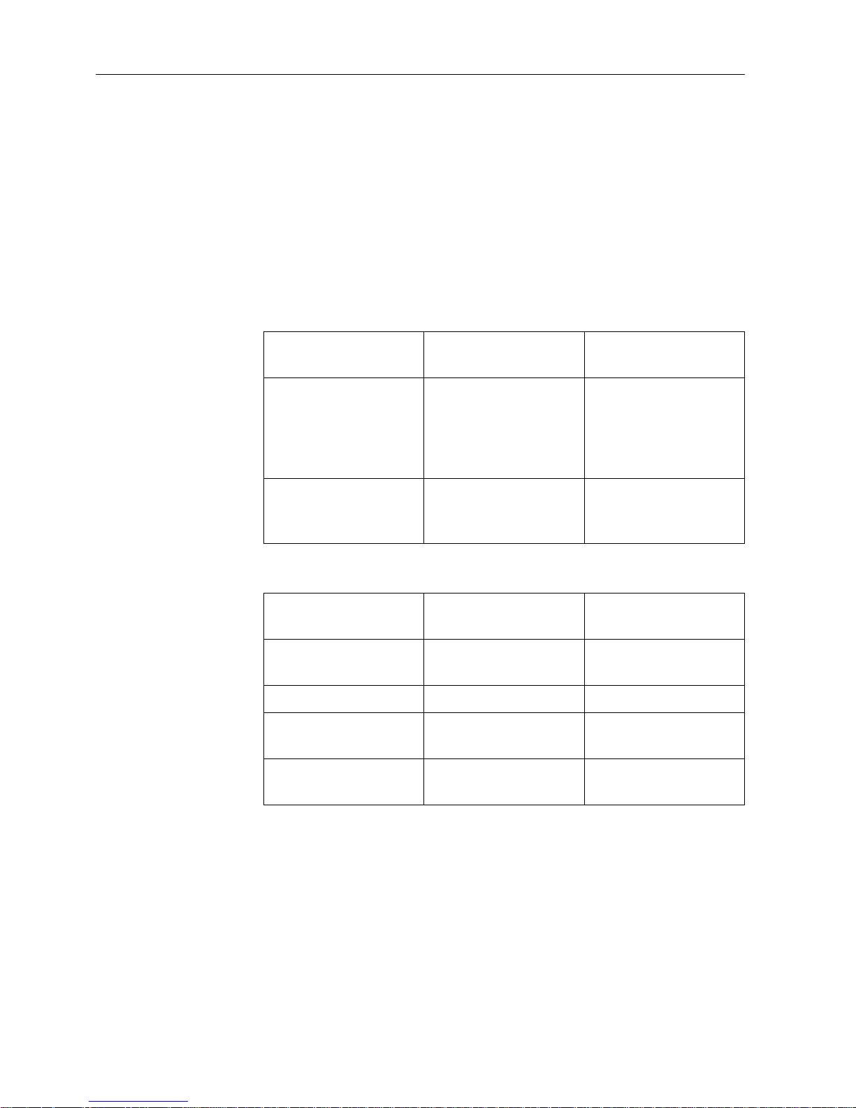
IND4x9 / BBA4x9 weighing terminals and compact scales
Power supply variants
Normal version
Explosion protected
version
Weighing terminals
IND429
IND439
IND449
IND439check
IND449check+
IND429xx
IND439xx
IND449xx
IND439xx
check
IND449xx
check+
Compact scales
BBA429
BBA439check
BBA449check+
–
Normal version
Explosion protected
version
Built-in power supply
unit
Standard Standard
Built-in storage battery Optional Optional
External power supply
12–24 V DC
Optional Optional
Via external storage
battery
Optional (BBA4x9) –
Page 5

Safety instructions
Installation information 22013821A 04/06 5
IND4x9 / BBA4x9
2 Safety instructions
2.1 Safety instructions for explosion protected weighing terminals
IND4x9xx
The device fulfils Device category 3 and is approved for operation in Zone 2 (gases)
and Zone 22 (dusts) hazardous areas.
There is an increased risk of injury and damage when used in hazardous areas.
Special care must be taken when working in such hazardous areas. The code of
practice is oriented to the "Safe Distribution" concept drawn up by METTLER TOLEDO.
Competence ▲ The device, accompanying weighing platforms and accessories may only be
installed, maintained and repaired by authorised METTLER TOLEDO service
personnel.
▲ The mains connection may only be connected or disconnected by the owner’s
electrician.
Ex approval ▲ For the exact specification please refer to the statement of conformity.
▲ No modifications may be made to the terminal and no repair work may be
performed on the modules. Any weighing platform or system modules that are
used must comply with the specifications contained in the installation instructions.
Non-compliant equipment jeopardizes the safety of the system, cancels the Ex
approval and renders any warranty or product liability claims null and void.
▲ The cable glands must be tightened so that a strain relief of ≥ 20 N per mm cable
diameter is ensured.
▲ Ensure that the supply voltage at the installation site amounts to 230 V.
▲ When connecting external devices, always observe the maximum permissible
connected loads, see Page
29. It must be ensured that no voltages are fed into
the device than it itself provides. The interface parameters have to fulfil the
standard.
▲ Peripheral devices without an Ex approval may only be operating in non-
hazardous areas. It must be ensured that no voltages are fed into the device than
it itself provides. In addition the maximum permissible connected loads have to
be observed, see Page
29. The interface parameters have to fulfil the standard.
▲ The safety of a weighing system is only guaranteed when the weighing system is
operated, installed and maintained in accordance with the respective
instructions.
▲ Also comply with the following:
– the instructions for the system modules
– the regulations and standards in the respective country
– the statutory requirement for electrical equipment installed in hazardous areas
in the respective country
– all instructions related to safety issued by the owner
▲ Before initial start-up and following service work, check the explosion-protected
weighing system for the proper condition of all safety-related parts.
Page 6

Safety instructions
6 Installation information 22013821A 04/06
IND4x9 / BBA4x9
Installation and
retrofitting
▲ Only install or perform maintenance work on the weighing terminal,
accompanying weighing platforms and accessories in the hazardous zone if the
following conditions are fulfilled:
– the owner has issued a permit ("spark permit" or "fire permit"),
– the area has been rendered safe and the owner's safety co-ordinator has
confirmed that there is no danger,
– the necessary tools and any required protective clothing are provided (danger
of the build-up of static electricity).
▲ The certification papers (certificates, manufacturer’s declarations) must be
present.
▲ Connection values of externally connectable devices and cables of other
manufacturers must be known, e.g. capacitances, inductances and current
consumption.
▲ Lay cables in such a way that they are protected from damage.
▲ Only route cables into the housing of the system modules via the earthing cable
gland or METTLER TOLEDO plug and ensure proper seating of the seals. Ensure
that the cable shields are connected correctly and that they have a secure
connection to the housing.
▲ If the device is used in conjunction with an automatic or manual filling plant, all
of the system modules must be equipped with a permanently wired emergency
stop circuit, independent of the system circuit, in order to prevent personal injury
or damage to other items of equipment.
▲ Establish an equipotential bonding.
▲ If the weighing platforms are installed in a pit, test whether primary explosion
protection is required.
▲ Cover unused connection sockets with protective caps.
▲ Mount the labelling for operation in hazardous areas, see Section 3.4.3.
▲ After connectors have been mounted, screw on the securing clamps for external
connectors.
Operation ▲ Prevent the build-up of static electricity. Therefore:
– Always wear suitable working clothes when operating or performing service
work on the system.
– Do not rub or wipe off the keyboard surface with a dry cloth or glove.
▲ Do not use protective hoods.
▲ Prevent damage to the weighing terminal. Hairline cracks in the keyboard
membrane are also considered damage.
▲ If the weighing terminal, accompanying weighing platforms or accessories are
damaged:
– Switch off the weighing terminal
– Separate the weighing terminal from the mains in accordance with the
applicable regulations
– Secure the weighing terminal against accidental start-up
▲ Always charge the storage batteries in a safe zone.
Page 7

Safety instructions
Installation information 22013821A 04/06 7
IND4x9 / BBA4x9
2.2 Safety instructions for non-explosion-protected devices
▲ Do not use the device in a hazardous environment!
Special devices are available in our range of products for hazardous
environments.
▲ Ensure that the power socket outlet for the device is earthed and easily
accessible, so that it can be de-energized rapidly in emergencies.
▲ Ensure that the supply voltage at the installation site lies within in the range of
100 V to 240 V.
▲ The safety of the device cannot be ensured if it is not operated in accordance with
these operating instructions.
▲ Only authorised personnel may open the device.
▲ Check the power cable regularly for damage. If it is damaged, disconnect the
device immediately from the power supply.
▲ Ensure that there is a space of at least 3 cm at the rear in order to prevent the
power cable from being bent too strongly.
Page 8
Commissioning
8 Installation information 22013821A 04/06
IND4x9 / BBA4x9
3 Commissioning
3.1 Connecting analog weighing platforms
Any analog weighing platforms that fulfil the required specifications can be connected
to weighing terminals with an analog weighing interface, see Section
7.2.
Weighing platforms for hazardous areas require the corresponding approval.
3.1.1 Information on the weighing cells
Weighing cells with or without SENSE cables
➜ In the case of cells without SENSE cables short-circuit the connections +Ex
(Excitation) and +Se (Sense) or –Ex and –Se at the connector or at the
connection terminal.
3.1.2 Connection of weighing platforms with several weighing cells
Up to four weighing cells can be connected to a weighing terminal in parallel. A
junction box is usually used to connect several weighing cells.
The sum of the nominal capacities of the individual cells corresponds to the total
capacity of the weighing system. When entering the scale capacities in the menu
(Section
4.4.5), select values in such a way that the individual cells cannot be
overloaded.
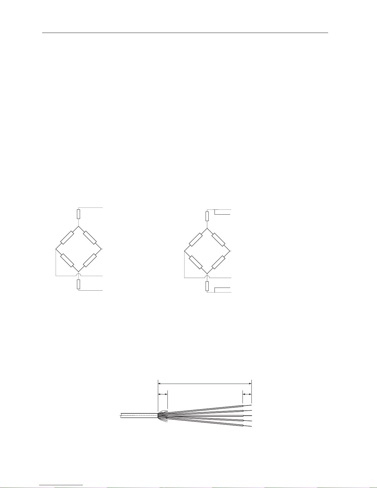
3.1.3 Preparation of the weighing platform connection cable
➜ Strip the cell cable in accordance with the figure.
+Si
+Se
+Ex
–Se
–Ex
–Si
+Si
+Se
+Ex
–Se
–Si
–Ex
Cells without SENSE cables
Cells with SENSE cables
required for certifiable weighing systems
15 mm
135 mm
5mm
Page 9

Commissioning
Installation information 22013821A 04/06 9
IND4x9 / BBA4x9
3.1.4 Connection of an analog weighing platform to the weighing terminal
The weighing terminals IND439 / IND439xx and IND449 / IND449xx can be
equipped with a second analog weighing interface.
The connection of a second weighing platform requires that a weighing platform
already be connected directly to the weighing terminal.
DANGER OF ELECTRIC SHOCK
➜ Disconnect the weighing terminal from the power supply before beginning
installation work.
Opening the weighing terminal and drawing in the weighing platform cable
1. In the case of explosion protected weighing terminals remove the plug protection
strip at the rear of the terminal.
2. Open the terminal. To do so, unscrew the hex bolts and lay the cover down.
When doing so, take care of the cable connections.
3. Remove the cable gland of the desired scale connection and the blind plugs from
the cable gland.
4. Slide the union nut (3) and moulded seal (2) over the cable sheathing. If any
braided screen cores loosen in the process, these may not contact any
conductive system parts.
5. Unbraid the exposed screen and place it evenly over the moulded seal (2).
6. Insert the moulded seal with the cable into the anti-twist guard of the metal
housing (1).
7. Screw the union nut onto the metal housing and tighten it.
Connecting the first analog weighing platform
1. Pull off the green 7-pin connector in the weighing terminal. The connector has a
tab that facilitates its removal and plugging.
2. Fasten the conductors of the connecting cable to the connector. The connector
assignment is shown in the adjacent figure.
The 7-pin connector has an additional connection in the middle for the signal
earth. The signal earth can optionally be applied to this connection or to the
screening and moulded seal (2).
When connecting METTLER TOLEDO weighing platforms observe the connection
scheme supplied with the weighing platform.
3. Plug the connector in the weighing terminal. Ensure that the connector sits
exactly centred on the socket. Otherwise not all the pins contact.
1
2
3
+Ex +Se +Si -Si-Se -Ex
Si = Signal
Ex = Excitation
Se = Sense
Page 10

Commissioning
10 Installation information 22013821A 04/06
IND4x9 / BBA4x9
Connecting the second analog weighing platform
(only IND439 / IND439xx and IND449 / IND449xx)
➜ Connect the conductors of the connecting cable to the 7-pin terminal block on the
second analog PCB. The terminal assignment is shown in the adjacent figure.
The 7-pin terminal block has an additional connection in the middle for the
signal earth. The signal earth can optionally be applied to this connection or to
the screening.
When connecting METTLER TOLEDO weighing platforms observe the connection
scheme supplied with the weighing platform.
Note • In the factory setting the second scale is configured as a quantity scale (BULK).
REF (reference scale) or AUXILIARY (auxiliary scale) can be selected instead in the
COMMUNICATION –> OPTION –> MODE interface menu. The BYPASS setting can
be used to de-activate the weighing platform.
• Subsequently calibrate the second analog weighing platform (SCALE 2).
Closing the terminal
1. Position the cover and screw on the hex bolts. Ensure that no cables are pinched
and that the cover sealing ring is positioned correctly.
2. Tighten the union nut of the heavy-gauge screw joint(s).
3. In the case of explosion protected weighing terminals mount the plug protection
strip over the connections at the rear of the terminal.
3.2 Connecting IDNet weighing platforms
Alternatively to the analog scale connection the weighing terminals can also be
equipped with IDNet scale interfaces. At IND439/IND439xx and IND449/IND449xx a
second IDNet weighing platform can be connected optionally.
Information about two-scales systems
The scale with the higher address is defined by the weighing terminal as the second
scale, irrespective of the socket to which the scale is connected. When brand new
scales are commissioned, the weighing terminal automatically assigns an address.
If an IDNet scale already has an address, this can be reset in the scale service mode
(RES ALL). In the process the ID code is increased at certified scales.
–Ex –Se –Si +Si +Se +Ex
Page 11

Commissioning
Installation information 22013821A 04/06 11
IND4x9 / BBA4x9
Procedure
1. Set up the (first) weighing platform, refer to the installation instructions of the
weighing platform.
2. Lay the weighing platform cable to the weighing terminal.
3. Ensure that the weighing terminal is switched off.
4. In the case of explosion protected devices remove the plug protection strip at the
rear.
5. Plug the weighing platform connector into the weighing terminal and tighten the
screws.
6. Switch on the weighing platform. This weighing platform has the scale number 1.
7. If necessary, repeat Steps 1 to 6 for the second scale. Scale number 2 is
assigned to the second scale.
8. In the case of explosion protected devices mount the plug protection strip over the
connections at the rear.
Note In the factory setting the second scale is configured as a quantity scale (BULK). REF
(reference scale) or AUXILIARY (auxiliary scale) can be selected instead in the
COMMUNICATION –> OPTION –> MODE interface menu. The BYPASS setting can be
used to de-activate the weighing platform.
3.3 Setting up the compact scale
1. Set up the compact scale at the desired installation site.
2. Level the compact scale; refer to the PBA430 weighing platform operating
instructions.
Page 12

Commissioning
12 Installation information 22013821A 04/06
IND4x9 / BBA4x9
3.4 Particular points when commissioning explosion protected
weighing terminals
3.4.1 Equipotential bonding
The equipotential bonding must be installed by a professional electrician when using
the weighing platforms in hazardous areas.
➜ Connect equipotential bonding of all devices in accordance with the country-
specific regulations and standards. In the process, make sure that all device
housings are connected to the same potential via the PA terminals.
Weighing terminal
equipotential bonding
terminal
The equipotential bonding clamp of the weighing terminal is found on the COM1
socket.
3.4.2 Limited mobility
EXPLOSION HAZARD
The device may only be operated in Zone 2 and 22 hazardous areas.
Cabling
➜ Protect data and signal cable extensions against inadvertent disconnection.
➜ Secure the interface connections on the rear using the plug protection strip.
3.4.3 Labelling for operation in a hazardous area
The following signs must be mounted on the weighing terminal, accompanying
weighing platforms and accessories so that they are clearly visible:
• Model plate with the device’s model data, manufacturer and serial number
• Safety instructions
• Explosion protection identification
• If appropriate, temperature range
3.5 Connecting devices with a 12–24 V DC supply
Explosion protected IND429xx weighing terminals are supplied with a fixed-mounted
2.5 m long connecting cable with open ends.
Non-explosion-protected devices are equipped with a socket for connecting the power
supply. A connecting cable with open ends is included with the device.
Connected values 12 V DC – 24 V DC, max. 800 mA
Connection end Open ends
Colour code Brown – plus
White – minus
Page 13

Scale configuration
Installation information 22013821A 04/06 13
IND4x9 / BBA4x9
4 Scale configuration
4.1 Calling up the service menu
4.1.1 At non-certifiable analog scales and IDNet scales
1. Press and hold until COdE appears.
2. Enter the service password .
The SCALE menu item is displayed.
Note
Access to the service menu is secured by means of a software seal (ID code) at
IDNet scales. If changes are carried out at a scale that is set to certifiable, the ID code
is increased by 1 and stored in the scale. After configuration has been terminated, the
ID code at the connector of the scale has to be set to the same value as the stored
one. This setting has to be stored by certifiable means.
4.1.2 At certifiable analog scales
Due to metrological regulations direct access to the service menu (technician mode)
is blocked at certified or certifiable scales. The calibration seal is destroyed when the
device is opened. After the configuration has been completed, the device has to be
recalibrated by an authorised company and a new calibration seal attached before it
may be used again as a calibrated scale.
DANGER OF ELECTRIC SHOCK
The power supply unit under the power supply unit cover is energized.
➜ Do not carry out service work on the power supply unit and mains cable.
Procedure
1. Devices with power connection: Disconnect from the power supply. Devices with
storage battery: Switch off.
2. Open the housing cover.
3. Remove the cover and set it down or fix it. When doing so, take care of the cable
connections.
4. Devices with power connection: Connect to the power supply. Devices with
storage battery: Switch on.
5. Press the Pushbutton 1 on the PCB of the first scale interface. Use a suitable tool
to this purpose, for example, the blunt end of a pencil.
The device starts up and the first block of the SCALE servicemenu is displayed.
6. Replace the cover and carry out the service settings.
7. After the settings have been completed, disconnect the power plug again at
devices with a power connection.
8. Close the housing cover with the hex bolts. Ensure proper seating of the cover
sealing ring when doing so.
1
Page 14

Scale configuration
14 Installation information 22013821A 04/06
IND4x9 / BBA4x9
4.2 Overview
After the service menu has been called up, the entire menu is available, also the user
and supervisor menu. The following overview shows the SCALE menu block, the
remaining menu is described in the operating instructions.
Note
Only the menu blocks in bold are displayed at IDNet scales. At IDNet scales the
service mode of the scale is shown after SCALE (1/2) has been selected. The query
rEtUrN? appears. With
SNr is displayed as the next menu item.
4.3 Service menu operation
Operation in the service menu is the same as in the user and supervisor menu.
Numerical values, for example capacity, can be entered via the numerical keypad, if
present.
Numerical input at devices without number block
1. Press the key in order to activate the input.
The first number begins to flash.
2. Change the number using the and keys.
3. Confirm the modified number with the key.
The next number begins to flash.
4. Repeat Steps 2 and 3 until all the numbers have been entered.
Block Meaning Page
SCALE MEtrOLO Determining the admissibility for certification 15
SCALE 1 /
SCALE 2
Selection of the scale to be configured, is only displayed at two-scale
systems
15
rAMP Display of the excursion of the A/D converter (ramp) 15
SNr Query/Modification of the serial number 15
SCAL.bLd Input of the configuration data 16
GEO Setting of the Geo value 16
LIN-CAL Linearization with calibration 18
CAL Basic calibration 18
CONtrOL Activation of the control mode 18
ZErO Settings for the zero point 19
Min.WEiG Setting the minimum weighing-in quantity 19
T
T
Page 15

Scale configuration
Installation information 22013821A 04/06 15
IND4x9 / BBA4x9
4.4 Description of the service menu
4.4.1 Admissibility for certification
4.4.2 SCALE1/SCALE2 – Selecting a scale
This menu item appears only if a second scale or weighing platform is connected.
4.4.3 Querying the value of the A/D converter
4.4.4 Querying the serial number of the terminal or compact scale
MEtrOLO Setting the admissibility for certification
NO APPr Scale not certifiable
OIML Certify scale to OIML
ntEP Certify scale to NTEP, valid for the USA
Note If a scale is certified, various scale settings are no longer available or are only
available to a limited extent. Direct access to the menu for service personnel is,
furthermore, blocked subsequently.
rAMP
rMP 20 Display of the percentage deflection of the analog/digital converter (ramp)
Note This value can be used to determine whether the weighing cell operates correctly.
Scales with identical and a weighing cell that functions correctly have more or less
the same ramp values. The value is dynamic and changes when the load changes.
SNr
1234567 Display or modification of the serial number.
Note The serial number should not be changed except, for example, after a new main
printed circuit board has been installed.
Page 16

Scale configuration
16 Installation information 22013821A 04/06
IND4x9 / BBA4x9
4.4.5 Entering configuration data
4.4.6 Setting the Geo value
SCAL.bLd Input of the configuration data
SCAL.tYP Defining the scale type
SINGLE.r Single Range: Single-range scale
2MULt.IN Multi interval: Scale with rough range and 1 shiftable fine range.
Automatic switching between the ranges in both directions.
2MULt.rN Multi Range: Scale with rough range and 1 fixed fine range.
Automatic change to the rough range. Return to the fine range at
zero pass.
3MULt.IN Multi Interval: Scale with rough range and 2 shiftable fine ranges
3MULt.rN Multi Range: Scale with rough range and 2 fixed fine ranges.
bAS.UNIt Specify the basic unit for entering in the service menu
g Grams
kg Kilograms
oz Ounces
lb Pounds
t Tons
SCL.CAP Entry of the scale capacity in the selected basic unit
rESOL Selection of the resolution in the selected basic unit
The available resolutions depend on the capacity of the weighing system.
Note In case of multi-range or multi-interval scales the blocks SCL.CAP and rESOL
are available separately for each range.
They are displayed in the following sequence:
SCL.CAP 1, rESOL 1, SCL.CAP 2, rESOL 2, SCL.CAP 3, rESOL 3
GEO The Geo value is used to adapt the weighing system to the local gravity conditions.
0 ... 31 Setting range: 0 ... 31, see following table
Page 17

Scale configuration
Installation information 22013821A 04/06 17
IND4x9 / BBA4x9
Table of Geo values
Northern or southern latitude in degrees and minutes
Height above sea level in meters
0
325
325
650
650
975
975
1300
1300
1625
1625
1950
1950
2275
2275
2600
2600
2925
2925
3250
3250
3575
Height above sea level in feet
0
1060
1060
2130
2130
3200
3200
4260
4260
5330
5330
6400
6400
7460
7460
8530
8530
9600
9600
10660
10660
11730
0° 0’ – 5° 46’ 5 4 4 3 3 2 2 1 1 0 0
5° 46’ – 9° 52’ 5 5 4 4 3 3 2 2 1 1 0
9° 52’ – 12° 44’ 6 5 5 4 4 3 3 2 2 1 1
12° 44’ – 15° 6’ 6 6 5 5 4 4 3 3 2 2 1
15° 6’ – 17° 10’ 7 6 6 5 5 4 4 3 3 2 2
17° 10’ – 19° 2’ 7 7 6 6 5 5 4 4 3 3 2
19° 2’ – 20° 45’ 8 7 7 6 6 5 5 4 4 3 3
20° 45’ – 22° 22’ 8 8 7 7 6 6 5 5 4 4 3
22° 22’ – 23° 54’ 9 8 8 7 7 6 6 5 5 4 4
23° 54’ – 25° 21’ 9 9 8 8 7 7 6 6 5 5 4
25° 21’ – 26° 45’ 10 9 9 8 8 7 7 6 6 5 5
26° 45’ – 28° 6’ 10 10 9 9 8 8 7 7 6 6 5
28° 6’ – 29° 25’ 11 10 10 9 9 8 8 7 7 6 6
29° 25’ – 30° 41’ 11 11 10 10 9 9 8 8 7 7 6
30° 41’ – 31° 56’ 12 11 11 10 10 9 9 8 8 7 7
31° 56’ – 33° 9’ 12 12 11 11 10 10 9 9 8 8 7
33° 9’ – 34° 21’ 13 12 12 11 11 10 10 9 9 8 8
34° 21’ – 35° 31’ 13 13 12 12 11 11 10 10 9 9 8
35° 31’ – 36° 41’ 14 13 13 12 12 11 11 10 10 9 9
36° 41’ – 37° 50’ 14 14 13 13 12 12 11 11 10 10 9
37° 50’ – 38° 58’ 15 14 14 13 13 12 12 11 11 10 10
38° 58’ – 40° 5’ 15 15 14 14 13 13 12 12 11 11 10
40° 5’ – 41° 12’ 16 15 15 14 14 13 13 12 12 11 11
41° 12’ – 42° 19’ 16 16 15 15 14 14 13 13 12 12 11
42° 19’ – 43° 26’ 17 16 16 15 15 14 14 13 13 12 12
43° 26’ – 44° 32’ 17 17 16 16 15 15 14 14 13 13 12
44° 32’ – 45° 38’ 18 17 17 16 16 15 15 14 14 13 13
45° 38’ – 46° 45’ 18 18 17 17 16 16 15 15 14 14 13
46° 45’ – 47° 51’ 19 18 18 17 17 16 16 15 15 14 14
47° 51’ – 48° 58’ 19 19 18 18 17 17 16 16 15 15 14
48° 58’ – 50° 6’ 20 19 19 18 18 17 17 16 16 15 15
50° 6’ – 51° 13’ 20 20 19 19 18 18 17 17 16 16 15
51° 13’ – 52° 22’ 21 20 20 19 19 18 18 17 17 16 16
52° 22’ – 53° 31’ 21 21 20 20 19 19 18 18 17 17 16
53° 31’ – 54° 41’ 22 21 21 20 20 19 19 18 18 17 17
54° 41’ – 55° 52’ 22 22 21 21 20 20 19 19 18 18 17
55° 52’ – 57° 4’ 23 22 22 21 21 20 20 19 19 18 18
57° 4’ – 58° 17’ 23 23 22 22 21 21 20 20 19 19 18
58° 17’ – 59° 32’ 24 23 23 22 22 21 21 20 20 19 19
59° 32’ – 60° 49’ 24 24 23 23 22 22 21 21 20 20 19
60° 49’ – 62° 9’ 25 24 24 23 23 22 22 21 21 20 20
62° 9’ – 63° 30’ 25 25 24 24 23 23 22 22 21 21 20
63° 30’ – 64° 55’ 26 25 25 24 24 23 23 22 22 21 21
64° 55’ – 66° 24’ 26 26 25 25 24 24 23 23 22 22 21
66° 24’ – 67° 57’ 27 26 26 25 25 24 24 23 23 22 22
67° 57’ – 69° 35’ 27 27 26 26 25 25 24 24 23 23 22
69° 35’ – 71° 21’ 28 27 27 26 26 25 25 24 24 23 23
71° 21’ – 73° 16’ 28 28 27 27 26 26 25 25 24 24 23
73° 16’ – 75° 24’ 29 28 28 27 27 26 26 25 25 24 24
75° 24’ – 77° 52’ 29 29 28 28 27 27 26 26 25 25 24
77° 52’ – 80° 56’ 30 29 29 28 28 27 27 26 26 25 25
80° 56’ – 85° 45’ 30 30 29 29 28 28 27 27 26 26 25
85° 45’ – 90° 00’ 31 30 30 29 29 28 28 27 27 26 26
Page 18

Scale configuration
18 Installation information 22013821A 04/06
IND4x9 / BBA4x9
4.4.7 Linearization with simultaneous calibration
4.4.8 Basic calibration
4.4.9 Activating the control mode
LIN-CAL A basic calibration must have been carried out at least once for linearization with
simultaneous calibration.
➜ If available, apply the preload.
3 POINt /
5 POINt
• 3-point linearization (by default at 0 %, 50 % and 100 % of the full load)
• 5-point linearization (by default at 0 %, 25 %, 50 %, 75 % and 100 % of the
full load)
1. Confirm the type of linearization.
The display begins to flash, the scale determines the zero point automatically.
The scale next requests the first weight.
2. If appropriate, change the displayed weight value.
3. Place the displayed weight on the scale and confirm with .
4. Repeat Steps 2 and 3 for each additional sample.
After all the weights have been applied, donE is displayed.
Notes
• Determining the zero point can be skipped by pressing . In this case the
existing zero point is used as the reference.
• Linearization/calibration can be cancelled at any time with the key.
T
CAL Calibration can be carried out with preload in basic calibration.
PrELOAd
1. Load the desired preload and confirm with .
The scale next requests the calibration weight corresponding to the full load.
2. If appropriate, change the displayed weight value.
3. Place the displayed weight on the scale and confirm with .
After calibration has been carried out, donE is displayed.
Notes
• Determining the preload can be skipped with . In this case the existing zero
point is used as the reference.
• Calibration can be cancelled at any time with the key.
• In order to achieve particularly high precision carry out calibration under full
load.
T
CONtrOL In control mode the current weighing result is displayed with a high resolution and
without a weight unit. This allows the scale to be checked, for example after
calibration and/or linearization.
Page 19

Scale configuration
Installation information 22013821A 04/06 19
IND4x9 / BBA4x9
4.4.10 Settings for the zero point
4.4.11 Specifying the minimum weighing-in quantity
ZErO Settings for the zero point
Z-CAPt Specify the zero capturing range
-2 18 Zero capturing range –2 % to +18 %
–2 2 Zero capturing range –2 % to +2 %, mainly for certifiable scales
SEt.ZErO Move the calibration zero point. This is necessary if an auxiliary preload is used or
if the preload (for example roller conveyor) cannot be used for calibration or if they
lie outside the zero capturing range.
1. Apply the preload and confirm with .
The query SUrE is displayed.
2. Confirm moving of the zero point with or cancel with .
3. If underload or overload is displayed after the menu has been exited, switch the
device off and on again.
AZM Setting for the automatic zero compensation mode, refer to the operating
instructions.
Note The zero capturing range limits the nominal capacity of the scale. If the capacity of
a weighing cell is to be used to its complete extent, the zero capturing range can be
limited to –2 % to +2 %.
T
Min.WEiG Entry of the minimum weighing-in quantity in the selected basic unit.
When the minimum weighing-in quantity is activated, * is displayed if the weight on
the scale falls below the stored minimum weight.
Page 20

Commissioning and configuration of the interfaces
20 Installation information 22013821A 04/06
IND4x9 / BBA4x9
5 Commissioning and configuration of the interfaces
5.1 Configuration and testing of the Ethernet interface
5.1.1 Configuration of the Ethernet interface in the menu of IND4x9 / BBA4x9
The configuration of the Ethernet interface in the menu is described in the operating
instructions (COMMUNI –> OPTION –> ETHERNET).
Ask your network administrator for the correct settings for the IP address, subnet
mask and gateway.
5.1.2 Establishing a network connection between the Ethernet interface and the PC
If the PC is already connected via a switch/hub to the network, no further settings are
required for the network card in the PC.
In the case of a direct connection between the Ethernet interface and the PC via a
cross-patch cable the settings for the TCP/IP Internet protocol have to be observed.
1. Call up Start –> Control Panel –> Network Connection.
2. Select "Local Area Connection" and right-click it to select "Properties".
3. Select "Internet Protocol (TCP/IP)" and click "Properties".
4. Enter the IP address, subnet mask and gateway in accordance with the settings
in the menu.
5.1.3 Testing the Ethernet interface
The "Ping" command can be used to check whether a user exists in the network and
can also be addressed.
1. Open a DOS box (command prompt) at the PC (Start –> Run).
2. Enter the "Ping" command followed by the IP address at the weighing terminal or
compact scale.
With the default address the command is as follows: Ping 192.168.1.1
3. The answer is, for example, Bytes = 32, Time = 2 ms, TTL = 64.
If no response appears, repeat the command with correct entries.
5.1.4 Establishing a connection with HyperTerminal
1. Select the DIALOG setting for the Ethernet interface in the menu under COMMUNI
–> COM2 –> MODE.
2. Start HyperTerminal and create a new connection.
3. Select "TCP/IP (Winsock)", specify the IP address of the Ethernet interface
(factory setting: 192.168.1.1) enter the port number (factory setting: 8000).
4. Select the following settings under "File –> Properties –> Settings –> ASCII
Configuration":
– Transmitted characters end with line feed
– Output entered characters locally (local echo)
– Write lines that are too long in the terminal window
SICS commands can now be transmitted at the weighing terminal or compact scale.
Page 21

Commissioning and configuration of the interfaces
Installation information 22013821A 04/06 21
IND4x9 / BBA4x9
5.1.5 Configuration of the Ethernet interface via a Web browser
The Ethernet interface is equipped with a Web server through which the further
settings can be carried out.
1. Start a Web browser on the PC, for example Internet Explorer, and enter "http://
192.168.1.1" as the target address.
The starting page of the Ethernet Web server is displayed.
2. Use the "Client Server –> Help" menu item to call up further information on setting
the Ethernet interface.
5.2 Installing the drivers for the USB interface
For weighing terminals or compact scales with a USB interface a CD with the required
drivers is provided additionally. The drivers are installed in two steps.
The following section describes the installation for a PC with Windows XP.
5.2.1 Installing USB drivers
1. Connect the USB interface of the weighing terminal or compact scale to the PC
with a USB cable.
The message "New hardware found" is displayed at Windows XP.
2. Insert the supplied CD into the PC.
The wizard for searching for new hardware is displayed.
3. Select "Install software from a list or specific location (for advanced users)" in the
initial screen and click "Next".
4. In the next step select "Browse removable media (floppy disk, CD, etc.)" and
click "Next".
The required files are searched for and copied.
A warning is displayed since the drivers on the CD ROM have not been certified by
Microsoft WHQL. However, the drivers were tested extensively by METTLER TOLEDO
and are suitable for installation under Windows XP.
5. Click "Continue Anyway".
6. Click "Finish" in the next screen.
The installation is completed. The message "New hardware found" is displayed.
Subsequently The VCP driver still has to be installed subsequently.
5.2.2 Installing VCP drivers
The wizard for searching for new hardware is displayed again.
➜ Repeat Steps 3 to 6 as described under Section 5.2.1 for the VCP driver.
Page 22

Commissioning and configuration of the interfaces
22 Installation information 22013821A 04/06
IND4x9 / BBA4x9
5.2.3 Setting the Virtual COM Port (VCP)
The installation of the VCP driver makes an additional serial interface available on the
PC. This interface can be used to access weighing terminals or compact scales with
a USB interface.
1. Call up "Start –> Control Panel" and double-click "System".
2. Select the "Hardware" tab and click the "Device Manager".
3. Search for the entry "Ports (COM & LPT)" and click the adjacent "+" symbol.
All the available ports are displayed.
4. Double-click "METTLER TOLEDO Serial Port".
The "Properties of METTLER TOLEDO Serial Port" screen is displayed.
5. Select the "Port settings" tab and click "Advanced".
6. Select the desired COM port number from the drop-down menu list and confirm
with "OK".
5.2.4 Establishing a connection with HyperTerminal
1. Select the DIALOG setting for the USB interface in the menu under COMMUNI –>
COM2 –> MODE.
2. Start HyperTerminal and create a new connection.
3. Select the desired COM port number and carry out the following settings:
9600 bits/s, 8 data bits, no parity, protocol Xon/X0ff.
4. Select the following settings under "File –> Properties –> Settings –>
ASCII Configuration":
– Transmitted characters end with line feed
– Output entered characters locally (local echo)
– Write lines that are too long in the terminal window
SICS commands can now be transmitted at the weighing terminal or compact scale.
5.3 Configuration of the WLAN interface
The following section describes the installation for a PC with Windows XP. It is
assumed that the WLAN interface of the weighing terminal or compact scale is in the
state of delivery with the following network parameters:
IP address 192.168.0.1
Subnet 255.255.255.0
Gateway 0.0.0.0
5.3.1 Configuration of the WLAN interface in the menu of IND4x9 / BBA4x9
The configuration of the WLAN interface in the menu is described in the operating
instructions (COMMUNI –> OPTION –> WLAN).
Ask your network administrator for the correct settings for the IP address, subnet
mask and gateway in the encrypted company network.
Page 23

Commissioning and configuration of the interfaces
Installation information 22013821A 04/06 23
IND4x9 / BBA4x9
5.3.2 Establishing an ad-hoc connection to the WLAN network
1. Ensure that the weighing terminal or the compact scale with the WLAN interface
is switched off.
2. Call up the WLAN configuration program on the PC and carry out the following
settings.
– Set the SSID to "Connect".
– Select no encryption.
– Set the parameters for the ad-hoc connection: 2.4 GHz, 11 Mbps.
– Ensure that a free channel is used or that the channel is selected automatically.
– Ensure that no WLAN connection is active.
3. Ensure that no further network connections are active, for example LAN
connection via Ethernet cable.
4. Call up Start –> Control Panel –> Network Connection.
5. Select "Wireless Network Connection" and click "Internet Protocol (TCP/IP)".
6. Click "Properties" and carry out the following settings:
– Set the IP address 192.168.0.10.
A different IP address can also be selected in the subnet 192.168.0.x. The IP
address of the weighing terminal or compact scale with WLAN interface
(192.168.0.1) may not be selected.
– Subnet mask: 255.255.255.0.
– No gateway setting
7. Call up the WLAN configuration program on the PC and activate the WLAN
connection.
8. Switch on the weighing terminal or compact scale with WLAN interface.
The WLAN interface is equipped with a Web server through which the further settings
can be carried out.
5.3.3 Configuration via Web browser
1. When an active ad-hoc connection is displayed at the PC, start a Web browser
on the PC, for example the Internet Explorer.
2. Enter the target address "http://192.168.0.1".
The log-on page of the WLAN Web user interface is displayed.
3. Log on with the user name "admin" and the password "admin".
4. Carry out the network settings for the encrypted company network under
Configuration –> Network.
Page 24

Commissioning and configuration of the interfaces
24 Installation information 22013821A 04/06
IND4x9 / BBA4x9
5.3.4 Establishing a connection with HyperTerminal
1. Select the DIALOG setting for the WLAN interface in the menu under COMMUNI –>
COM2 –> MODE.
2. Start HyperTerminal and create a new connection.
3. Select "TCP/IP (Winsock)", specify the IP address of the WLAN interface (factory
setting: 192.168.0.1) and enter the port number (factory setting: 2101).
4. Select the following settings under "File –> Properties –> Settings –> ASCII
Configuration":
– Transmitted characters end with line feed
– Output entered characters locally (local echo)
– Write lines that are too long in the terminal window
SICS commands can now be transmitted at the weighing terminal or compact scale.
Page 25

Structure of an analog weighing system
Installation information 22013821A 04/06 25
IND4x9 / BBA4x9
6 Structure of an analog weighing system
6.1 Selection of the weighing cell(s)
The following data are required to determine the capacity of the weighing cell:
• Scale capacity – Usually corresponds to the heaviest weighing sample that is to
be weighed using the weighing system.
• Preload – Contains the total weight of all the parts that lie on the weighing cell.
These include the top section of the weighing platform, the weighing pan and all
the assemblies, such as a roller conveyor, weighing vessel etc.
• Total zero setting range – Consists of the desired activation zero capturing range
(+18/–2 % or +/–2 %) and the zero setting range available to the user through
the
key (2 %). The total zero-set range thus amounts to either 20 % or 4 %
of the scale capacity.
The addition of the scale capacity, preload and total zero setting range results in the
required capacity of the weighing cell. It is advisable to include an additional safety
margin in order to avoid overloading of the weighing cell.
.
In the case of systems with several weighing cells divide the determined total
capacity by the number of cells in order to determine the capacity of the individual
cell. A sufficiently large safety margin is particularly important if a strong load is to be
expected in the corner areas of the scale so that the load is no longer distributed
evenly amongst all the cells.
In the case of systems with a lever mechanism divide the determined total capacity
by the transmission ratio of the lever mechanism in order to determine the capacity of
the individual cell.
Take the following further parameters into consideration when selecting the weighing
cell(s):
• The smallest desired display step
• Requirements for admissibility for certification, if necessary
• Number and type of the weighing ranges
• The approval for hazardous areas in the case of explosion protected weighing
systems
Total capacity of the weighing cell(s) = Scale capacity + Preload + Total zero setting range + Safety margin
Page 26

Structure of an analog weighing system
26 Installation information 22013821A 04/06
IND4x9 / BBA4x9
The terminal provides a supply voltage of 8.2 V for the weighing cell(s). Depending
on the sensitivity of the weighing cell this results in the following maximum weighing
signal (product of supply voltage and sensitivity):
* Only 20 mV can be measured by the A/D converter. Therefore the max. weighing
capacity may not exceed 81 % of the cell capacity.
Sensitivity of the cell 2 mV/V 3 mV/V
Supply voltage 8.2 V 8.2 V
Max. weighing signal * 16.4 mV 24.6 mV *
Min. weighing signal per display step (for certifiable scales) 0.5 µV/e 0.5 µV/e
Page 27

Structure of an analog weighing system
Installation information 22013821A 04/06 27
IND4x9 / BBA4x9
How do I set up my
scale?
Scale parameters:
– heaviest weight?
– weight of pan holder?
– smallest display step?
– certified scale?
– 1 or 2 ranges/intervals?
Required cell capacity
E
min
=
Max + E
0
+
Max* E
N
100
N
Data of weighing cell
Example A:
OIML R60: C3
E
max
(=E): 10 kg
n
LC
(=n): 3000
V
min
:E
max
/7500
C
N
(=S): 2 mV/V
Data of weighing cell
Example B:
OIML R60: C3/30%
R.C. (=E): 10 kg
(–> n: 3000)
(–> V
min
:E
*
30%/ n
R.O. (=S): 2 mV/V
Data of weighing cell
Example C:
OIML R60: C3
E
max
(=E): 550 kg
n
LC
(=n): 3000
V
min
: 0.01%* C
n
Cn (=S): 1.94 mV/V
Check
(in case of several weighing
ranges check the finest one)
0.5 µV
e
=
U
min
e
U
e
* S*
Max* 1000
n* E* N
>=
Data of terminal
(acc. to certification)
U
e
:8.2V
U
min
: 0.5 µV/e
n
max
: 7500e
Entries in menu block
“SCALE”
Max – > SCL.CAP
E
N
–> 2 - CAPt
V
min
–> RESOL.
Key:
Max [kg]: weighing range
N: no. of weighing cells
E
0
[kg]: preload (weight of pan holder, container, etc.)
E
N
[%]: zero setting range (2%) + zero capturing
range
(+18/–2% or ±2%) = 20% or 4%
E
min
[kg]: required load capacity per weighing cell
U
e
[V]: power supply from terminal
S [mV/V]: cell output signal
n [e]: resolution
E [kg]: load capacity of selected weighing cell
U
min
[µV/e]: minimum voltage per verification interval
n
max
[e]: maximum resolution
V
min
[g]: display step
Application
– simple weighing IND429/IND429xx
– simple counting IND439x/IND439xx
– simple IND439check/
checkweighing IND439xx check
– convenient counting IND449/IND449xx
– convenient IND449check/
checkweighing IND449xx check
– 2 scale counting
system Analog option
Page 28

Structure of an analog weighing system
28 Installation information 22013821A 04/06
IND4x9 / BBA4x9
6.2 Measurement range of the terminals
When designing a weighing system observe the measurement range of the terminal
in accordance with the following overview.
a Total preload applied to the weighing cell during calibration (platform top
section, weighing pan, roller conveyor, etc.)
b Activation zero capturing range: +18/–2 % or +/–2 % of the weighing
capacity, can be selected in the menu
c Zero setting range with 0 key: +/–2 % of the scale capacity, cannot be
modified
d Safety margin
a b Scale capacity d
0% 100%
0% 100%
–4mV 0mV 16,4mV 20 mV
Total capacity of weighing cell(s)
Deflection of the A/D converter ("Ramp")
Weighing cell signal, range of A/D converter
c
Page 29

Technical data
Installation information 22013821A 04/06 29
IND4x9 / BBA4x9
7 Technical data
7.1 General technical data
Mains connection Direct connection to power supply (supply voltage fluctuation not exceeding ±10 %
of the rated voltage)
• Non-explosion-protected weighing terminals IND4x9:
Rated voltage 100 ... 240 V AC / 47 ... 63 Hz / 300 mA
• Explosion protected weighing terminals IND4x9xx:
Rated voltage 230 V AC ±10 % / 47 ... 63 Hz / 300 mA
• Compact scales BBA4x9:
Rated voltage 100 ... 240 V AC / 47 ... 63 Hz / 300 mA
Storage battery operation Supply at device: 24 V DC / 1.0 A
If the supply voltage is interrupted, the scale switches automatically over to storage
battery operation
For operating life refer to the operating instructions
Ignition protection type
IND4x9xx
(to IEC 60079-15)
• Hazardous area Zone 2:
Device category II 3G EEx nA II T4,
Temperature range
–10 °C ... +40 °C / 14 °F ... 104 °F
• Hazardous area Zone 22:
Device category II 3D IP66 T 70 °C
Ambient conditions • Application
•Height
• Temperature range Class III
• Temperature range Class II
• Overvoltage category
• Degree of soiling
• Relative humidity
In interiors
up to 2,000 m
–10 ... +40 °C / 14 ... 104 °F
0 ... +40 °C / 32 ... 104 °F
II
2
up to max. 80 %, non-condensing
Interfaces
• 1 RS232 interface integrated
• 1 further optional interface possible
Max. permissible connected
values
• The total of the connected values of COM1 and COM2 may not exceed 100 mA
• At an installed Ethernet option COM1 may not exceed 50 mA
Page 30

Technical data
30 Installation information 22013821A 04/06
IND4x9 / BBA4x9
7.2 Technical data of the analog scale interface
Calculation example for the differential signal
Data of the weighing cell: Sensitivity 2 mV/V, cell capacity 100 kg
Differential signal for nominal load (60 kg)
2 mV/V * 8.2 V * 60 kg/100 kg = 9.84 mV
Differential signal for half load (30 kg)
2 mV/V * 8.2 V * 30 kg/100 kg = 4.92 mV
Prerequisites for certifiable scales
• Certifiable weighing cell with SENSE cables (6 leads),
Sensitivity of the cells 2 mV/V or 3 mV/V
• Scale configured in the Service menu as certifiable
• Labelling in accordance with regulations by the plant engineer, if the complete
scale was not supplied by METTLER TOLEDO
Analog scale interface
Resolution 300,000 points for non-certifiable applications
7,500 points for certifiable applications
Weighing ranges Up to 3 weighing ranges can be defined in the menu, incl. shiftable or fixed fine
ranges.
In the case of certifiable/certified applications the minimum voltage per calibration
value (0.5 µV/e) has to be ensured or 7,500 e may not be exceeded.
Calibration Basic calibration and calibration during linearization
Zero setting range (key) 2 % of the defined max. useable load, cannot be modified
Autozero range 2 % of the defined max. useable load, cannot be modified
Activation zero-set
range
–2 % ... 18 % or –2 % ... 2 % referenced to the defined max. useable load
can be selected in the menu
Linearity 0.01 % of the defined max. useable load
Units g, kg, oz, lb, t
Numerical steps
n
1, 2, 5 x 10n, can be selected in the menu
Cell power supply 8.2 V
Requirements for the weighing cell
Nominal load 0.1 ... 999,999.9 (g, kg, lb, oz, t)
Permissible impedance ≥ 80 Ω
Differential signal –1 mV ... 25 mV (see the following calculation example)
Page 31

Technical data
Installation information 22013821A 04/06 31
IND4x9 / BBA4x9
7.3 Assignment of the interface connections
RS232
Socket 8-pin circular plug, socket
Pin 1
Pin 2
Pin 3
Pin 5
Pin 6
Shield
TXD, scale transmission line
RXD, scale reception line
+5 V
Factory setting: +5 V de-activated (OFF)
GND
External view
Note For max. connected values refer to Section 7.1
RS422/485
Socket 6-pin circular plug, socket
External view
Pin 1
Pin 2
Pin 3
Pin 4
Pin 5
Pin 6
RS422
GND
+5 V
Factory setting:
+5 V on (ON)
TXD+
TXD–
RXD–
RXD+
RS485
GND
+5 V
Factory setting:
+5 V on (ON)
TXD+/RXD+
TXD–/RXD–
–
–
Note For max. connected values refer to Section 7.1
Ethernet
Socket 16-pin circular plug, socket
Pin 1
Pin 2
Pin 4
Pin 12
TX+
TX–
RX–
RX+
External view
Note For max. connected values refer to Section 7.1
3
5
7
1
4
6
8
2
5
3
4
1
2
6
1
2
12
4
Page 32

Technical data
32 Installation information 22013821A 04/06
IND4x9 / BBA4x9
USB
Socket 16-pin circular plug, socket
External view
Pin 10
Pin 15
Pin 13
D–
D+
GND
Digital I/O
Socket 19-pin circular plug, socket
External view
Pin A, L
Pin B
Pin C
Pin D
Pin E
Pin M, U *
Pin N
Pin O
Pin P
Pin R
Not assigned or
+12 V, max. 400 mA
Output 1
Output 2
Output 3
Output 4
Floating GND or
terminal GND
Input 1
Input 2
Input 3
Input 4
Cable
00 504 458
Black
White
Brown
Green
Yellow
Purple
Grey/pink
Red/blue
White/green
Brown/green
Outputs Electrically isolated via relay contacts
Supply Limit values
External 500 mA (max. 30 V DC) per output
Internal 400 mA (at 12 V DC)
Total Output 1 ... 4
Inputs Electrically isolated via optocoupler
Supply Limit values
External 1 mA (min. 5 V DC)
8 mA (max. 30 V DC)
Internal 3 mA (at 12 V DC)
Jumper Factory setting (electrically isolated)
* Factory settings are indicated in bold print;
switching is carried out by using the jumpers on the PCB.
MU
K
L
J
T
N
C
B
A
H
D
SO
PR
G
E
F
Page 33

Technical data
Installation information 22013821A 04/06 33
IND4x9 / BBA4x9
WLAN
Data transfer WLAN IEEE 802.11b, to 11 Mbps
Frequency 2.4 GHz
Encryption WEP 64/128 bit; WPA 128 bit, PSK, 802.1x EAP
Transmission power Typ. 16 dBm
Page 34

*22013821A*
22013821A
Subject to technical changes © Mettler-Toledo (Albstadt) GmbH 04/06 Printed in Germany 22013821A
Mettler-Toledo (Albstadt) GmbH
D-72458 Albstadt
Tel. ++49-7431-14 0, Fax ++49-7431-14 232
Internet: http://www.mt.com
 Loading...