

Page 1
User Guide
ACT100
Weight Transmitter User Guide
Page 2

Page 3
Statements
ACT100 Transmitter
Essential Services for Dependable Performance of Your ACT100 Transmitter
Congratulations on choosing the quality and precision of METTLER TOLEDO. Proper use of your
new equipment ensures dependable and accurate operation, protecting your investment. Contact us
about a service agreement tailored to your needs and budget. Further information is available at
www.mt.com/service.
There are important ways to ensure you maximize your investment’s performance.
1.
Register your product
www.mt.com/productregistration so we can contact you about enhancements, updates and
important notifications concerning your product.
2.
Contact METTLER TOLEDO for service
accuracy – an out of specification scale can diminish quality, reduce profits and increase
liability. Timely service from METTLER TOLEDO will ensure accuracy and optimize uptime and
equipment life.
a.
Installation, Configuration, Integration and Training
trained, weighing equipment experts. We make certain that your weighing equipment is
ready for production in a cost effective and timely fashion, and that personnel are trained
for success.
b.
Initial Calibration Documentation
requirements are unique for every industrial scale, so performance must be tested and
certified. Our calibration services and certificates document accuracy to ensure production
quality and provide a quality system record of performance.
c.
Periodic Calibration Maintenance
confidence in your weighing process and documentation of compliance. We offer a variety
of service plans that meet your needs and fit your budget.
d.
GWP® Verification
control and improvement of the entire measuring process, which ensures reproducible
product quality and minimizes process costs. GWP (Good Weighing Practice), the sciencebased standard for efficient life-cycle management of weighing equipment, gives clear
answers about how to specify, calibrate and ensure accuracy of weighing equipment,
independent of make or brand.
: We invite you to register your product at
: The value of a measurement is proportional to its
: Our service representatives are factory-
: The installation environment and application
: A Calibration Service Agreement provides on-going
: A risk-based approach for managing weighing equipment allows for
Page 4

© METTLER TOLEDO 2019
No part of this manual may be reproduced or transmitted in any form or by any means, electronic or
mechanical, including photocopying and recording, for any purpose without the express written
permission of METTLER TOLEDO.
U.S. Government Restricted Rights: This documentation is furnished with Restricted Rights.
Copyright 2019 METTLER TOLEDO. This documentation contains proprietary information of
METTLER TOLEDO. It may not be copied in whole or in part without the express written consent of
METTLER TOLEDO.
COPYRIGHT
METTLER TOLEDO® is a registered trademark of Mettler-Toledo, LLC. All other brand or product names
are trademarks or registered trademarks of their respective companies.
METTLER TOLEDO RESERVES THE RIGHT TO MAKE REFINEMENTS
OR CHANGES WITHOUT NOTICE.
FCC Notice
This device complies with Part 15 of the FCC Rules and the Radio Interference Requirements of the
Canadian Department of Communications. Operation is subject to the following conditions: (1) This
device may not cause harmful interference, and (2) this device must accept any interference received,
including interference that may cause undesired operation.
This equipment has been tested and found to comply with the limits for a Class A digital device,
pursuant to Part 15 of FCC Rules. These limits are designed to provide reasonable protection against
harmful interference when the equipment is operated in a commercial environment. This equipment
generates, uses, and radiates radio frequency energy and, if not installed and used in accordance
with the instruction manual, may cause harmful interference to radio communications. Operation of
this equipment in a residential area is likely to cause harmful interference in which case the user will
be required to correct the interference at his or her expense.
RoHS Compliance Statement
• The majority of our products fall within categories 8 and 9. Those categories currently do not fall
within the scope of the Directive 2002/95/EG (RoHS) of January 27, 2003. If our products are
intended for use in other products which themselves fall within the scope of the RoHS Directive,
compliance requirements have to be separately negotiated contractually.
• Those products which fall within categories 1-7 and 10 will be in compliance with the EU RoHS
Directive from no later than July 1, 2006.
• If it is not possible for technical reasons to replace any non-RoHS-compliant substances in any of
the above products as required, we plan to inform our customers in a timely manner.
Statement regarding harmful substances
We do not make direct use of harmful materials such as asbestos, radioactive substances or arsenic
compounds. However, we purchase components from third party suppliers that may contain some of
these substances in very small quantities.
Page 5
Warnings and Cautions
Warnings and Cautions
• READ this manual BEFORE operating or servicing this equipment and FOLLOW these instructions
carefully.
WARNING
THE ACT100 IS INTENDED TO BE USED FOR PROCESS CONTROL AND IS NOT
APPROVED AS A SAFETY COMPONENT. WHEN USED AS A COMPONENT PART OF A
SYSTEM, ANY SAFETY CIRCUITS MUST BE INDEPENDENT OF THE ACT100 AND
REMOVE POWER FROM THE ACT100 OUTPUTS IN THE EVENT OF AN EMERGENCY
STOP OR EMERGENCY POWER DOWN.
ONLY USE RECOMMENDED 12-24 VDC POWER SUPPLY APPROVED AS NEC Class 2
OR RATED AS LIMITED POWER PER IEC60950-1.
WARNING
WARNING
WHEN THIS EQUIPMENT IS INCLUDED AS A COMPONENT PART OF A SYSTEM, THE
RESULTING DESIGN MUST BE REVIEWED BY QUALIFIED PERSONNEL WHO ARE
FAMILIAR WITH THE CONSTRUCTION AND OPERATION OF ALL COMPONENTS IN THE
SYSTEM AND THE POTENTIAL HAZARDS INVOLVED. FAILURE TO OBSERVE THIS
PRECAUTION COULD RESULT IN BODILY HARM AND/OR PROPERTY DAMAGE.
WARNING
ONLY THE COMPONENTS SPECIFIED ON THE ACT100 DOCUMENTATION MEDIA CAN
BE USED IN THIS TRANSMITTER. ALL EQUIPMENT MUST BE INSTALLED IN
ACCORDANCE WITH THE INSTALLATION INSTRUCTIONS DETAILED IN THE USER’S
GUIDE. INCORRECT OR SUBSTITUTE COMPONENTS AND/OR DEVIATION FROM THESE
INSTRUCTIONS CAN IMPAIR THE SAFETY OF THE TRANSMITTER AND COULD RESULT IN
BODILY HARM AND/OR PROPERTY DAMAGE.
WARNING
BEFORE CONNECTING/DISCONNECTING ANY INTERNAL OR EXTERNAL ELECTRONIC
COMPONENTS, LOAD CELLS, HARNESSES OR INTERCONNECTING WIRING BETWEEN
ELECTRONIC EQUIPMENT ALWAYS REMOVE POWER AND WAIT AT LEAST THIRTY (30)
SECONDS BEFORE ANY CONNECTIONS OR DISCONNECTIONS ARE MADE. FAILURE TO
OBSERVE THESE PRECAUTIONS COULD RESULT IN BODILY HARM AND/OR PROPERTY
DAMAGE.
INSTALLATION AND ANY SERVICE ON THIS EQUIPMENT MUST BE DONE ONLY AFTER
THE AREA IS SECURED AS NON-HAZARDOUS BY THE RESPONSIBLE PERSON ON-SITE
AUTHORIZED TO DO SO.
WARNING
WARNING
THE ACT100 IS NOT INTRINSICALLY SAFE! DO NOT USE IN HAZARDOUS AREAS
CLASSIFIED AS DIVISION 1, ZONE 0, ZONE 20, ZONE 1 OR ZONE 21 BECAUSE OF
COMBUSTIBLE OR EXPLOSIVE ATMOSPHERES.
Page 6
DO NOT ACTIVATE POWER OVER ETHERNET (PoE) ON ETHERNET SWITCHES ON THE
ACT100
IN ORDER TO ENSURE PROPER DISSIPATION OF HEAT FROM THE TRANSMITTER’S PCBS,
MUST BE MOUNTED
In conformance with the European Directive 2002/96/EC on Waste Electrical and
NOTICE
ACT100 NETWORK. ACTIVATING PoE MAY RESULT IN DAMAGE TO THE
TRANSMITTER.
NOTICE
AND TO AVOID DAMAGE TO THE EQUIPMENT, THE ACT100
VERTICALLY, ON A HORIZONTAL DIN RAIL.
OBSERVE PRECAUTIONS FOR HANDLING ELECTROSTATIC SENSITIVE DEVICES.
NOTICE
Disposal of Electrical and Electronic Equipment
Electronic Equipment (WEEE) this device may not be disposed of in domestic waste.
This also applies to countries outside the EU, per their specific requirements.
Please dispose of this product in accordance with local regulations at the collecting
point specified for electrical and electronic equipment.
If you have any questions, please contact the responsible authority or the distributor
from which you purchased this device.
Should this device be passed on to other parties (for private or professional use), the
content of this regulation must also be related.
Thank you for your contribution to environmental protection.
Page 7

Contents
1 Introduction ................................................................................................................................. 5
1.1. Inspection and Contents Checklist ........................................................................................... 6
1.2. Physical Dimensions ............................................................................................................ 7
2 Operation .................................................................................................................................... 8
2.1. Front Panel .......................................................................................................................... 8
2.1.1. Display Layout .............................................................................................................. 8
2.2. Front Panel Keys .................................................................................................................. 9
2.3. LEDs Status ......................................................................................................................... 9
2.4. ACT100 Device Main Menu .................................................................................................. 10
2.4.1. Information Recall ........................................................................................................ 11
2.4.2. x10 Resolution ............................................................................................................ 12
2.4.3. Comparators ............................................................................................................... 13
2.4.4. Calibration .................................................................................................................. 14
2.4.5. Language ................................................................................................................... 22
2.4.6. Parameters Setup ......................................................................................................... 22
2.4.7. Password Security ....................................................................................................... 22
2.4.8. Reset Configuration and Master Reset ............................................................................. 22
2.2. ACT100 Basic Operation Functions ....................................................................................... 23
2.2.1. Zero ........................................................................................................................... 23
2.2.2. Tare ........................................................................................................................... 24
2.2.3. Filter .......................................................................................................................... 25
2.2.4. Analog Output ............................................................................................................. 25
2.2.5. Error Message ............................................................................................................. 26
3 Installation ................................................................................................................................ 29
3.1. Mechanical Installation........................................................................................................ 29
3.2. Electrical Installation ........................................................................................................... 30
3.2.1. Digital Inputs and Outputs Connection ............................................................................ 31
3.2.2. Analog Output Connection ............................................................................................. 35
3.2.3. Analog Load Cell Connection ......................................................................................... 35
3.2.4. PLC Connection ........................................................................................................... 36
3.3. DIP Switches ..................................................................................................................... 37
3.4. Power Supply .................................................................................................................... 37
4 Webserver Configuration and Maintenance Tool ............................................................................. 38
4.1. Webserver ......................................................................................................................... 38
4.1.1. Webserver Setup .......................................................................................................... 38
4.2. Elements of Webserver ........................................................................................................ 40
4.2.1. Device Information ....................................................................................................... 40
Page 8

4.2.2. ACT100 Basic Settings ................................................................................................. 40
4.2.3. Analog Output ............................................................................................................. 41
4.2.4. Calibration .................................................................................................................. 43
4.2.5. Scale ......................................................................................................................... 48
4.2.6. Application .................................................................................................................. 52
4.2.7. Communication ........................................................................................................... 55
4.2.8. Maintenance ............................................................................................................... 55
4.2.9. Login ......................................................................................................................... 59
5 GEO Codes ............................................................................................................................... 60
5.1. Original Site Calibration ....................................................................................................... 60
5.2. New Site GEO Code Adjustment ............................................................................................ 60
6 Appendix A - SetPoint ................................................................................................................. 63
6.1. Introduction ....................................................................................................................... 63
6.2. Concurrent Mode ................................................................................................................ 64
6.3. Independent Mode .............................................................................................................. 64
6.4. Latch ................................................................................................................................ 66
Page 9

Introduction
1 Introduction
The ACT100 represents the latest in METTLER TOLEDO technology and is one of
the most versatile weighing transmitters available today for conventional strain
gauge weighing technology. The factory pre-configured PLC communication
interface in a DIN rail mounting scheme makes the ACT100 a perfect match for
basic industrial process weighing applications including:
• Filling • Dosing • Sorting
Enhance measurement or control applications with patented TraxDSP™ digital
filtering technology and a PLC update rate of 200 Hz. The ACT100 delivers fast,
precise measurement data from milligrams to tons in a single cost-effective
package that easily integrates into control panel systems.
The versatile ACT100 excels in controlling simple filling and dosing applications,
delivering best-in-class performance for fast, precise, accurate results in fully
automatic operations. Utilize the control capabilities of the ACT100 to effectively
manage project costs.
30303895 | 00 | 08/2019
METTLER TOLEDO
ACT350 Transmitter User's Guide 5
Page 10
Introduction
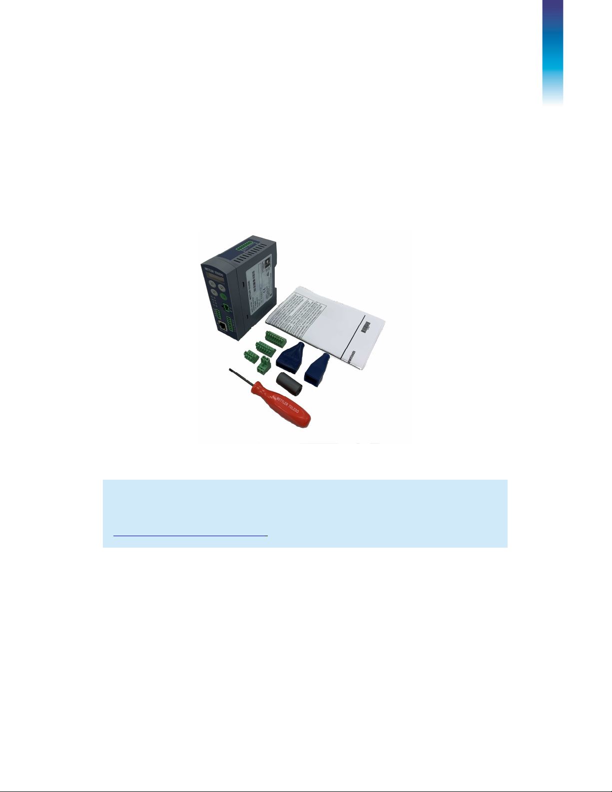
1.1. Inspection and Contents Checklist
Verify the contents and inspect the package immediately upon delivery.
The package should include:
•
•
•
ACT100 transmitter
Safety warnings in multiple languages
Parts for installation, including ferrite, connectors, load cell and Analog
Output connector protection sleeves, etc.
Figure 1-1: ACT100 Packing Materials
NOTICE
All relevant documentation, software, fieldbus files and sample code are available at
www.mt.com/ind-act100-downloads
.
30303895 | 00 | 08/2019
METTLER TOLEDO
ACT350 Transmitter User's Guide 6
Page 11
Introduction
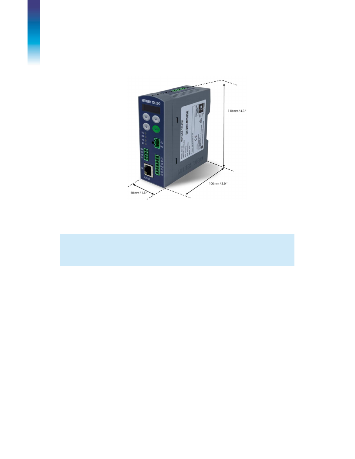
1.2. Physical Dimensions
NOTICE
ACT100 enclosure is shown in Figure 1-2.
Figure 1-2: ACT100 Dimensions
2D and 3D
drawings available at
www.mt.com/ind-ACT100-downloads.
30303895 | 00 | 08/2019
METTLER TOLEDO
ACT350 Transmitter User's Guide 7
Page 12
Operation
2 Operation
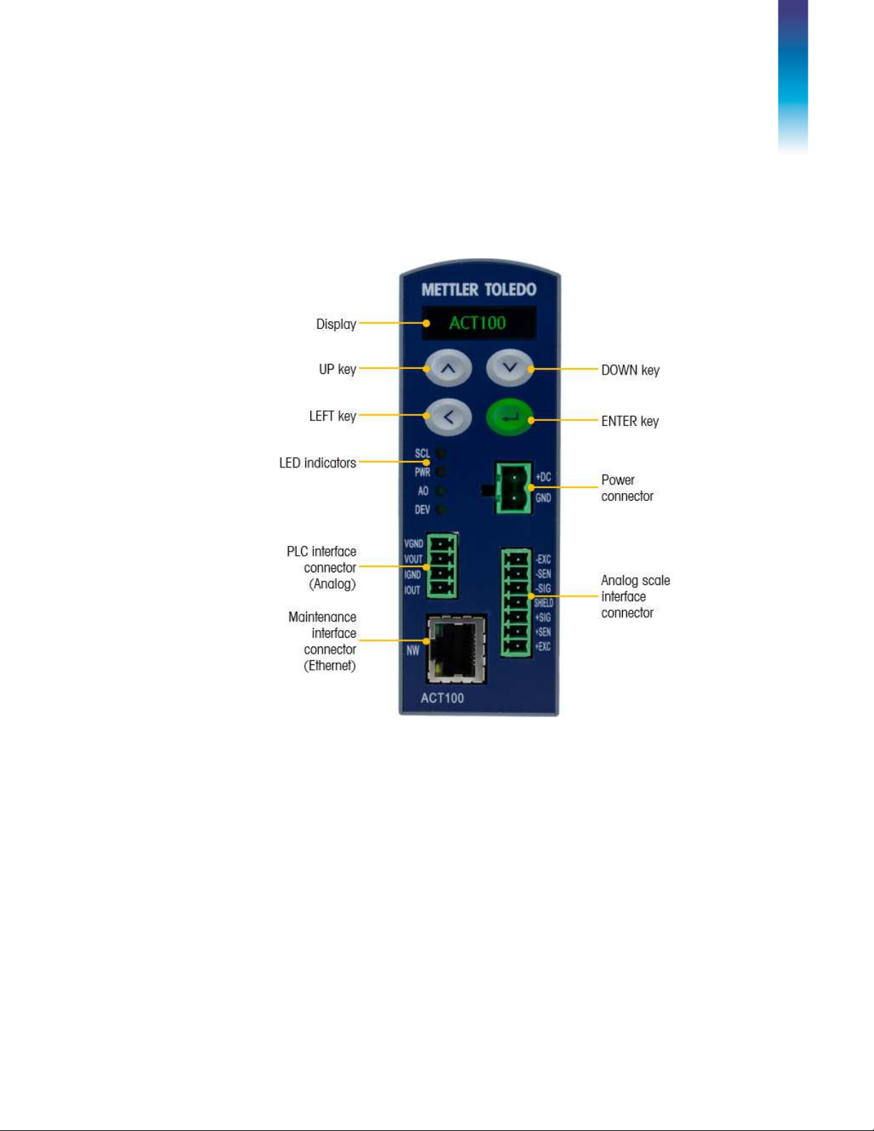
2.1. Front Panel
An example of the ACT100 front panel is shown in Figure 2-1
Figure 2-1: ACT100 Front Panel Layout
2.1.1.
30303895 | 00 | 08/2019
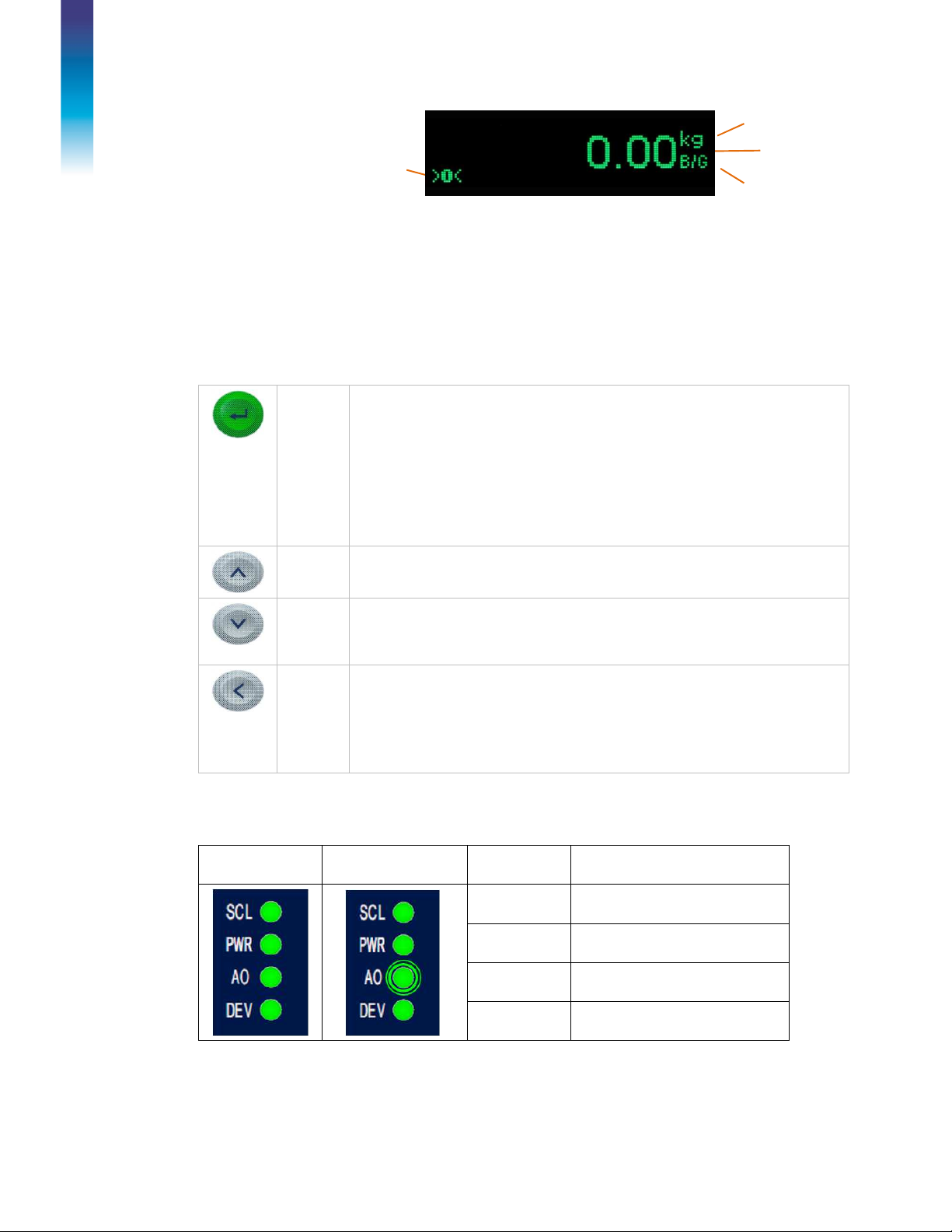
Display Layout
The ACT100 transmitter has an organic LED (OLED) display, 128 x 32 dot
matrix graphic type display. The display is reserved for scale weight, units,
Net/Gross indicator and error messages.
Additional information provided includes:
Weight unit ( Ib, kg, g )
Motion / no-motion condition
Center of zero
Gross or net mode
METTLER TOLEDO
ACT350 Transmitter User's Guide 8
Page 13
Operation
Press the ENTER key for 3 seconds to access the device menu. Press the
Press the UP key to scroll within the device menu and sub
-
menus. The UP
SCL Scales status: ON okay,
DEV Device Status: ON okay;
Center of
Zero
Unit of
measure
indication
Weight display
Figure 2-2 Display in Weighing Mode
2.2. Front Panel Keys
Four dedicated function keys are located on the front panel to support
manual setup configuration. These provide the interface to navigate the setup
menu hierarchy and data entry, as well as make setup selections within data
entry and drop down boxes.
Gross mode
ENTER
DOWN
ENTER key to make a selection from the device menu and sub-menus.
When in a data entry field, press the ENTER key to accept the numeric value
entered.
When the display is in weighing mode, briefly press the ENTER key to
execute the zero operation if the scale weight is within the Pushbutton zero
range specified in the webserver.
UP
key is also used for incrementing numerals in the numeric data entry field.
Press the DOWN key to scroll within the device menu and sub-menus. The
DOWN key is also used for decrementing numerals in the numeric data
entry field.
Press the LEFT key to navigate up one step on the device menu tree. The
LEFT
LEFT key is also used to scroll to the numeral to the left in a data entry field.
With the left most numeric character highlighted, the next key press will
wrap around to the right most numeral.
2.3. LEDs Status
Normal Work Analog Output Error
(Example)
30303895 | 00 | 08/2019
METTLER TOLEDO
ACT350 Transmitter User's Guide 9
LED
flashing indicates scale error
PWR Power status: ON okay, OFF
error
AO Analog Output: ON okay,
flashing out of range
flashing contact service
STATUS
Page 14
Operation
2.4. ACT100 Device Main Menu
From the front panel, press and hold the ENTER key for 3 seconds to access
the device menu. The display will change from showing the normal weight
display to showing the Information Recall icon. Press the UP or
DOWN keys on the front panel to display icons for the various functions
listed in .
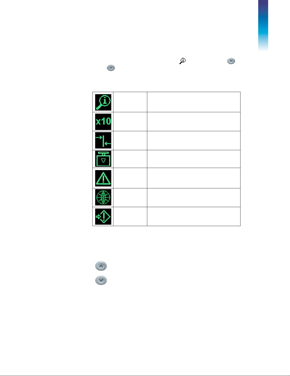
Table 2-1: Device Menu Icons
Information
Recall
Resolution
Comparators
Calibration
Error Message
Language
Setup
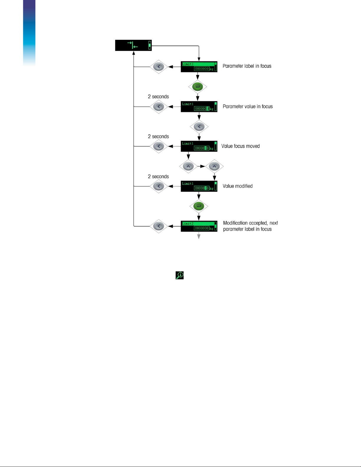
Once focus is in a value field, repeated presses of the UP, DOWN or LEFT keys will
cycle back to the beginning, so if the LEFT key is pressed when focus is in the leftmost position, focus returns to the right-most position. In the case of the UP and
DOWN keys, the highlighted value will cycle through numerical values and the
decimal point as follows:
Selects between English and Chinese
Recall mode for most transmitter information
fields.
Temporarily expands weight display resolution
for diagnostic purposes
Access to the limit value for all currently
enabled comparators.
Access to calibration menu including zero and
span adjustment (in non-approved mode
only).
Access to list of current error messages
Access to all setup parameters for the
transmitter.
0 > 1 > 2 > 3 > 4 > 5 > 6 > 7 > 8 > 9 > . > 0 > 1 >
…
0 > . > 9 > 8 > 7 > 6 > 5 > 4 > 3 > 2 > 1 > 0 > . >
…
After accepting the value by pressing ENTER and the focus has moved to the parameter
description, press the LEFT key to exit to the next higher level of the menu.
Pressing the LEFT multiple times will exit the device menu.
Figure 2-3 shows an example of how to access and modify the value of a parameter.
The currently selected item (in focus) is indicated by reverse video.
30303895 | 00 | 08/2019
METTLER TOLEDO
ACT350 Transmitter User's Guide 10
Page 15
Operation
Figure 2-3: Numerical Data Entry Example
2.4.1.
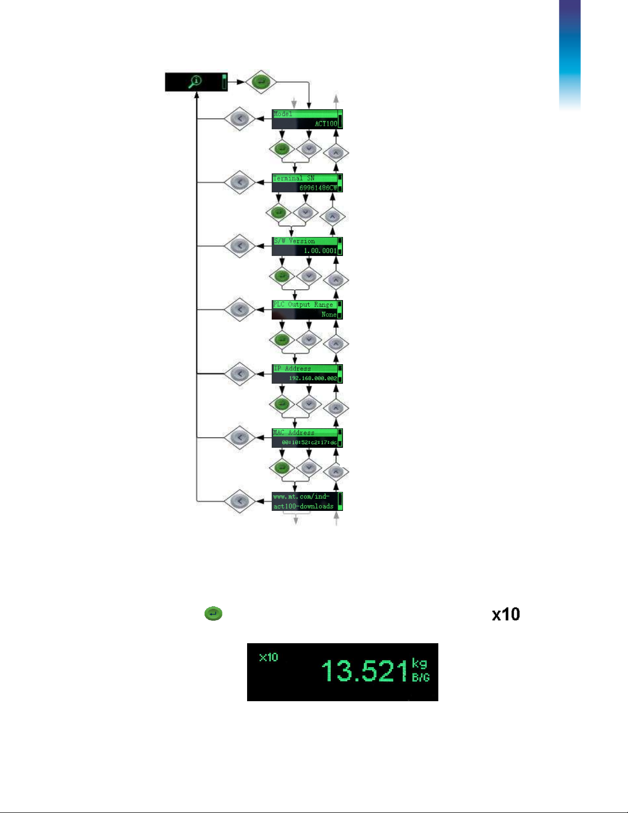
Once the Information Recall icon appears, press the ENTER key to recall specific
information about the transmitter. Figure 2-4 shows the elements of the Information
Recall menu in the sequence in which they occur. Note that some items may not
appear, depending on the configuration of the transmitter.
Pressing the LEFT key multiple times will exit the device menu.
Information Recall
30303895 | 00 | 08/2019
METTLER TOLEDO
ACT350 Transmitter User's Guide 11
Page 16
Operation
The model number of the
Indicates
Analog Output
type
Shows the device IP
address
Shows the MAC address assigned
transmitter (ACT100) is shown.
Serial number of the transmitter
Displays information about the
standard firmware version
2.4.2.
to the network
Provides network address for
online resources
Figure 2-4: Information Recall Menu
x10 Resolution
This function expands the weight display resolution by 10 so that a finer
weight increment can be seen. It can be enabled by pressing the ENTER key
when the transmitter’s device menu has been accessed and the
icon is displayed on screen:
Figure 2-5: x10 Indication
30303895 | 00 | 08/2019
METTLER TOLEDO
ACT350 Transmitter User's Guide 12
Page 17

Operation
NOTICE
This function is intended for
the x10 expanded mode for normal operation.
diagnostic purposes only
. The transmitter should not be used in
2.4.3.
Comparators
The device supports a total of three comparators. One, two or all three
comparators may be used. The limit of each comparator may be modified by
accessing the Comparator menu in the setup menu. Comparator values are
limited to 7 digits.
2.4.3.1. Setting Comparators
Access the Comparator menu by pressing the ENTER key when the
transmitter’s device menu is visible and the icon is displayed on the
device.
The ACT100 only supports a logical comparison of “>=”, greater than or equal
to, for each comparator. For example, if the limit is set to “24.00” kg, the
output configured to use this comparator will be set to true only if the live
weight is greater than or equal to 24.00 kg. Please note that inputs and
outputs can be configured using the webserver.
The operator of range and other comparisons are NOT supported by the
ACT100.
30303895 | 00 | 08/2019
METTLER TOLEDO
ACT350 Transmitter User's Guide 13
Page 18

Operation
2.4.4.
Calibration
Calibration is the process of adjusting the display of the transmitter so that
when the scale is empty, the display shows zero gross weight. With a
specific amount of weight on the scale, it also shows an accurate weight
value.
The ACT100 transmitter calibration menu enables entry of an adjustment
value, selection of linearity adjustment (
point), traditional zero calibration and three different types of span
calibration:
•
Traditional span calibration – This uses test weights.
•
Step adjust calibration - Using a build-up or substitution method of
calibration, this method is used for large vessels where only a portion of
the required test weights can be placed on the scale.
[default], three, four or five
none
•
CalFree calibration
manually, the transmitter will automatically calculate the span; no test
weights are required.
– Once certain load cell criteria have been entered
30303895 | 00 | 08/2019
METTLER TOLEDO
ACT350 Transmitter User's Guide 14
Page 19

Operation
2.4.4.1. Setting Calibration
Access to the Calibration menu using the device's front panel is accomplished
by pressing the ENTER key when the icon is displayed on the device.
The Calibration menu also can be accessed using the webserver.
2.4.4.2. Setting Geo Code
The Geo code, which sets the appropriate adjustment value for the current
geographical location, is selected here. Geo codes are numbered 0–31. See
Figure 2-6 for more information on the Geo code setting using the transmitter’s
front panel buttons, and refer to Chapter 5 to find the appropriate Geo Code
for the installation location.
30303895 | 00 | 08/2019
Figure 2-6: Calibration Menu – Overview
METTLER TOLEDO
ACT350 Transmitter User's Guide 15
Page 20
Operation
3
Zero, midpoint and highpoint
2.4.4.3. Setting Linearity
To set the Linearity Adjustment value, see Figure 2-6: Calibration Menu –
Overview. Choose the number of linearity points from the selection box.
Options are
Points are distributed as follows:
None
None
4
5
[default], 3 point, 4 point, 5 point.
Linearity is disabled
Zero, lowpoint, midpoint and
highpoint
Zero, lowpoint, midpoint, midhighpoint, highpoint
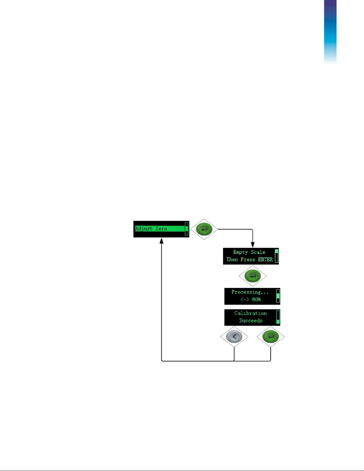
2.4.4.4. Zero Calibration and Under Zero Blanking
Scale zero is set simply by emptying the scale and running the “Set Zero”
calibration routine, as shown in Figure 2-7.
30303895 | 00 | 08/2019
Figure 2-7: Zero Calibration
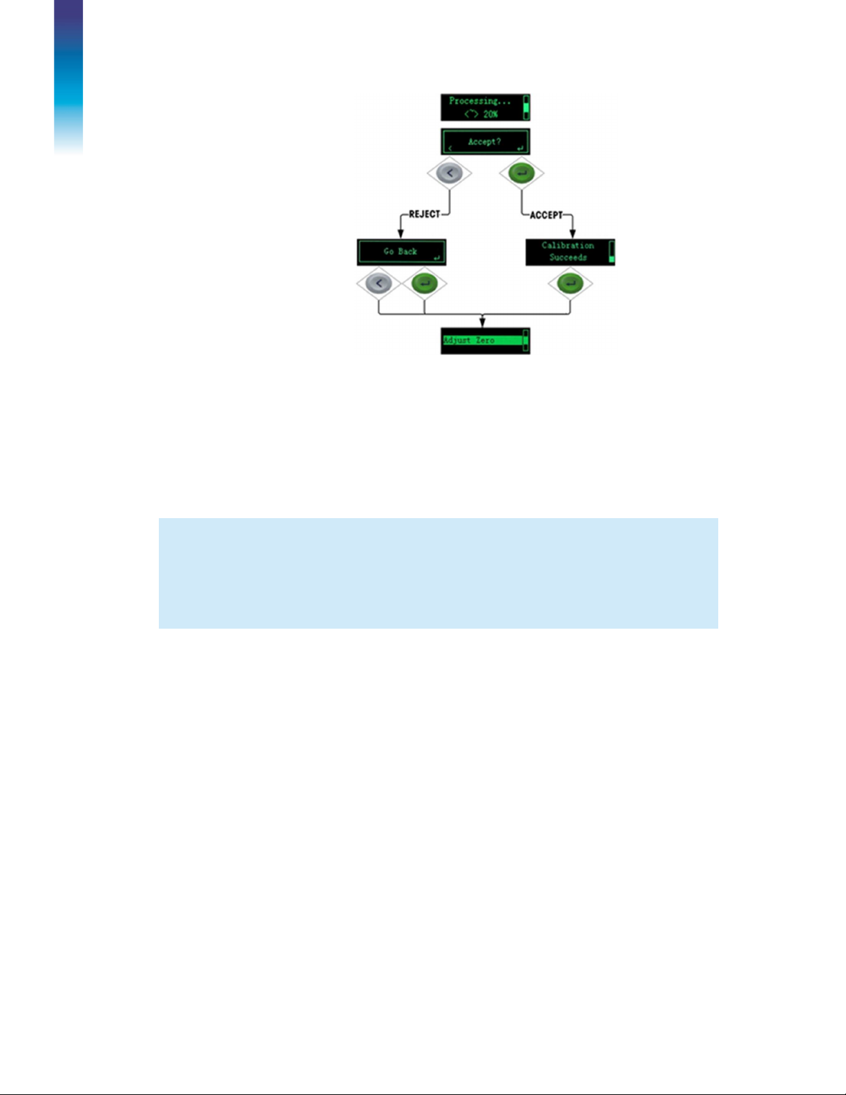
If the transmitter detects scale motion during the calibration process, it will
retry the start of calibration several times and then proceed, displaying a
motion indication. In this case, when calibration is complete, the transmitter
will present two options – accept or reject the value.
METTLER TOLEDO
ACT350 Transmitter User's Guide 16
Page 21
Operation
NOTICE
Figure 2-8: Zero Calibration with Motion
Blanking of the display is used to indicate an under-zero condition when the
weight on the scale falls below the current zero reference. Set the under zero
blanking for the number of divisions (d) that the transmitter is permitted to
go under zero before blanking.
A setting value of 0-98 blanks the display at the specified number of divisions below gross
zero. A value of 99 makes the transmitter blanks at 50% of the capacity value in the negative
direction.
2.4.4.5. Span Calibration
The scale’s span calibration can be determined either with or without a
linearity adjustment. With linearity disabled, a single reference point is used
to calibrate the scale. This is the normal method of span calibration. With
linearity enabled, the transmitter is configured with up to three-point linearity
– low, mid and high.
The low point is set during zero calibration, and the mid and high points are
set during this procedure.
30303895 | 00 | 08/2019
METTLER TOLEDO
ACT350 Transmitter User's Guide 17
Page 22

Operation
Figure 2-9: Span Calibration
If linearity is enabled, additional mid-range weight reference points are added
to the adjustment procedure. Linearity can be enabled or disabled in the
Calibration branch of the device menu. Refer to ACT100 Device Main Menu
section for the method used to modify numerical values.
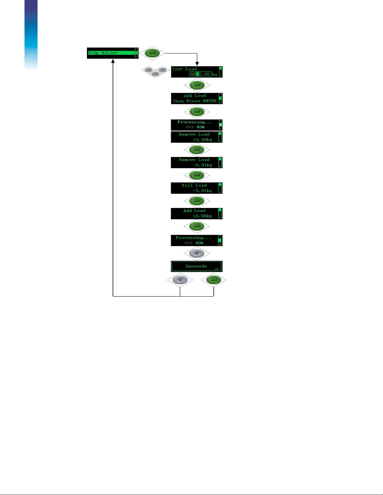
2.4.4.6. Step Adjust
Step adjustment is an iterative process in which a build-up or material
substitution method of calibration is used to calibrate the span. Each step
calibrates a portion of the full span.
This method is typically used with large vessels where only a portion of the
required calibration test weights can be placed on the scale at one time. Figure
2-10 shows the logic of the procedure using a simple, two-step example.
When sufficient steps have been calibrated, pressing the LEFT button returns
the view to the calibration menu.
30303895 | 00 | 08/2019
METTLER TOLEDO
ACT350 Transmitter User's Guide 18
Page 23
Operation
First, a test load is defined by entering its
weight.
Confirm the value entry by pressing ENTER.
The ACT100 prompts for the addition of the test
load.
Press ENTER to start the first step,
The ACT100 indicates its progress.
Once the first step is calibrated, the ACT100 sets
a temporary zero point, and prompts for the
removal of the test load. A live weight display
indicates that the scale has been cleared.
Press ENTER to confirm the scale is empty.
The ACT100 will prompt to add the test load
again.
The live weight indicates that the test load is on
the scale.
Press ENTER to start the second step.
The ACT100 indicates its progress.
Press LEFT to complete calibration and exit the
procedure.
The ACT100 indicates that the calibration has
succeeded.
Press either LEFT or ENTER to return to the
calibration menu.
Figure 2-10: Step Adjustment
30303895 | 00 | 08/2019
METTLER TOLEDO
ACT350 Transmitter User's Guide 19
Page 24

Operation
2.4.4.7. CalFree™
NOTICE
CalFree allows the scale to be calibrated without the use of test weights. The
total load cell capacity, unit and output in mV/V must be entered. The system
then calculates correct calibration for the scale. Figure 2-11 provides a visual
representation of the CalFree calibration procedure.
Notes on Load Cell Capacity and Rated Cell Output
•
For load cell capacity, enter the sum of all load cell capacities. For
example, for three 50t load cells, enter 150,000 kg.
•
For systems with passive dummy load cells, enter the value as if all legs
have live load cells. For example, for a system with two 50t live load cells
and two passive supports, enter 200,000.
•
For Rated Cell Output, enter the sensitivity of each live load cell in mV/V –
for example, 2.0000. For multiple load cells, enter the average sensitivity of
all cells.
The ACT100 transmitter allows calibration of the scale without using test
weights. This is based on manual entry of capacity and performance data
from the load cell or load cell platform. This method of calibration can be
used for initial check-out and testing of systems or when a large structure is
used as the weighing vessel and it is not possible to apply test weights to the
structure. METTLER TOLEDO highly recommends that test weights be used
whenever possible, as this provides the most accurate method of calibration.
The Rated Cell Output and Cell Capacity values cannot be zero, and are
limited to 7 digits.
Scale calibration using CalFree™ will not be accurate when using zener diode barriers (such
as Mettler Toledo ISB05 and ISB05x) between the transmitter and the scale. Do not use
CalFree™ when barriers are installed.
30303895 | 00 | 08/2019
METTLER TOLEDO
ACT350 Transmitter User's Guide 20
Page 25

Operation
Figure 2-11: CalFree
30303895 | 00 | 08/2019
METTLER TOLEDO
ACT350 Transmitter User's Guide 21
Page 26

Operation
2.4.5.
Language
2.4.6.
2.4.7.
The ACT100 supports a device menu in
[default] and in Chinese.
English
Parameters Setup
The last icon displayed in the device menu from the front panel is Setup ,
where many of the transmitter’s programming parameters can be viewed
and modified. It is not intended that operators enter the setup mode after a
weighing system is installed and is operational. It should not be necessary
for an operator to access setup.
Password Security
Note that a security password can be enabled in setup from the Web-based
Configuration Tool. When a password is set, it must be entered to access
setup. This protects the setup parameters from inadvertent changes. The
default password is "000000".
Figure 2-12: Password Entry Screen
2.4.8. Reset Configuration and Master Reset
2.4.8.1. Reset Configuration
To reset all configured items except calibration data:
1.
Remove power from the transmitter.
2.
Locate the DIP switches, accessible from the underside of the housing.
3.
Set both DIP switches, 1 and 2, to ON (up, in ), and restore power to
the transmitter.
4.
Set both DIP switches to OFF.
Figure 2-13: DIP Switches
30303895 | 00 | 08/2019
METTLER TOLEDO
ACT350 Transmitter User's Guide 22
Page 27

Operation
2.4.8.2. Master Reset
A master reset restores all settings to their factory default values:
1.
2.
3.
4.
Remove power from the transmitter.
Set switch 2 to its ON position and restore power to the transmitter.
The ACT100 will prompt for confirmation.
Figure 2-14: Master Reset Confirmation
Press ENTER on the front panel to perform the master reset.
Set Switch 2 to OFF.
2.2. ACT100 Basic Operation Functions
2.2.1.
2.2.1.1. Green ENTER Button
2.2.1.2. Power Up
Zero
The Zero function is used to set or reset the initial zero reference point of the
transmitter. There are two types of zero setting modes:
The zero function can be accomplished by a short press of the green ENTER
scale function key. The Zero range selections include Disabled, 2%
[default] or 20% plus or minus from the calibrated zero point. A change to
the default setting is done via the webserver. If the current scale weight is
outside the zero range when a pushbutton zero is commanded, the transmitter
will display a message:
Figure 2-15: ENTER button Zero Failure Message
The Power Up mode setting determines if at power up, the transmitter will
restart with the most recent zero reference point it had before power down or
if it will reset to the calibrated zero reference.
The selections include
30303895 | 00 | 08/2019
METTLER TOLEDO
[default] and
Reset
ACT350 Transmitter User's Guide 23
Restart
.
Page 28

Operation
2.2.1.2.1. Reset
With the setting on Reset, the last zero calibration value will be used as the
zero reference point. The Power Up Zero capture range selections include
Disabled
the Power Up Zero is applied only when the weight reading on the scale is
within the selected range around the originally calibrated zero reference. For
example, if the range setting for Power Up Zero is set at +/- 2%, Power Up
Zero will only occur when the weight reading on the scale is within +/- 2%
of scale capacity above the original calibrated zero reference. If the weight
on the scale is outside of the zero range, the display will indicate
the weight is adjusted to within this range and zero is captured.
[default], 2% or 10% plus or minus. If the range setting is enabled,
EEE
2.2.1.2.2. Restart
A setting of Restart enables the transmitter to reuse the most recent zero
reference weight after a power cycle so it returns to the same, previouslydisplayed gross weight value. The Power Up Zero setting is configured using
the webserver.
until
2.2.2.
Tare
The tare value is subtracted from the gross weight measurement, providing
the computation of the net weight (material without the container). The tare
function can also be used to track the net amount of material being added to
or removed from a vessel or container. In the second case, the weight of the
material inside is included with the tare weight of the container and the
display reflects the net amount being added to or removed from the vessel.
Tare is captured by digital input. Tare is cleared by digital input.
30303895 | 00 | 08/2019
METTLER TOLEDO
ACT350 Transmitter User's Guide 24
Page 29

Operation
Weighing
Normal:
Should only be used for non
-
automatic, human
-
Limit
1-20 Hz:
Marks the point at which the filtering process
Environment
Very Stable, Stable, Standard, Unstable, Very Unstable:
Sets the level of attenuation applied to the signal above the
Source
Selects either
Display Weight
or
Gross Weight
as the
Analog
Zero
Sets the weight value that corresponds to the low end of
2.2.3.
Filter
In many weighing applications, vibration can introduce error into your system
or cause delays in the transfer of weight to your automation device. It is
always recommended to first attempt to mechanically isolate your scale from
the surroundings. When this cannot adequately be done, use the electronic
filtering inside the ACT100. The Filter section offers three settings: Weighing
Mode, Limit Frequency and Environment.
Mode
Frequency
powered weighing. Gives the most stable response that is
required for "legal for trade" weighing. Not recommended
with a process controlled by an automation device.
Dynamic:
automation device such as a PLC.
Trigger Weigh:
instead of Trigger Weigh
begins to affect the disturbance. Disturbances above the limit
frequency will have filtering applied. Recommendation is to
start at 20 Hz and reduce the frequency only after adjusting
the environment setting. The lower the frequency, the better
the disturbance rejection, but it will extend the settling time.
Intended setting when process is controlled by
Recommended to use Dynamic mode filter
2.2.4.
limit frequency. A very stable environment will have the least
attenuation applied to the signal and a very unstable
environment will have the strongest attenuation. It is
recommended to adjust this value first when changing filter
settings. Start with "very stable" and work your way down.
Analog Output
The Analog Output section offers five settings
source of the analog output
Output Type
Value
Analog Span
Value
Sets the type of analog output signal provided. Available
ranges are
24mA
the selected Output Range. Weight values less than or
equal to the Zero Value causes the device to output the
lowest value of the Output Range.
Sets the weight value that corresponds to the high end of
the selected Output Range. Weight values greater than or
None, 0-5V, 0-10V, 4-20mA, 0-20mA, 0-
.
30303895 | 00 | 08/2019
METTLER TOLEDO
ACT350 Transmitter User's Guide 25
Page 30

Operation
equal to the Full Scale Value
causes the device to output
the highest value of the Output Range.
Calibrate
Output
Assumed below values set to ACT100
Source: Gross Weight
Output Type: 4~20mA
Analog Zero Value: 0 kg
Analog Span Value: 1000 kg
This means ACT100 will output 4mA when scale is empty and 20mA when
1000 kg load on scale or in tank. If the load on scale exceeds 1000kg, the
analog signal value will change from 20mA to 24mA as a warning message
to user control system that the analog output is over range. Figure 2-16
shows the relationship between analog output signal and load on scale.
Allows for a minor adjustment to be made to the analog
output signal. First, an adjustment to the zero value
signal will be made. Second, an adjustment to the full
scale signal will be made. Adjustment should be
completed with either PLC or multimeter connected to
analog output of ACT100. Adjustment is completed by
using the up or down buttons on the ACT100. A short
press (fine adjust) of the button makes an adjustment in
step size of 10. A long press (coarse adjust) of the
button makes an adjustment in step size of 200.
30303895 | 00 | 08/2019
2.2.5.
Figure 2-16: Analog Output Example
Error Message
With the Errors icon in view, press the ENTER key to access a listing of
current error messages.
METTLER TOLEDO
ACT350 Transmitter User's Guide 26
Page 31

Operation
009 “Board info. Err”
Hardware production
Cycle power; call MT
010 “Calib. Block err”
Calibration block data
Perform master reset
011 “Scale block err”
Scale block data error
Perform master reset
022 “Tare failed
Tare failed due to scale
Wait scale to be stable
029 “Tare failed Zero
Tare failed due
to
Capture the Power
-
up Zero
030 “Tare Failed, over
Tare failed due to scale
Unload weight on scale
Table 2-2: ACT100 Faults
Error
value
012 “Term. Block err” Transmitter block data
013 “APP. Block err” Application block data
014 “COM. Block err” Communication block
015 “Maint. Block err” Statistics block data
016 “Analog system
018 “Zero failed
ACT100 Display Description Action
information error
error; block data is lost
error
error
data error
error
Lost analog signal;
A/D fail”
Motion”
abnormal functioning
of scale
Zero failed due to scale
is in motion
Service if issue persists
Re-calibrate
Perform setup for scale
block
Perform master reset
Perform setup for
transmitter block
Perform master reset
Perform setup for
application block
Perform master reset
Perform setup for
communication block
Perform master reset
Perform setup for
maintenance block
Call MT Service
Wait scale to be stable
019 “Zero failed Net
mode”
020 “Zero failed/Out of
range”
021 “Zero failed Zero
disabled”
Motion”
not captured”
capacity”
031 "Tare failed
Negative value"
Zero failed due to scale
is in Net mode
Weight out of zero
range
Zero attempted when
function disabled in
Setup menu
is in motion
Power-up Zero is not
captured
being over capacity
Tare failed due to
current gross weight is
negative
Attempt to Zero after Clear
operation is performed
Unload scale and perform
Zero again
Enable Zero function in
Setup menu
or disable Power-up Zero
before Tare
until overcapacity is
cleared and perform Tare
again
Adjust the weight on scale
to make gross weight
positive
30303895 | 00 | 08/2019
METTLER TOLEDO
ACT350 Transmitter User's Guide 27
Page 32

Operation
035 "Analog saturation"
A/D converter in
Check the input
036 "Factory zero not
done"
overload
Factory Zero calibration
not performed
signal(should be between
0mV and 20mV)or call MT
Service
Call MT Service
037 "Factory span not
done"
050 "LC Connection
Error"
Factory Span
calibration not
performed
Lost connection
between ACT100 and
LC
Call MT Service
Check the LC and
connection cables
30303895 | 00 | 08/2019
METTLER TOLEDO
ACT350 Transmitter User's Guide 28
Page 33

Installation
3 Installation
3.1. Mechanical Installation
The ACT100 mounts to a standard DIN rail. DIN mount includes an
integral transmitter grounding system, visible in
Grounding
Figure 3-1
.
Upper mounting tabs
Sliding latch
Figure 3-1: DIN-Mount Latch
To mount the ACT100 on a rail, open the latch by pulling down, then position
the transmitter so that its upper tabs rest on the DIN rail.
Use a screwdriver to close the latch and secure the transmitter in position.
Figure 3-2: Latch Closure
30303895 | 00 | 08/2019
METTLER TOLEDO
ACT350 Transmitter User's Guide 29
Page 34

Installation
To remove the ACT100, simply put the blade of a screwdriver in the latch
1 Power connector (12
- 30 VDC)
2 Analog Output (4
-
20mA, 0
-
10V,
0-5V, 0
-
20mA, 0
-
24mA)
NOTICE
and press it downward.
In order to ensure proper dissipation of heat from the transmitter’s PCBs, and to avoid damage
to the equipment,
the ACT100 must be mounted vertically
, on a horizontal din rail.
3.2. Electrical Installation
Figure 3-3 indicates ACT100 connections and their functions.
30303895 | 00 | 08/2019
Connections:
METTLER TOLEDO
Figure 3-3: ACT100
ACT350 Transmitter User's Guide 30
Page 35

Installation
3 Analog scale interface
(Number of load cells: up to
4x 350Ω
or
Permissible input voltage
0~24 VDC 5
~30 VDC
NOT
ICE
10x 1000Ω; 1-4 mV/V; Number of scale: 1; Number of scale
ranges: 1; Load cell excitation voltage: 5 VDC; 6 wire
connection)
4 Ethernet connection
The special automatic grounding system at the back of the unit is present to ensure that the unit
is grounded to the DIN rail. See Figure 3-1
3.2.1. Digital Inputs and Outputs Connection
Three inputs and two outputs are located on the top of the ACT100. Table
3-1 contains the specifications for the digital inputs and outputs.
Figure 3-4: ACT100, Top View (DIO model shown)
30303895 | 00 | 08/2019
Table 3-1: Digital Inputs and Outputs Specification
Input Output
Logical Low-level
Logical High-level
Input resistance
METTLER TOLEDO
0 ~ 3 VDC
10 ~ 24 VDC
>3Kῼ
ACT350 Transmitter User's Guide 31
Page 36

Installation
Max.current of one output
Accumulated current of
Power source to
IN
-
Polarity Value
+True(Default) or
–
True
None; Center of Zero;
NOTICE
<150mA
all outputs
Support Sinking
Support Sourcing
Default function
Available Functionality
Example:
operation, "Polarity" can be set as "+ True" and "Assignment" as "Zero". Refer to
Figure 3-5
Using a rising-edge input signal to trigger the ACT100 to perform a Zero
:
GND connected to IN-
None; Clear Tare; Tare;
Zero; Abort SetPoint;
Start/Resume SetPoint
<300mA
GND connected to OUT-
COM
COM
None None
Power source to OUT-COM
Comparator 1-3; Fault;
Motion; NET; Over Capacity;
Under Zero; Fast Feed; Fine
Feed; Analog Output Over
Range; Analog Output
COM
Under Range, LC
Connection Error
Figure 3-5: A Rising-edge Trigger Signal on Input
Using a falling-edge input signal to trigger ACT100 to perform a Tare operation,
"Polarity" can be set as "- True" and "Assignment" as "Tare". Refer to Figure 3-6.
Figure 3-6: A Falling-edge Trigger Signal on Input
Do not use input voltage between 3 – 10 VDC. Unstable input signal will result. See figure 36 and 3-7 for proper operation
30303895 | 00 | 08/2019
METTLER TOLEDO
ACT350 Transmitter User's Guide 32
Page 37

Installation
Digital inputs and Outputs electrical connection instructions are shown below.
(From Figure 3-7 to Figure 3-10)
1
IN1
IN2
IN3
------
IN COM
8
OUT1
OUT2
OUT COM
PLC or Other
Discrete Output
Voltage Source
+ Voltage Source
PLC or Other
Discrete Output
Device
Voltage Source
Common
+ Voltage Source
COM
OUT1
Device
OUT2
OUT3
Figure 3-7: Sinking Input, Sourcing Output
Common
COM
OUT1
OUT2
OUT3
+ Voltage Source
Voltage Source
Common
LOAD
SUPP
LOAD
SUPP
1
IN1
IN2
IN3
------
IN COM
8
OUT1
OUT2
OUT COM
Voltage Source
Common
+ Voltage Source
LOAD
SUPP
LOAD
SUPP
Figure 3-8: Sinking Input, Sinking Output
30303895 | 00 | 08/2019
METTLER TOLEDO
ACT350 Transmitter User's Guide 33
Page 38

Installation
+ Voltage Source
1
IN1
IN2
IN3
------
IN COM
8
OUT1
OUT2
OUT COM
+ Voltage Source
Voltage Source
PLC or Other
Discrete Output
Device
+ Voltage Source
Common
COM
OUT1
OUT2
OUT3
Figure 3-9: Sourcing Input, Sourcing Output
1
IN1
IN2
IN3
-----OUT1
IN COM
OUT2
Voltage Source
LOAD
SUPP
LOAD
SUPP
8
OUT COM
Voltage Source
Common
Common
Voltage Source
PLC or Other
Discrete Output
Device
Common
COM
OUT1
OUT2
OUT3
+ Voltage Source
LOAD
SUPP
LOAD
SUPP
Figure 3-10: Sourcing Input, Sinking Output
30303895 | 00 | 08/2019
METTLER TOLEDO
ACT350 Transmitter User's Guide 34
Page 39

Installation
3.2.2. Analog Output Connection
PLC Analog Input
Interface
1 4
IOUT
IGND
VOUT
VGND
-
+
-
+
Figure 3-11: Analog Output Connection
For ESD protection, cabling for the analog output must include a silicone
protection sleeve, included with the transmitter.
Figure 3-12: Silicone Sleeve Installed on Analog Output Cable
3.2.3. Analog Load Cell Connection
For ESD protection, cabling for the analog load cell must include a ferrite
and a silicone protection sleeve, included with the transmitter.
Install the ferrite by passing it through the ferrite and wrapping it around
once, as indicated here.
30303895 | 00 | 08/2019
METTLER TOLEDO
ACT350 Transmitter User's Guide 35
Page 40

Installation
NOTICE
Silicone sleeve
Ferrite
Analog load cell connector
Figure 3-13: Ferrite Installed on Analog Load Cell Cable
To accommodate the ferrite, it may be necessary to cut the silicone sleeve to size.
Table 3-2 Recommended Maximum Cable Lengths
TSR (Ohms)
350 234/800 610/2000 1219/400
87
(4 -350 Ω cells)
24 Gauge
(meters/feet)
60/200 182/600 304/1000
3.2.4. PLC Connection
To connect ACT100 with a PLC, use the analog output port shown on Figure
3-3.
Figure 3-14 presents a connection diagram of a weighing system using
an ACT100.
20 Gauge
(meters/feet)
16 Gauge
(meters/feet)
30303895 | 00 | 08/2019
Figure 3-14: ACT100 Based Weighing System
METTLER TOLEDO
ACT350 Transmitter User's Guide 36
Page 41

Installation
3.3.
3.3. DIP Switches
Two DIP switches, 1 and 2, are accessible from the underside of the
ACT100’s housing. Table 3-3 summarizes their functions.
ACT100 DIP Switches Legal for
Table 3-3: DIP Switch Functions
Reset
Trade
Switch 1 Switch 2 Function
OFF OFF Normal operation
ON OFF Protection mode for
important parameters,
e.g. calibration values
OFF ON Master reset of all data
during transmitter powerup
ON ON Reset of all
calibration data during
transmitter power-up
except
3.4. Power Supply
The ACT100 transmitter is powered only by external DC input (12V to 30V).
Table 3-4: ACT100 Power Consumption
1x 350Ω
Supply Voltage
12 VDC 265 3.18 290 3.48
24 VDC 160 3.84 170 4.08
30 VDC 135 4.05 145 4.35
4x 350Ω
Loadcell
Current
(mA)
Power
(W)
Loadcell
Current
(mA)
Power
(W)
30303895 | 00 | 08/2019
METTLER TOLEDO
ACT350 Transmitter User's Guide 37
Page 42

Configuration
Webserver
Configuration
NOTICE
4 Webserver Configuration and
Maintenance Tool
4.1. Webserver
Webserver supports the following functions:
•
Configuring of the ACT100 Transmitter via web browser, such as IE,
Chrome and Safari;
•
Accessing diagnostic and maintenance information for service
purposes;
Figure 4-1 Webserver Splash Screen
By inputting the IP address of ACT100 Transmitter in the web browser,
the startup screen of webserver will be displayed.
4.1.1. Webserver Setup
4.1.1.1. PC setup
Make sure the PC and ACT100 Transmitter are in the same local network.
The typical PC's configuration:
IP address: 192.168.0.X (X = 0 ~ 254, exclude 2), Subnet Mask:
255.255.255.0, Default Gateway: can be left blank
30303895 | 00 | 08/2019
METTLER TOLEDO
ACT350 Transmitter User's Guide 38
Page 43

Webserver Configuration
NOTICE
Figure 4-2 Local Area Connection Setting
The default setting of the ACT100 Transmitter is as follows:
IP address: 192.168.0.2, Subnet Mask: 255.255.255.0, Gateway: 192.168.0.1
4.1.1.2. IE setup
Internet Option -> LAN setting -> Automatically detect settings should
be unchecked.
.
30303895 | 00 | 08/2019
Figure 4-3 IE setting
METTLER TOLEDO
ACT350 Transmitter User's Guide 39
Page 44

Configuration
Webserver
Configuration
Display Language
This sets the language to be used on
4.2. Elements of Webserver
4.2.1. Device Information
The device information page displays basic information about the
ACT100. Transmitter information includes the serial number of the unit
and the current software version. The service Ethernet configuration
includes the IP address of the ACT100, subnet mask, MAC address
and default gateway. None of this information can be edited from this
screen.
Figure 4-4 Device Information
4.2.2. ACT100 Basic Settings
The ACT100 basic settings include three options:
Display Auto Off This sets the amount of inactive time
Pushbuttons This allows the pushbuttons on the
required before the display on the
front of the ACT100 automatically
turns itself off. The options are 1
minute, 10 minutes, 30 minutes, or
this feature can be disabled so the
display does not turn off
automatically.
the ACT100 display. The options are
English or Chinese.
front of the ACT100 to be either
enabled or disabled. If disabled, the
only way to enable the pushbuttons
again is via the webserver.
30303895 | 00 | 08/2019
METTLER TOLEDO
ACT350 Transmitter User's Guide 40
Page 45

Webserver Configuration
Source
Selects either
Display Weight
or
Figure 4-5 ACT100 Basic Settings
4.2.3. Analog Output
4.2.3.1. Analog Output Settings
Gross Weight as the source of the
analog output
Output Type Sets the type of analog output signal
provided. Available ranges are None,
0-5V, 0-10V, 4-20mA, 0-20mA, 024mA.
Analog Zero Value Sets the weight value that
corresponds to the low end of the
selected Output Range. Weight
values less than or equal to the Zero
Value causes the device to output
the lowest value of the Output
Range.
Analog Scale Value Sets the weight value that
corresponds to the high end of the
selected Output Range. Weight
values greater than or equal to the
Full Scale Value causes the device to
output the highest value of the
Output Range.
30303895 | 00 | 08/2019
Figure 4-6 Analog Output Settings
METTLER TOLEDO
ACT350 Transmitter User's Guide 41
Page 46

Configuration
Webserver
Configuration
4.2.3.2. Analog Output Adjustment
Allows for a minor adjustment to be made to the analog output signal.
First, press the “Start” button to initiate an adjustment to the zero value
signal will be made. Second, an adjustment to the full scale signal will
be made. Adjustment should be completed with either a PLC or
multimeter connected to the analog output of ACT100.
Adjustment is completed by using the "+", "++", "-", and "--" buttons
on the webserver screen. Pressing the "+" or "-" (fine adjust) button
makes an adjustment of 10 steps positively or negatively. Pressing the
"++" or "--" (coarse adjust) button makes an adjustment of 200 steps
positively or negatively.
Press “Continue” to proceed in the adjustment process from Zero Value
to Span Value. Press “ESC” to cancel the current adjustment step,
please note the prior step adjustment result has been saved.
Figure 4-7 Analog Output Adjustment
Figure 4-8 Example of Zero Value Adjustment
30303895 | 00 | 08/2019
METTLER TOLEDO
ACT350 Transmitter User's Guide 42
Page 47

Webserver Configuration
4.2.4. Calibration
4.2.4.1. Calibration Setting
Calibration offers two settings that can be changed:
Geo Used to set the Geo code based on
Linearity This is the number of points of
where the ACT100 is located in the
world. The valid range is 0-31. See
Section 5 of this document for more
information on Geo Codes.
linearity to be used in calibration.
Options are 3 point, 4 point, 5 point
or none. Please note that even after
a change to the number of linearity
points is submitted, the user must
execute a "Set Span" or "Step
Calibration" for this change to be
saved.
4.2.4.2. Set Zero
Scale zero is set simply by emptying the scale and pressing the “Start”
button on the Set Zero page.
30303895 | 00 | 08/2019
Figure 4-9 Calibration Setting
Figure 4-10 Press “Start” to Initiate the scale Zero Adjusmtnet
METTLER TOLEDO
ACT350 Transmitter User's Guide 43
Page 48

Configuration
Webserver
Configuration
If zero is successfully captured, a message showing the zero capture
has completed is displayed. The user can navigate away from the
page if they are satisfied with the zero captured or they can begin the
process over again.
If motion occurs during adjustment, a message “Capture zero
completed in dynamic” will be shown as seen in Figure 4-12.
4.2.4.3. Set Span
The scale’s span calibration can be set either with or without a linearity
adjustment. With linearity disabled, a single reference point is used to
calibrate the scale. This is the normal method of span calibration. The
webserver will display the correct number of test load points to be used
in the calibration according to the linearity setting found in the
Calibration Setting menu.
Figure 4-11 A successful Zero Adjustment
Figure 4-12 A Dynamic Zero Adjustment
30303895 | 00 | 08/2019
The process begins by entering the weight value into test load 1 and
loading the scale with the corresponding test weight. Click the start
button to calibrate that load point.
METTLER TOLEDO
ACT350 Transmitter User's Guide 44
Page 49

Webserver Configuration
Figure 4-13 Enter Test Load Value
Repeat this process for the rest of the test loads displayed on the
webserver. When complete, the page will ask whether or not to save
the calibration.
Figure 4-14 A Successful Span Adjustment
If motion occurs during adjustment, a message “Span adjustment
complete in dynamic” will be shown as seen in Figure 4-15.
Figure 4-15 A Dynamic Span Adjustment
4.2.4.4. Step Calibration
Step adjustment is an iterative process in which a build-up or material
substitution method of calibration is used to calibrate the span. Each
step calibrates a portion of the full span.
This method is typically used with large vessels where only a portion
of the required calibration test weights can be placed on the scale at
one time. It starts from inputting the Test Load value in Figure 4-16
and pressing the “start” button.
30303895 | 00 | 08/2019
METTLER TOLEDO
ACT350 Transmitter User's Guide 45
Page 50

Configuration
Webserver
Configuration
Figure 4-16 Input Test Load Value
When this step of calibration is completed, it shows current weight,
press the ”Continue“ button and then remove the Test Load following
the prompt message, then press the “Continue” button again, as
shown in Figure 4-17 and Figure 4-18.
This process requires adding a replacement material, normally water.
User can compare the Target Weight and Current Weight until they are
very close. Then press the “Continue” button for the next step and add
the Test Load again.
30303895 | 00 | 08/2019
Figure 4-17 Get the Current Weight
METTLER TOLEDO
Figure 4-18 Remove the Test Load
ACT350 Transmitter User's Guide 46
Page 51

Webserver Configuration
Figure 4-19 Add Replacement Material
Repeat the steps shown in Figure 4-17 to Figure 4-19 until the last
step, then press the “Done” button in Figure 4-17.
After each step, the user has the option to continue with another step or
to complete the calibration.
4.2.4.5. CalFree
CalFree allows the scale to be calibrated without the use of test
weights. The total load cell capacity, unit and output in mV/V must be
entered. The system then calculates correct calibration for the scale.
Notes on Load Cell Capacity and Rated Cell Output
•
For load cell capacity, enter the sum of all load cell capacities.
For example, for three 50t load cells, enter 150,000 kg.
•
For systems with passive dummy load cells, enter the value as
if all legs have live load cells. For example, for a system with
two 50t live load cells and two passive supports, enter
200,000.
•
For Rated Cell Output, enter the sensitivity of each live load cell
in mV/V – for example, 2.0000. For multiple load cells, enter
the average sensitivity of all cells.
The ACT100 transmitter allows calibration of the scale without using
test weights. This is based on manual entry of capacity and
performance data from the load cell or load cell platform. This method
of calibration can be used for initial check-out and testing of systems
or when a large structure is used as the weighing vessel and it is not
possible to apply test weights to the structure. METTLER TOLEDO highly
recommends that test weights be used whenever possible, as this
provides the most accurate method of calibration.
30303895 | 00 | 08/2019
METTLER TOLEDO
ACT350 Transmitter User's Guide 47
Page 52

Configuration
Webserver
Configuration
Unit Select the weight unit of measure.
OverCapacity Blanking
Value above Capacity that
causes
NOTICE
The Rated Cell Output and Cell Capacity values cannot be zero, and
are limited to 7 digits.
Figure 4-20 CalFree Settings
Scale calibration using CalFree™ will not be accurate when using zener diode barriers (such
as Mettler Toledo ISB05 and ISB05x) between the transmitter and the scale. Do not use
CalFree™ when barriers are installed.
4.2.5. Scale
4.2.5.1. Capacity and Increment
The capacity and increment page offers four settings
Capacity Set the total capacity of the scale.
Increment Set the increment size for the scale.
Options are grams (g), kilograms
(kg) and pounds (lb).
Range is from 0-980000.
Selection is made via a dropdown
menu. Options are limited by the
capacity chosen.
ACT100 display to blank. Value is
measured in divisions. Valid range
is 0-99 d.
30303895 | 00 | 08/2019
METTLER TOLEDO
ACT350 Transmitter User's Guide 48
Page 53

Webserver Configuration
Under Zero Blanking
Blanking of the display is used to
Power Up Zero
The Power Up Zero capture range
4.2.5.2. Zero
Figure 4-21 Capacity & Increment Settings
Power Up Mode Determines if at power up, the
transmitter will restart with the most
recent zero reference point it had
before power down or if it will reset
to the calibrated zero reference.
indicate an under-zero condition
when the weight on the scale falls
below the current zero reference. Set
the under zero blanking for the
number of divisions (d) that the
transmitter is permitted to go under
zero before blanking. A setting value
of 0-98 blanks the display at the
specified number of divisions below
gross zero. A value of 99 makes the
transmitter blank at 50% of the
capacity value in the negative
direction
selections include Disabled
[default], 2% or 10% plus or
minus. If the range setting is
enabled, the Power Up Zero is
applied only when the weight
reading on the scale is within the
selected range around the originally
calibrated zero reference. If the
weight on the scale is outside of the
zero range, the display will indicate
EEE until the weight is adjusted to
30303895 | 00 | 08/2019
METTLER TOLEDO
ACT350 Transmitter User's Guide 49
Page 54

Configuration
Webserver
Configuration
within this range and zero is
Pushbutton Zero
The Zero range selections include
Motion Range
Sets the range (in divisions) in
captured.
Disabled, 2% [default] or 20% plus
or minus from the calibrated zero
point. If the current scale weight is
outside the zero range when a
pushbutton zero is commanded, the
transmitter will display an error
message
4.2.5.3. Stability
No-motion Interval Sets the amount of time (in
Timeout Sets the time (in seconds) after
Figure 4-22 Zero Settings
which the weight value can fluctuate
and maintain a no-motion condition
seconds) in which the weight value
must remain in the Motion Range in
order to maintain a no-motion
condition
which the transmitter will stop
attempting to complete a function
that requires a no-motion condition
and aborts the function.
30303895 | 00 | 08/2019
METTLER TOLEDO
ACT350 Transmitter User's Guide 50
Page 55

Webserver Configuration
4.2.5.4. Filter
Figure 4-23 Stability Settings
In many weighing applications, vibration can introduce error into your
system or cause delays in the transfer of weight to your automation
device. It is always recommended to first attempt to mechanically
isolate your scale from the surroundings. When this cannot adequately
be done, use the electronic filtering inside the ACT100. The Filter
section offers three settings: Weighing Mode, Limit Frequency and
Environment.
Weighing
Mode
Limit
Frequency
Environment Very Stable, Stable, Standard, Unstable, Very Unstable:
Normal:
powered weighing. Gives the most stable response that is
required for "legal for trade" weighing. Not recommended
with a process controlled by an automation device.
Dynamic:
automation device such as a PLC.
Trigger Weigh:
instead of Trigger Weigh
1-20 Hz:
begins to affect the disturbance. Disturbances above the limit
frequency will have filtering applied. Recommendation is to
start at 20 Hz and reduce the frequency only after adjusting
the environment setting. The lower the frequency, the better
the disturbance rejection, but it will extend the settling time.
Sets the level of attenuation applied to the signal above the
limit frequency. A very stable environment will have the least
attenuation applied to the signal and a very unstable
environment will have the strongest attenuation. It is
recommended to adjust this value first when changing filter
settings. Start with "very stable" and work your way down.
Should only be used for non-automatic, human-
Intended setting when process is controlled by
Recommended to use Dynamic mode filter
Marks the point at which the filtering process
30303895 | 00 | 08/2019
METTLER TOLEDO
ACT350 Transmitter User's Guide 51
Page 56

Configuration
Webserver
Configuration
Name
Allows a custom name to be set to
Figure 4-24 Filter Settings
4.2.5.5. Type
help identify the device. Can use up
to 20 characters, includes ‘0’~’9’,
‘a’~’z’, ‘A’~’Z’, ‘-‘ and Space.
Approval Select approval type from a drop
4.2.6. Application
4.2.6.1. Comparator
The ACT100 supports a total of three comparators. One, two or all
three comparators may be used. The limit of each comparator may be
modified via the webserver. Comparators must be enabled before the
comparator limit can be changed. The comparator limit must be less
than the scale capacity.
down menu. Possible selections
include None, Canada, OIML & CPA,
or USA
Figure 4-25 Type Settings
30303895 | 00 | 08/2019
METTLER TOLEDO
ACT350 Transmitter User's Guide 52
Page 57

Webserver Configuration
Target Weight
Set the target weight at which the
4.2.6.2. SetPoint
SetPoint is a simple application that allows for the inputs and outputs
of the ACT100 to be used to react to reaching a set weight. For more
details see Appendix A - SetPoint.
Several options are available to set up this application:
Figure 4-26 Comparator Settings
Mode Options are either Concurrent or
Independent, see Appendix A -
SetPoint for more details
Source Select whether the Gross Weight or
Displayed Weight will be used as the
source value to be compared to the
target weight
Latch Set to be either enabled or disabled.
If enabled, SetPoint output is
latched. The latch is cleared by
starting the SetPoint application.
SetPoint output will go TRUE when
reached.
Pre-act Weight of material expected to be
added after the Fine Feed output
goes FALSE.
Fine Feed When the weight rises above this
value, the Fine Feed output will go
TRUE and the Fast Feed output will
go FALSE. This is intended to signal
to the PLC that the process should
slow as the target weight is
approached.
30303895 | 00 | 08/2019
METTLER TOLEDO
ACT350 Transmitter User's Guide 53
Page 58

Configuration
Webserver
Configuration
Figure 4-27 SetPoint Settings
4.2.6.3. Discrete Inputs
This page allows for the polarity type and assignments to be set for all
three inputs of the ACT100. Each input can individually have its input
polarity set to either +True or –True. Each input can also be
individually assigned to a specific function. Whenever that input
becomes true, it's assigned function will execute. Possible functions
include: None, Clear Tare, Tare, Zero, Abort SetPoint application,
Start/Resume Setpoint application.
30303895 | 00 | 08/2019
Figure 4-28 Discrete Inputs Settings
4.2.6.4. Discrete Outputs
This page allows for the polarity type and assignments to be set for
both outputs of the ACT100. The output polarity for the outputs can be
set to either +True or –True. Each output can be individually assigned
to go true when it's assigned function is true. Options for the assigned
function are: None, Center of zero, Comparator 1, Comparator 2,
Comparator 3, Fault (if any fault is detected), Motion (if motion is
detected on the scale), Net (if in net weighing mode), Over Capacity,
Under Zero, Fast Feed (see Section 4.2.6.2), Fine Feed (see Section
4.2.6.2), Analog Output over range, Analog Output under range.
METTLER TOLEDO
ACT350 Transmitter User's Guide 54
Page 59

Webserver Configuration
4.2.7. Communication
Allows for certain Ethernet settings to be edited. The IP address, Subnet
mask, and default gateway of the ACT100 can be changed here. The
MAC address can be viewed but not changed. Once any of these
values are edited, the ACT100 will automatically restart after 3
seconds.
Figure 4-29 Discrete Outputs Settings
Figure 4-30 Service Ethernet Settings
4.2.8. Maintenance
4.2.8.1. Load Cell Output
This page displays the raw count value from the load cell(s). This
value can be useful when troubleshooting the system to see the raw
value seen by the scale input of the ACT100.
Figure 4-31 Load Cell Output
30303895 | 00 | 08/2019
METTLER TOLEDO
ACT350 Transmitter User's Guide 55
Page 60

Configuration
Webserver
Configuration
Weighments
Used to s
how how many
weighing
Reset Threshold
% of the Capacity value
4.2.8.2. Calibration Values
This page shows the calibration weight values and the corresponding
load cell output for that value. If fewer than 5 linearity points are used
for calibration, unused calibration points are disabled on this page.
Calibration values can manually be changed on this screen by either
adjusting the weight of the calibration point or the corresponding load
cell output counts.
4.2.8.3. Statistics
Displays various statistics to help assist with troubleshooting. Many of
these values can be reset to zero via the webserver.
Calibration Changes Displays the number of times a zero,
Start Threshold % of the Capacity value
Zero Commands Number of pushbutton zero
Figure 4-32 Calibration Values
span, step or CalFree calibration has
been performed
cycles have completed. Each
weighing cycle is initiated when
gross weight exceeds Start Threshold
and ended when it falls below Reset
Threshold.
commands attempted. This includes
the "Zero" button in the bottom left
corner of the webserver. This does
not include zero calibrations.
30303895 | 00 | 08/2019
Zero Failures Number of times a pushbutton zero
command has failed. This includes
the "Zero" button in the bottom left
corner of the webserver. This does
not include zero calibrations.
METTLER TOLEDO
ACT350 Transmitter User's Guide 56
Page 61

Webserver Configuration
Target Achieved
Number of times the weight value is
Scale Underload
Number of times under
greater than or equal to any of the
comparator values in use
Firmware Download
Success Counts
Firmware Download
Failure Counts
Number of times the webserver has
been used to successfully download
firmware to the ACT100.
Number of times the webserver has
failed to successfully download
firmware to the ACT100.
4.2.8.4. Faults
30303895 | 00 | 08/2019
Figure 4-33 Statistics
Scale Overload Number of times over
capacity blanking has
occurred. Weights over
capacity, but below the
over capacity blanking
value will not increment
this fault.
zero blanking has
occurred. Weights under
zero, but above the
under zero blanking
value will not increment
this fault.
METTLER TOLEDO
ACT350 Transmitter User's Guide 57
Page 62

Configuration
Webserver
Configuration
Watchdog Failure
Number of times the
watchdog timer of the
ACT100 has failed.
Figure 4-34 Faults
4.2.8.5. Error Messages
Any current error messages for the ACT100 are displayed here. If there
are no errors listed here, the ACT100 has no current errors. Once an
error is corrected, the error message will automatically clear from this
page. See Section 2.2.5 for details.
4.2.8.6. Firmware Downloads
Download new versions of the firmware to the ACT100 here. The latest
firmware files can be found at www.mt.com/ind-act100-downloads.
Click the "Choose File" button to navigate to the firmware file on your
computer. Click the "Download" button to begin the download process,
as shown in Figure 4-35 to Figure 4-37. The webserver will reload
itself when the process is complete.
Figure 4-35 Choose File
30303895 | 00 | 08/2019
METTLER TOLEDO
ACT350 Transmitter User's Guide 58
Page 63

Webserver Configuration
Figure 4-36 Download in Process
Figure 4-37 Download Successful
4.2.9. Login
4.2.9.1. Login/Logout
If login protection is enabled, this is where the password to login is
entered. If login protection is disabled, this page is blank.
4.2.9.2. Protection Setting
Enable or disable whether a login password is needed to change any
settings via the webserver.
4.2.9.3. Change Password
If the login password needs to be changed, the old password must be
entered on this screen along with the new password. The password
must be a 6 digit number.
30303895 | 00 | 08/2019
METTLER TOLEDO
ACT350 Transmitter User's Guide 59
Page 64

Configuration
GEO
Codes
5 GEO Codes
The GEO code feature provided in the ACT100 transmitter permits calibration
readjustment due to changes in elevation or latitude without reapplying test
weights. This adjustment assumes a previously accurate calibration was
completed with the GEO code set properly for that original location, and that the
GEO code for the new location can be accurately determined. The procedure for
using this feature is as follows.
5.1. Original Site Calibration
1. Use the GEO code chart () on the following pages to determine
the GEO code for the current altitude and location at which the scale will be
calibrated.
2. Enter that GEO value into the GEO code parameter in setup at
Calibration
3. Immediately after entering the GEO code, perform a zero and span
adjustment using accurate test weights.
4. Exit the setup menu tree.
5. The scale can now be used in its new location.
.
Scale >
5.2. New Site GEO Code Adjustment
When a terminal is to be reinstalled at a different geographic location,
gravitational and altitude changes can be accounted for by following these
steps. Note that this procedure is not necessary if an on-site recalibration is
performed.
1. Use the GEO code chart () on the following pages to determine the GEO
code for the new altitude and location at which the scale will be used.
2. Enter that GEO value into the GEO code parameter in Setup at
Calibration
3. Immediately after entering the GEO code, exit the setup menu tree. DO NOT
perform a normal calibration.
The calibration has now been adjusted for the differences in gravity from the
original site of calibration to the new site of use.
.
Scale >
30303895 | 00 | 08/2019
Using the GEO code value for calibration adjustment is not as accurate as
re-applying certified test weights and re-calibrating the scale in a new location.
METTLER TOLEDO
ACT350 Transmitter User's Guide 60
Page 65

GEO Codes
Height Above Sea Level, in Meters
Latitude North
or South,
in Degrees and
Minutes
0° 0'–5° 46' 5 4 4 3 3 2 2 1 1 0 0
5° 46'–9° 52' 5 5 4 4 3 3 2 2 1 1 0
9° 52'–12° 44' 6 5 5 4 4 3 3 2 2 1 1
12° 44'–15° 6' 6 6 5 5 4 4 3 3 2 2 1
15° 6'–17° 0' 7 6 6 5 5 4 4 3 3 2 2
17° 10'–19° 2' 7 7 6 6 5 5 4 4 3 3 2
19° 2'–20° 45' 8 7 7 6 6 5 5 4 4 3 3
20° 45'–22° 22' 8 8 7 7 6 6 5 5 4 4 3
22° 22'–23° 54' 9 8 8 7 7 6 6 5 5 4 4
23° 54'–25° 21' 9 9 8 8 7 7 6 6 5 5 4
25° 21'–26° 45' 10 9 9 8 8 7 7 6 6 5 5
26° 45'–28° 6' 10 10 9 9 8 8 7 7 6 6 5
0 325 650 975 1300 1625 1950 2275 2600 2925 3250
325 650 975 1300 1625 1950 2275 2600 2925 3250 3575
Height Above Sea Level, in Feet
0 1060 2130 3200 4260 5330 6400 7460 8530 9600 10660
1060 2130 3200 4260 5330 6400 7460 8530 9600 10660 11730
28° 6'–29° 25' 11 10 10 9 9 8 8 7 7 6 6
29° 25'–30° 41' 11 11 10 10 9 9 8 8 7 7 6
30° 41'–31° 56' 12 11 11 10 10 9 9 8 8 7 7
31° 56'–33° 9' 12 12 11 11 10 10 9 9 8 8 7
33° 9'–34° 21' 13 12 12 11 11 10 10 9 9 8 8
34° 21'–35° 31' 13 13 12 12 11 11 10 10 9 9 8
35° 31'–36° 41' 14 13 13 12 12 11 11 10 10 9 9
36° 41’–37° 50’ 14 14 13 13 12 12 11 11 10 10 9
37° 50’–38° 58’ 15 14 14 13 13 12 12 11 11 10 10
38° 58’–40° 5’ 15 15 14 14 13 13 12 12 11 11 10
40° 5’–41° 12’ 16 15 15 14 14 13 13 12 12 11 11
41° 12’–42° 19’ 16 16 15 15 14 14 13 13 12 12 11
42° 19’–43° 26’ 17 16 16 15 15 14 14 13 13 12 12
43° 26’–44° 32’ 17 17 16 16 15 15 14 14 13 13 12
44° 32’–45° 38’ 18 17 17 16 16 15 15 14 14 13 13
45° 38’–46° 45’ 18 18 17 17 16 16 15 15 14 14 13
46° 45’–47° 51’ 19 18 18 17 17 16 16 15 15 14 14
30303895 | 00 | 08/2019
METTLER TOLEDO
ACT350 Transmitter User's Guide 61
Page 66

Configuration
GEO
Codes
Height Above Sea Level, in Meters
Latitude North
or South,
in Degrees and
Minutes
47° 51’–48° 58’ 19 19 18 18 17 17 16 16 15 15 14
48° 58’–50° 6’ 20 19 19 18 18 17 17 16 16 15 15
50° 6’–51° 13’ 20 20 19 19 18 18 17 17 16 16 15
51° 13’–52° 22’ 21 20 20 19 19 18 18 17 17 16 16
52° 22’–53° 31’ 21 21 20 20 19 19 18 18 17 17 16
53° 31’–54° 41’ 22 21 21 20 20 19 19 18 18 17 17
54° 41’–55° 52’ 22 22 21 21 20 20 19 19 18 18 17
55° 52’–57° 4’ 23 22 22 21 21 20 20 19 19 18 18
57° 4’–58° 17’ 23 23 22 22 21 21 20 20 19 l9 18
58° 17'–59° 32' 24 23 23 22 2\2 21 21 20 20 19 19
59° 32'–60° 49' 24 24 23 23 22 22 21 21 20 20 19
60° 49'–62° 9' 25 24 24 23 23 22 22 21 21 20 20
0 325 650 975 1300 1625 1950 2275 2600 2925 3250
325 650 975 1300 1625 1950 2275 2600 2925 3250 3575
Height Above Sea Level, in Feet
0 1060 2130 3200 4260 5330 6400 7460 8530 9600 10660
1060 2130 3200 4260 5330 6400 7460 8530 9600 10660 11730
62° 9'–63° 30' 25 25 24 24 23 23 22 22 21 21 20
63° 30'–64° 55' 26 25 25 24 24 23 23 22 22 21 21
64° 55'–66° 24' 26 26 25 25 24 24 23 23 22 22 21
66° 24'–67° 57' 27 26 26 25 25 24 24 23 23 22 22
67° 57'–69° 35' 27 27 26 26 25 25 24 24 23 23 22
69° 5'–71° 21' 28 27 27 26 26 25 25 24 24 23 23
71° 21'–73° 16' 28 28 27 27 26 26 25 25 24 24 23
73° 16'–75° 24' 29 28 28 27 27 26 26 25 25 24 24
75° 24'–77° 52' 29 29 28 28 27 27 26 26 25 25 24
77° 52'–80° 56' 30 29 29 28 28 27 27 26 26 25 25
80° 56'–85° 45' 30 30 29 29 28 28 27 27 26 26 25
85° 45'–90° 00' 31 30 30 29 29 28 28 27 27 26 26
Table 5-1: GEO Adjustment Values
30303895 | 00 | 08/2019
METTLER TOLEDO
ACT350 Transmitter User's Guide 62
Page 67

SetPoint
Latch
Set to be either
enabled
or
disabled
.
Fine Feed
This parameter is used
together with
6 Appendix A - SetPoint
6.1. Introduction
SetPoint is a simple application that allows for the inputs and outputs of the
ACT100 to react to reaching pre-set weights determined by Target Weight, Preact and Fine Feed in the below equations.
CP1 = Target Weight - Pre-act - Fine Feed
CP2 = Target Weight - Pre-act
Fine Feed could be zero. In this case, SetPoint works in single speed mode.
The Fast Output is disabled, only Fine Output works.
The Source is used to determine which value, Displayed Weight or Gross
Weight, is compared to CP1 and CP2. The comparison result and Latch option
determine the status of Fast Output and Fine Output. The Mode parameter
determines how Fast Output and Fine Output work.
Table 6- 1: SetPoint Settings
Mode Options are either Concurrent or
Independent
Source Select whether the Gross Weight or
Displayed Weight will be used as the
source value to be compared to the
target weight
If enabled, SetPoint output is latched
once the weight reaches CP2. The
latch is cleared by starting the
SetPoint application.
Target Weight Set the target weight.
Pre-act Weight of material expected to be
added after the Fine Feed output
goes FALSE.
30303895 | 00 | 08/2019
METTLER TOLEDO
Target Weight and Pre-act to define
the CP1.
ACT350 Transmitter User's Guide 63
Page 68

Configuration
SetPoint
6.2. Concurrent Mode
When Source is set to Gross Weight, two Outputs of Discrete IO are set
respectively as Fast Output and Fine Output and gross weight is below CP1,
both Fast and Fine Outputs are TRUE. The controlled valves in the user's
equipment are open so the material filling speed is the fastest. Then when
gross weight increases to hit CP1, Fast Output switches to FALSE and Fine
Output remains TRUE until CP2 is reached. Both Fast and Fine Outputs are
FALSE at this point and the corresponding valves are closed. The material
filling is stopped. The whole process is shown in Figure 6-1.
30303895 | 00 | 08/2019
Figure 6-1 Concurrent Mode
6.3. Independent Mode
In this mode the Fast Output and Fine Output will be TRUE sequentially. Figure
6-2 shows the difference to Concurrent Mode.
METTLER TOLEDO
ACT350 Transmitter User's Guide 64
Page 69

SetPoint
Figure 6-2 Independent Mode
30303895 | 00 | 08/2019
METTLER TOLEDO
ACT350 Transmitter User's Guide 65
Page 70

Configuration
SetPoint
6.4. Latch
When Latch is Enabled and weight is above CP2, the DIO Outputs are FALSE
regardless of additional weight changes, e.g. weight somehow decreases to be
less than CP2 or even CP1. In this case, the False status remains until a
Start/Resume Setpoint signal is triggered via a Discrete IO input.
The Abort SetPoint application input signal can be used to pause the SetPoint
process. In this case, the Fast and Fine Outputs will change to FALSE
regardless of the comparison result between weight and CP1/CP2. A
Start/Resume SetPoint signal is required to resume the process.
30303895 | 00 | 08/2019
Figure 6-3 Latch Enabled with Start/Resume Input
When Latch is Disabled, neither Start/Resume Setpoint nor Abort SetPoint
application signal will work. The Fast and Fine Outputs are only determined by
the comparison result between weight and CP1/CP2. This is completely an
automatic mode.
METTLER TOLEDO
ACT350 Transmitter User's Guide 66
Page 71

Figure Table
Figure Table:
Figure 1-1: ACT100 Packing Materials .................................................................. 6
Figure 1-2: ACT100 Dimensions .......................................................................... 7
Figure 2-1: ACT100 Front Panel Layout ................................................................ 8
Figure 2-2 Display in Weighing Mode ................................................................... 9
Figure 2-3: Numerical Data Entry Example .......................................................... 11
Figure 2-4: Information Recall Menu ................................................................... 12
Figure 2-5: x10 Indication ................................................................................ 12
Figure 2-6: Calibration Menu – Overview ............................................................. 15
Figure 2-7: Zero Calibration ............................................................................... 16
Figure 2-8: Zero Calibration with Motion .............................................................. 17
Figure 2-9: Span Calibration.............................................................................. 18
Figure 2-10: Step Adjustment ............................................................................ 19
Figure 2-11: CalFree ........................................................................................ 21
Figure 2-12: Password Entry Screen ................................................................... 22
Figure 2-13: DIP Switches ................................................................................ 22
Figure 2-14: Master Reset Confirmation .............................................................. 23
Figure 2-15: ENTER button Zero Failure Message ................................................. 23
Figure 2-16: Analog Output Example .................................................................. 26
Figure 3-1: DIN-Mount Latch ............................................................................. 29
Figure 3-2: Latch Closure .................................................................................. 29
Figure 3-3: ACT100 ......................................................................................... 30
Figure 3-4: ACT100, Top View (DIO model shown) .............................................. 31
Figure 3-5: A Rising-edge Trigger Signal on Input ................................................. 32
Figure 3-6: A Falling-edge Trigger Signal on Input ................................................ 32
Figure 3-7: Sinking Input, Sourcing Output .......................................................... 33
Figure 3-8: Sinking Input, Sinking Output ............................................................ 33
Figure 3-9: Sourcing Input, Sourcing Output ........................................................ 34
Figure 3-10: Sourcing Input, Sinking Output ........................................................ 34
Figure 3-11: Analog Output Connection .............................................................. 35
Figure 3-12: Silicone Sleeve Installed on Analog Output Cable................................ 35
Figure 3-13: Ferrite Installed on Analog Load Cell Cable ........................................ 36
Figure 3-14: ACT100 Based Weighing System ..................................................... 36
Figure 4-1 Webserver Splash Screen .................................................................. 38
Figure 4-2 Local Area Connection Setting ............................................................ 39
Figure 4-3 IE setting ......................................................................................... 39
Figure 4-4 Device Information ............................................................................ 40
Figure 4-5 ACT100 Basic Settings ...................................................................... 41
Figure 4-6 Analog Output Settings ...................................................................... 41
Figure 4-7 Analog Output Adjustment .................................................................. 42
Figure 4-8 Example of Zero Value Adjustment ...................................................... 42
Figure 4-9 Calibration Setting ............................................................................ 43
Figure 4-10 Press “Start” to Initiate the scale Zero Adjusmtnet ................................ 43
Figure 4-11 A successful Zero Adjustment ........................................................... 44
Figure 4-12 A Dynamic Zero Adjustment ............................................................. 44
Figure 4-13 Enter Test Load Value ...................................................................... 45
Figure 4-14 A Successful Span Adjustment .......................................................... 45
Figure 4-15 A Dynamic Span Adjustment ............................................................ 45
30303895 | 00 | 08/2019
METTLER TOLEDO
ACT350 Transmitter User's Guide 67
Page 72

Configuration
Figure Table
Figure 4-16 Input Test Load Value ...................................................................... 46
Figure 4-17 Get the Current Weight ..................................................................... 46
Figure 4-18 Remove the Test Load ..................................................................... 46
Figure 4-19 Add Replacement Material ............................................................... 47
Figure 4-20 CalFree Settings.............................................................................. 48
Figure 4-21 Capacity & Increment Settings .......................................................... 49
Figure 4-22 Zero Settings .................................................................................. 50
Figure 4-23 Stability Settings ............................................................................. 51
Figure 4-24 Filter Settings ................................................................................. 52
Figure 4-25 Type Settings ................................................................................. 52
Figure 4-26 Comparator Settings ....................................................................... 53
Figure 4-27 SetPoint Settings ............................................................................. 54
Figure 4-28 Discrete Inputs Settings ................................................................... 54
Figure 4-29 Discrete Outputs Settings ................................................................. 55
Figure 4-30 Service Ethernet Settings .................................................................. 55
Figure 4-31 Load Cell Output ............................................................................. 55
Figure 4-32 Calibration Values .......................................................................... 56
Figure 4-33 Statistics ....................................................................................... 57
Figure 4-34 Faults ........................................................................................... 58
Figure 4-35 Choose File ................................................................................... 58
Figure 4-36 Download in Process ...................................................................... 59
Figure 4-37 Download Successful ...................................................................... 59
Figure 6-1 Concurrent Mode .............................................................................. 64
Figure 6-2 Independent Mode ............................................................................ 65
Figure 6-3 Latch Enabled with Start/Resume Input ................................................ 66
30303895 | 00 | 08/2019
METTLER TOLEDO
ACT350 Transmitter User's Guide 68
Page 73

Page 74

Configuration
www.mt.com/ACT
100
For more information
Mettler
-
Toledo
To protect your METTLER TOLEDO product’s future:
Congratulations on choosing the quality and
precision of METTLER TOLEDO. Proper use
according to these instructions and regular
calibration and maintenance by our factorytrained service team ensure dependable and
accurate operation, protecting your
investment. Contact us about a METTLER
TOLEDO service agreement tailored to your
needs and budget.
We invite you to register your product at
www.mt.com/productregistration so we can
contact you about enhancements, updates
and important notifications concerning your
product.
Im Langacher 44
8606 Greifensee
Switzerland
Phone +41449442011
30529357 Rev. 00, 08/2019
 Loading...