

Page 1
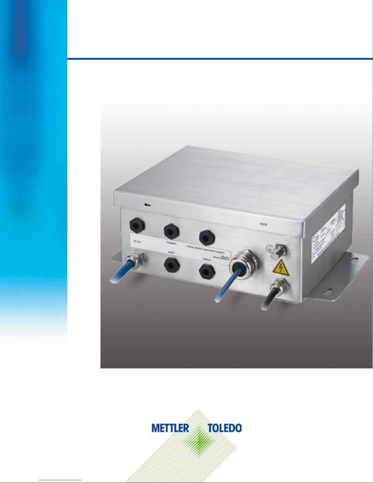
ACM500
Communication Module
Installation Manual
Page 2

Essential Services for Dependable Performance of Your ACM500 Communication Module
Register your product
Contact METTLER TOLEDO for service
Installation, Configuration, Integration and Training
Initial Calibration Documentation
Periodic Calibration Maintenance
GWP® Verification
life-cycle management of weighing equipment
ACM500 Communication Module
Congratulations on choosing the quality and precision of METTLER TOLEDO. Proper use of your
new equipment according to this Manual and regular calibration and maintenance by our factorytrained service team ensures dependable and accurate operation, protecting your investment.
Contact us about a service agreement tailored to your needs and budget. Further information is
available at www.mt.com/service.
There are several important ways to ensure you maximize the performance of your investment:
1.
www.mt.com/productregistration so we can contact you about enhancements, updates and
important notifications concerning your product.
2.
accuracy – an out of specification scale can diminish quality, reduce profits and increase
liability. Time ly ser v ice from METTLER TOLEDO will ensure accuracy and optimize uptime and
equipment life.
: We invite you to register your product at
: The value of a measurement is proportional to its
a.
trained, weighing equipment experts. We make certain that your weighing equipment is
ready for production in a cost effective and timely fashion and that personnel are trained for
success.
b.
requirements are unique for every industrial scale so performance must be tested and
certified. Our calibration services and certificates document accuracy to ensure production
quality and provide a quality system record of performance.
c.
confidence in your weighing process and documentation of compliance with requirements.
We offer a variety of service plans that are scheduled to meet your needs and designed to
fit your budget.
d.
control and improvement of the entire measuring process, which ensures reproducible
product quality and minimizes process costs. GWP (Good Weighing Practice), the sciencebased standard for efficie n t
answers about how to specify, calibrate and ensure accuracy of weighing equipment,
independent of make or brand.
: A risk-based approach for managing weighing equipment allows for
: The installation environment and application
: A Calibration Service Agreement provides on-going
: Our service representatives are factory-
, gives clear
Page 3
© METTLER TOLEDO 2016
No part of this man u al m ay be reproduced or transmitted in any form or by any means, elec t ro nic or
mechanical, including photocopying and recording, for any purpose without the express written
permission of METTLER TOLEDO.
U.S. Government Restricted Rights: This documentation is furnished with Restricted Rights.
Copyright 2016 METTLER TO L ED O . This d oc um entation contains proprie t ary i nf or m a ti o n of M ET TLER
TOLEDO. It may not be copied in whole or in part without the express written consent of METTLER
TOLEDO.
METTLER TOLEDO reserves the right to make refinements or changes to the product or manual
without notice .
COPYRIGHT
METTLER TOLEDO® is a registered tra de mark of Mettler-To l e do , LLC . Al l ot he r br an d or pr od uct
names are trademarks or regis t e r ed tr a de marks of their respective companies.
METTLER TOLEDO RESERVES THE RIGHT TO MAKE REFINEMENTS OR CHANGES
WITHOUT NOTICE.
FCC Notice
This device complies with Pa rt 15 of the FCC Rules and the R ad i o Interference Re quirements of the
Canadian Department of Communications. Operation is subject to the following conditions: (1) this
device may not cause harmful interference, and (2) this device must accept any interference
received, including interference that may cause undesired operation.
This equipment has been tested and fo u nd t o comply with the lim its fo r a Clas s A di gi t al de v i c e,
pursuant to P art 15 of FCC R u l e s. Thes e limits are desig ne d to provide reason ab l e pr o te ction agains t
harmful interference when the equipment is operated in a commercial environment. This equipment
generates, us e s , an d c a n radiate radio fre q ue ncy e nergy and, if not ins t al le d a nd used in
accordance with the instruction manual, may cause harmful interference to radio communications.
Operation of this equipment in a residential area is likely to cause harmful interference in which case
the user will be required to correct the interference at his or her expense.
Declaration of Conformity is located in Appendix A.
RoHS Compliance Statement.
§ The majority of o ur pr o d uct s f all within categories 8 and 9. Those categories currently do not fall
within the scope of the Directive 2002/95/EG (RoHS) of January 27, 2003. If our products are
intended for use in other products which themselves fall within the scope of the RoHS Directive,
compliance requirements have to be separately negotiated contractually.
§ Those products which fall within categories 1-7 and 10 will be in compliance with the EU RoHS
Directive from no later than July 1, 2006.
§ If it is not possible fo r tec h nical reasons t o re pl ac e any non-RoHS-compliant substances in any of
the above products as required, we plan to inform our customers in a timely manner
Statement regarding harmful substances
We do not make direct use of harmful materials such as asbestos, radioactive substances or
arsenic compounds. However, we purchase components from third party suppliers, which may
contain some of these substances in very small quantities.
Page 4
DO NOT INSTALL OR PERFORM ANY SERVICE ON THIS EQUIPMENT BEFORE THE AREA IN
Warnings and Cautions
• READ this manual BEFORE operating or servicing this equi pment and FOLLO W thes e
instructions carefully.
• SAVE this manual for future reference.
WARNING
WHICH THE IND560x IS LOCATED HAS BEEN SECURED AS NON-HAZARDOUS BY
PERSONNEL AUTHORIZED TO DO SO BY THE RESPONSIBLE PERSON AT THE CUSTOMER’S
SITE.
WARNING
THE ACM500 COMMUNICATION MODULE IS DESIGNED TO OPERATE IN, AND MUST BE
LOCATED IN, A SAFE AREA. ONLY THE FIBER OPTIC OR LOW POWER CURRENT LOOP SERIAL
INTERFACE CAN CONNECT INTO THE HAZARDOUS AREA WITHOUT ADDITIONAL BARRIERS OR
OTHER PROTECTION.
WARNING
ONLY THE COMPONENTS SPECIFIED IN THIS MANUAL CAN BE USED IN THIS DEVICE. ALL
EQUIPMENT MUST BE INSTALLED IN ACCORDANCE WITH THE INSTALLATION INSTRUCTIONS
DETAILED IN THIS MANUAL. INCORRECT OR SUBSTITUTE COMPONENTS AND/OR DEVIATION
FROM THESE INSTRUCTIONS CAN IMPAIR THE INSTRINSIC SAFETY OF THE TERMINAL AND
COULD RESULT IN BODILY INJURY AND/OR PROPERTY DAMAGE.
WARNING
ALLOW ONLY QUALIFIED PERSONNEL TO SERVICE THE ACM500. EXERCISE CARE WHEN
MAKING CHECKS, TESTS AND ADJUSTMENTS THAT MUST BE MADE WITH POWER ON.
FAILING TO OBSERVE THESE PRECAUTIONS CAN RESULT IN BODILY HARM AND/OR
PROPERTY DAMAGE.
WARNING
TO PREVENT IGNITION OF HAZARDOUS ATMOSPHERES, DISCONNECT THE IND560x FROM
POWER SOURCE BEFORE OPENING ACM500 ENCLOSURE. KEEP COVER TIGHTLY CLOSED
WHILE THE CIRCUIT IS ENERGIZED. DO NOT OPEN WHEN AN EXPLOSIVE DUST ATMOSPHERE
IS PRESENT.
WARNING
BEFORE PUTTING THE ACM500 INTO SERVICE, MAKE SURE THE PROTECTIVE COVER IS
INSTALLED PROPERLY OVER THE INTERFACE BOARD. THIS PROTECTIVE COVER IS PART OF
THE SAFETY APPROVAL FOR THE ACM500 CONNECTIONS INTO THE HAZARDOUS AREA. NO
WIRES FROM THE COM4 OR COM5 CONNECTION CAN CONTACT THE ACM500 MAIN BOARD
OR ANY OF THE OPTION BOARDS.
Page 5
In conformance with the European Directive 2002/96/EC on Waste Electrical and Electronic
WARNING
FOR CONTINUED PROTECTION AGAINST SHOCK HAZARD, CONNECT TO PROPERLY
GROUNDED POWER SOURCE ONLY. DO NOT REMOVE THE GROUNDING CONNECTION.
WARNING
BE CERTAIN THAT THE COMMUNICATION CIRCUITS ARE WIRED EXACTLY AS SHOWN IN THE
INSTALLATION SECTION OF THIS MANUAL. IF THE WIRES ARE NOT CONNECTED CORRECTLY,
THE IND560x TERMINAL OR INTERFACE BOARD MAY BE DAMAGED.
WARNING
WHEN THIS EQUIPMENT IS INCLUDED AS A COMPONENT PART OF A SYSTEM, THE
RESULTING DESIGN MUST BE REVIEWED BY QUALIFIED PERSONNEL WHO ARE FAMILIAR
WITH THE CONSTRUCTION AND OPERATION OF ALL COMPONENTS IN THE SYSTEM AND THE
POTENTIAL HAZARDS INVOLVED. FAILURE TO OBSERVE THIS PRECAUTION COULD RESULT IN
BODILY HARM AND/OR PROPERTY DAMAGE.
NOTICE
Warnings and Cautions
OBSERVE PRECAUTIONS FOR HANDLING ELECTROSTATIC SENSITIVE DEVICES.
Disposal of Electrical and Electronic Equipment
Equipment (WEEE) this device may not be disposed of in domestic waste. This also applies
to countries outside the EU, per their specific requirements.
Please dispos e o f this product in acc or dance with loca l re gu l at ions at the collec t in g po int
specified for electrical and electronic equipment.
If you have any questions, please contact the responsible authority or the distributor from
which you purchased this device.
Should this dev ic e be pas s ed on to other part ie s (f or private or profess ional use), the
content of this r egulation mus t also be related.
Thank you for your contribution to environmental protection.
Page 6

64061976 | 06 | 10/2016
METTLER TOLEDO ACM500 Installation Manual
1
Contents
1 Introduction ................................................................................. 1-1
1.1. ACM500 Versions ......................................................................... 1-1
1.1.1. 10BStandard ACM500 Features .................................................................................. 1-1
1.2. 1BWarnings and Precautions ............................................................. 1-2
1.3. 3BOperating Environment .................................................................. 1-3
1.3.1.1. Temperature and Humidity ................................................................................................ 1-3
1.3.1.2. Environmental Protection ................................................................................................... 1-3
1.3.1.3. Hazardous Areas.............................................................................................................. 1-3
1.4. 4BInspection and Contents Checklist ................................................... 1-3
1.5. 5BPhysical Dimensions ..................................................................... 1-4
1.6. 6BSpecifications ............................................................................... 1-4
1.7. 7BMain PCB .................................................................................... 1-5
1.8. 8BIntrinsically Safe Serial Interfaces .................................................... 1-5
1.8.1. Fiber Optic Interface ............................................................................................. 1-5
1.8.2. Intrinsically S afe C u rre n t L oop I nte r face .................................................................. 1-5
1.9. 9BOptions ........................................................................................ 1-6
1.9.1. 11BEthernet/COM2/COM3 Ports .................................................................................. 1-6
1.9.2. 12BPLC Interfaces ..................................................................................................... 1-6
1.9.2.1. Analog Output .................................................................................................................. 1-6
1.9.2.2. Allen-Bradley (A-B) RIO .................................................................................................... 1-6
1.9.2.3. DeviceNet ........................................................................................................................ 1-7
1.9.2.4. EtherNet/IP ...................................................................................................................... 1-7
1.9.2.5. Modbus TCP .................................................................................................................... 1-7
1.9.2.6. PROFIBUS DP .................................................................................................................. 1-7
2 Approvals .................................................................................... 2-1
2.1. Testing Standards ......................................................................... 2-1
2.2. Approval Parameters ..................................................................... 2-2
2.2.1. Intrinsically S afe C u rre n t L oop I nte r face .................................................................. 2-2
2.2.2. Fiber Optic Interface ............................................................................................. 2-3
2.3. United States Approval ................................................................... 2-3
2.4. European ATEX Approval ................................................................ 2-3
2.5. IECEx Approval ............................................................................. 2-4
2.6. Entity and Voltage Values, ATEX and IECEx ....................................... 2-4
2.7. Canadian Approval ....................................................................... 2-5
3 Installation .................................................................................. 3-1
3.1. Opening the Enclosure ................................................................... 3-2
3.2. AC Power Considerations ............................................................... 3-3
3.3. Mounting the Enclosure ................................................................. 3-3
Page 7

2
METTLER TOLEDO ACM500 Installation Manual
64061976 | 06 | 10/2016
3.4. Installing Cables and Glands .......................................................... 3-4
3.4.1. Ferrites ............................................................................................................... 3-4
3.4.2. Cable Glands ...................................................................................................... 3-5
3.5. Wiring Connections ....................................................................... 3-7
3.5.1. Interface Board Wiring Connections ....................................................................... 3-7
3.5.1.1. Fiber Optic Interface Conne c tions ........................................................................................ 3-7
3.5.1.2. I.S. Serial Interface Connection ........................................................................................... 3-9
3.5.1.3. Creating Cables for the I.S. Current Loop Connection ........................................................... 3-11
3.6. Wiring Connections for ACM500 Options ....................................... 3-12
Contents
3.6.1. Ethernet, COM2, and COM3 Connections ............................................................. 3-13
3.6.2. Analog Output Connection .................................................................................. 3-16
3.6.3. PROFIBUS DP Connection .................................................................................. 3-17
3.6.4. Allen-Bradley RIO Connection ............................................................................. 3-18
3.6.5. DeviceNet Connection ........................................................................................ 3-19
3.6.6. EtherNet/IP and Modbus TCP Interface ................................................................. 3-20
3.7. Bonding and Grounding............................................................... 3-20
3.8. PCB Switch and Jumper Settings .................................................. 3-21
3.9. Weights and Measures Sealing ..................................................... 3-22
3.10. Final Steps ................................................................................. 3-22
A Appendix / Apéndice / Anhang / Annexe / Appendice / Anexo .................... A-1
A.1. Overview of Approvals ................................................................... A-1
A.1.1. Un ited States Certificate ........................................................................................ A-1
A.1.2. Canadian Certificate ............................................................................................. A-1
A.1.3. Control Drawing .................................................................................................. A-1
A.1.4. Eu ro pean Certific ate (ATEX) .................................................................................. A-1
A.1.5. IE CEx C er t if ic ate .................................................................................................. A-1
A.2. Generalidades y aprobaciones ........................................................ A-2
A.2.1. Certificado de los Estados Unidos ......................................................................... A-2
A.2.2. Certificado de Canadá .......................................................................................... A-2
A.2.3. Diagrama de control ............................................................................................ A-2
A.2.4. Certificado Eur o pe o (ATEX) ................................................................................... A-2
A.2.5. Certificado IECEx ................................................................................................. A-2
A.3. Überblick der Zula ssungen ............................................................. A-2
A.3.1. US-Zertifikat ........................................................................................................ A-2
A.3.2. Kanadisches Zertifikat .......................................................................................... A-3
A.3.3. Kontrollzeichnung ............................................................................................... A-3
A.3.4. Europäisches Zertifikat (ATEX) .............................................................................. A-3
A.3.5. IECEx Zertifikat .................................................................................................... A-3
A.4. Synthèse des approbations ............................................................ A-3
A.4.1. Cer t if ic a t Ét ats-Unis .............................................................................................. A-3
A.4.2. Certificat canadien ............................................................................................... A-3
A.4.3. Schéma de contrôle ............................................................................................. A-3
A.4.4. Certificat européen (ATEX) .................................................................................... A-4
Page 8

64061976 | 06 | 10/2016
METTLER TOLEDO ACM500 Installation Manual
3
A.4.5. Certificat IECEx .................................................................................................... A-4
A.5. Panoramica ................................................................................. A-4
A.5.1. Certificazione degli Stati Uniti ................................................................................ A-4
A.5.2. Autorizzazio ne de l Ca n ad a ................................................................................... A-4
A.5.3. Schema di controllo ............................................................................................. A-4
A.5.4. Certificazione Europea (ATEX) ............................................................................... A-4
A.5.5. Cer t if ic az io ne IE CEx ............................................................................................. A-5
A.6. Visão Geral das Aprovações ........................................................... A-5
A.6.1. Certificado dos Estados Unidos ............................................................................. A-5
A.6.2. Certificado Canadense ......................................................................................... A-5
A.6.3. Desenho de Controle ........................................................................................... A-5
A.6.4. Certificado Europeu (ATEX) ................................................................................... A-5
A.6.5. Certificado IECEx ................................................................................................. A-5
A.7. United States Certificate .................................................................. A-6
A.8. Canadian Certificate ...................................................................... A-8
A.9. Control Drawing .......................................................................... A-10
A.10. European Certificate (ATEX) .......................................................... A-12
A.11. IECEx Certificate .......................................................................... A-15
A.12. Declaration of Conformity ............................................................. A-20
Page 9

64061976 | 06 | 10/2016
METTLER TOLEDO ACM500 Installation Manual
1-1
This chapter covers
• Options
1 Introduction
Thank you for purchasing the ACM500 communication module. The ACM500
• Versions of the ACM500
• Warnings and Precautions
• Operating Enviro nm ent
• Inspection and Contents Chec k list
• Physical Dimensions
• Specifications
• Main PCB
• Intrinsically Safe Serial Interfaces
1.1. ACM500 Versions
The ACM500 communication module provides a stainless steel enclosure to house additional
options for the IND560x terminal. It is available with the fo llo win g in te rface types:
communication module provides housing for the additional serial ports, Ethernet
and PLC options of the IND560x terminal. While the IND560 x te rminal is
designed to operate within Division 1 and Zone 1/21 areas, the ACM500 module
must be located in a safe area. The ACM500 module is approved for connection
to the IND560x using either a fibe r optic or an intrinsically safe current loop serial
interface.
Information about approvals, configuration, service and maintenance details are
included in this manual.
• Harsh enclosure with fiber optic interface
• Harsh enclosure with intrinsically safe current loop interface
1.1.1. 10BStandard ACM500 Features
• Stainless steel enclosure designed for washdown and dust tight protection
• Integral mounting bracket
• Cable glands and blanks to maintain the environmental integrity of the enclosure
• Internal universal power supply
• Dual channel fiber optic or intrin sically safe current loop inte rface
• Supports an optional Ethernet/COM2/ C O M3 in terface for the IND560x
• Support of the following PLC option boards for the IND560x:
• Analog Output • Allen-Bradley (A-B) RIO • DeviceNet
• EtherNet/IP • PROFIBUS
For information regarding METTLER TOLEDO Technical Training contact:
DP • Modbus TCP
Page 10
1-2
METTLER TOLEDO ACM500 Installation Manual
64061976 | 06 | 10/2016
DO NOT INSTALL OR PERFORM ANY SERVICE ON THIS EQUIPMENT BEFORE THE AREA IN
METTLER TOLEDO US
1900 Polaris Parkway
Columbus, Ohio 43240
Phone (US and Canada): (614) 438-4511
Phone (International): (614) 438-4888
HUwww.mt.comU
METTLER TOLEDO (Europe)
Postfach 250
D-72423 Albstadt, Germany
Phone: (+49-7431) 140
Introduction
HUwww.mt.comU
1.2. 1BWarnings and Precauti ons
Please read these instructions carefully before putting the new ACM500 module into operation.
Although the ACM500 communication module is ruggedly constructed, it is nevertheless a precision
instrument. Use care in handling and installing it.
WARNING
WHICH THE IND560x IS LOCATED HAS BEEN SECURED AS NON-HAZARDOUS BY
PERSONNEL AUTHORIZED TO DO SO BY THE RESPONSIBLE PERSON AT THE CUSTOMER’S
SITE.
WARNING
ONLY THE COMPONENTS SPECIFIED IN THIS MANUAL CAN BE USED IN THIS DEVICE. ALL
EQUIPMENT MUST BE INSTALLED IN ACCORDANCE WITH THE INSTALLATION INSTRUCTIONS
DETAILED IN THIS MANUAL. INCORRECT OR SUBSTITUTE COMPONENTS AND/OR DEVIATION
FROM THESE INSTRUCTIONS CAN IMPAIR THE INSTRINSIC SAFETY OF THE TERMINAL AND
COULD RESULT IN BODILY INJURY AND/OR PROPERTY DAMAGE.
WARNING
THE ACM500 COMMUNICATION MODULE IS DESIGNED TO OPERATE IN, AND MUST BE
LOCATED IN, A SAFE AREA. ONLY THE FIBER OPTIC OR LOW POWER CURRENT LOOP SERIAL
INTERFACE CAN CONNECT INTO THE HAZARDOUS AREA WITHOUT ADDITIONAL BARRIERS OR
OTHER PROTECTION.
Page 11

64061976 | 06 | 10/2016
METTLER TOLEDO ACM500 Installation Manual
1-3
1.3. 3BOperating Environment
ACM500 Communication Module
Bag of miscellaneous parts
When selecting a location:
• Choose a stable, vibration-free surface to mount the module
• Ensure there are no excessive fluctuations in temperature
• Be certain the cable glands and blanks are properly sealed to maintain the integrity of the
enclosure.
1.3.1.1. Temperature and Humidity
The ACM500 can be operated at temperatures and relative humidity conditions as listed under
Operating Environment in
to 60° C (–4° to 140° F) at 10 to 95% relative humidity, non -condensing
1.3.1.2. Environmental Protection
The stainless steel enclosu r e is certified as IP66 and TYPE 4 and is designed to provide washdown
and dust-tight protection.
1.3.1.3. Hazar do us Ar e as
The ACM500 communication module must be located in a safe area. It is designed to connect to
the intrinsically s a fe IND5 6 0x te rm in a l o pe rating within an area classified as Division 1, Zone 1 or
Zone 21. Connection to the IND560x terminal is made with either a fibe r optic or intrinsically safe
current loop interface.
XTable 1-1X. The module can be stored at temperatures ranging from –20°
1.4. 4BInspection and Contents Checklist
Verify the contents and inspect the package immediately upon delivery. If the shipping container is
damaged, check for internal damage and file a freight claim with the carrier if necessary. If the
container is not damaged, remove the ACM500 module from its protective package, noting how it
was packed, and inspect each component for damage.
If re-shipping of the module is required, it is best to use the original shipping container. The
ACM500 communication module must be packed correctly to ensure its safe transportation.
The package should include:
•
• Printed Installation Manual
•
• Documentation CD (all documentation)
Page 12
1-4
METTLER TOLEDO ACM500 Installation Manual
64061976 | 06 | 10/2016
Enclosure Type
Dimensions (H × W × D)
Overall (Y x Z)
Shipping Weight
Environmental Protection
Operati n g Environmen t
Hazardo us Ar e as
Power
IND560x C om munications
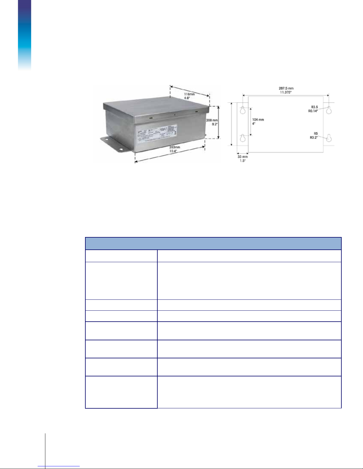
1.5. 5BPhysical Dimensions
The physical dimensions for the ACM500 communication module, for use with the IND560x, are
listed in
XTable 1-1X. The mounting measurements are shown in XFigure 1-1X in mm and inches.
Introduction
Figure 1-1: ACM500 Communication Module Dimensions
1.6. 6BSpecifications
The ACM500 communication module, for use with the IND560x terminal conforms to the
specifications listed in
XTable 1-1X.
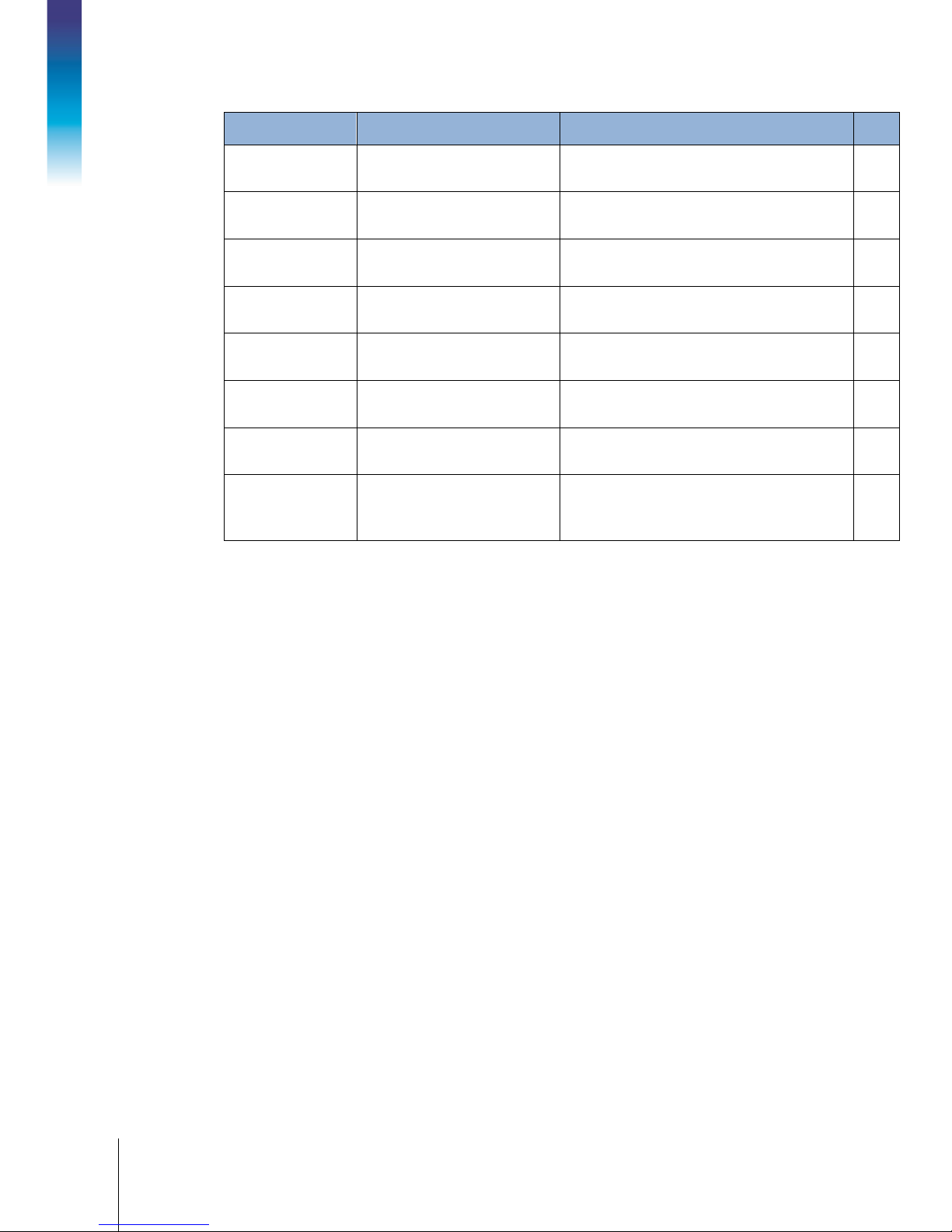
Table 1-1: ACM500 Specifications
ACM500 Specifications
Type 304L stainless steel enclosure
208 mm × 263 mm × 116 mm
(8.2 in. × 10.4 in. × 4.6 in.)
320 mm × 217 mm
(12.6 in. x 8.5 in.)
5.5 kg (11.2 lb)
IP66, TYPE 4
Can be operated at temperatures ranging from −10° to 40° C (14° to 104°
F) at 10% to 95% relative humidity non-condensing.
Not designed for us e wi th in hazardous are as . T he ACM 5 0 0 m us t be located
in a non-hazardous environment.
Operates at 100-240 VAC, 50–60 Hz, 250 mA and includes power cord for
country of use.
Two fiber optic or intrinsically safe current loop interface circuits required for
full communication, but only 1 may be required for some applications. One
circuit is required for optional PLC and COM2/COM3 communications. The
other circui t is re q ui r ed for Ethernet .
Page 13

64061976 | 06 | 10/2016
METTLER TOLEDO ACM500 Installation Manual
1-5
ACM500 Specifications
Ethernet/COM2/COM3
PLC
Optional Ethernet/COM2/COM3 ports: Ethernet 10 Base-T with two additional
serial ports COM 2 (R S-232) and COM3 (RS-232/RS-422/RS-485) avai lab le
using an expansion slot.
Optional A-B RIO, PROFIBUS DP, DeviceNet, EtherNet/IP, Modbus TCP or
Analog outpu t av a il a ble us i n g an ex p a nsion slot.
1.7. 7BMain PCB
The ACM500 communication module’s main printed circuit board (PCB) provides expansion slots
for the IND560x serial/Ethernet and PLC options. The main board also contains power connections
from the power supply and data connections from the fiber optic or intrinsically safe serial interface
board. Some diagnostic LEDs are also provided.
1.8. 8BIntrinsically Safe Serial Interfaces
A fiber optic interface or an intr in s ically safe serial interface ma y be use d to co n nec t an IN D5 6 0x
terminal to the ACM500. If a du a l-channel fiber optic converter (from a previous 8141, 8525,
Puma, or ID3sTx installation ) is to be connected to an IND560x, the fibe r o p tic in terfac e must be
used.
1.8.1. Fiber Optic Interface
The fiber optic interface provides one or two channels of communication designed to use a hard
clad silica or a plastic optic a l fib e r cable. High speed transmitters and receivers are used to
increase the throughput of data. When combined with the ACM500 communication module and its
options, this permits remote (safe area) operation of COM2 and COM3 serial ports, Ethernet and
PLC interfaces, at distances up to 300 meters (1000 ft.). When used with the standard dualchannel fiber optic converter, this interface provides one or two additional bi-directional serial ports
(COM2 and COM3) at the same distance. If the plastic optical fiber cab le is used, the distance is
reduced to 40 meters (130 ft.).
1.8.2. Intrinsically Safe Current Loop Interface
The intrinsically safe current loop interface provides one or two channels of communication
designed to use standard multi-strand copper wire. Low power, high speed circuitry is used to
extend the distance of each circuit up to 300 meters (1000 ft.) when using two twisted pair 0.5
2
(20 GA) cable. When combined with the ACM500 communication module and its options,
mm
this permits remote (safe area) operation of COM2 and COM3 serial ports, Ethernet and PLC
interfaces.
Page 14

1-6
METTLER TOLEDO ACM500 Installation Manual
64061976 | 06 | 10/2016
1.9. 9BOptions
The following options are available for use in the ACM500.
1.9.1. 11BEthernet/COM2/COM3 Ports
The Ethernet/COM2/COM3 port option provides two additional serial ports and a TCP/IP Ethernet
port. The Ethernet TCP/IP port can be used to transmit a demand template or continuous data to
other devices. It can also be used for remote configuration and updating the firmware using the
METTLER TOLEDO InSite
transfer of tare and target tables and complete setup files is also supported.
program, and for direct access to data via a shared dat a server. FTP
Introduction
The COM2 port provides RS-232 communication at rates from 300 to 115.2k baud and the COM3
port supports the same baud rates and provides an RS-232, RS-422, or RS-485 connection.
When using COM2 or COM3 serial ports in the ACM500, it is recommended to use a network
transmission baud rate of at least 9,600 Baud. Using COM2 or COM3 serial ports with network
transmission baud rates of 4,800 Baud or less may result in continuous data lagging behind real
time conditions, or a delayed response to on-demand data requests (e.g., SICS requests).
1.9.2. 12BPLC Interfaces
The IND560x PLC interface options available through the ACM500 include Analog Output, A-B RIO,
DeviceNet, EtherNet/IP, Modbus-TCP and PROFIBUS DP.
1.9.2.1. Analog Output
Analog Output refers to the representation of an internal system variable using a proportional
electrical signal. Analog Output can be used to transmit a measured value, such as the gross or net
weight or a rate. Another use for the Analog Output is as a control signal for some external device,
such as a control valve, where the amount of valve opening is proportional to the analog signal
commanding its operation. Such outputs are usually used to control the flow rate of material into or
out of a vessel.
Both 0-10 volt DC and 4-20 mA signals are provided. Additional details of this interface can be
found in the PLC Interface Manual on the ACM500 Documentation CD.
1.9.2.2. Allen-Bradley (A-B) RIO
The A-B RIO option enables data exchange by bi-directional communications using the Discrete
Data Transfer or Block Transfer mode. The terminal provides a communication exchange with the
PLC approximately 20 tim es p er se c ond u tiliz in g th e Allen-Bradley Discrete Data Transfer protocol.
This communication is a high-sp eed, real-time message interface between the terminal and the PLC
for process control. Division, integer, and floating point values are supported.
The A-B RIO interface also supports Block Transfer mode for transmission of larger amounts of
data. Additional details of this interface can be found in the PLC Interface Manual on the ACM500
Documentation CD.
Page 15

64061976 | 06 | 10/2016
METTLER TOLEDO ACM500 Installation Manual
1-7
1.9.2.3. DeviceNet
DeviceNet is an RS-485 based network utilizing CAN chip technology. The network can be
configured to run up to 500Kbits per second depending on cabling and distances. Messages are
limited to 8 un-fragmented bytes. The IND560x implementation of DeviceNet does not support
fragmented messages - all messages are 8 bytes or shorter. The network is capable of supporting
up to 64 nodes including the master.
1.9.2.4. EtherNet/IP
EtherNet/IP, short for "EtherNet Industrial Protocol," is an open industrial networking standard that
takes advantage of commercial, off-the-shelf EtherNet communication chips and physical media.
This networking standard supports both implicit messaging (real-time I/O messaging) and explicit
messaging (message exchange). The protocol is supported by ControlNet International (CI), the
Industrial Ethernet Association (IEA) and the Open DeviceNet Vendor Association (ODVA).
1.9.2.5. Modbus TCP
Modbus/TCP is used to establish master-slave/client-server communication between intelligent
devices. It is an open standard network protocol, widely used in the industrial manufacturing
environment. The ModbusTCP protocol takes the Modbus instruction set and wraps TCP/IP around
it.
1.9.2.6. PROFIBUS DP
The IND560x Terminal communicates to a PROFIBUS-DP master according to DIN 19 245. The
PROFIBUS option consists of software that resides in the IND56 0x Terminal and a printed circ u it
board that installs in the ACM500 communication module to implement the data exchange.
Page 16

64061976 | 06 | 10/2016
METTLER TOLEDO ACM500 Installation Manual
2-1
This chapter covers
2 Approvals
This chapter provides information about safety approvals for the ACM500
• Overview
• Testing Standar ds
• Approval Parame ters
• U.S. Approval
• European ATEX Approval
• IECEx Approval
• Entity and Volt age Values, ATEX and IECEx
• Canadian Approval
2.1. Testing Standards
Table 2-1 shows the list of standards to which the ACM500 has been tested. The date of each
standard is also included.
communication module with intrinsically safe connections. Please read this
chapter thoroughly before beginning installation.
Appendix A at the end of this manual contains the approval certificates and
control drawings for the approvals. These documents should also be
reviewed before beginning the installation.
Table 2-1: Testing Standards
Directive Standard Description Date
Class 3600
Class 3610
Class 3810
ANSI/IEC 60529
C22.2.No. 157
C22.2.No. 142 Process control equipment 1990
C22.2.No. 1010.1
C22.2.No. 60529
Electrical equipment for us e in H az ar dous
(Classified) Locations, general requirements
Intrinsically safe apparatus and associated
apparatus for use in Cl ass I, II, and III,
Division 1 and Clas s I Zone 0 an d 1
Hazardous (Classified) locations
Electrical and electronic test, measuring and
process equipment
Degrees of prote ction provided by enclosur es
(IP Code)
Intrinsically safe and non-incendive equipment
for use in hazardous locations
Safety requirements for electrical equipment for
measureme nt , co n tr o l an d la b oratory use –
Part 1: General requirements
Degree of protection provided by enclosur e s
(IP Code)
1998
1999
2005
2004
1992
2004
2005
Page 17
2-2
METTLER TOLEDO ACM500 Installation Manual
64061976 | 06 | 10/2016
Directive Standard Description Date
94/9/EC Directive EN60079-0:2006
94/9/EC Directive EN60079-11:2007
2006/95/EC Low
Voltage Directive
2004/108/EC EMC
Approvals
Directive
2004/108/EC EMC
Directive
2004/108/EC EMC
Directive
2004/108/EC EMC
Directive
2002/95/EC RoHS
Directive
EN61010-1:2001 General requirements 2001
EN61010-6-2 Immunity for industrial environments
EN61010-6-3
EN61000-4-3 (10V/m)
EN61000-4-6 (10V/m)
2.2. Approval Parameters
Electrical apparatus for explosive gas
atmospheres – Part 0: General requirements
Explosive atmospheres – Par t 11 : Eq u ipm ent
protection by intrinsic safety “i”
Emission standard for residential, commercial
and light indus trial environments
Radiated, ra di o -frequency, electromagnetic
field immunity te s t
Immunity to conducted disturbances, induced
by radio-frequency fields
Restriction of the use of certain hazardous
substances in electrical and electronic
equipment
2006
2007
2.2.1. Intrinsically Safe Current Loop Interface
The ACM500 intrinsically safe current loop interface is approved using the entity value method of
evaluation. The entity parameters for each ACM500 approval can be found in the following sections
and also in the approval certificates in Appendix A. Refer to the approval documentation of the
device to be connected to the A C M50 0 for its entity parameters.
The following conditions must be met. Note that the input values on the left side of the equations
, V
below (U
• U
• I
• P
• C
• L
As an alternative to the direct Inductance calculation, the following inductance to resistance formula
may be substituted:
• L
, etc.) are associated with the ACM500 module.
i
max
or V
i
or I
i
≥ Po or Pt
i
+ C
i
+ L
i
a max.
Where L
≥ Uo or Voc
max
≥ Io or Isc
max
≤ Co or Ca
cable
≤ Lo or La
cable
/ Ra < L
cable
cable
/ R
cable
is the length-based inductivity value and R
of the cable used.
is the length-specific resistance
cable
Page 18

64061976 | 06 | 10/2016
METTLER TOLEDO ACM500 Installation Manual
2-3
2.2.2. Fiber Optic Interface
The ACM500 fiber optic interface is approved by limiting the maximum power applied to the fiber
optic cable. The power is restricted by design to 5mW maximum. This restriction is shown in the
approval certificates and control drawings in the Appendix.
2.3. United States A ppr ov al
This section lists appr o val de ta ils fo r the ACM500 when installed according to United States
requirements. The U.S. safety approvals are based upon entity values.
The ACM500 communication module has been evaluated and approved as:
Associated apparatus with intrinsically safe connections to Class I, Division 1, Groups A, B,
C, D, Class II, Division 1, Groups E, F, and G, Class III hazardous locations in accordance
with Entity Requirements and METTLER TOLEDO Control Drawing #72191600.
• AIS / I, II, III / 1 / ABCDEFG – 72191600; Entity; IP66
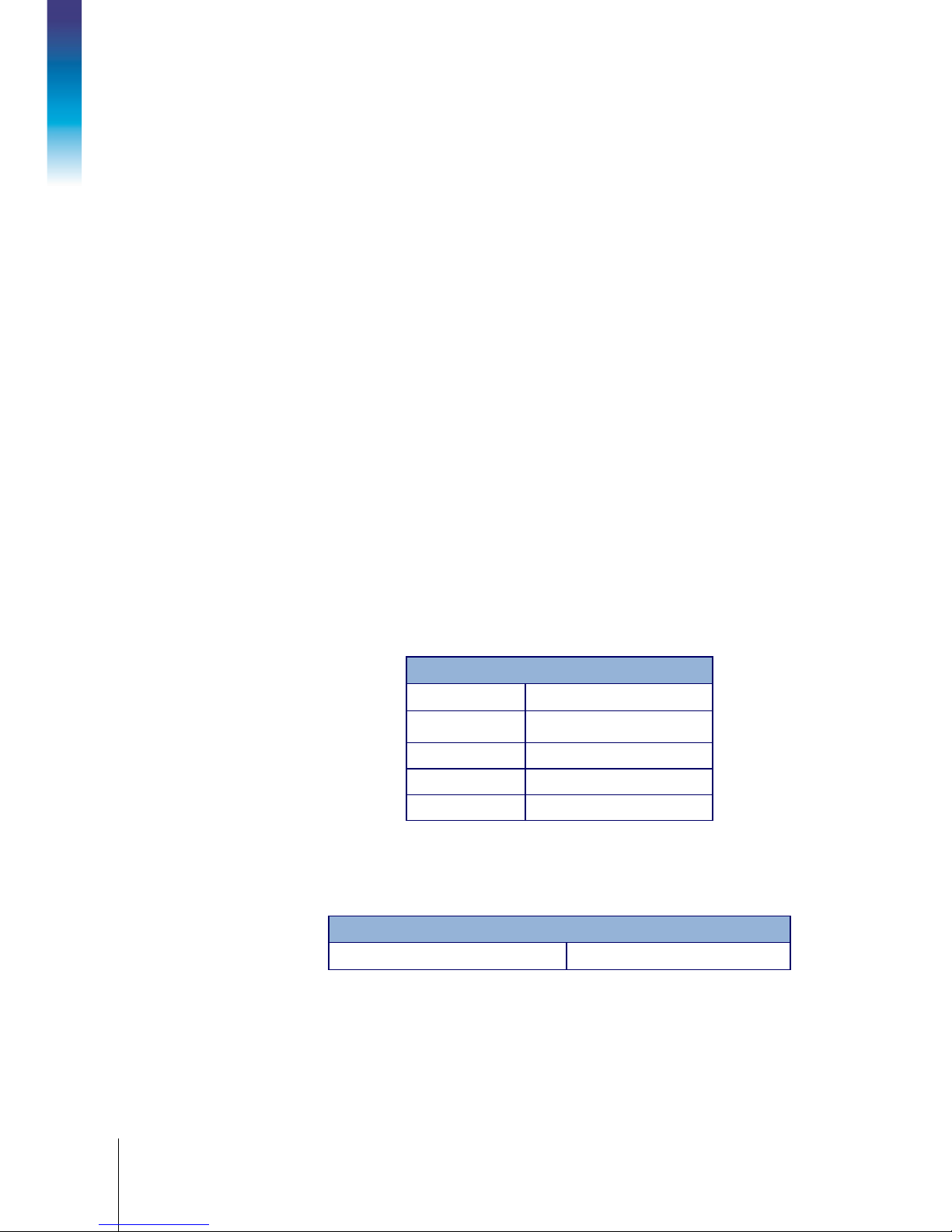
The approved entity parameters for the U.S. approval for the ACM500 module are listed in Table
2-2.
Table 2-2: Entity Values - U.S.
Entity Values for U.S. Approval
Ui 10 VDC
Ii 300 mA
Pi 500 mW
Ci 120 nF
Li 0 mH
2.4. European ATEX Approval
Approval details for the ACM500 communication module when installed according to European
ATEX requirements are listed in this section. The European safety approvals are based upon entity
values.
The ACM500 module has been evaluated and issued certificate BVS 08ATEX E 100 for certificatio n
as:
With Current Loop (CL) Interface
• II (2) G [Ex ib Gb] IIC
• II (2) D [Ex ib Db] IIIC
With Fiber Optic (FO) Interface
• II (2) G [Ex op is Gb] IIC
• II (2) D [Ex op is Db] IIIC
Page 19
2-4
METTLER TOLEDO ACM500 Installation Manual
64061976 | 06 | 10/2016
The approved entity parameters for European ATEX approval for the ACM500 intrinsically safe
communication module are listed in The approved entity parameters for IECEx approval for the
ACM500 intrinsically safe communication module are listed in
reference..
Table 2-3.
Error! Not a valid bookmark self-
2.5. IECEx Approval
Approvals
The ACM500 module has been evaluated for certification as:
With Current Loop (CL) Interface
• [Ex ib Gb] IIC
• [Ex ib Db] IIIC
With Fiber Optic (FO) Interface
• [Ex op is Gb] IIC
• [Ex op is Db] IIIC
2.6. Entity and Voltage Values, ATEX and IECEx
The approved entity parameters for IECEx approval for the ACM500 intrinsically safe communication
module are listed in
Error! Not a valid bookmark self-reference..
Table 2-3: Entity Values – ATEX and IEC Ex
Entity Values for ATEX and IECEx Approval
Ui 10 VDC
Ii 300 mA
Pi 500 mW
Ci 120 nF
Li 0 mH
The maximum voltage that can be applied to the ACM500 communication module is shown below
in Table 2-4. This is noted as the U
value on the label as part of the approval.
m
Table 2-4: Maximum Voltage
Maximum Voltage Listing for ATEX and IECEx Approval
Um 250 VAC
Page 20

64061976 | 06 | 10/2016
METTLER TOLEDO ACM500 Installation Manual
2-5
2.7. Canadian Approval
This section lists approval details for the ACM500 when installed according to Canadian
requirements. The Canadian safety approvals are based upon entity values.
The ACM500 communication module has been evaluated and approved as:
Associated apparatus with intrinsically safe connections to Class I, Division 1, Groups A, B,
C, D, Class II, Division 1, Groups E, F, and G, Class III hazardous locations in accordance
with Entity Requirements and METTLER TOLEDO Control Drawing #72191600.
• AIS / I, II, III / 1 / ABCDEFG - 72191600; Entity; IP66
The approved entity parameters for the Canadian approval for the ACM500 module are listed in
Table 2-5.
Table 2-5: Entity Values - Canada
Entity Values for Canadian Approval
Ui 10 VDC
Ii 300 mA
Pi 500 mW
Ci 120 nF
Li 0 mH
Page 21
64061976 | 06 | 10/2016
METTLER TOLEDO ACM500 Installation Manual
3-1
This chapter covers
3 Installation
This chapter provides installation instructions for the ACM500 communication
• Opening the Enclosure
• AC Power Considerations
• Mounting the Enclosure
• Installing Cables and Glands
• Interface Wiring Connections
• Wiring ACM500 Options
• Bonding and Grounding
• Switch Settings
• Weights and Measures Sealing
•
Final Steps
module, including wiring connections for the module and its options. Please read
this chapter thoroughly before beginning installation.
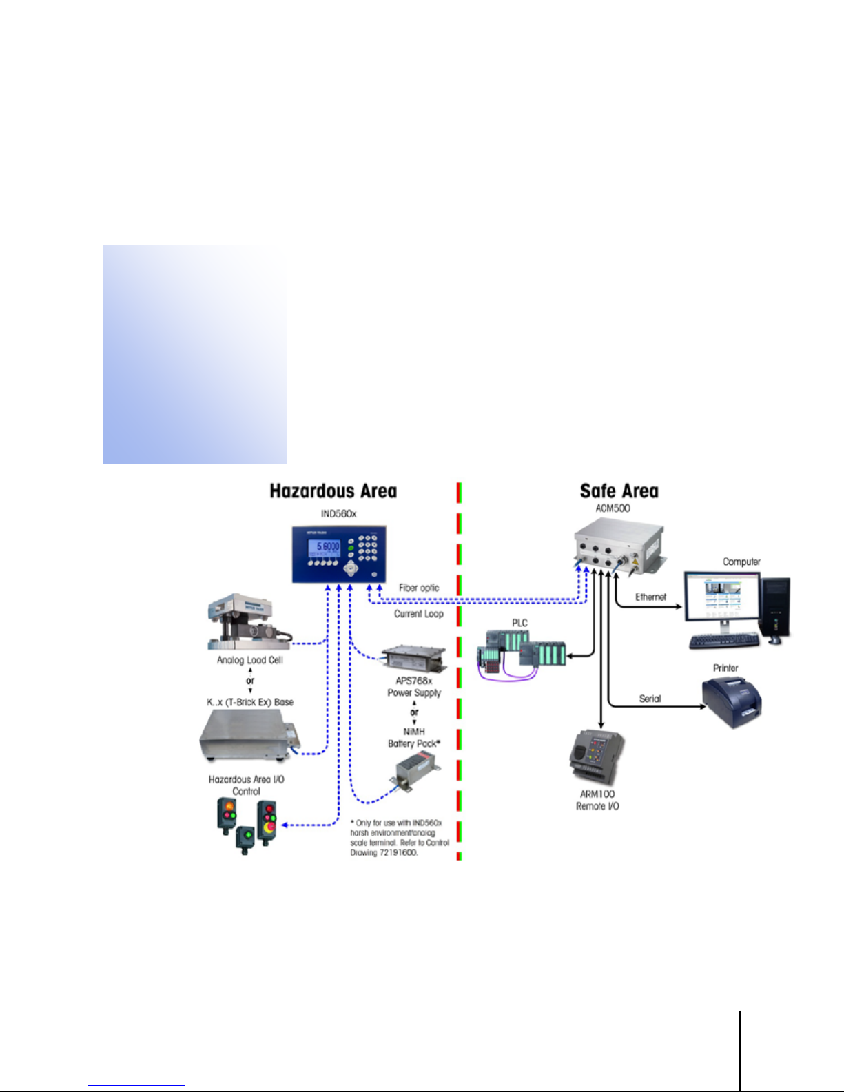
An illustration of a typic a l ACM50 0 in s ta lla tio n with an IND560x is shown in Figure
3-1. Note that the ACM500 must be located in the safe area. Refer to the approval
documents for additional information.
Figure 3-1: Typical ACM500 Installation
Page 22
3-2
METTLER TOLEDO ACM500 Installation Manual
64061976 | 06 | 10/2016
DO NOT INSTALL OR PERFORM ANY SERVICE ON THIS EQUIPMENT BEFORE THE AREA IN
3.1. Opening the Enclosure
WARNING
WHICH THE IND560x IS LOCATED HAS BEEN SECURED AS NON-HAZARDOUS BY
PERSONNEL AUTHORIZED TO DO SO BY THE RESPONSIBLE PERSON AT THE CUSTOMER’S
SITE.
WARNING
Installation
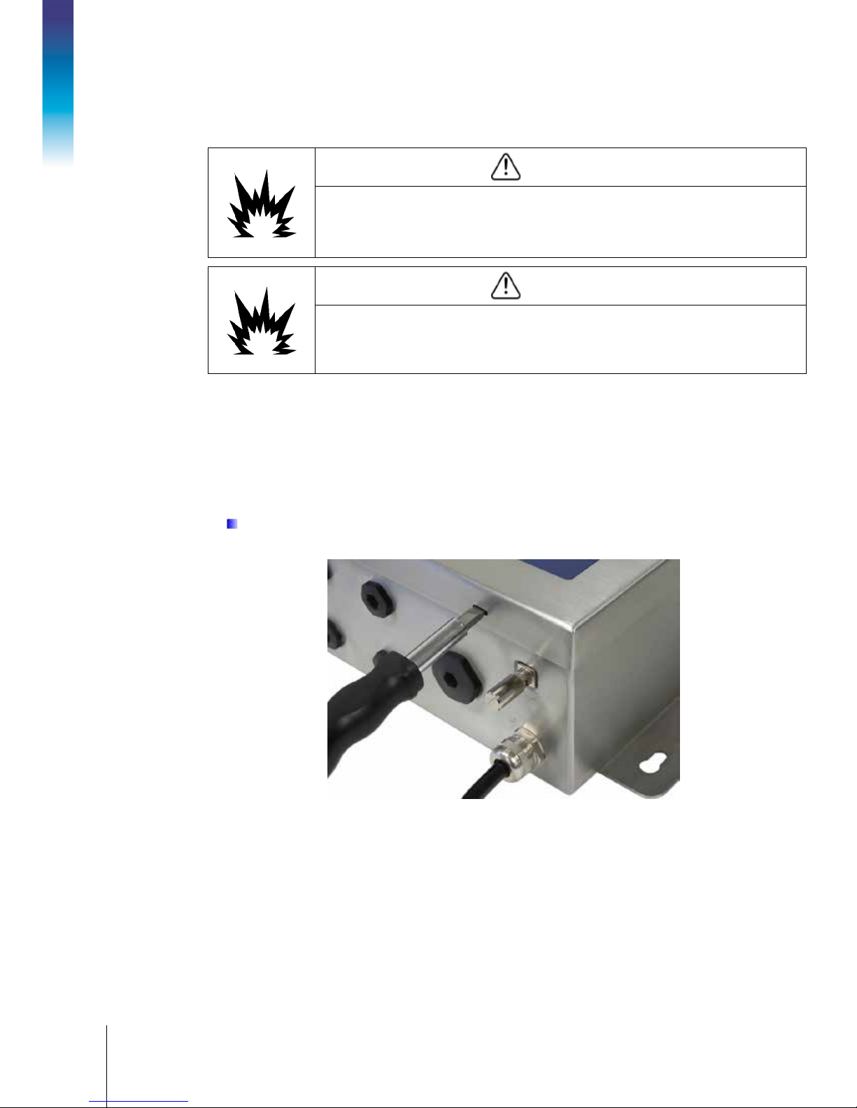
The front panel of the ACM500 is locked in place by four spring clips attached to the enclosure
body. To gain access for internal wiring and setting switches, separate the front panel from the
enclosure as follows:
1. Insert the tip of a flat-blade screwdriver into one of the two slots (toward the bottom of the slot)
located on the bottom of the front panel assembly (refer to Figure 3-2) and gently push in
toward the enclosure. A “pop” sound indicates when the cover is released.
TO PREVENT IGNITION OF HAZARDOUS ATMOSPHERES, DISCONNECT THE IND560x FROM
POWER SOURCE BEFORE OPENING ACM500 ENCLOSURE. KEEP COVER TIGHTLY CLOSED
WHILE THE CIRCUIT IS ENERGIZED. DO NOT OPEN WHEN AN EXPLOSIVE DUST ATMOSPHERE
IS PRESENT.
If the clip does not release easily, apply a small amount of force/pressure to the front cover
of the ACM500 and repeat Step 1.
Figure 3-2: Ope ning the Enclos ure
2. Repeat Step 1 for the other slot.
3. With the two spring clips re lea s e d, lift th e b o tto m o f th e fron t p a nel firmly up and out until it
completely clears the top edge of the bottom enclosure.
4. Squeeze the top of the front panel to the enclosure slightly and push upward to unsnap the two
remaining clips, then lift the panel to clear them. The panel will swing down, hinged by two
wire cables at the bottom.
Page 23
64061976 | 06 | 10/2016
METTLER TOLEDO ACM500 Installation Manual
3-3
3.2. AC Power Con s iderations
No internal wiring is required for AC power, since the ACM500 is supplied with an integra l p o wer
cord. When installing the ACM500, make sure the unit is near a properly grounded socket-outlet
and that the outlet is easily acc essible.
Make sure that the AC power source is within the operating range of the ACM500, 100 to 240 VAC.
3.3. Mounting the Enclosure
The ACM500 enclosure is designed to mount to a flat, vertical surface such as an instrument panel
or industrial enclosure or wall. Observe location and environment considerations as described in
Chapter 1 of this manual,
To mount the enclosure, follow these steps:
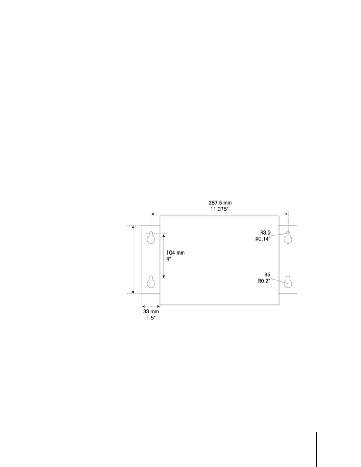
1. Mark the position of the mounting holes on the vertical surface using the dimensions shown in
Figure 3-3, or by holding the enclosure up to the surface and marking through the bracket
holes on the sides of the enclosure. Measurements are provided in mm and inches.
Introduction.
2. The hardware to mount the enclosure to the vertical surface is not included with the terminal – it
must be supplied locally. Ensure that the mounting hardware is capable of supporting the
weight of the terminal, wh ich is a pproximately 6 kg (13 lb). Using the lo c a lly-supplied
hardware, mount the ACM500 to the vertical surface.
Figure 3-3: Mounting Hole Pattern
Page 24
3-4
METTLER TOLEDO ACM500 Installation Manual
64061976 | 06 | 10/2016
3.4. Installing Cables and Glands
This section provides information for installing cables and connections to the ACM500
communication module, including:
• Ferrites
• Cable Glands
• Interface Board Wiring Connections
Installation
3.4.1. Ferrites
• Cable Preparation for Intrinsically Safe Current Loop Interface
• Wiring Connections for Options
WARNING
ONLY THE COMPONENTS SPECIFIED IN THIS MANUAL CAN BE USED IN THIS DEVICE. ALL
EQUIPMENT MUST BE INSTALLED IN ACCORDANCE WITH THE INSTALLATION INSTRUCTIONS
DETAILED IN THIS MANUAL. INCORRECT OR SUBSTITUTE COMPONENTS AND/OR DEVIATION
FROM THESE INSTRUCTIONS CAN IMPAIR THE INSTRINSIC SAFETY OF THE TERMINAL AND
COULD RESULT IN BODILY INJURY AND/OR PROPERTY DAMAGE.
In order to meet certain electrica l n o is e emission limits and to protect the AC M5 00 from ex te rn a l
influences, it is nece ssa ry to ins ta ll a ferrite core on the connection cab le between the interface
board and the main board of the ACM500.
Ferrites are not required on the incoming intrinsically safe current loop or fibe r o p tic interfaces.
Do not attempt to use ferrites on the fiber op tic c a b le for th e in te rface board. Attempting to
do so will damage the fiber optic cable
Additional ferrites are not required for the Ethernet TCP/IP, COM2/COM3 and PLC
connections running from the ACM500.
To install ferrites, simply pass the cable through the center of the core and then take one wrap
around the outside of the core and pass it through again. Either the complete cable or the individual
wires can be wrapped through the ferrite. This should be done on the inside of the enclosure as
close to the outside wall as pos s ib le . R e fer to Figure 3-4 for examples of acceptable methods of
installation.
Figure 3-4: Installing the Ferrite Cores
Page 25

64061976 | 06 | 10/2016
METTLER TOLEDO ACM500 Installation Manual
3-5
3.4.2. Cable Glands
The ACM500 stainless steel enclosure is designed to withstand wet and dusty environments. In
order to maintain the sealing integrity of the enclosure, care must be taken when installing cables
that enter the enclosure. To ensure a watertight and dust tight seal:
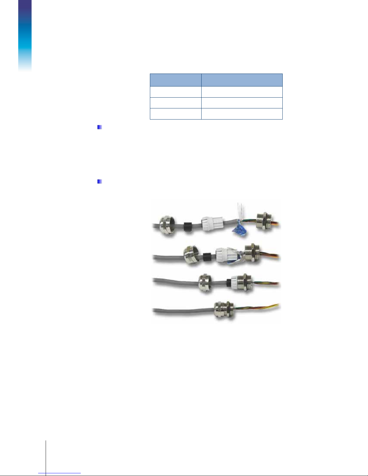
• Pass any cables through an appropriately sized cable grip before connecting the wires inside
the ACM500.
The intrinsically safe current loop interface cables and the fiber optic interface cable always
pass through the two cable glands “A” and “B” to the far left (Figure 3-5). Note that only
ATEX certified cable glands should be used on COM4 and COM5. Only the certified inserts
supplied with the ATEX glands can be used for securing cables. Do not use rubber sleeve
grommets with the ATEX certified glands.
A: COM4
B: COM5
Figure 3-5: Cable Glands
•
When making a connection with fiber optic interface cable, a special split grommet (Figure
3-6) will be provided. Each of the two fiber cables fits into one of the two holes in the grommet.
Figure 3-6: Installing Fiber Optic Cables in Cable Grip
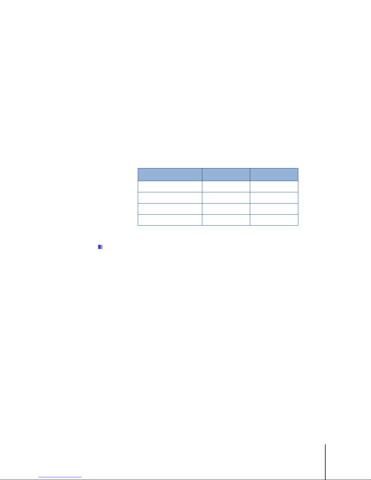
•
For all other ACM500 connections (Ethernet, serial, PLC), depending upon the diameter of the
cable used for a specific connection, a rubber sleeve grommet may be needed to properly seal
Page 26
3-6
METTLER TOLEDO ACM500 Installation Manual
64061976 | 06 | 10/2016
around the cable. Use one of the 2 different sized rubber sleeved grommets supplied with the
option kit to properly seal around the cable (Table 3-1).
Table 3-1: Grommet Cable Sizes
Grommet Cable Diameter
None 7–10 mm (0.28–0.39 in.)
Larger size hole 5– 6 mm (0.20–0.24 in.)
Smaller size hole 3–4 mm (0.12–0.16 in.)
Installation
Note that the rubber sleeve grommets provided in accessory kits cannot be used with ATEX
certified cable glan d s req u ire d fo r C OM4 and CO M5. O nly th e special split grommet
provided with the fiber optic interface is permitted.
• All cables that include shields (except the current loop interface cabling) should have the shield
terminated at the gland as shown in Figure 3-7. Spread the shield wires out and make sure
enough shield wire is present to make good contact with the metal part of the gland.
Note that the shield of the cable fr om th e IND5 6 0x to the ACM500 must not be terminated
at the ACM500 end. The shield must be left open at the ACM500 end of the cable.
•
After making the wiring connections as described in the next section, ensure the nut on the
cable gland is tightened properly to seal around the cable.
Figure 3-7: Shield Termination at Cable Gland
Page 27
64061976 | 06 | 10/2016
METTLER TOLEDO ACM500 Installation Manual
3-7
3.5. Wiring Connections
The following sections describe how to make wiring connections to the ACM500 communication
module. Follow all instr u c tions carefully.
3.5.1. Interface Board Wiring Connections
Depending on the model ordered, each ACM500 will have either the fiber optic serial interface board
or the intrinsically safe current loop interface board installed. After the ACM500 enclosure is open,
the interface board can be removed and connections made as described in the next sections.
Each interface board provides two circuits for communication to the IND560x. Depending upon the
options used, it may not be necessary to provide connections to both circuits. Refer to Table 3-2 to
determine if both the COM4 and th e COM5 c irc u its must be connected.
Table 3-2: ACM500 Interface Port Usage
ACM500 Option Used COM4 Required COM5 Required
COM2 Port
COM3 Port
Ethernet --
PLC Option
3.5.1.1. Fiber Optic Interface Connections
When using fiber optic cable to connect the IND560x to the ACM500 communications
module, care must be taken not to bend the cable sharply or it could be permanently
damaged
The ACM500 does not include fiber optic cables to connect to the IND560x terminal. Fiber optic
cable is available separately from METTLER TOLEDO with pre-terminated connectors in various
lengths.
Two types of cable are offered for use with the ACM500:
• Plastic core
• Hard clad silica (glass) core
The plastic core fiber optic cable can be used for short cable runs up to 40m (125 ft.). For longer
cable runs, up to 300m (1000 ft.), the hard clad silica (glass) core cable must be used. Various
cable lengths for each type of cable are available. Please refer to your price pages and appropriate
catalogs for available lengths and part numbers.
ü
ü
ü
--
-ü
--
If necessary, two glass core fiber optic cables can be coupled using a special optic coupler, but the
coupler signal loss is equivalent to 150 m (500 ft.) of cable. When one coupler is used the
useable distance of the glass core cable is reduced to 150 m (500 ft.)
It is possible to cut the plas tic c o re fib er o p tic ca b le in the fie ld a n d ins ta ll th e connectors using the
available terminatio n k it. The glass core fiber optic cable re q u ires special tools to install the
connectors and field termination of this cable is not recommended.
Page 28
3-8
METTLER TOLEDO ACM500 Installation Manual
64061976 | 06 | 10/2016
Two fiber optic cables are required for bidirectional communication to each port on the ACM500
(COM4 and COM5). If both ports are required, then a total of four cables will be required.
The fiber optic cable connectors and the sockets on the interface board are color-co ded. Each cable
has one blue and one gray end, which should be connected to the same color on the interface
board, as shown in Figure 3-8.
Installation
Figure 3-8: Color-Coded Fiber Optic Cable Connections
The following instructions assume that the fiber optic cables are already connected to the fiber optic
interface board in the IND560x and the other ends of the cables are available at the ACM500.
Depending upon the country of installation, special protection such as conduit seals may be
required. Refer to the control drawing, the approval certificates and local regulations to determine
what is required.
1. Make certain that power is removed from the ACM500 communication module and the
IND560x terminal.
2. Feed the ends of the fiber optic cables through the split bushing of the correct cable gland
(identified in (Figure 3-5) until the cable reach es the fiber optic interface bo ar d (a pproximately
90 mm/3.5 in.). The COM4 cables should enter through the upper cable gland “A”, the COM5
cables through cable gland “B” just below.
Be sure the fiber optic cable is not bent to less than a 13 mm (1/2 inch) radius. Any sharp
kinks in the fiber optic cable will damage it, requiring that the cable be replaced. Coil any
excess cable neatly in large loops close to the ACM500 and secure it so it does not get
damaged.
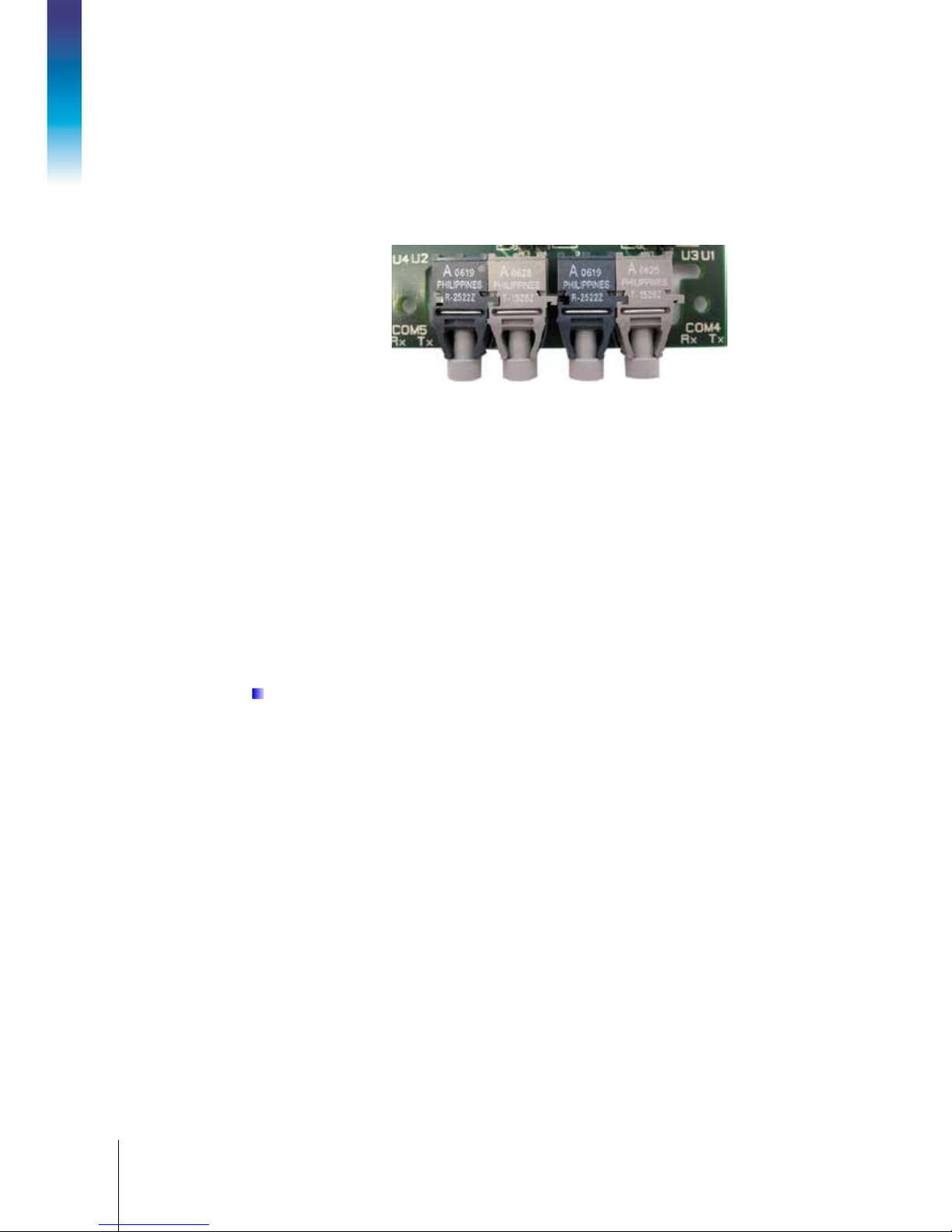
3. When connecting fiber optic cables to COM4, determine which two fiber optic cables come from
the COM4 port of the IND560x. Plu g the fiber optic cable from the IND560x COM4 transmitter
(U1) into the ACM500 COM4 receiver (U3) and the cable from the IND560x CO M4 receiver
(U3) into the ACM500 COM4 tran sm itte r (U1). Refer to Figure 3-9 to help identify the
transmitters and receivers on the ACM500 fiber optic interface board. Figure 3-10 shows
correct wiring between the IND560x and the ACM500.
Page 29
64061976 | 06 | 10/2016
METTLER TOLEDO ACM500 Installation Manual
3-9
U1- COM4 Tx
U3- COM4 Rx
U2- COM5 Tx
U4- COM5 Rx
Figure 3-9: Fiber Optic Interface Board
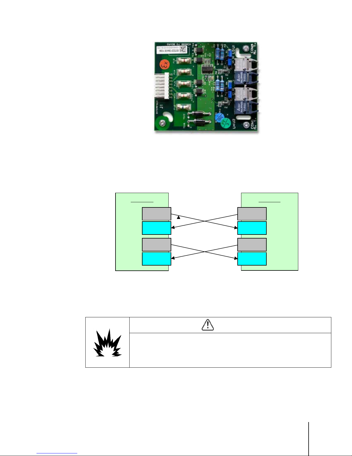
4. When installing a connection to COM5, determine which two fiber optic cables come from the
COM5 port of the IND560x . Plug the fib er optic cab le fr om the IND560 x COM5 transmitte r
into the ACM500 COM5 receiver
the ACM500 COM4 transmitter
(U4) and the cable from the IND560x COM5 receiver (U4) into
(U2). Figure 3-10 shows correct wiring between the IND560x
(U2)
and the ACM500.
IND560x ACM500
U1 – Tx
COM4
U3 - Rx
U2 – Tx
COM5
U4 - Rx
Figure 3-10: Fiber Optic Cable Connection Diagram
5. When all fiber optic cables are connected, tighten the compression nuts on the outside of the
cable glands to secure the cables in place.
6. Reinstall the protec tiv e cover and interface board assembly to the side of the ACM500.
BEFORE PUTTING THE ACM500 INTO SERVICE, MAKE SURE THE PROTECTIVE COVER IS
INSTALLED PROPERLY OVER THE INTERFACE BOARD. THIS PROTECTIVE COVER IS PART OF
THE SAFETY APPROVAL FOR THE ACM500 CONNECTIONS INTO THE HAZARDOUS AREA. NO
WIRES FROM THE COM4 OR COM5 CONNECTION CAN CONTACT THE ACM500 MAIN BOARD
OR ANY OF THE OPTION BOARDS.
3.5.1.2. I.S. Serial Interface Connection
U1 – Tx
COM4
U3 - Rx
U2 – Tx
COM5
U4 - Rx
WARNING
The ACM500 does not include cables to connect to the IND560x terminal.
One length of cable is required for each circuit used. Refer to Table 3-2 to determine if one or two
circuits are required for your application. Connection cables are available separately from METTLER
Page 30
3-10
METTLER TOLEDO ACM500 Installation Manual
64061976 | 06 | 10/2016
TOLEDO in various lengths. Please refer to your price pages and appropriate catalogs for available
lengths and part numbers. Maximum connection length is 300 m (985 ft).
The following instr uctio n s assume that pre-made connection cables are already available, and
describe how to connect the ACM500 end of the intrinsically safe interface cable. Refer to the
IND560x installation manual for details on the terminal end of the cable. Depending upon the
country of installation, special cable protection such as conduit seals may be required. Refer to the
control drawing, the approval certificates and local regulations to determine what is required.
1. Make certain that power is removed from both the IND560x terminal and the ACM500
communication module.
Installation
2. Feed the cables through the correct cable gland (identified in Figure 3-5) until the wires re a ch
the intrinsically s a fe cur re n t loop interface board (approximately 90 mm – 3.5 in.). The COM4
cable should enter through the upper cable gland “A” and the COM5 cable should enter through
cable gland “B” just below.
WARNING
BE CERTAIN THAT THE COMMUNICATION CIRCUITS ARE WIRED EXACTLY AS SHOWN IN THE
INSTALLATION SECTION OF THIS MANUAL. IF THE WIRES ARE NOT CONNECTED CORRECTLY,
THE IND560x TERMINAL OR INTERFACE BOARD MAY BE DAMAGED.
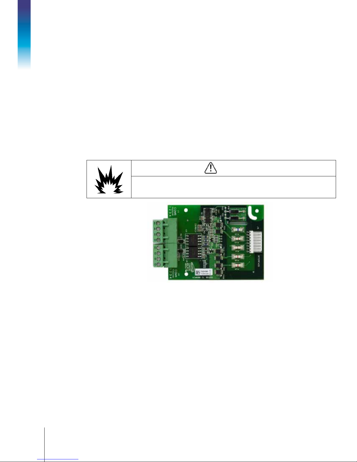
Figure 3-11: Current Loop Interface Board
3. When installing a connection to COM4, determine which cable comes from the COM4 port (J4)
of the IND560x. This cable will con n ect to COM4 (
4. Follow the wiring connections shown in Figure 3-12 and Table 3-3. Refer to Figure 3-11 to
help identify the terminal positions. Keep the internal wiring as short as practical.
J4) of the ACM500.
Page 31

64061976 | 06 | 10/2016
METTLER TOLEDO ACM500 Installation Manual
3-11
IND560x
ACM500
1
2
3
4
1
2
3
4
COM4
COM5
COM4
COM5
1
2
3
4
1
2
3
4
Figure 3-12: I.S. Serial Interface Wiring
5. When installing a connection to COM5, determine which cable comes from the COM5 port (J3)
of the IND560x. This cable will con n ect to COM5 (
J3) in the ACM500.
6. Follow the wiring connections shown in Figure 3-12 and Table 3-3. Refer to Figure 3-11 to
help identify the termin a l p ositio n s . Keep the internal wires as shor t as pr actic a l.
Table 3-3: COM4 and COM5 Port Wiring
IND560x
COM4 (J4)
Terminal #
1 1 1 1
ACM500
COM4 (J4)
Terminal #
IND560x
COM5 (J3)
Terminal #
ACM500
COM5 (J3)
Terminal #
2 2 2 2
3 3 3 3
4 4 4 4
7. After all interface cables are connected, reinstall the cover and interface board assembly to the
side of the ACM500 enclosure making sure that all wiring from the IND560x is contained under
the cover.
8. Tighten the compression nuts on the outside of the cable glands to secure the cables.
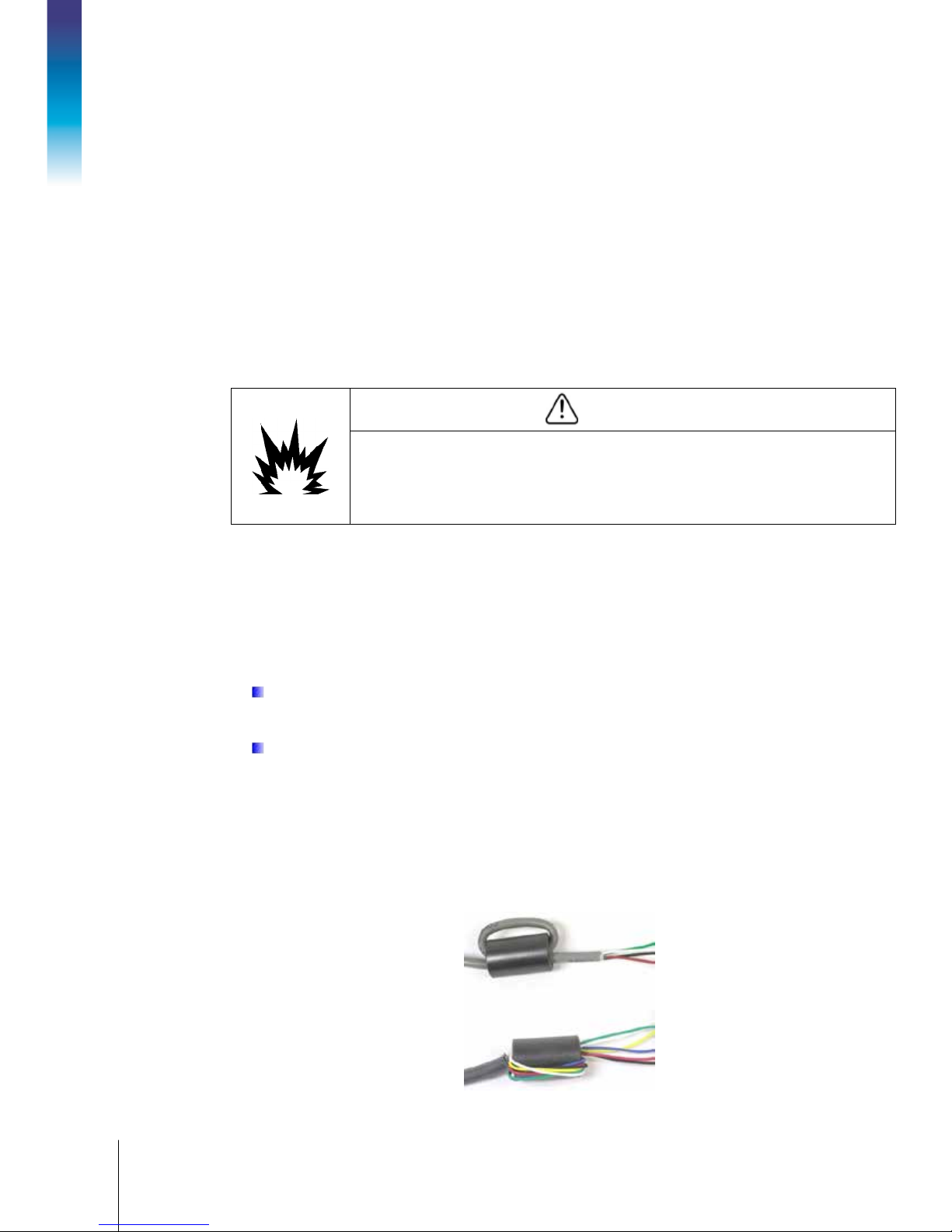
3.5.1.3. Creating Cables for the I.S. Current Loop Connection
Customer specific con n ectio n cables for the intrinsically safe current loop interface must be created
according to the following guidelines (Table 3-4 and Figure 3-13)
Each I.S. current loop interface cable used must contain two twisted pair conductors, and each
2
conductor must be a minimum of 0.5 mm
(20 GA or 0.032 AWG) in size. One length of cable is
required for each circuit used. Refer to Table 3-2 to determine if one or two circuits are required for
your application.
Table 3-4: Current Loop Cable DImensions
Cable Description Dimension A Dimension B Maximum Cable Length
2x2x0.5mm
2 twisted pair, 20GA or
0.032AWG
2
60 mm
(2.4 inches)
70 mm
(2.8 inches)
300 meters
(984 feet)
Page 32

3-12
METTLER TOLEDO ACM500 Installation Manual
64061976 | 06 | 10/2016
• Ethe rnet and COM2/COM3 Serial Ports
• Analog Output
• DeviceNet
• Allen-Bradley (A -B) RIO
• PROFIBUS DP
• EtherNet/IP and Modbus TCP
Wire end ferrules with plastic
collar, crimp connection required
for some regions
Installation
Figure 3-13: I.S. Serial Interface Wiring
IMPORTANT: Apply the cable shielding only on the IND560x end. Do NOT apply shielding
on the ACM500 end of the current loop connection cable.
WARNING
BEFORE PUTTING THE ACM500 INTO SERVICE, MAKE SURE THE PROTECTIVE COVER IS
INSTALLED PROPERLY OVER THE INTERFACE BOARD. THIS PROTECTIVE COVER IS PART OF
THE SAFETY APPROVAL FOR THE ACM500 CONNECTIONS INTO THE HAZARDOUS AREA. NO
WIRES FROM THE COM4 OR COM5 CONNECTION CAN CONTACT THE ACM500 MAIN BOARD
OR ANY OF THE OPTION BOARDS.
3.6. Wiring Connections for ACM500 Options
Options available for th e IND5 60 x terminal that are installed in the ACM500 and require external
connections include the following:
Figure 3-14 shows where each of these options is located in the AMC500. The connections for
each of these options are described in the following sections.
Page 33

64061976 | 06 | 10/2016
METTLER TOLEDO ACM500 Installation Manual
3-13
Figure 3-14: Option Locations in ACM500
3.6.1. Ethernet, COM2, and COM3 Connections
The Ethernet/COM2/COM3 option board is positioned in the top option slot on the ACM500 main
board. This option board provides a 10 Base-T connection (10 Mb) for Ethernet and two serial
ports labeled COM2 and COM3. The option board is shown in Figure 3-15 with the por ts identified.
COM2
connector
COM3
connector
Figure 3-15: Ethernet/COM2/COM3 Option Board
Ethernet
connector
Page 34

3-14
METTLER TOLEDO ACM500 Installation Manual
64061976 | 06 | 10/2016
The Ethernet connection is made via a standard RJ45 connector on the option board. The connector
location is indicate d in Figure 3-15.
If installing the Ethernet option, an Ethernet identification label is provided in the kit. This
label can be adhered to the ACM500 enclosure near the Ethernet connector, as shown in
Figure 3-16.
Installation
Figure 3-16: Ethernet Label Position
COM2 provides only RS-232. The COM2 signal names are listed in Table 3-5.
Table 3-5: COM2 Signal Names
Terminal Signal
TxD2 Transmit RS-232
RxD2 Receive RS-232
Gnd Logic Ground
An example of connecting external equipment to COM2 is shown in Figure 3-17.
Figure 3-17: Wiring to COM2
Page 35

64061976 | 06 | 10/2016
METTLER TOLEDO ACM500 Installation Manual
3-15
COM3 provides RS-232, RS-422 or RS-485 connections. The COM3 signal names are shown in
Table 3-6.
Table 3-6: COM3 Signal Names
Terminal Signal Notes
TxD Transmit RS-232
RxD Receive RS-232
Gnd Logic Ground
TxD3+ +Transmit RS-422, RS-485 Jumper to RxD3+ for RS-485
TxD3- -Transm it R S-4 22, RS-485 Jumper to RxD3- for RS-485
RxD3+ +Receive RS-422, RS-485 Jumper to TxD3+ for RS-485
RxD3- -Receive RS-422, RS-485 Jumper to TxD3- for RS-485
Some examples of connecting external equipment to COM3 are shown in Figure 3-18.
Figure 3-18: Wiring to COM3
Page 36

3-16
METTLER TOLEDO ACM500 Installation Manual
64061976 | 06 | 10/2016
3.6.2. Analog Output Connection
The analog output option fits into the lower (PLC) interface slot in the ACM500 main board. It
provides an analog signal of either 0-10 VDC or 4-20mA (but not both), proportional to the weight
applied to the scale or the rate of change of weight on the scale.
There are minimum and maximum resistance limits for the connecting device. These limits are
shown in Table 3-7.
Table 3-7: Resistance Limits
Interface Mini m um Resistance Maximum Resistance
Installation
0 - 10 VDC 100k Ω None
4 - 20 mA None 500 Ω
The maximum recommended cable length for the Analog Output connection is 15m (50 ft.). The
2
recommended cable for use with the analog output is shielded, two conductor stranded 0.5 mm
(20 GA or 0.032 AWG) cable (Belden #8762 or equivalent). This cable is available from METTLER
TOLEDO using part number 510220190. The analog output option board is shown in Figure 3-19.
Figure 3-19: Analog Output Option Board
Connections to the analog output board should be made as shown in Figure 3-20.
Figure 3-20: Wiring to the Analog Output
Page 37

64061976 | 06 | 10/2016
METTLER TOLEDO ACM500 Installation Manual
3-17
3.6.3. PROFIBUS DP Connection
The PROFIBUS PLC option fits into the PLC interface slot in the ACM500 main board. This option
board is shown in Figure 3-21.
The PROFIBUS connection to the ACM500 is made using a right-angle nine-pin connector inside the
enclosure. This connector is a standard Siemens part # 6ES7 972-0BA41-0XA0 or equivalent (not
supplied by METTLER TOLEDO). There are two nine-pin connectors on the PROFIBUS board – use
the lower of the two connectors shown in Figure 3-21. The completed connection is shown Figure
3-22.
Figure 3-21: PROFIBUS Option Board
Figure 3-22: PROFIBUS Connection in ACM500
Page 38

3-18
METTLER TOLEDO ACM500 Installation Manual
64061976 | 06 | 10/2016
Terminate the wires follo win g th e w iring instructions in Table 3-8, or the instructions included with
the connector.
Table 3-8: PROFIBUS Termination
9-Pin Connector Signal Name
1 Not Used
2 Not Used
3 RxD / TxD +
4 RTS
Installation
5 Gnd Bus
6 +5 V Bus
7 Not Used
8 RxD / TxD 9 Not Used
3.6.4. Allen-Bradley RIO Connection
The Allen-Bradley RIO PLC option fits into the PLC interface s lo t in the ACM500 main board.
Connections to the RIO option are made using a three-pin terminal connector on the RIO option.
Refer to the A-B RIO documentation for termination resistor values and other considerations. The AB RIO board is shown in Figure 3-23.
Figure 3-23: RIO Option Board
The part number recommended for the RIO cable is Belden 9463, sometimes referred to as "Blue
Hose" cable. This cable can also be purchased from METTLER TOLEDO using part number
64056504. The connection should be wired as shown in Figure 3-24.
Page 39

64061976 | 06 | 10/2016
METTLER TOLEDO ACM500 Installation Manual
3-19
3.6.5. DeviceNet Connection
The DeviceNet option board (Figure 3-25) is connected to the network by a DeviceNet-specific
twisted pair cable. The cable is a 2 twisted pair, shielded cable Belden part number 3082a or
2083a. An equivalent cable can be used.
The pin numbering of the DeviceNet option board connector, wire colors and functions are detailed
in Table 3-9.
Figure 3-24: RIO Connection
1 2 3 4 5
Figure 3-25: DeviceNet Option Board
Table 3-9: DeviceNet Signal N am es
For any additional DeviceNet wiring information required, refer to ODVA documentation or the ODVA
web site at: http://www.odva.org/.
Pin Signal Name Wire Color
1 V - Black
2 Can_L Blue
3 Drain Shield
4 Can_H White
5 V + Red
Page 40

3-20
METTLER TOLEDO ACM500 Installation Manual
64061976 | 06 | 10/2016
3.6.6. EtherNet/IP and Modbus TCP Interface
The EtherNet/IP Module (Figure 3-26) connects to the network via a standard Ethernet patch cable
with an RJ45 connector. The module’s address is set in software, and the DIP switches located on
the board are not used and must all be set to OFF.
Installation
Figure 3-26: EtherNet/IP Option Board
If installing the EtherNe t/IP option, an EtherNet/IP PLC label is pr o v id ed fo r c o nve n ience in
the kit. The label can be applied to the ACM500 enclosure near the EtherNet/IP connector,
as shown in Figure 3-16.
Figure 3-27: Ethernet Label Position
3.7. Bonding and Gro un din g
The equipotential bonding (EB) should be completed per specific local and country regulations. In
the United States, this is ANSI/NFPA 70, article 504 and ANSI/IA RP 12.06.01. In Canada this is the
Canadian Electrical Code C22.2. The equipotential bonding should be installed by an electrician
authorized by the equipment owner.
It must be ensured that the housings of all devices in an intrinsically safe system are connected to
the same potential via the EB grounding connection, and the neutral point for equipotential bonding
is as close to the weighing system as possible. In addition, no circulating current may flow via the
shielding of the intrins ically safe cabling.
Page 41

64061976 | 06 | 10/2016
METTLER TOLEDO ACM500 Installation Manual
3-21
The EB grounding lug on the ACM500 enclosure is shown in Figure 3-28 below.
Equipotential
connection
Figure 3-28: ACM500 Grounding Connection
3.8. PCB Switch and Jumper Settings
Four switches and one jumper are located on the Main PCB, as shown in Figure 3-29. Functions of
the switches are listed in Table 3-10. The W1 jumper is described in Figure 3-30 and Table 3-11.
bonding
Switch Function
K1-1 Not Used
K1-2 Flash Firmware
K1-3 Factory Test
K1-4 Not used
Figure 3-29: PCB Switch Positions
Table 3-10: Main PCB Switches Functions
Set in the OFF posit ion during norm a l ope ration
Set in the ON posit i on before beginning a firmware do w nload
Set in the OFF position at all times for normal operation
The ON positio n is us e d f or tes t in g in the manufact ur ing facility
Page 42

3-22
METTLER TOLEDO ACM500 Installation Manual
64061976 | 06 | 10/2016
1 2 3
Installation
Jumper Setting Description
1-2 This positio n is n ot us ed and should not be se le c ted
W1
2-3
Sets the Main Board to operate from the internal AC power supply. Should not need
modificati o n during installa t i o n .
Figure 3-30: W1 Jumper Posit io ns
Table 3-11: W1 Jum p er Description
3.9. Weights and Measures Sealing
The ACM500 does not contain any metrologically significant hardware or firmware, so sealing of
the ACM500 enclosure is not required in “Approved” or “Legal for Trade” applications.
3.10. Final Steps
After the fiber optic or I.S. serial interface has been connected to the IND560x and all options have
been installed into the ACM500 communication module, the final steps can be completed:
1. Make certain all wires from the I.S. current loop interface (if used) are contained within/behind
the protective cover.
2. Confirm all switches are in the OFF position and the Jumper is in the correct position.
3. Make sure the IND560x has been programmed to communicate with the ACM500 in the
Communications > Connections branch of the IND560x setup. Refer to the IND560x Technical
Manual for details.
4. Apply power to the ACM500.
5. Apply power to the IND560x.
The ACM500 must always be powered up first. Power up the IND560x after the ACM500. If
this sequence is not followed, communication between the terminal and the module cannot
be established.
6. Monitor the LEDs on the ACM500 main board as shown in Figure 3-31. If the ACM500 is
connected properly and the IND560x is programmed correctly, the LEDs will flash.
Page 43

64061976 | 06 | 10/2016
METTLER TOLEDO ACM500 Installation Manual
3-23
Figure 3-31: ACM500 Data LEDs Location (top) and detail (bottom)
7. After the IND560x has powered up, enter the Setup Menu tree and confirm that the options
installed in the ACM500 are av a ila b le for programming. If they are not, refer to the
IND560x
Technical Manual or the Service and Maintenance section, Chapter 3, of this manual for
troubleshooting assistance.
8. If everything is working correctly, reinstall the top cover on the ACM500 and press on each of
the corners of the cover until a “click” is heard. A “click” must be heard at each corner,
indicating the spring clips are engaged.
Page 44

ACM500
Módulo ce comunicaciones
Guía de instalación
Page 45

Servicios esenciales para el desempeño confiable
1. Registre su producto
Póngase en contacto con METTLER TOLEDO para obtener servicio
Instalación, configuración, integración y formación
Documentación de calibración inicial
Mantenimiento periódico de calibración
Verificación de GWP®: Un enfoque basado en el riesgo para manejar equipos de pesaje
ACM500 Módulo de comunicaciones
Enhorabuena por elegir la calidad y precisión de METTLER TOLEDO. El uso adecuado de su nuevo
equipo siguiendo este manual, y la calibración y mantenimiento regulares por parte del equipo de
servicio formado en fábrica garantizan un funcionamiento fiable y preciso, protegiendo su
inversión. Póngase en contacto con nosotros acerca del acuerdo de servicio ajustado a sus
necesidades y presupuesto. Hay más información disponible en www.mt.com/service.
Existen varias maneras importantes de garantizar que usted maximizará el rendimiento de su inversión:
para que podamos ponernos en contacto con usted si hubiera mejoras, actualizaciones y
notificaciones importantes relacionadas con su producto.
2.
proporcional a su precisión: una báscula fuera de las especificaciones puede disminuir la
calidad, reducir las ganancias y aumentar la responsabilidad. El servicio oportuno por parte de
METTLER TOLEDO garantizará precisión y optimizará el tiempo de funcionamiento y la vida útil
del equipo.
a.
reciben una capacitación en fábrica y son expertos en equipos de pesaje. Nos aseguramos
de que el equipo de pesaje esté listo para la producción de manera rentable y oportuna y
de que el personal esté formado para obtener resultados exitosos.
b.
instalación son únicos para cada báscula industrial. Su rendimiento se debe comprobar y
certificar. Nuestros servicios y certificados de calibración documentan la precisión para
garantizar la calidad en la producción y para proporcionar un registro de rendimiento del
sistema de calidad.
: Le invitamos a registrar su producto en www.mt.com/productregistration
: Los requisitos de aplicación y del entorno de
: El valor de una medida es
: Nuestros representantes de servicio
c.
confianza en el proceso de pesaje y documentación de cumplimiento de los requisitos.
Ofrecemos diversos planes de servicio que se programan para satisfacer sus necesidades
y están diseñados para ajustarse a su presupuesto.
d.
permite el control y mejora del proceso de medición completo, lo que asegura la calidad
reproducible del producto y minimiza los costos del proceso. GWP (Good Weighing
Practice [Buenas prácti cas de pe saj e]), el estándar basado en la ciencia para el manejo
eficiente del ciclo de vida del equipo de pesaje, ofrece respuestas claras acerca de cómo
especificar, calibrar y asegurar la precisión del equipo de pesaje, independientemente del
modelo o la marca.
: El acuerdo de servicio de calibración proporciona
Page 46

© METTLER TOLEDO 2016
Ninguna parte de este manual puede ser reproducida o transmitida en ninguna forma y por ningún
medio, electrónico o mecánico, incluyendo fotocopiado y grabación, para ningún prop ós i to s in
permiso por escrito de METTLER TOLEDO.
Derechos restringidos del Gobierno de los Estados Unidos: Esta documentación se proporciona con
Derechos Restringidos.
Derechos de autor 2016 METTLER TOLEDO. Esta document a ció n c on tiene información patent a da de
METTLER TOLEDO. Esta información no puede copiarse total o parcialmente sin el consentimiento
expreso por escrito de METTLER TOLEDO.
METTLER TOLEDO se reserva el derecho de refinar o cambiar el producto o el manual sin previo
aviso.
METTLER TOLEDO
nombres de productos son marcas comerciales o registradas de sus respectivas compañías.
METTLER TOLEDO SE RESERVA EL DERECHO DE HACER REFINACIONES O CAMBIOS SIN PREVIO
Este dispositivo cumple con la Parte 15 de las Pautas de la FCC y los Requerimientos de RadioInterferencia del Departamento Canadiense de Telecomunicaciones. La operación está sujeta a las
siguientes condiciones: (1) este dispositivo no puede causar interferencia dañina, (2) este
dispositivo debe aceptar cualquier interferencia recibida, incluyendo la interferencia que pueda
causar una operación indeseada.
Este equipo ha sido probado y se encontró que cumple con los límites para un dispositivo digital
clase A, consecuente con la Parte 15 de las Pautas de la FCC. Estos límites están diseñados para
proporcionar una protección razonable contra interferencia dañina cuando el equipo es operado en
un ambiente comercial. Este equipo genera, usa y puede irradiar frecuencias de radio y, si no es
instalado y utilizado de acuerdo con el manual de instrucciones, puede causar interferencia dañina
a las radiocomunicaciones. Es probable que la operac i ón de es te eq u ip o e n un área residenc ia l
cause interferencia dañina, en cuyo caso se le exigirá al usuario que corrija la interferencia con
gastos a su cargo.
®
es una marca registrada de Mettler-Toledo, LLC. Todas las demás marcas o
DERECHOS DE AUTOR
AVISO.
Aviso de la FCC
La declaración de conformidad del producto se encuentra en el CD de documentación.
Nosotros no usamos directamente sustancias nocivas como asbestos, sustancias radioactivas o
compuestos de ar sénico. Sin em bra g o, c om pr amos compone nte s de te rc e r os que p ue de n c o ntener
algunas de estas sustancias en cantidades muy pequeñas.
Enunciado referente a sustancias nocivas
Page 47

Precauciones
• LEA este manual ANTES de operar o dar servicio a este equipo y SIGA estas instrucciones
detalladamente.
• GUARDE este manual para futura referencia.
ADVERTENCIA
NO INSTALE NI LLEVE A CABO NINGÚN SERVICIO EN ESTE EQUIPO ANTES DE QUE EL ÁREA
DONDE SE ENCUENTRA LA IND560x SE HAYA ASEGURADO COMO NO PELIGROSA POR
PARTE DEL PERSONAL AUTORIZADO PARA HACERLO MEDIANTE AUTORIZACIÓN DE LA
PERSONA RESPONSABLE DE LA INSTALACIÓN DEL CLIENTE.
ADVERTENCIA
EL MÓDULO DE COMUNICACIONES ACM500 ESTÁ DISEÑADO PARA OPERAR, Y DEBE
INSTALATSE, EN UN ÁREA SEGURA. SOLAMENTE LA INTERFASE DE FIBRA ÓPTICA O SERIAL
DE BUCLE DE CORRIENTE INTRÍNSECAMENTE SEGURA PUEDE CONECTARSE EN EL ÁREA
PELIGROSA SIN BARRERAS ADICIONALES U OTRA PROTECCIÓN.
ADVERTENCIA
SÓLO LOS COMPONENTES ESPECIFICADOS EN ESTE MANUAL PUEDEN USARSE EN ESTE
DISPOSITIVO. TODO EL EQUIPO DEBE INSTALARSE DE ACUERDO CON LAS INSTRUCCIONES
DESCRITAS EN ESTE MANUAL. EL USO DE COMPONENTES INCORRECTOS O SUSTITUTOS Y/O
LA DESVIACIÓN DE ESTAS INSTRUCCIONES PUEDE ALTERAR LA SEGURIDAD INTRÍNSECA
DEL SISTEMA Y DAR COMO RESULTADO LESIONES PERSONALES Y DAÑOS MATERIALES.
ADVERTENCIA
SOLAMENTE PERMITA A PERSONAL CALIFICADO DAR SERVICIO AL ACM500. TENGA
CUIDADO AL HACER VERIFICACIONES, PRUEBAS Y AJUSTES QUE DEBEN REALIZARSE CON
LA CORRIENTE CONECTADA. NO TENER EN CUENTA ESTAS PRECAUCIONES PODRÍA
RESULTAR EN LESIONES PERSONALES O DAÑOS MATERIALES.
ADVERTENCIA
PARA PREVENIR LA IGNICIÓN DE ATMÓSFERAS PELIGROSAS, DESCONECTE LA IND560x DE
LA FUENTE DE ENERGÍA ANTES DE ABRIR EL GABINETE DEL ACM500. MANTENGA LA TAPA
CERRADA HERMÉTICAMENTE MIENTRAS SE ENERGIZA EL CIRCUITO. NO ABRA CUANDO
HAYA UNA ATMÓSFERA DE POLVO EXPLOSIVO PRESENTE.
ADVERTENCIA
ANTES DE PONER EL ACM500 EN SERVICIO, ASEGÚRESE DE QUE LA TAPA PROTECTORA
ESTÉ INSTALADA CORRECTAMENTE SOBRE LA TARJETA DE INTERFASE. ESTA TAPA
PROTECTORA ES PARTE DE LA APROBACIÓN DE SEGURIDAD DE LAS CONEXIONES DEL
ACM500 EN EL ÁREA PELIGROSA. NINGÚN CABLE DE LA CONEXIÓN DEL COM4 O COM5
PUEDE HACER CONTACTO CON LA TARJETA PRINCIPAL DEL ACM500 NI CON NINGUNA DE
LAS TARJETAS OPCIONALES.
Page 48

En conformidad con la Directiva Europea 2002/96/EC sobre Residuos de Equipos Eléctricos
ADVERTENCIA
PARA PROTECCIÓN CONTINUA CONTRA DESCARGAS ELÉCTRICAS, CONECTE SÓLO EN UNA
TOMA CON CONEXIÓN A TIERRA APROPIADA. NO RETIRE EL POLO DE CONEXIÓN A TIERRA
ADVERTENCIA
ASEGÚRESE DE QUE LOS CIRCUITOS DE COMUNICACIÓN QUEDEN CABLEADOS
EXACTAMENTE COMO SE MUESTRA. SI LOS CABLES NO SE CONECTAN CORRECTAMENTE, LA
TERMINAL IND560x O LA TARJETA DE INTERFASE PUEDEN SUFRIR DAÑO.
ADVERTENCIA
Precauciones
CUANDO ESTE EQUIPO ES INCLUIDO COMO PARTE DE UN SISTEMA, EL DISEÑO RESULTANTE
DEBE SER REVISADO POR PERSONAL CALIFICADO QUE ESTÉ FAMILIARIZADO CON LA
CONSTRUCCIÓN Y OPERACIÓN DE TODOS LOS COMPONENTES EN EL SISTEMA Y LOS
PELIGROS POTENCIALES INVOLUCRADOS. EL NO TENER EN CUENTA ESTA PRECAUCIÓN
PODRÍA RESULTAR EN LESIONES PERSONALES Y/O DAÑOS A LA PROPIEDAD.
PRECAUCIÓN
ANTES DE CONECTAR/DESCONECTAR CUALQUIER COMPONENTE ELECTRÓNICO INTERNO O
INTERCONECTAR EL CABLEADO ENTRE EL EQUIPO ELECTRÓNICO SIEMPRE INTERRUMPA LA
CORRIENTE Y ESPERE AL MENOS TREINTA (30) SEGUNDOS ANTES DE HACER CUALQUIER
CONEXIÓN O DESCONEXIÓN. EL OMITIR ESTAS PRECAUCIONES PODRÍA RESULTAR EN
DAÑOS O LA DESTRUCCIÓN DEL EQUIPO Y/O LESIONES PERSONALES.
AVISO
TENGA EN CUENTA ESTAS PRECAUCIONES PARA MANIPULAR LOS DISPOSITIVOS SENSIBLES
A LA ELECTROESTÁTICA.
Requerimiento de desecho seguro
y Electrónicos (WEEE), este dispositivo no puede desecharse con la basura doméstica.
Esto también es aplicable para países fuera de la UE, según sus requerimientos específicos.
Deseche este producto de acuerdo con las regulaciones locales en el punto de recolección
especificado para equipos eléctricos y electrónicos.
Si tiene algun a pregunta, com un í que se c o n la a ut or i d ad res p onsable o con el distribuidor a
quien compró este dispositivo.
En caso que este dispositivo sea transferido a otras partes (para uso privado o
profesional), también deberá mencionarse el contenido de esta regulación.
Gracias por su cont r i bución a la protec ción ambienta l.
Page 49

64061976 | 07 | 10/2016
METTLER TOLEDO ACM500 Módulo de comunicacionies guía de instalación
1
Contenido
1 Introducción ................................................................................ 1-1
1.1. Versiones del ACM500 .................................................................. 1-1
1.1.1. Características estándar del ACM500 .................................................................... 1-1
1.2. Advertencias y pre cauciones .......................................................... 1-2
1.3. Ambiente operativo ....................................................................... 1-3
1.3.1. Temperatura y humedad ...................................................................................... 1-3
1.3.2. Protección ambiental ........................................................................................... 1-3
1.3.3. Áreas peligrosas ................................................................................................. 1-3
1.4. Inspección y lista de verificación del contenido ................................. 1-3
1.5. Dimensiones físicas ...................................................................... 1-4
1.6. Especificaciones ........................................................................... 1-4
1.7. PCB principal ............................................................................... 1-5
1.8. Interfases intrínsecamente seguras .................................................. 1-5
1.8.1. Interfase de fibra óptica ........................................................................................ 1-5
1.8.2. Interfase de bucle de corriente intrínsecamente segura ............................................. 1-5
1.9. Opciones ..................................................................................... 1-6
1.9.1. Puertos Ethernet, COM2 y COM3 ........................................................................... 1-6
1.9.2. Interfases de PLC ................................................................................................ 1-6
1.9.2.1. Salida analógic a .............................................................................................................. 1-6
1.9.2.2. Allen-Bradley (A-B) RIO .................................................................................................... 1-6
1.9.2.3. DeviceNet ........................................................................................................................ 1-7
1.9.2.4. EtherNet/IP ...................................................................................................................... 1-7
1.9.2.5. ModBus TCP ................................................................................................................... 1-7
1.9.2.6. PROFIBUS DP .................................................................................................................. 1-7
2 Aprobaciones .............................................................................. 2-1
2.1. Generalidades .............................................................................. 2-1
2.2. Estándares de prueba .................................................................... 2-1
2.3. Parámetros de aprobación ............................................................. 2-2
2.3.1. Interfase de bucle de corriente intrínsecamente segura ............................................. 2-2
2.3.2. Interfase de fibra óptica ........................................................................................ 2-3
2.4. Aprobación de Estados Unidos ....................................................... 2-3
2.5. Aprobación europea (ATEX) ........................................................... 2-3
2.6. Aprobación IECEx Approval ............................................................ 2-4
2.7. Aprobaciones de valores entidad y voltaje, ATEX y IECEx ................... 2-4
2.8. Aprobación de Canadá .................................................................. 2-4
3 Instalación .................................................................................. 3-1
3.1. Apertura del gabinete ..................................................................... 3-2
Page 50

2
METTLER TOLEDO ACM500 Módulo de comunicacionies guía de instalación
64061976 | 07 | 10/2016
3.2. Consideraciones de energía de corriente alterna ................................ 3-3
3.3. Montaje del gabinete ..................................................................... 3-3
3.4. Instalación de cables y casquillos ................................................... 3-4
3.4.1. Ferritas ............................................................................................................... 3-4
3.4.2. Casquillos para cables ........................................................................................ 3-5
3.5. Conexiones del cableado ............................................................... 3-7
3.5.1. Conexiones para el cableado de la tarjeta de interfase ............................................. 3-7
3.5.1.1. Conexiones de la interfase de fibra óptica ............................................................................ 3-8
3.5.1.2. Conexión de interfase serial I.S. ....................................................................................... 3-10
3.5.1.3. Creación de cables para la conexión del bucle de corriente I.S. ............................................ 3-12
Contenido
3.6. Conexiones de cableado para opciones del ACM500 ...................... 3-13
3.6.1. Conexiones de Ethernet, COM2 y COM3 .............................................................. 3-14
3.6.2. Conexión de salida analógica ............................................................................. 3-16
3.6.3. Conexión PROFIBUS DP ..................................................................................... 3-17
3.6.4. Conexión Allen-Bradley RIO ................................................................................ 3-18
3.6.5. Conexión DeviceNet ........................................................................................... 3-19
3.6.6. Interfase EtherNet/IP y Modbus TCP ..................................................................... 3-20
3.7. Enlace en un solo punto y conexión a tierra ................................... 3-21
3.8. Interruptor de la PCB y opciones de conexión en puente .................. 3-22
3.9. Sellado de pesos y medidas ......................................................... 3-23
3.10. Pasos finales ............................................................................. 3-23
A Appendix / Apéndice / Anhang / Annexe / Appendice / Anexo .................... A-1
A.1. Overview of Approvals ................................................................... A-1
A.1.1. Un ited States Certificate ........................................................................................ A-1
A.1.2. Canadian Certificate ............................................................................................. A-1
A.1.3. Control Drawing .................................................................................................. A-1
A.1.4. Eu ro pean Certific ate (ATEX) .................................................................................. A-1
A.1.5. IE CEx C er t if ic ate .................................................................................................. A-1
A.2. Generalidades y aprobaciones ........................................................ A-2
A.2.1. Certificado de los Estados Unidos ......................................................................... A-2
A.2.2. Certificado de Canadá .......................................................................................... A-2
A.2.3. Diagrama de control ............................................................................................ A-2
A.2.4. Certificado Europeo (ATEX) ................................................................................... A-2
A.2.5. Certificado IECEx ................................................................................................. A-2
A.3. Überblick der Zula ssungen ............................................................. A-2
A.3.1. US-Zertifikat ........................................................................................................ A-2
A.3.2. Kanadisches Zertifikat .......................................................................................... A-3
A.3.3. Kontrollzeichnung ............................................................................................... A-3
A.3.4. Europäisches Zertifikat (ATEX) .............................................................................. A-3
A.3.5. IECEx Zertifikat .................................................................................................... A-3
A.4. Synthèse des approbations ............................................................ A-3
A.4.1. Cer t if ic a t Ét ats-Unis .............................................................................................. A-3
Page 51

64061976 | 07 | 10/2016
METTLER TOLEDO ACM500 Módulo de comunicacionies guía de instalación
3
A.4.2. Certificat canadien ............................................................................................... A-3
A.4.3. Schéma de contrôle ............................................................................................. A-3
A.4.4. Certificat européen (ATEX) .................................................................................... A-4
A.4.5. Certificat IECEx .................................................................................................... A-4
A.5. Panoramica ................................................................................. A-4
A.5.1. Certificazione degli Stati Uniti ................................................................................ A-4
A.5.2. Au t oriz zazione del Ca n ad a ................................................................................... A-4
A.5.3. Schema di controllo ............................................................................................. A-4
A.5.4. Certificazione Europea (ATEX) ............................................................................... A-4
A.5.5. Cer t if ic az io ne IE CEx ............................................................................................. A-5
A.6. Visão Geral das Aprovações ........................................................... A-5
A.6.1. Certificado dos Estados Unidos ............................................................................. A-5
A.6.2. Certificado Canadense ......................................................................................... A-5
A.6.3. Desenho de Controle ........................................................................................... A-5
A.6.4. Certificado Europeu (ATEX) ................................................................................... A-5
A.6.5. Certificado IECEx ................................................................................................. A-5
A.7. United States Certificate .................................................................. A-6
A.8. Canadian Certificate ...................................................................... A-8
A.9. Control Drawing .......................................................................... A-10
A.10. European Certificate (ATEX) .......................................................... A-12
A.11. IECEx Certificate .......................................................................... A-15
A.12. Declaration of Conformity ............................................................. A-20
Page 52

64061976 | 06 | 10/2016
METTLER TOLEDO ACM500 Módulo de comunicaciones guía de instalación
1-1
Este capítulo describe
• Opciones
1 Introducción
• Salida analógica
•
• DeviceNet
• EtherNet/IP
• PROFIBUS DP
• ModBus TCP
Gracias por comprar el módulo de comunicaciones ACM500. El
• Versiones del ACM500
• Advertencias y precauciones
• Ambiente operativo
• Inspección y lista de verificación del contenido
• Dimensiones físicas
• Especificaciones
• PCB principal
• Interfases intrínsecamente seguras
1.1. Versiones d el ACM500
El módulo de comunicaciones ACM500 proporciona un gabinete de acero inoxidable para alojar
opciones adicionales para la terminal IND560x. Está disponible con los siguientes tipos de
interfase:
módulo de comunicaciones ACM500 sirve de alojamiento para los
puertos seriales adicionales, Ethernet y opciones del PLC de la
terminal IND560x. Si bien la terminal IND560x está diseñada para
operar dentro de las áreas división 1 y zonas 1/21, el módulo
ACM500 debe instalarse en un área segura. El módulo ACM500 está
aprobado para conectarse con la IND560x mediante interfases de
fibra óptica o serial de bucle de corriente intrínsecamente segura.
1.1.1. Características estándar del ACM500
• Gabinete para ambientes adversos con interfase de fibra óptica
• Gabinete para ambientes adversos con interfase de bucle de corriente intrínsecamente segura
• Gabinete de acero inoxidable diseñado para protección hermética contra lavado y polvo
• Soporte de montaje integral
• Casquillos y obturadores para cable para mantener la integridad ambiental del gabinete
• Alimentación universal interna de corriente
• Interfase doble de canal de fibra óptica o bucle de corriente intrínsecamente segura
• Compatibilidad con una interfase opcional Ethernet, COM2 o COM3 para la IND560x
• Compatibilidad con las siguientes tarjetas opcionales de PLC para la IND560x:
Allen-Bradley (A-B) RIO
Para información referente a la capacitación técnica de METTLER TOLEDO, comuníquese a:
Page 53

1-2
METTLER TOLEDO ACM500 Módulo de comunicaciones guía de instalación
64061976 | 06 | 10/2016
METTLER TOLEDO US
1900 Polaris Parkway
Columbus, Ohio 43240
Teléfono (EE.UU. y Canadá): (614) 438-4511
Teléfono (internacional): (614) 438-4888
www.mt.com
METTLER TOLEDO (Europa)
Postfach 250
D-72423 Albstadt, Alemania
Teléfono: (+49-7431) 140
www.mt.com
Introducción
1.2. Advertenci as y precauci ones
Lea las siguientes instrucciones detenidamente antes de comenzar a operar el nuevo módulo
ACM500.
Si bien el módulo de comunicaciones ACM500 tiene una construcción resistente, es sin embargo un
instrumento de precisión. Tenga cuidado al manejarlo e instalarlo.
ADVERTENCIA
NO INSTALE NI LLEVE A CABO NINGÚN SERVICIO EN ESTE EQUIPO ANTES DE QUE EL ÁREA
DONDE SE ENCUENTRA LA IND560x SE HAYA ASEGURADO COMO NO PELIGROSA POR
PARTE DEL PERSONAL AUTORIZADO PARA HACERLO MEDIANTE AUTORIZACIÓN DE LA
PERSONA RESPONSABLE DE LA INSTALACIÓN DEL CLIENTE.
ADVERTENCIA
SÓLO LOS COMPONENTES ESPECIFICADOS EN ESTE MANUAL PUEDEN USARSE EN ESTE
DISPOSITIVO. TODO EL EQUIPO DEBE INSTALARSE DE ACUERDO CON LAS INSTRUCCIONES
DESCRITAS EN ESTE MANUAL. EL USO DE COMPONENTES INCORRECTOS O SUSTITUTOS Y/O
LA DESVIACIÓN DE ESTAS INSTRUCCIONES PUEDE ALTERAR LA SEGURIDAD INTRÍNSECA
DEL SISTEMA Y DAR COMO RESULTADO LESIONES PERSONALES Y DAÑOS MATERIALES.
ADVERTENCIA
EL MÓDULO DE COMUNICACIONES ACM500 ESTÁ DISEÑADO PARA OPERAR, Y DEBE
INSTALATSE, EN UN ÁREA SEGURA. SOLAMENTE LA INTERFASE DE FIBRA ÓPTICA O SERIAL
DE BUCLE DE CORRIENTE INTRÍNSECAMENTE SEGURA PUEDE CONECTARSE EN EL ÁREA
PELIGROSA SIN BARRERAS ADICIONALES U OTRA PROTECCIÓN.
Page 54

64061976 | 06 | 10/2016
METTLER TOLEDO ACM500 Módulo de comunicaciones guía de instalación
1-3
1.3. Ambiente o perativo
• Módulo de comunicaciones ACM500
• Bolsa con partes diversas
Cuando seleccione la ubicación:
• Seleccione una superficie estable libre de vibraciones para instalar el módul o
• Verifique que no haya fluctuaciones excesivas de temperatura
• Asegúrese de que los casquillos para cable y obturadores para cable estén sellados
correctamente para mantener la integridad del gabinete
1.3.1. Temperatura y humedad
El ACM500 puede operarse en las condiciones de temperatura y humedad relativa descritas en la
Tabla 1-1, Ambiente operativo. El módulo puede almacenarse a temperaturas que fluctúan de –20
a 60 °C (–4 a 140 °F) a una humedad relativa de 10 a 95% no condensante.
1.3.2. Protección ambiental
El gabinete de acero inoxidable está certificado como IP66 y TIPO 4, y está diseñado para
proporcionar protección hermética contra el lavado y el polvo.
1.3.3. Áreas peligrosas
El módulo de comunicaciones ACM500 debe instalarse en un área segura. Está diseñado para
conectarse a la terminal intrínsecamente segura IND560x que opere en un área clasificada como
división 1, zona 1 o zona 21. La conexión a la terminal IND560x se hace mediante una interfase
de fibra óptica o de bucle de corriente intrínsecamente segura.
1.4. Inspección y lista de verificación del contenido
Verifique el contenido e inspeccione el paquete inmediatamente al recibirlo. Si el contenedor de
embarque está dañado, revise si hay daños internos y presente una reclamación por daños de
transporte con el operador si es necesario. Si el contenedor no está dañado, retire el módulo
ACM500 de su paquete de protección, observe cómo está empacado, e inspeccione cada
componente para detectar posibles daños.
Si es necesario devolver el módulo, es mejor usar el contenedor original. El módulo de
comunicaciones ACM500 debe empaquetarse correctamente para garantizar el transporte seguro.
El paquete debe incluir:
• Manual de instalación impreso
• CD de documentación (toda la documentación)
Page 55

1-4
METTLER TOLEDO ACM500 Módulo de comunicaciones guía de instalación
64061976 | 06 | 10/2016
1.5. Dimensiones físicas
Las dimensiones físicas para el módulo de comunicaciones ACM500, para usarse con la
IND560x, se encuentran en la Tabla 1-1. Las medidas de mont a j e se muestran en la Figura 1-1
en mm y [pulgadas].
Introducción
Figura 1-1: Dime ns iones del módulo de comunicac iones ACM5 00
1.6. Especificaciones
El módulo de comunicaciones ACM500, para usarse con la terminal IND560x, cumple con las
especificaciones descritas en la Tabla 1-1.
Tabla 1-1: Especificaciones del ACM500
Tipo de gabinete Gabinete de acero inoxidable tipo 304L
Dimensiones (H × A × P) 208 mm × 263 mm × 116 mm
Totales (Y x Z)
Peso de transpo r te 5.5 kg (11.2 lb)
Protección ambiental IP66, TIPO 4
Ambiente operativo
Áreas peligrosas No está dis eñado para us ars e en ár e as pe li grosas. El ACM5 0 0 debe
Alimentación eléctrica Funciona a 100-240 VCA, 50–60 Hz, 250 mA e incluye un cordón
Especificaciones del ACM500
(8.2” × 10.4” × 4.6”)
320 mm × 217 mm
(12.6” x 8.5”)
Puede operars e a t em pe raturas que va n de −10 a 40 °C (14 a
104 °F) con una humedad relativa del 10% a 95% no condensante.
instalarse en un ambiente no peligroso.
eléctrico para el país donde se use.
Page 56

64061976 | 06 | 10/2016
METTLER TOLEDO ACM500 Módulo de comunicaciones guía de instalación
1-5
Comunicac i ones de la IND 5 6 0 x Se requieren dos circuitos de interfase de fibra óptica o de bucle de
Ethernet, COM2, COM3 Puertos opcionales Ethernet, COM2 y COM3: Ethernet 10 Base-T con
PLC Salida opcio n al A-B RIO, PROFIBUS DP, DeviceNet, EtherNet/IP,
1.7. PCB principal
La tarjeta principal de circuito impreso (PCB) del módulo de comunicaciones ACM500
proporciona ranuras de expansión para las opciones serial/Ethernet y PLC de la IND560x. La
tarjeta principal también contiene conexiones eléctricas de la alimentación eléctrica y conexiones
de datos de la tarjeta de interfase de fibra óptica o serial intrínsecamente segura. También se
proporcionan algunas luces tipo LED de diagnóstico.
Especificaciones del ACM500
corriente intrínsecamente segura para comunicación completa, pero
para algunas a pl ic aciones sól o po dr í a re q ue r ir se un o. Se re quiere un
circuito para comunicaciones de PLC y COM2/COM3 opcionales. El
otro circuito se requiere para Ethernet.
dos puertos seriales adicionales COM2 (RS-232) y COM3 (RS232/RS-422/RS-485) d isp onibles usando una ranura de ex pa nsión.
Modbus TCP o analógica disponible usando una ranura de
expansión.
1.8. Interfases intrínsec amente seguras
Se puede usar una interfase de fibra óptica o una serial intrínsecamente segura para conectar una
terminal IND560x con el módulo ACM500. Si se va a conectar un convertidor de fibra óptica de
doble canal (de una instalación previa 8141, 8525, Puma o ID3sTx) con una IND560x, se
deberá usar la interfase de fibra óptica.
1.8.1. Interfase de fibra óptica
La interfase de fibra óptica proporciona uno o dos canales de comunicación diseñados para usar
un cable de fibra óptica revestido de sílice duro o plástico. Se usan transmisores y receptores de
alta velocidad para incrementar el rendimiento de datos. Cuando se combina con el módulo de
comunicaciones ACM500 y sus opciones, ésta permite la operación remota (área segura) de
interfases de puertos seriales COM2 y COM3, Ethernet y PLC a distancias de hasta 300 metros
(1000 pies). Cuando se usa con el convertidor de fibra óptica estándar de doble canal, esta
interfase proporciona uno o dos puertos seriales bidireccionales adicionales (COM2 y COM3) a la
misma distancia. Si se usa el cable de fibra óptica de plástico, la distancia se reduce a 40 metros
(130 pies).
1.8.2. Interfase de bucle de corriente intrínsecamente segura
La interfase de bucle de corriente intrínsecamente segura proporciona uno o dos canales de
comunicación diseñados para usar alambre de cobre estándar de hilos múltiples. Se usa un
circuito de baja potencia y alta velocidad para extender la distancia de cada circuito hasta 300
metros (1000 pies) cuando se usa cable de dos pares trenzados de 0.5 mm
Cuando se combina con el módulo de comunicaciones ACM500 y sus opciones, ésta permite
2
(20 GA).
Page 57

1-6
METTLER TOLEDO ACM500 Módulo de comunicaciones guía de instalación
64061976 | 06 | 10/2016
la operación remota (área segura) de las interfases de los puertos seriales COM2 y COM3,
Ethernet y PLC.
1.9. Opciones
Las siguientes opciones están disponibles para usarse en el módulo ACM500:
1.9.1. Puertos Ethernet, COM2 y COM3
La opción de puerto Ethernet, COM2 y COM3 proporciona dos puertos seriales adicionales y un
puerto TCP/IP Ethernet. El puerto Ethernet TCP/IP puede usarse para transmitir una plantilla por
Introducción
solicitud o datos continuos a otros dispositivos. También puede usarse para acceso directo a los
datos a través de un servidor de datos compartidos. También se ofrece la compatibilidad de
transferencia por FTP de tablas de tara y objetivos y de archivos de configuración completos.
El puerto COM2 proporciona comunicación RS-232 a tasas de 300 a 115.2k baudios, y el puerto
COM3 es compatible con las mismas tasas de baudios y proporciona una conexión RS-232, RS422 o RS-485.
Cuando se usan los puertos seriales COM2 o COM3 en el ACM500, se recomienda usar una
velocidad de baudios de transmisión de red de al menos 9,600 baudios. El uso de los puertos
seriales COM2 o COM3 con velocidades de baudios de transmisión de red de 4,800 baudios o
menos puede resultar en retraso de datos continuos con respecto a las condiciones de tiempo real,
o en una respuesta demorada a solicitudes de datos por solicitud (por ejemplo, solicitudes SICS).
1.9.2. Interfases de PLC
Las opciones de interfase del PLC de la IND560x disponibles a través del módulo ACM500
incluyen salida analógica, A-B RIO, DeviceNet, EtherNet/IP, Modbus-TCP y PROFIBUS DP.
1.9.2.1. Salid a an alógica
Salida analógica significa la representación de un sistema interno variable que usa una señal
eléctrica proporcional. La salida analógica puede usarse para transmitir un valor medido, como es
un peso bruto o neto o una tasa. Otro uso de la salida analógica es una señal de control para
algunos dispositivos externos como una válvula de control donde el grado de apertura de la
válvula es proporcional a la señal analógica que controla su operación. Estas salidas se usan
generalmente para controlar el caudal de material que entra o sale de un tanque.
Se proporcionan las señales de 0-10 VCD y 4-20 mA. Se pueden encontrar más detalles de esta
interfase en el Manual de la interfase PLC en el CD de documentación del módulo ACM500.
1.9.2.2. Allen-Bradley (A-B) RIO
La opción A-B RIO permite el intercambio de datos mediante comunicaciones bidireccionales con
el uso del modo de transferencia discontinua de datos o el modo de transferencia en bloque. La
terminal proporciona un intercambio de comunicación con el PLC aproximadamente 20 veces por
segundo con el uso del protocolo de transferencia discontinua de datos Allen-Bradley. Esta
comunicación es una interfase de mensajes de alta velocidad en tiempo real entre la termin a l y el
PLC para control de proceso. Funciona con los valores de división, número entero y punto flotante.
Page 58

64061976 | 06 | 10/2016
METTLER TOLEDO ACM500 Módulo de comunicaciones guía de instalación
1-7
La interfase A-B RIO también funciona en el modo de transferencia en bloque para transmitir
cantidades grandes de datos. Se pueden encontrar más detalles de esta interfase en el Manual de
la interfase PLC en el CD de documentación del módulo ACM500.
1.9.2.3. DeviceNet
DeviceNet es una red basada en RS-485 que utiliza tecnología de chip CAN. La red puede
configurarse para transmitir hasta 500 Kbits por segundo dependiendo del cableado y las
distancias. Los mensajes están limitados a 8 bytes no fragmentados. La implementación de
DeviceNet de la IND560x no acepta mensajes fragmentados; todos los mensajes son de 8 bytes o
más cortos. La red puede soportar hasta 64 nodos incluyendo el principal.
1.9.2.4. EtherNet/IP
EtherNet / IP, abreviatura de “EtherNet Industrial Protocol”, es un estándar de red industrial abierta
que utiliza los chips y medios físicos comerciales de comunicación de EtherNet que se venden al
público. Este estándar de red acepta mensajería implícita (mensajería de E/S en tiempo real) y
explícita (intercambio de mensajes). El protocolo es aceptado por ControlNet International (CI), la
Industrial Ethernet Association (IEA) y la Open DeviceNet Vendor Association (ODVA).
1.9.2.5. ModBus TCP
Modbus/TCP se usa para establecer comunicación maestro-esclavo/cliente-servidor entre
dispositivos inteligentes. Este es un protocolo de red estándar abierto ampliamente usado en la
fabricación industrial. El protocolo Modbus TCP toma el conjunto de instrucciones de Modbus y
envuelve TCP/IP alrededor de él.
1.9.2.6. PROFIBUS DP
La terminal IND560x se comunica con un maestro PROFIBUS-DP de acuerdo con DIN 19 245. La
opción PROFIBUS consiste en software que reside en la terminal IND560x y en una tarjeta de
circuito impreso que se instala en el módulo de comunicación ACM500 para implementar el
intercambio de datos.
Page 59

64061976 | 06 | 10/2016
METTLER TOLEDO ACM500 Módulo de comunicacion guía de instalación
2-1
Este capítulo describe
2 Aprobaciones
2.1. Generalidades
Este capítulo proporciona información acerca de aprobaciones de seguridad
• Generalidades
• Estándares de prueba
• Parámetros de aprobación
• Aprobación de Estados Unidos
• Aprobación europea (ATEX)
• Aprobación IECEx
• Aprobaciones de valores enti dad
y voltaje, ATEX y IECEx
•
Aprobación de Canadá
2.2. Estándares de pr ue b a
para el módulo de comunicaciones ACM500 con conexiones intrínsecamente
seguras. Lea este capítulo detenidamente antes de iniciar la instalación.
El Apéndice A de este manual contiene los certificados de aprobación y
diagramas de control para las aprobaciones. Estos documentos también deben
revisarse antes de comenzar la instalación.
La Tabla 2-1 muestra la lista de estándares a los que se ha probado el módulo ACM500. También
se incluye la fecha de cada estándar.
Tabla 2-1: Est án d ar es d e prueba
Directiva Estándar Descripción Fecha
Clase 3600
Clase 3610
Clase 3810
ANSI/IEC 60529
C22.2.No. 157
C22.2.No. 142 Equipo de control de proceso 1990
Equipo eléctrico para usarse en lugares peligrosos
(clasificados), requerimientos generales
Aparatos intrínsecamente seguros y aparatos
asociados para usarse en lugares peligrosos
(clasificados) Clase I, II y III, división 1 y clase I
zonas 0 y 1
Equipo de prueba eléctrico y electrónico, de
medición y de proceso
Grado de protec c ión proporcio na d o por los
gabinetes (código IP)
Equipo intrínsecamente seguro y no incendiario
para usarse en lugares peligrosos
1998
1999
2005
2004
1992
Page 60

2-2
METTLER TOLEDO ACM500 Módulo de comunicacion guía de instalación
64061976 | 06 | 10/2016
Directiva Estándar Descripción Fecha
Requerimientos de seguridad para equipo eléctrico
C22.2.No. 1010.1
de medición, control y uso en laboratorio - Parte 1:
Requerimientos generales
2004
C22.2.No. 60529
Directiva 94/9/EC EN60079-0:2006
Directiva 94/9/EC EN60079-11:2007
Directiva de b aj o
Aprobaciones
voltaje 2006/95/EC
Directiva
2004/108/EC EMC
Directiva
2004/108/EC EMC
Directiva
2004/108/EC EMC
Directiva
2004/108/EC EMC
Directiva
2002/95/EC
EN61010-1:2001 Requerimientos generales 2001
EN61010-6-2 I nmunidad para ambientes ind us tr i al es
EN61010-6-3
EN61000-4-3 (10 V/m)
EN61000-4-6 (10 V/m)
Grado de protec c ión proporcio na d o por los
gabinetes (código IP)
Aparatos eléctricos para atmósferas explosivas –
Parte 0: Re querimientos generales
Atmósferas explosivas – Parte 11: Protección de
equipos mediante seguridad intrínseca “i”
Estándar de emisiones para ambientes
residenciales, comerciales y de la industria ligera
Prueba de inmunidad de campo electromagnético,
de frecuencia de radio irradiada
Inmunidad pa r a perturbacio nes conducidas ,
inducidas por campos de frecuencia de radio
Restricción del uso de ciertas sustancias peligrosas
en equipos eléctricos y electrónicos
2005
2006
2007
2.3. Parámetros de aprobación
2.3.1. Interfase de bucle de corriente intrínsecamente segura
La interfase de bucle de corriente intrínsecamente segura del módulo ACM500 está aprobada
usando el método de evaluación del valor de entidad. Los parámetr os de enti dad para cada
aprobación del ACM500 pueden encontrarse en las siguientes secciones así como en los
certificados de aprobación en el Apéndice A. Consulte el documento de aprobación del dispositivo
que va a conectarse con el módulo ACM500 para conocer sus parámetros de entidad.
Se deben cumplir las siguientes condiciones. Observe que los valores de entrada en el lado
, V
izquierdo de las ecuaciones siguientes (U
• U
o V
≥ Uo o Voc
i
máx
• I
o I
≥ Io o Isc
i
máx
• P
≥ Po o Pt
i
• C
• L
+ C
i
+ L
i
≤ Co o Ca
cable
≤ Lo o La
cable
Como alternativa al cálculo de la inductancia directa, se puede usar la siguiente fórmula de
inductancia a resistencia:
, etc.) están asociados con el módulo ACM500.
i
máx
Page 61

64061976 | 06 | 10/2016
METTLER TOLEDO ACM500 Módulo de comunicacion guía de instalación
2-3
• L
/ Ra < L
a máx.
Donde L
/ R
cable
es el valor de la inductividad basado en la longitud y R
cable
cable
específica de la longitud del cable usado.
2.3.2. Interfase de fibra óptica
La interfase de fibra óptica del ACM500 se aprueba al limitar la potencia máxima aplicada al cable
de fibra óptica. La potencia está restringida por diseño a 5 mW máximo. Esta restricción se
muestra en los certificados de aprobación y dibujos de control del Apéndice.
2.4. Aprobación de Estados Unidos
Esta sección describe los detalles de aprobación del ACM500 cuando se instala de acuerdo con
los requerimientos de Estados Unidos. Las aprobaciones de seguridad de los Estados Unidos se
basan en valores de entidad.
El módulo de comunicaciones ACM500 se evaluó y aprobó como:
Aparato asociado con conexiones intrínsecamente seguras para lugares peligrosos clase I,
división 1, grupos A, B, C y D, clase II, división 1, grupos E, F y G, y clase III áreas
peligrosas de acuerdo con los requerimientos de entidad y dibujo de control #72191600
de METTLER TOLEDO.
• AIS / I, II, III / 1 / ABCDEFG – 72191600; Entidad; IP66
Los parámetros de identidad aprobados para la aprobación de Estados Unidos del módulo
ACM500 se encuentran en la Tabla 2-2.
es la resistencia
cable
Tabla 2-2: Valores de identidad – Estados Unidos
Valores de entidad para aprobación de Estados Unidos
Ui 10 VDC
Ii 300 mA
Pi 500 mW
Ci 120 nF
Li 0 mH
2.5. Aprobación eu ro pe a (ATEX)
Los detalles de aprobación para el módulo de comunicaciones ACM500, cuando se instala de
acuerdo con los requerimientos europeos, están descritos en esta sección. Las aprobaciones de
seguridad europeas se basan en valores de entidad.
El módulo ACM500 se evaluó y se le expidió el certificado BVS 08ATEX E 100 para certificarse
como:
Con interfase de bucle de corriente (CL)
• II (2) G [Ex ib] IIC
• II (2) D [Ex ibD]
Page 62

2-4
METTLER TOLEDO ACM500 Módulo de comunicacion guía de instalación
64061976 | 06 | 10/2016
Pi
500 mW
Con interfase de fibra óp tic a (FO)
• II (2) GD [Ex op is] IIC
2.6. Aprobación IECEx Appr oval
El módulo ACM500 se evaluó para certificarse como:
Con interfase de bucle de corriente (CL)
• [Ex ib Gb] IIC
• [Ex ib Db] IIIC
Con interfase de fibra óp tic a (FO)
Aprobaciones
• [Ex op is Gb] IIC
• [Ex op is Db] IIIC
2.7. Aprobacion es de valores entidad y voltaje, ATEX y
IECEx
Los parámetros de entidad aprobados IECEx para el módulo de comunicaciones intrínsecamente
seguro ACM500 se encuentran en la Tabla 2-3.
Tabla 2-3: Valores de entidad – Europa
Valores de ent id a d para aprobació n europea
Ui 10 VDC
Ii 300 mA
Ci 120 nF
Li 0 mH
El máximo voltaje que puede aplicarse al módulo de comunicaciones ACM500 se muestra en la
Tabla 2-4. Éste se indica como el valor U
Lista de voltaje máximo para aprobación europea
Um 250 VAC
m
Tabla 2-4: Voltaje máximo
2.8. Aprobación de Canad á
en la etiqueta como parte de la aprobación.
Esta sección describe los detalles de aprobación del ACM500 cuando se instala de acuerdo con
los requerimientos de Canadá. Las aprobaciones de seguridad canadienses se basan en valores
de entidad.
El módulo de comunicaciones ACM500 se evaluó y aprobó como:
Page 63

64061976 | 06 | 10/2016
METTLER TOLEDO ACM500 Módulo de comunicacion guía de instalación
2-5
Aparato asociado con conexiones intrínsecamente seguras para lugares peligrosos clase I,
división 1, grupos A, B, C y D, clase II, división 1, grupos E, F y G, y clase III áreas
peligrosas de acuerdo con los requerimientos de entidad y dibujo de control #72191600
de METTLER TOLEDO.
• AIS / I, II, III / 1 / ABC D E F G – 72191600; Entidad; IP66
Los parámetros de identidad aprobados para la aprobación de Canadá del módulo ACM500 se
encuentran en la Tabla 2-5.
Tabla 2-5: Valores de entidad – Canadá
Valores de entidad para aprobación canadiense
Ui 10 VDC
Ii 300 mA
Pi 500 mW
Ci 120 nF
Li 0 mH
Page 64

64061976 | 06 | 10/2016
METTLER TOLEDO ACM500 Módulo de comunicacion guía de instalación
3-1
Este capítulo describe
• Sellado de pes os y medidas
3 Instalación
Este capítulo proporciona instrucciones para la instalación del módulo
• Apertura del g abinete
• Consideraciones de energía de corriente
alterna
• Montaje del gabinete
• Instalación de cables y casquillos
• Conexiones del cableado de interfase
• Opciones de cableado del ACM500
• Enlace en un sol o punto y conexión a tierra
• Ajustes del interruptor
de comunicaciones ACM500, incluyendo conexiones de cableado
para el módulo y sus opciones. Lea este capítulo detenidamente antes
de iniciar la instalación.
La Figura 3-1 muestra la ilustración de una instalación típica del
ACM500 con una terminal IND560x. Observe que el ACM500 debe
estar en un área segura. Consulte los documentos de aprobación para
más información.
Figura 3-1: Instalación típica del ACM500
Page 65

3-2
METTLER TOLEDO ACM500 Módulo de comunicacion guía de instalación
64061976 | 06 | 10/2016
3.1. Apertura del gabinet e
ADVERTENCIA
NO INSTALE NI LLEVE A CABO NINGÚN SERVICIO EN ESTE EQUIPO ANTES DE QUE EL ÁREA
DONDE SE ENCUENTRA LA IND560x SE HAYA ASEGURADO COMO NO PELIGROSA POR
PARTE DEL PERSONAL AUTORIZADO PARA HACERLO MEDIANTE AUTORIZACIÓN DE LA
Instalación
El panel frontal del ACM500 está asegurado en su lugar mediante cuatro sujetadores de resorte
fijos en el cuerpo del gabinete. Para tener acceso al cableado interno y a los interruptores de
configuración, separe el panel frontal del gabinete como sigue:
1. Inserte la punta de un destornillador plano en una de las dos ranuras (hacia la parte inferior de
la ranura) que están en la parte inferior del panel frontal (vea la Figura 3-2) y empu je
suavemente en dirección del gabinete. Se escucha un sonido “pop” cuando se suelta la tapa.
PERSONA RESPONSABLE DE LA INSTALACIÓN DEL CLIENTE.
ADVERTENCIA
PARA PREVENIR LA IGNICIÓN DE ATMÓSFERAS PELIGROSAS, DESCONECTE LA IND560x DE
LA FUENTE DE ENERGÍA ANTES DE ABRIR EL GABINETE DEL ACM500. MANTENGA LA TAPA
CERRADA HERMÉTICAMENTE MIENTRAS SE ENERGIZA EL CIRCUITO. NO ABRA CUANDO
HAYA UNA ATMÓSFERA DE POLVO EXPLOSIVO PRESENTE.
Si el sujetador no se suelta fácilmente, aplique una fuerza o presión pequeña sobre la tapa
frontal del ACM500 y repita el paso 1.
Figura 3-2: Apertura del gabinete
2. Repita el paso 1 en la otra ranura.
3. Con los dos sujetadores de resorte sueltos, levante la parte inferior del panel frontal firmemente
hacia arriba y afuera hasta que salga del borde superior del gabinete inferior.
4. Apriete la parte superior del panel frontal hacia el gabinete ligeramente y empuje hacia arriba
para liberar los dos su jetadores restan te s , y luego levante el panel para destr abarlos. El panel
bajará sosteni do por dos cables de alambre en la parte in f erior.
Page 66

64061976 | 06 | 10/2016
METTLER TOLEDO ACM500 Módulo de comunicacion guía de instalación
3-3
3.2. Considerac iones de energía de corr iente alterna
No se requiere cableado para la energía de corriente alterna, ya que el ACM500 se entrega con un
cordón eléctrico integral. Cuando instale el ACM500, asegúrese de que la unidad esté cerca de una
toma conectada a tierra adecuadamente y que sea fácilmente accesible.
Asegúrese de que la energía de corriente alterna esté dentro del rango operativo del ACM500 de
100 a 240 VCA.
3.3. Montaje del gabi nete
El gabinete del ACM500 está diseñado para montarse en una superficie plana y vertical como en
un tablero de instrumentos o en un gabinete industrial o muro. Consulte las consideraciones de
ubicación y ambientales descritas en el Capítulo 1,
Para montar el gabinete, siga estos pasos:
1. Marque la posición de los orificios en la superficie vertical usando las dimensiones que se
muestran en la Figura 3-3, o sosteniendo el gabinete contra la superficie y marcando a través
de los orificios del soporte en los lados del gabinete. Las medidas se proporcionan en mm
[pulgadas].
Introducción, en este manual.
2. Los accesorios para montar el gabinete en la superficie vertical no se incluyen con la terminal;
usted debe comprarlos aparte. Asegúrese de que los accesorios de montaje puedan soportar el
peso de la terminal, que es aproximadamente 6 kg (13 lb). Monte el ACM500 en la superficie
vertical con los accesorios que compre.
Figura 3-3: Dibujo del patrón de orificios de mo ntaje
Page 67

3-4
METTLER TOLEDO ACM500 Módulo de comunicacion guía de instalación
64061976 | 06 | 10/2016
3.4. Instalación de cables y casquillos
Esta sección proporciona información para instalar cables y conexiones en el módulo de
conexiones ACM500, incluyendo:
• Ferritas
• Casquillos para cables
• Conexiones para el cableado de la tarjeta de interfase
• Preparación del cable para la interfase de bucle de corriente intrínsecamente segura
Instalación
• Conexiones de cables para otras opciones
SÓLO LOS COMPONENTES ESPECIFICADOS EN ESTE MANUAL PUEDEN USARSE EN ESTE
DISPOSITIVO. TODO EL EQUIPO DEBE INSTALARSE DE ACUERDO CON LAS INSTRUCCIONES
DESCRITAS EN ESTE MANUAL. EL USO DE COMPONENTES INCORRECTOS O SUSTITUTOS Y/O
LA DESVIACIÓN DE ESTAS INSTRUCCIONES PUEDE ALTERAR LA SEGURIDAD INTRÍNSECA
DEL SISTEMA Y DAR COMO RESULTADO LESIONES PERSONALES Y DAÑOS MATERIALES.
ADVERTENCIA
3.4.1. Ferritas
Para cumplir con ciertos límite s d e em isiones de ruido y proteger el ACM500 de influ e n c ia s
externas, es necesario instalar un núcleo de ferrita en el cable de conexión entre la tarjeta de
interfase y la tarjeta prin cipal del ACM500.
Las ferritas no se requieren en las interfases de bucle de corriente intrínsecamente segura o de fibra
óptica.
No intente usar ferritas en el cable de fibra óptica para la tarjeta de interfase. Tratar de hacerlo
dañará el cable de fibra óptica
No se requieren ferritas adicionales para las conexiones Ethernet TCP/IP, COM2/COM3 y PLC
que salen del ACM500.
Para instalar ferritas, simplemente dirija el cable por el centro del núcleo y después enrédelo una
vez por afuera de éste, y dirija el cable a través del núcleo nuevamente. El cable terminado o los
alambres individuales pueden enredarse sobre la ferrita. Esto debe hacerse en la parte interior del
gabinete lo más cercano posible a la pared externa. Consulte la Figura 3-4 para ejemplos de
métodos aceptables de instalación.
Page 68

64061976 | 06 | 10/2016
METTLER TOLEDO ACM500 Módulo de comunicacion guía de instalación
3-5
3.4.2. Casquillos para cables
El gabinete de acero inoxidable del ACM500 está diseñado para soportar ambientes húmedos y
llenos de polvo. Para mantener la integridad del sellado, se debe tener precaución cuando se
instalen cables que ingresen en el gabinete. Para asegurar el sello hermético tanto al agua como al
polvo:
Pase los cables por un mango para cables de tamaño adecuado antes de conectar los
alambres dentro del ACM500.
Los cables de la interfase del bucle de corriente intrínsecamente segura y el cable de la
interfase de fibra óptica siempre pasan a través de los dos casquillos para cable “A” y “B” del
extremo izquierdo (Figura 3-5). Observe que sólo deben usarse casquillos para cable
certificados ATEX en COM4 y COM5. Sólo los insertos certificados incluidos con los casquillos
ATEX pueden usarse para asegurar los cables. No use anillos aislantes con camisas de
caucho con los casquillos certificados ATEX.
Figura 3-4: Instalación de núcleos de ferrita
A: COM4
B: COM5
• Cuando haga una conexión con cable de interfase de fibra óptica, se proporcionará un anillo
aislante dividido especial. Cada uno de los dos cables de fibra óptica se inserta en uno de los
dos orificios del anillo aislante como se muestra en la Figura 3-6.
Figura 3-5: Casquillos para cables
Page 69

3-6
METTLER TOLEDO ACM500 Módulo de comunicacion guía de instalación
64061976 | 06 | 10/2016
Instalación
Figura 3-6: Instalación de los cables de fibra óptica en el mango para cables
• Para todas las demás conexiones del ACM500 (Ethernet, serial, PLC), dependiendo del
diámetro del cable que se use para una conexión específica, podría ser necesario usar un
anillo aislante de camisa de caucho para sellar correctamente alrededor del cable. Use uno de
los dos anillos aislantes de camisa de caucho incluidos en el kit opcional para sellar
adecuadamente alrededor del cable (Tabla 3-1).
Tabla 3-1: Tamaños de cable para anillos aislantes
Anillo aisla nte Diámetro del cable
Ninguno 7–10 mm (0.28–0.39”)
Orificio de may or tamaño 5– 6 mm (0.20–0.24”)
Orificio de men or tamaño 3–4 mm (0.12–0.16”)
Observe que los anillos aislantes de camisa de caucho incluidos en los kits de accesorios no
pueden usarse con los casquillos para cable certificados ATEX que se requieren para COM4 y
COM5. Sólo se permiten los anillo s a islantes divididos proporcionados con la interfase de fibra
óptica.
• Todos los cables que contienen blindaje (excepto los cables de la interfase de bucle de
corriente) deberán tener la terminación con el blindaje en el casquillo como se muestra en la
Figura 3-7. Separe los cables con blindaje y asegúrese de que haya suficiente cable con
blindaje para hacer un buen contacto con la parte metálica del casquillo.
Observe que el blindaje del cable de la IND560x hacia el ACM500 no debe terminarse en el
extremo del ACM500. El blindaje debe dejarse abierto en el extremo del cable en el ACM500.
Page 70

64061976 | 06 | 10/2016
METTLER TOLEDO ACM500 Módulo de comunicacion guía de instalación
3-7
Figura 3-7: Ter m in ac ión del blinda je e n el cas q ui llo
• Después de hacer las conexiones de cables como se describen en la siguiente sección,
asegúrese de que la tuerca del casquillo del cable esté apretada adecuadamente para sellar el
cable.
3.5. Conexiones del cableado
Las siguientes secciones describen como hacer las conexiones del cableado para el módulo de
comunicaciones ACM500. Siga todas las instrucciones cuidadosamente.
3.5.1. Conexiones para el cableado de la tarjeta de interfase
Dependiendo del modelo ordenado, cada ACM500 tendrá instalada ya sea la tarjeta de interfase
serial de fibra óptica o la tarjeta de interfase de bucle de corriente intrínsecamente segura. Una vez
que el gabinete del ACM500 está abierto, la tarjeta de interfase puede retirarse y las conexiones
pueden hacerse como se describe en las siguientes secciones.
Cada tarjeta de interfase proporciona dos circuitos para comunicación con la IND560x.
Dependiendo de las opciones usadas, podría no ser necesario proporcionar conexiones para
ambos circuitos. Consulte la Tabla 3-2 para determinar si se deben conectar los dos circuitos, el
del COM4 y el del COM5.
Opción del ACM500 usada Se requiere el COM4 Se requiere el COM5
Tabla 3-2: Uso del pu er t o d e interfase del ACM 500
Puerto COM2
Puerto COM3
Ethernet --
Opción de PLC
ü
ü
ü
--
-ü
--
Page 71

3-8
METTLER TOLEDO ACM500 Módulo de comunicacion guía de instalación
64061976 | 06 | 10/2016
3.5.1.1. Conexi o n es de la i nt er fase de fibra ópti ca
Cuando se usa fibra óptica para conectar la IND560x con el módulo de comunicaciones
ACM500, se debe tener cuidado para no doblar el cable demasiado ya que podría dañarse
permanentemente
El ACM500 no incluye cables de fibra óptica para conectar con la terminal IND560x. El cable de
fibra óptica está disponible aparte en
METTLER TOLEDO con conec t ores de conexiones
terminales integradas en varias longitudes.
Se ofrecen dos tipos de cables para usarse con el ACM500:
Instalación
• Núcleo de plástico
• Núcleo de sílice (vidrio) de revestimiento duro
El cable de fibra óptica de núcleo de plástico puede usarse para trayectos de cable cortos de hasta
40 m (125 pies). Para trayectos más largos, hasta de 300 m (1000 pies), se debe usar el cable
de núcleo de sílice (vidrio) con revestimiento duro. Existen diferentes longitudes de cable para
cada tipo de cable. Consulte las páginas de precios y los catálogos correspondientes para conocer
las longitudes disponibles y los números de parte.
Si es necesario, se pueden acoplar dos cables de fibra óptica de núcleo de vidrio mediante un
acoplador óptico especial, pero la pérdida de señal del acoplador es equivalente a la del cable de
150 m (500 pies). Cuando se usa un acoplador, la distancia de uso práctico del cable con núcleo
de vidrio se reduce a 150 m (500 pies).
Es posible cortar el cable de fibra óptica de núcleo de plástico en campo y hacer las conexiones
mediante el kit de terminaciones disponible. El cable de fibra óptica de núcleo de vidrio requiere
herramientas especiales para instalar los conectores y no se recomienda su instalación en campo.
Se requieren dos cables de fibra óptica para comunicación bidireccional con cada puerto en el
ACM500 (COM4 y COM5). Si se requieren ambos puertos, se requerirán cuatro cables en total.
Los conectores del cable de fibra óptica y los receptáculos en la tarjeta de interfase tienen colores
de identificación. Cada cable tiene un extremo azul y uno gris, los cuales deben conectarse con el
color correspondiente en la tarjeta de interfase como se muestra en la Figura 3-8.
Figura 3-8: Conexiones del cable de fibra óptica identificadas mediante colores
Las siguientes instrucciones suponen que los cables de fibra óptica ya están conectados en la
tarjeta de interfase de la IND560x y que los otros extremos de los cables están disponibles en el
lado del ACM500. Dependiendo del país de instalación, podría requerirse protección especial como
sellos de conductos. Consulte el dibujo de control, los certificados de aprobación y las
regulaciones locales para determinar lo que se requiere.
Page 72

64061976 | 06 | 10/2016
METTLER TOLEDO ACM500 Módulo de comunicacion guía de instalación
3-9
1. Verifique que se interrumpa la corriente del módulo de comunicaciones ACM500 y de la
terminal IND560x.
2. Inserte los extremos de los cables de fibra óptica a través del manguito dividido del casquillo
para cable correspondiente (identificado en la Figura 3-5) hasta que el cable llegue a la tarjeta
de interfase de fibra óptica (aproximadamente 90 mm [3.5”]). Los cables del COM4 deben
entrar a través del casquillo para cables superior “A”, y los cables del COM5 a través del
casquillo “B” justo debajo.
Asegúrese de que el cable de fibra óptica no se doble hasta un radio menor de 13 mm (1/2”).
Cualquier torcedura pronunciada del cable de fibra óptica le causará daño y requerirá que sea
reemplazado. Enrolle cualquier sobrante de cable de manera ordenada en lazos grandes cerca
del ACM500 y asegúrelo para que no se dañe.
3. Cuando conecte cables de fibra óptica en el COM4, determine cuáles cables de fibra óptica
vienen del puerto COM4 de la terminal IND560x. Enchufe el cable de fibra óptica del
transmisor
receptor
(U1) COM4 de la IND560x en el receptor (U3) COM4 del ACM500 y el cable del
(U3) COM4 de la IND560x en el transmisor (U1) COM4 del ACM500. Consulte la
Figura 3-9 para identificar los transmisores y receptores en la tarjeta de interfase de fibra óptica
del ACM500. La Figura 3-10 muestra el cableado correcto entre la IND560x y el ACM500.
U1- COM4 Tx
U3- COM4 Rx
U2- COM5 Tx
U4- COM5 Rx
Figura 3-9: Tarjeta de in ter fase de fibra óptica
4. Cuando instale una conexión en el COM5, determine cuáles son los cables de fibra óptica que
vienen del puerto COM5 de la IND560x. Enchufe el cable de fibra óptica del transmisor
COM5 de la IND560x en el receptor
COM5 de la IND560x en el transmisor
(U4) COM4 del ACM500 y el cable del receptor (U4)
(U2) COM4 del ACM500. La Figura 3-10 muestra el
(U2)
cableado correcto entre la IND560x y el ACM500.
Page 73

3-10
METTLER TOLEDO ACM500 Módulo de comunicacion guía de instalación
64061976 | 06 | 10/2016
IND560x ACM500
COM4
COM5
Instalación
5. Cuando todos los cables de fibra óptica estén conectados, apriete las tuercas de compresión
de la parte externa de los casquillos para cables para fijar los cables.
6. Vuelva a instalar el conjunto de tapa protectora y tarjeta de interfase en un lado del ACM500.
3.5.1.2. Conexión de interfase serial I.S.
U1 – Tx
U1 – Tx
COM4
U3 - Rx
U2 – Tx
U3 - Rx
U2 – Tx
COM5
U4 - Rx
U4 - Rx
Figura 3-10: Diagrama de conexión del cable de fibra óptica
ADVERTENCIA
ANTES DE PONER EL ACM500 EN SERVICIO, ASEGÚRESE DE QUE LA TAPA PROTECTORA
ESTÉ INSTALADA CORRECTAMENTE SOBRE LA TARJETA DE INTERFASE. ESTA TAPA
PROTECTORA ES PARTE DE LA APROBACIÓN DE SEGURIDAD DE LAS CONEXIONES DEL
ACM500 EN EL ÁREA PELIGROSA. NINGÚN CABLE DE LA CONEXIÓN DEL COM4 O COM5
PUEDE HACER CONTACTO CON LA TARJETA PRINCIPAL DEL ACM500 NI CON NINGUNA DE
LAS TARJETAS OPCIONALES.
El ACM500 no incluye cables para conectar con la terminal IND560x.
Se requiere un tramo de cable para cada circuito que se use. Consulte la Tabla 3-2 para
determinar si se requiere uno o dos circuitos para su aplicación. Los cables de conexión están
disponibles en forma separada en METTLER TOLEDO en varias longitudes. Consulte las páginas de
precios y los catálogos correspondientes para conocer las longitudes disponibles y los números de
parte. La longitud máxima de conexión es de 300 m (985 pies).
Las siguientes instrucciones suponen que existen cables de conexión disponibles preparados y
describen cómo conectar el extremo del cable de interfase intrínsecamente seguro del ACM500.
Consulte el manual de instalación de la IND560x para más detalles acerca del extremo del cable
de la terminal. Dependiendo del país de instalación, podría requerirse protección especial para
cable como sellos de tubería conduit. Consulte el dibujo de control, los certificados de aprobación
y las regulaciones locales para determinar lo que se requiere.
1. Verifique que se interrumpa la corriente de la terminal IND560x y del módulo de
comunicaciones ACM500.
2. Inserte los cables a través del casquillo para cables correspondiente (identificado en la Figura
3-5) hasta que los cables lleguen a la tarjeta de interfase de bucle de c or r iente intrínsecamente
segura (aproximadamente 90 mm – 3.5”). El cable del COM4 debe entrar a través del
casquillo para cables superior “A”, y el cable del COM5 a través del casquillo “B” justo debajo.
Page 74

64061976 | 06 | 10/2016
METTLER TOLEDO ACM500 Módulo de comunicacion guía de instalación
3-11
ADVERTENCIA
ASEGÚRESE DE QUE LOS CIRCUITOS DE COMUNICACIÓN QUEDEN CABLEADOS
EXACTAMENTE COMO SE MUESTRA. SI LOS CABLES NO SE CONECTAN CORRECTAMENTE, LA
TERMINAL IND560x O LA TARJETA DE INTERFASE PUEDEN SUFRIR DAÑO.
Figura 3-11: Tarjeta de interfase de bucle de corriente
3. Cuando instale una conexión en el COM4, determine cuál cable viene del puerto COM4 (J4) de
la IND560x. Este cable se conectará con el puerto COM4
4. Siga las conexiones de cableado que se muestran en la Figura 3-12 y en la Tabla 3-3.
Consulte la Figura 3-11 para identificar las posiciones de la terminal. Mantenga el cableado
interno lo más corto que sea práctico.
(J4) del ACM500.
IND560x ACM500
1
2
3
4
1
2
3
4
COM4
COM5
COM4
COM5
1
2
3
4
1
2
3
4
Figura 3-12 Cableado de interfase serial I.S.
5. Cuando instale una conexión en el COM5, determine cuál cable viene del puerto COM5 (J3) de
la IND560x. Este cable se conectará con el puerto COM5
(J3) del ACM500.
6. Siga las conexiones de cableado que se muestran en la Figura 3-12 y en la Tabla 3-3.
Consulte la Figura 3-11 para identificar las posiciones de la terminal. Mantenga el cableado
interno lo más corto que sea práctico.
Tabla 3-3: Cableado de los puertos COM4 y COM5
IND560x
COM4 (J4)
Terminal #
COM4 (J4)
Terminal #
ACM500
IND560x
COM5 (J3)
Terminal #
ACM500
COM5 (J3)
Terminal #
1 1 1 1
Page 75

3-12
METTLER TOLEDO ACM500 Módulo de comunicacion guía de instalación
64061976 | 06 | 10/2016
Los cables y ferritas con conexión rizada
Casquillo de cable de
conexión a tier r a
Blindaje del cable
Según regulaciones específicas
Empuje la camisa sobre los
2 2 2 2
3 3 3 3
4 4 4 4
1. Una vez que todos los cables de interfase estén conectados, vuelva a instalar el conjunto de la
tapa y tarjeta de interfase en un lado del gabinete del ACM500 y asegúrese de que todo el
cableado que viene de la IND560x quede encerrado debajo de la tapa.
2. Apriete las tuercas de compresión en exterior de los casquillos para cables para fijar los
cables.
3.5.1.3. Creación de cables para la conexión del bucle de corriente I.S.
Instalación
Los cables de conexión específicos del cliente para la interfase de bucle de corriente
intrínsecamente segura deben crearse de acuerdo con las siguientes pautas (Tabla 3-4 y Figura
3-13)
Cada cable de interfase de bucle de corriente I.S. que se use debe contener dos conductores de par
2
trenzado, y cada conductor debe ser de un mínimo de 0.5 mm
(20 GA o 0.032 AWG) de tamaño.
Se requiere un tramo de cable para cada circuito que se use. Consulte la Tabla 3-2 para determinar
si se requiere uno o dos circuitos para su aplicación.
Tabla 3-4: Dimensiones del cable, conexión del bucle de corriente I.S.
Descripción del cable Dimensión A Dimensión B
2 x 2 x 0.5 mm
2 de par trenzado, 20 GA o 0.032
AWG
2
60 mm (2.4”) 70 mm (2.8”) 300 metros (984 pies)
Longitud máxima del
cable
con collar de plástico se requieren en
algunas regiones
Figura 3-13: Cableado de interfase serial I.S.
IMPORTANTE: Aplique el blindaje del cable sólo en el extremo de la IND560x. NO aplique
blindaje en el extremo del cable de conexión del bucle de corriente del ACM500.
del país para circuitos
intrínsecamente seguros
cables y blindaje de los
cables
Page 76

64061976 | 06 | 10/2016
METTLER TOLEDO ACM500 Módulo de comunicacion guía de instalación
3-13
ADVERTENCIA
• Ethernet y puertos ser ia le s COM2 y C OM3
• Salida analógica
• DeviceNet
• Allen-Bradl ey (A-B) RIO
• PROFIBUS DP
• EtherNet/IP y Modbus TCP
ANTES DE PONER EL ACM500 EN SERVICIO, ASEGÚRESE DE QUE LA TAPA PROTECTORA
ESTÉ INSTALADA CORRECTAMENTE SOBRE LA TARJETA DE INTERFASE. ESTA TAPA
PROTECTORA ES PARTE DE LA APROBACIÓN DE SEGURIDAD DE LAS CONEXIONES DEL
ACM500 EN EL ÁREA PELIGROSA. NINGÚN CABLE DE LA CONEXIÓN DEL COM4 O COM5
PUEDE HACER CONTACTO CON LA TARJETA PRINCIPAL DEL ACM500 NI CON NINGUNA DE
LAS TARJETAS OPCIONALES.
3.6. Conexiones de cableado para opciones del
ACM500
Las opciones disponibles para la terminal IND560x que están instaladas en el ACM500 y que
requieren conexiones externas incluyen las siguientes:
La Figura 3-14 muestra el lugar donde se encuentra cada una de estas opciones en el AMC500.
Las secciones siguientes describen las conexiones para cada una de estas opciones.
Analógica
Interfase
Interfase
Figura 3-14: Ubicaciones opcionales en el ACM500
Page 77

3-14
METTLER TOLEDO ACM500 Módulo de comunicacion guía de instalación
64061976 | 06 | 10/2016
3.6.1. Conexiones de Ethernet, COM2 y COM3
La tarjeta opcional Ethernet, COM2 y COM3 se encuentra en la ranura opcional superior en la
tarjeta principal del ACM500. Esta tarjeta opcional proporciona una conexión 10 Base-T (10 Mb)
para Ethernet y dos puertos seriales llamados COM2 y COM3. La tarjeta opcional se muestra en la
Figura 3-15 con los puertos indicados.
Conector
COM2
Instalación
Conector
COM3
Figura 3-15: Tarjeta opcional Ethernet, COM2 y COM3
Conector
Ethernet
La conexión Ethernet se hace a través de un conector estándar RJ45 en la tarjeta opcional. La
ubicación del conector se indica en la Figura 3-15.
Si se instala la opción Ethernet, el kit incluye una etiqueta de identificación Ethernet. Esta
etiqueta también puede colocarse en el gabinete del ACM500 cerca del conector de Ethernet
como se muestra en la Figura 3-16.
Figura 3-16: Posi ción de la etiqueta Ethernet
El COM2 sólo proporciona el RS-232. Los nombres de las señales del COM2 se encuentran en la
Tabla 3-5.
Page 78

64061976 | 06 | 10/2016
METTLER TOLEDO ACM500 Módulo de comunicacion guía de instalación
3-15
Tabla 3-5: Nombres de las señales del COM2
Terminal Señal
TxD2 Transmisión RS-232
RxD2 Recepción RS-232
Gnd Tierra lógica
La Figura 3-17 muestra un ejemplo de conexión de equipo externo en el COM2.
Figura 3-17: Cableado hacia el COM2
El COM3 proporciona las conexiones RS-232, RS-422 o RS-485. Los nombres de las señales del
COM3 se encuentran en la Tabla 3-6.
Tabla 3-6: Nombres de las señales del COM3
Terminal Señal Notas
TxD Transmisión RS-232
RxD Recepción RS-232
Gnd Tierra lógica
TxD3+
TxD3-
RxD3+ +Recepción RS-422, RS-485
RxD3- -Recepción RS-422, RS-485
+Transmisión R S-422, RS-
485
-Transmisión RS-422, RS-
485
Puente hacia RxD3+
para RS-485
Puente hacia RxD3-
para RS-485
Puente hacia TxD3+
para RS-485
Puente hacia TxD3-
para RS-485
Page 79

3-16
METTLER TOLEDO ACM500 Módulo de comunicacion guía de instalación
64061976 | 06 | 10/2016
La Figura 3-18 muestra algunos ejemplos para conexión de equipos externos en el COM3.
Instalación
3.6.2. Conexión de salida analógica
La opción de salida analógica cabe en la ranura de la interfase inferior (PLC) en la tarjeta principal
del ACM500. Proporciona una señal analógica de 0-10 VCD o de 4-20 mA (pero no ambas),
proporcional al peso aplicado a la báscula o a la velocidad de cambio de peso en la báscula.
Existen límites mínimos y m áxi mos de resistencia para el disposi t i vo qu e se con ecta.
se muestran en la Tabla 3-7.
Figura 3-18: Cableado hacia el COM3
Estos límites
Interfase Resistencia mínima Resistencia máxima
0 - 10 VCD 100k Ω Ninguna
4 - 20 mA Ninguna 500 Ω
La longitud máxima recomendada del cable para la conexión analógica es 15 m (50 pies). El
cable recomendado para usarse con la salida analógica es trenzado de dos conductores,
blindado, de
disponible en METTLER TOLEDO con el número de parte 510220190. La tarjeta opcional de salida
analógica se muestra en la Figura 3-19.
0.5 mm2 (20 GA o 0.032 AWG) (Belden #8762 o equivalente). Este cable está
Tabla 3-7: Límites de resistencia
Page 80

64061976 | 06 | 10/2016
METTLER TOLEDO ACM500 Módulo de comunicacion guía de instalación
3-17
Las conexiones con la salida analógica deben hacerse como se muestra en la Figura 3-20.
3.6.3. Conexión PROFIBUS DP
Figura 3-19: Tar je t a o pc i on al de sal i d a an al ó gi c a
Figura 3-20: Cableado hacia la salida analógica
La opción de PROFIBUS PLC cabe en la ranura de la interfase del PLC en la tarjeta principal del
ACM500. Esta tarjeta opcional se muestra en la Figura 3-21.
Figura 3-21: Tar je t a o pc i on al PR OF I BU S
Page 81

3-18
METTLER TOLEDO ACM500 Módulo de comunicacion guía de instalación
64061976 | 06 | 10/2016
La conexión PROFIBUS hacia el ACM500 se hace con un conector de nueve clavijas en ángulo
recto en el interior del gabinete. Este conector es una parte estándar de Siemens # 6ES7 9720BA41-0XA0 o equivalente (no proporcionada por METTLER TOLEDO). Hay dos conectores de
nueve patillas en la tarjeta PROFIBUS; use el inferior de los dos conectores que se muestran en la
Figura 3-21. La conexión terminada se muestra en la Figura 3-22.
Instalación
Figura 3-22: Con e xión de PROFIB US en el A C M 500
Haga la terminación de los cables de acuerdo con las instrucciones de cableado de la Tabla 3-8,
o con las instrucciones incluidas con el conector.
Tabla 3-8: Conexión terminal en la PROFIBUS
3.6.4. Conexión Allen-Bradley RIO
La opción de PLC Allan-Bradley RIO cabe en la ranura de la interfase del PLC en la tarjeta principal
del ACM500. Las conexiones para la opción remota de RIO se hacen con un conector de terminal
de tres clavijas en la opción RIO. Consulte la documentación de A-B RIO para los valores del
resistor de terminación y otras consideraciones. La tarjeta A-B RIO se muestra en la Figura 3-23.
Conector de 9 patillas Nombre de la señal
1 No se usa
2 No se usa
3 RxD / TxD +
4 RTS
5 Barra de tierra
6 Barra de +5 V
7 No se usa
8 RxD / TxD 9 No se usa
Page 82

64061976 | 06 | 10/2016
METTLER TOLEDO ACM500 Módulo de comunicacion guía de instalación
3-19
Figura 3-23: Tar je t a o pc i on al RI O
El número de parte recomendado para el cable de E/S remotas (RIO) es Belden 9463, algunas
veces conocido como cable “Blue Hose”. Este cable también se puede adquirir en METTLER
TOLEDO con el número de parte 64056504. La conexión debe cablearse como se muestra en la
Figura 3-24.
Figura 3-24: Conexión RIO
3.6.5. Conexión DeviceNet
La tarjeta opcional DeviceNet (Figura 3-25) está conectada a la red mediante un cable de par
trenzado específico para DeviceNet. El cable es un cable blindado de dos pares trenzados Belden
número de parte 3082a o 2083a. Se puede usar un cable equivalente.
1 2 3 4 5
Figura 3-25: Tar je t a o pc i on al D evi c eNet
Page 83

3-20
METTLER TOLEDO ACM500 Módulo de comunicacion guía de instalación
64061976 | 06 | 10/2016
La Tabla 3-9 describe la numeración de las patillas del conector de la tarjeta opcional DeviceNet, y
los colores y funciones del cable.
Tabla 3-9: Nombres de las señales de DeviceNet
Patilla Nombre de la señal Color del cable
1 V - Negro
2 Can_L Azul
3 Dren
4 Can_H Blanco
5 V + Rojo
Instalación
Blindaje
Para cualquier información adicional sobre el cableado de la DeviceNet, consulte la
documentación ODVA o la página Web de ODVA en: http://www.odva.org/.
3.6.6. Interfase EtherNet/IP y Modbus TCP
El módulo EtherNet/IP (Figura 3-26) se conecta con la red a través de un cable estándar de
conexión Ethernet con un conector RJ45. La dirección del módulo está establecida en software, y
los interruptores DIP indicados en la tarjeta no se usan y deben configurarse en OFF (apagados).
Figura 3-26: Tar je t a o pc i on al Et her Net / IP
Si instala la opción EtherNet/IP, el kit incluye una etiqueta EtherNet/IP PLC. Esta etiqueta
también puede colocarse en el gabinete del ACM500 cerca del conector de Ethernet/IP como se
muestra en la Figura 3-16.
Page 84

64061976 | 06 | 10/2016
METTLER TOLEDO ACM500 Módulo de comunicacion guía de instalación
3-21
Conexión de un
equipotencial
Figura 3-27: Posición de la etiq uet a Ethernet
3.7. Enlace en un solo punto y c onexión a tierra
El enlace de un solo punto equipotencial (EB) debe realizarse para regulaciones específicas
locales y de país. En Estados Unidos, éste es un ANSI/NFPA 70, artículo 504 y ANSI/IA RP
12.06.01. En Canadá, éste es el Canadian Electrical Code C22.2. El enlace de un solo punto
equipotencial debe instalarlo un electricista autorizado por el propietario del equipo.
Se debe garantizar que los gabinetes de todos los dispositivos en un sistema intrínsecamente
seguro estén conectados con el mismo potencial a través de una conexión a tierra EB y que el
punto neutro para el enlace de un solo punto equipo-tencial esté tan cerca del sistema de pesaje
como sea posible. Además, no debe haber corriente circulante a través del blindaje del cableado
intrínsecamente seguro .
El poste de conexión a tierra EB del gabinete del ACM500 se muestra en la Figura 3-28 a
continuación.
solo punto
Figura 3-28: Conector de conexión a tierra del ACM500
Page 85

3-22
METTLER TOLEDO ACM500 Módulo de comunicacion guía de instalación
64061976 | 06 | 10/2016
1 2 3
3.8. Interrupto r de la PCB y opci ones de conexión en
puente
En la PCB principal se encuentran cuatro interruptores y una conexión en puente como se muestra
en la Figura 3-29. Las funciones de los interruptores se encuentran en la Tabla 3-10. La conexión
en puente W1 está descrita en la Figura 3-30 y en la Tabla 3-11.
Instalación
Figura 3-29: Posiciones de los interruptores de la PCB
Tabla 3-10: Func i ones de los inter r u ptores de la PCB principal
Interruptor Función
K1-1 No se usa
Software del fabricante de memoria
K1-2
K1-3
K1-4 No se usa
Ponga en la posición “APAGADO” durante la operación normal
Ponga en la posición “ENCENDIDO” antes de comenzar una descarga del software del
fabricante
Prueba de fábrica
Ponga en la posición “APAGADO” en todo momento para la operación normal
La posición “EN C EN D ID O ” se u s a par a pruebas en la pla nt a d e fabr ic ación
Figura 3-30: Posiciones de la conexión en puente W1
Page 86

64061976 | 06 | 10/2016
METTLER TOLEDO ACM500 Módulo de comunicacion guía de instalación
3-23
Tabla 3-11: Descripción de la conexión en puente W1
Puente Configuración Descripción
1-2 Esta posición no se usa y no debe seleccionarse
W1
2-3
Establece la operación de la tarjeta principal desde la alimentación eléctrica
de corriente alterna interna. No deberá necesitar modificarse durante la
instalación.
3.9. Sellado de pesos y medid as
El ACM500 no contiene ningún hardware o software del fabricante metrológicamente significativo,
de manera que el sellado del gabinete del ACM500 no se requiere en aplicaciones “Aprobadas” o
“Legal para el comercio”.
3.10. Pasos finales
Una vez que se ha conectado la interfase de fibra óptica o serial intrínsecamente segura con la
IND560x y todas las opciones están instaladas en el módulo de comunicaciones ACM500, se
pueden realizar los pasos finales:
1. Asegúrese de que todos los cables de la interfase de bucle de corriente intrínsecamente segura
(si se usa) estén conectados dentro o detrás de la tapa protectora.
2. Confirme que todos los interruptores estén en la posición de APAGADO y que la conexión en
puente esté en la posición correcta.
3. Asegúrese de que la IND560x esté programada para comunicarse con el ACM500 en
Comunicaciones > Conexiones en la configuración de la IND560x. Consulte el Manual técnico
de la IND560x para más detalles.
4. Aplique energía al ACM500.
5. Aplique energía a la IND560x.
El ACM500 siempre debe encenderse primero. Encienda la IND560x después del ACM500. Si
no se sigue esta secuencia, la comunicación entre la terminal y el módulo no puede
establecerse.
6. Supervise las LED en la tarjeta principal del ACM500 como se muestra en la Figura 3-31. Si el
ACM500 está conectado correctamente y la IND560x está programada correctamente, las LED
destellarán.
Page 87

3-24
METTLER TOLEDO ACM500 Módulo de comunicacion guía de instalación
64061976 | 06 | 10/2016
Instalación
Figura 3-31: Ubicación de las LED de datos (arriba) y detalle (abajo) del ACM500
7. Una vez que la terminal IND560x está encendida, ingrese al árbol del menú de configuración y
confirme que las opciones instaladas en el ACM500 están disponibles para programarse. Si
no están, consulte el
Capítulo 3, de este manual para ayuda con la solución de problemas.
8. Si todo funciona correctamente, vuelva a instalar la tapa superior en el ACM500 y presione en
cada una de las esquinas de la tapa hasta que se escuche un “clic”. Se debe escuchar un
“clic” en cada esquina para indicar que los sujetadores se han trabado.
Manual técnico de la IND560x o la sección Servicio y mantenimiento,
Page 88

ACM500
Kommunikationsmodul
Installationshandbuch
Page 89

Wichtige Services zur Gewährleistung einer zuverlässi gen Performance
1. Registrierung des Produkts
2. Kontaktaufnahme mit METTLER TOLEDO zwecks Service
Installation, Konfiguration, Integration und Schulung
Erstkalibrierungsdokumentation
Periodische Kalibrierungswartung:
GWP®-Verifizierung
ACM500 Kommunikationsmodul
Herzlichen Glückwunsch zu Ihrer Wahl der Qualität und Präzision von METTLER TOLEDO. Der
ordnungsgemässe Gebrauch Ihres neuen Geräts gemäss dieses Handbuchs sowie die regelmäβige
Kalibrierung und Wartung durch unser im Werk geschultes Serviceteam gewährleisten den
zuverlässigen und genauen Betrieb und schützen somit Ihre Investition. Setzen Sie sich mit uns in
Verbindung, wenn Sie an einem Service-Vertrag interessiert sind, der genau auf Ihre Anforderungen
und Ihr Budget zugeschnitten ist. Weitere Informationen erhalten Sie unter www.mt.com/service.
Zur Optimierung des Nutzens, den Sie aus Ihrer Investition ziehen, sind mehrere wichtige Schritte
erforderlich:
www.mt.com/productregistration zu registrieren, damit wir Sie über Verbesserungen, Updates
und wichtige Mitteilungen bezüglich Ihres Produkts informieren können.
direkten Verhältnis zu ihrer Genauigkeit – eine nicht den Spezifikationen entsprechende Waage
kann zu Qualitätsminderungen, geringeren Gewinnen und einem höheren Haftbarkeitsrisiko
führen. Fristgerechte Serviceleistungen von METTLER TOLEDO stellen die Genauigkeit sicher,
reduzieren Ausfallzeiten und verlängern die Gerätelebensdauer.
a.
Werk geschulte Experten für Wägeausrüstungen. Wir stellen sicher, dass Ihre Wägegeräte
auf kostengünstige und termingerechte Weise für den Einsatz in der Produktionsumgebung
bereit gemacht werden und dass das Bedienungspersonal so geschult wird, dass ein Erfolg
gewährleistet ist.
b.
Anwendungsanforderungen sind für jede Industriewaage anders; deshalb muss die
Leistung geprüft und ze rtifiziert werden. Unsere Kalibrierungsservices und Zertifikate
dokumentieren die Genauigkeit, um die Qualität der Produktion sicherzustellen und für
erstklassige Aufzeichnungen der Leistung zu sorgen.
c.
Ihr Vertrauen in Ihr Wägeverfahren und stellt gleichzeitig eine Dokumentation der Einhaltung
von Anforderungen bereit. Wir bieten eine Vielzahl von Serviceprogrammen an, die auf Ihre
Bedürfnisse und Ihr Budget maβgeschneidert werden können.
: Wir laden Sie dazu ein, Ihr Produkt unter
: Der Wert einer Messung steht im
: Unsere Servicevertreter sind vom
: Die Installationsumgebung und
Ein Kalibrierungsservicevertrag bildet die Grundlage für
d.
die Steuerung und Verbesserung des gesamten Messprozesses, um eine reproduzierbare
Produktqualität zu gewährleisten und Prozesskosten zu minimieren. GWP (Gute
Wägepraxis) ist der wissenschaftliche Standard für das effiziente Lebenszyklusmanagement von Wägegeräten und liefert eindeutige Antworten zur Spezifizierung,
Kalibrierung und Genauigkeit der Wägegeräte unabhängig vom Hersteller oder von der
Marke.
: Ein risikobasierter Ansatz zur Verwaltung von Wägegeräten ermöglicht
Page 90

© METTLER TOLEDO 2016
Dieses Handbuch darf ohne die ausdrückliche schriftliche Genehmigung von METTLER TOLEDO
weder ganz noch teilweise in irgendeiner Form oder durch irgendwelche Mittel, seien es
elektronische oder mechanische Methoden, einschließlich Fotokopieren und Aufzeichnen, für
irgendwelche Zwecke reproduziert oder übertragen werden.
Durch die US-Regierung eingeschränkte Rechte: Diese Dokumentation wird mit eingeschränkten
Rechten bereitgestellt.
Copyright 2016 METTLER TOLEDO. Diese Dokumentation enthält eigentumsrechtlich geschützte
Informationen von METTLER TOLEDO. Sie darf ohne die ausdrückliche schriftliche Genehmigung
von METTLER TOLEDO nicht ganz oder teilweise kopiert werden.
METTLER TOLEDO behält sich das Recht vor, ohne vorherige Ankündigung Verbesserungen oder
Änderunge n am Pr o duk t ode r Handbuch v orzunehmen.
METTLER TOLEDO
Produktbezeichnungen sind Marken bzw. eingetragene Marken ihrer jeweiligen Firmen.
Dieses Gerät entspricht Abschnitt 15 der FCC-Vorschriften und den Funkentstöranforderungen des
kanadischen Kommunikationsministeriums. Sein Betrieb unterliegt folgenden Bedingungen: (1)
Dieses Gerät darf keine Funkstörungen verursachen und (2) das Gerät muss in der Lage sein, alle
empfangenen Funkstörungen zu tolerieren, einschlie ßl ic h s o lcher Störungen, die u. U. den Betrieb
negativ beeinflussen.
Dieses Gerät wurde geprüft un d liegt gemäß Absc h ni tt 1 5 de r FCC -V or schriften inne rhalb der
Grenzwerte für ein digitales Gerät der Klasse A. Diese Grenzwerte gewährleisten den Schutz vor
Funkstörungen, wenn das Gerät in einer gewerblichen Umgebung betrieben wird. Dieses Gerät
erzeugt, verwendet und kann Hochfrequenzenergie abstrahlen. Die unsachgemäße Installation und
Verwendung kann zu Störungen des Funkverkehrs führen. Das Betreiben dieses Geräts in einem
Wohngebiet führt wahr scheinlich zu Funkstörungen, wobei der Benutzer auf eigene Kosten
entsprechende Maßnahmen zur Behebung der Störung ergreifen muss.
COPYRIGHT
®
ist eine eingetragene Marke von Mettler-Toledo, LLC. Alle anderen Marken- oder
METTLER TOLEDO BEHÄLT SICH DAS RECHT VOR, VERBESSERUNGEN ODER ÄNDERUNGEN
OHNE VORHERIGE ANKÜNDIGUNG VORZUNEHMEN.
FCC-Mitteilung
Die Konformitätserklärung befindet sich auf der Dokumentations-CD.
§ Die Mehrheit u ns er er Pr o d uk te ge h ört den Kategor ien 8 und 9 an. Diese Ka tegorien fallen derzeit
nicht in den Geltungsrahmen der Direktive 2002/95/EG (RoHS) vom 27. Januar 2003. Wenn
unsere Produkte planungsweise in anderen Produkten zur A n we n d un g k om m e n sollen, die in den
Geltungsrahmen der RoHS-Direktive fallen, müssen die Pflichten zur Einhaltung dieser Vorschriften
separat vertraglich festgelegt werden.
§ Diejenigen Pr od ukte, die in Kategorien 1 bis 7 und 10 ein geordnet wer de n, sind ab spätestens
dem 1. Juli 2006 mit der RoHS-Direk tiv e der EU k o nf or m .
§ Wenn es aus technischen Gründen nicht möglich ist, Substanzen, die sich nicht RoHS-konform
verhalten, in einem der vorstehenden Produkte zu ersetzen, planen wir, unsere Kunden jeweils
zeitnah über diese Tatsache in Kenntnis zu setzen.
RoHS Erkläru ng z ur Vor s chriftenei n haltung
Page 91

Vorsichtsmassnahmen
• L ESEN Sie dieses Handbuch, BEVOR Sie dieses Gerät bedienen oder warten und BEFOLGEN
Sie alle Anweisungen.
• BEW AHREN Sie dieses Handbuch für zukünftige Nachschlagezwecke auf.
ACHTUNG
DIESES GERÄT ERST INSTALLIEREN BZW. SERVICE- UND WARTUNGSMASSNAHMEN ERST
VORNEHMEN, WENN DER BEREICH, IN DEM SICH DAS IND560x BEFINDET, VON PERSONAL,
DAS DURCH DIE AUFSICHTFÜHRENDE PERSON AM STANDORT DES KUNDEN HIERZUZU
BEFUGT WURDE, ALS NICHT EXPLOSIONSGEFÄHRDET GESICHERT WURDE.
ACHTUNG
DAS ACM500-KOMMUNIKATIONSMODUL WURDE FÜR DEN BETRIEB IN EINEM SICHEREN
BEREICH KONZIPIERT UND MUSS IN EINEM SOLCHEN AUFGESTELLT WERDEN. NUR DIE
FASEROPTISCHE ODER EIGENSICHERE STROMSCHLEIFENSCHNITTSTELLE DARF OHNE
ERRICHTUNG WEITERER SCHRANKEN ODER ANDERER SCHUTZMASSNAHMEN MIT DEM
EXPLOSIONSGEFÄHRDETEN BEREICH IN VERBINDUNG SEIN.
ACHTUNG
ES DÜRFEN NUR IN DIESER INSTALLATIONSHANDBUCH SPEZIFIZIERTE TEILE FÜR DIESES
GERÄT VERWENDET WERDEN. ALLE GERÄTE MÜSSEN NACH MASSGABE DER IN DIESER
BETRIEBSANLEITUNG ENTHALTENEN ANWEISUNGEN INSTALLIERT WERDEN. FALSCHE ODER
ERSATZWEISE TEILE BZW. ABWEICHUNGEN VON DIESEN ANLEITUNGEN KÖNNEN DIE
EIGENSICHERHEIT DER ANLAGE BEEINTRÄCHTIGEN UND ZU KÖRPER- BZW. SACHSCHÄDEN
FÜHREN.
ACHTUNG
NUR QUALIFZIERTES FACHPERSONAL DARF SERVICEARBEITEN AN DEM ACM500
VORNEHMEN. BEI PRÜFUNGEN, TESTS UND EINSTELLUNGEN, DIE BEI EINGESCHALTETER
STROMZUFUHR DURCHGEFÜHRT WERDEN MÜSSEN, IST VORSICHT ANZUWENDEN. DIE
NICHTBEACHTUNG DIESER VORSICHTSMASSNAHMEN KANN ZU VERLETZUNGEN UND/ODER
SACHSCHÄDEN FÜHREN.
ACHTUNG
DAMIT SICH EINE EXPLOSIONSGEFÄHRLICHE ATMOSPHÄRE NICHT ENTZÜNDEN KANN,
MUSS DER IND560x VOR DEM ÖFFNEN DES ACM500 GEHÄUSES VON DER STROMQUELLE
GETRENNT WERDEN. DIE ABDECKUNG FEST GESCHLOSSEN HALTEN, WENN DER
SCHALTKREIS GESPEIST WIRD. NICHT ÖFFNEN, WENN EINE EXPLOSIONSGEFÄHRLICHE
STAUBATMOSPHÄRE VORLIEGT.
Page 92

In Übereinstimmung mit der europäischen Richtlinie 2002/96/EC zu Elektrik- und
ACHTUNG
VOR DER INBETRIEBNAHME DES ACM500 IST SICHERZUSTELLEN, DASS DIE SCHUTZABDECKUNG ORDNUNGSGEMÄSS ÜBER DER SCHNITTSTELLENPLATINE INSTALLIERT IST.
DIESE SCHUTZABDECKUNG IST TEIL DER SICHERHEITSZULASSUNG FÜR ACM500ANSCHLÜSSE IM EXPLOSIONSGEFÄHRDETEN BEREICH. KEINE DRÄHTE VOM COM4- ODER
COM5-ANSCHLUSS DÜRFEN MIT DER ACM500-HAUPTPLATINE ODER ANDEREN
OPTIONSPLATINEN IN KONTAKT SEIN.
ACHTUNG
FÜR EINEN KONTINUIERLICHEN SCHUTZ GEGEN STROMSCHLAG NUR AN EINE
ORDNUNGSGEMÄSS GEERDETE STECKDOSE ANSCHLIESSEN. DEN ERDUNGSSTIFT NICHT
ENTFERNEN.
ACHTUNG
VERGEWISSERN SIE SICH, DASS DIE KOMMUNIKATIONSSCHALTUNGEN GENAU WIE
DARGESTELLT VERDRAHTET SIND. WENN DIE DRÄHTE INKORREKT ANGESCHLOSSEN SIND,
KANN DIES DAS IND560x-TERMINAL ODER DIE SCHNITTSTELLENPLATINE BESCHÄDIGEN .
Vorsichtmassnahmen
VORSICHT
VOR DEM ANSCHLIESSEN ODER ABTRENNEN INTERNER ELEKTRONISCHER BAUTEILE ODER
VERBINDUNGSKABEL ZWISCHEN ELEKTRONISCHEN GERÄTEN MUSS STETS DIE
STROMZUFUHR UNTERBROCHEN UND MINDESTENS DREISSIG (30) SEKUNDEN GEWARTET
WERDEN, BEVOR ANSCHLÜSSE ODER ABTRENNUNGEN VORGENOMMEN WERDEN. DIE
NICHTBEACHTUNG DIESER VORSICHTSMASSNAHMEN KÖNNTE ZU EINER BESCHÄDIGUNG
ODER DER ZERSTÖRUNG DES GERÄTES UND/ODER ZU VERLETZUNGEN FÜHREN.
BEACHTEN SIE DIE ENTSPRECHENDEN VORSICHTSMASSNAHMEN BEIM UMGANG MIT
GERÄTEN, DIE EMPFINDLICH AUF ELEKTROSTATIK REAGIEREN.
Anforderungen der sicheren Entsorgung
Elektronikabfällen (WEEE) darf dieses Gerät nicht im Hausmüll entsorgt werden. Dies gilt
auch je nach spezifischen Anforderungen für Länder außerhalb der EU.
Entsorgen Sie dieses Produkt bitte gemäß den örtlichen Vorschriften an der Sammelstelle,
die für elektrische und elektronische Geräte vorgegeben ist.
Falls Sie irgen dwelche Frage n ha ben, wenden Sie sich bitte an die zuständige Behörde oder
den Händler, von dem Sie dieses Gerät erworben haben.
Sollte dieses Gerät an andere Parteien weitergegeben werden (für den privaten oder
kommerziellen Gebrauch), muss der Inhalt dieser Vorschrift ebenfalls weitergeleitet werden.
Vielen Dank für Ihren Beitrag zum Umweltschutz.
HINWEIS
Page 93

64061976 | 06 | 10/2016
METTLER TOLEDO ACM500 Kommunikationsmodul Installationshandbuch
1
Inhaltsverzeichnis
1 Einleitung .................................................................................... 1-1
1.1. ACM500- Ausführungen................................................................. 1-1
1.1.1. Standardfunktionen des ACM500 .......................................................................... 1-1
1.2. Warn- und Vorsichtshinweise ......................................................... 1-2
1.3. Betriebsumgebung ........................................................................ 1-3
1.3.1. Temperatur und Luftfeuchtigkeit ............................................................................. 1-3
1.3.2. Umgebungsschutz ............................................................................................... 1-3
1.3.3. Explosions gefährdete Be re iche .............................................................................. 1-3
1.4. Inspektion und Prüfliste für Inhalt .................................................... 1-3
1.5. Abmessungen .............................................................................. 1-4
1.6. Technische Daten ......................................................................... 1-4
1.7. Leiterplatte (PCB) .......................................................................... 1-5
1.8. Eigensichere serielle Schnittstellen ................................................... 1-5
1.8.1. Faseroptisc he Sc h n it ts te lle .................................................................................... 1-5
1.8.2. Eigensichere Str om s c hleifenschnit ts telle ................................................................. 1-5
1.9. Optionen ...................................................................................... 1-6
1.9.1. Ethernet/COM2/COM3-Ports .................................................................................. 1-6
1.9.2. PLC-Schnittstellen ................................................................................................ 1-6
1.9.2.1. Analogausgang................................................................................................................ 1-6
1.9.2.2. Allen-Bradley (A-B) RIO .................................................................................................... 1-6
1.9.2.3. DeviceNet ........................................................................................................................ 1-7
1.9.2.4. EtherNet/IP ...................................................................................................................... 1-7
1.9.2.5. ModBus TCP ................................................................................................................... 1-7
1.9.2.6. PROFIBUS DP .................................................................................................................. 1-7
2 Zulassungen ................................................................................ 2-1
2.1. Überblick ..................................................................................... 2-1
2.2. Prüfstandards ............................................................................... 2-1
2.3. Zulassungsparameter .................................................................... 2-2
2.3.1. Eigensichere Stromschleifenschnittstelle ................................................................. 2-2
2.3.2. Faseroptisc he Sc h n it ts te lle .................................................................................... 2-3
2.4. US-Zulassung ............................................................................... 2-3
2.5. Europäische Zulassung (ATEX) ....................................................... 2-3
2.6. IECEx Zulassung ........................................................................... 2-4
2.7. Entität und Spannungswerte, ATEX und IECEx ................................... 2-4
2.8. Kanadische Zulassung .................................................................. 2-4
3 Installation .................................................................................. 3-1
3.1. Öffnen des Gehäuses..................................................................... 3-2
Page 94

2
METTLER TOLEDO ACM500 Kommunikationsmodul Installationshandbuch
64061976 | 06 | 10/2016
3.2. Über die Wechselstromanforderungen .............................................. 3-3
3.3. Montage des Gehäuses ................................................................. 3-3
3.4. Installation von Kabeln und Kabelstutzen ......................................... 3-4
3.4.1. Ferrite ................................................................................................................. 3-4
3.4.2. Kabelstutzen ....................................................................................................... 3-5
3.5. Verdrahtungsanschlüsse ................................................................ 3-7
3.5.1. Ve rdrahtungs a nschlüsse der S c hn it ts tellenplat i ne .................................................... 3-7
3.5.1.1. Faseroptische Schnittstellenverbindungen ............................................................................ 3-8
3.5.1.2. Eigensicherer serieller Schnittstellenanschluss .................................................................... 3-10
3.5.1.3. Kabel für den eigensicheren Stromschleifenanschluss erstellen ............................................ 3-12
3.6. Verdrahtungsanschlüsse für ACM500-Optionen .............................. 3-13
3.6.1. Ethernet-, COM2- und COM3-Anschlüsse ............................................................. 3-14
3.6.2. Analogausgangsanschluss ................................................................................. 3-16
3.6.3. PROFIBUS DP-Anschluss .................................................................................... 3-18
3.6.4. Allen-Bradley RIO-Anschluss ............................................................................... 3-19
Inhaltsverzeichnis
3.6.5. DeviceNet-Anschluss ......................................................................................... 3-20
3.6.6. EtherNet/IP und Modbus TCP-Schnittstelle ............................................................ 3-21
3.7. Ausgleich und Erdung.................................................................. 3-21
3.8. PCB-Schalter- und Drahtbrückeneinstellungen ................................ 3-22
3.9. Maße und Gewichte versiegeln ..................................................... 3-23
3.10. Abschließende Maßnahmen ......................................................... 3-23
A Appendix / Apéndice / Anhang / Annexe / Appendice / Anexo .................... A-1
A.1. Overview of Approvals ................................................................... A-1
A.1.1. Un ited States Certificate ........................................................................................ A-1
A.1.2. Canadian Certificate ............................................................................................. A-1
A.1.3. Control Drawing .................................................................................................. A-1
A.1.4. Eu ro pean Certific ate (ATEX) .................................................................................. A-1
A.1.5. IE CEx C er t if ic ate .................................................................................................. A-1
A.2. Generalidades y aprobaciones ........................................................ A-2
A.2.1. Certificado de los Estados U n id os ......................................................................... A-2
A.2.2. Certificado de Canadá .......................................................................................... A-2
A.2.3. Diagrama de control ............................................................................................ A-2
A.2.4. Certificado Europeo (ATEX) ................................................................................... A-2
A.2.5. Certificado IECEx ................................................................................................. A-2
A.3. Überblick der Zula ssungen ............................................................. A-2
A.3.1. US-Zertifikat ........................................................................................................ A-2
A.3.2. Kanadisches Zertifikat .......................................................................................... A-3
A.3.3. Kontrollzeichnung ............................................................................................... A-3
A.3.4. Europäisches Zertifikat (ATEX) .............................................................................. A-3
A.3.5. IECEx Zertifikat .................................................................................................... A-3
A.4. Synthèse des approbations ............................................................ A-3
A.4.1. Cer t if ic a t Ét ats-Unis .............................................................................................. A-3
Page 95

64061976 | 06 | 10/2016
METTLER TOLEDO ACM500 Kommunikationsmodul Installationshandbuch
3
A.4.2. Certificat canadien ............................................................................................... A-3
A.4.3. Schéma de contrôle ............................................................................................. A-3
A.4.4. Certificat européen (ATEX) .................................................................................... A-4
A.4.5. Certificat IECEx .................................................................................................... A-4
A.5. Panoramica ................................................................................. A-4
A.5.1. Certificazione degli Stati Uniti ................................................................................ A-4
A.5.2. Au t oriz zazione del Ca n ad a ................................................................................... A-4
A.5.3. Schema di controllo ............................................................................................. A-4
A.5.4. Certificazione Europea (ATEX) ............................................................................... A-4
A.5.5. Cer t if ic az io ne IE CEx ............................................................................................. A-5
A.6. Visão Geral das Aprovações ........................................................... A-5
A.6.1. Certificado dos Estados Unidos ............................................................................. A-5
A.6.2. Certificado Canadense ......................................................................................... A-5
A.6.3. Desenho de Controle ........................................................................................... A-5
A.6.4. Certificado Europeu (ATEX) ................................................................................... A-5
A.6.5. Certificado IECEx ................................................................................................. A-5
A.7. United States Certificate .................................................................. A-6
A.8. Canadian Certificate ...................................................................... A-8
A.9. Control Drawing .......................................................................... A-10
A.10. European Certificate (ATEX) .......................................................... A-12
A.11. IECEx Certificate .......................................................................... A-15
A.12. Declaration of Conformity ............................................................. A-20
Page 96

64061976 | 06 | 10/2016
METTLER TOLEDO ACM500 Kommunikationsmodul Installationshandbuch
1-1
Dieses Kapitel behandelt
1 Einleitung
Vielen Dank für Ihren Kauf des ACM500-Kommunikationsmoduls. Das
• Ausführungen des ACM500
• Warn- und Vorsichtshinweise
• Betriebsumgebung
• Inspektion und Prüfliste f ür Inhalt
• Abmessungen
• Technische Daten
• Hauptplatine
• Eigensichere serielle Schnittstellen
•
Option
1.1. ACM500- Ausführungen
Das ACM500-Kommunikationsmodul bietet ein Edelstahlgehäuse zur Unterbringung zusätzlicher
Optionen für das IND560x-Terminal. Es steht mit den folgenden Schnittstellenarten zur Verfügung:
ACM500-Kommunikationsmodul bietet Platz zur Unterbringung der
zusätzlichen seriellen Ports sowie Ethernet- und PLC-Optionen des IND560xTerminals. Während das IND560x-Terminal für den Betrieb innerhalb von
Division 1 und Zone 1/21 konzipiert ist, muss sich das ACM500-Modul in
einem sicheren Bereich befinden. Das ACM500-Modul ist für den IND560xAnschluss über eine faseroptische oder eigensichere serielle
Stromschleifenschnittstelle zugelassen.
1.1.1. Standardfunktionen des ACM500
• Für raue Umgebungen mit faseroptischer Schnittstelle
• Für raue Umgebungen mit eigensicherer Stromschleifenschnittstelle
• Edelstahlgehäuse, das zum Schutz gegen Spritzwasser und Staub konzipiert ist
• Integrierter Monta g e w in kel
• Kabelstutzen und Blindelemente zur Aufrechterhaltung der Umgebungsintegrität des Gehäuses
• Internes Universa ln e tz teil
• Dualkanalige faseroptische oder eigensichere Stromschleifenschnittstelle
• Unterstützt eine op tio n ale Ethernet/COM2/COM3-Schnittstelle für das IND 56 0 x
• Unterstützung der folgenden PLC-Optionsplatinen für das IND560x:
• Analogausgang • Allen-Bradley (A-B) RIO • DeviceNet
• EtherNet/IP • PROFIBUS DP • ModBus TCP
Page 97

1-2
METTLER TOLEDO ACM500 Kommunikationsmodul Installationshandbuch
64061976 | 06 | 10/2016
Informationen über das technische Schulungsprogramm von METTLER TOLEDO erhalten Sie von:
METTLER TOLEDO US
1900 Polaris Parkway
Columbus, Ohio 43240
Telefon (US und Kanada): (614) 438-4511
Telefon (international): (614) 438-4888
www.mt.com
METTLER TOLEDO (Europa)
Einleitung
Postfach 250
D-72423 Albstadt
Telefon: (+49-7431) 140
www.mt.com
1.2. Warn- und Vorsichtshinweise
Lesen Sie bitte diese Anweisungen sorgfältig durch, bevor Sie das ACM500-Modul in Betrieb
nehmen.
Das ACM500-Kommunikationsmodul hat zwar eine robuste Konstruktion, es ist aber auch ein
Präzisionsinstrument. Beim Umgang mit dem Modul und bei dessen Installation muss daher
umsichtig vorgegangen werden.
ACHTUNG
DIESES GERÄT ERST INSTALLIEREN BZW. SERVICE- UND WARTUNGSMASSNAHMEN ERST
VORNEHMEN, WENN DER BEREICH, IN DEM SICH DAS IND560x BEFINDET, VON PERSONAL,
DAS DURCH DIE AUFSICHTFÜHRENDE PERSON AM STANDORT DES KUNDEN HIERZUZU
BEFUGT WURDE, ALS NICHT EXPLOSIONSGEFÄHRDET GESICHERT WURDE.
ACHTUNG
DAS ACM500-KOMMUNIKATIONSMODUL WURDE FÜR DEN BETRIEB IN EINEM SICHEREN
BEREICH KONZIPIERT UND MUSS IN EINEM SOLCHEN AUFGESTELLT WERDEN. NUR DIE
FASEROPTISCHE ODER EIGENSICHERE STROMSCHLEIFENSCHNITTSTELLE DARF OHNE
ERRICHTUNG WEITERER SCHRANKEN ODER ANDERER SCHUTZMASSNAHMEN MIT DEM
EXPLOSIONSGEFÄHRDETEN BEREICH IN VERBINDUNG SEIN.
ACHTUNG
ES DÜRFEN NUR IN DIESER BETRIEBSANLEITUNG SPEZIFIZIERTE TEILE FÜR DIESES GERÄT
VERWENDET WERDEN. ALLE GERÄTE MÜSSEN NACH MASSGABE DER IN DIESER
BETRIEBSANLEITUNG ENTHALTENEN ANWEISUNGEN INSTALLIERT WERDEN. FALSCHE ODER
ERSATZWEISE TEILE BZW. ABWEICHUNGEN VON DIESEN ANLEITUNGEN KÖNNEN DIE
EIGENSICHERHEIT DER ANLAGE BEEINTRÄCHTIGEN UND ZU KÖRPER- BZW. SACHSCHÄDEN
FÜHREN.
Page 98

64061976 | 06 | 10/2016
METTLER TOLEDO ACM500 Kommunikationsmodul Installationshandbuch
1-3
1.3. Betriebsumgebung
• ACM500-Kommunikationsmodul
• Tüte mit verschiedenen Teilen
Bei der Auswahl eines Aufstellungsortes muss Folgendes beachtet werden:
• Wählen Sie eine stabile, v ibration sfreie Unterlage für d ie Befestigung des Moduls
• Stellen Sie sicher, dass es keine übermäßigen Temperaturschwankungen gibt
• Achten Sie darauf, dass die Kabelstutzen und Blindelemente ordnungegemäß versiegelt sind,
damit die Integrität de s Ge häu s es gewahrt bleibt.
1.3.1. Temperatur und Luftfeuchtigkeit
Das ACM500 kann bei Temperaturen und relativen Luftfeuchtebedingungen betrieben werden wie in
Tabelle 1-1 dargestellt. Das Modul kann bei Temperaturen zwischen -20° und 60° C (-4° und
140° F) und 10 bis 95% relativer (nicht kondensierender) Luftfeuchtigkeit gelagert werden
1.3.2. Umgebungsschutz
Das Edelstahlgehäuse ist als IP66 und TYP 4 zertifiziert und wurde dazu konzipiert, gegen
Spritzwasser und Staub Schutz zu bieten.
1.3.3. Explosionsgefährdete Bereiche
Das ACM500-Kommunikationsmodul muss in einem sicheren Bereich aufgestellt werden. Es ist für
den Anschluss an das eigensichere IND560x-Terminal konzipiert, das in einem als Division 1,
Zone 1 oder Zone 21 eingestuften Bereich betriebsfähig ist. Die Verbindung zum IND560x-Terminal
wird mittels einer fase ro p tis chen oder eigensicheren Str omschleifenschnittstelle h e rges tellt.
1.4. Inspektion und Prüfliste für Inhalt
Überprüfen Sie den Inhalt und inspizieren Sie die Lieferung sofort nach der Zustellung. Sollte der
Versandbehälter bei der Auslieferung beschädigt sein, prüfen Sie den Inhalt auf Schäden und
reichen ggf. einen Schadensersatzanspruch beim Transportunternehmen ein. Wenn der Behälter
nicht beschädigt ist, nehmen Sie das ACM500-Modul aus der Schutzverpackung h eraus; achten Sie
darauf, wie es verpackt war und inspizieren Sie alle Komponenten auf Schäden.
Wenn das Modul weiterverschickt werden muss, sollte am besten der Originalversandbehälter
verwendet werden. Das ACM500-Kommunikationsmodul muss zur Gewährleistung eines sicheren
Versands ordnungsgemäß verpackt sein.
Im Lieferumfang sollten fo lg ende Teile enthalten se in:
• Gedruckte Installationsanleitung
• Dokumentations-CD (alle Unterlagen)
Page 99

1-4
METTLER TOLEDO ACM500 Kommunikationsmodul Installationshandbuch
64061976 | 06 | 10/2016
Versandgewicht
5,5 kg (11,2 lb)
1.5. Abmessungen
Die Abmessungen des ACM500-Kommunikationsmoduls, das für den Einsatz zusammen mit dem
IND560x vorgesehen ist, sind in Tabelle 1-1 zusammengestellt. Die Montageabmessungen sind in
Abbildung 1-1 in mm and [inches] dargestellt.
Einleitung
Abbildung 1-1: Abmessungen des ACM500-Kommunikationsmoduls
1.6. Technische Daten
Das ACM500-Kommunikationsmodul, das für den Einsatz zusammen mit dem IND560x-Terminal
vorgesehen ist, erfüllt d ie in Tabelle 1-1 aufgeführten technischen Daten.
Tabelle 1-1: ACM500-Spezifikationen
Gehäusetyp Typ 304L Edelstahlgehäuse
Abmessungen (H × B × T) 208 mm × 263 mm × 116 mm
(8,2 in. × 10,4 in. × 4,6 in.)
Insgesamt (Y x Z)
Umgebungsschutz IP66, SCHUTZKATEGO RIE 4
Betriebsumgebung
Explosions gefährdete Be re iche Nicht für den Einsatz in explosionsgefährdeten Bereichen konzipiert. Das
Stromversorgung Betrieb bei 100-240 V AC, 50–60 Hz, 250 mA, einschließlich Stromkabel
320 mm × 217 mm
(12,6 in. x 8,5 in.)
Betrieb bei Temperaturen von −10 ° bis 40 °C (14 ° bis 104 ° F) und bei
10 % bis 95 % relativer Feuchtigkeit, nicht kondensierend.
ACM500 muss in e i ne r Umgebung ohne Ex plosionsgefährdung aufge s te l lt
werden.
für das Verwendungsland.
ACM500-Spezifikationen
Page 100

64061976 | 06 | 10/2016
METTLER TOLEDO ACM500 Kommunikationsmodul Installationshandbuch
1-5
IND560x-Kommunikationen Für die volle Kommunikation sind zwei faseroptische oder eigensichere
Stromschleifenschnittstellen erforderlich; bei manchen Anwendungen ist
möglicherweise nur eine notwendig. Für optionale PCL- und COM2/COM3Kommunikationen wird ein Schaltkreis benötigt. Der andere Schaltkreis ist
für das Ethernet erforderlich.
Ethernet/COM2/COM3 Optionale Ethernet/CO M2/COM3-Por ts : Et hernet 10 Base-T mit zwei
zusätzlichen seriellen Ports COM2 (RS-232) und COM3 (RS-232/RS422/RS-485) stehen durch Verwendung eines Erweiterungssteckplatzes
zur Verfügun g.
PLC Optionelle A-B RIO, PROFIBUS DP, DeviceNet, EtherNet/IP, Modbus TCP
oder Analogausgänge stehen durch Verwendung eines
Erweiterungssteckplatzes zur Verfügung.
1.7. Leiterplatte (PCB)
Die Leiterplatte (PCB ) de s ACM500 -Kommunikationsmoduls bietet Erweiterungssteckplätze für die
seriellen/Ethernet- und PLC-Optionen des IND560x. Die Hauptplatine umfasst zudem die
Stromanschlüsse zur Stromversorgung und Datenverbindungen zur faseroptischen oder
eigensicheren seriellen Schnittstellenplatin e . Einige Diagnose-LEDs werden auch bereitgestellt.
ACM500-Spezifikationen
1.8. Eigensichere serielle Schnittstellen
Eine faseroptische Schnittstelle oder eine eigensichere serielle Schnittstelle kann für den Anschluss
des IND560x-Terminals an das ACM500-Moduls verwendet werden. Wenn ein zweikanaliger
faseroptischer Umwandler (von einer vorherigen 8141-, 8525-, Puma- oder ID3sTx-Installation)
an das IND560x angeschlossen werden soll, muss eine faseroptische Schnittstelle verwendet
werden.
1.8.1. Faseroptische Schnittstelle
Die faseroptische Sc h n itts telle stellt einen oder zwei Kommu n ik a tio n s kan ä le bereit, die
designgemäß ein Hard-Clad-Silica-Kabel oder ein Kunststofflichtleiterkabel verwenden.
Hochgeschwindigkeitssender und -empfänger dienen zur Erhöhung des Datendurchsatzes. In
Kombination mit dem ACM500-Kommunikationsmodul und dessen Optionen kann hiermit auf
Entfernungen von bis zu 300 m (1000 ft) ein ferngesteuerter (im siche ren Bereich) Betrieb der
COM2 und COM3 seriellen Ports, der Ethernet- und PLC-Schnittstellen stattfinden. Bei Verwendung
mit einem s tandardmäßigen zwe ikanaligen faseroptische n Umrichter bietet dies e S c hnittstelle eine n
oder zwei zusätzliche bidirektionale serielle Ports (COM2 und COM3) auf dieselbe Entfernung. Wenn
das Kunststofflichtleiterkabel verwendet wird, verringert sich die Entfernung auf 40 m (130 ft).
1.8.2. Eigensichere Stromschleifenschnittstelle
Die eigensichere Stromschleifenschnittstelle bietet einen oder zwei Kommunikationskanäle, die dazu
konzipiert sind, standardmäßigen mehrstrangigen Kupferdraht zu verwenden. Niedrigleistungs- und
Hochgeschwindigkeitsschalttechnik werden eingesetzt, um die Entfernung jeder Schaltung auf 300
m (1000 ft) zu erweitern, wenn zwei verdrillte Doppelleitungskabel 0,5 mm
werden. In Kombination mit dem ACM500-Kommunikationsmodul und dessen Optionen kann
2
(20 GA) verwendet
 Loading...