

Page 1

8510pm
Technical Manual
and
Parts Catalog
A13401900A
+ Addendum for 8510-200XX
Revised 1/97
Page 2

INTRODUCTION
This publication is provided solely as a guide for individuals
who have received METTLER TOLEDO Technical Training in
servicing the METTLER TOLEDO product.
Information regarding METTLER TOLEDO Technical Training
may be obtained by writing to:
METTLER TOLEDO
Training Center
P.O. Box 1705
Columbus, Ohio 43216
(614) 438-4400
METTLER TOLEDO RESERVES THE RIGHT TO MAKE
REFINEMENTS OR CHANGES WITHOUT NOTICE.
This manual includes updated Information from the B13608000A Addendum. Revised 1/97.
Page 3
PRECAUTIONS
CAUTION
• • READ this manual before operating or
servicing this equipment.
• • ALWAYS REMOVE POWER and wait at
least 30 seconds BEFORE connecting or
disconnecting any internal harnesses.
Failure to observe these precautions may
result in damage to, or destruction of the
equipment.
• • ALWAYS take proper precautions when
handling static sensitive devices.
• • DO NOT connect or disconnect a load cell
scale base to the equipment with power
connected or damage will result.
WARNING
DISCONNECT ALL POWER
TO THIS UNIT BEFORE
REMOVING THE FUSE
OR SERVICING.
WARNING
ONLY PERMIT QUALIFIED PERSONNEL TO
SERVICE THIS EQUIPMENT. EXERCISE CARE
WHEN MAKING CHECKS, TESTS, AND
ADJUSTMENTS THAT MUST BE MADE
WITH POWER ON.
• • SAVE this manual for future reference.
• • DO NOT allow untrained personnel to
operate, clean, inspect, maintain, service,
or tamper with this equipment.
• • ALWAYS DISCONNECT this equipment
from the power source before servicing.
• • CALL METTLER TOLEDO for parts,
information, and service.
OBSERVE PRECAUTIONS
FOR HANDLING
ELECTROSTATIC
SENSITIVE DEVICES
Page 4

CONTENTS
1. GENERAL DESCRIPTION............................................................................... 1
2. SPECIFICATIONS......................................................................................... 1
2.1 ELECTRICAL ...............................................................................................................................1
2.2 OPERATING/STORAGE TEMPERATURE AND HUMIDITY........................................................ 1
2.3 CAPACITY/INCREMENT SELECTION TABLE............................................................................1
2.4 ANALOG BUILD PRELIMINARY CALCULATIONS .....................................................................2
2.5 CONFIGURATION GUIDE ............................................................................................................4
2.6 HAZARDOUS AREAS ..................................................................................................................4
2.7 LOAD CELL SPECIFICATIONS...................................................................................................4
2.8 OVERCAPACITY AND UNDER ZERO .........................................................................................4
2.9 DIGITAL DISPLAY .......................................................................................................................4
2.10 ENCLOSURE TYPE AND CLEANING ........................................................................................4
2.11 ZERO ..........................................................................................................................................5
2.12 TARE...........................................................................................................................................5
3. INSTALLATION ............................................................................................ 6
3.1 SET UP PROCEDURE .................................................................................................................6
3.2 DIGITAL LOAD CELL ADAPTER HARNESS INSTALLATION....................................................7
3.3 PANEL INSTALLATION...............................................................................................................8
3.4 JUMPER DESCRIPTIONS..........................................................................................................10
3.5 POWER REQUIREMENTS.........................................................................................................11
3.6 POWER UP SEQUENCE............................................................................................................11
4. PROGRAMMING AND CALIBRATION............................................................ 12
4.1 ACCESSING PROGRAMMING/CALIBRATION MODE..............................................................12
4.2 KEYBOARD FUNCTIONS.......................................................................................................... 12
4.3 QUICK REFERENCE CHART FOR SOFTSWITCHES............................................................... 13
4.4 PROGRAMMING AND CALIBRATION MODE...........................................................................14
5. RS232 SERIAL INPUT/OUTPUT................................................................... 28
5.1 SERIAL DATA OUTPUT IN DEMAND MODE ............................................................................28
5.2 SERIAL DATA OUTPUT IN CONTINUOUS MODE....................................................................30
5.3 AUTOPRINT AT SETPOINT.......................................................................................................32
5.4 REMOTE COMMAND INPUT .....................................................................................................32
5.5 PIN CONNECTIONS FOR RS232 SERIAL PORT...................................................................... 32
Page 5

6. LOAD CELL CONNECTIONS ........................................................................ 33
6.1 DIGITAL LOAD CELL CONNECTIONS .....................................................................................33
6.2 ANALOG LOAD CELL CONNECTIONS.....................................................................................35
6.3 JUNCTION BOX CONNECTIONS..............................................................................................36
7. SETPOINT/ANALOG/BCD OPTIONS .............................................................. 39
7.1 BCD AND SETPOINT OPTION INSTALLATION .......................................................................39
7.2 SETPOINT MODULE EXTERNAL WIRING AND OPERATION ................................................41
7.3 BCD OUTPUT WIRING AND SIGNAL DESCRIPTION ...............................................................44
7.4 ANALOG OUTOPUT OPTION INSTALLATION ........................................................................45
7.5 ANALOG OUTPUT I/O WIRING AND OPERATION...................................................................49
8. TROUBLESHOOTING .................................................................................. 51
8.1 VOLTAGE CHECKS ...................................................................................................................51
8.2 ERROR CODES .........................................................................................................................56
9. ACCESSORIES .......................................................................................... 57
10. INTERCONNECTING DIAGRAMS................................................................ 58
10.1 SYSTEM INTERCONNECTING DIAGRAM ..............................................................................58
10.2 OPTION KIT INTERCONNECTING DIAGRAMS......................................................................59
11. REPLACEMENT PARTS............................................................................. 60
11.1 8510 FRONT PANEL................................................................................................................60
11.2 8510 PCB’S & HARNESSES ILLUSTRATION .........................................................................61
11.3 8510 PCB’S & HARNESSES PARTS LIST.............................................................................62
11.4 BCD OUTPUT MODULE ...........................................................................................................63
11.5 SETPOINT MODULE................................................................................................................64
11.6 ANALOG OUTPUT MODULE ...................................................................................................65
Page 6
1. GENERAL DESCRIPTION
The Toledo 8510-2001 and 8510-2011 are panel mount digital indicators, intended for use with Toledo
DigiTOL ® Digital Load Cell Scale Bases or an Analog Load Cell Scale Bases or an Analog Load Cell
Scale Base using up to 4-350 ohm analog load cells. Weight and setup information is displayed on a 6digit 7-segment vacuum fluorescent display. Setup and calibration are performed using softswitches in
a “setup mode”. The setup information is retained in memory if power is removed from the 8510. The
keyboard is a 5-position non-tactile membrane type. Serial RS232 output is provided for the METTLER
TOLEDO 8806, 8860, 8840, 8842, and 8843 printers, or to a host device. Remote print, tare, clear, and
zero commands can be input from a host using certain ASCII characters through the RS232 serial port.
Options include an Analog Output kit, a BCD kit, and a Setpoint kit.
2. SPECIFICATIONS
2.1 ELECTRICAL
The Model 8510 Panel Mount Indicator does not have an ON/OFF Switch and is connected directly to the
power source with a line cord. Input power is approximately 10 watts. The incoming power is internally
fused by F1 on the Power supply PCB. Configurations are available for 120 VAC/60 Hz and 220/240
VAC/50 Hz. The Model 8510 Panel Mount Indicator is designed to operate at the following voltage
ranges:
FACTORY
NUMBER
8510-2001 120 VAC 100 TO 130 VAC .15A 59 TO 61 HZ
8510-2011 220/240 VAC 187 TO 264 VAC .08A 49 TO 51 HZ
Being micro-computer based, the Model 8510 is designed, manufactured, and tested to withstand certain
levels of voltage spikes, AC power sags and surges, and RFI (radio frequency interference). The Model
8510 requires AC power that is free of power noise, sags, and surges beyond the tested parameters and
within the rated voltage range.
The AC power must not be “shared with” equipment that is known to generate AC power noise in the
form of line spikes, voltage sags, or voltage surges. The term “shared with” means that the 8510 AC
power is connected on the same line or distribution box as the noise generating equipment, and that the
8510 does not have a noise isolation type transformer between it and the incoming power that is capable
of blocking the noise being generated.
2.2 OPERATING/STORAGE TEMPERATURE AND HUMIDITY
The Model 8510 will operate in a temperature range between -10 degrees C (14 degrees F) to 45 degrees
C (113 degrees F) with non-condensing relative humidity between 10 to 95%.
2.3 CAPACITY/INCREMENT SELECTION TABLE
Scale capacity and increment size is selected in the set-up mode and is limited to the combinations
listed in Table 1. Refer to the load cell or scale base data plate or the respective technical manual for
valid capacity/increment selections.
NOMINAL
VOLTAGE
ACCEPTABLE
VOLTAGE RANGE
RATED
AMPS
ACCEPTABLE
FREQ. RANGE
1
Page 7

Increment
Size
Displayed Divisions
(Capacity Selections)
lb, kg 1000 2000 3000 4000 5000 6000 10000
0.001 1 2 3 4 5 6 10
0.002 2 4 6 8 10 12 20
0.005 5 10 15 20 25 30 50
0.01 10 20 30 40 50 60 100
0.02 20 40 60 80 100 120 200
0.05 50 100 150 200 250 300 500
0.1 100 200 300 400 500 600 1000
0.2 200 400 600 800 1000 1200 2000
0.5 500 1000 1500 2000 2500 3000 5000
1 1000 2000 3000 4000 5000 6000 10000
2 2000 4000 6000 8000 10000 12000 20000
5 5000 10000 15000 20000 25000 30000 50000
10 10000 20000 30000 40000 50000 60000 100000
50 40000 100000 150000 200000 250000 300000 500000
TABLE 1 - CAPACITY/INCREMENT SELECTIONS FOR 8510-20X1
2.4 ANALOG BUILD PRELIMINARY CALCULATIONS
Before connecting the 8510 to an analog understructure, it must be determined if the load cell(s) are of a
size that will work correctly with the instrument and platform. If the installation is a standard build,
proceed with the installation. However, if the installation is a special build or a conversion of an
existing mechanical scale base, the microvolt per increment rating must be calculated. First calculate
the microvolts per increment, then check with the charts to make sure the proposed load cell(s) are the
correct size.
2.4.1 To find the microvolt per increment build, you must first find:
a) Scale capacity*
b) Increment size*
c) Number of load cells or total lever ratio
d) Capacity of load cell(s)*
e) Cell output rating in mV/V (millivolts per volt of excitation)j
* In lb or kg depending on how the scale is to be calibrated and used.
2.4.2 Next find the total load cell output in millivolts by multiplying the cell output rating* by the 8510
excitation voltage, 12.5 volts.
NOTE: Toledo load cells are 2mV/V. Other types may be 1mV/v, 1.75mV/V, or 3mV/V.
2.4.3 Use the following formula to calculate the microvolt per increment ratio.
Increment Size X Total Load Cell Output (mV) X 1000 Load
Cell Capacity X Number of Cells (or lever ratio)
2.4.4 Divide the scale capacity by the increment size to determine the number of increments to be
programmed.
2.4.5 Refer to Table 2 (2Mv/V Load Cells) or Table 3 (3mV/V Load Cells) for the check to see if the build
is necessary.
2
Page 8
NUMBER OF
INCREMENTS
1000
2000
2500
3000
4000
5000
6000
8000
10000
NUMBER OF
INCREMENTS
1000
2000
2500
3000
4000
5000
6000
8000
10000
TABLE 2 - 2MV/V LOAD CELLS
MICROVOLT PER INCREMENT CHART
FOR 2MV/V LOAD CELLS
MINIMUM
µV/INC
3.0
1.5
1.2
1.0
0.75
0.6
0.5
0.375
0.3
MAXIMUM
µV/INC
26
13
10.4
8.7
6.5
5.2
4.4
3.3
2.6
TABLE 3 - 2 MV/V LOAD CELLS
MICROVOLT PER INCREMENT CHART
FOR 2MV/V LOAD CELLS
MINIMUM
µV/INC
3.0
1.5
1.2
1.0
0.75
0.6
0.5
0.375
0.3
MAXIMUM
µV/INC
38
19
15.2
12.7
9.5
7.6
6.4
4.8
3.8
2.4.6 EXAMPLE FOR FINDING µV/INC:
MODEL 2155
Scale Capacity 5000 lb
Increment Size 1 Lb
Number of Cells 4
Capacity of Cell 2000 Lb
Cell Output Rating 2 mV/v
Step 1) Find total load cell output (mV)
2 mV/v X 12.5V = 25 mV
Step 2) Use the formula for finding µV/Inc.
1 lb X 25 mV X 1000
2000 lb X 4 = 3.13 µV/Inc.
Step 3) Divide scale capacity by increment size to determine number of increments to be
programmed.
5000 lb
1 lb = 5000 Increments
Step 4) Check the Microvolt Per Increment Chart Table 2 or 3, to see if this build fits into the 5000
increment range. If it does, this will be a satisfactory build.
3
Page 9
2.5 CONFIGURATION GUIDE
The Factory Configuration for the Model 8510 is as follows:
FACTORY
NUMBER CONFIGURATION
8510-2001
8510-2011
120 VAC 50/60 Hz PANEL MOUNT
220/240 VAC 50/60 Hz PANEL MOUNT
2.6 HAZARDOUS AREAS
DO NOT USE THE 8510 in locations classified as hazardous by the NATIONAL
ELECTRICAL CODE (NEC) because of combustible or explosive atmospheres.
2.7 LOAD CELL SPECIFICATIONS
2.7.1 ANALOG LOAD CELLS
The 8510 supplies 12.5 VDC load cell excitation voltage for up to four 350 ohm analog load cells (87.5
ohm max load). Jumper W1 on the Power Supply PCB is used to select either 2mv/v or 3mv/v load cells.
The initial range is adjustable from 0 to 15mV. Span is adjustable from 3 to 25 mV.
2.7.2 DIGITAL LOAD CELLS
A supply of 20 VDC at 180 ma is provided for the METTLER TOLEDO DigiTOL® digital load cell.
2.8 OVERCAPACITY AND UNDER ZERO
Overcapacity is indicated by display blanking and occurs at full capacity plus five (+5) increments.
Weight under zero will be displayed up to the negative out-of-range limit. The negative weight indication
will be preceded by a minus (-) sign. When the negative out-of-range limit is reached, the display will
blank.
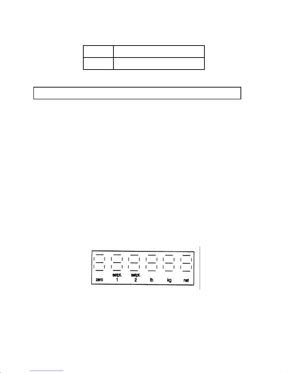
2.9 DIGITAL DISPLAY
The display is a green-blue vacuum fluorescent type. It consists of six 0.5” seven-segment digits with
lighted decimal point. Six fluorescent indicators are located below the display to correspond to printed
legends on the display lens, as shown in Figure 1. The display update rate for analog and digital load
cells is 12 updates/second.
FIGURE 1
2.10 ENCLOSURE TYPE AND CLEANING
The 8510-2001 and the 8510-2011 are housed in aluminum panel mount NEMA 1 enclosures with a
stainless steel front plate. An additional aluminum enclosure can be mounted on the back to house the
Analog, BCD, or Setpoint options. The enclosure is designed to be periodically cleaned only with a
clean cloth dampened with a mild window type cleaner. DO NOT USE ANY TYPE OF INDUSTRIAL
SOLVENT OR CHEMICALS. DO NOT SPRAY CLEANER DIRECTLY ONTO THE UNIT. DO NOT HOSE
DOWN.
4
Page 10

2.11 ZERO
2.11.1 AUTO ZERO MAINTENANCE (AZM)
The range of zero maintenance is limited to ± 2% of scale capacity, with the center of the range
determined during calibration. Weight variations which occur at a rate of 0.2 increments per second or
slower will be compensated. AZM can be disabled in the setup mode.
2.11.2 PUSHBUTTON ZERO
A front panel pushbutton provides re-zeroing of the scale over a range of ± 2% of scale capacity. The
ZERO pushbutton must be depressed while the scale is in a no-motion condition and at gross zero.
Pushbutton zero can be disabled in the setup mode.
2.11.3. POWER UP ZERO
When power is first applied to the scale, zero is automatically captured provided the weight is within +
2% of scale capacity, and a no-motion condition exists.
2.11.4 ZERO INDICATOR
The zero increment is ± 0.,5 increment wide. The display’s “zero indicator” is ON whenever the weight is
within ± 0.25 increment of the center of the zero increment.
2.12 TARE
2.12.1 PUSHBUTTON TARE
The TARE pushbutton on the keyboard can be used to tare a weight on the scale platform if the scale is
in a no-motion condition. If the weight is then removed from the scale platform, the Net Weight will be
displayed as a negative value. The NET indicator will be illuminated whenever a tare weight exists in the
Net Storage Register. Pushbutton Tare can be disabled in the setup mode. If the tare operation results
in a six digit negative net weight, the display will alternate between the weight value and a blank display
with a minus sign.
2.12.2 REMOTE TARE
If enabled in setup mode, a remote tare command using ASCII input will tare the weight on the scale
platform, providing the scale is in a no-motion condition. A remote tare clear command from a host will
clear the tare value if the weight has settled to a no-motion condition. See Section 5.4 for details.
2.12.3 MANUAL AND AUTO CLEAR TARE
Tare can be cleared manually by use of the CLEAR pushbutton, or automatically if the weight has settled
to a no-motion condition at a weight greater than 10 increments and returned to less than 0.5 major
increments from zero gross weight.
5
Page 11

3. INSTALLATION
Follow the instructions in this section carefully to install and program the Model 8510. Make sure that all
requirements in the specifications Section 2 of this manual have been met and verified before
proceeding. If any problems are encountered when programming, refer to the Troubleshooting Section
of this manual (Section 8).
3.1 SET UP PROCEDURE
3.1.1 Examine the shipping carton for any signs of damage. IF DAMAGE IS FOUND, FILE A CLAIM WITH
THE CARRIER IMMEDIATELY.
3.1.2 Open the carton and continue the inspection, checking for damaged or missing parts. The carton
should contain the following:
1 - 8510 Digital Indicator
1 - P/N 13358900A Digital Load Cell Harness
1 - P/N 13401400A Template for Panel Mounting
1 - P/N 13401300A Gasket
1 - DB-9 Connector Kit for Load Cell Cable
1 - Technical Manual
3.1.3 CAUTION! THE TYPE OF SCALE BASE (ANALOG OR DIGITAL) MUST BE VERIFIED BEFORE
PROCEEDING. The 8510 is shipped with the analog load cell harness installed. If the scale base is the
standard analog type, install the supplied DB-9 connector to the load cell cable as described in Section
6.2 of this manual. The analog load cell scale base can then be connected to the Load Cell Port without
further modification to the 8510. A listing of recommended Toledo Analog Scale Bases can be found in
Section 2.4 of this manual.
CAUTION!
DO NOT CONNECT AN ANALOG SCALE BASE TO THE 8510 WITH THE DIGITAL LOAD CELL
ADAPTER HARNESS INSTALLED OR DAMAGE WILL RESULT. DO NOT CONNECT A DIGITAL
SCALE BASE TO THE 8510 WITH THE ANALOG LOAD CELL HARNESS INSTALLED OR
DAMAGE WILL RESULT.
If a digital load cell scale base will be used with the 8510, the internal analog load cell harness must be
removed and the digital load cell adapter harness, p/n 13358900A shipped with the 8510, must be
installed. A list of recommended Toledo Digital Load Cell Scale Builds can be installed. A list of
recommended Toledo Digital Load Cell Scale Builds can be found in Section 2.3 of this manual. Refer to
Section 3.2 for instructions on installing the digital load cell adapter harness, and Section 6.1 for
instructions on connecting the supplied DB-9 connector kit to the digital load cell scale base cable.
3.1.4 Install option kits at this time. Instructions for installing the Analog, BCD, or Setpoint Modules
can be found in Section 7 of this manual.
3.1.5 Set the internal jumpers listed in Section 3.4 for the application. Jumper W2 must be shorted to
enable access into the setup mode used to program the 8510.
3.1.6 If installing the 8510 in a panel mount, refer to Section 3.3.
3.1.7 Refer to section 3.5 to make sure all power requirements have been met before connecting the
8510 to the power source. Make sure the power matches the voltage listed on the equipment data
plate. Before connecting power make sure all external wiring and cables are connected.
6
Page 12
3.1.8 After all options are installed and all external wiring and cables are connected, the 8510 can be
connected to AC power. Refer to Section 3.6 for the Power Up Sequence. If problems are
encountered, refer to Section 8, Troubleshooting in this manual.
3.1.9 The 8510 is now ready for programming and calibration. Refer to Section 4 for programming and
calibration instructions.
3.2 DIGITAL LOAD CELL ADAPTER HARNESS INSTALLATION
If a digital load cell scale base is used with the model 8510, the analog load cell harness, p/n 13356700A,
must be removed and the internal digital load cell adapter harness, p/n 13358900A shipped with the
8510, must be installed prior to connecting the digital scale base.
CAUTION!
DO NOT CONNECT OR DISCONNECT A DIGITAL LOAD CELL TO THE 8510 WITH POWER ON
OR DAMAGE TO THE 8510 AND THE DIGITAL LOAD CELL MAY RESULT.
To install the 13358900A digital load cell adapter harness in the 8510:
3.2.1 Disconnect power to the 8510 Indicator.
WARNING!
DISCONNECT ALL POWER TO THIS UNIT BEFORE REMOVING THE FUSE
OR SERVICING.
3.2.2 Remove the four nuts holding the back enclosure to the front plate assembly. Set the nuts aside
for later use. Separate the back enclosure from the front plate assembly.
3.2.3 Disconnect the printer harness at J3, the analog load cell harness at J4, and the power cord at J5
on the Power Supply PCB. Remove the analog load cell harness DB-9 connector mounted on the
rear cover.
3.2.4 Install the DB-9 connector on the new 13358900A digital load adapter harness in the hole in the
8510 rear cover where the analog load cell harness was located. Use the existing screwlock kit to
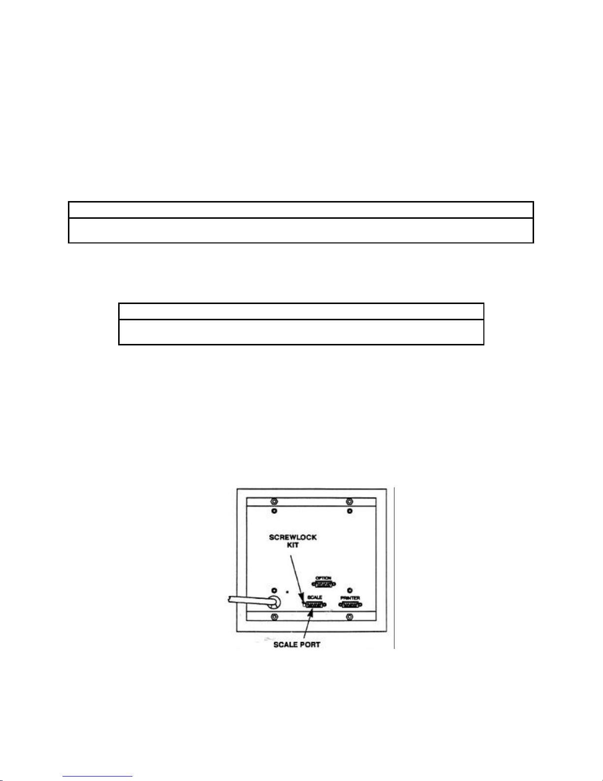
secure the connector. (See Figure 2)
FIGURE 2
7
Page 13
3.2.5 Connect the dual-5 connector from the 13358900A digital load cell adapter harness to J2 on the
OPEN
6.75
7.25
7.75
7.62
6.62
6.00
Power Supply PCB. The connector is keyed at pin 3. (Refer to Figure 6 for connector locations).
3.2.6 Reconnect the printer harness to J3 on the Power Supply PCB. Reconnect the power cord to J5
on the Power Supply PCB.
3.2.7 Reassemble the back cover to the front cover plate assembly using the four nuts removed in Step
2.
3.2.8 Refer to Section 6.1 to connect the digital load base to the model 8510 digital load cell port.
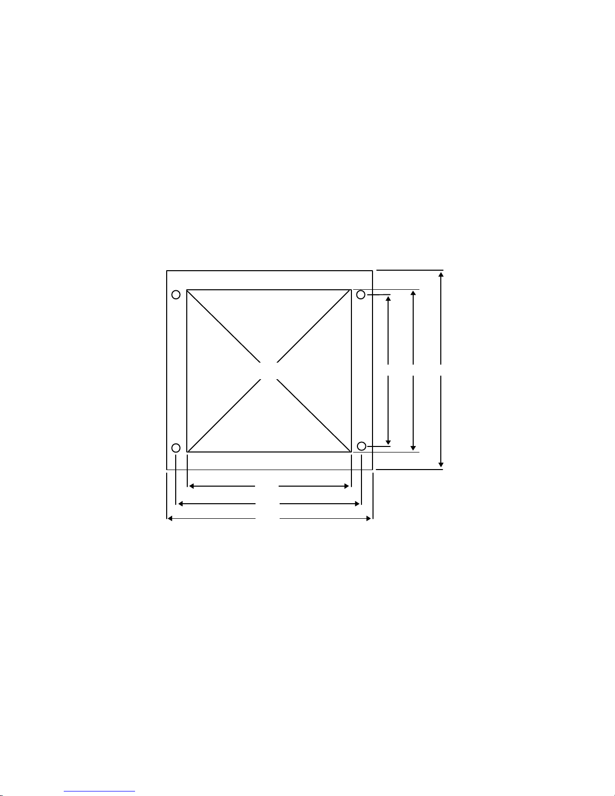
3.3 PANEL INSTALLATION
The models 8510-2001 and 8510-2011 are designed for panel mounting applications. The 8510 can be
mounted in a 6.75” x 6.62” cutout in a panel. To install the 8510 directly in a panel, use the template
shipped with the unit as a guide for the cutout and holes necessary to mount the 8510. The dimensions
for the cutout and mounting holes and minimum clearance required are listed below in Figure 3 and
Figure 4.
FIGURE 3
REQUIRED MINIMUM CLEARANCE
FOR PANEL MOUNTING
(8510-20XX SIDE VIEW)
8
Page 14
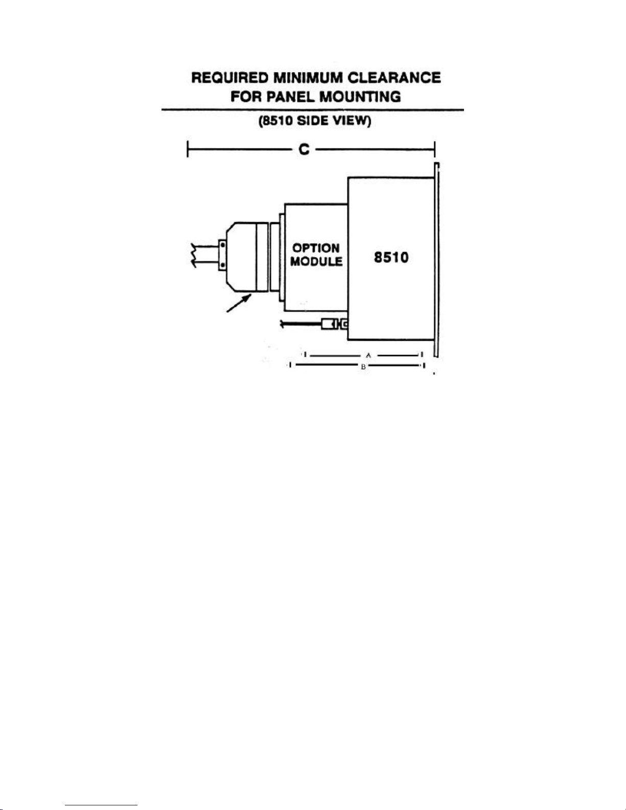
BCD Connector
A = 6” MIMIMUM CLEARANCE REQUIRED FOR 8510 W/O OPTION MODULE
B = 7” MINIMUM CLEARANCE REQUIRED FOR 8510 WITH SETPOINT MODULE OR ANALOG MODULE
C = 9” MINIMUM CLEARANCE REQUIRED FOR 8510 WITH BCD MODULE AND CONNECTOR
FIGURE 4
9
Page 15
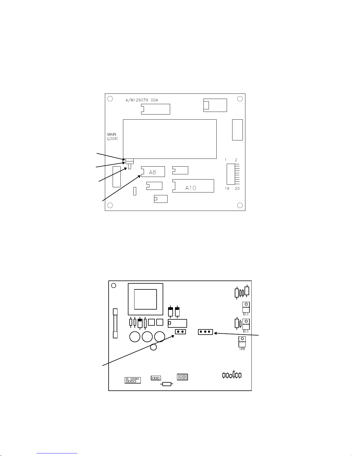
3.4 JUMPER DESCRIPTIONS
A1
2mV/V 3mV/V
CALIBJ4J3
3.4.1 The jumpers on the Main Logic PCB are as follows: (Refer to Figure 5)
W1 - Open = Display Decimal Point
Shorted = Display Metric Comma
W2 - Pins 1 & 2 Shorted = 256K EPROM in use (normal position).
Pins 2 & 3 Shorted = 512K EPROM in use
W3- Shorted = Normal Position
Open = Factory Use Only
W1
W2
W3
EPROM A8
FIGURE 5
3.4.2 The jumpers on the Power Supply PCB are as follows: (Refer to Figure 6)
W1 - 2 mv/v or 3 mv/v load cell select
W2 - Open = Disable entry into Setup Mode
Shorted = Enable entry into Setup Mode by pressing the ZERO and PRINT
pushbuttons simultaneously.
POWER SUPPLY PCB
W1W2
W2
W1
DLC
FIGURE 6
10
Page 16

3.5 POWER REQUIREMENTS
WARNING!
FOR CONTINUED PROTECTION AGAINST SHOCK HAZARD, CONNECT TO
A PROPERLY GROUNDED OUTLET. DO NOT REMOVE THE GROUND
PRONG.
The 8510 requires a properly grounded dedicated AC power line which must not be shared with other
types of electrical equipment which may generate “noise spikes” or “power surges”. The equipment
ground prong on the power cord must not be removed or bypassed using an adapter plug.
No AC voltage should exist between the Neutral and Ground lines. Voltage readings (between Neutral
and Ground) above 0.1 VAC indicate a problem with the ground line, and should be corrected before
connecting the 8510 to the line.
The supplied AC voltage to the 8510 must be within tolerances shown on the chart in Section 2.1, and
transient free. An isolation/regulation type transformer for electronic equipment may be required if these
types of problem conditions exist, and cannot be corrected at the source.
3.6 POWER UP SEQUENCE
On power up, the 8510 will display the following:
[888888] - All segments will momentarily illuminate.
[129123] - The Software Part Number will briefly display.
[L RR] - The Revision Level (RR) of the Software will briefly display. Example: L05 = “E” revision
software)
[xxxxxx] - The weight (x) will display next (or zero). If the Setpoint Option is enabled (F11), when the
weight or zero is displayed, the setpoint outputs will immediately turn ON if below SP1/SP2
target values or zero tolerance (SP3) will turn ON if within the preset tolerance from zero. If
the Analog Output is installed, the outputs will increase to maximum and the switched
output will open. If F4 is set to 1, 2, or 3, zero will be captured on power-up if the weight is
within ± 2% of scale capacity.
11
Page 17

4. PROGRAMMING AND CALIBRATION
4.1 ACCESSING PROGRAMMING/CALIBRATION MODE
To access the Programming/Calibration mode, jumper “W2” on the power Supply PCB (Refer to Figure
6) must first be installed on the two pins at location W2. Jumper W2 may be left on permanently, or
removed to prevent unauthorized entry into the setup mode after initial installation. When W2 is
installed, press and hold the PRINT key, then press the ZERO key to enter the Programming/Calibration
mode.
4.2 KEYBOARD FUNCTIONS
The functions of the keyboard in Normal Mode and Program Mode are as follows:
KEY FUNCTION MODE
Normal Mode:
ZERO
Program Mode:
Pressing this key will return the indicator to a gross
zero condition. (per section 2.11)
Used as a cursor key to backup to the previous
softswitch or to increment the active digit by one.
SELECT
SETPT.
TARE Normal Mode:
CLEAR Normal Mode:
PRINT Normal Mode:
Normal Mode:
Program Mode:
Program Mode:
Program Mode:
Used to select setpoints when the optional setpoint kit
is enabled. (f11)
Toggles fast/slow mode in f11.5, etc.
Used to tare the applied weight on the scale platform
(per section 2.12)
Used to change the status of the soft switch (on/off) or
to toggle through a selection of softswitch options.
When variable data is required, the tare key selects the
active (blinking) digit. At softswitch f11.4 tare is used
to bypass preact entry and advance to f12
USED TO CLEAR DISPLAYED TARE weight.
Advance to end of setup mode (cal off) or zero the
display and start over. At softswitch f11.3 when sp1 is
displayed, pressing clear will bypass setpoint entry and
advance to f11.4.
Used to initiate data transfer through the serial port to
host or printer.
Program Mode:
Advance to next softswitch and accept the displayed
data or softswitch status.
12
Page 18

4.3 QUICK REFERENCE CHART FOR SOFTSWITCHES
Following is a quick reference chart for the Model 8510 softswitches in program mode. The softswitch
number (SSW#) will be listed first followed by the initial default setting at power up.
(Example: [F0 X] where F0 = SSW#, and X = default setting)
SSW#/DEFAULT DESCRIPTION
[F0 0] SPAN ADJUST
[F1 0] ZERO ADJUST
[F2 0] LOAD CELL TYPE
[F3 1] CALIBRATION UNITS LB OR KG (LB = 1)
[F4 1] AUTOZERO MAINTENANCE (1 = 0.5d)
[F5 0] PUSHBUTTON ZERO ENABLE
[F6 0] MOTION SENSITIVITY
[F7 0] FILTER SENSITIVITY (0 = OFF)
[F7.1 0] DigiTOL® LOAD CELL FILTER
[F8 0] EXPANDED DISPLAY
[F9 1] TARE ACTIVE
[F10 0] AUTO TARE CLEAR
[F11 0] SETPOINT OPTION SELECT
[F11.1 0] SETPOINT ZERO TOLERANCE RANGE
[F11.2 0] BCD MOTION SYNC
[F11.3 0] SETPOINT VALUE ENTRY IN SETUP ONLY
[F11.4 0] SELECT PREACT VALUES
[F11.5 0] ANALOG OUTPUT TRIMMING
[F11.6 0] CALIBRATION OF ANALOG OUTPUT
[F11.7 0] ANALOG ZERO CALIBRATION WITH TEST WEIGHTS
[F11.8 0] ANALOG ZERO CALIBRATION VIA KEYBOARD
[F11.9 0] ANALOG SPAN CALIBRATION WITH TEST WEIGHTS
[F11.E 0] ANALOG SPAN CALIBRATION VIA KEYBOARD
[F12 0] PRINTER OUTPUT SETPUP CONTINUOUS OR DEMAND
[F12.1 1] CONTINUOUS OR DEMAND OUTPUT (1 = DEMAND)
[F12.2 ] BAUD RATE [9600 ]
[F12.3 2] PARITY SELECT (2 = EVEN)
[F12.4 0] STX/CHECKSUM SELECT
[F12.5 0] DATA FORMAT (0 = DISPLAYED WGT ONLY) EXPANDED PRINT ENABLE
[F12.6 0] EXPANDED PRINT ENABLE
[F12.7 0] AUTOPPRINT AT SP1
[F12.8 0] AUTOPRINT AT SP2
[F13 0] ENABLE REMOTE COMMAND INPUTS
[F14 0] LOAD CELL QUANTITY/SHIFT ADJUST
[F15 0] DISPLAY INDIVIDUAL CELL OUTPUT
[F19 0] ZERO CURSOR ENABLE
[F99 0] RESET TO FACTORY DEFAULTS
[CAL 0] CALIBRATION MODE
NOTE: THE LEVEL L05 OR HIGHER SOFTWARE (“E” OR HIGHER REVISION EPROM 12912300A)
AUTOMATICALLY DETECTS OPTION HARDWARE INSTALLED AND WILL DISPLAY ONLY VALID
SOFTSWITCHES.
13
Page 19

4.4 PROGRAMMING AND CALIBRATION MODE
SSW #/PROMPT DESCRIPTION
[F0 ] CALIBRATION ADJUST FEATURE
NOTE: TEST WEIGHTS MUST BE ON THE SCALE BEFORE ENTERING THIS STEP CALIBRATION
ADJUST IS A FINE ADJUSTMENT FEATURE TO BE USSED ONLY AFTER FULL CALIBRATION.
0 = Bypass OD and Go to SSW F1
[000000]
1 = Start span calibration adjustment. First place test weight on platform. Display
will show [000000] with the MSD (most significant digit) active (blinking). (If
PRINT is pressed with display showing [000000], the procedure is aborted).
Enter the value of the test weight.
- Press ZERO to increment the active digit by one
- Press TARE to move to the next lower MSD
- Press PRINT to accept displayed value and go to F1
- Press CLEAR to zero the display and start over
[F1 ] ZERO ADJUST
0 = Bypass SSW and go to F@
1 = Enter current initial weight on scale as zero. Display will count down from 15 while setting
the new initial. Scale motion will cause countdown to restart from 15.
- Press PRINT to start procedure
- Press CLEAR during countdown to abort procedure
[F2 ] LOAD CELL TYPE
0 = Analog load cell(s)
1 = Digital load cell/Power Module
[F3 ] CALIBRATION UNITS
1 = Pounds
0 = Kilograms
14
Page 20

[F4 ] AUTOZERO MAINTENANCE (AZM, REFER TO SECTION 2.11)
AZM is a feature that maintains the displayed zero in the center of the zero increment. This step
selects the size of the window over which zero change is compensated for at the rate of 0.2
increments per second. If the weight exceeds the AZM window, then AZM is disabled. As long as
the weight is within the AZM window selected, the 8510 will remove 0.2 increments of the zero
change per second. AZM will correct for zero drift up to a maximum of ±4% of scale capacity, with
the center of the zero range determined during calibration.
Normal AZM is disabled when the 8510 is in the net weight mode. Selection 4 permits AZM to
operate in the net weight mode as well as in the gross mode when the weight on the scale is
within 3 increments of gross zero. When AZM is enabled, zero is captured at power-up if the
weight on the scale is within ±2% of scale capacity of gross zero.
Selection AZM Window Legal-For-Trade Application
0 AZM Disabled Not Applicable
1 ± 0.5 Increment (Gross Mode Only) Animal, Food, & Retail Scale
2 ± 1 increment (Gross Mode Only) All other Industrial Scales
3 ± 3 Increment (Gross Mode Only) Vehicle Scales
4 ± 3 Increment (Gross Mode Only) Not Applicable
[F5 ] PUSHBUTTON ZERO
0 = Pushbutton Zero Disabled
1 = ± 2 of Scale Capacity
2 = ± 20 of Scale Capacity
[F6 ] MOTION SENSITIVITY
The 8510 includes a weight in motion detector which requires three successive weight readings
within the selected range of either 1.0 or 3.0 increments for a “no-motion” signal. The motion
detector signal inhibits pushbutton or remote ZERO, TARE, and PRINT.
0 = Disable Motion Detector
1 = 1.0 increment sensitivity
2 = 3.0 increment sensitivity
[F7 ] FILTER SENSITIVITY
The 8510 has a low pass multi-pole digital filter that is selectable for various environmental
conditions. The display update rate is slowed slightly when more filtering is selected. By
selecting higher filter rates, more movement or vibrations to the scale platform can be filtered out.
0 = No added filtering (Least)
1 = Light filtering
2 = Medium filtering
3 = Heavy filtering
15
Page 21

[F7.1 ] DigiTOL® LOAD CELL FILTER
DigiTOL® load cell bases provide a built-in digital filter that can interfere with slow speed filling or
batching operation. This filter MUST be disabled for setpoint applications. This step is only
displayed if the 8510 is configured for DigiTOL® load cell base.
0 = DigiTOL® Load Cell Filter Disabled
1 = DigiTOL® Load Cell Filter Enabled (default)
[F8 ] EXPANDED DISPLAY
This feature will allow the 8510 to display minor increments (0.1 d) on the display. This feature is
used for test purposes only. Operate in the normal display mode only.
0 = Normal display mode
1 = Minor increments are displayed
[F9 ] TARE MODE
When auto-tare is selected, a tare is taken whenever the 8510 is in the gross weight mode and the
scale settles on a weight greater than 5 increments above gross zero.
0 = Tare disabled. Advance to F11
1 = Pushbutton Tare mode only. Advance to F10
2 = Auto-Tare mode only
[F10 ] AUTO CLEAR TARE
When enabled, Auto Clear Tare will automatically clear the entered tare value if the weight has
settled to a no-motion condition at a weight greater than 10 d increments and then returned to less
than 0.5 d increments from gross zero.
0 = Disable Auto Clear Tare
1 = Enable Auto Clear Tare. Tare will clear with return to gross zero
NOTE: THE LEVEL L05 (“E” OR HIGHER REVISION SOFTWARE) AUTOMATICALLY DETECTS ANY
INSTALLED OPTION MODULES. IF THE SETPOINT HARDWARE IS CONNECTED, F11.1 WILL BE
THE NEXT PROMPT. IF BCD HARDWARE IS CONNECTED, F11.2 WILL BE THE NEXT PROMPT. IF
ANALOG HARDWARE IS CONNECTED, F11.5 WILL BE THE NEXT PROMPT. IF NO HARDWARE IS
ATTACHED, F11 WILL E THE NEXT PROMPT. ONLY VALID SELECTIONS ARE DISPLAYED.
[F11 ] SETPOINT OPTION SELECT (no hardware attached)
0 = Setpoint option not enabled. Proceed to F12
1 = Setpoint Option enabled. Proceed to F11.1
[F11.1 ] SELECT ZERO TOLERANCE RANGE
Zero tolerance range provides ability to select a bandwidth in which Setpoint SP3 is turned on.
0 = 0 Increments (SP3 output off)
1 = 1 d Increment
5 = 5 d Increments
- Press TARE to display selections
- Press PRINT to enter selection and advance to F11.3
16
Page 22

[F11.2 ] SELECT BCD MOTION SYNC (Displayed only when BCD is installed)
0 = BCD and status lines active all the time
1 = BCD and status lines Over, Under, and Net, updated only during no-motion conditions.
Motion line is inactive.
- Press TARE to toggle selection
- Press PRINT to enter selection and advance to F12
[F11.3 ] SELECT SETPOINT ENTRY ONLY FROM SETUP
0 = Setpoint values can be entered or changed using the “Select Setpt.” pushbutton on the 8510
front panel during normal operation. Proceed to F11.4.
1 = Setpoint values can be recalled for display only using the “Select Setpt.” pushbutton. The
setpoint values must be entered or changed in the setup mode using the following steps:
[SP1 ] SETPOINT 1
Press PRINT to advance to CURRENT SETPOINT 1 VALUE
- Press CLEAR to advance to [F11.4]
- Press ZERO to back up to [F11.3].
[XXXXXX] CURRENT SETPOINT 1 VALUE
Display now shows previous setpoint 1 value (x).
- Press ZERO to back up [SP1]
- Press PRINT to accept displayed value and go to [SP2]
- Press CLEAR to zero display before entering a new value
[E20 ] ERROR 20
May display when an incorrect entry is made. Indicates existing Preact value is greater than
setpoint value. Clear setpoint value, then re-enter SP1 value. (E20 will display for 2 seconds, then
SP1 prompt will display again). Refer to [F11.4].
[000000] ENTER NEW SETPOINT 1 VALUE
When CLEAR is pressed, the display will show zeros with the MSD as the active digit.
- Press TARE to move to the next decade position
- Press ZERO to increment active digit by one
- Press PRINT to accept displayed value and advance to SP2
- Press CLEAR to zero display and start over
17
Page 23

[SP2 ] SETPOINT 2
- Press PRINT to advance to CURRENT SETPOINT2 VALUE
- Press CLEAR to advance to [F11.4]
- Press ZERO to back up to [SP1]
[XXXXXX] CURRENT SETPOINT 2 VALUE
The display will show the previous Setpoint 2 value (x).
- Press ZERO to back up to [SP1 ]
- Press PRINT to accept value and go to [F11.4]
- Press CLEAR to zero display and enter new value
[000000] ENTER NEW SETPOINT 2 VALUE
When CLEAR is pressed the display will show zeros with the MSD as the active digit.
- Press TARE to move to the next decade position
- Press ZERO to increment active digit by one
- Press CLEAR to zero display and start over
- Press PRINT to accept the displayed value and proceed to [F11.4]
E20 ] ERROR 20
May display when an incorrect entry is made. Indicates existing Preact value is greater than
setpoint value. Clear setpoint value, then re-enter SP1 value. (E20 will display for 2 seconds, then
SP1 prompt will display again.) Refer to [F11.4].
[F11.4 ] SELECT PREACT VALUES
Preact Values are used to adjust the corresponding setpoint values as follows:
Setpoint = Setpoint value - Preact Value.
- Press TARE to bypass preact entry and advance to [F12]
- Press PRINT to enter or recall/modify preact values
[P1 ] ENTER/RECALL PREACT FOR SETPOINT 1
- Press CLEAR to advance to end of setup
- Press PRINT to advance to CURRENT PREACT VALUE FOR SETPOINT 1
[XXXXXX] CURRENT PREACT VALUE FOR SETPOINT 1
- Press ZERO to back up to [P1]
- Press PRINT to accept entry and go to [P2]
- Press CLEAR to zero display before entering a new value
18
Page 24

[000000] ENTER NEW PREACT VALUE FOR SETPOINT 1
Display now shows zeros with the MSD as the active (blinking) digit.
- Press ZERO to increment active digit by one
- Press TARE to move to the next LSD
- Press PRINT to accept displayed value and advance toP2. (E20 = preact value is greater than
the value entered for setpoint).
- Press CLEAR to zero display and start over
[P2 ] ENTER/RECALL PREACT FOR SETPOINT 2
- Press CLEAR to advance to end of setup
- Press PRINT to advance to CURRENT PREACT VALUE FOR SETPOINT 2
- Press ZERO to back up to [P1]
[XXXXXX] CURRENT PREACT VALUE FOR SETPOINT 2
Display now shows previous preact entry or zeros.
- Press ZERO to back up to [P2]
- Press PRINT to accept entry and go to [F12]
- Press CLEAR to zero display before entering a new value
[000000] ENTER NEW PREACT VALUE FOR SETPOINT 2
Display now shows zeros with the MSD as the active (blinking) digit.
- Press ZERO to increment active digit by one
- Press TARE to move to the next LSD
- Press PRINT to accept displayed value and go to F12. (E20 = preact value is greater than the
value entered for setpoint.) Prompt will advance to F12
- Press CLEAR to zero display and start over
[F11.5 ] ANALOG OUTPUT TRIMMING
This step allows trimming of the analog output to fine tune the remote device. Limitations are ±
3% of full scale for zero adjustment and ± 8% for span adjustment.
0 = Bypass F11.5 and advance to F11.6
1 = Start analog trimming as follows:
- Press CLEAR to abort and advance to [CALOFF]
- Press ZERO to step back to F9 or F10 depending on F9 Tare active or disabled
- Press TARE to toggle selection
- Press PRINT to accept displayed selection
19
Page 25

[0 FAS] Fast Mode zero reading analog output adjustment
[0 SLO] Slow Mode zero reading analog output adjustment
Alters zero reading analog output at a fast (FAS) or slow (SLO) rate. To increase the analog
reading at scale zero, press the TARE key, or to decrease, press the ZERO key. (Change is one
“click” per key press.) Press SELECT SETPOINT key to toggle between Fast Mode and Slow Mode
rate of adjustment.
- Press SELECT SETPOINT key to toggle between FastMode (FAS) and Slow Mode (SLO) rate
of adjustment
- Press TARE to increase analog output
- Press ZERO to decrease analog output
- Press CLEAR to abort adjustment and advance to [CALOFF]
- Press PRINT to accept displayed value and advance to span adjustment
[S FAS] Fast Mode span reading analog output adjustment
[S SLO] Slow Mode span reading analog output adjustment
Alters span reading at a fast (FAS) or slow (SLO) rate. To increase the analog reading at full scale,
press the TARE key, or to decrease, press the ZERO key. (Change is one “click” per keypress.)
Press SELECT SETPOINT key to toggle between Fast and Slow Mode rate of adjustment.
NOTE: During this adjustment, the analog output will output voltage or current equal to full
capacity of the scale. The display will not show weight, however, the analog output will reflect full
scale output.
- Press SELECT SETPOINT key to toggle between Fast (FAS) and Slow Mode (SLO)
- Press TARE to increase analog output
- Press ZERO to decrease analog output
- Press CLEAR to abort adjustment and advance to [CALOFF]
- Press ZERO to return to F11.5 and start over
- Press PRINT to accept displayed value and advance to F11.6
[F11.6 ] CALIBRATION OF ANALOG OUTPUT
0 = No offset or span adjustments are applied to calibrated scale zero or full scale readings.
Zero and full scale analog output coincides with scale zero and full scale digital display.
F11.7, F11.8, F11.9, and F11.E will be bypassed.
1 = Adjustment of zero and span is made using calibration constants. Zero and full analog
output may not coincide with zero and full scale digital display. The span must be a
minimum of 1000 divisions of displayed weight. Failure to meet the minimum will result in
an error message [E 32]. The prompt will then advance to F11.7
[F11.7 ] ANALOG ZERO CALIBRATION WITH TEST WEIGHTS
0 = Bypass F11.7 and advance to F11.8
1 = Initiate zero calibration as follows:
- Press CLEAR to abort setup and advance to [CALOFF]
- Press ZERO to backup to F11.6
- Press TARE to toggle selection
- Press PRINT to accept displayed selection
[0 Ld ] Press PRINT to acknowledge additional “dead load” at zero is on scale platform
20
Page 26

[15 CAL] Display will count down from 15 while zero reading is taken. After reading is taken,
advance to F11.9. SPAN CALIBRATION MUST BE PERFORMED AFTER ZERO
CALIBRATION.
[F11.8 ] ANALOG ZERO CALIBRATION VIA KEYBOARD
0 = Bypass F11.8 and advance to F11.9
1 = Initiate keyboard adjustment of analog zero as follows:
- Press CLEAR to abort setup and advance to [CALOFF]
- Press ZERO to backup to F11.7
- Press TARE to toggle selection
- Press PRINT to accept displayed selection
[XXXXXX] ZERO OFFSET VALUE
Display now shows previous weight offset value.
- Press PRINT to accept displayed value and advance to F11.9.
- Press CLEAR to zero display and to enter new value. Advance to ENTER NEEW ZERO
OFFSET VALUE
[X00000] ENTER NEW ZERO OFFSET VALUE
CLEAR was pressed, and display now shows zeros with the MSD (most significant digit) blinking.
(X = blinking MSD).
- Press ZERO to increment blinking digit by one
- Press TARE to move to the next least MSD (one position to the right)
- Press PRINT to accept displayed value and advance to F11.9
- Press CLEAR TO ZERO display and start over
[F11.9 ] ANALOG SPAN CALIBRATION WITH TEST WEIGHTS
0 = Bypass F11.9 and advance to F11.E
1 = Start Span Calibration with Test Weights. Scale must be at zero reference point to begin
span calibration
- Press CLEAR to abort setup and advance to [CALOFF]
- Press ZERO to backup to F11.9
- Press TARE to toggle selection (0 = Off, 1 = ON).
- Press PRINT to accept displayed selection
[15 CAL] Display will count down to 0 while weight reading for span is determined. Count will
restart at 15 if vibration is detected.
[Add Ld] Place load equal to desired FULL ANALOG OUTPUT WEIGHT (at least 1000 divisions
of calibrated scale) on scale platform.
- Press CLEAR to abort and advance to CALOFF
- Press ZERO to return to F11.9 and start over
- Press PRINT to continue
21
Page 27

[15 CAL] Display will count down to 0 while span reading is determined. If no errors occur, the
prompt then advances to F12. If a weight representing less than 1000 d is used, error
[E 32] is displayed and the previous span calibration is retained. To clear the error:
- Press ZERO to backup to F11.9 and start over
- Press CLEAR to abort setup and advance to [CALOFF]
- Press PRINT to start over at F11.9
[F11.E ] ANALOG SPAN CALIBRATION VIA KEYBOARD
0 = Bypass F11.E and advance to F12.
1 = Start span calibration via keyboard
- Press CLEAR to abort setup and advance to [CALOFF]
- Press ZERO to backup to F11.E
- Press TARE to toggle selection
- Press PRINT to accept displayed selection
[XXXXXX] SPAN OFFSET VALUE
Display now shows previous weight stored as the span offset value.
- Press ZERO to backup to F11.E
- Press PRINT to accept value and advance to F12
- Press CLEAR to zero display and enter new value. Advance to ENTER NEW SPAN OFFSET
VALUE
[X00000] ENTER NEW SPAN OFFSET VALUE
CLEAR was pressed, and display now shows zeros with the MSD (most significant digit) blinking.
(X = blinking digit). Enter the weight value to use as the new span offset.
- Press ZERO to increment blinking digit by one
- Press TARE to move to the next least significant digit (one position to the right)
- Press PRINT to accept value and advance to F12
- Press CLEAR to zero display and start over
If a weight representing less than 1000 d is entered error (E32] is displayed and the previous span
calibration is retained. To clear the error:
- Press ZERO to backup to F11.E and start over
- Press CLEAR to abort setup and advance to [CALOFF]
- Press PRINT to start over at F11.E
[F12 ] PRINTER OUTPUT SETUP
Press TARE to bypass printer setup and advance to calibration. Press PRINT to continue with
F12.1.
[F12.1 ] SERIAL DATA OUT
0 = Continuous Output Mode
1 = Demand Output Mode
22
Page 28

[F12.2 ] BAUD RATE
[XXXX ]
Previously selected baud rate (XXXX) will be displayed. Press TARE to display the next baud rate,
and PRINT to enter selection and advance to F12.3. Valid selections are:
- Demand Mode: 300, 1200, 2400, 4800, or 9600 baud
- Continuous Mode: 4800, or 9600
[F12.3 ] PARITY
0 = Parity always “0” (space)
1 = Odd parity
2 = Even parity
[F12. 4 ] STX/CHECKSUM
Checksum is defined as the 2’s complement of the 7 low order bits of the binary sum of all
characters proceeding the checksum, including STX (start of text) and CR (carriage return). Bit 8
of the checksum character is the parity bit of the 7 low order bits of checksum. This character is
used as a means to verify transmitted data. The receiving device must be capable of computing
and comparing a checksum also.
0 = No STX or Checksum sent
1 = STX will be sent as the first character of data. Checksum character will be transmitted after
the carriage return (CR) character in the data output.
NOTE: STX/CHECKSUM MUST BE ENABLED FOR OPERATION WITH THE METTLER
TOLEDO MODEL 8860 PRINTER
NOTE: IF CONTINUOUS MODE IS SELECTED F12.5 AND 12.6 WILL NOT DISPLAY.
[F12.5 ] DATA FORMAT (DEMAND MODE ONLY)
0 = Single line, displayed weight only
1 = Single line, gross, tare, and net
2 = Multiple line, gross, tare and net
[F12.6 ] EXPANDED PRINT (DEMAND MODE ONLY)
0 = Normal print
1 = Expanded print. The gross or net weight will be proceeded by the control character “SO”
(shift out) to indicate to the receiving device that this weight field is to be printed larger than
the previous data if the receiving device is capable of doing so. The control character “SI”
will then follow after the field to shift the device back to normal print mode.
NOTE: IF THE SETPOINT OPTION IS NOT SELECTED, SSW F12.7 AND F12.8 WILL BE BYPASSED.
[F12.7 ] AUTO PRINT AT SETPOINT 1
0 = Disable auto print at setpoint 1
1 = Auto print at setpoint 1 after returning from zero
23
Page 29

[F12.8 ] AUTO PRINT AT SETPOINT 2
0 = Disable auto print at setpoint 2
1 = Auto print at setpoint 2 after returning from zero
[F13 ] ENABLE REMOTE COMMANDS
0 = Remote ASCII input is disabled. Characters will be ignored
1 = Remote ASCII input characters will duplicate the keyboard functions: PRINT, TARE, ZERO,
and CLEAR. (Refer to Section 5.4).
[F14 ] LOAD CELL QUANTITY/SHIFT ADJUST (DigiTOL ® Power Module Only)
This selection allows the number of load cells connected to the DigiTOL ® Power Module to be
entered and shift adjustment to be performed on each cell. The shift adjustment allows
compensation for differences in output from each of the load cells used with the model 2157 Floor
Scale. the model 2157 uses four load cells. This step must be performed before calibrating the
Power Module/2157.
0 = Bypass step F14 and advance to F15
1 = Select quantity of load cells and perform shift adjustment
[X LCS] SELECT NUMBER OF LOAD CELLS (DigiTOL ® Power Module Only)
This prompt indicates the previously stored load cell quantity (X). After selecting the number of
cells, the 8510 will enter shift compensation mode.
- Press TARE to toggle between 2, 3, or 4 load cells
- Press PRINT to accept displayed value
[E SCL] EMPTY SCALE
Empty the scale platform, then press the PRINT key. The indicator will count down from 15 to 0
while zero reference is checked. Any change from motion to no-motion will cause the count to
reset each time to 15 before starting over. If the count is continually reset or if any errors are
displayed, refer to the troubleshooting section.
[CELL 1] ADD LOAD TO CELL #1
This step will shift adjust load cell #1. First place a test weight above cell #1. The weight does not
have to be a specific amount, although the greater the weight used, the more accurate the shift
compensation will be. After placing the weight above the cell, press PRINT to start the shift
adjustment on cell #1. The display will count down from 15 to 0 while the adjustment value is
calculated. When complete, the prompt for the second load cell [CELL2] will display. Perform the
same procedure for the remaining cells. When the last cell has been shift adjusted, the prompt will
advance to F15.
24
Page 30

Load Cell #1 is the cell to the right of the J-Box (viewed from the top of the deck) as shown in the
following diagram. Cells 2, 3, and 4 are located clockwise from cell #1.
Cell #2
Cell #4
2157 Base
J-Box
Cell #1
Cell #3
[F15 ] DISPLAY INDIVIDUAL CELL OUTPUT (DigiTOL ® Power Module Only)
This step allows the display of raw count output for each load cell connected to a DigiTOL ®
Power Module or Model 2157 floor scale. Verification of the initial load cell raw count output is
necessary to determine that each load cell is carrying an even share of the load. Before
performing this test, the scale base must be level and must not rock. The procedure for correcting
these conditions is found in the scale base technical manual. All load cells must be within 1000
counts of each other. If required shim the base to obtain this reading. Refer to the scale base
technical manual for shimming instructions.
NOTE: When the DigiTOL ® Power Module is used to convert a vessel such as a tank or hopper
into a scale, the load cells may not receive even loading due to the construction of the vessel.
This variance may be reflected in uneven initial raw count outputs that cannot be shimmed out.
- Press TARE to toggle between load cells
- Press CLEAR to quit and advance to [CAL]
[F16 ] ZERO CURSOR
The zero cursor is used in one of two modes controlled by setpoint operation. If setpoints are
disabled [F11 0], then the zero cursor is illuminated when the wei8ght on the scale is within the
±0.25 increments of zero. If setpoints are enabled [F11 1], then the zero cursor is illuminated when
the weight on the scale is within the zero tolerance of gross or net zero.
0 = Zero Cursor Disabled
1 = Zero Cursor Enabled
[F99 ] RESET TO DEFAULT SELECTIONS
0 = Skip resetting to default settings and advance to calibration
1 = Advance to [LOAd 0] and load default settings
25
Page 31

[LOAd 0 ] RESET TO FACTORY DEFAULTS
- Press Tare key to change displayed selection to a 1
0 = Skip resetting to default settings and advance to calibration
1 = Reset to factory defaults as shown below:
Step Description Default Step Description Default
F0 Span Adjust N/A F11.5 Analog Output Trimming N/A
F1 Zero Adjust N/A F11.6 Analog Output Limited Range 0
F2 Load Cell Type N/A F11.8 Analog Output Zero Zero
F3 Calibration Units N/A F11.9 Analog Output Capacity Capacity
F4 Auto Zero Maintenance 1 F12.1 Data Output Mode 1
F5 Pushbutton Zero Enable 1 F12.2 Baud Rate 9600
F6 Motion Sensitivity 1 F12.3 Parity 2
F7 Filter 0 F12.4 STX/Checksum 0
F7.1 DigiTOL® Load Cell Filter 0 F12.5 Weight Data Format 0
F8 Expanded Weight Display 0 F12.6 Expanded Weight Printing 0
F9 Tare Enable 1 F12.7 Autoprint at SP1 0
F10 Auto Clear Tare 0 F12.8 Autoprint at SP2 0
F11 Setpoint Enable 0 F13 Enable ASCII Input 0
F11.1 Zero Tolerance Range 0 F14 Load Cell Quantity N/A
F11.2 BCD Motion Sync Disable 0 F15 Display Load Cell Counts N/A
F11.3 Setpoint Data Entry Enable 0 F16 Zero Cursor Enable 1
F11.4 Preact Value Entry Enable 0 F99 Reset To Factory Defaults N/A
CAL Calibration N/A
[CAL ] SCALE CALIBRATION PROCEDURE
This step calibrates the scale base and must be performed when first installing the 8510 or after
performing a shift adjustment.
- Press PRINT to enable calibration mode
- Press CLEAR to bypass calibration and go to [CALOFF]
[C1 ] SCALE CAPACITY SELECT
[000100]
The display shows the previously stored capacity or defaults to the first legal value. Only valid
capacities may be selected. The value of which digit is incremented is limited to legal scale
capacities. Refer to valid capacity selection Table 1 in Section 2.3.
- Press ZERO to increment the blinking digit by one unit
- Press TARE to go to the next MSD
- Press CLEAR to zero display and start over
- Press PRINT to accept the displayed value
26
Page 32

[C2 ] INCREMENT SIZE
[ 00]
The previously programmed or default increment size is displayed. Only valid increment
selections will be displayed and selected.
- Press TARE to display the next valid increment size
- Press PRINT to accept the displayed increment size
[E SCL ] EMPTY SCALE PLATFORM
Empty the scale platform to set initial, then press PRINT to continue.
[15 CAL] SET INITIAL
The display will count down from 15 to 0 while initial is set, then advance automatically to [Add
Ld]. If any errors are displayed, refer to Section 8.2. If motion is detected in this mode, the count
will be reset to 15 and the initial adjustment will start over.
[Add Ld] ADD LOAD
Place the selected test weight on the scale platform, then press PRINT to continue.
[00000 ] ENTER LOAD
Enter the test weight value by entering digits from left to right. The digit that is blinking is the
active digit. No decimal value is permitted. The maximum test weight value is 105% of the full
scale capacity.
- Press TARE to move the active digit one position to the right
- Press ZERO to increment the active digit by one
- Press PRINT to enter the displayed value
[15 CAL] SET SPAN
The display will count down from 15 to 0 while span is set. (Note: If F2 = 1 (Digital Load Cell), the
display will show [CAL d] if calibration was successful and will not prompt again for empty scale.)
[E SCL] EMPTY SCALE
Empty the scale platform, then press PRINT to continue.
[15 CAL] RECHECK INITIAL
The display will count down from 15 to 0 while initial is rechecked.
[CAL d ] CALIBRATION DONE
This prompt is momentarily displayed when calibration was successful. If any error codes are
displayed, refer to Error Code Summary Section 8.
[CALOFF ] END OF SOFTSWITCHES
Press ZERO to return to the [CAL] prompt, or press ZERO and PRINT simultaneously to exit the
program mode. Press PRINT then ZERO while PRINT is still depressed.
27
Page 33

5. RS232 SERIAL INPUT/OUTPUT
5.1 SERIAL DATA OUTPUT IN DEMAND MODE
The model 8510 will transmit RS232C serial data when a print command is issued using the PRINT
pushbutton, Auto Print, or a remote print command from a host. The data format, baud rate, checksum,
parity, etc. are selectable in the setup mode. The serial data is output in an 10-bit ASCII frame which
includes: 1 start bit, 7 data bits, 1 parity bit, and 1 stop bit. Parity is selectable as zero, odd, or even
using SSW F12.3. STX/Checksum can be enabled or disabled using SSW F12.4. All demand mode
printing is inhibited during motion and when the weight is under gross zero. Printing is allowed on
power-up whether or not zero is captured if AZM is enabled (SSW F4). The available formats are as
follows:
5.1.1 SINGLE LINE DISPLAYED WEIGHT FORMAT
N
DATA SOX X X X X X X S
NOTES A B C D D D D D D F G G H I J K
NOTES
A - SO = Shift-Out character (optional). If SSW F12.6 = 1, expanded print is enabled if receiving device
is capable of using SO for enabling expanded (double-width) printing.
B - STX = Start of Text character (optional). If SSW F12.4 = 1, STX and checksum characters will be
sent in this position.
C - X = weight data digit, minus sign (-) for negative weight or tare, or space character will be sent in
this position.
D - X = Weight data digit or decimal point character.
E - SP = Space character.
F - LB sent for pounds when SSW F3 = 1. KG sent for kilograms when SSW F3 = 0.
G - Space character and NET will be sent if displayed weight is a net weight.
H - SI = Shift-In character. If SSW F12.6 = 1, SI will reset receiving device to normal print mode (if
receiving device is capable of using SO/SI to toggle between expanded and normal print modes.)
I - CR = carriage return character.
J - CHK = checksum character (optional). Checksum will be sent with STX if SSW F12.4 = 1.
K - LF = line feed character.
5.1.2 SINGLE LINE GROSS/TARE/NET FORMAT
L
P
BSP
ETS
I
C
C
HKL
R
F
DATA S
TX* X X X X X X SPLBSP* * X X X X X SPLBSPTRSPSO* X X X
Notes A B B B B B B B C D C E E E E E E E C D C F C G H H H H
NOTES
A - STX = Start of Text character (optional). If SSW F12.4 = 1, STX and checksum characters will be
sent in data string
N
X X X SPLBS
H H H C D C I J K L M
ETSIC
P
28
C
HKL
R
F
Page 34

B - Gross weight data field (7 characters). (* = digit, minus sign (-), or space, X = digit or decimal
point.)
C - SP = Space character
D - LB = pounds when SSW F3 = 1, KG = kilograms when SSW F3 = 0
E - Tare weight data field (7 characters). (* = digit, minus sign (-), or space, X = digit or decimal point
F - TR = characters for tare weight
G - SO = Shift-Out character (optional). If SSW F12.6 = 1, expanded print is enabled (if receiving device
is capable of using SO for enabling expanded (double-width) printing
H - Net weight data field (7 characters), (* = digit, minus sign (-), or space, X = digit or decimal point.)
I - NET = characters for net weight
J - SI = Shift-in character. If SSW F12.6 = 1, SI will reset receiving device to normal print mode (if
receiving device is capable of using SO/SI to toggle between expanded and normal print modes.)
K - CR = carriage return character
L - CHK = checksum character (optional). Checksum will be sent with STX if SSW F12.4 =1
M - LF = line feed character
5.1.3 THREE LINE GROSS/TARE/NET FORMAT
LINE 1
GROSS WEIGHT
Line
One
Data
S
TXX X X X X X X SPLBC
C
H
R
K
Notes A B B B B B B B C D E G
LINE 2
TARE WEIGHT
Line
One
Data
X X X X X X X SPLBSPTRC
C
HKL
R
F
Notes H H H H H H H C D C I E F G
LINE 3
NET WEIGHT
Line
One
DataSO
X X X X X X X SPLBS
N
ETSIC
P
C
HKL
R
F
Notes J K K K K K K K C D C L M E F G
NOTES
A - STX = Start of Text character (optional). If SSW F12.4 = 1, STX and checksum characters will be
sent in data string
B - Gross weight data field (7 characters). (* = digit, minus sign (-), or space, X = digit or decimal
point.)
C - SP = Space character
D - LB = pounds when SSW F3 = 1, KG = kilograms when SSW F3 = 0
E - CR = carriage return character
F - CHK = checksum character (optional). Checksum will be sent with STX if SSW F12.4 = 1
G - LF = line feed character
H - Tare weight data field (7 characters), (* = digit, minus sign (-), or space, X = digit or decimal point)
I - TR = characters for tare weight
J - SO = Shift-out character (optional). If SSW F12.6 = 1, expanded print is enabled (if receiving
device is capable of using SO for enabling expanded (double-width) printing).
K - Net weight data field (7 characters), (* = digit, minus sign (-), or space, X = digit or decimal point)
L - NET = characters for net weight
M - SI = Shift-in character. If SSW F12.6 = 1, SI will reset receiving device to normal print mode (if
receiving device is capable of using SO/SI to toggle between expanded and normal print modes)
29
Page 35

5.2 SERIAL DATA OUTPUT IN CONTINUOUS MODE
A 2400, 4800, or 9600 baud continuous output may be selected instead of the print on demand output.
This data consists of 16 or 18 bytes transmitted in a 10-bit ASCII frame consisting of: 1 start bit, 7 data
bits, 1 even parity bit, and 1 stop bit. The format is as follows:
CHARACTER FUNCTION
1 STX (Start of text - Optional)
2 Status Word A
3 Status Word B
4 Status Word C
5 Weight MSD
6 Weight
7 Weight
8 Weight
9 Weight
10 Weight LSD
11 Tare Weight MSD
12 Tare Weight
13 Tare Weight
14 Tare Weight
15 Tare Weight
16 Tare Weight LSD
17 CR (carriage return)
18 CKSM (Checksum - Optional
Non-significant weight data and tare data digits will be transmitted as spaces. A description of the
status words A, B, and C is shown in Tables 4-6.
TABLE 4A - CONTINUOUS MODE STATUS WORD A - SETPOINTS ENABLED (F11)
STATUS WORD A - SETPOINT OPTION ENABLED (F11)
Bit 0, 1, 2 Encoded Decimal Point
Display Bit 2 Bit 1 Bit 0
XXXXX0
XXXXXX
XXXXX.X
XXXX.XX
XXX.XXX
0
0
0
1
1
0
1
1
0
0
1
0
1
0
1
Bit 3 Setpoint Output 1
(0 = less than setpoint value)
Bit 4 Setpoint Output 2
(0 = less than setpoint value)
Bit 5 Always = 1
Bit 6 Always = 1
Bit 7 Parity of Status Word A
30
Page 36

TABLE 4B - CONTINUOUS MODE STATUS WORD A
- SETPOINTS DISABLED (F11)
STATUS WORD A - SETPOINTS OPTION DISABLED (F11)
Bit 0, 1, 2 Encode Decimal Point
Display Bit 2 Bit 1 Bit 0
Bit 3, 4 Increment Size 3 4
Bit 5 Always = 1
Bit 6 Always = 1
Bit 7 Parity of Status Word A
XXXXX0
XXXXXX 0
XXXXX.X 0
XXXX.XX 1
XXX.XXX 1
X1 0
X2 1
X5 1
0 01
1 0
1 1
0 0
0 1
1
0
1
TABLE 5 - CONTINUOUS MODE STATUS WORD B
STATUS WORD B
Bit 0
Bit 1
Bit 2
Bit 3
Bit 4
Bit 5
Bit 6
Bit 7
Gross = 0, Net = 1
Minus sign = 1
Overcapacity = 1
Motion = 1
lb = 0, kg = 1
Always = 1
- If setpoints enabled (F11 = 1),
bit 6 = within zero tolerance.
- If setpoints disabled (F11 = 0),
bit 6 = Power Up Flag.
Parity of Status Word B
TABLE 6 - CONTINUOUS MODE STATUS WORD C
TABLE 6 - CONTINUOUS MODE STATUS WORD C
Bit 0
Bit 1
Bit 2
Bit 3
Bit 4
Bit 5
Bit 6
Bit 7
Always = 0
Always = 0
Always = 0
Print = 1
Always = 1
Always = 1
Always = 1
Parity of Status Word C
31
Page 37

5.3 AUTOPRINT AT SETPOINT
An autoprint at setpoint function can be enabled for each of the two setpoints in setup mode. This
function is operational when the setpoint option is enabled. During a weighing operation, if a setpoint
threshold is crossed and the scale settles to a no-motion condition, an autoprint is initiated. Any further
autoprinting based on that setpoint is inhibited until the scale returns to 10 display increments or less of
gross or net zero with no motion. The autoprint for the two setpoints operates independently of each
other.
5.4 REMOTE COMMAND INPUT
The Model 8510 Digital Indicator is capable of performing certain functions when a particular uppercase
ASCII character is transmitted to it. The data format must be set as follows: 1 start bit, 7 data bits, one
parity bit (selectable in setup mode), and 1 stop bit. When the Remote Input Softswitch is enabled (F13
set for 1), the following uppercase ASCII characters can be input to the Model 8510 through the serial
port from a host:
CHARACTER FUNCTION
P Print request. Data is transmitted
according to the format selected. This
command is disabled if autoprint for
SP1/SP2 is enabled.
T Perform tare when scale is not at gross
zero and in a no-motion condition.
C Clear Tare and return scale to gross
zero.
Z Zero scale if within ± 2% of capacity
from zero, and scale is in a no-motion
condition at gross zero.
NOTE: THE CARRIAGE RETURN CHARACTER IS IGNORED.
5.5 PIN CONNECTIONS FOR RS232 SERIAL PORT
The female DB-9 connector marked “PRINTER,” located on the rear of the 8510 provides RS232 serial
input or output. No handshaking lines are provided. The pin configuration is as follows:
PIN# DESCRIPTION
2 Receive Data
3 Transmit Data
5 Signal Ground
32
Page 38

6. LOAD CELL CONNECTIONS
Before any load cell connections are made, the type of load cell to be connected (analog or digital) must
be determined. The model 8510 is shipped with the 13356700A Analog Load Cell Internal Harness
Installed. If a DigiTOL ® digital scale base is to be connected, the 13356700A Analog Load Cell Harness
must be removed and the 13356700A Digital Load Cell Harness must be installed. Refer to Section 3.1 -
3.2 for information on the analog and digital internal adapter harnesses.
CAUTION!
DO NOT CONNECT AN ANALOG SCALE BASE TO THE
8510 WITH THE DIGITAL LOAD CELL ADAPTER HARNESS
INSTALLED OR DAMAGE WILL RESULT.
DO NOT CONNECT A DIGITAL SCALE BASE TO THE 8510
WITH THE ANALOG LOAD CELL HARNESS INSTALLED
OR DAMAGE WILL RESULT
6.1 DIGITAL LOAD CELL CONNECTIONS
CAUTION!
DO NOT CONNECT OR DISCONNECT A LOAD CELL TO THE
8510 WITH POWER ON. DAMAGE TO THE 8510 AND THE LOAD
CELL MAY RESULT. ALWAYS WAIT AT LEAST 30 SECONDS
BEFORE CONNECTING OR DISCONNECTING A LOAD CELL
FROM THE 8510.
This section of the manual explains how to connect the 8510 to a DigiTOL ® digital load cell scale base.
CAUTION!
REFER TO SECTION 3.2 FOR INSTALLATION OF THE DIGITAL
LOAD CELL ADAPTER HARNESS IN THE 8510 BEFORE
PROCEEDING. THE 8510 IS SHIPPED WITH THE ANALOG LOAD
CELL HARNESS INSTALLED FROM THE FACTORY. THE
INTERNAL LOAD CELL HARNESS MUST BE REMOVED, AND
THE INTERNAL DIGITAL LOAD CELL ADAPTER HARNESS MUST
BE INSTALLED BEFORE ANY EXTERNAL CONNECTIONS ARE
MADE.
The Toledo Models 1996, 2096, and 2196 Bench/Portable DigiTOL ® scale bases are shipped with the p/n
13011500A 10’ load cell interconnecting cable. The p/n 13011500A interconnecting cable (included with
the base) is assembled with a dB-9 connector at one end (to attach to the base) and open ended at the
other end. The open end will have different color wires exposed to connect the DB-9 connector shipped
with the Model 8510 Indicator. Figure 7A illustrates the proper connections between the 8510 DBG-9
load cell connector port and the DB-9 connector at the scale base end of the cable. If a longer cable is
required, use bulk cable part number 510624-370 to fabricate a longer cable. This cable is ordered by the
foot. Do not exceed a maximum cabled length of 50 ft. for the DigiTOL ® Bench/Portable scale bases.
The Models 1997, 2097, and 2197 Bench/Portable Stainless Steel DigiTOL ® scale bases are supplied
with an integral 10’ load cell cable for connection to the indicator. Use the supplied DB-9 connector to
attach the base to the 8510. Refer to Figure 7A for connecting these bases to the Model 8510-20X1.
33
Page 39

If the 8510-20X1 software revision level is L05 or higher, it can be connected to the DigiTOL ® Power
Module/2157. Figure 7A lists the cable connections from the 8510 to the Carbon Steel Power Module
terminal block TB-5, and the Stainless Steel watertight connector. Use bulk cable part number 510620370 (ordered by the foot) to connect the units up to a maximum of TB-5 on the Power Module connection
PCB.
DigiTOL ® SCALE BASE TO 8510-20X1 LOAD CELL CONNECTIONS
8510
DB-9
LC PORT
CABLE
WIRE
COLOR
1996/
2096 2196
DB-9
CONNECT
OR
1997/
2097 2197
WIRE
COLOR
CODE
DigiTOL ® POWER MODULE/2157
STAIN-
CARBON
TB-5
LESS
STEEL
FUNCTION
1 RED 1 RED 3 A RxD A
5 GREEN 5 GREEN 6 E +20 VDC
7 BLUE 7 BLUE 5 G GROUND
8 BLACK 8 BLACK 1 H TxD A
FIGURE 7A
CAUTION!
The WHITE wire in the load cell cable MUST NOT BE
CONNECTED to the 8510 when the 8510 is used with any standard
Bench and Portable scale bases, (Models 1996, 2096, 2097, 2196
or 2197). DAMAGE TO THE LOAD CELL IN THESE BASES MAY
RESULT IF THIS WHITE WIRE IS CONNECTED TO THE 8510.
Fold back and tape this wire to prevent shorting.
CARBON STEEL DigiTOL® POWER MODULE/2157 TB-5 LOCATION
CABLE
WIRE
FIGURE 7B
34
Page 40

6.2 ANALOG LOAD CELL CONNECTIONS
This section describes connections to and from an analog load cell base to the model 8510.
6.2.1 ANALOG LOAD CELL CABLE
The recommended cable for use with the Model 8510 and analog load cell is Toledo Scale number
510620-370. This cable is ordered by the foot. The maximum recommended cable length is 300 feet.
Attach the load cell cable to the DB-9 connector supplied with the 8510 as shown in Figure 8:
8510 DB-9 SIGNAL DESCRIPTION WIRE COLOR*
1 + Excitation White
2 + Sense Yellow
3 Shield (Gnd) Orange
4 - Sense Red
5 - Excitation Blue
6 Key - Not used 7 + Signal Green
8 - Signal Black
*Using Toledo Scale number 510620-370 cable.
FIGURE 8
6.2.2 STANDARD LOAD CELL INPUT/OUTPUT
ALWAYS MATCH THE SIGNAL DESCRIPTION AND NOT NECESSARILY THE COLOR CODE WHEN
CONNECTING A LOAD CELL TO THE MODEL 8510.
Refer to Note 1 and Note 2.
6.2.2.1 FOUR WIRE LOAD CELLS (Figure 9)
FIGURE 9
NOTE 1: WHEN CONNECTING A FOUR WIRE LOAD CELL TO THE 8510, ALWAYS JUMPER
+EXCITATION TO +SENSE AND -EXCITATION TO -SENSE AT THE JUNCTION CLOSEST TO
THE LOAD CELL.
NOTE 2: WHEN USING A MODEL 951 LOAD CELL IN TENSION, REVERSE THE SIGNAL WIRES FROM
THAT WHICH IS SHOWN ABOVE, I.E., + SIGNAL IS RED AND -SIGNAL IS WHITE.
35
Page 41

6.2.2 SIX WIRE LOAD CELLS (Figure 10)
Shield
Orange
+Signal
6-Wire Cable
Green
Load Cell
(Six Pin Plug)
E
-Signal
+Excitation
-Excitation
+Sense
-Sense
Black
White
Blue
Yellow
Red
B
A
C
D
F
Jumpers in
Load Cell
FIGURE 10
6.3 JUNCTION BOX CONNECTIONS
6.3.1 LOW PROFILE STYLE JUNCTION BOX
Terminal strip TB1 is the output terminal strip to the 8510 (Figure 11). It should be wired as shown in
Figure 12.
TERMINAL TB1 SIGNAL DESCRIPTION
FIGURE 11
1 + Signal
2 - Signal
3 Shield
4 + Sense
5 - Sense
6 - Excitation
7 + Excitation
FIGURE 12
36
Page 42

Terminal strips TB2 and TB3 are the connections for the load cells. Wire the load cells as described in
Figure 13. See section 6.2.1 for load cell cable color codes. Note that load cell will be abbreviated as
L/C in Figure 13.
TB2/TB3 TERMINAL DESCRIPTIONS
(Refer to Figure 11)
TERMINAL TB2 DESCRIPTION TB3 DESCRIPTION
1 - Signal L/C 2 - Signal L/C 1
2 + Signal L/C 2 + Signal L/C 1
3 - Signal L/C 4 - Signal L/C 3
4 + Signal L/C 4 +Signal L/C 3
5* Shield Wires Shield Wires
6** + Excitation L/C 2 & 4 + Excitation L/C 1 & 3
7** - Excitation L/C 2 & 4 - Excitation L/C 1 & 3
FIGURE 13
* A load cell shield connection is not required when all load cells are contained within one steel
understructure.
** Terminals 6 and 7 will each have two wires connected to them. One wire will go to each load cell
supplied.
NOTE: METTLER TOLEDO now uses a dual shield cable. The ground shield (green with yellow stripe)
connects to chassis ground in the junction box, and to chassis ground on the 8510. Note that
no sense leads are connected from the load cells.
6.3.2 VEHICLE STYLE JUNCTION BOX (Figure 14)
Figure 14
TB 105 is the input terminal strip that another junction box output would connect to if multiple junction
boxes were required. The wiring is the same as TB101 - TB104.
TB106 is the output terminal strip to the digital indicator. The wiring for this is the same as TB101 TB104.
37
Page 43

On terminal strips TB101*, TB102, TB103 and TB104 (refer to Figure 14), a load cell is connected using
the following guide as shown in Figure 15. See section 6.3.1 for load cell cable color codes.
TERMINAL DESCRIPTIONS FOR VEHICLE STYLE J-BOX (Figure 14)
TERMINAL TB1 SIGNAL DESCRIPTION
1 + Signal
2 - Signal
3 - Signal
4 - Excitation
5 + Excitation
6* + Sense
7* - Sense
FIGURE 15
* NOTE: If four wire load cells (no sense leads) are used, there must be two jumpers installed on TB101.
The two jumpers must be placed from terminal 4 to terminal 7 and from terminal 5 to terminal 6.
These jumpers are not required with 6 wire cells. If four wire load cells are used, no wires will
be connected to terminals 6 and 7 on TB102, TB103 and TB104.
38
Page 44

7. SETPOINT/ANALOG/BCD OPTIONS
WARNING!
THIS MODULE AND ITS ASSOCIATED EQUIPMENT MUST BE INSTALLED,
ADJUSTED, AND MAINTAINED BY QUALIFIED PERSONNEL WHO ARE
FAMILIAR WITH THE CONSTRUCTION AND OPERATION OF ALL
EQUIPMENT IN THE SYSTEM AND THE POTENTIAL HAZARDS INVOLVED.
FAILURE TO OBSERVE THESE PRECAUTIONS COULD RESULT IN
BODILY INJURY.
7.1 BCD AND SETPOINT OPTION INSTALLATION
This section describes installation of the BCD and Setpoint modules which mount on the rear cover of
the 8510. For the external setpoint wiring and setpoint operation refer to Section 7.2. For BCD wiring
and operation refer to Section 7.3. Refer to Section 7.4 and 7.5 for the Analog Option Installation.
7.1.1. Disconnect power to the 8510 indicator,
WARNING
DISCONNECT ALL POWER TO THIS UNIT
BEFORE REMOVING THE FUSE OR
SERVICING.
7.1.2 Remove the four nuts holding the back enclosure to the front plate assembly. Set the nuts aside
for later use. Separate the back enclosure from the front plate assembly.
7.1.3 Disconnect the printer and load cell harnesses, and the power cord from the Power Supply PCB.
7.1.4 Remove the two screws holding the option port cover plate to the back cover and remove the
cover plate.
7.1.5 Install the 13356900A option port harness in the option port hole on the back cover using the
12686100A Screwlock Kit. (See Figure 16).
Option Port
Harness
Screwlock Kit
FIGURE 16
39
Page 45

7.1.6 Connect the dual-5 connector from the 13356900A Option Port Harness to the dual-5 header (J3)
A1
W1W22mV/V 3mV/V
CALIB
DLC
J5
on the side of the Main Logic PCB. (See Figure 17).
Power Supply PCB
Main Logic PCB
Front Panel
J3
FIGURE 17
7.1.7 Reconnect the printer harness to J3 on the Power Supply PCB. Reconnect the Load Cell Harness
to J4 if analog) or J2 (if digital) on the Power Supply PCB. Reconnect the power cord to J5 on the
Power Supply PCB (Figure 18).
POWER SUPPLY PCB
1
2
3
J5
J2
J2
J3
J3
J4
STD L/C
J4
FIGURE 18
7.1.8 Reassemble the back cover to the front cover plate assembly using the four nuts removed in Step
7.1.2. (Note: While re-assembling, hold the keyboard tail up to prevent pinching).
7.1.9 Attach the DB-9 connector on the 13357000A Option Harness to the Option Port on the back of the
8510 rear cover using two R01862050 4-40 screws. Attach the dual-5 connector on the other end of
the Option Harness to: J1 on the Setpoint PCB if installing the Setpoint Module, or J2 on the BCD
PCB if installing the BCD Module.
7.1.10 Attach the option module cover to the 8510 rear cover using four R00844130 8-32 screws. (If
installing the Setpoint Module, refer to Section 7.2 for instructions for external setpoint output
wiring before mounting the option module to the 8510 rear cover.)
7.1.11 After all external wiring has been completed, connect power to the 8510 and check for proper
operation. Refer to Section 4 for programming the 8510 to enable the Analog, Setpoint, or BCD
Option, and the following sections: 7.2 for setpoint wiring and operation, or 7.3 for BCD output
wiring and signal descriptions.
40
Page 46

7.2 SETPOINT MODULE EXTERNAL WIRING AND OPERATION
WARNING!
WHEN THIS EQUIPMENT IS INCLUDED, AS A COMPONENT PART OF A
SYSTEM, THE RESULTING DESIGN MUST BE REVIEWED BY QUALIFIED
PERSONNEL WHO ARE FAMILIAR WITH THE CONSTRUCTION AND
OPERATION OF ALL COMPONENTS IN THE SYSTEM AND THE
POTENTIAL HAZARDS INVOLVED. FAILURE TO OBSERVE THIS
PRECAUTION COULD RESULT IN BODILY INJURY.
The Setpoint Module Option provides control of two setpoint output “opto’s” (optical isolated solid state
switch) and one zero tolerance opto that will switch up to 110/240 VAC at 1 amp maximum. The zero
tolerance value is selectable in setup mode. The values for SP1 (setpoint 1) and SP2 (setpoint 2) can be
entered using the “Select Setpt.” pushbutton, or if Softswitch F11.3 is set to one (enabled), the setpoint
values can be entered only in setup mode.
7.2.1 SETPOINT MODULE EXTERNAL OUTPUT WIRING
WARNING!
IF THIS DEVICE IS USED IN AN AUTOMATIC OR MANUAL FILLING CYCLE,
ALL USERS MUST PROVIDE A HARD WIRED EMERGENCY STOP CIRCUIT
OUTSIDE THE DEVICE CIRCUITRY. FAILURE TO OBSERVE THIS
PRECAUTION COULD RESULT IN BODILY INJURY.
WARNING
DISCONNECT ALL POWER TO THIS UNIT
BEFORE REMOVING THE FUSE OR
SERVICING.
Using type SO, SJT, SJO, 18 AWG, two conductor (or equivalent) Portable Cord Cable (not supplied),
feed the AC output wiring for the external setpoint circuitry through the three holes on the back of the
setpoint module cover. Connect the AC wiring to the terminal block that plugs into J2, as shown in
Figure 19. (Note: the AC wiring must meet the maximum power requirements per the application. The
optos are rated for up to 110/240 VAC at 1 amp maximum.) The terminal block P3 has 6 screw terminals.
There are two terminals assigned to each setpoint output. SP1 and SP2 correspond to “setpoint 1” and
“setpoint 2”. SP3 corresponds to setpoint 3 or “Zero”.
When the terminal block is plugged into J2, the two terminals opposite the “SP” number printed on the
circuit board correspond to that specific setpoint output. The terminals opposite the “SP1” printed on
the circuit board correspond to the “setpoint 1” output and the “SP1 opto.” The Setpoint PCB terminals
will short together whenever the displayed weight is less than the weight entered as the target value.
When the displayed weight is equivalent or more than the target value, the terminals will be open. The
SP3 terminals (Zero) will be shorted when the displayed weight is within the number of increments
selected in the setup mode for Zero Tolerance and open when the zero tolerance is exceeded.
WHEN CONNECTING THE EXTERNAL AC OUTPUT WIRING TO THE TERMINAL BLOCK PLUG P3,
CONNECT THE AC “HOT” SUPPLY INPUT VOLTAGE TO THE FUSED TERMINALS AS SHOWN IN
FIGURE 19. These terminals are fused with a replaceable micro fuse which can be removed with needle
nose pliers. The remaining terminals can then be wired as switched AC outputs t the load device. (Refer
to Figure 19).
41
Page 47

The p/n 13358000A Strain Relief Bushings, shipped with the kit, must be installed in the three holes in
the rear of the Setpoint Module cover to secure the AC wiring to the enclosure.
The 8510 Setpoint Module Kit is also shipped with three p/n 11887400A “Quench-Arcs” (R/C Networks)
which must be installed for noise suppression at the load device. Install the Quench-Arcs as shown in
Figure 19, as close to the load device as possible. (The Quench-Arcs are marked as “QA” in Figure 19).
FIGURE 19
7.2.2 SETPOINT OPERATION
The SP3 Zero Tolerance Output is ON (closed) when the displayed weight is within the ± zero tolerance
band (1 or 5) selected in setup mode softswitch F11.1. If “0” is selected in F11.1 for zero tolerance, the
SP3 (zero) setpoint output is disabled. The SP1 and SP2 setpoint outputs are ON (closed) until the
target values (minus preact values) are reached that were programmed in for Setpoint 1 and Setpoint 2.
When the target values (minus the preact values) are passed the setpoint outputs will change to OFF
(open).
When the setpoint option is enabled, the target values can be entered or modified by pressing the
<Select Setpt.> pushbutton on the 8510 keyboard. The target values can then be entered through the
following steps.
[SP1 ] ENTER SETPOINT 1
- Press PRINT to proceed
- Press TARE to bypass Section 1 and go to Setpoint 2
- Press CLEAR, then SELECT SETPT. to exit
If PRINT was pressed, the display will show the previously entered value.
- Press ZERO to backup to [SP1 ]
- Press PRINT to accept the displayed value
- Press CLEAR to zero the display before entering a new value
If CLEAR was pressed, the display will show zero’s with the MSD blinking as the active digit.
- Press ZERO to increment the blinking digit by one
- Press TARE to move to the next LSD
- Press PRINT to accept the displayed value and go to [SP2]
- Press CLEAR to zero display and start over
42
Page 48

[SP2 ] ENTER SETPOINT 2
- Press PRINT to proceed
- Press CLEAR, then select SELECT SETPT
- Press ZERO to backup to [SP1].
If PRINT was pressed, the display will show the previously entered value.
- Press ZERO to backup to [SP2]
- Press PRINT to accept the displayed value
- Press CLEAR to zero the display before entering in a new value
If CLEAR was pressed, the display will show zero’s with the MSD blinking as the active digit.
- Press ZERO to increment the blinking digit by one
- Press TARE to move to the next LSD
- Press PRINT to accept the displayed value and exit select setpoint mode
- Press CLEAR to zero display and start over
If desired, the “Select Setpt.” pushbutton can be configured in setup for use as a “view setpoint values”
function key. The entry of the setpoint values can then only be completed while in setup mode. Refer to
Section 4.4 for additional information on softswitch F11.3.
Preact values for SP1 and SP2 can only be entered by selecting softswitch F11.4 in setup mode. The
value entered in preact will be deducted from the setpoint value to determine when SP1 and/or SP2 will
be turned off. If an error results while attempting to enter setpoint values, the preact value may need to
be cleared or re-entered first. The preact value cannot be higher than the setpoint value.
43
Page 49

7.3 BCD OUTPUT WIRING AND SIGNAL DESCRIPTION
7.3.1 BCD OUTPUT CONNECTOR PIN FUNCTIONS
PIN
NUMBER SIGNAL NAME
1
2
3
4
5
Ten thousands BCD 1
Ten thousands BCD 4
Ten thousands BCD 8
Gate ten thousands (input)
Ten thousands BCD 2
10
11
12
13
14
15
16
17
18
19
20
21
22
23
24
25
30
33
34
40
41
42
43
44
49
6
7
8
9
Thousands BCD 1
Thousands BCD 4
Thousands BCD 8
Gate thousands (Input)
Thousands BCD 2
Hundreds BCD 1
Hundreds BCD 4
Hundreds BCD 8
Gate Hundreds (Input)
Hundreds BCD 2
Gate Tens (Input)
Tens BCD 1
Tens BCD 4
Tens BCD 8
Tens BCD 2
Gate Units (Input)
Units BCD 1
Units BCD 4
Units BCD 8
Units BCD 2
Chassis Ground
Motion (TTL positive true)
Net (TTL negative true)
Sync Output (10 ms. TTL Negative pulse at end of cycle
if no hold or motion during cycle)
Ground
Ground
Over Capacity (TTL positive true) (Output)
Under (TTL positive true for minus sign or under)
(Output)
Hold Input (TTL negative true holds data in buffer)
Note: Pin numbers not listed between 1 and 50 are not connected.
7.3.2 BCD CONTROL SIGNAL DESCRIPTION
The following sections describe individual signals output by the BCD option module. Softswitch F11.2
directly controls when these signals update. If F11.2 = 1, these signals will only be updated during nomotion conditions.
7.3.2.1 GATE
The BCD output can be turned on or off with a voltage from another print. Each output digit can be
gated off by grounding the gate pin for that digit. When the gate pin for a specific digit is grounded, all
the outputs for that digit will go to +5 Volts DC. This will from an impossible number that should be
automatically recognized as such by any device connected to the output.
44
Page 50

7.3.2.2 MOTION
During a no motion condition, the output will be 0 volts DC. When motion is detected by the 8510, this
output will go to +5 volts DC and remain there until motion settles.
7.3.2.3 NET
This line is held to 0 volts DC in the gross mode, and goes to +5 volts DC when tare has been entered in
the 8510.
7.3.2.4 SYNC
During a no motion condition, this output is +5 volts DC with a negative going pulse (0 volts DC) every
A/D cycle for a duration of about 10 ms. The pulse disappears with motion and will occur again when a
no motion condition is detected. The conversion rate for both analog and digital load cells is
approximately 10 updates per second.
7.3.2.5 OVER
This line is held low (0 volts DC) during normal operation and goes to a +5 volts DC level when the
display shows 5 increments over capacity.
7.3.2.6 UNDER
This output will be 0 volts DC until the display shows a minus sign. When the minus sign appears, the
output goes to +5 volts DC. This function is disabled when the display is blanked out behind zero.
7.3.2.7 HOLD
Grounding this signal prevents further update of the display and also the binary coded decimal output.
The Sync output and the serial data output will be disabled.
7.4 ANALOG OUTOPUT OPTION INSTALLATION
The 0917-0189 Analog Output KOP consists of:
QTY. PART NUMBER DESCRIPTION
1 (*) 134037 00A Analog Output Enclosure Assembly
1 (*) 134035 00A Data Harness
1 (*) 134036 00A Power Harness (110 VAC)
1 (*) 134033 00A Power Harness (220/240 VAC)
1 (*) 134031 00A Terminal Block Connector, 6 position
2 (*) 134041 00A End Piece, Connector
4 (*) R00844 130 Screw, 8-32 X 3/8” PH/HD
1 (*) 134039 00A Installation Instructions
(*) May have letter prefix.
NOTE: THE MAIN LOGIC PCB MUST HAVE LEVEL L05 (“E” REVISION OR HIGHER 12912300A EPROM)
SOFTWARE TO USE THE ANALOG OUTPUT OPTION. IF AN EXISTING UNIT HAS A “D” OR
LOWER REVISION EPROM, YOU MUST INSTALL P/N 136043 00A (0917-0193) EPROM UPGRADE
KOP. THE REVISION LEVEL CAN BE DETERMINED BY POWERING THE 8510 UP AND READING
THE NUMBER LISTED AFTER THE SOFTWARE PART NUMBER (129123). IF THE LEVEL
DISPLAY ED IS “L04” OR LOWER, YOU MUST REPLACE THE EPROM. THE “E” REVISION
EPROM WILL DISPLAY “L05.”
45
Page 51

The procedure to install the analog output kit is as follows:
7.4.1 Disconnect power to the 8510 Indicator.
WARNING
DISCONNECT ALL POWER TO THIS UNIT
BEFORE REMOVING THE FUSE OR
SERVICING.
7.4.2 Remove the four nuts holding the 8510 back enclosure to the front plate assembly. Set the nuts
aside for later use. Separate the back enclosure from the front plate assembly.
7.4.3 Disconnect the printer and load cell harnesses, and the power cord from the Power Supply PCB.
7.4.4 Refer to Figure 20 for the location of the Main Logic PCB EPROM, A8. (Refer to Note at the start of
Section 7.4) If the software revision is “D” or lower, it must be upgraded to “E” or higher revision
software using P/N 136043 00A EPROM Upgrade KOP. Install the kit if necessary at this time.
7.4.5 Remove the two screws holding the option port cover plate to the 8510 back enclosure and remove
the cover plate. (See Figure 21)
8510 MAIN LOGIC PCB
FIGURE 20
46
Page 52

Option Port
Cover
FIGURE 21
7.4.6 Connect the one end of the analog data cable to the dual-5 header (J3) on the side of the Main
Logic PCB. (See Figure 22). Push the other end through the Option Port hole in the 8510 back
enclosure.
Power Supply PCB
Main Logic PCB
Front Panel
FIGURE 22
J3
7.4.7 Locate the AC Power Y-Adapter Harnesses. Use the P/N 13603300A Y-Adapter Harness (with one
red connector) for 220/240 VAC units (8510-2011), or the P/N 13403600A Y-Adapter Harness for 110
VAC units (8510-2001).
Connect the female connector (without the heat-shrink tubing) to J5 on the Power Supply PCB.
Then connect the power cord connector P5 to the other end of the Y-Adapter. (See Figure 23).
Push the remaining end with the heat-shrink tubing through the Option Port hole in the 8510 back
enclosure.
47
Page 53

FIGURE 23
A1
POWER SUPPLY PCB
W1
W2
DLC
7.4.8 Reconnect the printer harness to J3 on the Power Supply PCB. Reconnect the Load Cell Harness
to J4 (if analog) or J2 (if digital) on the Power Supply PCB. (See Figure 24)
J5
1
2
3
J5
2mV/V 3mV/VCALIB
J2
7.4.9 Re-assemble the 8510 back enclosure to the front cover plate assembly using the four nuts
removed in Step 7.4.2. (Note: While re-assembling, hold the keyboard tail up to prevent
pinching).
7.4.10 Attach the Analog Data cable to J3 on the Analog Output PCB and the power cable to J2 on the
Analog PCB.
7.4.11 Attach the option module cover to the 8510 rear cover using four R00844130 8-32 screws.
7.4.12 After all external wiring has been completed, connect power to the 8510 and check for proper
operation. Refer to Section 4 Programming, to configure the Analog Output Option. NOTE:
WHEN FIRST APPLYING POWER TO THE 8510 AFTER INSTALLING THE ANALOG KIT, ERROR
J2
J3
J3
J4
STD L/C
J4
FIGURE 24
48
Page 54

40 WILL BE DISPLAYED. THIS IS NORMAL DUE TO NOVRAM ADDRESS CONFLICT WHEN THE
ANALOG MODULUE IS FIRST ATTACHED.
7.5 ANALOG OUTPUT I/O WIRING AND OPERATION
WARNING!
WARNING! DO NOT APPLY POWER TO 8510UNTIL INSTALLATION OF
COMPONENTS AND EXTERNAL WIRING HAVE BEEN COMPLETED.
WARNNG!
WHEN THIS EQUIPMENT IS INCLUDED AS A COMPONENT PART OF A
SYSTEM, THE RESULTING DESIGN MUST BE REVIEWED BY QUALIFIED
PERSONNEL WHO ARE FAMILIAR WITH THE CONSTRUCTION AND
OPERATION OF ALL COMPONENTS IN THE SYSTEM AND THE POTENTIAL
HAZARDS INVOLVED. FAILURE TO OBSERVE THIS PRECAUTION COULD
RESULT IN BODILY INJURY.
WARNING!
IF THIS DEVICE IS USED IN AN AUTOMATIC OR MANUAL FILLING CYCLE,
ALL USERS MUST PROVIDE A HARD WIRED EMERGENCY STOP CIRCUIT
OUTSIDE THE DEVICE CIRCUITRY. FAILURE TO OBSERVE THIS
PRECAUTION COULD RESULT IN BODILY INJURY.
The 8510-20X1 Analog Output Option Module includes isolated outputs for 4-20 ma, 0-5 VDC, and 0-10
VDC. The outputs will be low when the displayed weight is at zero. When the displayed weight reaches
maximum capacity, the outputs will increase to the maximum (20 ma, 10 VDC, or 5 VDC). Any weight
between zero and full capacity will be represented as a percentage of the output proportional to the
percentage of full scale capacity. The maximum cable from Analog Output to whatever is reading the
information. 15 volt: 20 ft, 4-20 ma: 1000 ft. The recommended cable for use with the analog outputs is
shielded 2-conductor, stranded 20 gauge cable (Belden #8762) which is available under METTLER
TOLEDO part number 510220-190. Any two of the three outputs (4-20ma, 0-5V, 0-10V) can be used at one
time. The output not selected for calibration will have an error of less than 1%.
When tare is active, negative net weight readings are output as valid positive voltages unless the gross
weight becomes negative by more than or 1 full division. If negative gross weight exceeds 1 division,
the signal output will increase to maximum and the opto switching circuit will open.
The following chart lists recommended load resistance for the three outputs. If these limits are
exceeded, the analog output will not operate properly.
OUTPUT RESISTANCE
IN OHMS
0-5 VDC 100k Minimum
0-10 VDC 100 k Minimum
4-20 ma 500 Maximum
49
Page 55

In addition, an AC Opto (Solid State Switch) provides switching for a fused 125 VAC at 1 Amp (maximum)
input that can be used as an auxiliary warning circuit for under-zero/over-capacity conditions. The opto
circuit is normally-open held-closed between pins 5 and 6 on the terminal block when the displayed
weight is between zero and full capacity. When the net displayed weight is behind gross zero, or the
displayed gross weight is 5% behind zero (the display will blank), or the displayed weight is over full
capacity, the signal output will go to a maximum level and the opto circuit will open. For example, if the
0-10 VDC output is used, the signal level will increase to 12.5 VDC, and the 4-20 ma output will increase
to 23.3 ma under these conditions. The following chart lists the conditions and signal output level that
will cause the opto switched output circuit to open.
CONDITIONS CAUSING OPEN OPTO SWITCHED CIRCUIT
OUTPUT ANALOG
CONDITION 10V 5V 20ma
Scale gross positive overcapacity 12.5V 6.25V 24 ma
Scale negative out-of-range (E9) -1.2V -1.2V 0 ma
Scale data to Analog PCB invalid 12.5V 6.25V 24 ma
Analog output negative greater than
5% of full scale capacity. (10V =
-0.5V, 5V = 0.25V, 20 ma = .32 ma)
Analog output positive greater than
110% of full scale capacity. (10V =
11V, 5V = 5.5V, 20 ma = 21.6 ma)
Gross weight negative more than 10
minors and tare is in use 12.5V 6.25V 24 ma
Analog output NOVRAM error (E 40) 12.5V 6.25V 24 ma
Scale in Setup Mode 12.5V 6.25V 24 ma
-1.2V -1.2V 0 ma
12.5V 6.25V 24 ma
The AC-Hot voltage line must be connected to the fused terminal 6, which provides circuit protection
using fuse F1 on the Analog Output PCB. Fuse F1 is a replaceable 1 amp micro-fuse for the opto input
circuit. A ground lug is provided on the side of the module case to connect the shield ground wire
running between the connected device and the analog module case.
PIN# DESCRIPTION
1 4-20 ma
2 DC Return (Common Gnd)
3 0-10 VDC
4 0-5 VDC
5 N/O Opto* (Note 1)
6 N/O Opto (Fused)*
*MAXIMUM 125 VAC/1 AMP INPUT TO OPTO.
NOTE 1: THE OPTO CIRCUIT BETWEEN PINS 5 AND 6 IS NORMALLY-OPEN, HELD-CLOSED WHEN
THE WEIGHT IS BETWEEN ZERO AND FULL CAPACITY. WHEN THE WEIGHT IS BEHIND
ZERO OUT OF RANGE OR OVERCAPACITY, THE OPTO CIRCUIT WILL OPEN.
A terminal block connector is provided with the kit which plugs into a receptacle in the side of the
module cover. First insert the two P/N 134041 00A end pieces into each side of the terminal block
connector, then plug the connector into the receptacle in the side of the module cover. The correct
terminal positions, 1 through 6, can be determined using the label next to the receptacle on the module
side cover. Terminal positions 5 and 6 will be marked with a normally open switch symbol.
50
Page 56

8. TROUBLESHOOTING
BEFORE CONNECTING/DISCONNECTING ANY INTERNAL ELECTRONIC
COMPONENTS OR INTERCONNECTING WIRING BETWEEN ELECTRONIC
EQUIPMENT ALWAYS REMOVE POWER AND WAIT AT LEAST THIRTY (30)
SECONDS BEFORE ANY CONNECTIONS OR DISCONNECTIONS ARE
MADE. FAILURE TO OBSERVE THESE PRECAUTIONS COULD RESULT IN
DAMAGE TO OR DESTRUCTION OF THE EQUIPMENT OR BODILY HARM.
WARNING
DISCONNECT ALL POWER TO THIS
UNIT BEFORE REMOVING THE FUSE
OR SERVICING.
CAUTION
CAUTION
OBSERVE PRECAUTIONS FOR HANDLING ELECTROSTATIC
SENSITIVE DEVICES.
8.1 VOLTAGE CHECKS
WARNING
DISCONNECT ALL POWER TO THIS
UNIT BEFORE REMOVING THE FUSE
OR SERVICING.
8.1.1 TESTING THE AC POWER SOURCE TOTHE 8510
Set the voltmeter to the 300 VAC range, then check the voltage between neutral and hot at the AC outlet
and note the voltage reading. The voltage read on the voltmeter should be stable and within the
following ranges:
8510
FACTORY#
8510-2001 120 VAC 100 VAC 130 VAC
8510-2011 220/240 VAC 187 VAC 264 VAC
NOMINAL
VOLTAGE MINIMUM MAXIMUM
51
Page 57

Next, check the voltage between neutral and ground at the AC outlet. Normal voltage between neutral
and ground should measure 0 VAC. However, a steady voltage reading up to 0.10 VAC (one tenth volt
AC) is within the acceptable range. If the voltage reads higher than 0.10 VAC, there may be a problem
with the ground, which should be checked out by a licensed electrician.
8.1.2 POWER SUPPLY PCB VOLTAGE CHECKS
To gain access to the Power Supply PCB, first disconnect power to the 8510 and to any accessory
modules installed. Next, remove the 8510 rear enclosure far enough to first disconnect the serial output
harness, the load cell harness, and option port harness. The power cord must be connected to J5 to
perform the following voltage checks. Make sure the rear cover does not touch any electrical
components before proceeding. Reconnect power to the 8510 to make the following voltage checks on
the Power Supply PCB. Refer to Figure 25 for component test point locations. If any voltages are not
within tolerance, replace the Power Supply PCB.
POWER SUPPLY PCB TEST POINTS FOR FIGURE 25
DESCRIPTION MINIMUM MAXIMUM + Meter Lead
+22VDC (Raw +12.5, +15, & +20 VDC supply) +18 VDC +25 VDC +C28
-30 VDC (Display Voltage) -27 VDC -32 VDC -CR3
+10 VDC (Raw +5VDC & RS232 Port Supply) +8 VDC +11 VDC -CR14
-10 VDC (RS232 Port Supply) -9 VDC -12 VDC +CR15
+15 VDC (Analog A/D Supply) +14 VDC +15.5 VDC +C29
+12.5 VDC (Analog Load Cell Voltage) +12 VDC +13 VDC +C25
+20 VDC (Digital Load Cell Supply) +18 VDC +25 VDC R2
Note: If Voltages are 0 VDC, Check Fuse F1.
Ground
CR3: -30VDC
R2: -20VDC
C28: +22VDC
CR14: +10VDC
C25: +12.5VDC
FIGURE 25
CR15: -10VDC
C29: +15VDC
52
Page 58

8.1.3 MAIN LOGIC PCB VOLTAGE CHECKS
Voltages on the Main Logic PCB can be checked without removing the PCB’s from the 8510 by checking
the voltage from the top and side, as shown in Figure 26 and 27. If any of the voltages are not within the
acceptable range, replace the Main Logic PCB.
TEST POINT MINIMUM MAXIMUM
A1-21 to GND -29 VDC -32 VDC
A2-16 to GND +4.8 VDC +5.2 VDC
LOGIC PCB TEST POINTS
FIGURE 26
LOGIC PCB TEST POINTS
FIGURE 27
53
Page 59

8.1.4 SETPOINT PCB VOLTAGE CHECKS
The Setpoint PCB receives 0 VDC or +5 VDC on IC-A1 which outputs a control signal (0 or +5 VDC) to the
three opto’s (optically isolated switch) which control the switching (on/off) of the external outputs at
connector J2. At gross or net zero, the input to each opto from the Main Logic PCB will be low (0 VDC to
+2.5 VDC), causing them to switch ON (conduct current) at the three external outputs. When the
displayed weight is out of the zero tolerance range, the voltage to SP3 (Zero) will go high (+3 VDC to +5
VDC), causing the opto controlling SP3 to switch off. When the displayed weight is equal to the target
weight programmed for SP1 or SP2 (minus the preact value for each setpoint), the input control voltage
to the SP1 or SP2 opto will change from low to high, causing the opto to switch off.
If no load is connected to the output of the opto, it may be possible to measure AC voltage at the opto’s
outputs, even in the OFF state. The cause of this is leakage current. By connecting a load to the opto,
the leakage current should disappear. If not, the opto may be defective.
Each opto has its own 1 amp micro fuse. The fuses are not located next to each opto. This fuse is not
soldered to the PCB. They can be removed using needle nose pliers. The fuses are electrically located
on the AC supply side of the circuit. If the AC supply voltage is not present at J2 when the opto is in the
ON state, check the fuses.
Following are the Setpoint PCB test points and input/output pin locations. Refer to Figure 28 for test
point locations.
0 = OPTO ON, +5 VDC = OPTO OFF
OPTO# INPUT PIN
AT IC-A1
OUTPUT PINS
AT J2
SP1 4 1-2
SP2 7 3-4
SP3-ZERO 8 5-6
IF 0 VAC OUTPUT AT J2 WITH OPTO ON, CHECK MICRO FUSES F1, F2 AND F3.
SETPOINT PCB TEST POINTS
FIGURE 28
54
Page 60

8.1.5 ANALOG PCB VOLTAGE CHECKS
F3F2F1
The Analog PCB receives a raw AC voltage from a Power Y-Adapter harness in the 8510. The wiring for
110/220 VAC is connected between pins 1 and 2 at J2 (see Figure 29), and between pins 1 and 3 for 240
VAC. This voltage is fused at F4. Fuse F4 is a replaceable .125A micro-fuse. The following chart lists
the fuses and their functions located on the Analog PCB. Refer to Figure 29 for the fuse locations.
ANALOG PCB FUSE FUNCTIONS
FUSE FUNCTION
F1 1A Micro-Fuse. Protects TB 1-6. 125 VAC Opto Input.
F2 .1125A Micro-Fuse. Protects TB 1-3, 0-10 VDC output.
F3 .125A Micro-Fuse. Protects TB 1-4, 0-5 VDC output.
F4 .125A Micro-Fuse. Protects J2-1, AC Power In.
F4
J2
ANALOG PCB FUSE/J2 LOCATIONS
FIGURE 29
Figure 30 illustrates two voltage test points for 5 VDC and 18 VDC. The voltage tolerance is ± 10% of the
stated voltage. If the correct AC voltage is present, the fuses check good, but one or more of the
voltages are zero or out of tolerance, replace the Analog PCB.
+
+ 5VDC -
R24
+5VDC
ANALOG PCB VOLTAGE TEST POINTS
FIGURE 30
55
Page 61

8.2 ERROR CODES
ERROR DESCRIPTION CORRECTIVE MEASURES
E1 PROGRAM MEMORY ERROR
E2 INTERNAL RAM ERROR
1. Check Power Supply Voltages
2. Replace Main Logic PCB
1. Check Power Supply Voltages
2. Reprogram, Recalibrate
3. Replace Main Logic PCB
E3 NOVRAM MEMORY ERROR
E7 A/D CIRCUIT MALFUNCTION
OR NO ANALOG
LOAD CELL CONNECTED
E8 DLC COMMUNICATION
ERROR
E9 DLC NEGATIVE
OUT-OF-RANGE ERROR
E10 DLC RAM MEMORY
VERIFY ERROR
E11 DLC ROM ERROR
E13 DLC EEPROM ERROR
1. Check Power Supply Voltages
2. Replace Main Logic PCB
1. Program for correct load cell type
2. Check load cells and cables
3. Check Power Supply Voltages
4. Replace Main Logic PCB
1. Check Power Supply Voltages
2. Check interconnect
cables/harnesses
3. Replace Load Cell
4. Replace Main Logic PCB
1, Check for mechanical bind to base
2. Check Power Supply Voltages
3. Replace Load Cell
4. Replace Main Logic PCB
1. Check Power Supply Voltages
2. Reprogram and calibrate
3. Replace Load Cell
1. Check Power Supply Voltages
2. Replace Load Cell
1. Check Power Supply Voltages
2. Recalibrate
3. Replace Load Cell
E20 PREACT VALUE IS GREATER
THAN SETPOINT VALUE
E32 INSUFFICIENT TEST
WEIGHT USED FOR
CALIBRATION
E34 TEST WEIGHT EXCEEDS
105% OF CAPACITY
E35 SPAN CALIBRATION
ERROR
E36 ANALOG LOAD CELL OUT
OF RANGE
E40 NOVRAM ADDRESS
CONFLICT
Clear preact value in SSW F11.4, then
re-enter setpoint value
Recalibrate using more test weight
Use less than 105% of capacity
Press CLEAR and re-enter
Recalibrate. (Shift adjust cannot
compensate for more than 100%)
If error persists, check programming
or replace load cell.
1. Recalibrate
2. Replace Load Cell
May display after installing an option
kit when first powered up.
56
Page 62

9. ACCESSORIES
DESCRIPTION FACTORY
PRINTER CABLE
8860/8806/8842
DIGITAL LOAD CELL
CABLE
ANALOG LOAD CELL
CABLES
BCD MODULE
KIT
LOAD CELL
CONNECTOR KIT
SETPOINT MODULE
KIT
ANALOG OUTPUT
OPTION KIT
RS232 OPTION
FOR MODEL 8855
PRINTER
SERVICE NO.
NO.
RS232 20 FT
(Except 8860-
0005)
10 FOOT 0900-0245 13011500A
STD. 6’
STD. 15’
STD. 25’
STD. 50’
DUAL SHLD 6’
DUAL SHLD 15’
DUAL SHLD 25’
DB-9
AND SHELL
REQUIRES
RS232 CABLE
(0900-0255)
ALSO.
0900-0255 13191100A
0900-6001
0900-6002
0900-6003
0900-6004
0900-6501
0900-6502
0900-6503
0917-0161 13359600A
0917-0117 03559600A
0917-0160 13359500A
0917-0189 13403800A
0900-0244 12961800A
12597300A
02597400A
12597500A
12597600A
12598400A
12598500A
12598600A
57
Page 63

10. INTERCONNECTING DIAGRAMS
10.1 SYSTEM INTERCONNECTING DIAGRAM
58
Page 64

10.2 OPTION KIT INTERCONNECTING DIAGRAMS
59
Page 65

11. REPLACEMENT PARTS
®
11.1 8510 FRONT PANEL
1 & 2
TOLEDO
3
Setpt. Setpt.
Zero 1 2 lb kg net
Zero
REF PART NUMBER DESCRIPTION QTY
1 13402100A Conductive Screen 1
2 13311000A Display Lens 1
3 *13402000A Keyboard KOP 1
NS *13357300A Gasket, Lens/Keyboard 1
NS 13401300A Gasket, Panel Mounting 1
NS 13401400A Template, Panel Installation 1
Select
Setpt.
Tare
PrintClear
NS = NOT SHOWN
*Keyboard KOP includes Switch Membrane, Overlay, Foil Shield, and 13357300A
Lens/Keyboard Gasket.
60
Page 66

11.2 8510 PCB’S & HARNESSES ILLUSTRATION
61
Page 67

11.3 8510 PCB’S & HARNESSES PARTS LIST
REF PART NUMBER DESCRIPTION QTY
1 12904700A Insulator, PCB 1
2 13356800A Harness, Serial/Printer Port 1
3 13356700A
Harness, Analog Load Cell Port
1
A13358900A
Harness, Digital Load Cell Port (NS)
4 13356900A Harness, Option Port 1
5 11646300A Strain Relief Bushing 1
6 13357500A Power Cord Assembly 1
7 12898600A Harness, Data 1
8 09591900A
09592000A
B12905300A
Fuse, 1/8 Amp Slo-Blo 8510-2011
Fuse, 1/4 Amp Slo-Blo 8510-2001
Fuse Label
9 09751800A Plug, Power Cord 3 Pin 1
10 12903100A Spacer 4
11 R0329800A Nut, 8-32 W/Lockwasher 14
12 13604200A PCB Ass’y, Main Logic/Display 1
13 A13359200A
A13359300A
PCB Ass’y, Power Supply 8510-2001
PCB Ass’y, Power Supply 8510-2011
14 12902300A Clamp Plate, Lens/Keyboard 1
15 13357300A Gasket, Lens/Keyboard 1
16 10875000A Spacer, PCB 1
NS B11397100A Label, FCC-Tested 1
NS 11603300A Label, Static Caution 1
NS A12237300A Label, Warning-Power 1
NW 12644000A Label, Patent 1
1
1
1
1
1
1
NS = Not Shown
62
Page 68

11.4 BCD OUTPUT MODULE
REF PART NUMBER DESCRIPTION QTY
1 12912100A Option Enclosure 1
2 13357100A Harness, BCD Output 1
3 12907700A PCB Ass’y, BCD Output 1
4 13357000A Harness, Option 1
5 R0329800A Nut, 8-32 W/Lockwasher 4
NS 09509900A AMP Plug Kit, 50 Pin
NS = Not Shown
1
Centronics Connector (Mates
with 50 Pin Jack).
63
Page 69

11.5 SETPOINT MODULE
REF PART NUMBER DESCRIPTION QTY
1 12912100A Option Enclosure 1
2 12911600A PCB Ass’y, Setpoint 1
3 13310400A Opto, 240 VAC/1A 3
4 13358000A Bushing, Strain Relief 3
5 R1862050 Screw, 4-40 x 3/16” PHHD 2
6 13162500A Plug, 6 Position Terminal Block 1
7 12912500A Adapter Plate 1
8 13380200B Fuse, Micro 1A 3
9 13357000A Harness, Option 1
10 R0329800A Nut, 8-32 W/Lockwasher 4
NS 13203300A Label, Warning - Stop Switch Required
when used in auto/man filling cycle 1
NS 13203500A Label, Warning - When this equip, is
used as a component part of a system... 1
NS = NOT SHOWN
64
Page 70

11.6 ANALOG OUTPUT MODULE
1
10
9
8
2
3
4
7
6
5
REF PART NUMBER DESCRIPTION QTY
1 13603500A Option Enclosure 1
2 13402800A PCB Ass’y, Analog Output 1
3 13403200A .125A MicroFuse (F2, F3, F4) 3
4 13403600A
13603300A
5 13403500A Data Harness 1
6 13310400A Opto, 125 VAC/1A 1
7 13380200A 1A MicroFuse (F1) 1
8 13404100A End Piece, Terminal Block
9 13403100A Connector, Terminal Block 1
10 A134033004 Label, Terminal Block Wiring 1
Power Harness, 110 VAC
Power Harness, 220/240 VAC
Connector
1
1
2
65
 Loading...