

Page 1

8146
Technical Manual
and
Parts Catalog
Page 2

INTRODUCTION
This publication is provided solely as a guide for individuals
who have received METTLER TOLEDO Technical Training in
servicing the METTLER TOLEDO product.
Information regarding METTLER TOLEDO Technical Training
may be obtained by writing to:
METTLER TOLEDO
Training Center
P.O. Box 1705
Columbus, Ohio 43216
(614) 438-4400
METTLER TOLEDO RESERVES THE RIGHT TO MAKE
REFINEMENTS OR CHANGES WITHOUT NOTICE.
Page 3
PRECAUTIONS
CAUTION
• • READ this manual before operating or
servicing this equipment.
• • ALWAYS REMOVE POWER and wait at
least 30 seconds BEFORE connecting or
disconnecting any internal harnesses.
Failure to observe these precautions may
result in damage to, or destruction of the
equipment.
• • ALWAYS take proper precautions when
handling static sensitive devices.
• • DO NOT connect or disconnect a load cell
scale base to the equipment with power
connected or damage will result.
WARNING
DISCONNECT ALL POWER
TO THIS UNIT BEFORE
REMOVING THE FUSE
OR SERVICING.
WARNING
ONLY PERMIT QUALIFIED PERSONNEL TO
SERVICE THIS EQUIPMENT. EXERCISE CARE
WHEN MAKING CHECKS, TESTS, AND
ADJUSTMENTS THAT MUST BE MADE
WITH POWER ON.
• • SAVE this manual for future reference.
• • DO NOT allow untrained personnel to
operate, clean, inspect, maintain, service,
or tamper with this equipment.
• • ALWAYS DISCONNECT this equipment
from the power source before servicing.
• • CALL METTLER TOLEDO for parts,
information, and service.
OBSERVE PRECAUTIONS
FOR HANDLING
ELECTROSTATIC
SENSITIVE DEVICES
Page 4

CONTENTS
1.0 GENERAL DESCRIPTION ......................................................................................1
1.1 STANDARD FEATURES.....................................................................................................................1
1.2 OPTIONAL FEATURES ......................................................................................................................1
2.0 SYSTEM DESCRIPTION........................................................................................2
2.1 AUTOMATIC ZERO MAINTENANCE (AZM)..........................................................................................2
2.2 NORMAL AND EXTENDED ZERO CAPTURE.........................................................................................2
2.3 LOAD CELL EXCITATION (APPLICABLE WITH ANALOG PCB ONLY) .......................................................2
2.4 REDUCED EXCITATION VOLTAGE (APPLICABLE WITH ANALOG PCB ONLY)...........................................3
2.5 INITIAL AND SPAN (APPLICABLE WITH ANALOG PCB ONLY)...............................................................3
2.6 OVERCAPACITY..............................................................................................................................3
2.7 DIGITAL FILTERING..........................................................................................................................3
2.8 LINE SYNCHRONIZATION (LINE SYNC) (APPLICABLE WITH ANALOG PCB ONLY)...................................3
2.9 LINEARITY CONNECTION (APPLICABLE WITH ANALOG PCB ONLY) ......................................................4
2.10 ANALOG VERIFICATION .................................................................................................................4
2.11 POWER UP SEQUENCE..................................................................................................................5
2.12 DIGITOL ® LOAD CELL CABLE DISTANCES (APPLICABLE TO DWP44 PCB ONLY)..............................5
3.0 SPECIFICATIONS ................................................................................................6
3.1 ELECTRICAL AND PHYSICAL SPECIFICATIONS...................................................................................6
3.2 INTERNAL FUNCTIONS.....................................................................................................................8
3.3 DISPLAY FORMATS .........................................................................................................................9
3.4 KEYBOARD SPECIFICATIONS .........................................................................................................10
3.5 FACTORY NUMBER CONFIGURATION AND OPTIONS .........................................................................10
3.6 DATA INTERFACE..........................................................................................................................12
4.0 INSTALLATION INSTRUCTIONS...........................................................................13
4.1 PRELIMINARY INSPECTION............................................................................................................13
4.2 OPERATING VOLTAGE SELECTOR....................................................................................................13
4.3 PRELIMINARY CALCULATIONS (APPLICABLE WITH ANALOG PCB ONLY)............................................14
4.4 JUMPER DESCRIPTION AND RECOMMENDED SETTINGS ..................................................................18
Page 5

5.0 PROGRAMMING PROCEDURE ............................................................................27
5.1 ANALOG SETUP AND CALIBRATION PROCEDURE .............................................................................28
5.2 DIGITOL ® SETUP AND CALIBRATION PROCEDURE..........................................................................37
5.3 SETUP AND CALIBRATION PROCEDURE FOR SINGLE CELL DIGITAL LOAD CELL SYSTEMS...................38
5.4 SETUP AND CALIBRATION PROCEDURE FOR T-LAN MULTIPLE DIGITAL LOAD CELL SYSTEMS..............41
5.5 SETUP AND CALIBRATION PROCEDURE FOR DIGITOL ® J-BOX.........................................................49
5.6 DWP44 GENERAL SETUP FOR ALL LOAD CELL TYPES......................................................................52
5.7 SETUP FOR PRINTER PORT AND 8146 OPTIONS..............................................................................55
6.0 INPUT/OUTPUT DESCRIPTIONS.......................................................................... 66
6.1 I/O CONNECTIONS........................................................................................................................66
6.2 PRINTER OUTPUT DESCRIPTION - I/O #1.........................................................................................76
6.3 DEMAND MODE OUTPUT ...............................................................................................................78
6.4 CONTINUOUS MODE OUTPUT.........................................................................................................78
6.5 USER DEFINED PRINT FORMAT.......................................................................................................80
6.6 REPORT OUTPUT FORMAT..............................................................................................................82
6.7 HOST COMMUNICATION INTERFACE DESCRIPTION - I/O #3 (OPTIONAL) ...........................................83
6.8 BAR CODE INTERFACE DESCRIPTION - I/O #2 (OPTIONAL)...............................................................93
6.9 SETPOINT INTERFACE DESCRIPTION - I/O #4 (OPTIONAL)................................................................96
7.0 PREVENTIVE MAINTENANCE..............................................................................98
7.1 REQUIRED TOOLS AND SUPPLIES...................................................................................................98
7.2 MAINTENANCE SCHEDULE.............................................................................................................98
7.3 CLEANING....................................................................................................................................98
7.4 TROUBLESHOOTING ......................................................................................................................98
7.5 ERROR CODES..............................................................................................................................99
8.0 GENERAL INFORMATION..................................................................................109
8.1 RECOMMENDED SPARE PARTS....................................................................................................109
8.2 CABLES AND MATING CONNECTORS............................................................................................109
8.3 ASCII Chart................................................................................................................................111
Page 6

Reference Drawings 134382 - 8146 Block Diagrams
9.0 PARTS CATALOG..............................................................................................112
9.1 DESK MOUNT..............................................................................................................................112
9.1.1 ENCLOSURE AND LENSES.......................................................................................................... 112
9.1.2 REAR PANEL ................................................................................................................................. 113
9.1.3 DISPLAY PCB’S............................................................................................................................. 114
9.1.4 FRONT PANEL AND KEYBOARD................................................................................................. 115
9.1.5 TRANSFORMER AND HARNESS .................................................................................................. 116
9.1.6 PCB’S............................................................................................................................................ 117
9.1.7 POWER SUPPLY........................................................................................................................... 118
9.1.8 CARD CAGE .................................................................................................................................. 119
9.1.9 CHASSIS........................................................................................................................................ 120
9.2 WALL MOUNT.............................................................................................................................121
9.2.1 BEZEL AND LINE CORD............................................................................................................... 121
9.2.2 DATA DISPLAY PCB ..................................................................................................................... 122
9.2.3 FRONT PANEL AND KEYBOARD................................................................................................. 123
9.2.4 WT. DISPLAY PCB ........................................................................................................................ 124
9.2.5 PCB’S............................................................................................................................................. 125
9.2.6 POWER SUPPLY........................................................................................................................... 126
9.2.7 TRANSFORMER AND HARNESS .................................................................................................. 127
9.3 MISCELLANEOUS.........................................................................................................................128
9.3.1 KITS OF PARTS ............................................................................................................................ 128
9.3.2 MATING CONNECTORS, DESK..................................................................................................... 128
9.3.3 MATING CONNECTORS, WALL..................................................................................................... 128
9.3.4 INTERCONNECTING CABLES...................................................................................................... 129
Page 7

1
1.0 GENERAL DESCRIPTION
The Model 8146 Electronic Digital Indicator is intended for use with both strain gauge load cell and
DigiTOL ® load cell scales. Units include a sixteen character dot matrix display PCB and up to four
weight displays. The 8146 is available in desk and wall mounting enclosures. Weight information is
transmitted to a printer or compatible accessory device in a bit serial ASCII code.
1.1 STANDARD FEATURES
• • Selectable full scale number of increments 1000, 1200, 1500, 2000, 2500, 3000, 4000, 5000, 6000,
8000, 10,000, 12,000, 15,000, 16,000, 20,000, 25,000, 30,000, 32,000, 35,000, 40,000, 45,000, 48,000,
and 50,000
• • Available in a desk mount, or a NEMA 4X, stainless steel wall mount enclosure
• • Automatic zero maintenance
• • Expanded AZM up to ± 10% of scale capacity
• • Digital filtering provides the ability to select one of four filtering rates for display and data output
• • Motion detection sensitivity is selectable from ±0.5 to ±3.0 increments over a period of 1-30
successive A/D updates
• • Display of pounds and kilograms simultaneously on single scale unit
• • Three-point linearization capability during scale calibration
• • Keyboard setup and calibration
• • Line sync capability
• • Weight summing, when more than one scale is configured
• • Operator programmable printer formats
• • Battery-backed RAM
• • Expanded zero push button range (2-20%) of full scale capacity
• • Alphanumeric keyboard with additional function keys
• • Rate of weight change display
• • Operator definable weight conversion factors
• • Non-volatile storage for ID’s, Tare Registers and Accumulators
1.2 OPTIONAL FEATURES
• • Additional scale(s) - Three additional scales may be added
• • Bar Code interface
• • Host communications interface
• • Serial Setpoint output up to 12 Setpoints
Page 8
2
2.0 SYSTEM DESCRIPTION
This section of the manual describes the various operating features available for use in your installation.
2.1 AUTOMATIC ZERO MAINTENANCE (AZM)
The 8146 is equipped with an AZM feature. AZM is used to keep the instrument on zero in spite of small
weight changes on the platform. AZM corrections operate at a rate of approximately one minor
increment per second. The AZM range is selectable for either 2% or 10% of full scale capacity.
AZM may be disabled lin the setup procedure
2.2 NORMAL AND EXTENDED ZERO CAPTURE
The 8146 has a front mounted zero pushbutton which allows the operator to reset the scale to a zero
condition. The normal range of the pushbutton is ±2% of full scale capacity. The 8146 permits
increasing this capture range* to ± 20% full scale capacity.
The zero pushbutton may be disabled in the setup procedure.
NOTE: Increasing the zero capture range may conflict with Local and State Weights and Measures laws
when the 8146 is installed in a “Legal for Trade” installation.
2.3 LOAD CELL EXCITATION (APPLICABLE WITH ANALOG PCB ONLY)
The 8146 uses gated 15 VDC excitation for normal analog load cell excitation.
Each Analog PCB is capable of powering six 350-ohm load cells; however, the 8146 will power a
maximum of eighteen 350-ohm load cells per unit. Refer to the following chart for more information
regarding the maximum number of load cells per unit.
The maximum distance between the 8146 and the load cells is 500 ft using 16-gauge or 300 ft using a 20gauge load cell cable.
Reduced excitation voltage levels are also available for use in hazardous areas. Refer to the following
paragraph for a more detailed description of this reduced excitation voltage.
Per Analog PCB Per System
14-825 ohm cells 42-825 ohm cells
12-700 ohm cell 36-700 ohm cells
6-425 ohm cells 18-425 ohm cells
6-350 ohm cells 18-350 ohm cells
4-240 ohm cells 12-240 ohm cells
Page 9

3
2.4 REDUCED EXCITATION VOLTAGE (APPLICABLE WITH ANALOG PCB ONLY)
Reduced excitation output versions of the Model 8146 are available in all models for us with Toledo
Intrinsic Safety Barriers. Contact Toledo Fast Factory for additional information. Reduced excitation
voltage is limited to +3 volts for plus excitation and -3 volts for minus excitation (6 volts p to p). Also
included in the reduced excitation voltage versions are sense-to-excitation-shunting resistors which
prevent excitation runaway in the event that these line connections open.
NOTE: The lower excitation voltage must be considered when calculating the microvolt per increment
build. This also limits the maximum full scale increments to 40,000 instead of 50,000.
2.5 INITIAL AND SPAN (APPLICABLE WITH ANALOG PCB ONLY)
The initial and span values are calculated during the scale’s calibration procedure.
The initial range is from 0 to 27 millivolts.
The span range is from 3 to 45 millivolts, based upon 15-volt load cell excitation.
2.6 OVERCAPACITY
Individual Scales: The weight display will blank and printing is inhibited when the weight on the scale is
five or more increments above full scale capacity.
Summed Scales: If any of the individual scales reach an overcapacity condition (as described above),
the summed display will show eight asterisks (SUM********lb). This display will also occur when
the summed total is greater than eight digits.
2.7 DIGITAL FILTERING
The 8146 is equipped with a multi-stage digital filter. By selecting the correct level of filtering required
for your installation, changes in weight caused by wind, liquids, or vibration may be filtered out allowing
the indication to stabilize.
As with all filtering, the higher the filtering rate the slower the display will respond to weight changes.
2.8 LINE SYNCHRONIZATION (LINE SYNC) (APPLICABLE WITH ANALOG PCB ONLY)
The line sync feature is used to eliminate any “crosstalk” on the load cell signal wires.
This “crosstalk” is typically caused by two or more load cell cables, operating at different frequencies,
being run side by side, such as in conduit. This normally results in a slowly changing weight display.
The compensation for this is that all excitation voltages may be sync’d to the AC power source by
means of line sync jumpers located on both the Analog PCB’s and the Power Supply PCB.
NOTE: Running load cell cable in a conduit with other cabling is not recommended.
Page 10
4
2.9 LINEARITY CONNECTION (APPLICABLE WITH ANALOG PCB ONLY)
The 8146 has the ability to compensate for nonlinear weight readings. This is done by taking weight
readings at zero, half capacity, and full capacity. (Half capacity is defined as between 30 and 50% of full
capacity.) It is important to note that the closer to full scale capacity the test weights are to the actual
scale capacity, the more accurate the compensation will be.
Linearity correction may be disabled in the setup procedure.
2.10 ANALOG VERIFICATION
Analog verification is a test routine which is used to verify only the indicator’s electronic analog section.
It is not usable on scales which have initial weight values greater than 7.5 millivolts. The AV test is
performed automatically approximately every four hours with the display reading zero. The indicator will
display “AAAAAA” during the test.
The AV process is performed by injecting a known test signal at the output of the pre-amp section. The
resulting data is then compared to a value calculated during calibration. If the test data is within the
tolerance of the calculated value (show in the chart), the test is passed. If the test fails, the indicator
becomes inoperative until corrective action is taken.
Analog verification may be disabled in the setup procedure.
If Full Scale
Increments Are:
1000 ± 1.0 Increment 15000 ± 4.5 Increments
1200 ± 1.0 Increment 16000 ± 4.8 Increments
1500 ± 1.0 Increment 20000 ± 6.0 Increments
2000 ± 1.0 Increment 25000 + 7.5 Increments
2500 ± 1.0 Increment 30000 ± 9.0 Increments
3000 ± 1.0 Increment 32000 ± 9.6 Increments
4000 ± 1.2 Increments 35000 ± 10.5 Increments
5000 ± 1.5 Increments 40000 ± 12.0 Increments
6000 ± 1.8 Increments 45000 ± 13.5 Increments
8000 ± 2.4 Increments 48000 ± 14.4 Increments
10000 ± 3.0 Increments 50000 ± 15.0 Increments
12000 ± 3.6 Increments
Figure 2.1 Analog verification (AV) Test Tolerances
Acceptable
Tolerances
are:
If Full Scale
Increments are:
Acceptable
Tolerances
are:
Page 11
5
2.11 POWER UP SEQUENCE
When the AC power is applied, the 8146 will perform a series of display routines. These routines will
check all display segments and inform the operator as to which software version he has and of any
options that are installed. The series of display are as follows:
WEIGHT DISPLAY - Will count up, starting at 1 and ending at 0.
DATA DISPLAY - Will show a series of numbers and then flash the unit’s configuration.
EXAMPLE - Scales 2
- Host Port
- Software Revision Number
At the end of this routine, the unit will be at the home position and ready to operate.
2.12 DIGITOL ® LOAD CELL CABLE DISTANCES (APPLICABLE TO DWP44 PCB
ONLY)
2.12.1 DigiTOL ® Bench Portable
300 ft. Maximum, 8146 to Scale
2.12.2 DigiTOL ® J-Box and Floor Scale
300 ft. Maximum, 8146 to Scale
2.12.3 DigiTOL ® Power Cells
900 ft. Maximum, 8146 to Scale
NOTE: See chart below for maximum distance the auxiliary power supply can be placed from the scale.
This chart is based on the use of Toledo Scale load cell cable 8 conductor, 20 gauge with
stainless steel sheath for lightning protection.
Cells Per Pit
Power Supply
4 900 ft. 6 ft.
6 775 ft. 125 ft.
8 585 ft. 315 ft.
10 470 ft. 430 ft.
12 390 ft. 510 ft.
NOTE: This chart is a reference to maximum distances, dependent on the number of load cells and the
gauge of cable used.
Maximum Distance
Scale to Auxiliary
Supply
Maximum Distance
Auxiliary Supply to
8146
Page 12

6
3.0 SPECIFICATIONS
3.1 ELECTRICAL AND PHYSICAL SPECIFICATIONS
3.1.1 Environment
The 8146 will operate at temperatures from -10º C (14º F) to +40º C (104º F) with a noncondensing relative
humidity of 0 to 95%. The 8146 has a zero temperature coefficient of 0.1 µV/ºC typical., 0.15 µV/ºC
maximum and a maximum span temperature coefficient of 6 PPM/º C. (Applicable on unit the Analog
PCB installed).
The desk-type enclosure is ventilated and, therefore, restricted to office or light industrial applications.
The wall mount enclosure is rated NEMA 4X and is constructed from stainless steel and designed for
washdown environments.
3.1.2 Power Requirements
The 8146 can operate (by selection) at 120V, 220V or 240V AC. The voltage input tolerance is +10% to 15% of the selected AC voltage with a line frequency of from 49 to 61.5 hertz. Maximum power
consumption is 65 watts. Isolated power is recommended.
CAUTION!
ALL UNITS ARE SHIPPED FOR 120V AC OPERATION.
REFER TO SECTION 4.0 FOR ALTERNATE VOLTAGE
OPERATION.
3.1.3 UL and C.S.A. Standard
Materials, components, and electrical design comply with UL and C.S.A. standards and requirements
including grounding of all metal parts, fusing, etc.
3.1.4 FCC Regulations
The 8146 meets or exceeds the FCC conducted and radiated emissions requirements.
3.1.5 RFI Specifications
In environments where RFI radiation exists, use the stainless steel wall mount enclosure. This model
has been designed to greatly reduce the susceptibility to Radio Frequency Interference.
3.1.6 Appearance and Dimensions
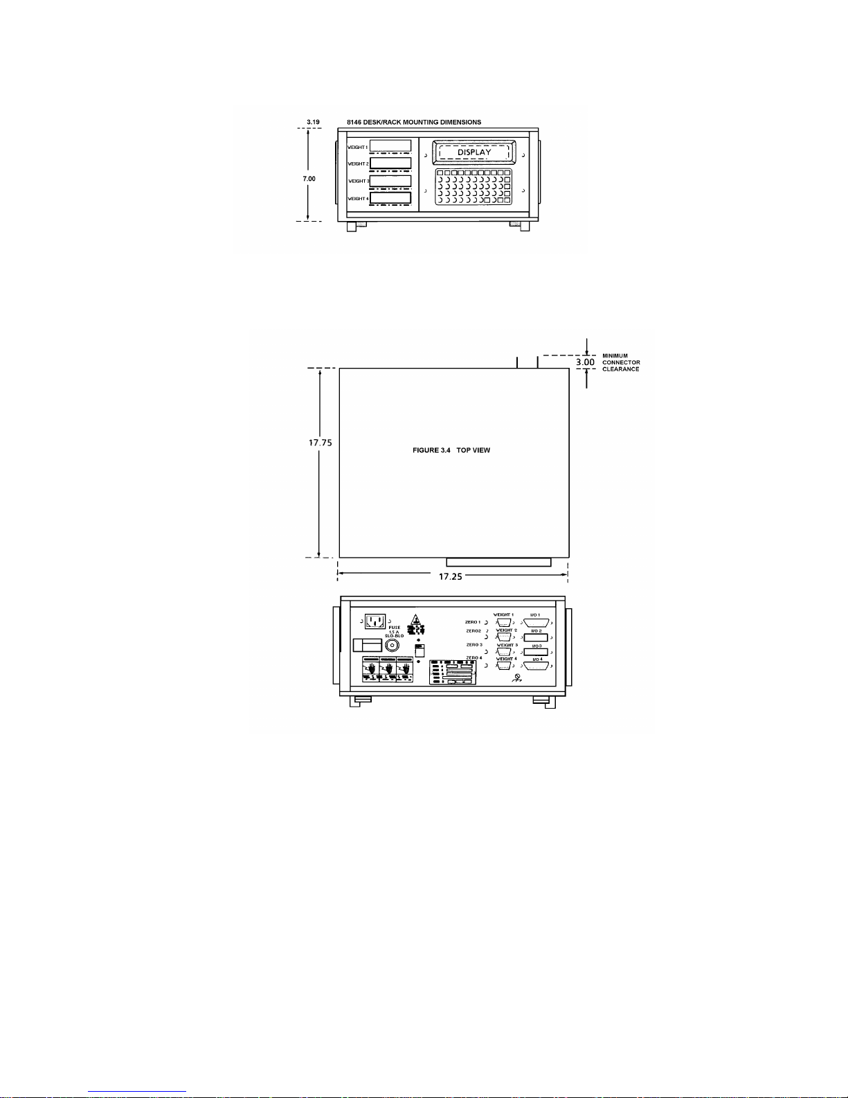
Desk Mount - This unit is charcoal black in color with a blue-green display and green display lens. The
unit’s metal case is 7” (17.8 cm) tall, [8.8” tall (22.4 cm) with legs extended] X 17.25” (43.8
cm) wide X 17.75” (45.1 cm) deep.
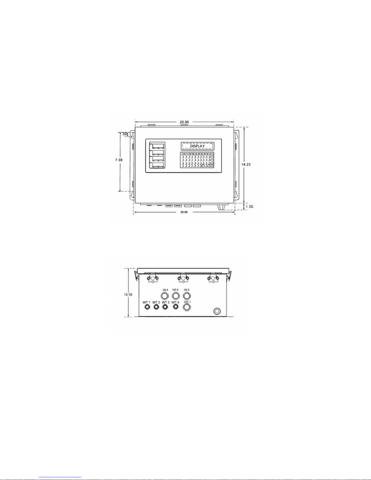
Wall Mount - This unit is a stainless steel NEMA 4X enclosure with a blue-green display and green
display lens. The enclosure is 14.25” (36.2 cm) tall X 20” (50.8 cm) wide X 10.5” (26.7 cm)
deep.
Page 13
7
3.1.7 Hazardous Areas
In locations classified as hazardous by the National Electrical Code (NED) because of combustible or
explosive atmospheres, special modules are required. Toledo Scale Intrinsic Safety Modules are
designed for use in NEC Class I, or Class II, Division I, Groups C, D, E, F, or G. These Intrinsic Safety
Modules may be used ONLY with specific versions of the 8146. DO NOT CONNECT INTRINSIC SAFETY
MODULE TO ANY OTHER VERSION OF THE 8146. Contact Toledo Fast Factory for additional
information.
3.1.8 8146 Wall Mounting Dimensions
Figure 3.1 Front View
Figure 3.2 Bottom View
Page 14
8
3.1.9 8146 Desk/Rack Mounting Dimensions
Figure 3.3 Front View
3.2 INTERNAL FUNCTIONS
The 8146 contains the necessary electronics to calculate and display weight as well as the capability to
transmit data to a remote device.
Figure 3.5 Back View
Page 15
9
3.3 DISPLAY FORMATS
3.3.1 Weight Displays
The weight display is a 7-digit vacuum fluorescent-type, 0.512 inches high with a lighted decimal point.
A lighted comma may be selected to replace the decimal point by inserting a jumper plug across two
pins located on the Weight Display PCB. (See Section 4.4.6.) The display also includes seven vacuum
fluorescent descriptors which are located underneath the digits. These descriptors are ZERO, LB, KG,
GROSS, NET, TARE, and SELECT. Their functions are as follows:
ZERO When illuminated, this indicates that the scale is on gross zero.
LB or KG Indicates the unit is in the pounds or kilogram mode.
GROSS When illuminated, this indicates that the displayed value is the gross weight.
Gross = Tare + Net
TARE When illuminated, this indicates that the displayed value is the tare weight.
Tare = Gross - Net
SELECT When illuminated, this indicates which scale has been selected for further operations.
The 8146 may have two Weight Display PCB’s installed -- with each Weight Display PCB having two 7digit displays. This allows the 8146 to display the weight on each of the four possible scales at the same
time. With only two scales, it is possible to display the Gross or Net and Tare of each scale.
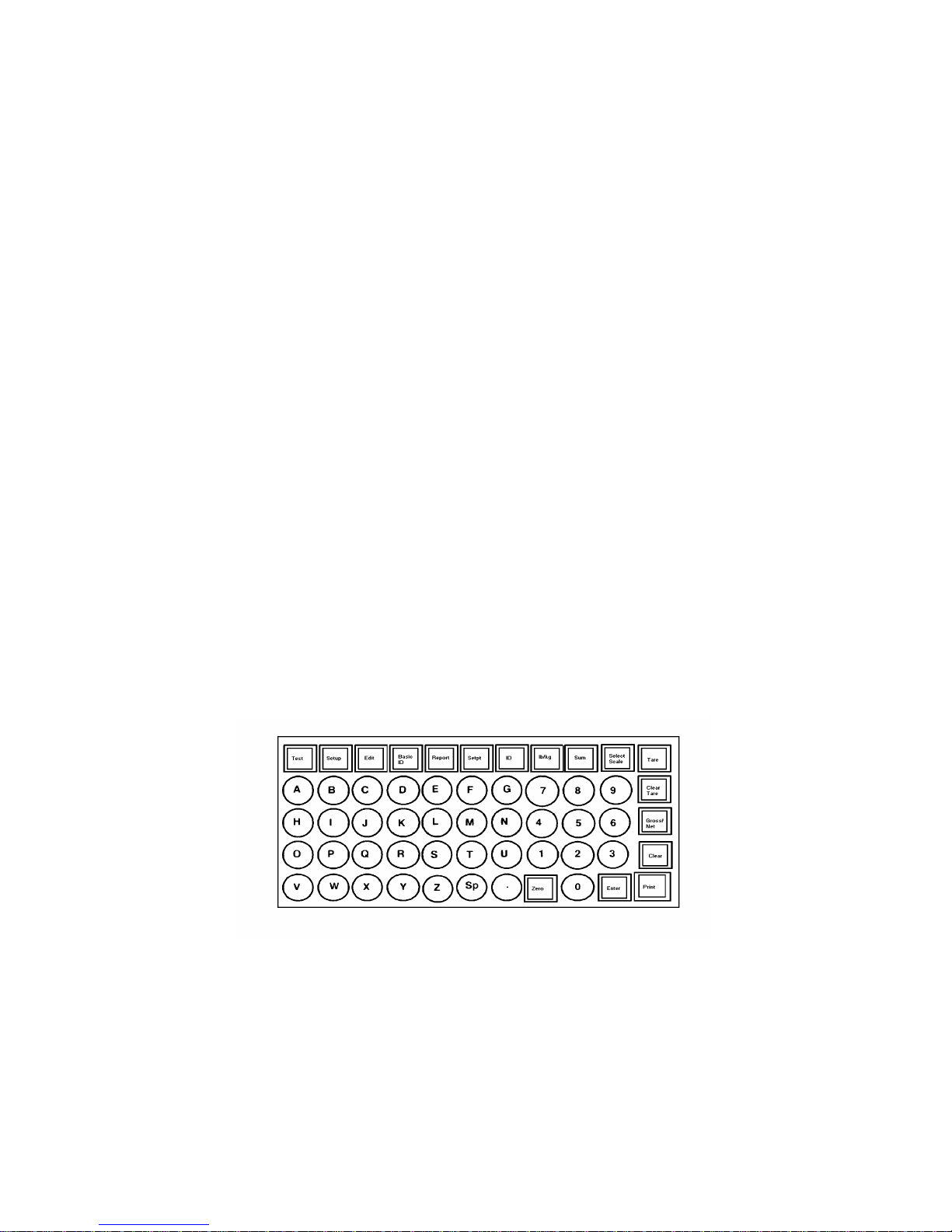
3.3.2 Data Display
The data display is a 16-character alphanumeric, dot matrix type. The characters are 0.44 inches high.
This display is used to prompt the operator throughout the various operating sequences as well as
display the results of the operation.
Figure 3.6 Keyboard Layout
Page 16

10
3.4 KEYBOARD SPECIFICATIONS
The keyboard is a 55-position, tactile feedback keyboard with the edge of each key raised. The keys are
arranged as follows:
A-Z Used to enter the appropriate character when prompted for an alphanumeric input.
0-9 Used to enter the appropriate digit when prompted for a numeric value.
Test Initiates the internal self-diagnostics. This routine will continue until the second
depression of the test key
Setup Used to enter setup mode in conjunction with setup lockout switch(es).
Edit This key is used to view or change the contents of the ID, CN, Time, Date, Stored Tare,
Subtotals and Totals data.
Basic ID Used to enter a 16-character identification.
Report Used to initiate report printing sequence
Setpt Used to view or change the value of any of the twelve setpoints.
ID Used to access the tare recall function, for stored weight operation.
lb/kg Used to alternate between the lb and kg display mode. This key may be disabled in the
setup procedure.
Sum Used in conjunction with a numeric key (1-4) to select the scales that are to be summed.
Also used in conjunction with the Select Scale key to select sum display of previously
entered scales.
Select Used in conjunction with a numeric key (1-4) to select a particular scale for subsequent
operations. Also used with the Sum key for recalling the summed weight to the
alphanumeric display.
Tare Used to initiate an autotare.
Clear Clears the tare applied to the selected scale. The operation of this key is dependent upon
the
Tare programming of the tare function.
Gross/Net Alternately selects between the gross and net display modes.
Clear Used to clear any erroneous entry of numeric data.
Print Used to initiate a data transmission through the printer interface.
Enter Used to terminate any entry.
Zero Used to zero the selected scale’s weight display.
3.5 FACTORY NUMBER CONFIGURATION AND OPTIONS
3.5.1 Configuration Chart
Page 17
11
All factory numbers are configured with one Weight Display PCB. Scale interface kits are ordered as
options. (See chart below.)
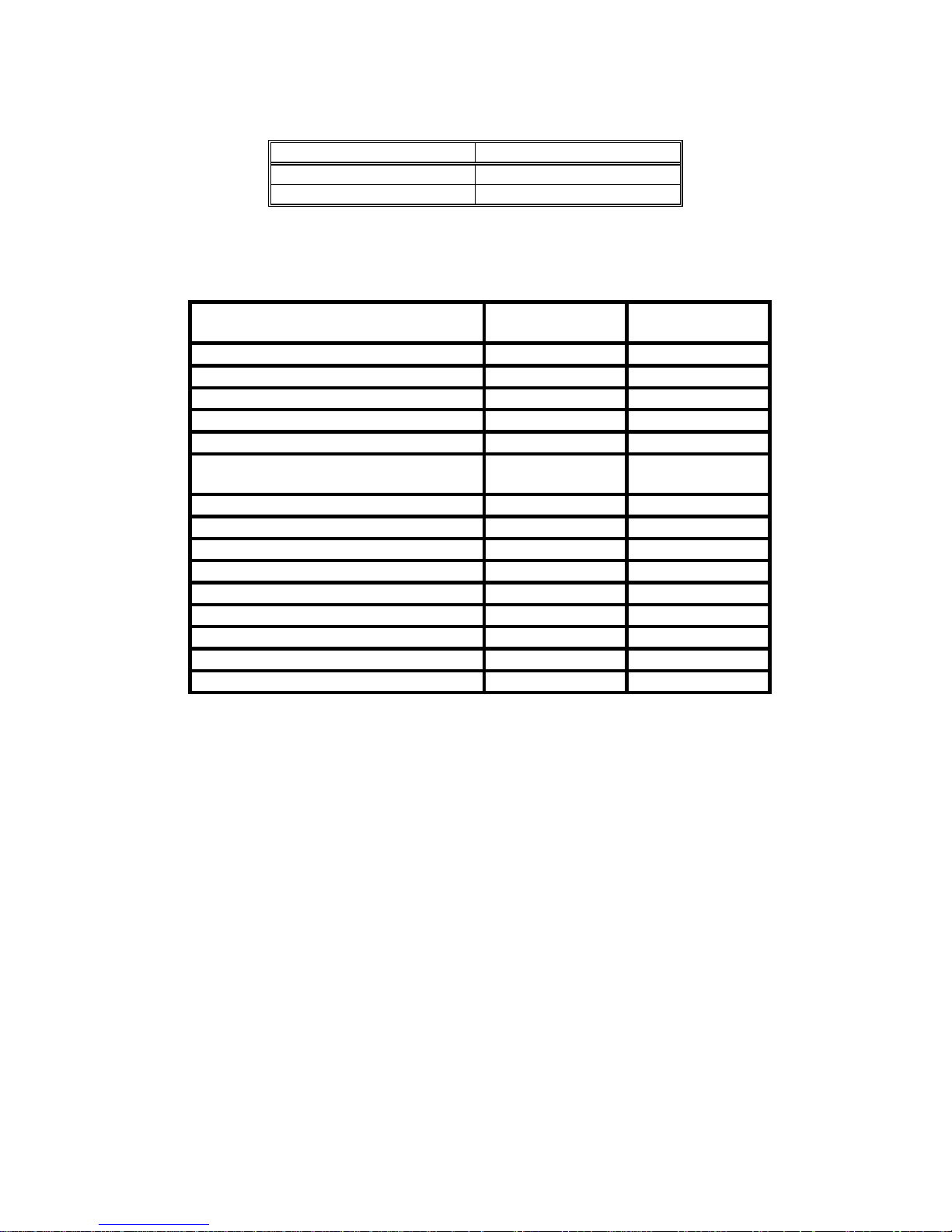
Factory Number Mounting
8146-0022 Desk
8146-0032 Wall
Figure 3.7 Factory Number Configuration Chart
3.5.2 Options
Descriptions
Service
Part Number
Sales
Part Number
Analog Scale KOP, Desk 127480 00A 0917-0126
Analog Scale KOP, Wall 124781 00A 0917-0127
Dual Serial I/O KOP, Desk 127482 00A 0917-0128
Dual Serial I/O KOP, Wall 127483 00A 0917-0129
Rack Mount KOP, Desk *** 127484 00A 0917-0130
Additional Weight Display KOP,
134367 00A 0917-0174
Desk
Additional Weight Display KOP, Wall 134369 00A 0917-0175
Tool-Operated Zero Pushbutton KOP 128235 00A 0917-0137
Scale Channel KOP (Analog KOP) 134365 00A 0917-0173
Weight Display Lens KOP, Desk* 134373 00A 0917-0176
Weight Display Lens KOP, Wall * 134374 00A 0917-0177
DigiTOL ® Scale KOP, Desk ** 134361 00A 0917-0171
DigiTOL ® Scale KOP, Wall** 134363 00A 0917-0172
DigiTOL ® Scale KOP, Desk ** 0917-0179
DigiTOL ® Scale KOP, Wall ** 0917-0180
Figure 3.8 Factory Options Chart
NOTE(S):
* Weight 1, Tare 1, Weight 2, Tare 2
** DigiTOL ® Power Cells
*** DigiTOL ® Bench Portable and DigiTOL ® J-Box
**** Factory Installed Option - Not Available as Field Installed KOP.
Page 18

12
3.6 DATA INTERFACE
3.6.1 Printer Output
The 8146 is capable of transmitting bit serial, ASCII coded, data stream at 300 to 9600 baud. 20mA
current loop, EIA RS232-C and EIA RS422 are all available as standard circuit types.
3.6.1.1 Demand Operation - 300 to 9600 baud
When a print command is received, either from the print key or an external “Print Demand” signal via the
host port, the 8146 will transmit a message which was formatted during the printer output setup
procedure. Transmission of a checksum character, as well as expanded print, is selectable in the same
setup procedure.
3.6.1.2 Continuous Operation - 300 to 9600 baud
Setpoint status is transmitted via serial port in an ASCII coded format. This format is compatible with a
Reliance Electric AUTOMATE 15 TM programmable controller. This allows a standard AUTOMATE 15 to
be used as a setpoint output controller. Communications are via a standard ASCII RS232 serial link, at
9600 baud, 8 data bits, 1 stop, no parity into the programming port on the AUTOMATE 15. The first 12
bits in the first I/O rail [0.00 through 0.13 (octal)] are assigned to setpoint outputs 1-12. The last output
rail (0.17) is assigned as a toggling watchdog bit, with state complimenting at each I/O update. The
other bits in the rail (0.14, 0.15, and 0.16) are allocated, but of indeterminate state. The AUTOMATE 15
may be programmed to use the setpoint bits as internal points, but MUST NOT ALTER THE OUTPUT
STATES. All other available I/O points (1.00 through 3.17) are usable to the AUTOMATE 15. Any digital
output module usable with the standard AUTOMATE 15 head may be used for setpoint control.
Automate head must have an address of 01, i.e., PCID = 1. Refer to Section 6.9 for a detailed description
of this output.
3.6.3 Bar Code I/O - Optional
This port provides a bi-directional, bar code interface. 20ma current loop and EIA RS232-C circuit types
are supported. Baud rates are selectable from 300 to 9600 baud. Refer to Section 6.8 for a more detailed
description. Bar Code output is available for use with the 8860 Thermal Label Printer.
3.6.4 Computer I/O - Optional
This port provides a bi-directional interactive computer interface. EIA RS232-C and 20 mA Current Loop
are available at 300 to 9600 baud. Refer to Section 6.7 for message format, content and protocol.
Page 19

13
4.0 INSTALLATION INSTRUCTIONS
4.1 PRELIMINARY INSPECTION
4.1.1 Inspection of Outer Case
Inspect the outer case for loose or damaged parts. If any damage is found, immediately notify the
freight carrier.
4.1.2 Inspection of Instrument
Open the instrument and continue the inspection noting that all interconnecting harnesses are securely
fastened.
4.1.2.1 The desk unit is opened by removing the four screws (two on the top cover plate and two on
the rear panel) and slide the top cover plate towards the rear of the unit.
4.1.2.2 The wall mount is opened by flipping the wing-type handle of each fastener up and turning
them 180 degrees counter-clockwise. Loosen the hinge fasteners of the bottom of the unit last.
4.2 OPERATING VOLTAGE SELECTOR
The operating voltage selector is located on the rear panel for the desk mount and inside the enclosure
on the wall mount. Locate this selection switch and verify that the correct operating voltage is selected
for installation.
! CAUTION
DO NOT APPLY POWER TO UNIT UNTIL VOLTAGE
HAS BEEN VERIFIED AND POWER SELECTION HAS
BEEN MADE.
! CAUTION
BE CERTAIN POWER IS DISCONNECTED BEFORE
MAKING ANY ADJUSTMENT TO THE
TRANSFORMER FOR VOLTAGE CHANGES.
Page 20

14
4.2.1 To adjust the voltage selection switch, loosen the two screws and slide the locking plate until the
correct voltage level is showing. Possible selections are: 120, 220, and 240 volts AC.
! CAUTION
IF THE OPERATING VOLTAGE IS CHANGED, BE
SURE THE FUSE IS REPLACED WITH A FUSE OF
THE CORRECT RATING.
120 VAC operation requires a 1.5 amp Slo-Blo Fuse
220 VAC operation requires a .75 amp Slo-Blo Fuse
240 VAC operation requires a .75 amp Slo-Blo Fuse
4.3 PRELIMINARY CALCULATIONS (APPLICABLE WITH ANALOG PCB ONLY)
Before connecting the 8146 to an understructure, it should be determined if the load cell(s) are of a size
that will work correctly with the instrument and platform. If it is a standard build, proceed with
installation of the scale. However, if it is a special build or a conversion of an existing mechanical scale,
the microvolt per increment should be calculated. After calculating the microvolt per increment build,
refer to the build charts to verify that the 8146 will operate correctly with this build.
4.3.1 To find the microvolt per increment build, you must first find the following items:
a) Scale capacity*
b) Increment size *
c) Number of load cells or total lever ratio
d) Load cell capacity
e) Load cell output rating in mV/V (millivolts per volt of excitation)
* in lb or kg depending on how the scale is to be calibrated and used.
4.3.2 Find the total load cell output in millivolts by multiplying the cell output rating* by the 8146
excitation voltage, 6 or 15 volts.*
NOTE: Toledo Scale load cells are 2mV/V. Other manufacturers’ load cells may be 1, 1.75, or
3mV/V. Standard excitation is 15 VDC, reduced excitation is 6 VDC.
4.3.3 Use the formula shown to calculate the microvolt per increment ratio.
IncrementSize TotalLoadCellOutput mV x
LoadCellCapacityxNumberofCells orLeverRate
4.3.4 Divide scale capacity by the increment size to determine the number of increments which will be
used.
4.3.5 The following microvolt chart shows the limits, in microvolts, for the number of increments used.
& ( )
( )
1000
The 8146 Analog PCB’s are designed to operate with a maximum microvolt input of either 30 or
45uV*. This selection is determined by the position of the W3 jumper located on the Analog PCB.
Verify the position of this jumper on all Analog PCB’s installed in your unit. It may be necessary
to change this jumper position to reach an acceptable microvolt per increment build on your
unit.
* The maximum microvolt input is found by multiplying the excitation times the millivolt
output rating of the load cell.
Page 21

15
Number of Increments*** Minimum µV/INC** Maximum µ/V/INC*
1,000
1,200
1,500
2,000
2,500
3,000
4,000
5,000
6,000
8,000
10,000
12,000
15,000
16,000
20,000
25,000
30,000
32,000
35,000
40,000
45,000
48,000
50,000
3.0
2.5
2.0
1.5
1.2
1.0
0.75
0.6
0.5
0.375
0.3
0.3
0.3
0.3
0.3
0.3
0.3
0.3
0.3
0.3
0.3
0.3
0.3
38.0
31.7
25.3
19.0
15.2
12.7
9.5
7.6
6.4
4.8
3.8
3.2
2.5
2.4
1.9
1.5
1.3
1.2
1.1
0.95
0.84
0.80
0.76
* The 8146 cannot be calibrated on builds that are greater than shown for the maximum
µV/Increment.
** The 8146 should never be programmed to less than .3uV/Increment for multiple cell scales
(4 or more) and no less than 1.0uV/Increment for single cell scales.
*** The number of increments shown are the only selections which should be made. If these
limits are exceeded, the scale may not be stable.
Page 22

16
Number of Increments*** Minimum µV/INC** Maximum µ/V/INC*
1,000
1,200
1,500
2,000
2,500
3,000
4,000
5,000
6,000
8,000
10,000
12,000
15,000
16,000
20,000
25,000
30,000
32,000
35,000
40,000
45,000
48,000
50,000
3.0
2.5
2.0
1.5
1.2
1.0
0.75
0.6
0.5
0.375
0.3
0.3
0.3
0.3
0.3
0.3
0.3
0.3
0.3
0.3
0.3
0.3
0.3
Figure 4.2 Microvolt Chart for Analog PCB With
Jumper W3 Set Between Pins 2 and 3 (30mV)
26.0
21.7
17.3
13.0
10.4
8.7
6.5
5.2
4.4
3.3
2.6
2.2
1.7
1.6
1,3
1.0
0.87
0.81
0.74
0.65
0.58
0.54
0.52
* The 8146 cannot be calibrated on builds that are greater than shown for the maximum
µV/Increment.
** The 8146 should never be programmed to less than .3 µV/Increment for multiple cell scales (4
or more) and not less than 1.0 µV/Increment for single cell scales.
*** The number of increments shown are the only selections which should be made. If these limits
are exceeded, the scale may not be stable.
Page 23

17
4.3.6 Example of finding the µV/Increment build
Scale Capacity 5000 lb
Increment Size 1 lb
Number of Cells 4
Size of Cells 2000 lb
Cell Output Rating 2 µV/V
8146 Excitation 15 V
MODEL 2155
Step 1 Find the total load cell output in millivolts (mV).
2mV/V x 15V = 30mV
Step 2. Use the formula to find µV/Increment
1 lb x 30mV x 1000
2000 lb x 4
Step 3 Divide scale capacity by increment size to determine number of increments to be
programmed.*
= 3.75 µV/Inc.
50001lb
lb
Step 4 Check the Microvolt per Increment Chart to see if this build fits into the 5000 increment range.
If it does, this will be a satisfactory build and you can continue with the installation.
If it does not, do not continue with this installation until the problem is corrected.
= 5000 Increments
*
select the closest range from the chart, as only the values in the chart are legitimate builds.
Page 24
18
4.4 JUMPER DESCRIPTION AND RECOMMENDED SETTINGS
This section of the manual describes the function of the onboard jumpers and program switches as well
as their recommended settings for use in the Model 8146. Refer to the following paragraphs by
individual PCB to determine how the jumpers or switches are to be positioned. Selections shown are
the required settings for correct operation of the 8146 indicator.
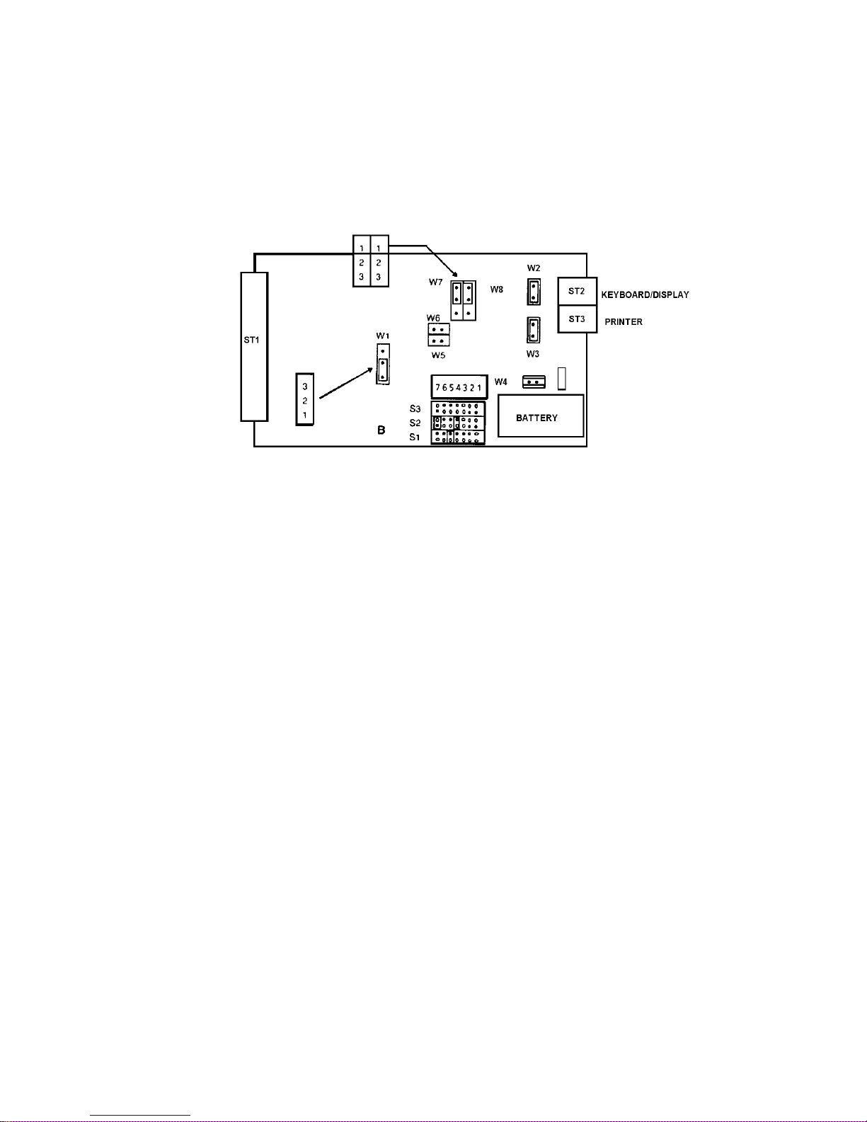
4.4.1 CPU PCB
W1 - RAM Size
Pins 1 to 2 = 8K RAM
W2 - CTS Level for Connector ST2
Pins Connected = Inactive CTS
W3 - CTS Level for Connector ST3
Pins Not Connected = Active CTS
*Pins Connected = Inactive CTS
W4 - Battery Backup
Pins Connected = Battery Active
W5 and W6 - On-board Address Selection
Both of these jumpers must be set so that the pins are not connected.
W7 and W8 - Off-board Address Selection
Both of these jumpers should be installed between Pins 1 and 2.
S1-5
Pins connected = Clock Interrupt
S2-4
Pins Connected = Host/Bar Code Serial Receive Interrupt
S2-7
Pins Connected = Printer Serial Receive Interrupt
*Factory Setting
Page 25
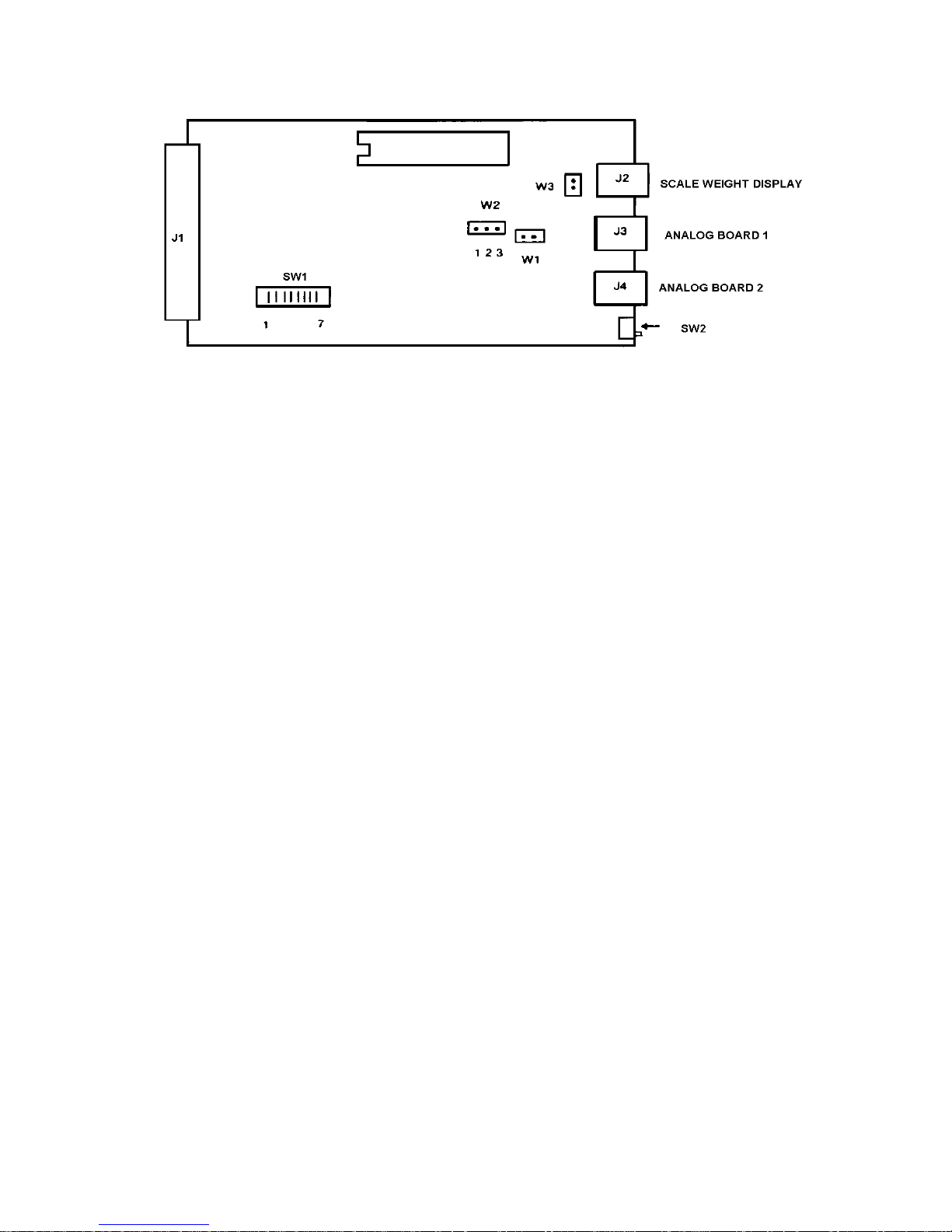
19
SWITCH 1-1 ON - For the first Scale Channel PCB in the unit
OFF - For the second Scale Channel PCB in the unit
1-2 MUST BE ON
1-3 MUST BE ON
1-4 MUST BE ON
1-5 MUST BE OFF
1-6 MUST BE ON
1-7 MUST BE OFF
SWITCH 2 ON (towards J4)
This switch on the first Scale Channel PCB will allow the setup
procedure to be accessed and calibration of the scales connected to
this PCB. This switch on the second Scale Channel PCB must be
turned ON to access the calibration procedure of any scales connected
to it.
OFF (away from J4)
W1 - PSEN
This jumper must be set so that the pins are connected.
W2 - EPROM Select
Pins 2 to 3 = High Memory Size
W# - CTS Enable
Pins are not connected = CTS Inactive
Prevents access to the setup and calibration procedures.
Page 26
20
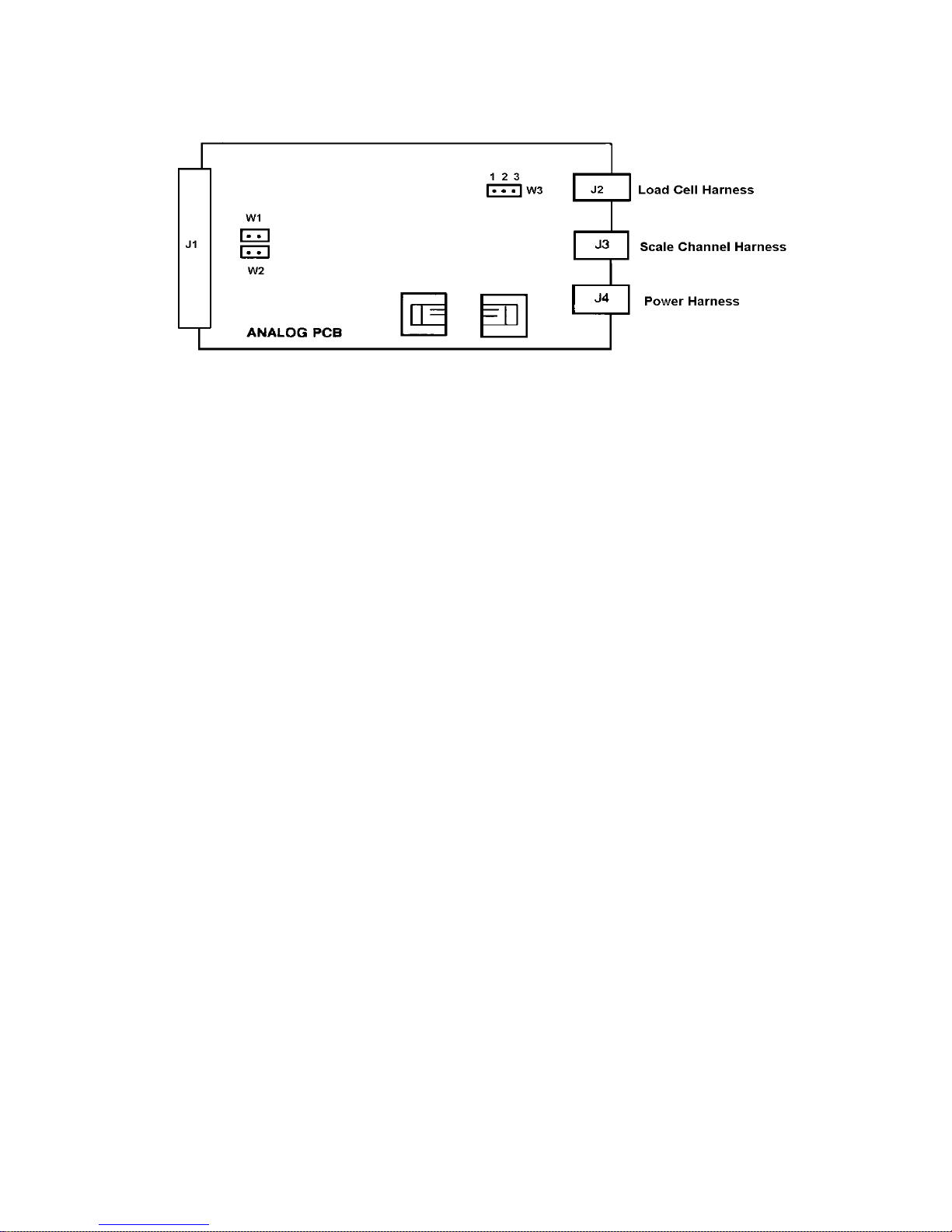
4.4.3 Analog PCB
W1 and W2 - Line Sync
* Pins Connected = AC Line Sync
NOTE: These jumpers must be positioned the same as Jumper W1
Pins not connected = Internal Sync
located on the Power Supply PCB.
W3 - Load Cell Output Selection
3mV/V - For use with 3mV/V load cell(s). This jumper must connect Pins 1 and 2.
2mV/V - For use with 2mV/V load cell(s). This jumper must connect Pins 2 and 3.
* Factory Setting
Page 27
21
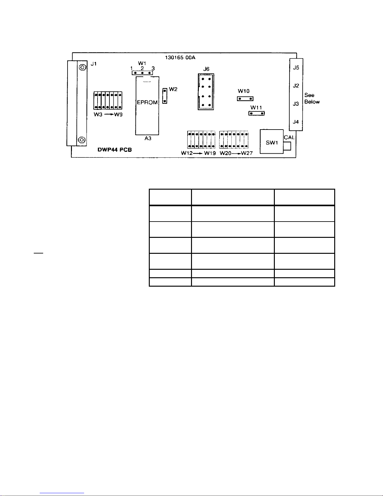
4.4.4 DWP44 PCB
Jumpers installed as follows:
W1 = OVER Pins 2 & 3
W2 = IN (shorting pins together)
W3 = IN for DWP44 #1
W3 = OUT for DWP44 #2
W4, W5, W6 & W8 = IN
NO Jumpers installed
W7, W9 thru W17 = OUT
W19 thru W27 = OU
Connector Usage Internal Harness
Part Numbers
J1 32 Pin TSM Bus Interface
TSM Back Plane
J2 T-LAN & High Speed
Multidrop DLC
J3 Single DLC or DigiTOL ®
J-Box
J4 Single DLC or DigiTOL ®
J-Box
134360 00A Desk
134375 00A Wall
134383 00A Desk
134384 00A Wall
134383 00A Desk
134384 00A Wall
J5 Dual Weight Display 128236 00A
J6 Auxiliary Power Input 118521 00A
Page 28
22
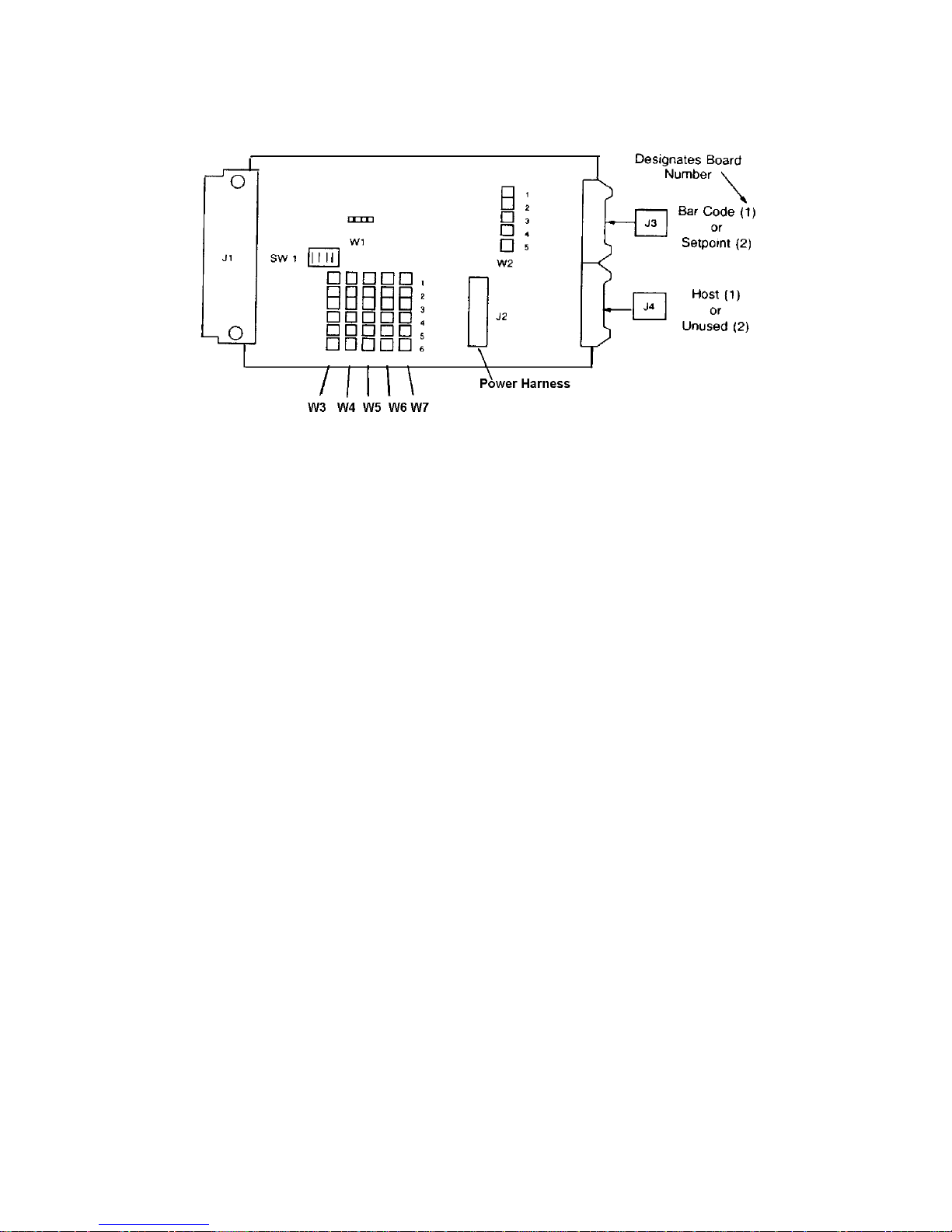
4.4.5 Serial I/O PCB
W3 = Not Used
W4 = 1-2 All Options
W5 = 1-2 Host/Bar Code Only
W6 = Not Used
W7 = Not Used
Switch 1 for the Host and Bar Code Option (1), set switches as follows:
SW1- 1 OFF
SW1- 2 ON
SW1- 3 OFF
SW1-4ON
For the Setpoint Option (2), set switches as follows:
SW1- 1 ON
SW1- 2 OFF
SW1- 3 OFF
SW1-4ON
W1 - Timing Clock
This jumper should be installed between Pins 2 and 3.
W2 - External Device Interfacing (CTS and DSR)
For normal operation this should have two jumpers installed. These jumpers
should be installed across pins 1 and 2, and pins 4 and 5. Pin number 3 should
not be connected.
NOTE: 8146’s may contain 0, 1, or 2 Serial I/O PCB’s. Board (1) is used for the Host and
Bar Code options. Board (2) is used for the Setpoint option. Both are ordered as 917-0128 KOP, for desk units, or 0917-0129, for wall units, then configured using
SW1 as shown.
Page 29
23
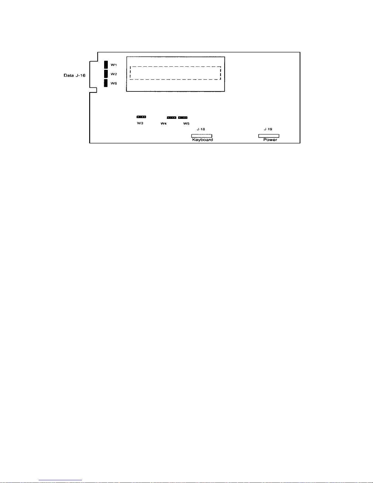
4.4.6 Dot Matrix Display PCB
W1 - Data Output Circuit Type
W2 - CTS Circuit Type
W3 - Test
Pins 2 to 3 = RS232-C Output
Pins 2 to 3 = RS232-C Output
Used to start the self test of the Display PCB. During this test any key
pressed will advance across the display. The pins should not be
connected for normal operation.
W4 - On-board ROM Enable
Pins Not Connected = On-board ROM
W5 - Chip Select
These pins must be connected
W6 - DSR Circuit Type
Pins 2 to 3 = RS232-C Input
Page 30
24
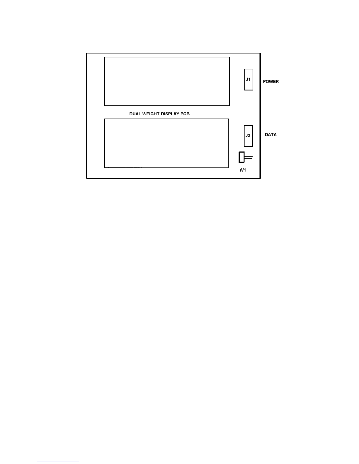
4.4.7 Dual Weight Display PCB
W1 - Comma
Pins not connected = Decimal point on the display
Pins connected = Comma on the display
(Later versions have solder pads only).
Page 31

25
4.4.8 Dual Serial Converter PCB
W1 - Data Input Circuit Type (Keyboard/Display)
W2 and W3 - Data Handling Selection
Pins 2 to 3 = RS232-C Input
Both of these jumpers must have the pins not connected.
W4 - Data Input Circuit Type (Printer)
* Pins 2 to 3 = RS232C Input
W5 Through W8 - Data Handling Selection
All of these jumpers must not have the pins connected.
* Factory Setting
Pins 1 to 2 = RS422 Input
Page 32

26
4.4.9 Power Supply PCB
W1 - Line Sync
Pins not connected = Internal Sync
Pins Connected = AC Line Sync
NOTE: This jumper must be positioned the same as Jumpers W1 and W2 located on the Analog PCB’s.
POWER SUPPLY PCB
!WARNING
THE POWER SUPPLY PCB CONTAINS VOLTAGES IN EXCESS
OF 400 VOLTS. USE CARE WHEN TESTING VOLTAGES.
Page 33

27
5.0 PROGRAMMING PROCEDURE
This section of the manual describes the programming of the indicators’ operating modes and features
as well as the self-calibrating procedure.
The procedure consists of two major groups which deal with the overall setup and calibration of the
indicator. Each major group contains a description of the setup and calibration procedure. Section 5.1
details the procedure for the analog type units and Sections 5.2 thru 5.6 detail the procedure for the
DigiTOL ® type units.
All question prompts and their current status, which affect the overall operation of the indicator, are
displayed on the 16-character alphanumeric display. Questions which deal with the operation of a
specific scale will be displayed on the associated scale’s weight display.
Five front panel keys are used throughout this procedure. The keys’ names and their functions are as
follows:
KEY NAME DESCRIPTION
SETUP This key is used to enter into the setup procedure. It is also used to exit this procedure at
any point in the procedure except during calibration.
ZERO This key is used to back up to the previous question.
ENTER This is used to accept the currently displayed answer to the question prompt.
1 This key is used as a “YES” response to the question prompt and will enable the displayed
function.
0 This key is used as a “NO” response to the question prompt and will disable the displayed
function. It is also used to increment to the next possible selection if the question consists
of several possible choices.
TO ENTER INTO THE SETUP PROCEDURE YOU MUST FIRST TURN “ON” THE SETUP LOCKOUT
SWITCH(ES) -- (SWITCH “2” ON THE ADP-51, SWITCH “1” ON THE DWP-44) LOCATED ON THE SCALE
CHANNEL PCB(S) OR THE DWP44 PCB(S). If there are two PCB’s installed in your unit, both switches
must be turned “ON” to access the setup prompts. The ON position is when the switch handle is toward
the J4 connector. (Switch “2” on the ADP-51, Switch “1” on the DWP-44).
The following chart can be used as a quick reference for programming descriptions. Also listed is the
recommended selection for each step as a beginning point of initial setup. Verify each selection to be
certain that it is correct for actual usage.
Page 34

28
5.1 ANALOG SETUP AND CALIBRATION PROCEDURE
(for use with Analog type load cells)
8146 PROGRAM FUNCTIONS
STEP DESCRIPTION INITIAL
SETUP/CALIBRATE SCALES
F2.0 TARE FUNCTIONS
F2.1 TARE ACTIVE 1
F2.2 TARE INTERLOCK 0
F2.3 AUTO CLEAR TARE 0
F2.4 TARE DISPLAY ACTIVE 1
F3.0 POWER-UP FUNCTIONS
F3.1 POWER-UP TIME 0
F3.2 POWER-UP POUNDS 1
F3.3 LB/KG SWITCHING 1
F3.4 EXPAND MODE 0
F3.5 SPAN ADJUST 0
F4.0 AVERAGING, ZERO, AND AZM FUNCTIONS
F4.1 AUTO ZERO MAINTENANCE 3
F4.2 EXPANDED ZERO CAPTURE 0
F4.3 PUSHBUTTON ZERO 1
F4.4 ZERO CAPTURE RANGE 2
F4.5 MOTION SENSITIVITY 07
F4.6 MOTION DETECTION 03
F4.7 DIGITAL FILTERING 1
F4.8 ANALOG VERIFICATION 0
SETUP
CAL ACCESS CALIBRATION
5.1 ANALOG SETUP AND CALIBRATION PROCEDURE
(FOR USE WITH ANALOG TYPE LOAD CELLS)(CONTINUED)
Displayed Prompts Descriptions
[Setup Scale X] SETUP/CALIBRATE SCALES?
This is the first prompt after entering the setup procedure and is displayed on the alphanumeric display.
If you want to setup, calibrate or make any changes which deal with any one of the four possible scales
connected, simply enter that scale’s number (1-4) and the routine will advance to F2.0. All prompts
which deal with the selected scale will be displayed on that scale’s weight display. If you do not want to
enter into this routine, enter a 0 and the procedure will skip to F5.0.
NOTE: This prompt will remain on the display throughout this routine. At the end of each scale’s
setup, the weight display will return to normal. At this time, the unit is asking for the next
scale number or a 0 to continue. The routines that deal with each scale are: F2.0, F3.0, F4.0,
and CAL.
[F2.0 ] ACCESS TARE FUNCTIONS? Press:
1 To enter into the setup of all tare functions.
0 To skip the tare setup. The procedure will advance to step F3.0.
[F2.1 ?] TARE ACTIVE. Press:
1 To enable both the hand entered and auto tare function.
Page 35

29
0 To disable the tare function.
[F2.2 ?] TARE INTERLOCK. Press:
1 The indication must be at true zero before tare can be removed. (True Zero is actually zero
minus the tare value). Previous tare must be cleared before a second tare may be entered.
This also disables a weight display on power up. The display will flash EEE until zero is
captured.
0 The tare value may be cleared or changed at any weight indication. Multiple tare will be
accepted. The indication will power up with a non-flashing weight display.
[F2.3 ?] AUTO CLEAR TARE. Press:
1 The tare value will automatically clear when the indication returns to zero after settling to a
no-motion condition at a weight greater than 10 minor increments.
0 Tare must be cleared manually by using the Clear key.
[F2.4 ?] TARE DISPLAY ACTIVE. Press:
1 The tare value will be displayed on the lower weight display. This is only usable when the
8146 is configured as a dual display unit.
0 The tare value will not be displayed.
[F3.0 ] ACCESS POWER UP AND lb/kg SELECTION? Press
1 To enter into the setup of the power up and lb/kg selections
0 To skip these setup selections. The procedure will advance to step F4.0.
[F3.1 ?] POWER UP TIMER (Approx. 30 seconds). Press:
1 The weight display(s) will remain blank and the legend indicators will blink until the time-
out period has elapsed.
0 The weight display(s) will illuminate as soon as power is applied.
[F3.2 ?] POWER UP POUNDS. Press:
1 The 8146 will power up in the lb mode.
0 The 8146 will power up in the kg mode.
[F3.3 ?] lb/kg SWITCHING. Press:
1 To enable the switching between the lb and kg modes via the keyboard.
0 To disable lb/kg switching. The unit will operate in the selected power up mode.
Page 36

30
[F3.4 ?] EXPAND MODE. Press:
1 The weight display will be expanded (showing minor increments).
0 The weight display will not be expanded (showing major increments).
NOTE: The 8146 should not be left in the expand mode for weighing. This mode is for
installation evaluation and troubleshooting only. The Print, AZM, and Zero keys are
disabled in this mode.
[F3.5 ] SPAN ADJUST. Press:
1 To enter into the span adjust. The standard calibration must be completed to provide a
reference point before attempting to use this step. Refer to section 5.1.1 for a detailed
description of the span adjustment feature.
0 A “0” will be displayed on the right of the display and the span adjust mode will not be
accessed.
[F4.0 ] ACCESS SCALE PARAMETER SELECTIONS: Press:
1 To enter into the setup of the scale parameter selections.
0 To skip the scale parameter selections. The procedure will advance to step CAL.
[F4.1 ?] AUTO ZERO MAINTENANCE
This selection allows for different AZM band and rate selections. The band size is the
maximum amount of increments which can be adjusted for, and the rate is the amount of
adjustment per cycle. Key in the appropriate selection from the chart below and then press
“ENTER”.
AZM Selection AZM Range
0 AZM Disabled
1 ± 0.5 increment with 0.1 rate
2 ± 1.0 increment with a 0.2 rate
3 ± 3.0 increments with a 0.4 rate
[F4.2 ?] EXPANDED AZM CAPTURE RANGE. Press:
1 To increase the AZM range from ± 2% up to ± 10% of the scale capacity.
0 The AZM range will not be increased.
[F4.3 ?] PUSHBUTTON ZERO. Press:
1 To enable the front panel Zero pushbutton.
0 To disable the front panel Zero pushbutton.
Page 37

31
[F4.4 ?} PUSHBUTTON ZERO CAPTURE RANGE
This prompt is requesting the percent of the scale capacity that can be captured by using the
Zero pushbutton. This entry is selectable from 2 to 20% of scale capacity.
[F4.5 07] MOTION SENSITIVITY SELECTION
The detection of motion disables printing, tare, and pushbutton zeroing. Steps F4.5 and F4.6
program the sensitivity of motion detection. Changes in weight greater than F4.5 (minor
increments) over the time required to perform F4.6 (A/D cycles) are detected as motion. The
“in motion” signal is provided as a status bit in the output data when the continuous output
mode is selected.
Sensitivity of motion is the amount of change in weight allowed before motion is detected.
The sensitivity can be programmed in a range from 0.1 to 3 major increments in steps 0.1
increment.
To determine what number to enter in this step, use the following procedure. Valid
selections are 0* through 30 with 07 recommended as a beginning value.
* Determine the number of increments (or part of an increment) that the sensitivity should be.
For example, 0.5, 1 or 0.7 increment. Multiply this number by 10. Example: If the number
selected is 0.7, multiply this by 10 to get 7. This result (7) is the number to be entered for
step F4.5.
NOTE: If a value of “0” is entered there will be no motion detection and prompt F4.6 will be
skipped.
[F4.6 03] MOTION DETECTION RANGE
This step programs the number of A/.D cycles over which the 8146 will monitor weight
changes. The changes in weight must be less than the value programmed in step F4.5 to
obtain a “no motion” signal. Numeric values between 1 and 20 A/D cycles are selectable with
a beginning value of 3 recommended. The “ENTER” key must be pressed to proceed to step
F4.7.
NOTE(S):
1 The update rate of the 8146 (A/D cycles per second) is dependent upon the number of
full scale increments and the amount of initial weight. It varies from approximately 11 (at
1,000 total increments) to 4 (at 50,000 total increments).
2 The smaller this number is, the greater the probability will be for detecting “no motion”
since it checks for motion over a shorter length of time.
Page 38

32
[F4.7 1] DIGITAL FILTERING SELECTION
This allows selection of different quantities of A/D cycles to be filtered before a display
update. The higher the number, the slower the update. Key in the appropriate selection from
the chart below and then press “ENTER”.
FILTERING SELECTION FILTERING RATE
0 NONE
1 LIGHT
2 MEDIUM
3 HEAVY
4 VERY HEAVY
[f4.8 ?] ANALOG VERIFICATION. Press:
1 To enable analog verification.
0 To disable analog verification.
[CAL] ACCESS CALIBRATION MODE? Press:
1 To enter the calibration mode.
0 To skip the calibration mode. (The procedure will return to the Setup Scale prompt.)
NOTE: Error codes that may be displayed during calibration are described in the
troubleshooting section of this manual.
[C1 ] FULL SCALE CAPACITY
[XXXXXX]
This display is showing yhou the programmed scale capacity. If this capacity is correct, press
the “ENTER” Key.
If the displayed capacity is not correct for your scale, enter the desired scale capacity and
press the “ENTER” Key.
[C2 ] INCREMENT SIZE
[XXXXXX]
At this time the unit is asking you to enter the displayed increment size.
If the displayed increment size is not correct for your scale, enter the desired size and press
the “ENTER” key. This entry must include the decimal point or trailing zero if required.
Maximum increment size is 500.
Page 39

33
[C3 X] LINEARITY CORRECTION. Press:
1 To select the two-stage linearity correction
0 To disable the two-stage linearity correction.
NOTE: This step will normally not be required. If after calibration, the indication appears to
be nonlinear, this step may be used to correct this. The use of this step requires that
test weights of 60% of the scale’s capacity be available for calibration.
[SC ] CALIBRATION SHORT CUT
This allows bypassing the actual test weight calibration by entering in previously calculated initial
and span values. These values are determined AFTER the actual test weight calibration has been
completed. To obtain these values, answer YES to the PRINT SETUP prompt at the end of the
setup procedure. The initial and span values needed will be included in the printout of the setup
parameters. Press:
1 If the short cut initial and span values are to be used for calibration, the standard test weight
calibration will be bypassed.
2 If the initial and span values are not to be used, the 8146 will proceed with the standard test
weight calibration procedure.
NOTE: At this time the calibration sequence will follow one of four possible procedures. The
procedure this sequence takes depends on how you answered the “Linearity Correction”
and “Calibration Short Cut” prompts. Use the following chart to determine which
procedure you should follow.
Linearity Correction Calibration Shortcut Follow
NO NO Procedure A
YES NO Procedure B
NO YES Procedure C
YES YES Procedure D
PROCEDURE A: Normal Calibration without linearity correction
[EP SCL] EMPTY SCALE Remove all weight from the scale platform. Press the
“ENTER” key to continue.
[15 CAL] TIME OUT The display will count down from 15 to 0 while initial is
being set.
[Add Ld] ADD LOAD Place the selected test weights on the scale platform. This
should be at least 10% of the scale’s capacity. Press the
“ENTER” key to continue.
[XXXXXX] TEST WEIGHT The value of the test weights used must be entered.
Fractional or decimal values are not acceptable - only whole
numbers. Press the “ENTER” key to continue.
[15 CAL] TIME OUT The display will count down from 15 to 0 while span is being
set.
[EP SCL] EMPTY SCALE Remove all weight from the scale platform. Press the
“ENTER” key to continue.
Page 40

34
[15 CAL] TIME OUT The display will count down from 15 to 0 while initial is
being reset.
[CAL A] CALIBRATION COMPLETE This display will appear after calibration is complete and will
be displayed for approximately three seconds. At the end of
this time the display will show S FILE for approximately two
seconds. The weight display will then return to normal.
PROCEDURE B: Normal Calibration with linearity correction
[EP SCL] EMPTY SCALE Remove all weight from the scale platform. Press the
“ENTER” key to continue.
[15 CAL] TIME OUT The display will count down from 15 to 0 while initial is
being set.
[Add A] ADD HIGH WEIGHT Place the selected test weights on the platform. This MUST
be greater than 60%, but less than 100% of scale capacity.
Press the “ENTER” key to continue.
[XXXXXX] TEST WEIGHT The value of the test weights must be entered. Fractional or
decimal weights are not acceptable - only whole numbers.
Press the “ENTER” key to continue.
[15 CAL] TIME OUT The display will count down from 15 to 0 while high span is
being set.
[Add B] ADD LOW WEIGHT Place the selected test weights on the platform. This MUST
be greater than 30%, but less than 50% of scale capacity.
Press the “ENTER” key to continue.
[XXXXXX] TEST WEIGHT The value of the test weights must be entered. Fractional or
decimal weights are not acceptable - only whole numbers.
Press the “ENTER” key to continue.
[15 CAL] TIME OUT The display will count down from 15 to 0 while low span is
being set.
[EP SCL] EMPTY SCALE Remove all weight from the scale platform. Press the
“ENTER” key to continue.
[15 CAL] TIME OUT The display will count down from 15 to 0 while initial is
being reset.
[CAL A] CALIBRATION COMPLETE This display will appear after calibration is complete and will
be displayed for approximately three seconds. At the end of
this time the display will show S FILE for approximately two
seconds. The weight display will then return to normal.
PROCEDURE C: Shortcut Calibration without linearity correction
[0 ] “TO” ENTRY Enter the time value obtained for “TO”
[1 ] “T1” ENTRY Enter the time value obtained for “T1”
[FS A] FINE SPAN - HIGH Enter the value obtained for the high order of the fine
Page 41

35
span adjustment
[FS b] FINE SPAN - LOW Enter the value obtained for the low order of the fine span
adjustment
[F0 A] FINE ZERO - HIGH Enter the value obtained for the low order of the fine zero
adjustment
[F0 b] FINE ZERO - LOW Enter the value obtained for the low order of the fine zero
adjustment
[CAL A] CALIBRATION COMPLETE This display will appear after calibration is complete and will
be displayed for approximately three seconds. At the end of
this time the display will show S FILE for approximately two
seconds. The weight display will then return to normal.
PROCEDURE D: Shortcut Calibration with linearity correction
[0 ] “TO” ENTRY Enter the time value obtained for “TO”
[1 ] “T1” ENTRY Enter the time value obtained for “T1”
[FS A] FINE SPAN - HIGH Enter the value obtained for the high order of the fine span
adjustment
[FS b] FINE SPAN - LOW Enter the value obtained for the low order of the fine span
adjustment.
[F0 A] FINE ZERO - HIGH Enter the value obtained for the high order of the fine zero
adjustment
[F0 b] FINE ZERO - LOW Enter the value obtained for the low order of the fine zero
adjustment
[LF - ?] LINEARITY This prompt is asking you in which direction the linearity
factor should be. Enter the value obtained from the printout:
1 A negative linearity factor
0 A positive linearity factor
[LF A] LINEARITY FACTOR - HIGH Enter the value obtained for the high order of the linearity
factor
[LF b] LINEARITY FACTOR - LOW Enter the value obtained for the low order of the linearity
factor
[SF A] SPAN FACTOR - HIGH Enter the value obtained for the high order of the span factor
[SF b] SPAN FACTOR - LOW Enter the value obtained for the low order of the span factor
[S FILE] The display will show S FILE for approximately two
5.1.1 Span Adjustment
The span adjust feature of the 8146 is used to make adjustments to the span without repeating the entire
calibration procedure. This is especially useful on large capacity scales, tank scales and hopper scales
seconds. The weight display will then return to normal.
Page 42

36
where a “build-up” procedure is used for calibration. The procedure for using the span adjust feature is
as follows.
5.1.2
Before span adjust can be used, the standard calibration, as specified in the setup section, must be
performed. It is suggested that as much weight as is practical be used for calibration.
5.1.3
Apply known test weights to the scale. If any adjustment is necessary proceed to the next step.
5.1.4
Enter the setup procedure. Select the correct scale and advance to prompt F3.5. Change the setting of
this prompt to a 1 (yes).
5.1.5
Exit the setup procedure.
5.1.6
Enter the setup procedure and select the correct scale. The data display will now show [Cal Adj 000000].
5.1.7
To make a span adjustment, enter the correct test weight value. Enter all digits including those to the
right of the decimal point. (See Note c below.) Press the “ENTER” key and the normal setup procedure
will begin.
5.1.8
Exit the setup procedure. The weight display should now show the correct weight value. This
procedure may be repeated several times during a “build-up” calibration.
5.1.9
After all adjustments are completed. reenter the setup procedure and change prompt F3.5 to a 0 (NO).
Exit the setup procedure. The indicator is now ready for normal operation.
Page 43

37
NOTES OF INTEREST:
a. This procedure will work correctly once when in the net mode. This is useful if a device to hold the
test weights is required. Simply attach the holding device, then press Tare. Add the test weights,
then follow the span adjustment procedure. After one adjustment, tare must be cleared and then
reentered if required again.
b. Weights that are entered in values other than multiples of the increment size will not be accepted. For
example, entering the 103 pounds when the increment size is 2 lbs.
c. The entire weight value must be entered including numbers to the right of the decimal point. This is
different from the standard calibration where only the numbers to the left of the decimal point may be
entered.
5.2 DIGITOL ® SETUP AND CALIBRATION PROCEDURE
(For Use With DigiTOL® J-Boxes)
00 CELL SELECTION
01 Select Cell Type
02 Load Cell Operation (T-LAN Only)
03 Number of Cells (T-LAN/DigiTOL ® J-Box)
04 Load Cell Address (T-LAN Only)
05 Second Scale Select (T-LAN Only)
06 Reset DigiTOL ® J-Box Shift Constants (DigiTOL ® J-Box Only)
10 CALIBRATION SELECT
11 Calibrate in lb/kg
12 Future
13 Future
14 Scale Capacity
15 Increment Size
16 Future
17 Future
18 Shift Compensation (T-LAN/DigiTOL ® J-Box)
19 Zero and Span Calibration
20 FILTERING AND AZM (All DigiTOL ® types)
21 Zero Adjust
22 Span Adjust
23 AZM Range
24 Auto Zero Capture at Power-Up
25 Push Button Zero
26 Motion Detection
27 Filter Selection
28 Overload Blanking
Page 44

38
30 TARE SELECTION (All DigiTOL ® types)
31 Tare Enable
32 Tare Interlock
33 Future
34 Auto Clear Tare
35 Gross/Net Switching
36 Tare Display Active
80 POWER UP AND UNIT SWITCHING (All DigiTOL ® types)
81 Analog Verify
82 lb/kg Switching
83 lb/kg Power Up
90 LOAD CELL REPLACEMENT (T-LAN Only)
91 Re-Addressing A Load Cell
92 Replacing a Load Cell
93 Shift Adjustment
94 Set Shift Constants
95 Expanded Display Mode
96 Manual Shift Adjust
97 Span/Zero Shift Constants
99 Display Load Cell Output
5.3 SETUP AND CALIBRATION PROCEDURE FOR SINGLE CELL DIGITAL LOAD CELL
SYSTEMS
This procedure describes the setup and calibration for digital load cells used in single cell scales. For
setup and calibration for multiple digital load cell systems, proceed to Section 5.4 (Calibration of
multiple digital load cell systems) or Section 5.5 for DigiTOL ® J-Box.
NOTE: To enter the setup mode when the main display is showing [SCL 1 TR 000000] (8146 Standard
Mode) first move SW1 on the DWP44 PCB toward connector J4. If two DWP44 PCB(s) are
installed, both SW1(s) must be moved to gain entry to all setup parameters for all scales being
used. Press the “SETUP” key. The display will now show [SETUP SCALE?] key in the scale
number to be setup (1 thru 4). The weight display for the scale chosen will show [- - ].
Calibration groups for that scale can now be assessed.
5.3.1 Access Load Cell Type Selection Group 00
[00 ]
With the display prompt at [-- ], enter “00” followed by pressing the “ENTER” key to select GROUP 00
setup parameters. The display will increment to parameter 01.
[01 ]
Press “0” to select the Single, High Resolution DLC mode.
NOTE: If this parameter is being changed from 1 to 0, the indicator must be powered down then back up
before continuing with calibration so that the DWP44 card gets initialized properly for the type of
operation selected.
[01 ] DLC TYPE SELECTION
Page 45

39
0 - Single DLC
1 - Power Cells
2 - DigiTOL ® J-Box
The selection entered for scale One will be forced into the scale Two parameters and this step will be
skipped when setting up scale Two.
Press “0” to select the Single DLC configuration.
The display will return to the [-- ], prompt.
5.3.2 Access Calibration Sequence Group 10
[10 ]
With the display prompt at [-- ], enter “10” followed by pressing the “ENTER” key to select GROUP 10
calibration parameters. Parameters 11 - 19 will be prompted in sequence.
[11 ] CALIBRATE IN LB/KG
Enter the units in which the scale is to be calibrated in.
0 - To calibrate in kg.
1 - To calibrate in lb.
[14 ] ENTER FULL SCALE CAPACITY
The display will show the currently entered full scale capacity. If the capacity is correct, press the
“ENTER” key.
If the displayed capacity is not correct for your application, enter the desired full scale capacity followed
by the “ENTER” key.
[15 ] ENTER INCREMENT SIZE
The display will show the currently entered increment size. If the increment size is correct, press the
“ENTER” key.
If the increment size is not correct, press the “0” key. The display will display zeros. Continue pressing
the “0” key until the decimal point is in the correct position or until the correct number of fixed zeros ar
displayed. Now press the “1”, “2” or “5” key to select the proper increment size. This entry will replace
the “-” character on the display.
[19 ] ZERO AND SPAN CALIBRATION
Press “0” to return to [-- ], prompt, or press “1” to proceed.
The display will show [Add Ld ]. Press the “ENTER” key. The display will blank. Place test weight on
the scale and enter this value using the keyboard followed by the “ENTER” key. The display will count
down from
[16 CAL ] to [ 09 CAL ]. A check is now made to see if enough counts are received from the DLC.. If
not, new T0 and T1 values are calculated and sent to the DLC. The display will then continue to count
down to [ 01 CAL].
If new T0 and T1 counts were sent, then the display will show [E SCL ], otherwise it will proceed to
calibration done. Remove the test weight from the scale and press the “ENTER” key. The display will
count down from
Page 46

40
[16 CAL ] to [01 CAL ].
When calibration is completed, the display will show {CAL ] for two seconds indicating the zero and
span calibration has been successfully completed. The display will then return to the [-- ] prompt.
The remainder of the setup parameters may be directly addressed by entering their two digit code.
However, by entering the group number first, the unit will automatically increment through some or all of
the parameters in that group.
5.3.3 Access Load Cell Replacement Group 90
[90 ]
With the display prompt at [-- ], enter the parameter number and press the “ENTER” key to select the
parameter.
[97 ] DISPLAY AND ENTRY OF SPAN AND ZERO CONSTANTS
With the display at [-- ], enter “97” followed by pressing “ENTER” key to select this parameter. This
parameter allows the operator to view or alter the values stored for span and zero.
0 = To return to [-- ] prompt.
1 = To proceed with the display of these values.
A) The display will show [97A ] for a 1/2 second then display the current span value. Press the
“ENTER” key to retain the current value or enter a new value followed by pressing the “ENTER” key.
B) The display will show [97b ] for a 1/2 second then display the current zero value. Press the
“ENTER” key to retain the current value or enter a new value followed by pressing the “ENTER” key.
C) The display will show [SA ] to save the new values permanently. If you want to save the new values
permanently, press the “1” key. The original values will be replaced by the new ones. If you want to
return to the original values, press the “0” key. The display will return to the [-- ] prompt.
Page 47

41
5.4 SETUP AND CALIBRATION PROCEDURE FOR T-LAN MULTIPLE DIGITAL LOAD
CELL SYSTEMS
This procedure describes the setup and calibration for digital load cell(s) which are interfaced to the
8146 via a T-LAN network.
5.4.1 Access Load Type Selection Group 00
[00 ]
With the display prompt at [-- ], enter 00 followed by pressing the “ENTER” key to select GROUP 00
setup parameters. The display will increment to parameter 01.
[01 ] DLC TYPE SELECTION
0 - Single DLC
1 - Power Cells
2 - DigiTOL ®
The selection entered for scale One will be forced into the scale Two parameters and this step will be
skipped when setting up scale Two.
Press “1” to select the T-LAN network configuration.
NOTE: If this parameter is being changed from 0 to 1, the indicator must be powered down then back up
after group 00 parameters have been set before continuing with calibration so DWP44 card and
the 8146 CPU will get initialized properly for the type of operation selected.
[02 ] LOAD CELL OPERATION
This parameter selects whether the load cells are to operate independently or in sectional pairs. The
independent mode is intended for applications such as tank or hopper scales where there is an odd
number of load cells connected, or floor scales where corner adjustments will be made. The sectional
pair mode is intended for applications such as floor and truck scales where section adjustments are
made. For the load cells to operate in the sectional pair mode, an even number of load cells must be
used.
0 - Independent cell operation
1 - Sectional pair operation
[03 ] NUMBER OF LOAD CELLS
Enter the number of load cells to be addressed for the scale being calibrated. (i.e., if calibrating scale 1,
enter the number of load cells in scale 1.) If independent cell operation was selected, then only numbers
from 1 to 16 will be accepted. If sectional pair operation was selected, then only even numbers from 2 to
24 will be accepted.
Page 48

42
[04 ] LOAD CELL ADDRESS ASSIGNMENT
This parameter is used to access the auto addressing procedure. The auto addressing procedure. The
auto addressing procedure is used at initial installation to assign individual addresses to each load cell.
If a load cell is being replaced, or a load cell is being added to or removed from a scale, use the
procedure outlined in parameter group 90.
0 - Skip to parameter 05
1 - Proceed with auto addressing of load cells
NOTE: If scale 2 is being addressed, the system starts the addressing at address 25 minus the number
of load cells in scale 2. This forces the last address to be 24, allowing modifications to scale 1
without having to reassign addresses to scale 2.
If addressing scale 1, disconnect the interface cable to scale 2 from the auxiliary power supply. Leaving
the cable connected without proper termination will cause communications interference with scale 1. If
addressing scale 2, the interface cable to scale 1 does not need to be disconnected if scale 1 has been
addressed already.
For the auto addressing procedure to work properly, all of the load cells must have an address of 240
(factory setting). For scales operating in the sectional pair mode, addressing must be arranged with odd
addresses on one side, and even addresses on the other side as show below.
1 3 5 7 9 11
2 4 6 8 10 12
A) When the auto addressing procedure is selected, the power to the load cells is turned off, the
display will show [04 XX], where XX is the number of the load cell already addressed and then
[Add XX], where XX is the address to be assigned to the next load cell. Connect the load cell to be
addressed, then press the “ENTER” key. Power to the load cells will be turned back on and the
address will be sent to the load cell. Power to the load cells will then be turned off.
B) Connect the next load cell to be addressed, then repeat Step A.
If the auto addressing is successful, the display will keep advancing to the next address. If the last load
cell has been addressed, the display will advance to parameter [05 ] (if addressing scale 1) or return to
the [-- ] prompt.
If a communications error occurs during the attempt to auto address, an [E8 XX] error code will be
displayed. If a communications error occurs, check the following:
1) Make sure address XX is the address of the load cell the operator was addressing. If not, the
“ENTER” key may have been pressed more than once. The DWP44 card may have successfully
addressed the load cell, then proceeded to address the next load cell. Press the “CLEAR” key to
acknowledge the error. The display will return to the [04 XX] prompt. Connect the load cell to be
addressed, then proceed to step A.
2) The load cell may not be set to the factory address (240). If this is the case, press the “ZERO”
key until you are back to the [-- ] prompt. Then proceed to group 90 to manually readdress the
load cells.
3) There could be a wiring problem between the pit power supply and the load cell.
4) The load cell being addressed may be bad.
Page 49

43
5) If no communications are successful to any of the load cells, the auxiliary power supply or the pit
supply may be bad. Also check for wiring problems. Refer to the troubleshooting section for
more details.
NOTE: If this parameter is changed, the indicator must be powered down then back up after group 00
parameters have been set before continuing with calibration so the DWP44 card and the 8146
CPU get initialized properly for the type of operation selected.
5.4.2 Access Calibration Sequence Group 10
[10 ]
With the display prompt at [.. ], enter “10” followed by pressing the “ENTER” key to select GROUP 10
calibration parameters. Parameters 11 - 19 will be prompted in sequence.
[11 ] CALIBRATE IN LB/KG
Enter the units in which the scale is to be calibrated in.
0 - To calibrate in kg
1 - To calibrate in lb
[14 ] ENTER FULL SCALE CAPACITY
The display will show the currently entered full scale capacity. If the capacity is correct, press the
“ENTER” key.
If the displayed capacity is not correct for your application, enter the desired full scale capacity followed
by the “ENTER” key.
[15 ] ENTER INCREMENT SIZE
The display will show the currently entered increment size. If the increment size is correct, press the
“ENTER” key.
If the increment size is not correct, press the “0” key. The display will display zeros. Continue pressing
the “0” key until the decimal point is in the correct position or until the correct number of fixed zeros are
displayed. Now press the “1”, “2” or “5” key to select the proper increment size. This entry will replace
the “-” character on the display.
[18 ] SHIFT COMPENSATION
NOTE: This step must be performed before step [19 ] calibration can be completed on initial startup.
Press “0” to return to [-- ] prompt, or press “1” to proceed.
The display will show [E SCL]. Empty the scale and press the “ENTER” key. The display will count
down from [16 CAL ] to [01 CAL].
The display will show [CELL XX] if an independent cell was selected in step 02 or [SEC XX] if sectional
pairs was selected in step 02.
Place the test load as near to the cell or center of the section as possible then press the “ENTER” key.
The display will count down from [16 CAL] TO [01 CAL].
Page 50

44
The display will then prompt for the next cell or sectional pair to be adjusted. Move the test load as
required and repeat these steps until all cells or sections are completed. The display will then proceed
to the [19 ] prompt.
[19 ] ZERO AND SPAN CALIBRATION
Press “0” to return to the [-- ] prompt, or press “1” to proceed.
The display will show [E SCL]. Empty the scale and press the “ENTER” key. The display will count
down from [16 CAL] to [01 CAL].
The display will show [Add Ld]. Press the “ENTER” key. The display will blank. Place test weight on
the scale and enter this value using the keyboard followed by the “ENTER” key. The display will count
down from [ 16 CAL] to [09 CAL]. A check is now made to see if enough counts are received from the
DLC. If not, new T0 and T1 values are calculated and sent to the DLC. The display will then continue to
count down to [01 CAL].
If new T0 and T1 counts where sent, then the display will show [E SCL], otherwise it will proceed to
calibration done. Remove the test weight from the scale and press the “ENTER” key. The display will
count down from [16 CAL] to [01 CAL].
When calibration is completed, the display will show [CAL d] for two seconds indicating that the zero
and span calibration has been successfully completed. The display will then return to the [--] prompt.
The remainder of the setup parameters may be directly addressed by entering their two digit code.
However, by entering the group number first, the unit will automatically increment through some or all of
the parameters in that group.
5.4.3 Access Load Cell Replacement Group 90
[90 ]
With the display prompt at [-- ], enter “90” followed by pressing the “ENTER” key to select Group 90
calibration parameters. Parameters 91 - 93 will be prompted in sequence. All other parameters in this
group must be accessed individually.
Page 51

45
[91 ] RE-ADDRESSING OF A LOAD CELL
This parameter allows you to readdress or manually address a load cell. This procedure may be
required if replacing a load cell in an existing scale, or if the auto addressing procedure fails due to a
load cell not having the factory address of 240.
It is important to note that only one cell at a time may be connected to the network when using
parameter 91 to readdress a load cell. When two scale platforms are connected to one DWP44 card the
cells share the same network; therefore, all cells on both scales must be disconnected, except for the
single cell that is being readdressed.
0 - Skip re-addressing procedure.
1 - Access re-addressing procedure
A) The display will show [LC OFF] indicating that power to the load cells has been turned off.
Disconnect all of the load cells from the pit power supply except for the load cell to be re-addressed.
B) Enter the desired address followed by the “ENTER” key. Entering an address of 00 will set the load
cells address to the factory setting of 240.
C) If the re-addressing is successful, the display will show [LC OFF] indicating that the power supplies
to the load cells have been turned off. Reconnect the other load cells then press the “ENTER” key.
Power to the load cells will be turned back on.
If a communications error occurs during the attempt to re-address the load cell, an [E8 XX] error code
will be displayed. Pressing the “CLEAR” key will return you to the [-- ] prompt. Refer to the
troubleshooting section for more details.
[92 ] REPLACING A LOAD CELL
This parameter allows for the replacement of a bad load cell with a new one. For this procedure to work,
the load cell being installed must have the factory set address of 240. The DWP44 card will look for a
response from each of the load cells it is set up to address to determine which load cell is missing. It
will then look for the new load cell by addressing the load cell address 240. The missing address will be
given to the new load cell. The new cell or section that the new cell was placed in must now be shift
adjusted via Parameter 93 or by performing a complete calibration procedure. The scale must also be rezeroed and re-spanned.
0 - To skip to Parameter 93
1 - to proceed with load cell replacement
A) The display will show [LC OFF] indicating that power to the load cells has been turned off.
Disconnect the load cell being replaced and connect the new one on.
B) Press the “ENTER” key. Power to the load cells will be turned on and the DWP44 will automatically
identify the missing load cell, then re-assign that address to the new load cell.
If this procedure doesn’t work, the load cell may need to be re-addressed to the factory address of
240 as detailed in Parameter 91.
Page 52

46
[93 ] SHIFT ADJUSTMENT OF A CELL OR SECTION
This parameter allows for shift adjustment of a single load cell or section without having to perform
the shift adjustment for the entire scale.
0 - To skip the Parameter 94
1 - To proceed with manual shift adjustment
A) The display will show [CELL ] if operating in the independent mode, or [SEC ] if operating in the
sectional pair mode. Enter the cell or section to be adjusted followed by the “ENTER” key.
B) The display will show [LOAD XX] where the XX is the cell or section number. Place the test load on
the scale as close to the cell or section as possible then press the “ENTER” key. The display will
count down from [16 CAL] to [01 CAL].
C) The display will show [LOAD XX] where XX is the cell or section number. Place the test load on the
scale as close to the cell or section as possible then press the “ENTER” key. The display will count
down from [16 CAL] to [01 CAL].
D) The display will show [LOAD XX]. Move the test load as close to the cell or section as possible then
press the “ENTER” key. The display will count down from [16 CAL] to [01 CAL].
E) The display will advance to Parameter 94 or return to the [-- ] prompt.
[94 ] SET SHIFT CONSTANTS TO 1
This parameter allows you to temporarily set all of the shift constants to 1. This allows you to see what
the weight readings from individual cell or sections are without any compensation. When this parameter
is set to 1, the shift constants will be set to 1 only until the unit is powered down. Once powered down
then back up, the stored shift constants will be used. This parameter is automatically set to 0 upon
entry into calibration (Parameter 19).
0 - Use shift constants calculated during calibration
1 - Set shift constants to 1 until power down or until re-entry into calibration mode.
[95 ] EXPANDED DISPLAY MODE
This parameter selects whether the weight will be displayed in normal calibrated increments or minor
increments.
0 - Display weight in calibrated increments
1 - Display weight in minor increments
Page 53

47
[96 ] MANUAL SHIFT ADJUST
This parameter allows for manual shift adjustment of individual load cells or sections. This parameter
differs from Parameter 93 in that this procedure allows you to adjust the cell or section to a specific
weight value. When performing the manual shift adjustment, the weight will be displayed in an
expanded mode to provide for finer adjustment to the shift constant.
0 - To return to [-- ] prompt
1 - To proceed with manual shift adjustment
A) Put the test load over the cell or section to be adjusted.
B) The display will show the weight in an expanded mode. Record this number as it will be entered for
[LOAD b] later in this procedure. Press the “ENTER” key.
C) The display will show [ CELL ] or [ SEC ], depending on how parameter 02 has been set
(independent cell or sectional pair operation). Key in the number of the cell or section to be adjusted
and then press the “ENTER:” key
D) The display will show [ LOAD A ] for approximately one second and then go blank. Key in the
weight value of the test load, then press the “ENTER” key.
E) The display will show [ LOAD b] for approximately one second and then go blank. Key in the
number recorded in Step B, then press the “ENTER” key.
F) The display will now show the adjusted expanded weight value. If the number shown was higher or
lower than the desired weight, it will be necessary to make another pass at the adjustment. Press
the “ENTER” key to return to the [ CELL ] O R [ SEC ] prompt, step C.
If the number shown represents the correct weight, press the “CLEAR” key to advance to the [ SA
] prompt. Pressing the “1” key will save the new shift constants. Pressing the “0” key will leave the
shift constants unchanged. If the number shown is incorrect, another pass at the adjustment will be
necessary. See the below listed example for details.
NOTE: Entering a “1” in response to the [ SA ] prompt will erase the original shift constants and store
the new shift constants. The scale MUST be re-calibrated using parameter 19.
EXAMPLE:
The following example illustrates parameter 96 being used to adjust a two section truck scale platform
that has a 40 lb shift error between sections. Section one being the lighter section, and using a 10000 lb
test load.
A) Insure a good Zero and then place the 10000 lb test load as close to the center of section one as
possible. Enable parameter 96 [96 1 ].
B) The display will show the weight in an expanded mode. For example [ 9962 ].
Record this number and then press the “ENTER” key.
C) The display will show [ SEC ]. Key in the number “1” for section one.
D) The display will show [ LOAD A] for approximately one second and then go blank. Key in “10000”
for the test load weight value, and then press the “ENTER” key.
E) The display will show [ LOAD b ] for approximately one second then go blank. Key in the number
recorded in step B, “9962” and then press the “ENTER” key.
F) The display will now show the adjusted expanded weight. For this example let us say that
Page 54

48
this value is [ 9988 ]. Since section one is still weighing light, another pass at the adjustment will
be necessary.
Pressing the “ENTER” key will return the display to the [ SEC ] prompt. Key in a “1” for section
one, and then press the “ENTER” key. On this pass a higher value must be entered for [ LOAD A].
Key in “10010”, for example, and press the “ENTER” key. Since [ LOAD b ] was entered previously
it is not necessary to enter is again, simply press the “ENTER” key after the [ LOAD b ] prompt is
displayed. This time let us say the displayed weight value is correct, [ 10000 ]. Press the “CLEAR”
key to advance to the [ SA ] prompt. Press the “1” key to save the new shift constant.
Several iterations may be required to attain the desired weight value. Remember that re-calibration
must be performed whenever the shift constants are changed.
If an error is made while making an entry for [ LOAD A ] or [ LOAD b ], pressing the “CLEAR” key
will clear the display, to allow re-entry of data. To return to the previous prompt, press the ZERO”
key. Pressing the “CLEAR” key while at the expand weight display will advance to the [ SA ]
prompt.
[97 ] DISPLAY AND ENTRY OF SPAN, ZERO AND SHIFT CONSTANTS
This parameter allows the operator to view or alter the values stored for span, zero and shift constant for
each load cell or section.
0 - To return to [-- ] prompt
1 - To proceed with display of these values
A) The display will show [97A ] for 1/2 second, then display the current span value. Press the “ENTER”
key to retain the current value or enter a new value followed by pressing the “ENTER” key.
B) The display will show [97b ] for 1/2 second, then display the current zero value. Press the “ENTER”
key to retain the current value or enter a new value followed by pressing the “ENTER” key.
C) The display will show [CELL XX] or [SEC XX] for 1/2 second, then display the current shift constant
for cell or section XX. Press the “ENTER” key to retain the current value or enter a new value
followed by the “ENTER” key.
D) Press the “ENTER” key to display the next cell or section values. If the last cell or section was just
displayed, the display will show [SA ]. If you want to save the new values permanently, press the “1”
key. The original values will be replaced by the new ones. If you want to return to the original values,
press the “0” key. The display will return to the [-- ] prompt.
Page 55

49
[99 ] DISPLAY LOAD CELL OUTPUT
This parameter allows the operator to see the raw count output from each load cell. This value does not
directly correspond to the displayed weight.
0 - To return to the [-- ] prompt
1 - To proceed with viewing the load cell output
A) The display will show [99 ]. Enter the address of the load cell that you want to view followed by the
“ENTER” key. The raw counts for that load cell will be displayed.
B) Press the “ENTER” key. The display will show the address of the next load cell for 2 seconds, then
display the raw counts for it.
C) Step B will be repeated for all cells. Press the “CLEAR” key to return to the [-- ] prompt.
5.5 SETUP AND CALIBRATION PROCEDURE FOR DIGITOL ® J-BOX
This procedure describes the calibration for analog load cell(s) which are interfaced to the 8146 via a
DigiTOL ® J-Box.
5.5.1 Access Load Type Selection Group 00
[00 ]
With the display prompt at [-- ], enter 00 followed by pressing the “ENTER” key to select GROUP 00
setup parameters. The display will increment to parameter 01.
[01 ] DLC TYPE SELECTION
0 - Single DLC
1 - Power Cells
2 - DigiTOL ® J-Box
The selection entered for scale One will be forced into the scale Two parameters and this step will be
skipped when setting up scale Two.
Press “2” to select the DigiTOL ® J-Box network configuration.
NOTE: If this parameter is being changed from a 0 to a 1 or a 2, the indicator must be powered down
then back up after group 00 parameters have been set before continuing with calibration so the
DWP44 card and the 8146 CPU will get initialized properly for the type of operation selected.
[03 ] NUMBER OF LOAD CELLS
Enter the number of load cells to be addressed for the scale being calibrated. (i.e., if calibrating scale 1,
enter the number of load cells in scale 1.)
[06 ] RESET DIGITAL J-BOX SHIFT CONSTANTS?
Press “1” key to proceed with reset or “0” key to return to “--”.
Page 56

50
5.5.2 Access Calibration Sequence Group 10
[10 ]
With the display prompt at [-- ],enter “10” followed by pressing the “ENTER” key to select GROUP 10
calibration parameters. Parameters 11 - 19 will be prompted in sequence.
[11 ] CALIBRATE IN LB/KG
Enter the units in which the scale is to be calibrated in.
0 - To calibrate in kg
1 - To calibrate in lb
[14 ] ENTER FULL SCALE CAPACITY
The display will show the currently entered full scale capacity. If the capacity is correct, press the
“ENTER” key.
If the displayed capacity is not correct for your application, enter the desired full scale capacity followed
by the “ENTER” key.
[15 ] ENTER INCREMENT SIZE
The display will show the currently entered increment size. If the increment size is correct, please press
the “ENTER” key.
If the increment size is not correct, press the “0” key. The display will display zeros. Continue pressing
the “0” key until the decimal point is in the correct position or until the correct number of fixed zeros are
displayed. Now press the “1”, “2” or “5” key to select the proper increment size. This entry will replace
the “-” character on the display.
[18 ] SHIFT COMPENSATION
NOTE: This setup must be performed before step [19 ] calibration can be completed on initial setup.
Press “0” to return to [-- ] prompt, or press “1” to proceed.
The display will show [E SCL]. Empty the scale and press the “ENTER” key. The display will
count down from [16 CAL] to [01 CAL]..
The display will show [CELL XX].
Place the test load as near to the cell as possible then press the “ENTER” key.
The display will count down from [16 CAL] to [01 CAL].
The display will then prompt for the next cell to be adjusted. Move the test load as required and
repeat these steps until all cells are emptied. The display will then proceed to the [19 ] prompt.
Page 57

51
[19 ] ZERO AND SPAN CALIBRATION
Press “0” and return to [-- ] prompt, or press “1” to proceed.
The display will show [E SCL]. Empty the scale and press the “ENTER” key. The display will
count down from [16 CAL] to [01 CAL].
The display will show [Add Ld ]. Press the “ENTER” key. The display will blank. Place test
weight on the scale and enter this value using the keyboard followed by the “ENTER” key. The
display will count down from [16 CAL] to [09 CAL]. A check is now made to see if enough counts
are received from the DLC. If not, new T0 and T1 values are calculated and sent to the DLC. The
display will then continue to count down to [01 CAL].
If new T0 and T1 counts were sent, then the display will show [E SCL ], otherwise it will proceed
to calibration done. Remove the test weight from the scale and press the “ENTER” key. The
display will count down from [16 CAL] to [01 CAL].
When calibration is completed, the display will show [CAL d] for two seconds indicating the
zero and span calibration has been successfully completed. The display will then return to the [-
- ] prompt.
The remainder of the setup parameters may be directly addressed by entering their two digit
code. However, by entering the group number first, the unit will automatically increment through
some or all of the parameters in that group.
5.5.3 Access Load Cell Replacement Group 90
[90 ]
With the display prompt at [-- ], enter the parameter number and press the “ENTER” key to select the
parameter.
[97 ] DISPLAY AND ENTRY OF SPAN AND ZERO CONSTANTS
With the display at [-- ], enter “97” followed by pressing the “ENTER” key to select this parameter.
This parameter allows the operator to view or alter the values stored for span and zero.
1 = To return to [-- ] prompt.
0 = To proceed with the display of these values.
A) The display will show [97A ] for a 1/2 second then display the current span value. Press the
“ENTER” key to retain the current value or enter a new value followed by pressing the “ENTER” key.
B) The display will show [97b ] for a 1/2 second then display the current zero value. Press the “ENTER”
key to retain the current value or enter a new value followed by pressing the “ENTER” key.
C) The display will show [SA ] to save the new values permanently. If you want to save the new values
permanently, press the “1” key. The original values will be replaced by the new ones. If you want to
return to the original values, press the “0” key. The display will return to the [-- ] prompt.
Page 58

52
5.6 DWP44 GENERAL SETUP FOR ALL LOAD CELL TYPES
5.6.1 Access Filtering and Zero Maintenance Group 20
[20 ]
With the display prompt at [-- ], enter “20” followed by pressing the “ENTER” key to select GROUP 20
calibration parameters. Parameters 21 - 28 will be prompted in sequence.
[21 ] ZERO ADJUST
This parameter allows for changing the calibrated zero of the scale without affecting the span
calibration.
Press “1” to enter current gross weight value as the new calibrated zero value. Once a group or
parameter number has been entered, no weight readings are taken. Therefore, make sure that the weight
is removed from the platform while the display is at the [-- ] prompt. Then enter parameter 21 to set
zero.
[22 ] SPAN ADJUST
This parameter allows for changing the span calibration without affecting the zero calibration.
Press “0” to return to the [-- ] prompt or press “1” to proceed with the Span Adjust. Once a group or
parameter number has been entered, no weight readings are taken. Therefore, make sure that the test
weight is on the scale while the display is at the [-- ] prompt.
After pressing “1”, the display will blank except for a decimal point (if applicable). Enter the desired
weight value followed by the “ENTER” key. The entered value must be divisible by the increment size.
[23 ] AUTO ZERO MAINTENANCE
This parameter selects the auto zero capture range. If no auto zero maintenance is required, it may be
disabled.
0 - To disable AZM
1 - ± 0.5d AZM
2 - ± 1.0d AZM
3 - ± 3.0d AZM
[24 ] AUTO ZERO CAPTURE AT POWER UP
This parameter selects the auto zero capture range at power up. If the scale reading is within the
selected range upon power up, the scale will automatically be zeroed. If no auto zero capture is required,
it may be disabled.
0 - No auto zero capture
1 - Enable 2% auto zero capture range
2 - Enable 20% auto zero capture range
NOTE: Upon power up, the WEIGHT DISPLAY will show [-EEE] (below zero) or [EEE] (above zero)
until zero is captured. This feature can be disabled by setting parameter 24 to “0” and cycling
power. If the scale connected is not out of the indicators display range, a weight value will now
be shown on the WEIGHT DISPLAY.
Page 59

53
[25 ] PUSHBUTTON ZERO RANGE
This parameter selects the capture range of the pushbutton zero. If the weight reading is within the
selected range when the ZERO” pushbutton is pressed, the scale will be zeroed. If required, the ZERO”
pushbutton may be disabled.
[26 ] MOTION DETECTION
This parameter selects the motion detection threshold. The motion detect threshold determines the
maximum number of display increments that the weight reading may change before a motion condition
is registered. If required, the motion detector may be disabled.
0 - Motion detector disabled
1 - 0.5d
2 - 1.0d
3 - 2.0d
4 - 3.0d
[27 ] FILTER SELECTION
This parameter selects the amount of digital filtering applied to the weight readings received from the
load cell. If no filtering is required, the filter may be disabled. The higher the value entered, the heavier
the filtering.
0 - No Filter
1 - Lightest Filter
2 - Light Filter
3 - Medium filter
4 - Heavy Filter
5 - Heaviest Filter
[28 ] OVERLOAD BLANKING
This parameter selects the overcapacity blanking point. Enter the weight value at which the unit is to
indicate over capacity. This value may be greater than the scale capacity.
5.6.2 Access Tare Functions Group 30
[30 ]
With the display prompt at [-- ], enter 30 followed by pressing the “ENTER” key to select GROUP 30
calibration parameters. Parameter 31 - 35 will be prompted in sequence.
[31 ] TARE ENABLE
This parameter selectively enables auto tare or auto tare and keyboard tare. If required, tare entry may
be inhibited.
0 - Tare entry inhibited
1 - Auto tare entry enabled
2 - Auto tare and keyboard tare enabled
Page 60

54
[32 ] TARE INTERLOCK
This parameter enables or disables the tare interlock feature. When enabled, the tare value will
automatically be cleared when the weight returns to zero after settling to a no motion condition at a
weight greater than 10 minor increments. If disabled, the tare must be manually cleared by using the
Clear key.
0 - Auto clear tare disabled
1 - Auto clear tare enabled
[35 ] GROSS/NET SWITCHING
This parameter enables or disables Gross/Net switching. When disabled, the Gross/Net key is
inoperative. When enabled, the indicator may be switched between the net and the gross mode.
0 - Gross/Net switching disabled
1 - Gross/Net switching enabled
[36 ] TARE DISPLAY ACTIVE
This parameter enables the tare display on the lower display.
0 - Disable display
1 - Enable display
5.6.3 Access Power Up and Units Switching Group 80
[80 ]
With the display prompt at [-- ], enter 80 followed by pressing the “ENTER” key to select GROUP 80
calibration parameters. Parameters 81 - 83 will be prompted in sequence.
[81 ] ANALOG VERIFY
This parameter enables or disables the analog verification feature. If enabled, analog verification is
automatically performed approximately once very 4 hours by injecting a signal at the DLC that generates
an output value equal to about 30 to 40% of full load. The resulting weight reading is compared to a
predetermined value loaded during calibration. If the test reading is not within the allowable tolerance,
an E6 error will be displayed and the indicator will be inoperative until corrective action is taken. The
analog verify tolerance is ± 2d for builds greater than 2000d.
0 - Disable analog verification
1 - Enable analog verification
[82 ] LB/KG SWITCHING
This parameter enables or disables lb/kg switching. If enabled, lb/kg switching is allowed. If disabled,
lb/kg switching will be inhibited.
0 - Lb/kg switching inhibited
1 - Lb/kg switching enabled
Page 61

55
[83 ] LB/KG POWER UP
This parameter selects whether the indicator powers up in the lb or kg mode.
0 - Power up in kg
1 - Power up in lb
5.7 SETUP FOR PRINTER PORT AND 8146 OPTIONS
F5.0 ACCESS PRINTER PORT PARAMETERS
F5.1 Output Baud Rate 300 **
F5.2 Checksum 0 **
F5.3 Minimum Print 0 **
F5.4 Negative Weight Printing 0 **
F5.5 Repeat Print 0 **
F5.6 Time and Date Format 4 **
F5.7 Demand Mode 1 **
F5.8 Configure Ticket Print Format
F5.9 Select Scale for Output
F5.10 Data Output Update Rate
F6.0 ACCESS EDIT SEQUENCE
F7.0 ACCESS SETPOINT PARAMETERS*
F8.0 ACCESS BAR CODE PARAMETERS*
F9.0 ACCESS HOST PARAMETERS*
F10.0 CONFIGURE MEMORY
F11.0 CONFIGURE SUMMATION MODE
F12.0 CONFIGURE RATE DISPLAY
* These prompts will only be displayed if you have the options installed.
** Factory settings.
Page 62

56
[F5.0 Printer?] ACCESS PRINTER PORT PARAMETERS. Press:
1 To enter into the setup of the printer port parameters
0 To skip the printer setup. The procedure will advance to step F6.0
[F5.1 Baud XXXX] OUTPUT BAUD RATE. Press:
1 To select the currently displayed baud rate.
0 The display will update to the next selectable baud rate. The selections are: 300, 1200, 2400,
4800, and 9600.
[F5.2 Chksum? X] CHECKSUM. Press:
1 To include a checksum character in the data transmission.
0 No checksum character is transmitted.
[F5.3 Min Inc XX] MINIMUM PRINT
This prompt is asking for the number of increments above zero the indication must be before a
print command will be accepted.
Enter the two digits, then press the “ENTER” key to proceed.
[F5.4 Neg Pri? X] NEGATIVE WEIGHT PRINTING. Press:
1 To enable printing weight values which are under zero.
0 To disable output when the indication is under zero.
[F5.6 T/D Code X] TIME AND DATE FORMAT. Press:
1 To accept the currently displayed Time and Date format. Refer to the Time and Date Chart.
0 The display will update to the next selectable format. Refer to the Time and Date Chart.
DATE AND TIME CHART
Number Format
0 MM/DD/YY HH:MM:SS
1 MM DD YY HH:MM:SS
2 DD.MM.YY HH:MM:SS
3 YY MM DD HH:MM:SS
4 MM DD YY HH:MM:PM
MM is the month (numerically)
DD is the day.
YY is the last 2 digits of the year.
HH:MM:SS is the hour, minutes and seconds.
PM can also be AM.
Page 63

57
[F5.7 Demand? X] DEMAND MODE. Press:
1 To select the “on demand” data transmission mode.
0 To select the “continuous” data transmission mode.
NOTE: If the demand mode is selected the procedure will proceed to prompt F5.8, and prompts 5.9
and 5.10 will be skipped. If the continuous mode is selected the procedure will proceed to
prompt F5.9 and prompt F5.8 will be skipped.
[F5.8 Conf Tickt?] CONFIGURE TICKET PRINT FORMAT
Refer to Section 6, Paragraph 6.5, for a detailed description of all printable weight and data fields.
Press:
1 To enter into the ticket format routine.
0 To skip over this routine. The procedure will advance to F6.0
[Clear Ticket? ] CLEAR FORMAT BUFFER. Press:
1 To clear out the existing ticket format.
0 To leave the existing ticket format as is, and permit modifications.
[Field Number XX] TICKET FIELD NUMBER
This prompt is asking you to enter a field number. This number is an arbitrary reference number,
from 1 to 30, assigned by the programmer for ease of future editing. If all ticket formatting is
complete, press the “ENTER” key when the Field No.? prompt is being displayed. At this time,
the procedure will skip to the “Trailing LF’s” prompt.
[Delete Field? ] DELETE FIELD NUMBER
This prompt is only displayed when a field number is entered which already exists. Press:
1 To delete this field number and its existing data.
0 To leave this field number as is, and allow for modifications to this existing data.
[Line Number XX] PRINTING A LINE NUMBER
Enter the line number (1-99) of the ticket on which you want the selected data printed.
[Column Number XX] STARTING COLUMN NUMBER
Enter the column number where you want the selected data to start printing.
[Data Code XX] DATA CODE SELECTION
This prompt is asking you to enter the data code assigned to the actual data you want
printed. Refer to Section 6, Paragraph 6.5, for the complete list of possible data codes.
Page 64

58
[Expand Print? X] EXPANDED PRINT. Press:
1 To have this data field printed in the expanded mode, if the printer is capable of doing so. An
ASCII ‘SO’ character is added to the beginning of the data field transmission and an ASCII ‘SI’
to the end. At this time the display will return to the Field No.? prompt.
0 To have this data field printed in the normal printing mode for the printer used. At this time the
display will return to the Field No.? prompt.
[Trailing LFS XX] PAPER FEEDING
This prompt is asking you to enter the number of line feed(s) (ASCII characters CR and LF) that
the 8146 should send to the printer after all data printing is complete. This will cause the
printer to advance the paper one line for each line feed character it receives. These line feeds
are for the ticket only, not for reports.
[F5.9 Scale X] SELECT SCALE FOR OUTPUT. Press:
NOTE: This prompt will be asked only if the continuous mode was selected in F5.7.
1 To accept the currently displayed scale for output. Refer to the Output Selection Chart.
0 The display will update to the next scale selection. Refer to the Output Selection Chart.
[F5.9 Scale X] SELECT SCALE FOR OUTPUT. Press:
NOTE: This prompt will be asked only if the
continuous mode was selected in F5.7.
1 To accept the currently displayed scale for output. Refer to the Output Selection Chart.
0 The display will update to the next scale selection. Refer to the Output Selection Chart.
Number Scale to Output
0 Operator Selected Scale
1 Output Scale 1 Weight Data
2 Output Scale 2 Weight Data
3 Output Scale 3 Weight Data
4 Output Scale 4 Weight Data
5 Output Summed Weight Data
6 Output Rate Data
[F5.10 Upd Rate X] DATA OUTPUT UPDATE RATE
NOTE: This prompt will be asked only if the continuous mode was selected in F5.7. This prompt is
asking you the number of data transmissions you want to occur every second. Enter the
number 1 through 9 and press the “ENTER” key. A value of 5 is recommended as a starting
value.
[F6.0 CONF EDIT ?] ACCESS EDIT SEQUENCE. Press:
1 To enter into the setup of the edit sequence.
0 To skip the edit sequence. The procedure will advance to step F7.0.
Page 65

59
[F6.1 CN Reset? X] CN RESET. Press:
1 This will permit the operator to reset the CN back to a preset number.
0 This will not permit the operator to reset the CN.
[F6.2 CN Preset? X] CN PRESETTING. Press:
1 Any nine digits may be preset into consecutive numbering during operator editing.
0 The consecutive number may only be reset to 000000001 during operator setup. Presetting to a
specific value is not possible.
[F7.0 CONF SETPT? ] ACCESS SETPOINT PARAMETERS (Optional)
These setpoint parameters will only be displayed if the setpoint option is installed in your unit. Press:
1 To enter the setup of the setpoint parameters
0 To skip the setpoint setup. The procedure will advance to step F8.0.
[F7.1 Setpt Ena? X] SETPOINT ENABLE. Press:
1 To enable setpoint operation.
0 To disable the setpoint operation.
[F7.2 Baud XXXX] OUTPUT BAUD RATE. Press:
1 To select the baud rate displayed.
0 The display will update to the next selectable baud rate. The selections are: 300, 1200, 2400,
4800, and 9600. (9600 baud is required by the Automate 15.)
[F7.3 Data Bits X] NUMBER OF DATA BITS. Press:
1 To select the current choice.
0 To update to the next choice. Selections are 7 or 8 data bits. (8 data bits are required by the
Automate 15.)
[F7.4 Parity XXXX] OUTPUT PARITY SELECT. Press:
1 To select the parity choice displayed.
0 The disparity will update to the next selectable choice. The selections are: ODD, EVEN, or
NONE. (None is required by the Automate 15.)
[F7.5 Stop X] OUTPUT STOP BIT. Press:
1 To select the currently displayed number of stop bits.
0 The display will update to the next choice; the options are 1 or 2. (“1” is required by the
Automate 15.)
Page 66

60
[F7.6 SP Y SCL X] SETPOINT AND SCALE ASSIGNMENT
This prompt is asking you to assign the setpoints (12 max.) to a scale. The assigned setpoint will
then respond to a change to that scale and will be unaffected by changes on the other scales.
When the prompt is displayed, enter the scale number (0-4) to which the displayed setpoint is to
be assigned. If the information displayed is correct, press the “ENTER” key. Repeat this
procedure until all setpoints are assigned.
NOTE: All setpoints MUST be assigned to a scale.
Scale 0 is entered for any setpoint that is not used.
[F8.0 BAR CODE ?] ACCESS BAR CODE PARAMETERS (OPTIONAL)
This section will be displayed only if the bar code option is installed in your unit. For a detailed
description of these parameters, refer to Section 6, Paragraph 6.8. Press:
1 To enter into the setup of the bar code parameters
0 To skip the bar code setup. The procedure will advance to step F9.0
[F8.1 Tare Inp? X] BAR CODE TARE INPUT. Press:
1 If tare information will be input from a bar code reader.
0 If no tare information is to be sent from a reader.
[F8.2 ID Input? X] BAR CODE ID INPUT. Press:
1 If ID data will be read by the bar code reader.
0 If no ID data is to be sent from a reader.
[F9.3 Single Ln X] SINGLE LINE INPUT. Press:
1 If the data being sent from the reader is in a single line. If selected, prompts F8.6 and F8.7 will
be skipped
0 If the data from the reader is in multi-line format.
[F8.4 Tare Len X] TARE FIELD LENGTH
This prompt is asking the number of digits that will be received as the tare value. This may be
from 1 to 6 digits. Enter the number and press the “ENTER” key.
NOTE: The decimal point (if used) is not counted as a digit.
[F8.5 ID Length X] ID FIELD LENGTH
This prompt is asking the number of characters that will be received as the ID field. This may be
from 1 to 3 characters. Enter the number of characters and press the “ENTER” key.
Page 67

61
[F8.6 Tare Id X ] TARE FIELD IDENTIFIER
If step F8.3 is “0”, this prompt will be skipped.
This prompt is asking what character is to be used as the tare underlying character. Enter the
character and press the “ENTER” key. If a character displayed is correct, you need only to press
the “ENTER” key.
[F8.7 ID Idtifr X] ID FIELD IDENTIFIER
If step F8.3 is “0”, this prompt will be skipped.
This prompt is asking what character is to be used as the ID identifier. Enter the character and
press the “ENTER” key. If the character displayed is correct, you need only to press the
“ENTER” key.
[F8.8 XXXX] BAUD RATE Press:
1 To select the currently displayed baud rate.
0 The display will update to the next baud rate selection. The selections are: 300, 1200, 2400,
4800, and 9600.
NOTE: 4800 baud selection is not available on the 8860 Bar Code Printer.
[F8.9 Parity XXXX] PARITY SELECTION. Press:
1 To select the currently displayed parity type.
0 The display will update to the next selectable parity type. The selections are: ODD, EVEN,
NONE.
[F8.10 Stop Bits X] STOP BIT SELECTION. Press:
1 To select the currently displayed number of stop bits.
0 To display the next selection. The valid selections are 1 or 2.
[F8.11 Ena Out? ] SELECT BAR CODE PRINTER. Press:
1 To enable the bar code printer output
0 To disable the bar code printer output. If selected the procedure will advance to prompt F9.0
[F8.12 conf Out? X] CONFIGURE OUTPUT FORMAT
This prompt is asking if you want to enter into the bar code output formatting routine. Press:
1 To gain access into this routine.
0 To skip the formatting routine. The procedure will advance to step F9.0.
Page 68

62
[Clr Fmt Buff?] CLEAR FORMAT BUFFER. Press:
1 To clear the existing output format stored in the buffer.
0 To leave the buffer contents as they are and make any modifications required.
[Line Number X] LABEL/TICKET LINE NUMBER
Enter the line number (1 through 6) of the ticket on which you want the selected data printed.
If the ticket formatting is complete, simply press the “ENTER” key to exit this section.
[Line Type? X] LINE PRINTING TYPE. Press:
0 If no data is to be printed on this line.
1 thru 5 If the selected data is to be human readable. The 1 through 5 keys are used to
select the printing font size. (1 = smallest font, 5 = largest font.)
9 If the selected data is to be printed in bar code format.
[Field Number ] FIELD NUMBER
This prompt is asking you to enter a field number. This number is an arbitrary reference number 1
through 5 assigned by the programmer for ease of future editing.
If a Line Type of 9 was selected in the previous prompt, no Field Number is required. Simply
press the “ENTER” key and the procedure will return to the Line Number prompt.
[Data Code XX] DATA CODE SELECTION
This prompt is asking you to enter the data code assigned to the actual data you want printed.
Refer to Section 6, Paragraph 6.5, for the list of possible data codes.
[F9.0 Conf Host ?] ACCESS HOST PARAMETERS (Optional)
This section will be displayed only if the Host Option is installed in your unit. Press:
1 To enter into the setup of the host port parameters
0 To skip the setup of the host port parameters. The procedure will advance to step F10.0.
[F9.1 Host Ena? X] HOST PORT ENABLE. Press:
1 To enable the host port operation.
0 To disable the host port operation.
[F9.2 Baud XXXX] BAUD RATE SELECTION. Press:
1 To select the currently displayed baud rate.
0 The display will update to the next selectable baud rate. The selections are: 300, 1200, 2400,
4800, and 9600.
Page 69

63
[F9.3 Data Bits X] NUMBER OF DATA BITS. Press:
1 To select the currently displayed number of data bits.
0 The display will update to the next selectable number of data bits. The selections are: 7 or 8
bits.
[F9.4 Parity XXXX] PARITY SELECTION. Press:
1 To select the currently displayed parity type.
0 The display will update to the next selectable parity type. The selections are: ODD, EVEN,
NONE.
[F9.5 Stop Bits X] STOP BIT SELECTION. Press:
1 To select the currently displayed number of stop bits.
0 To display the next selection. The valid selections are 1 or 2.
[F9.6 Chksum? X] CHECKSUM. Press:
1 If a checksum character is to be included in the transmitted and received data.
0 If the checksum character is not used.
[f10.0 conf Mem? ] CONFIGURE MEMORY AND ACCUMULATION OPERATION. Press:
1 To enter into the configuration of the memory and accumulation functions.
0 To skip this configuration. The procedure will advance to step F11.0
[F10.1 Stor Wgh X] STORED WEIGH OPERATION. Press:
1 To permit the operator to use the tare storage registers for storage of either a tare or gross
weight value.
0 To permit the operator to use tare storage registers for storage of a tare weight value only.
[F10.2 Kbd Gros X] KEYBOARD GROSS WEIGHT ENTRY. Press:
1 To permit the operator to enter a weight value larger than the weight value on the display.
0 To prevent a weight entry larger than the weight value on the display.
[F10.3 Tr St En ] TARE WEIGHT MODIFICATION. Press:
1 To permit the operator to modify a stored tare weight value and then save this new value for
future use.
0 To permit the operator to modify a stored tare weight value, but not safe this new value in the
tare register.
Page 70

64
[F10.4 Mem Mode X] SELECT MEMORY AND ACCUMULATION MODE
Enter the desired option from the following chart.
Number Mode
1 Running Balance
2 Bi-Directional Accumulation
3 Total Accumulation
[F10.5 CW Dec Pt X] CONVERTED WEIGHT DECIMAL POINT LOCATION
This prompt is asking for the decimal point location for all converted weight values. Possible
selections are: 0, 1, 2.
Example: If a decimal point location of “1” is entered, all converted weight values will be rounded
off to one digit to the right of the decimal point.
[F11.0 Conf Sum ?] CONFIGURE SUMMATION MODE? Press:
1 To configure the summation mode.
0 To skip this configuration. The procedure will advance to F12.0.
[F11.1 Ena sum X] ENABLE SUMMATION? Press:
1 To enter the summation mode.
0 To exit the summation mode setup. The procedure will advance to F12.0.
[F11.2 Sum Only X] SUM ONLY MODE? Press:
1 To cause the unit to operate in the Sum Only Mode.
0 To cause the unit to operate in the Select and Sum Mode.
NOTE: If “0” was selected, the procedure will advance to Step F11.4.
[Sum Scales? XXXX] SCALES TO BE SUMMED
This prompt is asking you to enter the scales that are to be summed. Enter the scale number for
all scales to be summed and press the “ENTER” key.
[F11.3 Add Tr ?] ACCUMULATE TARE. Press:
1 To permit multiple tare entries to be made.
0 To permit only one tare entry to be made.
Page 71

65
[F11.4 Units lb] POWER UP MODE FOR SUM ONLY. Press:
1 To select the currently displayed unit.
0 To display the next selection. The valid selections are lb or kg.
[F11.5 lb/kg SW X] lb/kg SWITCHING IN SUMMATION
This prompt is asking if you want to permit lb/kg switching while in the sum mode. Press:
1 To enable lb/kg switching in sum.
0 To disable lb/kg switching in sum.
[F12.0 Conf Rate? ] CONFIGURE RATE DISPLAY. Press:
1 To configure the rate display value.
0 To skip this configuration. The procedure will advance to the PRINT SETUP prompt.
[F12.1 Rate Ena X] ENABLE RATE DISPLAY. Press:
1 To enter the rate display setup
0 To exit this routine. The procedure will advance the PRINT SETUP prompt.
[F12.2 Rate Sci X] RATE SCALE
This prompt is asking you which scale is to be configured. Enter the scale number of the scale
to be configured and press the “ENTER” key.
[F12.3 CF XXXXXXX] CONVERSION FACTOR
At this time enter the multiplier that is to be used to calculate the Rate Value. Press the “ENTER”
key to accept the data.
[Print Setup ? ] PRINT SETUP PARAMETERS
This is the last prompt displayed before exiting the setup procedure. Press:
1 All of the programmed data will be output to the printer port. At the end of this printout the
unit will return to the normal operational mode. Printers not using handshaking may require a
slow baud rate to receive all data correctly. (Baud rate F5.1)
0 The setup data will not be printed and the unit will return to the normal operating mode.
At this time the data display will inform you that the Setup Lockout Switch(es) are in the ON
position. These switch(es) must be set to the OFF position before you can exit the setup
procedure.
After turning the switch(es) OFF, press the “ENTER” key to return the unit to its operating mode.
Page 72

66
6.0 INPUT/OUTPUT DESCRIPTIONS
6.1 I/O CONNECTIONS
6.1.1 Enclosures
Each of the two enclosure types (desk and wall) have different input and output connector locations.
The following diagrams show the location of these connectors.
DESK ENCLOSURE (REAR VIEW)
NOTE(S): For 220/240 VAC * I/O #1 - Printer Output
Operation fuse Will be I/O #2 - Bar Code Serial I/O
.75 Amp Slo-Blo I/O #3 - Host Serial I/O
I/O #4 - Setpoint Serial I/O
WALL ENCLOSURE (BOTTOM VIEW)
* I/O #1 - Printer Output
I/O #2 - Bar Code Serial I/O
I/O #3 - Host Serial I/O
I/O #4 - Setpoint Serial I/O
Page 73

67
6.1.2 Load Cell Connections
6.1.2.1 When using a Model 951 load cell in tension, reverse the signal wires. That is, the (+) signal
will be red, and the (-) signal will be white.
STANDARD LOAD CELL CONNECTOR FOR FOUR-WIRE LOAD CELL(S)
NOTE: When connecting a 4-wire load cell to the 8146, always jumper + excitation to + sense and
- excitation to - sense at the junction closest to the load cell.
STANDARD LOAD CELL CONNECTOR FOR SIX-WIRE LOAD CELL(S)
Page 74

68
6.1.3 8146 Connections (Analog)
6.1.3.1 Desk Pin Configuration
Pin Description
1 + Excitation
2 + Sense
3 Shield
4 - Sense
5 - Excitation
7 +Signal
8 - Signal
6.1.3.2 Adapter Cable (Part Number A117611 00A)
In order to connect the older 7-pin type load cell connector to the 8146 desk mount unit, an adapter
cable will be required. If the load cell cable is 20 gauge or smaller, the 7-pin connector may be removed
and the load cell cable soldered directly to a 9-pin mating connector using the pin configuration for the
8146 described previously.. The mating connector is listed at the back of this technical manual.
Pin Description Pin
1 + Excitation C
2 + Sense E
3 Shield G
4 - Sense F
5 - Excitation D
7 +Signal A
8 - Signal B
Page 75

69
6.1.3.3 Wall Mount Pin Configuration:
In order to connect the older 7-pin type load cell connector to the 8146 wall units, an adapter cable will
be required.
LOAD CELL CONNECTOR ON 8146 WALL
Pin Description
A +Signal
B - Signal
C +Excitation
D - Excitation
E +Sense
F - Sense
G Shield
6.1.3.4 Adapter Cable (Part Number 124130 00A):
In order to connect the older 7-pin type load cell connector to the 8146 wall units, an adapter cable will
be required.
Pin Description Pin
A +Signal A
B - Signal B
C +Excitation C
D - Excitation D
E +Sense E
F - Sense F
G Shield G
Page 76

70
6.1.4 Junction Box Connections (Analog)
6.1.4.1 Low Profile Style:
Terminal strip TB1 is the output terminal strip to the 8146 digital indicator. It should be wired as shown
below.
TERMINAL STRIP TB1
Terminal strips TB2 and TB3 are the connections for the load cells. Wire the load cells as described
below. See Part 2 of this section for load cell color code.
NOTE: Load cell will be abbreviated as L/C in this chart.
Pin Description Pin
1 - Signal L/C 2 - Signal L/C 2
2 +Signal L/C 2 +Signal L/C 2
3 - Signal L/C 2 - Signal L/C 2
4 +Signal L/C 2 +Signal L/C 2
5* Shields Shields
6** + Excitation L/C 2 & 4 + Excitation L/C 1 & 3
7** - Excitation L/C 2 & 4 - Excitation L/C 1 & 3
Note that no sense leads are connected from the load cells.
* Each load cell shield connection is not required when all load cells are contained within one steel
understructure.
** Terminals 6 and 7 will each have two wires connected to them. One wire will go to each load cell
supplied.
Page 77

71
6.1.4.2 Vehicle Style
On terminal strips TB101*, TB102, TB103, and TB104 a load cell is
connected using the following guide. See Part 1 of this section for load
cell color code.
Page 78

72
6.1.5 8146 Connections DigiTOL ® J-Box and Bench Portable
6.1.5.1 Desk Pin Configuration
LOAD CELL CONNECTOR ON 8146 DESK
Pin Description
1 RxD (A)
2 NC
3 NC
4 RxD (B)
5 + 20 V
6 T x D (B)
7 GND
8 TxD (A)
9 NC
6.1.5.2 Wall Mount Pin Configuration
LOAD CELL CONNECTOR ON 8146 WALL
Pin Description
A RxD (A)
B NC
C NC
D RxD (B)
E + 20 V
F T x D (B)
G GND
H TxD (A)
J NC
Page 79

73
6.1.6 8146 Connections DigiTOL ® Power Cell
6.1.6.1 Desk Pin Configuration
LOAD CELL CONNECTOR ON 8146 DESK
Pin Description
1 COM (A)
2 GND
3 KEY
4 COM (B)
5 +24 V
6 NC
7 NC
8 NC
9 NC
6.1.6.2 Wall Mount Pin Configuration
LOAD CELL CONNECTOR ON 8146 WALL
Pin Description
A COM (A)
B GND
C NC
D COM (B)
E + 24V
F NC
G NC
H NC
J NC
Page 80

74
6.1.7 DigiTOL ® Power Cell Auxiliary Power Supply Wiring
6.1.8 DigiTOL ® Power Cell Pit Power Supply Wiring
NOTE: Auxiliary power supply jumper “W1” must be IN when indicator B input is not being
used.
Page 81

75
6.1.9 DigiTOL ® J-Box Wiring
6.1.10 Single DigiTOL ® Load Cell Wiring (Bench, Portable)
The WHITE WIRE IN THE LOAD CELL CABLE MUST
NOT BE CONNECTED TO THE 8146 WHEN USED
WITH ANY STANDARD BENCH AND PORTABLE
SCALE BASES, MODELS 1996, 1997, 2096, 2097,
2196, OR 2197. DAMAGE TO THE LOAD CELL IN
THESE BASES MAY RESULT IF THIS WHITE WIRE IS
CONNECTED TO THE 8146. FOLD BACK AND TAPE
THIS WIRE TO PREVENT SHORTING.
! CAUTION
Page 82

76
6.2 PRINTER OUTPUT DESCRIPTION - I/O #1
6.2.1 Channel Characteristics
6.2.1.1 Physical Characteristics:
The printer port supports XON - XOFF protocol on the receive line in 20mA, RS232, or RS422 modes. The
RS232-C interface supports a CTS input and a DTR output (always ON). See Section 4.4.1 for Jumper W3
to make CTS active.
6.2.1.2 Data Characteristics:
Each character is ASCII codes (hex) and is 11 bits in length. The character bit frame consists of 1 start
bit 7 data bits, 1 even parity bit and 2 stop bits. This character frame is fixed and cannot be changed.
Transmission baud rates (under program control) are selectable for either 300, 1200, 2400, 4800 or 9600.
Data transmissions may operate in either the demand mode, where the unit requires a print command to
initiate a single transmission, or in the continuous mode, where a data transmission occurs at a program
selected output rate.
A checksum character is selectable (during setup) for output in the transmission. If checksum is
selected an STX character, including the STX and CR characters. Bit 8 of this character is parity.
Page 83

77
8146
Signal Name
Chassis Ground 1 A
TxD (RS232-C) 2 B 3
RxD (RS232-C) 3 C 2
RTS (RS232-C) 4* D*
CTS (RS232-C) 5 E
DSR (RS232-C) 6 F
Logic Ground 7 G 7
20mA Receive + (aux) 8 H 11
20mA Transmit - 9 J 3 16 25
20mA Receive - (aux) 10 K 22
Not used 11 L
RS422 (B) ** (RCV) 12 M
RS422 (A) ** (RCV) 13 N
20mA Transmit + 14* P*
20mA Supply (+ 12 VDC) 15 R
20mA Receive + 16 S
20mA Supply (-12 VDC) 17 T
20mA Receive - 18 U
Receive Ground 19 V
DTR (RS232-C) 20 W
Not Used 21 X
Transmit Ground 22 Y 22 18 11
Logic Ground 23 Z
RS422 (B) *** (XMIT) 24 a
RS422 (A) *** (XMIT) 25 b
Not Used
Jumper shown in printer
end of interconnecting cable.
Desk
8146
Wall
8855
J1
8806
J7
12
23
8840/8842/
8843 J1
MP750
J3
20
3
Figure 6.1 I/O Pin Description I/O #1 (Printer)
* Jumper is in 8146 end of interconnecting cable.
** Requires special configuration of the Dual Channel Converter PCB.
(W1 jumpered 1 to 2)
*** Requires special configuration of the Dual Channel Converter PCB.
(W2 and W6 Out)
NOTE: I/O will NOT support the 8860 Printer. The 8860 requires the barcode option to be installed.
0917-0128 (Desk) or 0917-0129 (Wall) Serial I/O K.O.P.
Page 84

78
6.3 DEMAND MODE OUTPUT
This output is used to transmit the operator defined data fields, in the format programmed, one time for
each print command received. Refer to Paragraph 6.5 of this section for a detailed description of the
user defined format.
6.3.1 Note(s) Of Interest
• Depression of the print key or a remote print command (from Host Port) causes data from the
scale that is currently selected to be transmitted one time.
• Scales programmed for lb/kg switching will apply leading zero suppression up to 1 digit to the left
of the decimal point. If no decimal point is programmed, it will be assumed to be in the far right
position of the weight value. When switched to the lb mode, the symbol “lb” will be printed after
the weight value and the decimal point will be printed as “.”. When switched to the kg mode, the
symbol “kg” will be printed after the weight value and the decimal point will be printed as a
comma.
• Scales programmed as metric only will not apply leading zero suppression and the symbol “kg”
will be printed after the weight value. The decimal point will be printed as a comma. When a tare
value is entered, the letter “h” will be printed after the “TR” symbol and the letter “c” will be
printed after the “NET” symbol to indicate the hand entered tare value.
• The start of text character (STX) is only included in the transmission if checksum is enabled.
6.4 CONTINUOUS MODE OUTPUT
The output format is designed to transmit all 17 characters (18 checksum is selected) at a program
selected output rate.
The format consists of three status bytes, the gross or net weight value and the tare weight value (if a
tare has been taken), along with the STX and CR characters. The three status bytes are used to transmit
certain setup and operating parameters of the indicator. (Refer to Paragraph 6.4.1 of this section for a
more detailed description).
The transmitted weight value may be, depending upon the program selection, either a specific single
scale programmed to always be transmitted or the currently selected scale, etc. See printer setup
parameter F5.9 for available selections.
Page 85

79
6.4.1 Output Format
The following list shows the 18 possible characters in the order in which they are transmitted.
Character Number Character Description
1 STX (Start of Text)
2 Status Byte A
3 Status Byte B
4 Status Byte C
5 Weight (MSD)*
6 Weight
7 Weight
8 Weight
9 Weight
10 Weight (LSD)
11 Tare Weight (MSD)*
12 Tare Weight
13 Tare Weight
14 Tare Weight
15 Tare Weight
16 Tare Weight (LSD)
17 CR (Carriage Return)
18 Checksum (optional)
* Non-significant leading weight and tare digits will be transmitted as spaces (20 hex).
Status Byte A
Bit2 1 0 Decimal Point Location
0 0 0 XXXX00
0 0 1 XXXXX0
0 1 0 XXXXXX
0 1 1 XXXXX.X
1 0 0 XXXX.XX
1 0 1 XXX.XXX
1 1 0 XX.XXXX
1 1 1 X.XXXXX
Bit4 3 Increment Size
0 1 X1
1 0 X2
1 1 X5
BIT 5 Always = 1
BIT 6 Always = 0
BIT 7 Even Parity Bit
Page 86

80
Status Byte B
BIT 0 Gross/Net - Net = 1
BIT 1 Negative Sign - Minus = 1
BIT 2 Overcapacity - Overcapacity = 1
BIT 3 Motion - In Motion = 1
BIT 4 lb/kg Mode - kg = 1
BIT 5 Always = 1
BIT 6 Power Up Flag - In Power Up = 1
BIT 7 Even Parity Bit
Status Byte C
BIT 0 Always = 0
BIT 1 Always = 0
BIT 2 Always = 0
BIT 3 Print Mode - Print = 1
BIT 4 Expand X10 - Expanded = 1
BIT 5 Always = 1
BIT 6 Keyboard Tare in kg - Tare = 1
BIT 7 Even Parity Bit
6.5 USER DEFINED PRINT FORMAT
The user defined ticket format is designed to permit the user the option of selecting the data field and
the location on the ticket at which he wants this field printed.
There are two types of data fields available for selection: (1) Constants - which are predefined text
strings, and (2) Variables - which are data fields controlled or changed by the 8146 operation (such as
weight values, time, date, consecutive number, selected scale, etc.).
Each of the available constants and variables are assigned a data code. (Refer to the following chart.)
These codes are entered during the ticket configuration routine in the setup procedure. The same codes
are used for both ticket and Bar Code printer output.
When a print command is received, the printout routine searches for all data fields programmed for
printing on the first line. After finding all programmed fields, the data is then sent to the printer along
with the necessary control characters for expanded printing, if selected. This procedure is then
repeated for all programmed lines. After all lines are printed, the 8146 will then transmit the programmed
number of line feed characters, causing the printer to advance the ticket one line for each line feed
character is receives.
Page 87

81
Data Code
Numbers Description
Data Field
Type
1 One Null Character Constant 1
2 lb Constant 2
3 kg Constant 2
4 t Constant 1
5 g Constant 1
6 oz Constant 2
7 Time Constant 4
8 Date Constant 4
9 Gross Constant 5
10 Tare Constant 4
11 Net Constant 3
12 Weight Constant 6
13 Scale Constant 5
14 Conv. Factor Constant 12
15 Conv. Weight Constant 12
16 Commodity Constant 9
17 ID Constant 2
18 CN Constant 2
19 $ Constant 1
20 Reserved for Future Use
21 Description Line 1 Variable 16
22 Description Line 2 Variable 16
23 Description Line 3 Variable 16
24 Selected Scale Mode (lb/kg) Variable 2
25 Gross Wt. Value in Selected Mode Variable 8
26 Gross Wt. Value in lb Mode Variable 8
27 Gross Wt. Value in kg Mode Variable 8
28 Tare Wt. Value in Selected Mode Variable 8
29 Net Wt. Value in lb Mode Variable 8
30 Net Wt. Value in kg Mode Variable 8
31 Net Wt Value lin Selected Mode Variable 8
32 Net Wt. Value in lb Mode Variable 8
33 Net Wt Value in kg Mode Variable 8
34 Selected Scale Number Variable 1
35 Time Variable 8
36 Date Variable 8
37 Consecutive Number Variable 9
38 Commodity or tare ID Variable 3
39 Commodity Name Variable 16
40 Conversion Factor Variable 8
41 Conversion Factor Name Variable 3
42 Converted Weight Value Variable 8
43 Tare Weight Type Variable 1
44 Net Weight Type Variable 1
45 Basic ID Variable 16
46 Sum Component a. Variable 8
47 Sum Component b. Variable 8
48 Sum Component c. Variable 8
49 Sum Component d. Variable 8
Figure 6.2 Data Code Chart
Field Length
in Characters
Page 88

82
NOTES: Sum components correspond to the individual summed scale values. These components are
operator assigned in the sum mode and may not relate to the scales in a one to one manner.
Sum components are not printed in the “Sum Only” mode. Sum components are printed in
the units that the scale was calibrated in and is not lb/kg switchable.
6.6 REPORT OUTPUT FORMAT
The format of the report transmission is dependent upon the mode of operation that was selected in the
setup procedure for the commodity accumulation. The following shows the three possible formats, and
are listed by commodity accumulation modes. Use of this format requires an 80 column printer set for
11” paper and printing 6 lines per inch.
Mode 1 - Running Balance
Description Line 1 Date: XXXXXX
Description Line 2 Time: XXXXXX
Description Line 3
ID Description IN OUT Subtotal Total
XXX XXXXXXXXXXXX XXXXXXX XXXXXX XXXXXXXX XXXXXXXX
XXX XXXXXXXXXXXX XXXXXXX XXXXXX XXXXXXXX XXXXXXXX
Mode 2 - Bi-directional Accumulation
Description Line 1 Date: XXXXXX
Description Line 2 Time: XXXXXX
Description Line 3
ID Description IN Subtotal IN Total Out Subtotal Out Total
XXX XXXXXXXXXXXX XXXXXXX XXXXXX XXXXXXXX XXXXXXXX
XXX XXXXXXXXXXXX XXXXXXX XXXXXX XXXXXXXX XXXXXXXX
Mode 3 - Total Accumulation
Description Line 1 Date: XXXXXX
Description Line 2 Time: XXXXXX
Description Line 3
ID Description Subtotal Total
XXX XXXXXXXXXXXX XXXXXXX XXXXXXXX
XXX XXXXXXXXXXXX XXXXXXX XXXXXXXX
Page 89

83
6.7 HOST COMMUNICATION INTERFACE DESCRIPTION - I/O #3 (OPTIONAL)
6.7.1 Channel Characteristics
6.7.1.1 Physical Characteristics:
The host interface input/output serial port is designed to support RS232-C (with
handshaking) and 20 milliamp current loop types.
6.7.1.2 Characteristics:
Each character is ASCII coded (hex) and is a 9 to 11 bits in length [dependent on parity
and stop bit(s) selections]. The character bit frame consists of: 1 start bit, 7 or 8 data
bits, 1 or 2 stop bit(s). The parity bit may be programmed as one of the following: (1)
Even parity, (2) Odd parity, or (3) No parity bit.
Transmission baud rates are selectable for either 300, 1200, 2400, 4800 or 9600 baud.
A checksum character is selectable (during programming) for output as the last character
in the data packet. Checksum is defined as the 2’s complement of the sum of bits 0
through 7 of all characters preceding the checksum character, including the STX and CR
characters. Bit 8 of this character is parity.
Signal Name 8146 Desk 8146 Wall
Chassis Ground 1 A
TxD (RS232-C) 2 B
RxD (RS232-C) 3 C
RTS (RS232-C) 4 D
CTS (RS232-C) (See Note) 5 E
DSR (RS232-C0 6 F
Logic Ground 7 G
20mA Receive + (aux) 8 H
20mA Transmit - 9 J
20mA Receive - (aux) 10 K
Not Used 11 L
Not Used 12 M
Not Used 13 N
20mA Transmit + 14 P
20mA Supply (+12 VDC) 15 R
20mA Receive + 16 S
20mA Supply (-12 VDC) 17 T
20mA Receive - 18 U
Receive Ground 19 V
DTR ( RS232-C) 20 W
20mA Supply - (aux) 21 X
Logic Ground 22 Y
Not Used 23 Z
Not Used 24 a
Not Used 25 b
Not Used c
Figure 6.3 I/O Pin Descriptions I/O #3 (Host)
NOTE: When not using hardware handshaking, you must install a jumper wire
between Pins 5 and 20 of this connector.
Page 90

84
6.7.2 Operation Description
The 8146 responds as a polled device (slave) to the host (master) device. Under no circumstances will
the 8146 transmit data without a request from the host to do so. Each scale is assigned a unique single
digit address number. This number corresponds to the scale’s display number and is used to designate
one scale from the others in the 8146. The address numbers for the 8146 are 1 through 4, with “0”
reserved for non-scale specific functions transmitted by the host.
There are two types of transmitted data packets which may occur between the host and the indicator:
(1) DOWNLOAD. In this type of transmission the host sends a data packet to the indicator
with the direction byte of “D” (44H). The indicator will then act on the received data as
determined by the function code. The host does not expect a response from the indicator.
(2) UPLOAD. In this type of transmission the host sends a data packet to the indicator with
the direction byte of “U” (55H). The indicator will then act on the received data packet as
determined by the function code and transmit the requested data to the host.
Each transmission is complete, there is no additional ACK/NAK scheme required. The indicator
performs no data checking on the data received (except for checksum validation if selected.) It is
the responsibility of the host to ensure that the data is correct. If data checking is required, the
host must request back the data which was just downloaded to the indicator.
NOTE: The 8146 host communications interface incorporates a message timer that will timeout if the
message terminator (<CR>) is not received within 200 ms after receiving the message start
character (<STX>). The message will be ignored on a timeout error.
6.7.3 Data Packet Format
All transmission sent by the host must be in the following format. (All transmission sset by the
8146 will be in this same format.)
<STX> <ADD> <DIR> <FTC> [...data..] <CR> <CKSUM>
Where:
<STX> = ASCII Start of Text Character, 1 byte, (2H)
<ADD> = Device address number, 1 byte
<DIR> = Direction of data: “D” = download, (44H)
“U” = upload, 1 byte, (55H)
<FTC> = Function Code, Refer to Function Code Chart for listing,
1 byte
[data] = Optional data field, variable length
<CR> = ASCII Carriage Return character, 1 byte, (0DH)
<CKSUM> = Optional Checksum Character, 1 byte
The function code included in the transmitted data packet determines what action the indicator will take.
The various function codes are listed in the following chart. Included in this chart are the directions
which each function may take. After determining which function you want, refer to the Function Code
Description section for a more detailed description of that function.
Page 91

85
EXAMPLE: To request the displayed weight data from scale #1 the following string (checksum disabled)
would be sent):
<STX> 1UB <CR> or in hexadecimal
02H, 31H, 55H, 42H, 0DH
The 8146 will respond with:
<STX> 1 UB <SP> 00849 <CR> or in hexadecimal
02H, 31H, 55H, 42H, 20H, 30H, 30H, 38H, 34H, 39H,
0DH
Displayed weight shows [0084.9]
6.7.4 Function Code Descriptions
Certain functions are described in the following pages to help explain how they operate. Unless noted
in the description of a particular function code, it may be assumed that either leading spaces or zeros
may be used to fill the required character length for that function code data field.
FUNCTION CODE REFERENCE CHART
Function Code Direction Description
A-41H Up All Functions
B-42H Up Displayed Weight (6 bytes)
C-43H Up Gross Weight (6 bytes)
D-44H Up or Down Tare Weight (6 bytes)
E-45H Up Net Weight (6 bytes)
F-46H Up or Down Time/Date (16 bytes)
G-47H Up or Down Next Consecutive Number (9 bytes)
H-48H Down Clear Last Printed Data
I-49H Up Status Bytes A/B/C/D/E/F
J-4AH Up Setup Bytes A/B/C/D/E/F/G/H/I/J/K/L
K-4BH Down Control Byte A (1 byte)
L-4CH Up or Down Setpoint 1 Thru 12 (7 bytes)
P-50H Up or Down ID Number (3 bytes)
Q-51H Up Last Printed Data
NOTE: Function codes are expressed as the hexadecimal representation of the equivalent ASCII
character. For example, function code 41H (Hex) would be represented as the ASCII character
upper case “A”. Refer to section 8.3 for the ASCII code chart. See example under function code
43H.
6.7.4.1 Code 41H (All Functions):
This is used to request all information contained in all function codes at one time. The
response from the 8146 will contain this data in the order listed below:
Function 42H, 43H, 44H, 45H, 49H, 4AH, 46H, 47H, 50H, 51H, 4CH
Page 92

86
6.7.4.2 Code 42H (Displayed Weight):
This is an upload function only, permitting the host to request the displayed weight from
the indicator. Upon receiving this function code, the indicator will respond by sending a
complete data packet to the host. This packet will have the displayed weight installed in
the data field. No decimal point is included. It is the responsibility of the host to install
the decimal point, if needed, into this value.
6.7.4.3 Code 43H (Gross Weight):
This is an upload function only, permitting the host to request the gross weight from the
indicator. Upon receiving this function code, the indicator will respond by sending a
complete data packet to the host. This packet will have the gross weight installed in the
data field. No decimal point is included. It is the responsibility of the host to install the
decimal point, if needed, into this value.
EXAMPLE: To request the gross weight data to be sent for scale nmber 1, the following
string (checksum disabled) would be sent.
<STX> 1UC <CR>
or in Hexadecimal:
02H, 31H, 55H, 43H, 0DH
6.7.4.4 Code 44H (Tare Weight)
This function can be used in both the upload and download transmission. Its function
is to permit the host to request the current tare value or to send a tare value to the
indicator. The tare value, sent by the host, must be 6 bytes in length. Leading zeros
(30H) must be used to fulfill this 6 byte requirement if the actual tare value is less than 6
digits. The indicator does not send or expect to receive a decimal point in the tare value.
In the upload operation it is the responsibility of the host to install the decimal point, if
needed, into this value. In the download operation, the decimal point location, if used,
is assumed by the setup of the indicator. This function will operate within the
indicator’s operational parameters selected during setup (i.e., tare interlock, autoclear).
6.7.4.5 Code 45H (Net Weight):
This is an upload function only. Its purpose is to permit the host to request the net
weight from the indicator. Upon receiving this function code, the indicator will respond
by sending a complete data packet to the host. This packet will have the net weight
installed in the data field. No decimal point is included. It is the responsibility of the
host to install the decimal point, if needed, into this value.
6.7.4.6 Code 46H (Time and Date):
This information can be requested from or sent to the 8146. The data field must be 16
continuous bytes and in the same format as selected in the setup procedure at prompt
F5.6. Except that the time field will proceed the date field in all cases. Spaces will not
be accepted; zeros must be used.
Page 93

87
6.7.4.7 Code 47H (Next Consecutive Number):
This function can be used in both the upload and download transmissions. Its purpose
is to allow the host to send a new, or request the current, 9 digit consecutive number
(CN). Leading zeros (30H) are required to fulfill this 9 digit requirement. In a download
transmission, the host must include the new CN in the data field. In the upload
transmission the host would not send the CN data. Upon receiving this function code,
the indicator will respond by sending a complete data packet, including the current CN
data, to the host.
6.7.4.8 Code 48H ( Clear Last Printed Data):
This command will clear the print buffer (or the I/O printer port) of all data. The buffer
will then be filled with all spaces. The last printed data may be requested by using
function code 51H.
6.7.4.9 Code 49H (Status Bytes):
This function is an upload only: that is, the host may request certain information from
the 8146 such as setup parameters. No data may be changed using this function.
Status Byte A (Decimal Point Location and Increment Size)
BIT 2 1 0 Decimal Point Location
0 0 0 XXXX00
0 0 1 XXXXX0
0 1 0 XXXXXX
0 1 1 XXXXX.X
1 0 0 XXXX.XX
1 0 1 XXX.XXX
1 1 0 XX.XXXX
1 1 1 X.XXXXX
BIT 4 3 Increment Size
0 1 X1
1 0 X2
1 1 X5
BIT 5 Always = 1
BIT 6 Always = 0
BIT 7 Parity Bit
Status Byte B (Current Operational Status)
BIT 0 Gross/Net Mode - Net = 1
BIT 1 Negative Sign - Minus = 1
BIT 2 Overcapacity - Overcapacity = 1
BIT 3 Motion - In Motion = 1
BIT 4 lb/kg Mode - kg = 1
BIT 5 Always = 1
BIT 6 Power Up Flag - Power Up = 1
BIT 7 Parity
Page 94

88
Status Byte C (Current Operational Status)
BIT 0 Always = 0
BIT 1 Always = 0
BIT 2 Always = 0
BIT 3 Print Mode - Print = 1
BIT 4 Expand X10 - Expanded = 1
BIT 5 Always = 1
BIT 6 Keyboard Tare in kg - Gare = 1
BIT 7 Parity
Status Byte D (Number of Selected Increments)
BIT 4 3 2 1 0 Full Scale Increments
0 0 0 0 1 1000
0 0 0 1 0 1200
0 0 0 1 1 1500
0 0 1 0 0 2000
0 0 1 0 1 2500
0 0 1 1 0 3000
0 0 1 1 1 4000
0 1 0 0 0 5000
0 1 0 0 1 6000
0 1 0 1 0 8000
0 1 0 1 1 10000
0 1 1 0 0 12000
0 1 1 0 1 15000
0 1 1 1 0 16000
0 1 1 1 1 20000
1 0 0 0 0 25000
1 0 0 0 1 30000
1 0 0 1 0 32000
1 0 0 1 1 35000
1 0 1 0 0 40000
1 0 1 0 1 45000
1 0 1 1 0 48000
1 0 1 1 1 50000
BIT 5 Always = 1
BIT 6 Always = 0
BIT 7 Parity
Status Byte E (Setpoint Status)
BIT 0 Setpoint 1 - Output True = 1
BIT 1 Setpoint 2 - Output True = 1
BIT 2 Setpoint 3 - Output True = 1
BIT 3 Setpoint 4 - Output True = 1
BIT 4 Setpoint 5 - Output True = 1
BIT 5 Setpoint 6 - Output True = 1
BIT 6 Always = 1
BIT 7 Parity
Page 95

89
Status Byte F (Setpoint Status)
BIT 0 Setpoint 7 - Output True = 1
BIT 1 Setpoint 8 - Output True = 1
BIT 2 Setpoint 9 - Output True = 1
BIT 3 Setpoint 10 - Output True = 1
BIT 4 Setpoint 11 - Output True = 1
BIT 5 Setpoint 12 - Output True = 1
BIT 6 Always = 1
BIT 7 Parity
NOTE: Status Bytes E and F will not change setpoint status unless an Automate 15 is connected.
6.7.4.10 Code 4AH (Setup Bytes):
This function is an upload only; that is, the host may request this data but may not change any data.
Setup Byte A (Setup Parameter Status)
BIT 0 lb/kg Power Up Mode kg = 1
BIT 1 lb/kg Switching - Enabled = 1
BIT 2 Keyboard Tare - Enabled = 1
BIT 3 Tare Interlock - Enabled = 1
BIT 4 Autoclear Tare - Enabled = 1
BIT 5 Analog Verify - Enabled = 1
BIT 6 Always = 1
BIT 7 Parity
Setup Bytes B & C (Digital Filtering Status)
Digital Filter Number, two bytes.
Setup Bytes D & E (Motion Sensitivity Status)
Motion Detection Sensitivity Value, two bytes.
Setup Bytes F & G (Display Update Status)
Consecutive Update for No Motion Detection Value, two bytes.
Setup Byte H (Decimal Point Location)
BIT 2 1 0 Full Scale Increments
0 0 0 XXXX00
0 0 1 XXXXX0
0 1 0 XXXXXX
0 1 1 XXXXX.X
1 0 0 XXXX.XX
1 1 0 XX.XXXX
1 1 1 X.XXXXX
BIT 3 Always = 1
BIT 4 Auto Zero Maintenance - Enabled = 1
BIT 5 Always = 0
BIT 6 Always = 1
BIT 7 Parity
Setup Byte 1 (Printer Port Information)
Page 96

90
BIT 2 1 0 Printer Port Baud Rate
0 0 0 300
0 0 1 1200
0 1 0 2400
0 1 1 4800
1 0 0 9600
BIT 3 Parity Bit - Enabled = 1
BIT 4 Parity Bit Select - Even = 1
BIT 5 Checksum Bit - Enabled = 1
BIT 6 Always = 1
BIT 7 Parity
Setup Byte J (Printer Port Information)
BIT 0 Continuous/Demand Mode - Continuous = 1
BIT 1 Always = 0
BIT 2 Always = 0
BIT 3 Always = 0
BIT 4 Always = 0
BIT 5 Always = 0
BIT 6 Always = 1
BIT 7 Parity
Setup Byte K (Minimum Print Status)
BIT 3 2 1 0 Minimum Full Scale
Increments for Print
0 0 0 0 0
0 0 0 1 1
0 0 1 0 2
0 0 1 1 3
0 1 0 0 4
0 1 0 1 5
0 1 1 0 6
0 1 1 1 7
1 0 0 0 8
1 0 0 1 9
1 0 1 0 10
1 0 1 1 11
1 1 0 0 12
1 1 0 1 13
1 1 1 0 14
1 1 1 1 15
BIT 4 Always = 0
BIT 5 Always = 0
BIT 6 Always = 1
BIT 7 Parity
Page 97

91
Setup Byte L (Bar Code Port Information)
BIT 2 1 0 Bar Code Port
Baud Rate
0 0 0 300
0 0 1 1200
0 1 0 2400
0 1 1 4800
1 0 0 9600
BIT 3 Parity Bit - Enabled = 1
BIT 4 Parity Select - Even = 1
BIT 5 Checksum Bit - Enabled = 1
BIT 6 Always = 1
BIT 7 Parity
6.7.4.11 Code 4BH (Control Byte):
This function code is a download only. Its purpose is to permit the host to transmit a control byte to the
indicator. This control byte must be installed in the data field of the transmitted data packet and may be
used to initiate one of the six possible commands that the 8146 can act upon. These six commands and
their assigned bits are listed below.
BIT 0 Print Command .... ASCII “A” - 41H
BIT 1 Switch to lb Mode ... ASCII “B” - 42H
BIT 2 Switch to kg Mode ... ASCII “D” - 44H
BIT 3 Clear Tare Command . ASCII “H” - 48H
BIT 4 Auto Tare Command ... ASCII “P” - 50H
BIT 5 Zero Command . . . ASCII “‘“ - 60H
BIT 6 See Note
BIT 7 Parity
NOTE: Bit 6 is not used as a command, but is required to complete the 7 data bits required/. This bit
must always be set to 1.
To initiate the command, simply set the appropriate bit to 1, while leaving the remaining five bits at 0.
Only one command may be initiated at any one time. If more than one is required the entire function
code must be retransmitted. All commands are subject to the indicator’s operational parameters (i.e., no
printing with motion, lb/kg switching disabled, etc.)
6.7.4.12 Code 4Ch (Setpoint Data):
This function may be used in both the upload and download transmission. Its purpose is to allow the
host to send a new, or request the current setpoint number and its numeric value.
For downloads, the transmission format is as follows:
<STX> <ADD> <DIR> <4C> NNSSSSSSS <CR> <CKSUM>
Page 98

92
Where:
<STX> = ASCII Start of Text Character, 1 byte
<ADD> = Device address number, 1 byte
<DIR> = Direction of data: “D” = download, 1 byte
<4X> = Function code for setpoints
<NN> = Is the two byte setpoint number (01-12)
<SSSSSSS> = SSSSSSS is the right justified setpoint with leading
zeros (M.S.D. is a space unless unit is configured
as “SUM-ONLY” mode).
<CR> = ASCII Carriage Return Character, 1 byte
<CKSUM> = Optional Checksum Character, 1 byte
For Uploads, the transmissions format is as follows:
<STX> <ADD> <DIR> <4C> NN <CR> <CKSUM>
Where:
<STX> = ASCII Start of Text Character, 1 byte
<ADD> = Device address number, 1 byte
<DIR> = Direction of data: “U” = upload, 1 byte
<4C> = Function code for setpoints
<NN> = Is the two byte setpoint number (01-12)
<CR> = ASCII Carriage Return Character, 1 byte
<CKSUM> = Optional Checksum Character, 1 byte
6.7.4.13 Code 50H (ID Number):
This function may be used in both the upload and download transmission. Its purpose is to allow the
host to send a new, or request the current 3 character ID field. Leading zero’s (30H) are required to fulfill
this 3 character requirement. In a download transmission, the host must include the new ID in the data
field. In the upload transmission, the host would not send this data. Upon receiving this function code,
the indicator will respond by sending a complete data packet, including the Current ID in the data field.
6.7.4.14 Code 51H (Last Printed Data):
This function is an upload function only. Its purpose is to permit the host to request the contents of the
print buffer. Refer to the following chart for the actual contents of this buffer.
PRINT BUFFER CHART
Buffer Contents Length in Bytes
Gross Weight 8 Bytes
Tare Weight 8 Bytes
Net Weight 8 Bytes
Time 8 Bytes
Date 8 Bytes
CN 9 Bytes
Commodity or Tare ID 3 Bytes
Page 99

93
6.8 BAR CODE INTERFACE DESCRIPTION - I/O #2 (OPTIONAL)
6.8.1 Channel Characteristics
6.8.1.1 Physical Characteristics
The bar code input/output serial port is designed to support the EIA RS232-C (with CTS handshaking)
and the 20 milliamp current loop types.
6.8.1.2 Data Characteristics
Each character is ASCII coded and is 9 to 11 bits in length [dependent upon stop bit(s) and parity bit
selections]. The character bit frame consists of: 1 start bit, 7 data bits and 1 or 2 stop bit(s). The parity
bit may be programmed as one of the following: (1) even parity, (2) odd parity, or (3) no parity bit.
Transmission baud rates are selectable for either 300, 1200, 2400, 4800, or 9600 baud.
Signal Name 8146 Desk 8146 Wall 8860 J7**
Chassis Ground 1 A
TxD (RS232-C) 2 B
RxD (RS232-C) 3 C
RTS (RS232-C) 4* D*
CTS (RS232-C) 5 E
DSR (RS232-C) 6 F
Logic Ground 7 G
20mA Receive + (aux) 8 H 11
20mA Transmit - 9 J 16
20mA Receive - (aux) 10 K 22
Not used 11 L
Not Used 12 M
Not Used 13 N
20mA Transmit + 14* P*
20mA Supply (+ 12 VDC) 15 R
20mA Receive + 16 S
20mA Supply (-12 VDC) 17 T
20mA Receive - 18 U
Receive Ground 19 V
DTR (RS232-C) 20 W
20mA Supply - (aux) 21 X 18
Logic Ground 23 Z
Not Used 24 a
Not Used 25 b
Not Used c
Figure 6.4 I/O Pin Descriptions I/O #2 (Barcode)
* Jumper is in 8146 end of interconnecting cable.
** Adapter plug included with the 8860 must be used.
Page 100

94
6.8.2 Bar Code Input Description
The bar code input interface is a bit serial EIA RS232-C link. This will allow a standalone bar code reader
to be connected to the input.
This option allows the entry of bar encoded tare weight and/or numeric ID data.
The use of the bar code input is complementary to, and does not inhibit, the normal keyboard tare and
ID entry functions. Once the input data is received, the indicator will treat this data exactly as if it were
entered from the keyboard. A decimal point need not be included in this data. If included, the decimal
precision may not exceed the decimal precision of the indicator. If no decimal point is included in the
data, the programmed decimal point position will be assumed. Tare data must also match the
indicator’s displayed increment size. Data which does not meet these requirements will be ignored.
Programming selections are used to select whether the input data is to include the tare and/or ID data
and also whether this data is in a single or multi-line format. Refer to the following paragraphs for a
more detailed description of these two formats.
6.8.2.1 Single Line Format:
This format is used when all data is being sent to the indicator in a single line. The tare and ID fields
must be a fixed length. (This length is selectable in the programming setup procedure and must be
followed with an ASCII carriage return (CR) character.) Leading zeros are significant. In this format,
field identifying characters are not required.
SINGLE LINE FORMAT CHART
ttttttiii CR
Where:
tttttt = Tare weight data
iii = ID data
CR = Carriage Return (ASCII)
6.8.2.2 Multi-line Format:
This format is used when each data field is transmitted on separate lines. In this mode each line must
begin with a single field identifying character (selectable via the programming setup procedure) followed
by the data field and ending with an ASCII carriage return (CR) character. In this format the data field
length is variable and is limited only by the maximum number of keyboard entries (i.e., tare is 6 digits
maximum, and ID 3 characters maximum). A typical example might be:
MULTILINE FORMAT CHART
pIII CR
Ttttt CR
Where:
P = Field Identifier
iii = ID data
T = Tare field identifier
tttt = Tare data
CR = Carriage Return (ASCII)
 Loading...