

Mettler Toledo 8142PRO+ Service Manual

1
8142PRO
+
(PR08)
Industrial Terminal
Service Manual


1
1. Introduction
This manual describes the 8142Pro+ dual display scale terminal (PRGN-XXX8), which is tailor designed to
meet the vehicle and floor scale needs.
Installation and service procedure should be performed only by authorized personnel.
1.1 8142Pro+ Features
• Two 7 digits numeric vacuum fluorescent displays
• 24 position keypad
• Input for up to eight 350Ω analog load cells
• The selectable increments from 1000 to 50,000
• A/D internal Resolution: 1,000,000
• Display update rate: 10 updates each second
• Pushbutton and keyboard tare
• Tare interlock function
• The expanded weight display
• Tare and clear tare automatically
• Automatic zero maintenance
• Motion detection and indication
• Center of zero indication
• Real time clock by battery back-up
• 500 truck ID/Tare record (8 digits truck ID)
• 99 cargo ID subtotal (2 digits cargo ID)
• 99 client ID subtotal (2 digits client ID)
• 1000 transactions record ( the information include CN, time and date, truck ID, cargo ID, client ID,
gross, tare and net )
• Accumulators by truck ID, cargo ID or client ID
• Daily report printout
• 4 printout formats
• 2 serial communication interface (continuous output port and host port)
• 1 parallel centronics interface
• Host interface
• High accurate delta-sigma A/D converter
• TraxDSP
TM
vibration rejection
• SMT technology
1.2 8142Pro+ Specifications
1.2.1 Analog Load Cell
• Excitation Voltage: +10VDC, power up to eight 350Ω analog load cells
• Span range: 3 ~ 32mV
• Zero range: 0 ~ 25mV
1.2.2 Power Requirements
2
8142Pro+ is available in four versions. 100V , 120V , 220V and 240V , voltage variation is from –15% to
+10% , frequency is from 49 to 63Hz . Power consumption is 12 Watts maximum . Power is applied through
a modular power plug line cord.
8142Pro+ requires a true earth ground for reliable operation.
The power line for 8142Pro+ must not be shared with equipment such as motors, relays, or heaters that
generate line noise.
1.2.3 Display and Keyboard
The enclosure of 8142Pro+ is cast zinc-aluminum alloy.
The display are two 7 digits numeric vacuum fluorescent display.
The keyboard consists of a flat membrane switch covered with a domed polyster overlay.
1.2.4 Temperature and Humidity
8142Pro+ operates over a temperature range from -10 to 40 °C at 10% to 95% humidity, noncondensing.
Storage temperature range is from -40 to 60 °C at 10% to 95% humidity, noncondensing.
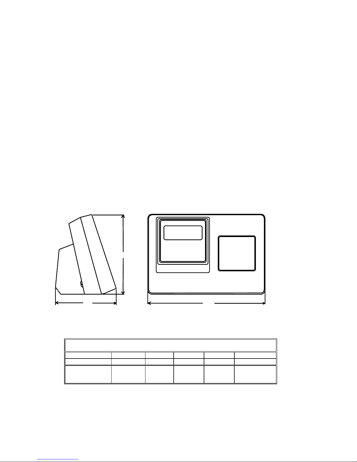
1.2.5 Physical Dimension
324
204
168
METTLER TOLEDO
8142PRO
0
1000
1.3 Ordering Information
8142Pro+ MODEL CONFIGURATION
ex: PRGN-0038-023
PRGN X X X X XXX
MODEL PCB type Reserved Market DISPLAY Country
PR - 8142Pro+
G-General housing
N - Numeric
1 - Analog L/C
2 - HAP
0 3- Export 7 - Single
8 – Dual
023 - CHINA
3
2. Installation
This chapter gives detailed instructions and important information you will need to install 8142Pro+ scale
instrument successfully. Please read this chapter throughly before you begin installation.
2.1 Unpacking and Inspection
Please inspect the package as it is delivered by the carrier. If the shipping container is damaged, check for
internal damage and file a freight claim with the carrier if necessary.
If the container is undamaged, unpack the 8142Pro+ scale instrument from its protective package, noting
how it was packed, and inspect each component for damage.
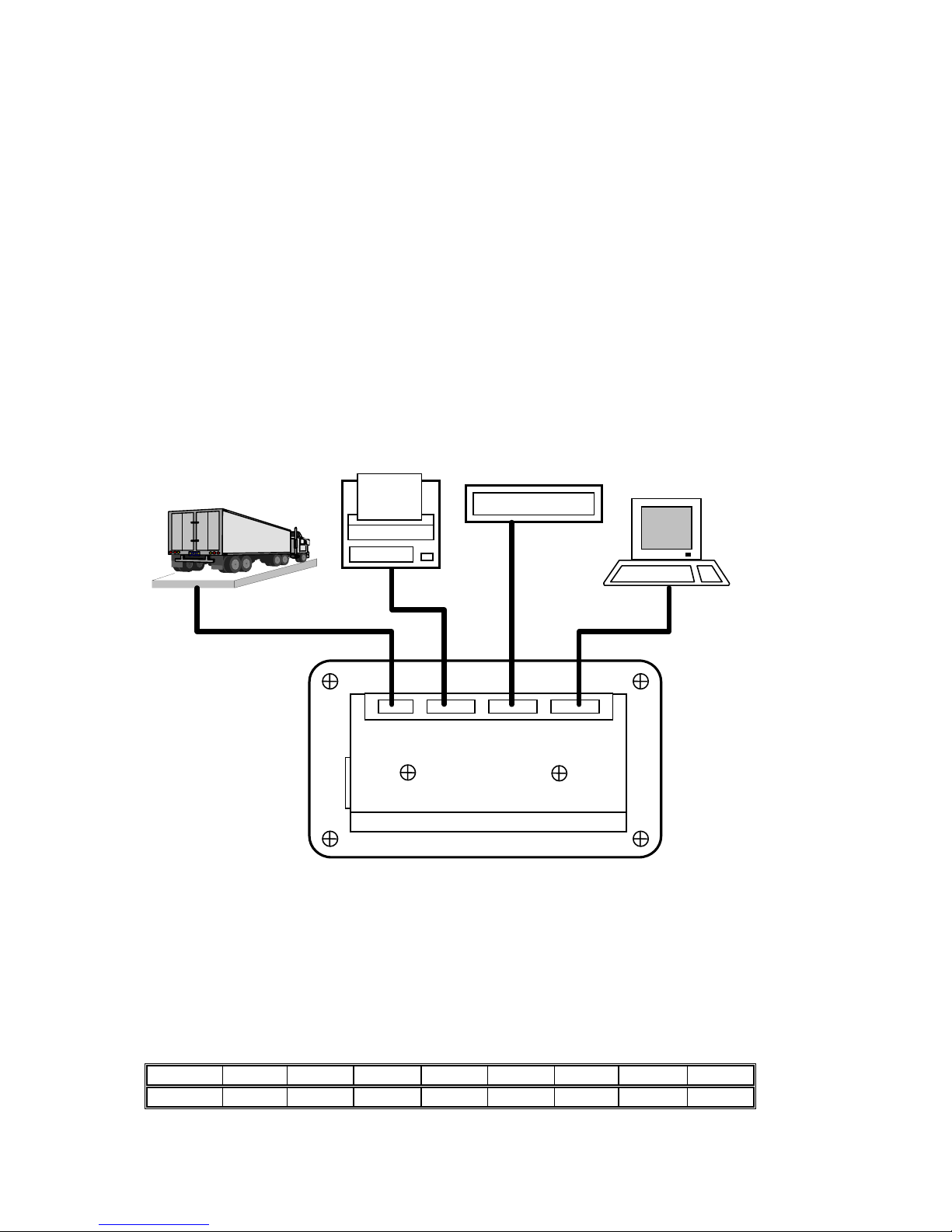
2.2 Electrical Connections
ScaleWin
计 算 机
IBM
LOAD CELL COM1
COM2
PARALLEL
Power Cord
1000 kg
Platform Scale
Scoreboard
Printer
8142PRO PR8 Terminal
1 1500 500 1000
PQ30
1
1
1
1
Computer
2.2.1 Connect the Load Cell
8142Pro+ powers up to eight 350Ω analog load cells.
The wiring between 8142Pro+ and junction box is standard 6-wire cable
The analog load cell connector to the terminal is a 9 pin D-SUB female connector. The following diagram
shows the pins assignments for 9 pin D-SUB connector. (Pin 9 is used to connect to the outer shield layer of
cable)
SIGNAL +EXC +SEN SHLD -SEN -EXC +SIG -SIG GND
PIN 1 2 3 4 5 7 8 9
4
2.2.2 Serial Port COM1 Connection
The serial port COM1 consist of RS-232 and 20 mA current loop.
The maximum recommended cable length for RS-232 interface is 50 feet.
The maximum recommended cable length for 20 mA interface is 1000 feet.
The serial port COM1 connector is a 25 pin D-SUB female connector. The following diagram shows the pins
assignments for COM1 connector.
SIGNAL PIN
SHIELD GROUND 1
TXD (RS-232) 2
RXD (RS-232) 3
SIGNAL GROUND 7, 19, 22, 23
CLRX+ 8, 16
CLTX+ 9
CLRX- 10, 18
Note: The transmitter of 20 mA current loop is active, the receiver is passive.
Below is the pin assignment of 8142Pro+ 8 to the Mettler-Toledo scoreboard .
COM1 at 8142Pro+ 7 Mettler-Toledo Scoreboard
9 1 CLRX+
7 2 CLRX-
If you want to connect your 8142Pro+ 8 to the computer , please refer to the below sheet for pin assignment .
COM1 Computer ( 9 pin ) Computer ( 25 pin )
2 2 3
3 3 2
7 5 7
2.2.3 Serial Port COM2 Connection
The serial port COM2 consist of RS-232 and RS-422.
The maximum recommended cable length for RS-232 interface is 50 feet.
The maximum recommended cable length for RS-422 interface is 2000 feet.
The serial port COM2 connector is a 25 pin D-SUB female connector. The following diagram shows the pins
assignments for COM2 connector.
SIGNAL PIN
SHIELD GROUND 1
TXD (RS-232) 2
RXD (RS-232) 3
SIGNAL GROUND 7
TXD+ (RS-422) 11
5
TXD- (RS-422) 12
RXD+ (RS-422) 13
RXD- (RS-422) 24
2.2.4 The Parallel Interface
The parallel interface is standard Centronics printer interface. It is used to connect to a printer.
The parallel port connector is a 25 pin D-SUB female connector. The following diagram shows the pins
assignments for connector.
SIGNAL PIN SIGNAL PIN
STRORE 1 BUSY 11
DATA BIT0 2 PAPER EMPTY 12
DATA BIT1 3 SELECT 13
DATA BIT2 4 AUTO FEED 14
DATA BIT3 5 ERROR- 15
DATA BIT4 6 INIT- 16
DATA BIT5 7 SELECT- 17
DATA BIT6 8 SIGNAL GND 18 ~ 25
DATA BIT7 9
ACK- 10
2.3 8142Pro+ Jumper and Switch Settings
Jumper and switches on the main PCB should be set as follows:
• K1-1 is the setup enable switch. This switch should be ON to access all setup parametersand be OFF in
operating mode .
• K1-2 is selection switch for comma. This switch should be ON to display comma (not decimal point).
• K1-3 is used to access factory test mode. This switch is always OFF in the normal operation mode.
• K1-4 is used to access factory test mode. This switch is always OFF in the normal operation.
• W1 jumper should be removed for 3 mV/V, installed for 2 mV/V analog load cell.
2.4 Minimum Increment Size for Analog Scale Input
The minimum increment size selection for an analog scale input is determined by calculating the microvolts
per increment for the desired build.
2.4.1 Solve the following equation for µV per increment.
Increment Size x cell output x excitation voltage (15) x 1000
µV per Increment = ---------------------------------------------------------------------------------
Load Cell Capacity x Number of Cells or Level Ratio
The increment size, scale capacity, and load cell capacity must all be measured in the same weight units, lb
or kg.
6
Load cell output is rated in mV/V (millivolts per volt of excitation), marked on load cell data tag. Mettler
Toledo load cells are typically 2 mV/V. Other load cells can range from 1 mV/V to 4.5 mV/V.
The load cell capacity is the rated capacity marked on load cell data tag. The number of cells is the total
number of load cells in the system , for the electronic –mechanical scale , the level ratio is the total level
ratiop in the system .
2.4.2 Calculate the total number of increments by dividing the calibrated capacity by the
increment size.
Calibrated Capacity
# Increments = ----------------------------
Increment Size
2.4.3 Microvolt build table
Use the following microvolt build table to determine if the µV per increment calculated in step 1 is within
the range allowed for the total number of increments calculated in step 2. These parameters have
demonstrated stable builds but smaller minimum µV per increment and larger total number of increments are
possible.
Microvolt Build Table
Total
Number of
Increment
Minimum
µV per
Increment
Maximum mV per Increment
2 mV/V 3 mV/V
1,000 3.0 26.0 38.0
2,000 1.5 13.0 19.0
2,500 1.2 10.4 15.2
3,000 1.0 8.7 12.7
4,000 0.75 6.5 9.5
5,000 0.6 5.2 7.6
6,000 0.5 4.4 6.4
8,000 0.375 3.3 4.8
10,000 0.3 2.6 3.8
20,000 0.15 1.3 1.9
50,000 0.1 0.52 0.76
Note: 8142Pro+ should never be programmed for least than 0.5 µV per increment when used with single
load cell applications and never less than 0.1 µV per increment when used with multiple load cell
applications. 8142Pro+ cannot be calibrated for builds that exceed the maximum µV per increment listed in
the microvolt build rate.
3. 8142Pro+ Operations
This chapter provides information that an operator will need to become fimiliar with the terminal and to
perform its functions.
7
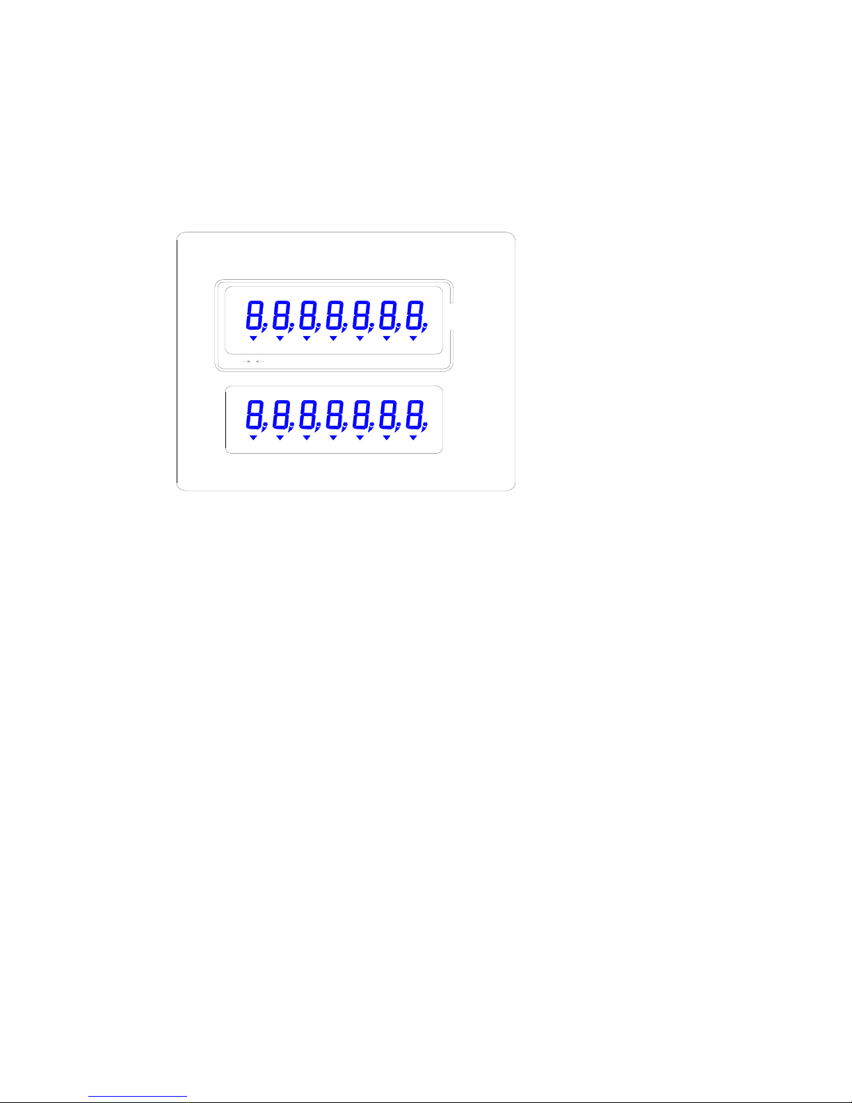
3.1 8142Pro+ Display and Keyboard
8142Pro+ dual display version has two displays where scale data and operational message are presented. These are
pictured below:
The two displays are same. The display is a numeric display. This area can display up to seven numbers each
with a decimal point, comma, and annunciators. The annuniciators are:
• Center-of-zero (→ o ← )
The center-of-zero annunciator indicates that the scale is within ± ¼ increment of gross zero.
• Scale in-motion ( ~ )
The scale instability annunciator indicates that the scale is in motion. The annuniciator will turn off when the
scale is stable. The motion sensitivity of motion detection is adjustable in setup.
• Weighing mode ( Gross or NET)
The 8142Pro+ will be in Net mode when a tare is active. Tare can be entered as a Preset tare value or tare
may be automatically acquired when the operator presses the TARE key.
• Consecutive Number ( CN )
The consecutive number annunciator indicates CN has been recalled and displayed. You can exit the recall
mode of CN by pressing EXIT key.
• Truck ID
The truck ID annunciator indicates that you are entering a truck identification.
• TARE
The tare annunciator indicates a pushbutton tare or keyboard tare is active.
• TIME/DATE
The time annunciator indicates TIME has been displayed. The date annunciator indicates DATE has been
displayed.
• Accumulator (Accum.)
The accumulator annunciator indicates accumulation has been recalled and displayed. You can exit the
recall mode of accumulation by pressing EXIT key.
ID
Cargo C lient
ID
Accum. ReportDate
Time
Tare
ID
GNetCN
Truck
0
~
Kg
8
• Cargo ID
The cargo ID annunciator indicates that you are entering a cargo identification.
• Client ID
The client ID annunciator indicates that you are entering a client identification.
• Report
The report annunciator indicates that the scale is in report mode.
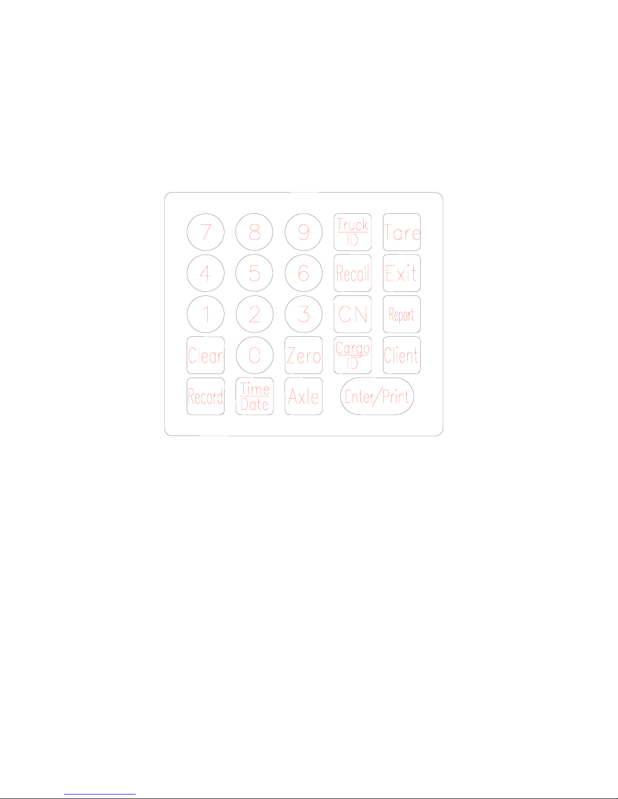
8142Pro+ dual display version is equipped with a 24-key keypad as seen below:
The keypad consists of numeric keys 0 through 9 and fourteen function keys.
The keys perform the following functions:
• NUMERIC keys are used to input numbers.
• ZERO zeros the scale. The ZERO key also functions as backspace when entering data from the keypad.
• TARE performs a pushbutton tare or keyboard tare if enabled in setup.
• CLEAR clears a tare value and returns the scale to gross mode. The CLEAR key also functions as
delete when entering data from the keypad.
• Truck ID acknowledges a prompt and accepts data as truck ID entered from the keypad.
• Cargo ID acknowledges a prompt and accepts data as cargo ID entered from the keypad.
• Client ID acknowledges a prompt and accepts data as client ID entered from the keypad.
• CN key is used to recall consecutive number.
• RECALL is used to recall consecutive number or accumulations.
• TIME/DATE key is used to enter or recall the clock and the date.
• REPORT can generate and print truck-related, cargo-related and client-related reports.
• RECORD key is used to store a weighing transaction.
• ENTER/PRINT acknowledges a prompt and accepts data entered from the keypad. It also initiates a
demand print output.
 Loading...