

Mettler Toledo 8132 Service Manual

8132
Indicator
Service Manual
TM008132I06

INTRODUCTION
This publication is provided solely as a guide for individuals who have
received METTLER TOLEDO Technical Training in servicing the
METTLER TOLEDO product.
Information regarding METTLER TOLEDO Technical Training may be
obtained by writing to:
METTLER TOLEDO
Training Center
P.O. Box 1705
Columbus, Ohio 43216
(614) 438-4400
METTLER TOLEDO RESERVES THE RIGHT TO MAKE
REFINEMENTS OR CHANGES WITHOUT NOTICE.
i
PRECAUTIONS
CAUTION
• • READ this manual before operating or servicing this
equipment.
• • ALWAYS REMOVE POWER and wait at least 30
seconds BEFORE connecting or disconnecting any
internal harnesses. Failure to observe these
precautions may result in damage to, or destruction of
the equipment.
• • ALWAYS take proper precautions when handling static sensitive devices.
• • DO NOT connect or disconnect a load cell scale base
to the equipment with power connected or damage
will result.
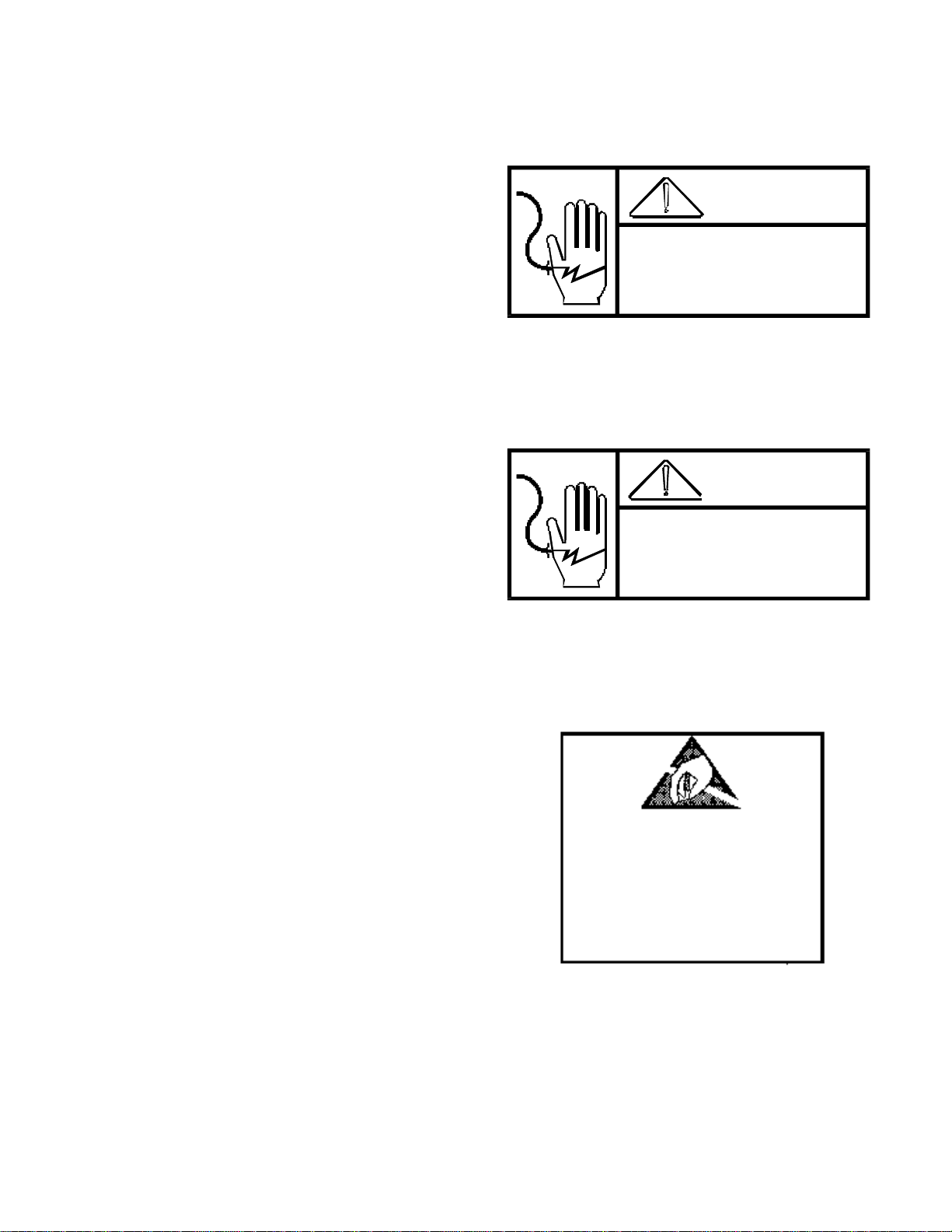
WARNING
DISCONNECT ALL POWER
TO THIS UNIT BEFORE
REMOVING THE FUSE
OR SERVICING.
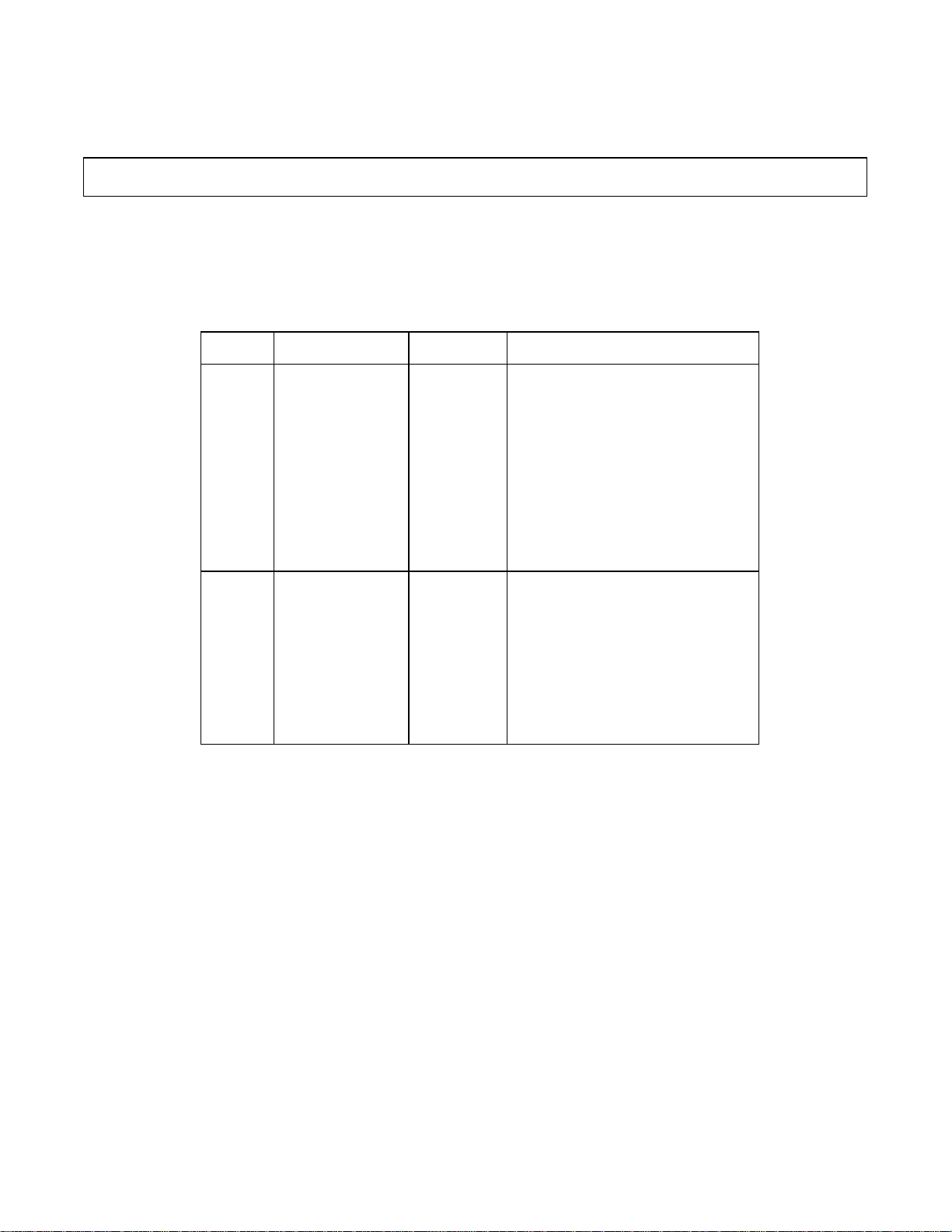
WARNING
ONLY PERMIT QUALIFIED PERSONNEL TO
SERVICE THIS EQUIPMENT. EXERCISE CARE
WHEN MAKING CHECKS, TESTS, AND
ADJUSTMENTS THAT MUST BE MADE
WITH POWER ON.
• • SAVE this manual for future reference.
• • DO NOT allow untrained personnel to operate, clean, inspect, maintain, service, or tamper with this
equipment.
• • ALWAYS DISCONNECT this equipment from the power
source before servicing.
OBSERVE PRECAUTIONS
FOR HANDLING
• • CALL METTLER TOLEDO for parts, information, and
service.
ELECTROSTATIC
SENSITIVE DEVICES
ii

Contents
1. GENERAL DESCRIPTION................................ ................................ ................................ ............................. 1
2. SYSTEM DESCRIPTION................................ ................................ ................................ ................................ 2
2.1 THE 8132 CONSISTS OF THREE (3) MAJOR BLOCKS: ................................ ................................ ......... 2
2.2 THE 8132 SETPOINT UNIT RETAINS ALL THE BASIC FUNCTIONS EXCEPT: ................................ ..... 2
3. SPECIFICATIONS................................ ................................ ................................ ................................ .......... 3
3.1 ELECTRICAL AND PHYSICAL SPECIFICATIONS................................ ................................ ................... 3
3.2 INTERNAL FUNCTIONS ................................ ................................ ................................ ........................... 3
3.3 DISPLAY FORMAT................................ ................................ ................................ ................................ .... 3
3.4 DATA INTERFACE................................ ................................ ................................ ................................ .... 4
3.5 FACTORY RAM IDENTIFICATION................................ ................................ ................................ ............ 4
3.6 RFI SPECIFICATIONS................................ ................................ ................................ ............................... 4
3.7 RAMS 9 AND 19 CUTOFF SPECIFICATIONS................................ ................................ ........................... 5
3.8 8132 FACTORY NUMBERS................................ ................................ ................................ ...................... 5
4. INSTALLATION INSTRUCTIONS................................ ................................ ................................ .................. 6
4.1 SET-UP PROCEDURE ................................ ................................ ................................ .............................. 6
4.2 PRECALIBRATION OF THE INSTRUMENT USING A LOAD CELL SIMULATOR................................ . 11
4.3 CALIBRATING THE 8132................................ ................................ ................................ ........................ 12
4.4 PROGRAM SWITCH SUMMARY (INCLUDING OPTION PCB'S)................................ ............................ 13
5. OPERATING INSTRUCTIONS................................ ................................ ................................ ..................... 32
6. PREVENTIVE MAINTENANCE................................ ................................ ................................ ..................... 37
6.1. REQUIRED TOOLS AND SUPPLIES ................................ ................................ ................................ ..... 37
6.2 MAINTENANCE SCHEDULE ................................ ................................ ................................ ................... 37
6.3 CLEANING ................................ ................................ ................................ ................................ .............. 37
6.4 TROUBLESHOOTING................................ ................................ ................................ ............................. 37
6.5 INPUT/OUTPUT CONNECTIONS................................ ................................ ................................ ............ 42
6.6 DATA OUTPUT TABLES ................................ ................................ ................................ ....................... 53
6.7 INTERCONNECT DIAGRAM................................ ................................ ................................ .................. 55
6.8 RECOMMENDED LIST OF SPARE PARTS................................ ................................ ........................... 58
6.9 8132 MAIN PCB CHART................................ ................................ ................................ ......................... 59
7. INTERFACE K.O.P.'S ................................ ................................ ................................ ................................ ... 60
7.1 PARALLEL I/O K.O.P................................. ................................ ................................ ............................. 60
7.2 EIA INTERFACE K.O.P. ................................ ................................ ................................ .......................... 60
7.3 MULTIPLE BUILD K.O.P. (151)................................ ................................ ................................ ............... 60
7.4 8820/30 PRINTER INTERFACE K.O.P.'S................................ ................................ ................................ 61
8. PARTS CATALOG................................ ................................ ................................ ................................ ........ 64
8.1 FRONT PANEL & COVER ASSEMBLY (DESK)................................ ................................ ..................... 64
8.2 MISCELLANEOUS HARDWARE (DESK)................................ ................................ ................................ 65
8.3 TRANSFORMER & HARNESS ASSEMBLIES (DESK)................................ ................................ ........... 66
8.4 INTERNAL HARDWARE (DESK)................................ ................................ ................................ ............. 67
8.5 FRONT PANEL & KEYBOARD (DESK AND WALL)................................ ................................ .............. 68
8.6 DISPLAY PCB & COMPONENTS................................ ................................ ................................ ............ 69
8.7 FRONT PANEL & MISCELLANEOUS HARDWARE (WALL)................................ ................................ . 70
8.8 DISPLAY ASSEMBLY (WALL)................................ ................................ ................................ ................ 72
8.9 OPTIONAL PCB'S & HARNESS (WALL)................................ ................................ ................................ 73
8.10 MISCELLANEOUS HARDWARE (WALL)................................ ................................ .............................. 74
8.11 MAIN PCB’S................................ ................................ ................................ ................................ .......... 75
8.12 COMMON C.O.D. MAIN PCB’S AND ADDITIONAL PARTS................................ ................................ . 76
8.13 INTERFACE K.O.P.’S................................ ................................ ................................ ............................ 77
8.14 SERIAL OUTPUT INTERCONNECTING CABLES................................ ................................ ................ 82
iii

1
1. GENERAL DESCRIPTION
The Model 8132 Electronic Digital Indicator is intended for use with strain gauge load cell scales. The
8132 provides Gross or Net weight and Tare weight displays. The unit is available in Desk and Wall
mount enclosures. Weight information is transmitted to a printer or accessory device using ASCII Code,
20 mA current loop, with even parity. The baud rate is selectable at 300, 1200, 2400, or 4800 Baud. An
8130 type output, Parallel BCD, is also available as an option. Other options include an Analog Over
PCB, an Analog Verification PCB an EIA interface (RS-232-C), setpoint output, and remote input PCB.
FEATURES
-- Selectable increments from 1000, 1500, 1700, 2000, 2500, 3000, 3400, 4000, 5000,
6000, 6800, 8000, 8500, 10,000, 12,000, 16,000, 17,000, and 20,000.
-- Displays Gross, net or Tare weight in pounds (LB) or kilograms (KG).
-- Continuous tare display.
-- Single or double width printing of displayed data, 0.3" high LED tare display.
-- Available in a desk mount enclosure or in a wall mount, NEMA 4, "washdown"
enclosure.
-- Power input is through a separate line cord.
-- Push-button tare or keyboard tare.
-- Computer compatibility.
-- Automatic Zero Maintenance (within ± 2% of scale capacity from zero).
-- Push-button zeroing (within ± 2% of scale capacity from zero).
-- Under capacity blanking at 7% of scale capacity.
-- Over capacity blanking at 5 increments over scale capacity.
Optional version of the 8132 (Rams 9 and 10) will provide TTL level control signals for two different
types of operations: however, both modes cannot be used at the same time. The two operations
include:
-- Either one or two cutoffs complete with dribble, preact and tolerance settings.
-- From one to four setpoints for use a single cutoffs. No dribble, preact or
tolerance values can be set.
The 8132 setpoint control signals will change states when the absolute value of the displayed weight
equals or exceeds the programmed setpoint value. This means that as long as the weighing sequence
starts at zero, the cutoffs can be used in either weigh up or weigh down mode.
With the Setpoint option, any time power is lost, all information is cleared to zero in the registers.

2
2. SYSTEM DESCRIPTION
The instrument provides 15 volts of excitation for strain gauge load cells. The excitation is gated so that
zero drift and temperature change can be compensated. The instrument conditions the microvolt signal
and amplifies it to a maximum level of about 10 volts. It is then filtered and converted to a digital signal
in the integrator.
The excitation voltage is 15 volts DC gated, switchable to 10 volts gated.
The initial range is adjustable from 0 to 30 millivolts.
The span range is adjustable from 3 to 30 millivolts.
The largest increment is 200 LB the smallest is 0.0001 LB.
Excitation current is provided for 6-240 ohm cells or 8-350 ohm cells.
2.1 THE 8132 CONSISTS OF THREE (3) MAJOR BLOCKS:
2.1.1 Control PCB -- Contains the scale logic, regulated strain gauge supply, program selection
switches and data transmission circuitry.
2.1.2 Display PCB -- Contains the weight, tare and legend LED's as well as the decoding
circuitry for the LED's and used as an interface for the keyboard.
2.1.3 Keyboard -- The keyboard allows operator interface for functions such as Tare, Print,
Clear,
LB/KG selection, push-button Zero and if ordered, Analog Verify. Test VERIFY and
Setpoint
information.
2.2 THE 8132 SETPOINT UNIT RETAINS ALL THE BASIC FUNCTIONS EXCEPT:
(of a standard 8132)
2.2.1 Keyboard switching from LB to KG is disabled; however, the unit may be powered up in
either KG or LB as determined by an internal programming switch.
2.2.2 Analog Verification is deleted and the program switch that was used for operation of AV
is now used for setpoint mode selection.
2.2.3 Display Verification has also been removed.
2.2.4 Several keys on the keyboard have a dual function such as entering tare and also
setpoint information.
2.2.5 Setpoint may be changed while the scale is in motion.

3
3. SPECIFICATIONS
8 8 8 8 8 8 88888
3.1 ELECTRICAL AND PHYSICAL SPECIFICATIONS
3.1.1 ENVIRONMENT
The Model 8132 operates from -10 C (14 F) to +50 C (122 F) 10 to 05% relative humidity, noncondensing.
Zero Temperature Coefficient -- 0.1 uV/ C Max.
Span Temperature Coefficient - ±12 PPM/ C Max.
3.1.2 POWER INPUT
The Model 8132 can operate (upon selection) at 100V, 120V, 220V and 240 VAC, (+10%, -15%) 49
Hz to 61.2 Hz. Power consumption is about 25 watts.
3.1.3 U.L. & C.S.A. STANDARDS
Materials, components and electrical design comply with U.L. and D.S.A. standards and
requirements, including grounding of all metal parts, fusing, etc.
3.1.4 APPEARANCE AND DIMENSIONS
The color of the Model 8132 is charcoal with a red display lens and color coded function
switches. The desk mount sheet metal enclosure is 8.8 cm tall (3.47"), x 43.2 cm wide (17"), x
23.7 cm deep (9.3"), suitable for rack mounting with adapters. The wall mount Stainless Steel
NEMA 4 enclosure is 33 cm high (13"), x 45.7 cm wide (18"), x 14 cm deep 5.5").
The desk mount model weights approximately 7 KG (15.4 LB), the wall mount unit weighs about
16 KG (35 LB).
Power, load cell and output connections are made via rear mounted connectors on the desk
Model 8132, and via connectors on the bottom of the NEMA 4 enclosure.
3.2 INTERNAL FUNCTIONS
The 8132 contains the necessary electronics, except the load cell (s), to calculate and display
weight, as well as the capability to transmit data to a remote device.
3.3 DISPLAY FORMAT
The weight display is 6 digit including (-) sign, 7 segment LED's.
The tare display is a 5 digit , 7 segment LED display. LED's are also used as a legend indicators.
Sample display:
On rams 9 and 19, the tare display is used to show what information is being entered for
setpoints. Once Setpoint Selection Mode has been entered and a location selected the tare
display will blink on and off displaying the data already stored. If no information is in that
location, the tare display will blink all zeros. When the new data has been entered the display
will return to displaying tare values.
4
3.4 DATA INTERFACE
Data output is provided in bit serial form, ASCII code, 20mA current loop, even parity. The baud rate is
selectable at 300, 1200, 2400, or 4800 baud.
NOTE: The PRINT push-button on the 8132 is NOT active when using the parallel BCD option with a
Model 500, 510 or 8895 Printer.
The 300 baud output is not changed with rams 0 and 19. The 4800 baud rate format changes to include
the status of setpoint, dribble, preact and tolerance.
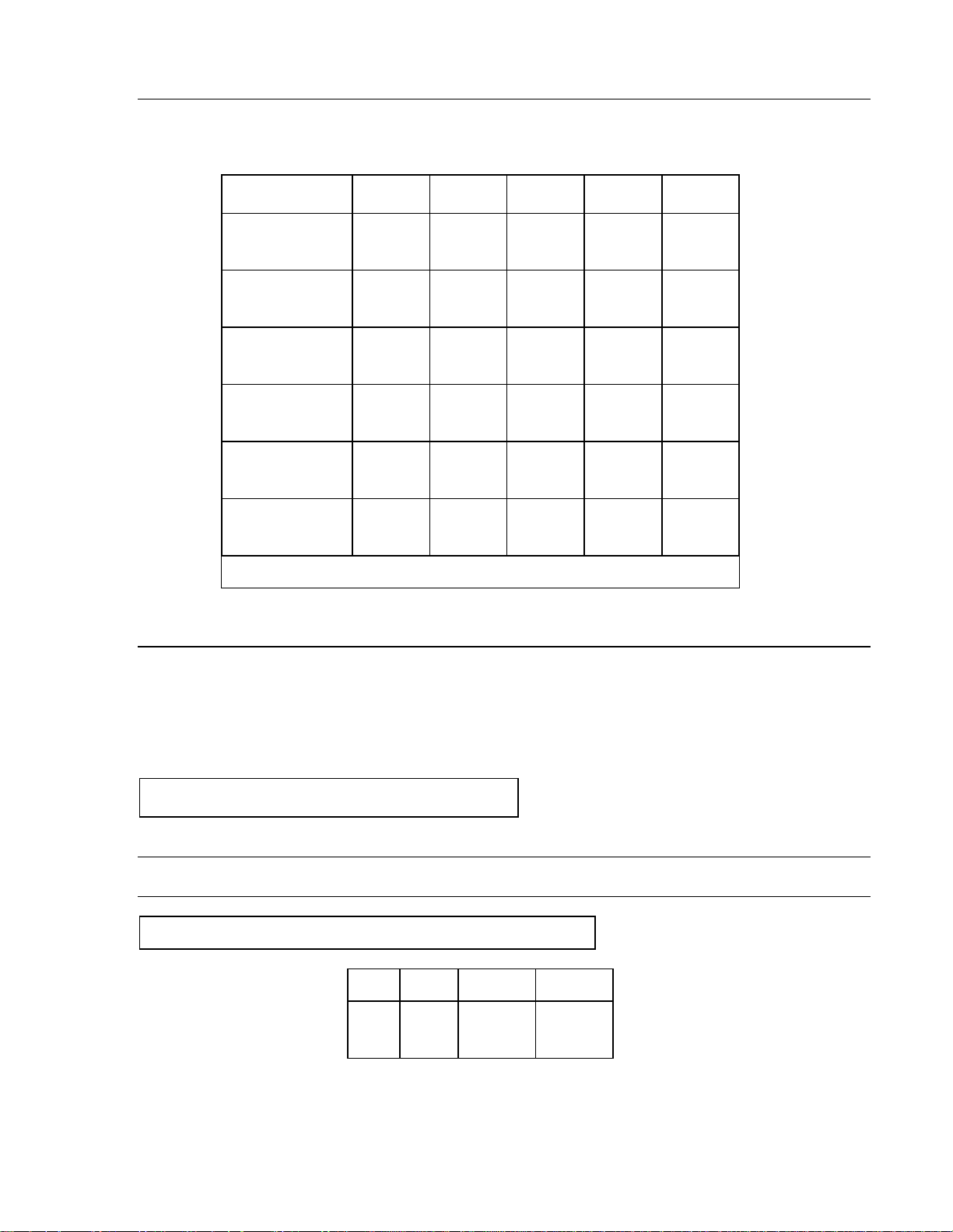
3.5 FACTORY RAM IDENTIFICATION
TYPE RAM NUMBER VERIFIED DESCRIPTION OF MAIN PCB
DESK
TOP
WALL
8132 0001
8132 0002
8132 0003
8132 0004
8132 0007
8132 0008
8132 0009
8132 0010
8132 0201
8132 0202
8132 0203
8132 1009
8132 0011
8132 0012
8132 0013
8132 0014
8132 0017
8132 0018
8132 0019
81320 020
8132 0211
8132 1019
NO
YES
YES
NO
NO
NO
NO
NO
NO
NO
NO
NO
NO
YES
YES
NO
NO
NO
NO
NO
NO
NO
Span Temp. Coef. of 12 PPM/ C
Span Temp. Coef. of 6 PPM/ C
Span Temp. Coef. of 3 PPM/ C
Span Temp. Coef. of 6 PPM C
Expanded Zero capture
Print Interlock
Setpoint Mode
Intrinsic Safe
Averaging
Averaging Checkweigh
Averaging legal for Trade
Setpoint w/Intrinsic Safe
Span Temp. Coef. of 12 PPM/ C
Span Temp. Coef. of 6 PPM/ C
Span Temp Coef. of 3 PPM/ C
Span Temp Coef. of 6 PPM/ C
Expanded Zero capture
Print Interlock
Setpoint Mode
Intrinsic Safe
Averaging
Setpoint w/Intrinsic Safe
*NOTES:
Expanded Zero Capture -- Zero will automatically capture when the display returns to within ± 3
increments of zero. Intended for large capacity scales only.
Print Interlock -- After printing, the indication must return to within ±.25 increments of zero before
another print may be made.
Setpoint Mode -- Provides TTL level signals for either two cutoffs, complete with dribble and preact, or
four signal setpoints.
Intrinsic Safety -- Excitation voltage is reduced to ±3 volts.
3.6 RFI SPECIFICATIONS
The Model 8132 has successfully passed FCC regulation regarding the emission of RFI. The
8132 has also passed SMA requirements for susceptibility to RFI. Additional protection may be
required in severe RFI environments.

5
3.7 RAMS 9 AND 19 CUTOFF SPECIFICATIONS
3.7.1 All cutoffs are TTL level negative true and "ON" when the displayed weight is less than
the programmed cutoff value. That is, the output is 0 volts unit the cutoff value. That is,
the output is 0 volts until the cutoff is reached then goes to a + 5 volt level.
3.7.2 The output consists of TTL open collector lines with 10K ohm pull-up resistors.
3.7.3 Each output will support 30 TTL loads of 7406 or similar gates.
3.8 8132 FACTORY NUMBERS
TYPE PART NUMBER VERIFIED DESCRIPTION OF MAIN PCB
DESK TOP
WALL
8132 0001
8132 0002
8132 0003
8132 0004
8132 0007
8132 0008
8132 0009
8132 0010
8132 0201
8132 0202
8132 0203
8132 1009
8132 0011
8132 0012
8132 0013
8132 0014
8132 0017
8132 0018
8132 0019
8132 0020
8132 0211
8132 1019
NO
YES
YES
NO
NO
NO
NO
NO
NO
NO
NO
NO
NO
UES
UES
NO
NO
NO
NO
NO
NO
NO
Span Temp. Coef. of 12 PPM/ ºC
Span Temp. Coef. of 6 PPM/ ºC
Span Temp. Coef. of 3 PPM/ ºC
Span Temp. Coef. of 6 PPM/ ºC
Expanded Zero Capture
Print Interlock
Setpoint Mode
Intrinsic Safe
Averaging
Averaging Checkweigh
Averaging Legal for Trade
Setpoint w/Intrinsic Safe
Span Temp. Coef. of 12 PPM/ ºC
Span Temp. Coef. of 6 PPM/ ºC
Span Temp. Coef. of 3 PPM/ ºC
Span Temp. Coef. of 6 PPM/ ºC
Expanded Zero Capture
Print Interlock
Setpoint Mode
Intrinsic Safe
Averaging
Setpoint w/Intrinsic Safe
6
4. INSTALLATION INSTRUCTIONS
4.1 SET-UP PROCEDURE
4.1.1 Inspect the indicator for loose or damaged parts.
4.1.2 Open the indicator and remove the top cover and continue the inspection, noting that all
the interconnecting harnesses are securely fastened.
4.1.3 Check the line filter/fuse holder assembly to insure that the proper voltage and fuse size
are selected for use in your area.
CAUTION: All units are shipped for 120 VAC operation. See below for alternate voltage
operation.
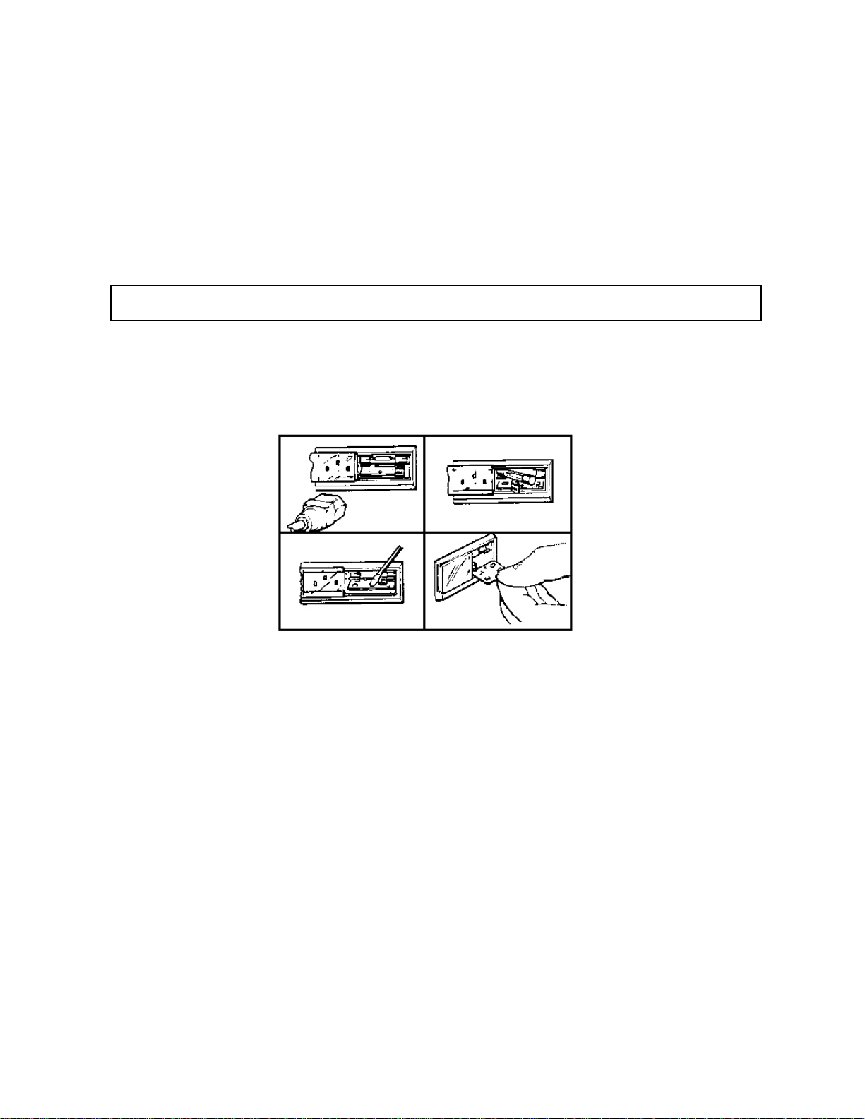
The following photos will assist you in checking or changing the voltage selection.
This step MUST be performed prior to applying power to the unit
1. This photo shows the line cord 2. In this photo the fuse is
detached and the fuse cover removed by pulling the handle
moved to the left. labeled “FUSE PULL”
3. With the fuse removed, 4. Once you have determined
use a small screwdriver or the proper voltage, return the
similar object and gently pry card to the slot. The voltage
the card from the assembly. desired will be on the left side
A hole in the card is provided of the card in a readable position.
to assist removal. In the photo, the voltage selected
is 120V. Replace the fuse with
one of the correct rating. Slide
fuse cover back into place.

7
4.1.4 Preliminary Calculations
Before any calibration is done it should be determined if the load cell (s) are of a size that
will work correctly with the instrument and platform. If it is a standard build, go ahead
and install the scale. However, if it is a special build or if it is a conversion of an existing
mechanical scale, it should be checked by determining the microvolts per increment then
checking it with the cart to make sure the proposed load cell (s) are the correct size.
HOW TO DETERMINE MICROVOLTS PER INCREMENT
FIRST FIND:
- Scale capacity*.
- Increment Size*.
- Number of load cells or total lever ratio.
- Size of load cell(s)*.
- Cell output rating in mV/V --millivolts per volt of excitation.
* In LB or KG depending on how scale is to be calibrated and used.
THEN:
1. Divide the scale capacity by the increment size to get the number of increments that the
indicator is to be programmed for.
2. Multiply the cell size by the number of cells or the lever ration (depending on the type of
scale). This will be the overall scale capacity (disregard initial at this time).
3. Divide the overall scale capacity by the increment size. This will be the overall number of
increments.
4. Multiply cell output in millivolts by 1,000 to get cell output in microvolts.
5. Divide cell output in microvolts by the overall number of increments to get microvolts per
increment.
NOTE: Load Cells built by Toledo are 2 mV/V. Load Cells built by BLH are usually 2 mV/V or 3 mV/V.
Load Cells built by HBM that are used on the Toledo 7200 are 1.8 mV/V. The Model 2300 is 1mV/V.
8
The chart below shows the limits in microvolts for each available number of increments.
MICROVOLT CHART
Number of Increments
Programmed
20,000
17,000
16,000
12,000
10,000
8,500
8,000
6,800
6,000
5,000
4,000
3,400
3,000
2,500
2,000
1,700
1,500
1,000
Maximum*
uV/ Increment
1.5
1.7
1.8
2.5
3
3.5
3.7
4.4
5
6
7.5
8.8
10
12
15
17
20
30
Minimum**
uV/ Increment
0.3
0.3
0.3
0.3
.0.3
0.35
0.37
0.44
0.5
0.6
0.75
0.8
1.7
2.0
3.0
1.7
2.0
3.0
NOTE: *the 8132 cannot be adjusted on builds that are greater than the voltage shown for maximum
V/ Increment.
NOTE: **the instrument should never be programmed to less than .3uV/ Increment for multiple cell
scales (4 or more) and no less than 1.5 V/Increment for single cell scales.
If these limits are exceeded, the scale will not be stable.
EXAMPLE 1
60 x 10 Bridgemaster
Scale Capacity in pounds......................................................................100,000 LB
Increment Size in pounds...............................................................................20 LB
Number of Load Cells..........................................................................................4
Size of Load Cells in pounds...................................................................100,000 LB
Cell Output Rating.......................................................................................2 mV/V
STEP 1
100,000 LB capacity -- 20 LB increments
100,000 ÷ 20 = 5,000 increments
STEP 2
4 load cells - 100,000 LB capacity
4 x 100K = 400,000 LB overall scale capacity
STEP 3
400,000 LB overall scale capacity -- 20 LB increments
400,000 ÷ 20 = 20,000 overall number of increments

9
STEP 4
2 mV/V cell output rating
STEP 5
30 mV x 1,000 = 30, 000 millivolts at full capacity
STEP 6
30,000 ÷ 20,000 = 3 ÷ 3 = 1.4 microvolt per increment
Check the Microvolt Chart to see if the V/Increment fits in the range listed for 5,000 increments.
The range listed is .6 to 6uV/Increment and 1.5 is inside this range, therefore, it will be a
satisfactory build.
Scale Capacity in pounds.......................................................................100,000 LB
Increment Size in pounds...............................................................................20 LB
Lever Ration..............................................................................................800 to 1
Size of Load Cells in pounds ..........................................................................200 LB
Cell Output Rating.........................................................................................mV/V
STEP 1
100,000 LB Capacity 0020 LB increments
2 mV/V x 15 - 30 millivolt cell output at full capacity
EXAMPLE 2
60 x 10 Lectrolever Scale
100,000 ÷ 20 = 5,000 increments
STEP 2
800 lever ratio -200 LB load cell
800 x 200 = 160,000 LB overall scale capacity
STEP 3
160,000 LB overall scale capacity - 20 LB increments
160,000 ÷ 20 = 8,000 overall number of increments
STEP 4
2mV/V output rating
2mM.V x 15 = 30 millivolt cell output at full capacity
STEP 5
30 mV x 1,000 = 30,000 microvolts at full capacity
STEP 6
30,000 ÷ 8,000 = 30 ÷8 =3.75 microvolts per increment
Check the Microvolt Chart to see if the V/ increments fits in the range listed for 5,000
increments. The range listed is .6 to 6 V/Increment and 3.75 V/Increment is inside the is range,
therefore, it will be a satisfactory build.

10
EXAMPLE 3
Model 2184
Scale Capacity in pounds...............................................................................300 LB
Increment Size in pounds..............................................................................0.01 LB
Lever Ratio............................................................................................... ..8.1 to 1
Size of Cell in pounds....................................................................................100 LB
Cell Output Rating........................................................................................2 mV/V
STEP 1
300 LB scale capacity --0.1 LB increments
300 ÷0.1 = 3.000 increments
STEP 2
8.1 lever ratio -100 LB load cell
8.1 x 100 - 810 LB overall scale capacity
STEP 3
810 overall scale capacity -0.1 LB increments
810 ÷ 0.1 - 8, 100 overall number of increments
STEP 4
2mV/V cell output rating
2mV/V x 15 = 30 millivolts at full capacity
STEP 5
30 mV x 1,000 = 30,000 microvolts at full capacity
STEP 6
30,000 ÷ 8.100 = 300 ÷ 81 = 3.7 microvolts per increment
Check the Microvolt Chart to see if the V/ Increment fits in the range listed for 3,000 increments.
The range listed is 1 to 10 V/Increment and 3.7 V/Increment is inside this range therefore, it will
be a satisfactory build.
4.1.5 Programming the 8132
a. Select the proper number of increments to match the capacity of the platform and
the load cell(s). Select with switches SW4-1 through SW4-5.
b. Select the proper increment size using switches SW5-2 and SW5-3.
c. Select the proper decimal point and/ or dummy zero (if used) with switches SW5-
9, SW 6-1, and SW6-2.
d. Select the proper functions for tare, KG/LB, printing and blanking with switches
remaining on SW5, SW6, and SW7.

11
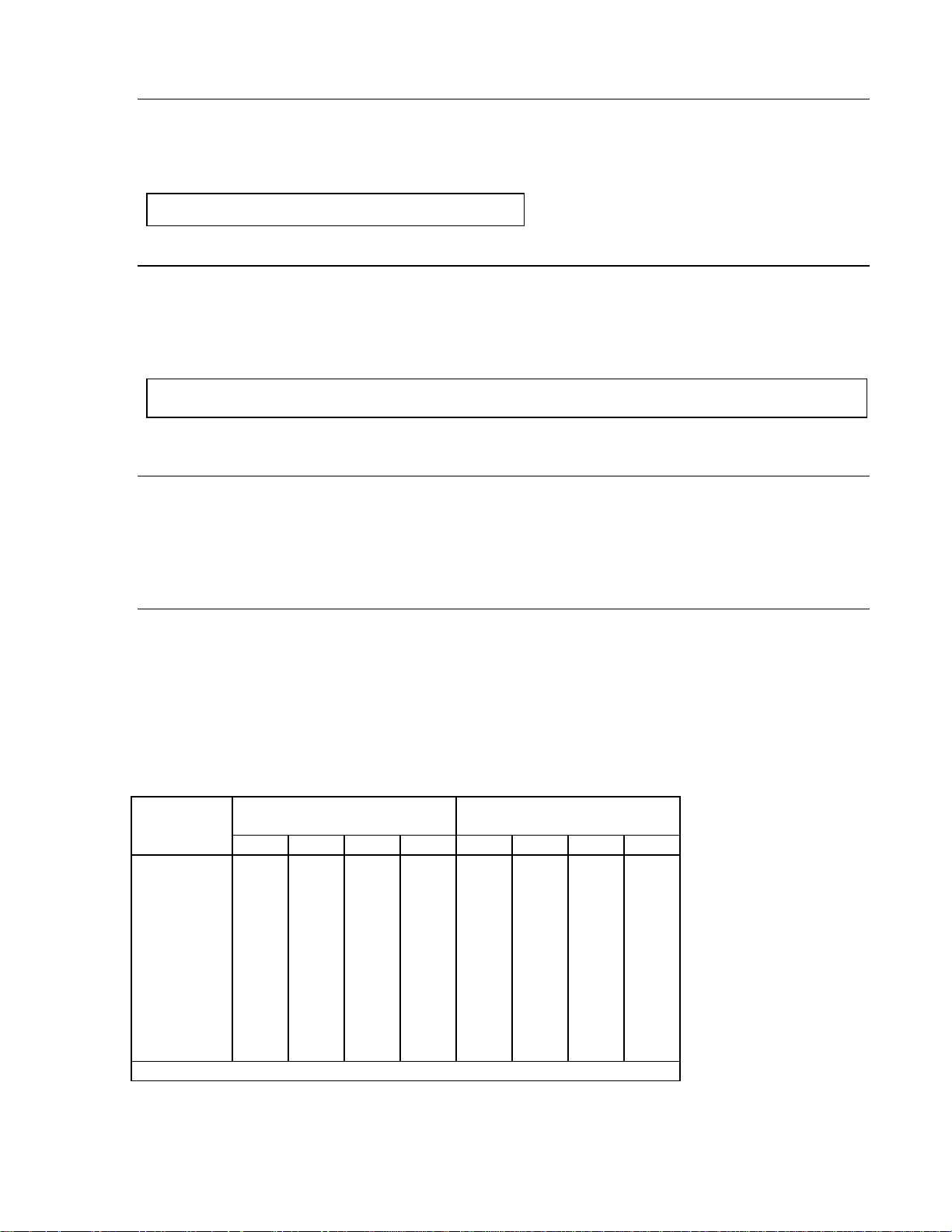
4.2 PRECALIBRATION OF THE INSTRUMENT USING A LOAD CELL SIMULATOR
NOTE: Precalibration of the 8132 is not a required step; however, it can reduce the number of times
test weights need to be applied to the scale platform.
FIRST FIND:
- Number of cells used.
- Capacity of one cell*.
- Total level ration (if required).
- Millivolt output of the cell(s).
* In LB or KG depending on how the scale is to be calibrated and used.
THEN:
1. Multiply the cell capacity by the number of cells used. Multiply this number by the lever
ratio, if required, to find the Total Cell Capacity.
2. Divide the Total Cell Capacity by the correct division number to find LB or KG per step on
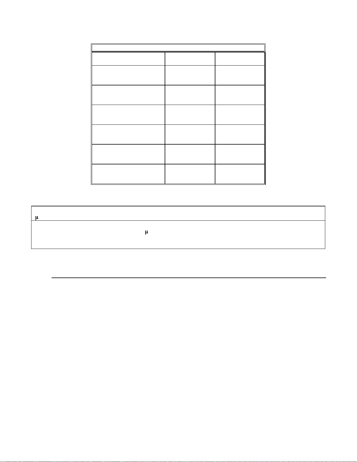
the simulator. Refer to the following chart for this number.
MILLIVOLTS/VOLT
CELL OUTPUT
1
1.8
2
3
3. At this time, connect the simulator to the instrument.
4. Connect to the power line.
5. Turn the simulator switch to the zero position and set the instrument to zero using the
initial switches and potentiometer.
6. Calibrate the instrument. Use the maximum number of steps on the simulator without
exceeding the instrument's capacity.
7. Remove power, disconnect the simulator from the instrument and connect the load
cell(s). Reconnect to power. At this time the display will indicate the initial weight. Rest
to zero using the initial switches and potentiometer. Make final calibration test with test
weights.
8. Record the indication at all steps on the simulator along with the simulator's serial
number. Attach this record to the instrument housing for future troubleshooting
assistance.
DIVISION
NUMBER
5
9
10
15
12
4.3 CALIBRATING THE 8132
4.3.1 Make sure the load cells are connected properly.
4.3.2 Turn SW7-1 ON before applying power or the indication will flash with the following
display. the zero pushbutton will not operate with SW7-1 ON.
E E E E E E
4.3.3 Turn initial potentiometer R-23 fully clockwise and span potentiometer R-24 fully
clockwise.
4.3.4 Start with SW1-1 through SW1-8 OFF, SW2-1 through SW2-7 ON and SW3-1 through
SW3-4 ON.
4.3.5 Zero the indication with the front panel zero adjustment.
4.3.6 Set span switch SW2-1 to the OFF position.
4.3.7 INITIAL -- To set initial, start with all SW1 switches OFF, then turn them ON, one at a time
starting with SW1- noting if it takes the indication below zero. If it does, turn OFF that
switch again and go to the next switch. Try turning SW1-2 through SW1-8 ON, one at a
time, only leaving the switches ON that do not take the indication below zero. SW1-1 will
be the largest step and will be used only on scales with very high initial. Make the final
initial adjustment with the fine initial potentiometer R-24.
4.3.8 SPAN-- When setting Span start with all SW2 and SW3 switches in the OFF position and
the indication reading zero. Place test weights on the platform. (Approximately 10% of
scale capacity.) Try turning SW2-1 ON. If the indication is too low, turn, that switch back
OFF and go the next switch. Turning On this switch will have 1/2 the effect of the
previous switch. Continue turning ON only the switches that do not take the indication
below the correct reading. Make the final span adjustment with the span potentiometer
R-24.
4.3.9 Remove test weights and check zero.
4.3.10 Repeat
steps 8 and 9
until scale is
calibrated
properly. The
display can be
expanded by
SW6-6 to allow
more accurate
calibration.
4.3.11 Remove
test weights
from the
understructure
and turn SW7-1
OFF. Capture
zero with the
zero button.

13
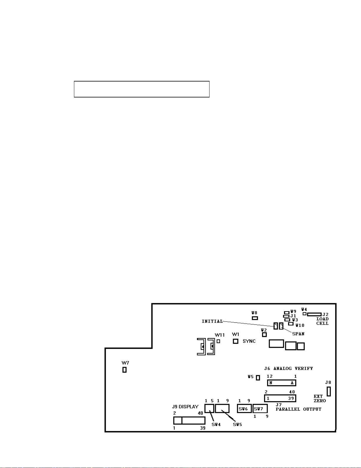
4.4 PROGRAM SWITCH SUMMARY (INCLUDING OPTION PCB'S)
It is important that you check the Technical Manual of the printer (if a printer is to be used), for program
switch settings that may affect printer operations and formats, prior to connecting your 8132 Digital
Indicator to the printer.
NOTE: The 8132 should never be programmed for a greater number of increments or a smaller
increment size than the scale understructure will allow. Each understructure has a list of standard
configurations (capacity and increment sizes) which should determine how the 8132 is to be
programmed.
4.4.1 ANALOG FILTER
An Analog Filter is provided with selectable response of 2 seconds and 3 seconds settling time.
The resistor pack (R72) can be inserted into its socket either of two ways- thus controlling the
Analog Filtering. R72 is located on the right edge of the PCB, (facing the instrument) about halfway back on the desk mount unit and the left for the wall mount unit.
For maximum filtering (3 seconds response) install resistor pack with number one pin or dot
away from load cell connector (J2).
For minimum filtering (2 seconds response) install resistor pack with number one pin or dot
toward the load cell connector (J2).
1 second and 5 second update rates are available by replacing the R72 resistor pack with the
specific resistor pack designated for either update rate. Refer to the 8132 Parts Catalog,
PC008132 I05, for the part numbers.

14
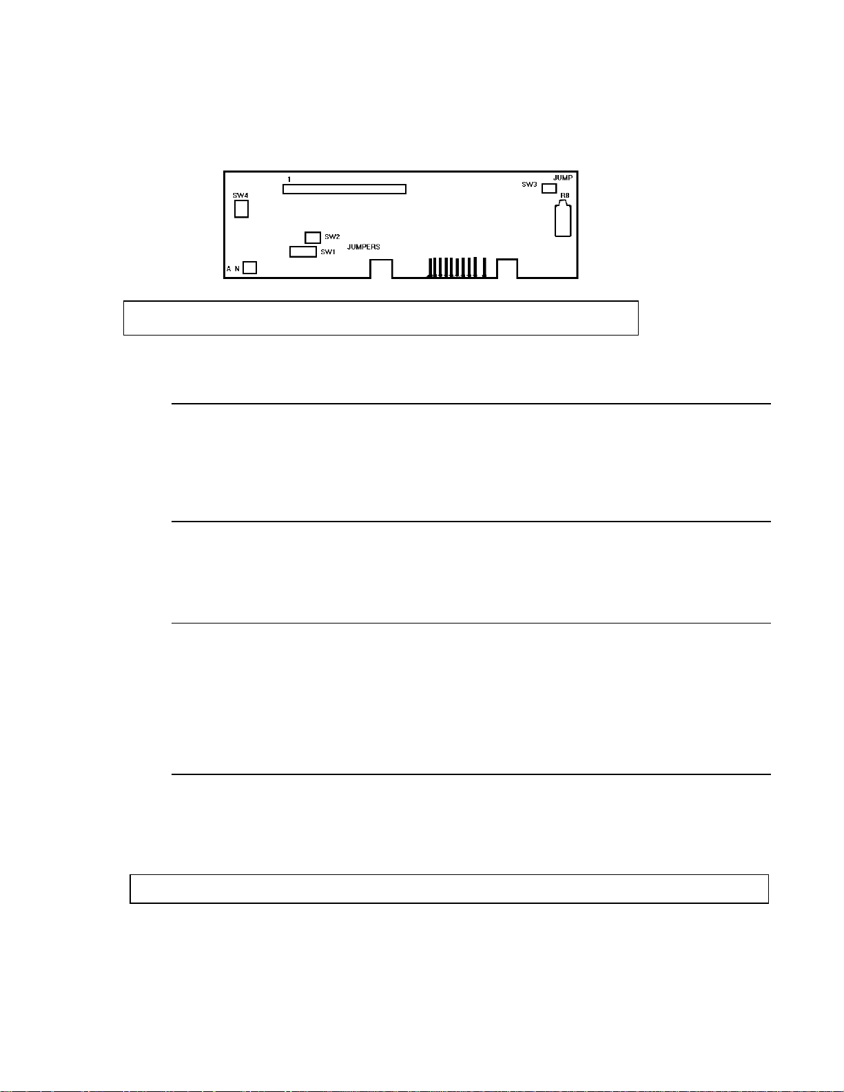
4.4.2 CONTROL PCB PROGRAM SWITCHES
TURNING ON ANY OF SW1 INITIAL SWITCHES WILL INCREASE THE INITIAL COMPENSATION.
SW1-2 HAS 1/2 THE EFFECT OF SW1-1.
SW1-3 HAS 1/2 THE EFFECT OF SW1-2, AND SO ON DOWN TO SW1-8.
SW1 --INITIAL
SW1-1 --LARGEST STEP
SW1-2 -SW1-3 -SW1-4 -SW1-5 -SW1-6 -SW1-7 -SW1-8 --SMALLEST STEP
SW1-9 --NOT USED
TURNING ON ANY OF SW2 AND SW3 SPAN SWITCHES WILL DECREASE THE WEIGHT
INDICATION.
SW2-2 HAS 1/2 THE EFFECT OF SW2-1.
SW2-3 HAS 1/2 THE EFFECT OF SW2-2 AND SO ON DOWN TO SW3-4.
SW2-1 --LARGEST STEP
SW2-2 -SW2-3 -SW2-4 -SW2-5 -SW2-6 -SW2-7 --
SW3
SW3-1 -SW3-2 -SW3-3 -SW3-4 --SMALLEST STEP
15
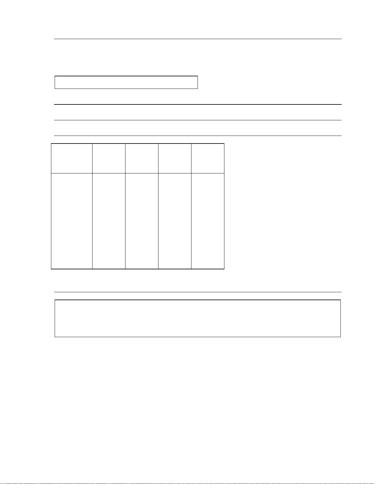
SW4-1 THRU SW4-5
After you have determined the required number of increments, use the chart to find the
appropriate switch settings.
NO. OF
INCREMENTS SW4-1 SW4-2 SW4-3 SW4-4 SW4-5
1000
1500
1700
2000
2500
3000
3400
4000
5000
6000
6800
8000
8500
10000
12000
16000
17000
20000
OFF
OFF
OFF
OFF
OFF
OFF
OFF
OFF
OFF
OFF
OFF
OFF
OFF
OFF
OFF
OFF
ON
ON
OFF
OFF
OFF
OFF
OFF
OFF
OFF
OFF
ON
ON
ON
ON
ON
ON
ON
ON
OFF
OFF
OFF
OFF
OFF
OFF
ON
ON
ON
ON
OFF
OFF
OFF
OFF
ON
ON
ON
ON
OFF
OFF
OFF
OFF
ON
ON
OFF
OFF
ON
ON
OFF
OFF
ON
ON
OFF
OFF
ON
ON
OFF
OFF
OFF
ON
OFF
ON
OFF
ON
OFF
ON
OFF
ON
OFF
ON
OFF
ON
OFF
ON
OFF
ON
NOTE: Use only the above switch settings.
SW5-1 LB/KG SELECTION INHIBIT
ON -The display will remain in either LB or KG, as selected by SW6-9 and cannot be changed
from one to the other.
OFF -The display may be changed from LB to KG and back again as desired.
RAMS 9 AND 19 ONLY
SW4-1 - Not Used - Should be OFF
SW5-2 INCREMENT SIZE
SW5-3 INCREMENT SIZE
NOTE: DO NOT LEAVE SW5-2 AND SW5-3 BOTH OFF.
LB. KG. SW5-2 SW5-3
X1
X2
X5
X0.5
X1
X3
OFF
ON
ON
ON
OFF
ON
16
SW5-4 TARE DISPLAY
ON -The Tare Display is OFF and Tare is inoperative.
OFF -The Tare Display is ON and the keys affecting tare are operative.
NOTE: SW5-4 must be OFF with Rams 9 & 19.
SW5-5 AUTO CLEAR
ON -Tare must be cleared by the use of the C (Clear) pushbutton.
OFF - Tare will automatically clear when the indication returns to zero. (The scale must first
settle at some weight value greater than 10 increments up scale.)
NOTE: SW5-4 must be OFF for this function to operate. Also see SW5-7 for possible
interaction.
SW5-6 MULTIPLE LINE PRINTING
ON -Single line printing.
OFF -The printer will print multiple lines -- Gross, Tare, and Net.
SW5-7 TARE INTERLOCK
ON -Tare may be cleared or changed at any positive weight indication. Keyboard entries
(both tare and setpoint) are rounded to the nearest increment size.
OFF -The indication must be at true zero before the tare can be removed. (True zero is
actually ZERO minus the tare value.) The least significant digit of keyboard entry (tare
and/or setpoint information) must correspond to the increments size or the entry will not
be accepted.
LSD OF
TARE WITH SW5-7 OFF WITH SW5-7 ON
ENTERED X1 X2 X5 X10 X1 X2 X5 X10
0
1
2
3
4
5
6
7
8
9
10
0
1
2
3
4
5
6
7
8
9
10
0
2
4
6
8
10
0
-
-
-
-
-
-
-
5
-
-
-
-
-
-
10
0
10
0
-
-
-
-
-
-
-
-
-
1
2
3
4
5
6
7
8
9
10
10
10
0
2
2
4
4
6
6
8
8
0
0
0
5
5
5
5
5
10
10
10
0
0
0
0
0
10
10
10
10
10
10
( - ) Tare not accepted.
17
SW5-8 TARE ENTRY
ON -Digital Tare will not work, pushbutton Tare does work.
OFF -Digital Tare and pushbutton Tare both work.
NOTE: SW5-8 must be OFF with Rams 9 & 19.
SW5-9 DECIMAL POINT
SW6-1 DECIMAL POINT
SW6-2 DECIMAL POINT
LB KG
X5
X2
X1
XXXX00
XXXXX0
XXXXXX
XXXXX.X
XXXX.XX
XXX.XXX
XX.XXXX
X.XXXXX
KG
X2
X1 KG.
X5 SW5-9 SW6-1 SW6-2
XXXXX0
XXXXXX
XXXXX.
X
XXXX.X
X
XXX.XX
X
OFF
OFF
OFF
OFF
ON
ON
ON
ON
OFF
OFF
ON
ON
OFF
OFF
ON
ON
OFF
ON
OFF
ON
OFF
ON
OFF
ON
XX.XXX
X
X.XXXX
X
----
SW6-3 AUTO ANALOG VERIFY/SETPOINT MODE SELECT
NOTE: In order for Analog Verification to operate, an Analog Verification PCB must be in
place in J6 on the 8132 Main PCB.
NOTE: Auto Analog Verify (SW6-3) must be OFF and Analog Verify (SW6-4 must also be on).
Analog Verification
ON -The Analog Verify will operate only when AV button is pressed. (SW6-4 must also be
On).
OFF -The Analog Verify will operate automatically every time the indicator reruns to
true zero. (The scale must firs settle at some weight value greater than 10
increments up scale.) The Analog Verify will also operate manually by pressing the AV
button while at true zero.
18
RAMS 9 AND 19 ONLY
SETPOINT MODE SELECT
If Rams 9 or 19 are used, SW6-3 is used to select the mode of operation.
ON -The four setpoint mode is selected with no dribble, preact or tolerance settings.
OFF -Two setpoints with dribble, preact and tolerances are selected.
NOTE: All setpoint information must be checked after changing
SW6-3.
SW6-4 ANALOG VERIFY
ON -Analog Verify will operate.
OFF -Analog Verify will not operate.
RAMS 9 AND 19 ONLY
SW6-4 -- Not Used -- Should be OFF
SW6-5 DEMAND MODE
ON -Normal mode, internal update is used.
OFF -Demand mode, the Demand Input line, (refer to Serial Connector Diagram) must be held
low, then pulsed positive at +5V for 50 ms, forcing an A/D cycle.
SW6-6 EXPAND (For Calibration Only)
ON -The display will be expanded for calibration.
INCREMENT
SIZE
1
2
5
OFF -Normal Mode.
NOTE: The AZM (Automatic Zero Maintenance) will be disabled in the expand mode. Check
zero after switching to expand.
SW6-7 MOTION SENSITIVITY
ON -2 increments or less of movement is not detected.
DISPLAY
EXPANDED BY
X10
X5
X2
OFF -1/2 increment or less of movement is not detected.

19
SW6-8 MOTION BLANKING
ON -Motion on the scale will NOT cause the display to blank.
OFF -Motion on the scale will blank the display. (Sensitivity is determined by SW6-7.)
SW6-9 POWER UP KG
ON -The display will be in KG when power is first applied. The Analog Verify option will
operate only in the Kg mode.
OFF -The display will be in LB when power is first applied The Analog Verify option will
operate in the LB mode only.
NOTE: This switch MUST be set BEFORE power is applied. Selection of LB or KG may be
made at the keyboard. (See SW5-1).
SW7-1 AUTOMATIC ZERO MAINTENANCE (AZM)
ON -AZM and the Z (Zero) pushbutton are disabled. The display will not blink on power up.
OFF -AZM will operate to keep the instrument on zero in spite of small changes on the
platform. (Less than 1 increment.) The Z (Zero) pushbutton will also operate.
SW7-2 CHECKSUM
ON -No Checksum character transmitted.
OFF -A Checksum character is transmitted to a device requiring checksum.
NOTE: Checksum is defined as the 2’s complement of the sum of the bits 0-6 of all characters
preceding the checksum character.
SW7-3 PRINT GROSS, TARE, NET
ON -The printer will print the Gross, Tare, and Net weight information.
OFF -Only the displayed weight is printed. (Gross or Net - Not Tare.)
SW7-4 -NEGATIVE WEIGH PRINTING
ON -Below “0” weights may be printed.
OFF -The printer will not print as long as the indication is below “0”.
20
SW7-5 PRINT TONS
ON -A symbol “t” for tons is printed in place of the LB or KG symbol.
OFF -Only the LB or KG units is printed.
NOTE: No conversion from LB or KG to tons is made. The scale MUST be calibrated in
tons.
The 8805 printer will not print a "t" for tons. The space for the weight symbol will be left blank if
SW7-5 is ON.
SW7-6 BAUD RATE SELECT
SW7-7 BAUD RATE SELECT
The setting of SW7-6 and SW7-7 will determine the output baud rate.
BAUD RATE SW7-6 SW7-7
300
1200
2400
4800
NOTE: At 300, 1200, and 2400 baud, activation of the PRINT pushbutton or a remote print
command is required to generate a transmission. At 4800 baud the output is continuous.
THE 8132 WILL OPERATE AT 300 BAUD OR 4800 BAUD ONLY!. WHEN INSTALLING
SW7-6 BAUD RATE SELECT (20 mA OUTPUT)
ON -The weight information is continuously transmitted at the 4800 Baud rate.
OFF -The weight information is transmitted at the 300 Baud rate. Activation of the PRINT
pushbutton or remote print command is required.
SW7-7 MINIMUM PRINT
SW7-8 MINIMUM PRINT
The setting of SW7-7 and SW7-8 determines how many increments must be displayed before a print
may be made.
INCREMENTS SW7-7 SW7-8
OFF
OFF
ON
ON
ONE OF THESE RAMS, THE SWITCH SETTINGS ARE AS FOLLOWS.
OFF
ON
OFF
ON
RAMS 9 AND 19 ONLY
0
10
20
50
OFF
OFF
ON
ON
OFF
ON
OFF
ON

21
SW7-8 MINIMUM PRINT
ON -There must be at least 20 increments displayed before a transmission will occur.
OFF -No Minimum
SW7-9 DOUBLE WIDTH PRINT
ON -Normal print width selected.
OFF -The printer will print the GROSS or NET weight and symbol at twice the normal width.
(The weight printed at double width is the LAST weight field to be printed.)
NOTE: This function is NOT active for the 500, 510, 8810, 8820 or 8830 printers. This switch
must be ON when printing Gross, Tare, and Net on a single line.
4.4.3 CONTROL PCB JUMPER SETTINGS
W1 SYNC
W2 SYNC
IN -Line Sync (50 Hz or 60Hz as determined by local power.)
OUT -Internal Sync (217 Hz)
NOTE Both Line Sync jumpers, W1 and W2, must be set the same way. Either they are both in
or both are out!
W3 LOAD CELL EXCITATION REDUCTION
W4 LOAD CELL EXCITATION REDUCTION
IN -Load cell excitation reduced to ± 5V.
OUT -Normal mode, load cell excitation ± 7.5V.
W5 ANALOG OUTPUT
IN -Normal mode - Must be in place to allow output of filter to the A/D section.
OUT -Factory Test purposes only.
W6 THIS DESIGNATION IS NOT USED

22
W7 EXTERNAL ROM SELECT
IN -Normal operation.
OUT -Factory Test purposes only.
Used in conjunction with TJ1 and TJ2.
W8 COMMON MODE
Jumper between Pins 1 and 2
Common mode enable
Use this setup except with Rams 10 and 20.
Jumper between Pins 2 and 3
Common mode disable
Use this setup with Rams 10 and 20.
W9 INTRINSIC SAFETY
W10 INTRINSIC SAFETY
IN -Intrinsic Safety. These pins must be shorted with Rams 10 and 20.
OUT -Normal Operation.
WARNING
With Rams 10 and 20 the following jumpers must be as stated for Intrinsically Safe
Operation.
W3, W4, W9, W10 and W11 must all be shorted from one pin to the other.
W8 must be from Pin 2 to Pin 3.
J1-1 LINEARITY (UNITS WITH ANALOG VERIFY OPTION ONLY)
J1-1 to J1-2 + Linearity correction.
J1-2 to J1-3 - Linearity correction.
Potentiometer R6 on the Analog Verify PCB is used, in conjunction this jumper, for fine
adjustment of linearity.
23
4.4.4 PARALLEL OUTPU T PCB/ANALOG OVER PCB JUMPER SETTINGS
These PCB's fit into J7 on the 8132 Main PCB.
A. Parallel I/O PCB - Part Number 108614 00A.
NOTE: The PRINT pushbutton on the 8132 is ONT active when using the
parallel BCD option with a Model 500 or 510 Printer.
JUMPER SETTINGS
SW1 MOTION SYNC (PARALLEL OUTPUT PCB ONLY)
ON -Jumper between pins 1 and 2, sync pulse is enabled at all times.
OFF -Jumper between pins 2 and 3, sync pulse is disabled when scale motion is
detected.
SW2 PARITY (PARALLEL OUTPUT PCB ONLY)
ON -(Jumper Connected) Odd parity selected.
OFF -(Jumper Disconnected) Even parity selected.
SW3 ANALOG OVER (PARALLEL OUTPUT AND ANALOG OVER PCB).
ON -(Jumper Connected) An analog over signal is present at J22-43. The adjustment
for this signal is through the variable resistor R8 located on the Parallel Output
and Analog Over PCB's.
OFF -(Jumper Disconnected) No analog over signal available at J22-43.
SW4 DIGITAL OVER (PARALLEL OUTPUT PCB ONLY).
ON -(Jumper connected) A digital over signal is present at J22-43 when the indicator
reaches 105% of selected capacity.
OFF -(Jumper Disconnected) No digital over signal available J22-43.
NOTE: Do NOT attempt to have both SW3 and SW4 ON at the same time, as errors may occur.
 Loading...