

Page 1

Smart Camera (SMC) Series 3 - Hardware
Document Version B
User Manual
Page 2

Intentionally left blank
2 / 34 Smart Camera - SMC Series 3 - Hardware - User Manual - Document Version B
Page 3
1 Introduction
1.1 Intended Use
The SMART CAMERA is suitable for inspecting the readability of:
Identification number, lot number, proof of origin, expiry date and variable print on labels, cartons, films
and other printed items.
The optical character reading monitors the most important errors of:
Stamp, hot stamp block, photo plate, thermal transfer, laser or inkjet printers, that render the print
unreadable or result in incorrect recognition, for example:
Reversed characters; blurred characters; worn characters; merged characters or missing character(s).
Typical applications for optical character verification are on:
Brochures, labels, vignettes, cartons, tubes and tins.
Any other use or use that exceeds the aforementioned scope is not in compliance with the intended use. The
manufacturer/supplier is not liable for any damage arising from misuse. Risk is borne solely by the user.
CAUTION
If the smart camera is not used correctly, reliable operation of the system cannot be
guaranteed. The operator of the image processing system is liable for any personal injury
and damage to property caused by incorrect use, not the manufacturer.
1.2 Additional Documents
The table shows which further documents for smart cameras are available.
Further Documents
OCV/OCR and Code Reader Software Manual Describes the functionally and handling of the
camera software which is running on the camera.
JDatatrans Software Manual Describes the functionally and handling of the
service tool JDatatrans which is running on a PC.
SMC-Series Datasheet The datasheet for SMC cameras shows properties of
cameras in compact form.
CE Certificate CE Certificate of Conformity
Smart Camera - SMC Series 3 - Hardware - User Manual - Document Version B 3 / 34
Page 4
2 Safety Notes
Important Safety Note
Read and understand all the safety notes in the following sections as well as
the safety messages in the rest of this manual.
If you do not follow the safety notes and messages, this may lead to property damage
and personal injury up to and including death.
2.1 Safety Labels and Notice Labels
The ISO3864 safety labels are installed at potentially hazardous areas on the equipment. They give special
safety-related notifications. The locations of these labels are given in the drawings supplied with your
equipment. There are three types of safety labels:
• Hazard notifications
• Mandatory procedures
• Prohibitive procedures
Additionally, NOTICE labels may appear on your equipment.
The meanings of the different kinds of labels are explained in the following sections.
Before you transport, install, operate or work on the equipment, find out about the location and meanings of
the labels. Maintain the labels so that they are clear of obstructions and are readable. Do not remove any
labels. Replace any label that is no longer readable.
2.1.1 Hazard Notifications
A hazard notification consists of the following:
• Hazard alert symbol (yellow triangle with black symbol)
• Signal word (DANGER , WARNING , or CAUTION )
• Special notifications related to the hazard (as required)
The signal word labels are attached next to the hazard alert symbol labels on the equipment.
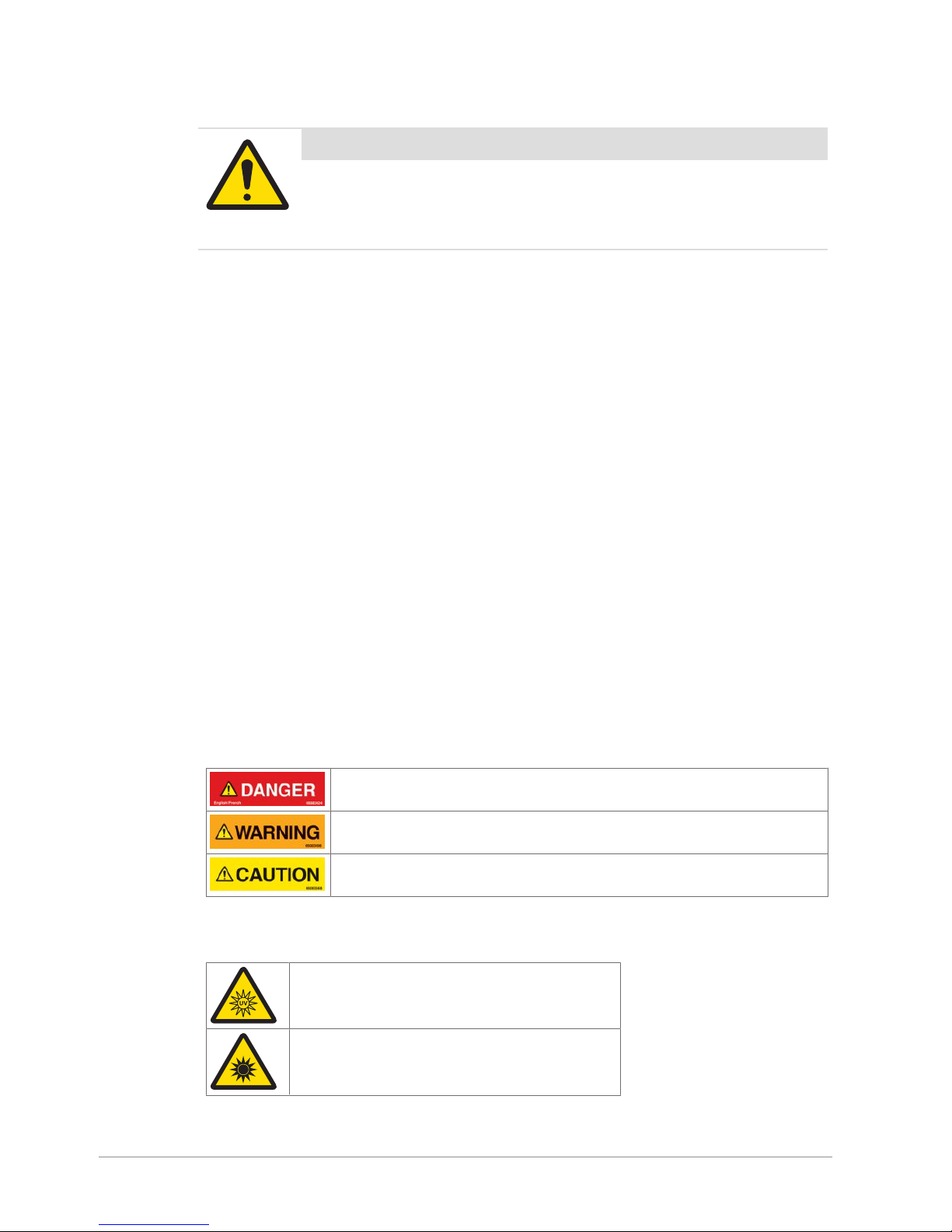
2.1.1.1 Definitions of Signal Words
Signal words describe the level of risk of a particular hazard. The color of the safety label background
indicates the risk, as shown in the following table. The definitions of the signal words are based upon the
ISO3864 definitions..
DANGER (red): This signal word indicates an imminently hazardous situation
which, if not avoided, will result in death or serious injury.
WARNING (orange): This signal word indicates a potentially hazardous situation
which, if not avoided, could result in death or serious injury.
CAUTION (yellow): This signal word indicates a potentially hazardous situation
which, if not avoided, could result in minor or moderate injury.
2.1.1.2 Meaning of Hazard Alert Symbols
The following hazard alert symbols may be installed on your equipment.
UV light
Optical radiation
4 / 34 Smart Camera - SMC Series 3 - Hardware - User Manual - Document Version B
Page 5
2.1.2 Notice
The word NOTICE does not give safety information. It is still an important word to inform you of activities
that may harm the equipment or other property. The following definition is based upon the ANSIZ535
definition.
NOTICE (blue): This word indicates important information that is not related to
personal injury which, if ignored, could result in damage to the equipment, damage
to property, malfunctions, erroneous results, or loss of data.
2.2 General Protective Procedures
Important Safety Note
Make sure that all personnel who work on or near the equipment are capable
of performing all operations in a safe manner.
• Keep the manual in a convenient location near the equipment. Replace the manual if it becomes lost or
damaged.
• Wear Personal Protective Equipment (PPE) in accordance with your plant's safety procedures.
• Understand the hazards of the equipment and the risks related to those hazards before working on or
near the equipment.
• Obey all safety procedures of the local plant.
• Do not wear loose clothing, jewelry, long hair, or anything that can become entangled with the
equipment.
• Be careful around the equipment to avoid hitting your head, arms, or other body parts against the
equipment. Be careful if the equipment is over your head.
• Be careful not to trip over cables or other parts of the equipment.
• Do not move quickly in the area around the equipment.
• Do not climb, hang onto, or use any of the part of the equipment as a support.
• Obey the lockout tagout (LOTO) procedures of the plant.
• If there is a safety-related malfunction when you are operating the equipment, press the emergency stop
device. Tell the responsible supervisor, and follow the applicable steps approved by your company to fix
the malfunction.
2.3 Safety Notes for Various Activities
Important Safety Note
Read and understand all parts of the manual before using or working on any
equipment.
The following sections list safety notes for particular activities or groups of activities. Refer to the correct
sections in the manual for more detailed instructions.
2.3.1 Transporting and Moving the Equipment
• Only transport or move the equipment if you have the applicable training as defined by your company.
• Your company has sole responsibility for the safe moving and transporting of the equipment.
• Use safe moving procedures during transporting to maintain stability and to prevent the equipment from
tipping or falling.
• Disconnect the electrical supply, the pneumatic supply, and the communication cables before you move
the equipment.
• Use the correct lifting devices. If you use a forklift, lift the equipment at the correct lift points as shown by
the blue lift point labels.
• Blue lift point labels are placed on the equipment to show recommended locations for lifting. These lift
point locations were tested with the manufacturer's forklift trucks. A qualified rigger must make sure that
the lift points are correct for your lifting equipment.
Smart Camera - SMC Series 3 - Hardware - User Manual - Document Version B 5 / 34
Page 6

• When you lift the equipment by hand, obey the safe lifting procedures of your company.
2.3.2 Installing
Only install the equipment if you have the applicable training as defined by your company.
2.3.3 Operating the Equipment and Monitoring the Inspection Process
• Before beginning operation, make sure that the area is safe.
• Know the location and effect of each emergency stop button that controls the equipment.
• Do not operate the equipment without protective guards and doors in place.
• Make sure the safety circuit is working correctly.
• Do regular inspections of the equipment.
• If there is a fault or change in the equipment behavior, stop the equipment and inform responsible
personnel.
2.3.4 Testing and Verifying the Equipment
Only do testing and verifying of the equipment if you have applicable training as defined by your company.
2.3.5 Maintaining, Cleaning and Sanitizing the Equipment
• Remove all power from the equipment before doing any work.
• Keep the equipment in good working order.
• Follow a preventative maintenance program.
• Replace parts when needed.
• Obey the lockout tagout (LOTO) procedures of the plant.
• Test (validate) the safety circuit after parts are replaced.
• Only use METTLER TOLEDO approved spare parts and accessories.
• Do not make any unauthorized modifications to the equipment.
• Replace safety labels if damaged, missing, or unreadable.
• Do a visual check of the equipment at least once during a shift to identify any visual damage or faults.
Report any equipment changes to the responsible supervisor immediately.
• When required for a hygienic production environment, do regular sanitizing of the equipment according
to your company's procedures.
• After cleaning or sanitizing, check all cables, connectors, and pneumatic hoses for leakage, loose
connections, rub marks and damage. Tighten, repair, or replace any faulty cables and air tubing, as
necessary.
2.4 Special Hazards
The following sections describe special instructions for equipment that may have special hazards.
2.4.1 Strobe Lights
• Strobe lights can cause seizures in individuals with photosensitive epilepsy.
• Individuals with photosensitive epilepsy must not operate the equipment.
• Do not operate the equipment when excessively fatigued or after consuming alcohol.
• Do not look directly at the lights, especially at close distances.
• Avoid placing the equipment in areas with reduced lighting.
• If lights are inside of an enclosure, do not open the enclosure doors when lights are flashing.
2.4.2 Lights and Laser Sensors
• Do not stare directly at any lights or lasers.
• Avoid prolonged exposure to ultraviolet (UV) light, infrared (IR) light, and lasers.
6 / 34 Smart Camera - SMC Series 3 - Hardware - User Manual - Document Version B
Page 7
3 Equipment Overview
3.1 Equipment Components
The smart camera consists of an intelligent camera with integrated signal processor and software which is
able to control different characteristics. Further, the camera hardware contains a memory, network interface,
an optical component and illumination. The illumination is integrated into the camera and external illuminations can be mounted additionally around the camera.
3.1.1 Housing
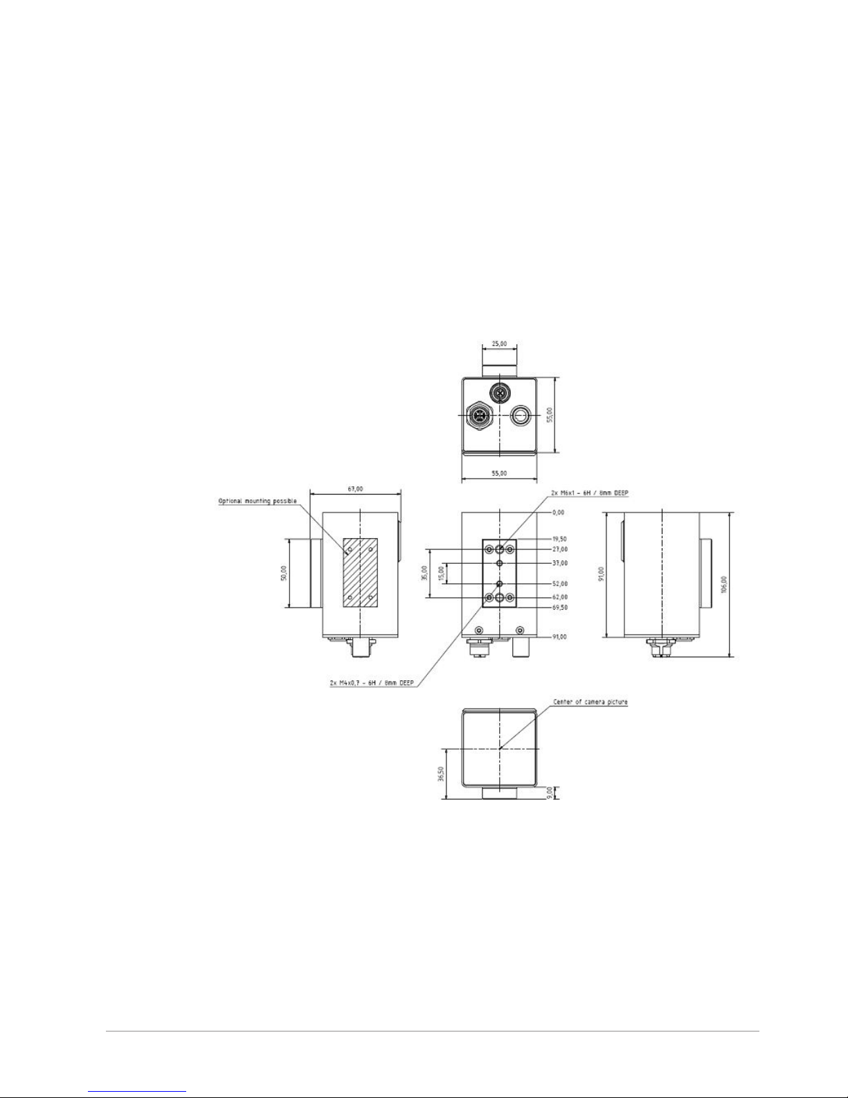
3.1.1.1 Dimensions of Housing Size 21
The image shows the dimension of housing “Size 21”. The image also shows the dimensions of the plastic
mounting block and the positions of the mounting threads 2x M4 with a distance of 15mm and the 2x M6
with a distance of 35mm. The plastic mounting block can also be placed optionally at one side of the
camera, as shown in the image. All dimensions are given in mm.
3.1.1.2 Dimensions with Cables and Connectors
The image shows the dimensions of the connectors and the recommended bending radius of cables. The
mounting direction of 90° connectors is only possible in one direction in relationship to housing, as shown
in the image.
All dimensions are given in mm.
Smart Camera - SMC Series 3 - Hardware - User Manual - Document Version B 7 / 34
Page 8
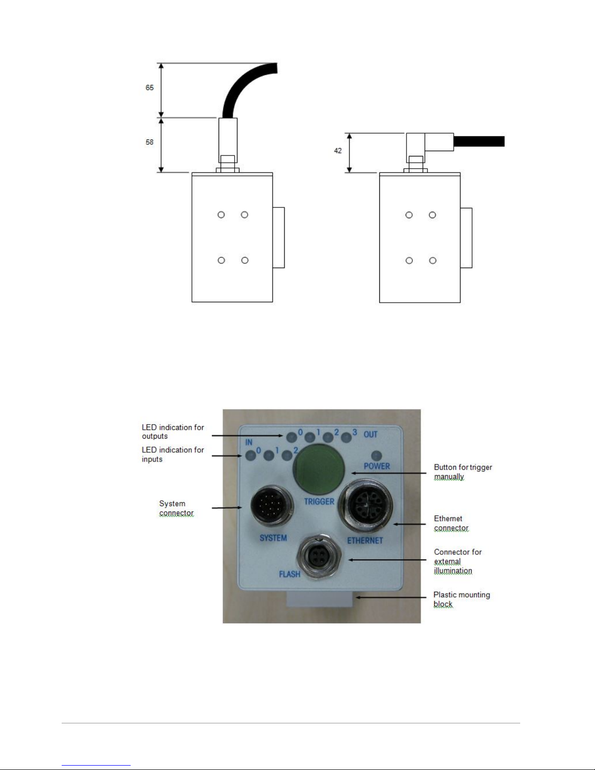
3.1.2 The Backend of the Camera
The following image shows the back side of the camera. The exact allocations are specified in the tables on
the following pages.
With the Push button in the camera’s rear panel, a camera trigger can be released. Thus, the camera starts
recording and evaluating a picture.
The LEDs in the rear panel indicate the input and output signals. The LEDs are arranged in lines. An LED
flashes, if the appropriate signal applies.
8 / 34 Smart Camera - SMC Series 3 - Hardware - User Manual - Document Version B
Page 9
Description of the I/O LEDs:
Description Function
IN0 Camera trigger from PLC
IN1 Universal, function belongs to software settings
IN2 Reset signal from PLC
OUT0 Good signal
OUT1 Camera ready signal
OUT2 Second optional good signal
OUT3 Data valid signal
3.2 Accessories for the Camera
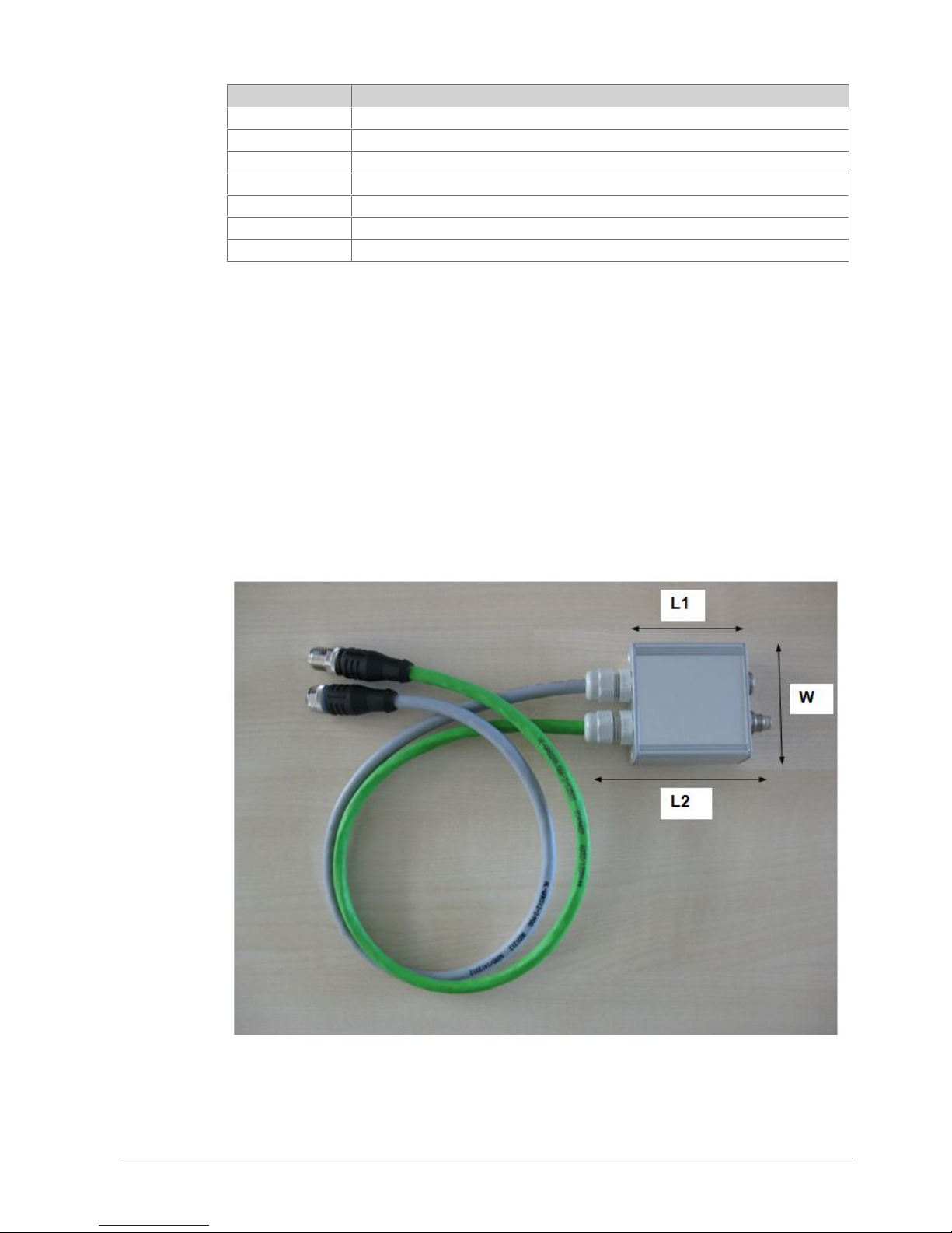
3.2.1 SMC 3 Adapter
The SMC 3 Adapter has been developed for the Smart Camera 3 series because wire assignment differs
between Smart Camera 1 series and Smart Camera 2 series. The adapter offers the possibility to connect an
SMC 3 camera to an existing system. The main use case of the SMC 3 adapter is to replace an SMC 1/
SMC 2 camera with an SMC 3 camera without replacing the SMC 1 / SMC 2 cables. Alternatively, you can
replace the cables and the Patch Panel 2 of SMC 1 / SMC 2 series with cables for Smart Camera 3 and
Patch Panel 3, without using the adapter.
On one side, the adapter has cables with plugs to connect the SMC 3 camera. The length of the cables is
about 0,5m. On the other side the adapter has sockets for plug-in cables for the SMC 1 / SMC 2 camera.
The adapter routes and crosses the wire assignment between SMC 1 / SMC 2 cables and SMC 3 cables to
get the correct wire assignment on both sides.
Dimensions of the SMC 3 Adapter with cables for the SMC 3 series
Dimension
Length, Width and Height: L1=54mm, W=55mm, H=24mm
Smart Camera - SMC Series 3 - Hardware - User Manual - Document Version B 9 / 34
Page 10
Length Including Pull Relief of Cables and Sockets
Length: L2=90mm
SMC 3 Adapter with mounted SMC 1 / SMC 2 cables.
Length Including Pull Relief of Cables and Connectors
Length: L3=120mm
The housing protection is IP54.
All other specifications of the adapter correspond to the camera specifications.
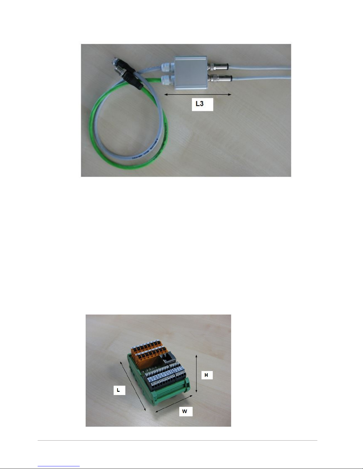
3.2.2 Patch Panel
3.2.2.1 Patch Panel Description
The Patch Panel 3.0 has been developed for the Smart Camera 3 Series. The Patch Panel is an easy
connection board for connecting cameras and scanners to a switching cabinet. Patch Panel 3.0 must be
used for Smart Camera 3 Series but is also compatible with Smart Camera 1 Series, Smart Camera 2 Series
and the comparison module VGL V7 and VGL V8 which will be used in combination with scanners.
Therefore Patch Panel 3.0 can be used in exchange for Patch Panel 1 and Patch Panel 2.
3.2.2.1.1 View and Dimensions
View and dimensions of Patch Panel 3.0 with printed circuit board L1173-0.
10 / 34 Smart Camera - SMC Series 3 - Hardware - User Manual - Document Version B
Page 11

Side view on camera clamps.
Dimension
Length, Width and Height: L=90mm, W=52mm, H=54mm
Smart Camera - SMC Series 3 - Hardware - User Manual - Document Version B 11 / 34
Page 12

LED Display
The patch panel offers some LEDs to easy identify if a signal is present. If the signal has a high status,
normally 24V, the corresponding LED gives light.
The following signals are displayed:
3.2.2.1.2 Connectivity
Each camera is connected to a patch panel inside the switching cabinet.
During installation of the camera system the length of the camera cables can be adapted to the machine.
Standard wiring of a Smart Camera System.
3.2.2.2 Overview of Camera Types and Camera Series
The smart cameras series are also named SMC 1 (or only SMC), SMC 2 and SMC 3.
12 / 34 Smart Camera - SMC Series 3 - Hardware - User Manual - Document Version B
Page 13

3.2.2.2.1 Camera Type No. of Camera 1 Series
Camera 1 series is used with patch panel 1 and can also be used with patch panel 3.0.
Smart Camera 1 Series - SMC 1
Smart Camera Type Resolution [Pixel] Status
200 640x480, B/W Replaced since 2013.10.29, by
type 205
202 1024x768, B/W Replaced since 2013.10.29, by
type 215
203 1024x768, B/W Replaced since 2013.10.29, by
type 215
204 1550x1200, B/W Replaced since 2013.10.29, by
type 215
220 640x480, Color Replaced since 2014.05.16, by
type 207
201 640x480, B/W Active
222 768x582, Color Active
223 1600x1200, Color Active
3.2.2.2.2 Camera Type No. of Camera 2 Series
Camera 2 series is used with patch panel 2 and can also be used with patch panel 3.0.
Smart Camera 2 Series - SMC 2
Smart Camera Type Resolution [Pixel] Status
150 752x480, B/W Active
205 752x480, B/W Active
215 1600x1200, B/W Active
216 1600x1200, B/W Active
240 2048x2048, B/W Active
207 752x480, Color Active
217 1600x1200, Color Active
247 2048x2048, Color Active
3.2.2.2.3 Camera Type No. of Camera 3 Series
Smart Camera 3 Series - SMC 3
Smart Camera Type Resolution [Pixel] Status
320 1600x1200, B/W Active
3.2.2.3 Description of I/O and Interfaces of Camera Series
3.2.2.3.1 Camera 1 Series
The table shows a description of inputs, outputs and interfaces offered by smart camera 1 series:
Description Description, Function Notes
IN0 Camera trigger E.g. signal from trigger sensor or PLC
IN1 Manually trigger Signal of the pushbutton at camera backside or
external signal e.g. push button
IN2 Reset Signal Only necessary with good signal = latch mode E.g.
signal from push button or PLC
IN3 Not connected Not used by camera
OUT0 Good Signal E.g. signal to PLC
OUT1 Camera Ready Signal E.g. signal to PLC
Smart Camera - SMC Series 3 - Hardware - User Manual - Document Version B 13 / 34
Page 14

Description Description, Function Notes
OUT2 Second Good Signal Optional, control windows can be separated into two
groups E.g. signal to PLC
OUT3 Data Valid Signal or External
illumination On/Off
Usually used for Data Valid e.g. signal to PLC
OUT4 Not connected Not used by camera
OUT5 Not connected Not used by camera
OUT6 Not connected Not used by camera
TxD+ Ethernet – TxD 100 MBit/s Transmit signal of camera
TxD-
RxD+ Ethernet – RxD 100 MBit/s Receive signal of camera
RxD-
TxD RS-232 – TxD Transmit signal of camera
RxD RS-232 – RxD Receive signal of camera
3.2.2.3.2 Camera 2 Series
The table shows a description of inputs, outputs and interfaces offered by smart camera 2 series:
Description Description, Function Notes
IN0 Camera trigger E.g. signal from trigger sensor or PLC
IN1 Universal Function belongs to software settings
IN2 Reset Signal Only necessary with good signal = latch mode E.g.
signal from push button or PLC
IN3 Not connected Not used by camera
OUT0 Good Signal E.g. signal to PLC
OUT1 Camera Ready Signal E.g. signal to PLC
OUT2 Second Good Signal Optional, control windows can be separated into two
groups E.g. signal to PLC
OUT3 Data Valid Signal E.g. signal to PLC
OUT4 Universal Function belongs to software settings
OUT5 Universal Function belongs to software settings
OUT6 External illumination On/Off Can switch an external illumination On/Off
TxD+ Ethernet – TxD 100 MBit/s Transmit signal of camera
TxD-
RxD+ Ethernet – RxD 100 MBit/s Receive signal of camera
RxD-
3.2.2.3.3 Camera 3 Series
The table shows a description of inputs, outputs and interfaces offered by smart camera 3 series:
Description Description, Function Notes
IN0 Camera trigger E.g. signal from trigger sensor or PLC
IN1 Universal Function belongs to software settings
IN2 Reset Signal Only necessary with good signal = latch mode E.g.
signal from push button or PLC
IN3 Not connected Not used by camera
OUT0 Good Signal E.g. signal to PLC
OUT1 Camera Ready Signal E.g. signal to PLC
OUT2 Second Good Signal Optional, control windows can be separated into two
groups E.g. signal to PLC
OUT3 Data Valid Signal E.g. signal to PLC
OUT4 Not connected Not used by camera
14 / 34 Smart Camera - SMC Series 3 - Hardware - User Manual - Document Version B
Page 15

Description Description, Function Notes
OUT5 Not connected Not used by camera
OUT6 Not connected Not used by camera
D1+, TxD+ Ethernet – TxD or Bi-directional 100/1000 MBit/s Transmit signal of camera
D1-, TxD-
D2+, RxD+ Ethernet – RxD or Bi-directional 100/1000 MBit/s Receive signal of camera
D2-, RxD-
D3+ Ethernet – Bi-directional 100/1000 MBit/s Bi-directional data signal of camera
D3-
D4+ Ethernet – Bi-directional 100/1000 MBit/s Bi-directional data signal of camera
D4-
TxD RS-232 – TxD Transmit signal of camera
RxD RS-232 – RxD Receive signal of camera
Smart Camera - SMC Series 3 - Hardware - User Manual - Document Version B 15 / 34
Page 16

3.2.2.4 Assigning Wires to Patch Panel Clamps
3.2.2.4.1 Overview of Patch Panel Clamps
The following image shows the assignment of clamps to the machine signals. You can use the machine
clamps to connect the inputs and outputs of the PLC or a trigger sensor or optocouplers and the power
supply.
Graphical top view on patch panel
The next chapters show the wire-to-clamp-assignments for connecting different cameras and comparator
boxes to the patch panel.
16 / 34 Smart Camera - SMC Series 3 - Hardware - User Manual - Document Version B
Page 17

3.2.2.4.2 Clamp Assignment for SMC 1, VGL V7 and VGL V8
The follwoing tables show the Patch Panel 3.0-clamp-assignment for SMC 1 (SMC) and the clamp
assignment for comparator VGL V7 and VGL V8.
Power supply Input RS232 Interface Shield
Clamp
number
17 18 19 20 21 22 23 24 25
Clamp
function
+24V Minus In0 In1 In2 In3 RS232
TxD
RS232
RxD
Shield
Assignm
ent
cable
and wire
System
cable
whiteblue
System
cable
blue
System
cable
brown
I/O cable
brown
I/O cable
yellow
I/O cable
orange
I/O cable
blue
I/O cable
violet
System
cable
Output Shield
Clamp
number
26 27 28 29 30 31 32 33 34
Clamp
function
Out0 Out1 Out2 Out3 Out4 Out5 Out6 Not used Shield
Assignm
ent
cable
and wire
System
cable
whitebrown
I/O cable
black
I/O cable
green
I/O cable
red
- - - - I/O cable
Ethernet Interface
Clamp number 35 36 37 38
Clamp function TxD+
D1+
TxDD1-
RxD+
D2+
RxDD2-
Assignment cable
and wire
System cable
white-orange
System cable
orange
System cable
white-green
System cable
green
Ethernet Interface
Clamp number 39 40 41 42
Clamp function D3- D3+ D4+ D4-
Assignment cable
and wire
- - - -
Smart Camera - SMC Series 3 - Hardware - User Manual - Document Version B 17 / 34
Page 18

3.2.2.4.3 Clamp Assignment for SMC 2
The following tables show the Patch Panel 3.0-clamp-assignment for SMC 2.
Power supply Input RS232 Interface Shield
Clamp
number
17 18 19 20 21 22 23 24 25
Clamp
function
+24V Minus In0 In1 In2 In3 RS232
TxD
RS232
RxD
Shield
Assignm
ent
cable
and wire
System
cable
whiteblue
System
cable
blue
System
cable
brown
I/On
cable
brown
I/O cable
yellow
- - - System
cable
Output Shield
Clamp
number
26 27 28 29 30 31 32 33 34
Clamp
function
Out0 Out1 Out2 Out3 Out4 Out5 Out6 Not used Shield
Assignm
ent
cable
and wire
System
cable
whitebrown
I/O cable
black
I/O cable
green
I/O cable
red
I/O cable
blue
I/O cable
violet
I/O cable
orange
- I/O cable
Ethernet Interface
Clamp number 35 36 37 38
Clamp function TxD+
D1+
TxDD1-
RxD+
D2+
RxDD2-
Assignment cable
and wire
System cable
white-orange
System cable
orange
System cable
white-green
System cable
green
Ethernet Interface
Clamp number 39 40 41 42
Clamp function D3- D3+ D4+ D4-
Assignment cable
and wire
- - - -
18 / 34 Smart Camera - SMC Series 3 - Hardware - User Manual - Document Version B
Page 19

3.2.2.4.4 Clamp Assignment for SMC 3
The following tables show the Patch Panel 3.0-clamp-assignment for SMC 3:
Power supply Input RS232 Interface Shield
Clamp
number
17 18 19 20 21 22 23 24 25
Clamp
function
+24V Minus In0 In1 In2 In3 RS232
TxD
RS232
RxD
Shield
Assignm
ent
cable
and wire
System
cable
brown
System
cable
blue
System
cable
white
System
cable
green
System
cable
pink
- System
cable
greypink
System
cable
red-blue
System
cable
Output Shield
Clamp
number
26 27 28 29 30 31 32 33 34
Clamp
function
Out0 Out1 Out2 Out3 Out4 Out5 Out6 Not used Shield
Assignm
ent
cable
and wire
System
cable
yellow
System
cable
black
System
cable
grey
System
cable
red
- - - System
cable
violet
Ethernet
cable
Ethernet Interface
Clamp number 35 36 37 38
Clamp function TxD+
D1+
TxDD1-
RxD+
D2+
RxDD2-
Assignment cable
and wire
Ethernet cable
white-orange
Ethernet cable
orange
Ethernet cable
white-green
Ethernet cable
green
Ethernet Interface
Clamp number 39 40 41 42
Clamp function D3- D3+ D4+ D4-
Assignment cable
and wire
Ethernet cable
white-blue
Ethernet cable
blue
Ethernet cable
white-brown
Ethernet cable
brown
Smart Camera - SMC Series 3 - Hardware - User Manual - Document Version B 19 / 34
Page 20

3.3 Assignment of Plugs and Cables
With the 12-pin-system-plug the camera is supplied with 24V and can be connected with input and output
signal to e.g. a PLC or to optocouplers. The camera establishes a connection to the network with the
Ethernet cable.
3.3.1 System Cable
The images below show the M12x1 female connector with “A” encoding of the system cable.
The cross section is 12x0,14mm² (AWG26). Protection rating is IP67.
View on the front side of female inserts.
The table shows the assignment and function of the system cable.
Pin No. Color Description Function Notes
1 Brown +24V Power supply
+24V
-
2 Blue GND Power supply
minus, GND
-
3 White IN0 Trigger signal Default: Trigger signal from trigger
sensor or PLC
Optional: -
4 Green IN1 Universal Default: No setting
Optional: Function belongs to software
settings
5 Pink IN2 Reset signal /
universal
Default: Reset of different camera stop
or error functions, e.g. signal from
push button or PLC.
Optional: Function belongs to software
settings
6 Yellow OUT0 Good signal Default: Good signal, e.g. signal for
PLC
Optional: -
7 Black OUT1 Ready signal Default: Ready signal, e.g. signal for
PLC
Optional: Function belongs to software
settings
20 / 34 Smart Camera - SMC Series 3 - Hardware - User Manual - Document Version B
Page 21

Pin No. Color Description Function Notes
8 Grey Out2 Second good
signal
Default: Second good signal, e.g.
signal for PLC
Optional: Function belongs to software
settings
9 Red Out3 Data valid signal Default: Data valid signal, e.g. signal
for PLC
Optional: Function belongs to software
settings
10 Violet Not connected - -
11 Grey/Pink RS-232 RS-232 - TxD RS-232 interface, transmit signal of
camera
12 Red/Blue RS-232 RS-232 - RxD RS-232 interface, receive signal of
camera
3.3.2 Ethernet Cable
The images below show the M12x1 male connector with “X” encoding of the Ethernet cable.
The cross section is 4x2x0,14mm² (AWG26). Protection rating is IP67.
View on the front side of male inserts.
The table shows the assignment and function of the Ethernet cable.
Pin No. Color Description Function Notes
1 White (Orange) D1+, TxD+ Ethernet – TxD or
Bi-directional
10/100/1000Mbit
Ethernet network,
e.g. connected to
an Ethernet switch.
2 Orange D1-, TxD-
3 White (Green) D2+, RxD+ Ethernet – RxD or
Bi-directional
4 Green D2-, RxD-
5 White (Brown) D4+ Ethernet – Bi-direc-
tional
6 Brown D4-
7 White (Blue) D3+ Ethernet – Bi-direc-
tional
8 Blue D3-
3.3.3 Illumination Cable
The images below show the M9x0,5 male connector of the illumination cable.
The cross section is 3x0,25mm² (AWG24). Protection rating is IP67.
Smart Camera - SMC Series 3 - Hardware - User Manual - Document Version B 21 / 34
Page 22

Back side of male inserts
The table shows the assignment and function of the illumination cable.
Pin No. Color Description Function Notes
1 Not connected - - -
2 Green +24V Power supply
+24V
-
3 Brown Trigger Trigger signal Default: Trigger
signal from camera
to illumination
Optional: -
4 White GND Power supply
Minus, GND
-
22 / 34 Smart Camera - SMC Series 3 - Hardware - User Manual - Document Version B
Page 23

4 Installation and Integration
4.1 Installing the Camera
To install your SMC 3 camera:
1 You can mount the camera in horizontal, vertical or any other position.
NOTICE
If the camera housing is mounted in rotated positions, also the image of camera is
rotated. Use the software settings to rotate the image back to horizontal.
2 Use the plastic block at the bottom of the camera to mount the camera with 2 x M4 or 2 x M6 screws.
3 Mount the camera in the correct distance to the object, e.g. 135 mm as default value.
NOTICE
The distances can differ depending on camera types or applications.
4 Check that the positive edge of the trigger signal is sent to the camera in the moment in which the print
of your product is in the middle of the camera's view field.
4.2 Mounting the Patch Panel in a Control Cabinet
The images show the stripping of the two camera cables, system cable and ethernet cable. The stripped
length of the cables should be short as possible.
The image shows the preparation of the system cable with the stripping length.
The image shows the preparation of the ethernet cable with the stripping length.
It is recommended to leave the aluminium foil about 35mm around the ethernet pairs and strip only about
35mm. The insulation of about 15mm prevents a division of the shielding. The length of about 15mm is a
good choice if the distance between screen bus bar (grounding bus bar) and patch panel is about 25mm.
If the distance exceeds 25mm, also the length of insulation should be longer than 15mm.
The image shows the patch panel on a mounting rail and a screen bus bar. Mount the shielding of cables
to a screen bus bar. Connect the screen bus bar to protected earth PE.
Smart Camera - SMC Series 3 - Hardware - User Manual - Document Version B 23 / 34
Page 24

The image shows an example for installation of Patch Panel 3.0 with camera cables (grey and green),
ethernet patch cable (white) and wiring of switching cabinet (blue) with power, inputs and outputs and
protecting earth wire (green/yellow).
4.3 Standard Network Address
The standard network address configuration is as follows:
Device Standard IP-Address
Panel PC with touch (e.g. VCU)
VCU 15,6” 2.0
192.168.100.200
24 / 34 Smart Camera - SMC Series 3 - Hardware - User Manual - Document Version B
Page 25

Device Standard IP-Address
Smart Camera 192.168.100.215
Comparator box VGL V7 with scanner LAS1000 192.168.100.221
The standard subnet mask is 255.255.255.0 for all devices.
4.4 Example of Wiring a System
The following example consists of a control cabinet, a VCU (=a monitor with integrated PC), an Ethernet
switch, a smart camera, a patch panel and a PLC. The graphic shows the components and the wiring:
Wiring diagram example
Smart Camera - SMC Series 3 - Hardware - User Manual - Document Version B 25 / 34
Page 26

5 Operation
The camera is handled with a cable-bound network LAN (Local Area Network). A PC must be present in this
network for the operation of the camera. The PCE Line Manager and Inspection Manager are suitable
software, in order to operate the camera comfortably: Descriptive visualizations indicate the adjusting
options on the touch display and ensure comfortable operation by means of large-sized touch buttons.
The PC software (PLM, IM or SMC Client) offers all the necessary functions to handle the camera. The
screen shows e.g. buttons and a keyboard to send commands and characters. For mounting the camera
and for setting up the system, a live image can be displayed on the screen.
5.1 Optical Parameters
5.1.1 Orientation of Field of View to Camera Housing
The image shows the orientation of the field of view in relation to the camera housing.
5.1.2 Center of Image to Camera Housing
The image below shows the center of the camera image in relation to the camera housing.
All dimensions are given in mm.
26 / 34 Smart Camera - SMC Series 3 - Hardware - User Manual - Document Version B
Page 27

5.1.3 Adjusting Focus and Aperture at the Lens
The image below shows the removed cap of the camera housing for lens adjustment. With the focus ring of
the ens, you can adjust the image for best sharpness of the image. Adjusting the focus is necessary if the
distance between the camera and the object changes. With the aperture ring you can adjust the brightness
of the image.
Adjusting focus and lens of the camera
By default, the reading distance of the camera is 135 mm; as a general rule, the reading distances are set
during the installation of the system. Adjust the image sharpness yourself, if you need different reading
distances for smaller letters or larger labels.
With the software parameter shutter value, you can set the main brightness of the image. Adjusting
the aperture is necessary to fine-tune the brightness of the camera image. For example, the adjustment is
necessary for barcode- and DM-Code grading to get valid results. Therefore, use a calibration card as
reference object in front of the camera.
To adjust the focus and aperture use available software functions. To see and evaluate the best sharpness
in the software, set the image transfer quality parameter to 1 and use the software zoom
functions to increase the image:
1 Increase the size of the displayed details either by turning on the Zoom mode in the Main menu and / or
by switching the image quality to 1 in Config. image transfer in the System parameter menu.
Smart Camera - SMC Series 3 - Hardware - User Manual - Document Version B 27 / 34
Page 28

2 Switch the camera to the Live image mode.
3 Adjust the distance between the object and the camera until the image displayed on the PLM screen is
the size that you want.
4 Turn the ring for the focal distance using a suitable tool such as a small pointed screwdriver until you
see a clear, sharp image on the screen.
5 Change the software parameter quality of image transfer back to the pre-set value of 2
and/ or turn off the Zoom mode.
NOTICE
Some cameras have an electronically adjustable lens. If the software detects the presence
of an electronically adjustable lens, it will display the buttons Focus and Autofocus in the
menu Optical Settings menu. If your camera provides an electronically adjustable lens,
make all the adjustments via the software using the Focus or Autofocus buttons and
sliders.
28 / 34 Smart Camera - SMC Series 3 - Hardware - User Manual - Document Version B
Page 29

6 Maintenance
The device has been specially designed for industrial requirements. As a result, reliable operation is
guaranteed under the normal conditions existing in production plants, provided that trained personnel have
installed the device.
For perfect operation, it is necessary to clean the glass plate of the camera housing at regular intervals. For
cleaning, only use the cleaning cloths and agents intended specially for this purpose.
NOTE
The device itself has no mechanical wearing parts and therefore requires no
maintenance.
Smart Camera - SMC Series 3 - Hardware - User Manual - Document Version B 29 / 34
Page 30

7 Disposal
In conformance with the European Directive 2012/19/EU on Waste Electrical and
Electronic Equipment (WEEE) this device may not be disposed of in domestic waste. This
also applies to countries outside the EU, per their specific requirements.
Please dispose of this product in accordance with local regulations at the collecting point
specified for electrical and electronic equipment. If you have any questions, please
contact the responsible authority or the distributor from which you purchased this device.
Should this device be passed on to other parties (for private or professional use), the
content of this regulation must also be related.
Thank you for your contribution to environmental protection.
30 / 34 Smart Camera - SMC Series 3 - Hardware - User Manual - Document Version B
Page 31

8 Technical Data
8.1 Technical Data Smart Camera 3.0
The following specifications apply to the Smart Camera 3 series.
Housing Aluminum,
Dimensions as example for camera type no. 320 and housing size 21:
LxWxH: 91 mm x 55 mm x 55 mm
Protection of housing IP65: dust-tight and protection against water jets. No ingress of dust. Water-
protected by a nozzle against enclosure from any direction.
Power supply 24V DC, min. 20V, max. 28V,
Current during start up: max. about 1A,
Current during operation: about 150mA
Image processing Internally, with special machine vision processor.
Inputs 3 inputs 24 V DC, max. 28V permanent, response threshold: High: about
>13V, Low: about <7V
Outputs 4 Outputs 24V DC, type PNP, max. 100mA permanent, max. 400mA peak
short-circuit-proof, protected against overload and protected against external
voltage
Interface Ethernet 100/1000 Mbit/s, LAN
Interface RS-232
Illumination White LEDs in flash operation
Standard lens (1) C-Mount, 12 mm focal length
Standard distance
between object and
camera housing (1)
135 mm
Standard visible area (1) LxW: 95 mm x 71 mm
Camera inclination angle 0-10 degrees in relation to vertical and product horizontal
Environmental
conditions at transport
and storage
-20°C (-4°F) to +80°C (+176°F),
Max. humidity 90%, non-condensing
Environmental
conditions at operation
0°C (+32°F) to +50°C (+122°F),
Max. humidity 80%, non-condensing
Weight 430g
(1) Other configurations are available.
8.2 Technical Data Patch Panel
The following specifications apply to the Patch Panel.
Dimensions
Length, Width and Height: L=90mm, W=52mm, H=54mm
Power supply +24V DC, approx. 10mA
Smart Camera - SMC Series 3 - Hardware - User Manual - Document Version B 31 / 34
Page 32

Orange clamps
Wiring inside the
switching cabinet
Screwdriver blade e.g. 0,6 x 3,5mm
Clamping range min. 0,12mm², AWG 26
Clamping range max. 2,5mm², AWG 12
Single solid wire min. 0,2mm², AWG 24
Single solid wire max. 2,5mm², AWG 12
Single flexible wire min. 0,2mm², AWG 24
Single flexible wire max. 2,5mm², AWG 12
Wire with plastic collar ferrule min. 0,14mm², AWG 25
Wire with plastic collar ferrule max. 2,0mm², AWG 14
Strip of insulation 10mm
Sleeve length of ferrule >= 8mm to 10mm
Black clamps
Wires of camera / VGL
Screwdriver blade e.g. 0,6 x 3,5mm
Clamping range min. 0,13mm², AWG 25
Clamping range max. 1,5mm², AWG 16
Single solid wire min. 0,2mm², AWG 24
Single solid wire max. 1,5mm², AWG 16
Single flexible wire min. 0,2mm², AWG 24
Single flexible wire max.1,5mm², AWG 16
Wire with plastic collar ferrule min. 0,14mm², AWG 25
Wire with plastic collar ferrule max. 0,75mm², AWG 18
Strip of insulation 8mm
Sleeve length of ferrule 8mm
Environmental
conditions at transport
and storage
-20°C (-4°F) to +80°C (176°F),
max. humidity 90%, non condensing
Environmental
conditions at operation
0°C (32°F) to +50°C (122°F),
max. humidity 80%, non condensing
Weight 90g
32 / 34 Smart Camera - SMC Series 3 - Hardware - User Manual - Document Version B
Page 33

Intentionally left blank
Smart Camera - SMC Series 3 - Hardware - User Manual - Document Version B 33 / 34
Page 34

Pharmacontrol Electronic GmbH
Gernsheimer Strasse 2
64673 Zwingenberg, Germany
Tel. +49 6251 8545-0
Fax +49 6251 8545-111
www.mt.com
Subject to technical changes.
© Pharmacontrol Electronic GmbH 04/2017
Smart Camera - SMC Series 3 - Hardware - User Manual - Document Version B
For more information
www.mt.com/pce
 Loading...