

Page 1
®
Sonicator
Instruction Manual
Plus 930
1333 South Claudina Street • Anaheim, CA 92805, U. S. A.
Toll Free: (800) 854–9305 • Telephone: (714) 533–2221 • FAX: (714) 635–7539
Web Site: http://www.mettlerelectronics.com • Email: [email protected]
IR9–07 Rev.J_09/13/17
Page 2

Mettler Electronics Corp.— Rev.J_09/13/17
Copyright © 2002-2017 by Mettler Electronics Corp.—Anaheim, CA
FCC Frequency Interference Statement
Warning:
This equipment generates and uses radio frequency energy and, if not installed and
operated in strict accordance with the manufacturer’s instructions, may cause radio
frequency interference.
Notice 1:
This equipment has been verified to comply with the specifications in Part 18 of FCC
Rules, which are designed to provide reasonable protection against radio frequency
interference. However, there is no guarantee that interference will not occur in a particular
installation.
Notice 2:
If this equipment is found to be the source of radio frequency interference, which can be
determined by turning the equipment off and on, the user should try to correct the
interference by one or more of the following measures:
• Reorient the receiving antenna (as applicable).
• Relocate the Sonicator Plus 930 with respect to the receiver.
• Move the Sonicator Plus 930 away from the receiver.
• Plug the Sonicator Plus 930 into a different outlet than the receiver.
• If necessary, the user should consult with the dealer or manufacturer for additional
suggestions. (The user may find FCC’s “Interference Handbook” helpful. It is available
from the U.S. Government Printing Office, Washington, D.C. 20402, Stock No. 004–000–
00450–7.)
Notice 3:
The manufacturer is not responsible for any interference caused by unauthorized
modification to this equipment.
Mettler Electronics Corp.
1333 S. Claudina St.
Anaheim, CA 92805
Toll Free: (800) 854–9305
Or (714) 533–2221
2
Page 3

Sonicator Plus 930 Instruction Manual— Rev.J_09/13/17
Table of Contents
Section Title Page
1 Introduction 5
1.1 Introduction to the Sonicator Plus 930 5
1.2 Introduction to this Manual 6
1.3 Safety Precautions 6
1.4 Caution 7
1.5 Shipping Damage 7
1.6 Package Contents 7
1.7 Limited Warranty 8
2 Symbol Glossary and List of Abbreviations 9
2.1 Symbol Glossary 9
2.2 List of Abbreviations 12
3 Installation Instructions 13
3.1 Installation 13
3.2 EMC Guidance 15
4 Operating Instructions 19
4.1 A Note About Electrodes 20
4.2 General Operating Instructions 21
4.3 General Set-up Procedure 21
4.4 Stimulation Set-up Procedure 23
4.5 Ultrasound Set-up Procedure 25
4.6 Combination Therapy Set-up Procedure 27
4.7 Electrode Positioning 30
5 Indications, Contraindications, Precautions and Adverse Reactions 33
5.1 Indications for Therapeutic Ultrasound 33
5.2 Indications for Neuromuscular Electrical Stimulation 33
5.3 Contraindications for Therapeutic Ultrasound 34
5.4 Contraindications for Neuromuscular Electrical Stimulation 34
5.5 Warnings for Neuromuscular Electrical Stimulation 35
5.6 Precautions for Therapeutic Ultrasound 35
5.7 Precautions for Neuromuscular Electrical Stimulation 36
5.8 Side Effects/Adverse Reactions for Neuromuscular Electrical Stimulation 37
6 Maintenance and Troubleshooting 39
6.1 Cleaning the Sonicator Plus 930 39
6.2 Routine Maintenance 39
6.3 Troubleshooting the Sonicator Plus 930 39
7 Ultrasound Theory of Operation 43
7.1 Introduction to Ultrasound 43
7.2 Output Levels 46
7.3 Continuous and Pulsed Waves 47
8 References 49
9 Specifications 51
9.1 General Specifications 51
9.2 Ultrasonic Generator Specifications 51
9.3 Ultrasonic Applicator Specifications 52
9.4 Waveform Specifications 54
9.5 Amplitude Modulation Specifications 56
3
Page 4

Mettler Electronics Corp.— Rev.J_09/13/17
10 Accessories 57
10.1 Ordering Information 57
10.2 Sonicator Plus 930 Accessories 57
List of Figures
No. Title Page
1.1 Sonicator Plus 930 5
3.1 Sonicator Plus 930, Back view—Mains Power Switch and Line Cord connection 14
3.2 Sonicator Plus 930, Front View—Electrode Cable and Ultrasound Applicator
Connections
3.3 Connecting the Applicator to the Universal Applicator Cable 14
4.1 Front membrane panel and LED indicators 19
4.2 Electrode Sizes and Current Density 20
4.3 Quadpolar Electrode Placement Technique 30
4.4 Bipolar Electrode Placement Technique 31
4.5 Monopolar Electrode Placement Technique 31
4.6 Using the Pencil Electrode 32
7.1 Ultrasound Absorption, Skin 43
7.2 Ultrasound Absorption, Fat 44
7.3 Ultrasound Absorption, Muscle with the Ultrasound Beam Perpendicular to the
Muscle Fibers
7.4 Ultrasound Absorption, Bone 44
7.5 High Frequency Sound Waves 45
7.6 Ultrasound Application Techniques 46
7.7 Underwater Treatment Technique 46
7.8 Differences Between Transducers 46
9.1 Pulse Waveform—20% Duty Cycle 52
9.2 Continuous Waveform—100% Duty Cycle 52
9.3 5 cm² Applicator (1 MHz), ME7513—Three Dimensional Beam Patterns 53
9.4 5 cm² Applicator (3.2 MHz), ME7513—Three Dimensional Beam Patterns 53
9.5 10 cm² Applicator (1 MHz), ME7310—Three Dimensional Beam Patterns 53
9.6 1 cm² Applicator (3.3 MHz), ME7331—Three Dimensional Beam Patterns 53
9.7 Interferential Waveform 54
9.8 Premodulated Waveform 55
9.9 Medium Frequency (Russian) Waveform 56
14
44
4
Page 5
Sonicator Plus 930 Instruction Manual— Rev.J_09/13/17
Section 1: Introduction
1.1 Introduction to the Sonicator Plus 930
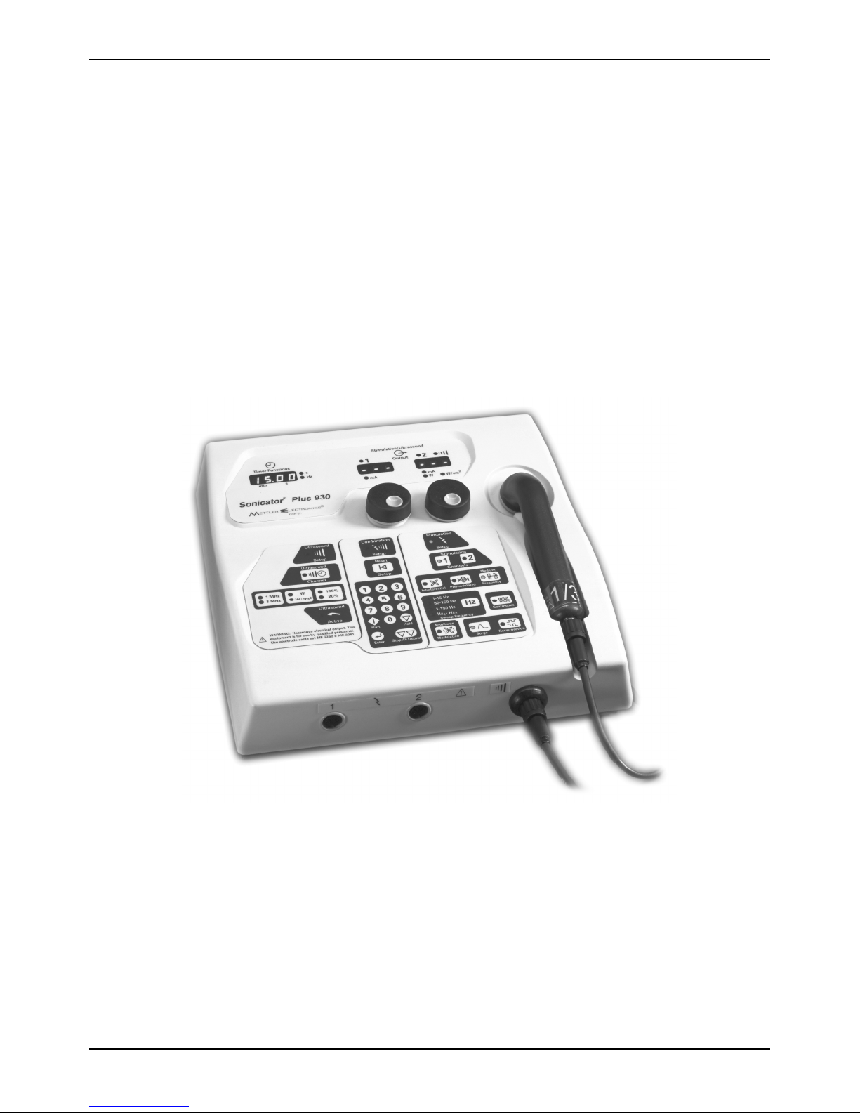
Thank you for purchasing the Sonicator Plus 930 two-channel combination unit for
therapeutic ultrasound and muscle stimulation. The microprocessor controlled Sonicator
Plus 930 provides interferential, premodulated and medium frequency waveforms with
enhanced reliability and ease of use. In addition the Sonicator Plus 930 offers 1 and 3 MHz
ultrasound using a dual frequency 5 cm² applicator. An additional two applicators are also
available: 1 Mhz, 10 cm² and 3 Mhz, 1 cm². The Sonicator Plus 930 must be specially calibrated
to use these applicators so that they function properly.
The two–channel Sonicator Plus 930 allows you to utilize up to two different waveforms
using two channels simultaneously. You can choose between several different amplitude
modulation options such as the surge, reciprocation and vector rotation. The interferential
and premodulated modes offer frequency modulation as well as a static frequency option.
The membrane panel provides both tactile and audio feedback when buttons are pressed.
Blinking LED’s guide you through the easy setup routine. The Sonicator Plus 930 features
new “Reset” and separate “Enter” keys to make programming your treatment setups
easier.
Large, soft-touch control knobs make adjusting power for ultrasound and stimulation easy
to accomplish with no guesswork involved. Two LED output displays allow you to
monitor two channels simultaneously for two channel or combination treatment protocols.
These also allow you to adjust both channels of an interferential protocol simultaneously
while monitoring the current.
Figure 1.1— Sonicator Plus 930
5
Page 6

Mettler Electronics Corp.— Rev.J_09/13/17
The Sonicator Plus 930 can provide electrical stimulation only, ultrasound only and
combination therapy with the premodulated and medium frequency waveforms. Add the
optional treatment cart to create a mobile treatment center for your office.
The Sonicator Plus 930 was certified by Intertek Testing Services to meet the requirements
for ETL Listing per the following standards:
UL 60601-1 Standard for Safety Medical Electrical Equipment, Part 1:
General Requirements for Safety Second Edition.
CAN/CSA C22.2 NO 601.1-M90 – Medical Electrical Equipment – Part 1:
General Requirements for Safety General Instruction No 1; Supplement 1;
1994 R(1997)
IEC60601-2-5 – Safety of Ultrasonic Therapy Equipment
IEC60601-2-10 – Safety of Nerve and Muscle Stimulators
In addition, the Sonicator Plus 930 meets the following standards for radio frequency
emissions:
FCC Part 18
IEC/EN 60601-1-2
Mettler Electronics Corp. has been certified by VTT Expert Services LTD to be compliant
with EN ISO 13485:2003 and MDD 93/42/EEC Annex II requirements. In addition, Mettler
is certified by DQS Medizinprodukte GMBH to be compliant with ISO 13485:2003
(CMDCAS) Canadian Medical Device requirements.
1.2 Introduction to This Manual
Read the contents of this manual before treating patients with the Sonicator Plus 930.
This manual has been written to assist you with the safe operation of the Sonicator Plus
930. It is intended for use by the owners and operators of the Sonicator Plus 930. The goal
of this manual is to direct the correct operation and maintenance of this unit.
The specifications and instructions presented in this manual are in effect at the time of its
publication. These instructions may be updated at any time at the discretion of the
manufacturer.
1.3 Safety Precautions
The Sonicator Plus 930 operates with high voltages. Qualified biomedical technicians with
training in ultrasound and neuromuscular stimulator service should perform servicing of
the Sonicator Plus 930 or it should be returned directly to the factory. To maximize safety
during use, the unit should be plugged into a grounded wall outlet. General safety
guidelines for medical electronic equipment should be followed.
To assure compliance with FDA, 21 CFR 1050.10 standards, the ultrasound portion of the
Sonicator Plus 930 should be calibrated and safety tested on an annual basis. This service
may be obtained from the manufacturer by sending the Sonicator Plus 930 in its original
shipping container to Mettler Electronics Corp., 1333 South Claudina Street, Anaheim, CA
92805, ATTN: Service Department. (Telephone toll free: (800) 854–9305, Alternate telephone
number: 1 (714) 533–2221) This service may also be performed by qualified biomedical
engineers or technicians trained in ultrasound calibration.
6
Page 7

Sonicator Plus 930 Instruction Manual— Rev.J_09/13/17
NOTE: All warranty repairs must be performed by Mettler Electronics Corp. or by a
service facility authorized by Mettler Electronics to perform warranty repair work.
A service manual for the Sonicator Plus 930 is available from Mettler Electronics Corp. for a
nominal charge.
1.4 Caution
Federal law restricts the sale of this device to, or on the order of a physician, dentist,
veterinarian or any other practitioner licensed by law of the state in which he practices.
Use of controls or adjustments or performance of procedures other than those specified
herein may result in hazardous exposure to ultrasonic energy. The electric energy
delivered by this device may possibly be lethal. Treatment should be administered only
under the direct supervision of a health care professional.
1.5 Shipping Damage
Your new Sonicator Plus 930 is shipped complete in one carton. Upon receipt, please
inspect the carton and the unit for visible and hidden damage. If you discover any
damage, hold all shipping materials, including the carton, and call the shipping agent who
delivered the unit. They are responsible for all damage in transit; therefore, all claims
should be filed directly with them. The factory will not be responsible for any damage in
shipment, nor allow any adjustments unless proper formal claim has been filed by the
receiver against the carrier.
The carton in which your new Sonicator Plus 930 was received is specially designed to
protect the unit during shipping. Please retain all shipping materials in the event that you
will need to return your unit for servicing. NOTE: All warranty repairs are to be
performed by Mettler Electronics Corp. or an authorized Mettler Electronics warranty
repair center.
1.6 Package Contents
Your new Sonicator Plus 930 comes complete with all the necessary components to
perform therapeutic ultrasound, neuromuscular electrical stimulation and combination
therapy. Below is a list of items that are included in the shipping carton.
1. Sonicator Plus 930
2. Ultrasound applicator, 5 cm² at 1 and 3 MHz, (ME 7513)
3. Hooded, water-proof universal applicator cable, (ME 7392)
4. Sonigel, ultrasound couplant gel, one sample sized tube
5. Two electrode cable sets, (ME 2260)
6. One single wire electrode cable for combination therapy (ME 2261)
7. One package each V Trodes, 2" diameter (ME 2702) and 3" diameter (ME 2703)
8. Detachable U.L. listed, hospital–grade line cord, (ME 7293)
9. Instruction Manual
7
Page 8

Mettler Electronics Corp.— Rev.J_09/13/17
1.7 Limited Warranty
The Sonicator Plus 930 combination unit for neuromuscular electrical stimulation and
therapeutic ultrasound is warranted against defects in materials and workmanship for a
period of two years from date of purchase. . The Sonicator Plus 930 applicator is warranted
against defects in materials and workmanship for a period of one year from date of
purchase. During the applicable warranty period Mettler Electronics Corp. will, at its
discretion, either repair or replace the Product without charge for these types of defects.
For service under this warranty, the Product must be returned by the buyer within the
applicable warranty period to Mettler Electronics Corp. Shipping charges to Mettler
Electronics Corp. under this warranty must be paid by the buyer. The buyer must also
include a copy of the sales receipt or other proof of the date of purchase. If the Product
is returned without proof of the date of purchase, it will be serviced as an out–of–
warranty product at Mettler Electronics Corp.'s prevailing service rates.
Alteration, misuse, or neglect of the Product voids this warranty. Except as specifically
set forth above, Mettler Electronics Corp. makes no warranties, express or implied,
including without limitation any implied warranty of merchantability or fitness for a
particular purpose, with respect to the Product. If any implied warranties apply as a
matter of law, they are limited in duration to one year.
Mettler Electronics Corp. shall not be liable for any indirect, special, consequential or
incidental damages resulting from any defect in or use of the Product.
Any legal action brought by the buyer relating to this warranty must be commenced
within one year from the date any claim arises and must be brought only in the state or
federal courts located in Orange County, California.
Some states do not allow limitations on how long an implied warranty lasts, or the
exclusion or limitation of incidental or consequential damages, so the above limitations or
exclusions may not apply to the buyer. This warranty gives the buyer specific legal rights,
and the buyer may also have other rights which vary from state to state.
8
Page 9
Section 2—Symbol Glossary
smin
0
and List of Abbreviations
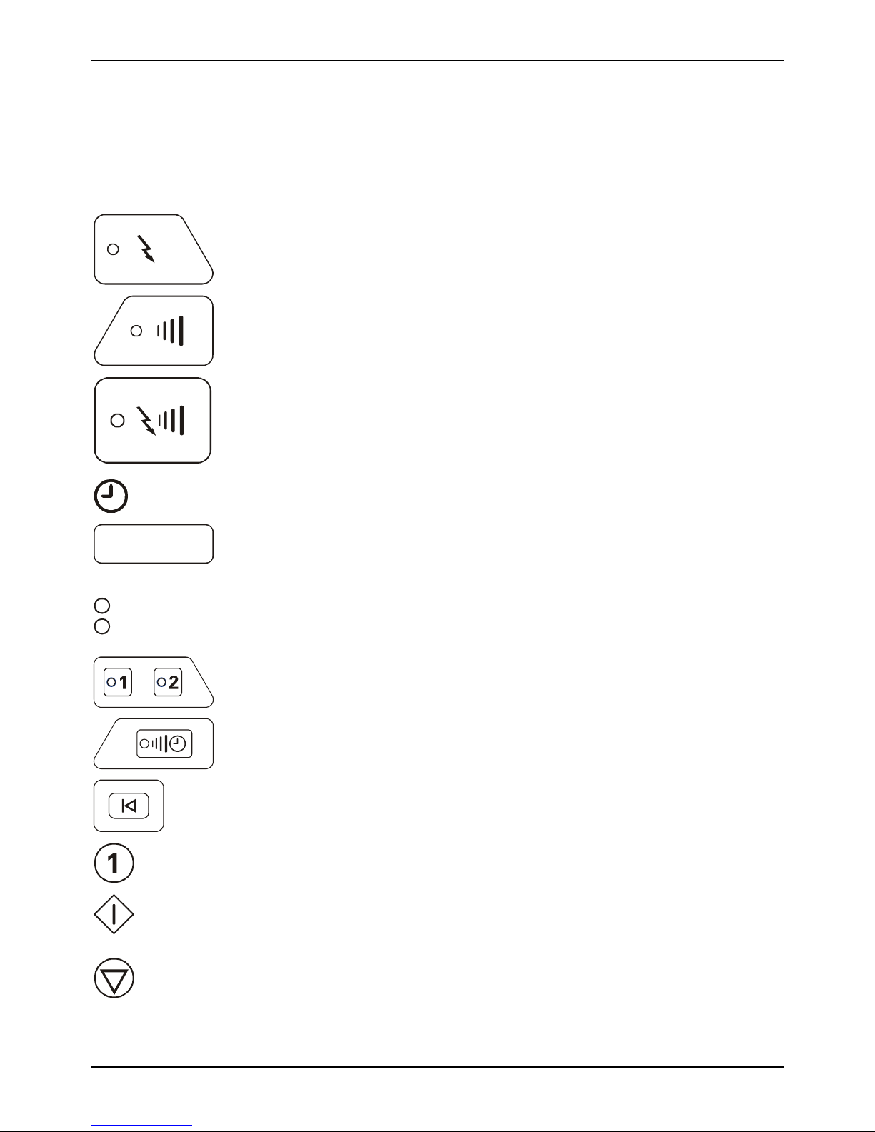
2.1 Symbol Glossary
Stimulation
Electrical Stimulation Selector
Sonicator Plus 930 Instruction Manual— Rev.J_09/13/17
Setup
Ultrasound
Setup
Combination
Setup
00.0
s
Hz
Stimulation
Channels
Ultrasound
Channel
Reset
Setup
Therapeutic Ultrasound Selector
Combination Therapy Selector
Time display
Time display LED’s. Displays treatment time and numeric values for
frequency, on/off times and alphanumeric error codes.
These LED’s will illuminate to prompt the clinician to input either time
in seconds or frequency in Hz. The time or the frequency will be
displayed in the numeric time display.
Stimulation channel display indicator and selector
Ultrasound channel display indicator and selector
Resets treatment parameters and clears treatment setup.
Numeric keypad for time, frequency or phase duration entry.
Starts treatment and stimulation or ultrasound output.
Start
Stops treatment for the treatment displayed in timer window.
Hold
9
Page 10
Mettler Electronics Corp.— Rev.J_09/13/17
m
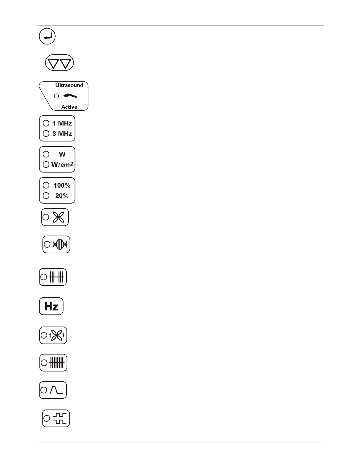
Acts as an “Enter” button during treatment setup.
Enter
Stops all ultrasound and stimulation output.
Stop All Out put
Active ultrasound output indicator on solid when ultrasound output is
present, flashing when coupling is inadequate.
Frequency selector for 5 cm², 1 and 3 MHz applicator.
Ultrasound output display selector
Ultrasound duty cycle selector
Int erferent ial
Premodulated
Mediu
Fre quen cy
Amplitude
M odulation
Continuous
Interferential waveform selector—LED is illuminated when this function
is activated.
Premodulated waveform selector—LED is illuminated when this
function is activated.
Medium frequency waveform selector—LED is illuminated when this
function is activated.
Frequency control selector—Press this button during a stimulation
treatment to display frequency.
Amplitude modulation (Vector rotation), used for interferential
waveform only. LED is illuminated when this function is activated.
Continuous stimulation selector, default selection for any stimulation
treatment. LED is illuminated when this function is activated.
Surge selector to set on and off times. LED is illuminated when this
Surge
Reciprocation
10
function is activated.
Reciprocation selector, use for channel pair 1 & 2. LED is illuminated
when this function is activated.
Page 11
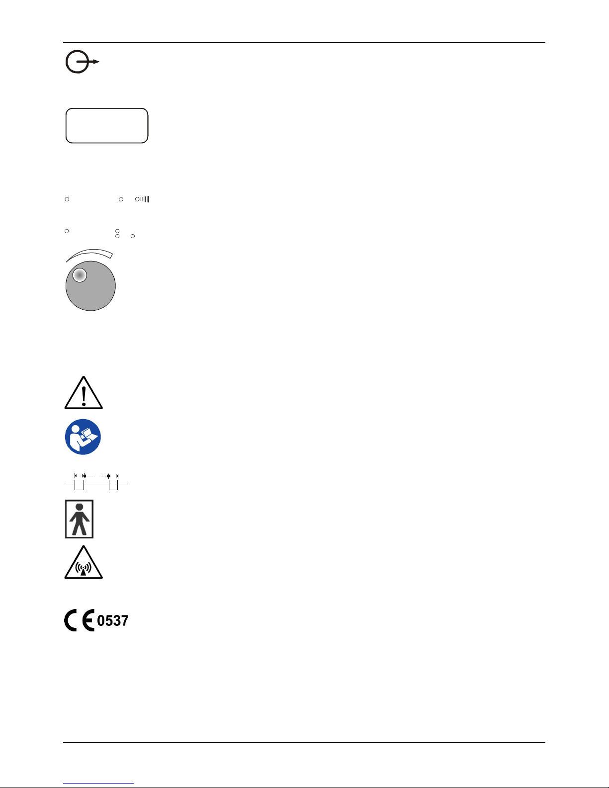
Stimulation or ultrasound output displays
0
W
LED’s that display the output intensity during a treatment. When the
unit is in the “Hold” mode for electrical stimulation, “--- ---“ will be
displayed. When the unit is in the “Hold” mode for therapeutic
00
12
mA
mA
ultrasound, the output intensity will be displayed but the “Active
Ultrasound Output” indicator will be off and the timer will not be
running.
LED indicators are lit to define which output intensity is being
displayed in the two windows.
LED indicators are lit to show the measurement units of the output
intensity being displayed in the window.
2
W/cm
Output intensity control knob, rotate knob clockwise to increase output
and counterclockwise to decrease output.
Sonicator Plus 930 Instruction Manual— Rev.J_09/13/17
I
O
IPX7
Mains On.
Mains Off.
Attention, consult instruction manual.
Symbol for “Consult instructions for use.”
Diagram of Pulsed Mode duty cycles
Type BF Equipment—Class I
Non–ionizing radiation
Protected against the effects of immersion.
CE Mark
11
Page 12

Mettler Electronics Corp.— Rev.J_09/13/17
2.2 List of Abbreviations
cm² — Square centimeters
Hz — Hertz (pulses per second)
LED — Light Emitting Diode
MHz — Megahertz (1 x 10⁶ cycles per second)
s — Microsecond (1 x 10⁻⁶ second)
mA — Milliampere (1 x 10⁻³ ampere)
ms — Millisecond (1 x 10⁻³ second)
min — Minutes
s — Seconds
S/N — Serial Number
W — Watts
W/cm² — Watts per square centimeter
12
Page 13

Sonicator Plus 930 Instruction Manual— Rev.J_09/13/17
Section 3—Installation
3.1 Installation Instructions
1. Connect the line cord to the back of the Sonicator Plus 930. (See Figure 3.1)
2. Plug the line cord (ME 7293) into a grounded wall outlet that is rated between 90–240
VAC, 50–60 Hz. Your power supply must match the voltage requirements listed on the
serial number label of your device. Do not connect the Sonicator Plus 930 to a power
supply rated differently than that described above.
3. The line cord comes equipped with a standard 3–prong plug. This plug provides
grounding for the Sonicator Plus 930. Do not defeat its purpose by using 3–to–2 prong
adapters or any other means of attaching to a wall outlet.
4. Push the hooded, water-proof applicator cable connector (ME 7392) into the round
BNC receptacle located on the front of the Sonicator Plus 930. (See Figure 3.2) Connect
the applicator model 7513 to universal applicator cable using the BNC connector. (See
Figure 3.3). Secure both connectors by lining up the pegs, pushing in all the way and
rotating ¼ turn clockwise. To maintain waterproof characteristics of the BNC
connectors make sure that all connections are dry before attempting to connect them.
5. Place the applicator into the applicator cradle.
6. Plug the electrode cables (ME 2260) into the electrode cable connections as seen in
Figure 3.2. For combination therapy procedures, plug the single line electrode cable
(ME 2261) into the electrode connection for Channel 1.
7. The Sonicator Plus 930 may be susceptible to interference originating from shortwave
diathermy units operating in close proximity to it. Avoid operating the Sonicator Plus
930 adjacent to and simultaneously with operating shortwave devices.
8. Do not use sharp objects to operate the membrane panel switches. If the tough outer
layer of the membrane is broken, moisture may leak into the switches resulting in
switch failure.
9. Once you have verified proper functioning of your Sonicator 740, using the instructions
in Section 4, please register the warranty for your Sonicator Plus 930 on line at
http://www.mettlerelectronics.com/product-registration/.
13
Page 14
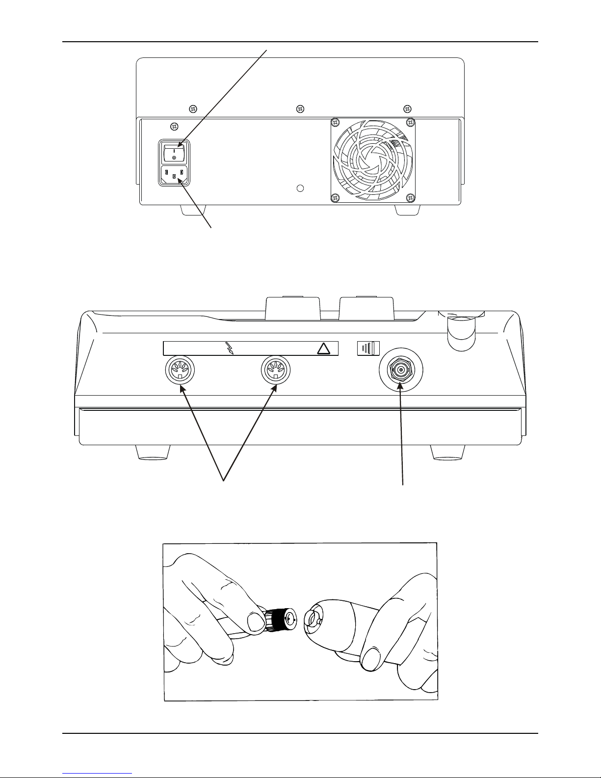
Mettler Electronics Corp.— Rev.J_09/13/17
Mains Power Switch
Line Cord Connection
Figure 3.1— Sonicator Plus 930, Back View—
Mains Power Switch and Line Cord Connection
1 2
Electrode Cable Connections
!
Ultrasound Cable Connection
Figure 3.2— Sonicator Plus 930, Front View—
Electrode Cable and Ultrasound Applicator Connections
Figure 3.3—Connecting the Applicator to the Universal Applicator Cable, line up pegs,
push in all the way and rotate ¼ turn clockwise
14
Page 15
Sonicator Plus 930 Instruction Manual— Rev.J_09/13/17
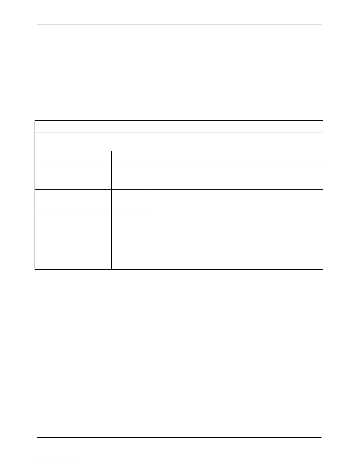
3.2 EMC Guidance
CAUTION: Medical Electrical Equipment needs special precautions regarding Electromagnetic
Compatibility (EMC) and needs to be installed and put into service according to the EMC
information provided in the following tables.
Portable and mobile Radio Frequency (RF) communications equipment can affect Medical
Electrical Equipment.
Accessories: Hospital Medical grade power cord of a maximum length of 120 inches
WARNING: The use of accessories, other than those specified, except those supplied or sold by Mettler
Electronics Corp., Incorporated as replacement parts for internal or external components,
may result in increased EMISSIONS or decreased IMMUNITY of the Sonicator Plus 930.
Guidance and manufacturer’s declaration – electromagnetic emissions
The Sonicator Plus 930 is intended for use in the electromagnetic environment specified below. The
customer or the user of the Sonicator Plus 930 should assure it is used in such an environment.
Emissions Test Compliance Electromagnetic environment-guidance
RF emissions
CISPR 11
RF emissions
CISPR 11
Harmonic emissions
IEC 61000-3-2
Voltage
fluctuations/flicker
emissions
IEC 61000-3-3
Group 1 The Sonicator Plus 930 must emit electromagnetic energy in
order to perform its intended function. Nearby electronic
equipment may be effected.
Class B The Sonicator Plus 930 is suitable for use in all establishments
other than domestic and those directly connected to the public
low-voltage power supply network that supplies buildings
Applicable
Applicable
used for domestic purposes.
15
Page 16

Mettler Electronics Corp.— Rev.J_09/13/17
Guidance and manufacturer’s declaration – electromagnetic immunity
The Sonicator Plus 930 is intended for use in the electromagnetic environment specified below. The
customer or the user of the Sonicator Plus 930 should assure that it is used in such an environment.
Immunity test IEC 60601
test level
Electrostatic
discharge (ESD)
±6 kV contact
±8 kV air
IEC 61000-4-2
Electrical fast
transient/burst
IEC 61000-4-4
±2 kV for power
supply lines
±1 kV for
input/output lines
Surge
IEC 61000-4-5
±1 kV differential
mode
±2 kV common mode
Voltage dips, short
interruptions and
voltage variations
on power supply
input lines
IEC 61000-4-11
<5% U
T
(>95% dip in UT)
for 0.5 cycle
40% UT
(60% dip in U
for 5 cycles
70% U
T
(30% dip in U
for 25 cycles
Compliance level Electromagnetic environment —
guidance
±6 kV contact
±8 kV air
Floors should be wood, concrete or
ceramic tile. If floors are covered with
synthetic material, relative humidity
should be at least 30%.
±2 kV for power
supply lines
±1 kV for
Mains power quality should be that
of a typical commercial or hospital
environment.
input/output lines
±1 kV differential
mode
±2 kV common mode
<5% U
T
(>95% dip in UT)
for 0.5 cycle
40% UT
)
T
(60% dip in U
)
T
for 5 cycles
70% U
)
T
(30% dip in U
T
)
T
Mains power quality should be that
of a typical commercial or hospital
environment.
Mains power quality should be that
of a typical commercial or hospital
environment. If the user of the
Sonicator Plus 930 requires continued
operation during power mains
interruptions, it is needed that the
Sonicator Plus 930 be powered from
an uninterruptible power supply.
for 25 cycles
Power frequency
<5% U
(>95% dip in U
T
)
T
for 5 seconds
3 A/m 3 A/m Power frequency magnetic fields
<5% U
T
(>95% dip in U
for 5 seconds
(50/60 Hz)
magnetic field
IEC 61000-4-8
NOTE UT is the A.C. mains voltage prior to application of the test level.
)
T
should be at levels characteristic of a
typical location in a typical
commercial or hospital environment.
16
Page 17
Sonicator Plus 930 Instruction Manual— Rev.J_09/13/17
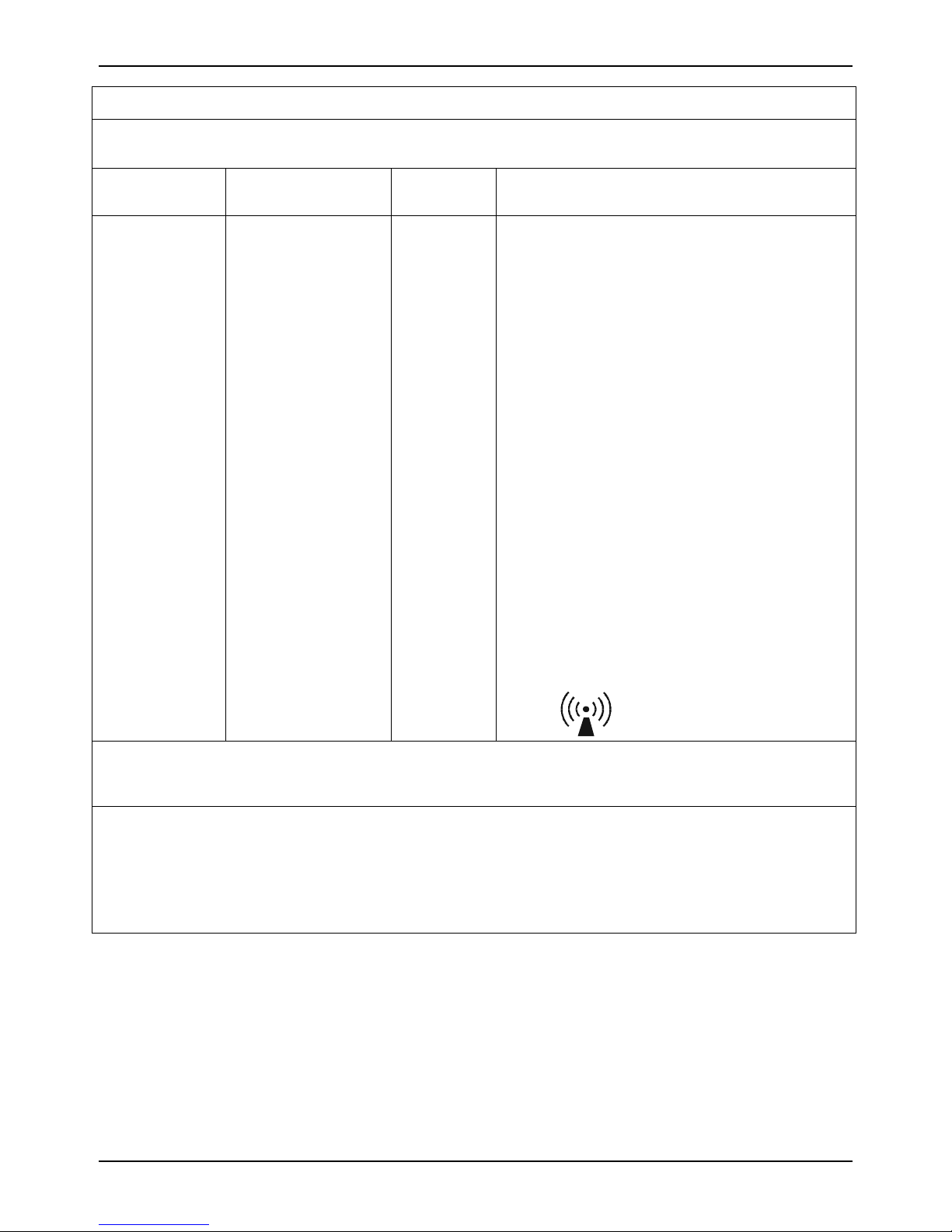
Guidance and manufacturer’s declaration – electromagnetic immunity
The Sonicator Plus 930 is intended for use in the electromagnetic environment specified below. The
customer or the user of the Sonicator Plus 930 should assure that it is used in such an environment.
Immunity test IEC 60601 test level Compliance
level
Conducted RF
IEC 61000-4-6
Radiated RF
IEC 61000-4-3
3 Vrms
150 kHz to 80 GHz
3 V/m
80 MHz to 2,5 GHz
3 V
3 V/m
Electromagnetic environment – guidance
Portable and mobile RF communications
equipment should be used no closer to any part
of the Sonicator Plus 930, including cables, than
the recommended separation distance calculated
from the equation applicable to the frequency of
the transmitter.
Recommended separation distance
d = 1,2√P
d = 1,2√P 80MHz to 800 MHz
d = 2,3√P 800MHz to 2,5 GHz
where P is the maximum output power rating of
the transmitter in watts (W) according to the
transmitter manufacturer and d is the
recommended separation distance in meters (m).
Field strengths from fixed RF transmitters, as
determined by an electromagnetic site survey,
a
should be less than the compliance level in each
frequency range.
b
Interference may occur in the vicinity of
equipment marked with the following symbol:
NOTE 1 At 80 MHz and 800 MHz, the higher frequency range applies.
NOTE 2 These guidelines may not apply in all situations. Electromagnetic propagation is affected by
absorption and reflection from structures, objects and people.
a
Field strengths from fixed transmitters, such as base stations for radio (cellular/cordless) telephones and land mobile radios,
amateur radio, AM and FM radio broadcast and TV broadcast cannot be predicted theoretically with accuracy. To assess the
electromagnetic environment due to fixed RF transmitters, an electromagnetic site survey should be considered. If the measured field
strength in the location in which the Sonicator Plus 930 is used exceeds the applicable RF compliance level above, the Sonicator Plus
930 should be observed to verify normal operation. If abnormal performance is observed, additional measures may be necessary, such
as reorienting or relocating the Sonicator Plus 930.
b
Over the frequency range 150 kHz to 80 MHz, field strengths should be less than 3 V/m.
17
Page 18
Mettler Electronics Corp.— Rev.J_09/13/17
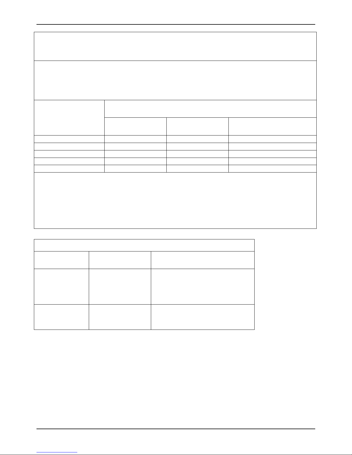
Recommended separation distances between
portable and mobile RF communications equipment and the
Sonicator Plus 930
The Sonicator Plus 930 is intended for use in an electromagnetic environment in which radiated RF
disturbances are controlled. The customer or the user of the Sonicator Plus 930 can help prevent
electromagnetic interference by maintaining a minimum distance between portable and mobile RF
communications equipment (transmitters) and the Sonicator Plus 930 as recommended below, according to
the maximum output power of the communications equipment.
Rated maximum output
power of transmitter
W
0,01 0,12 0,12 0,23
0,1 0,38 0,38 0,73
1 1,2 1,2 2,3
10 3,8 3,8 7,3
100 12 12 23
For transmitters rated at a maximum output power not listed above, the recommended separation distance
d in meters (m) can be estimated using the equation applicable to the frequency of the transmitter, where P
is the maximum output power rating of the transmitter in watts (W) according to the transmitter
manufacturer.
NOTE 1 At 80 MHz and 800 MHz, the separation distance for the higher frequency range applies.
NOTE 2 These guidelines may not apply in all situations. Electromagnetic propagation is affected by absorption and reflection from
structures, objects and people.
150 kHz to 80 MHz
Separation distance according to frequency of transmitter
m
d = 1,2√P
80 MHz to 800 MHz
d = 1,2√P
800 MHz to 2,5 GHz
d = 2,3√P
Guidance and manufacturer’s declaration
No. Mode of Operation Essential Performance
Degradation Allowed
1
2 Unit has two
Unit tested to 230
VAC for CE
Unit tested to 120
VAC for US/Canada
stimulation channels
with ultrasound
18
Unit designed to be failure safe in
abnormal condition
Reset allowed as long as failure safe
Page 19
Sonicator Plus 930 Instruction Manual— Rev.J_09/13/17
A
Section 4—Operating
Instructions
Stimulation/ Ultrasound
Timer Functions
s
00.00 000 000
min
s
R
Hz
R
12
mA
Output
mA
W
W/cm
2
WARNING: Hazardous electrical output. This
equipment is for use by qualified personnel.
Use electrode cable set ME 2260 & ME 2261.
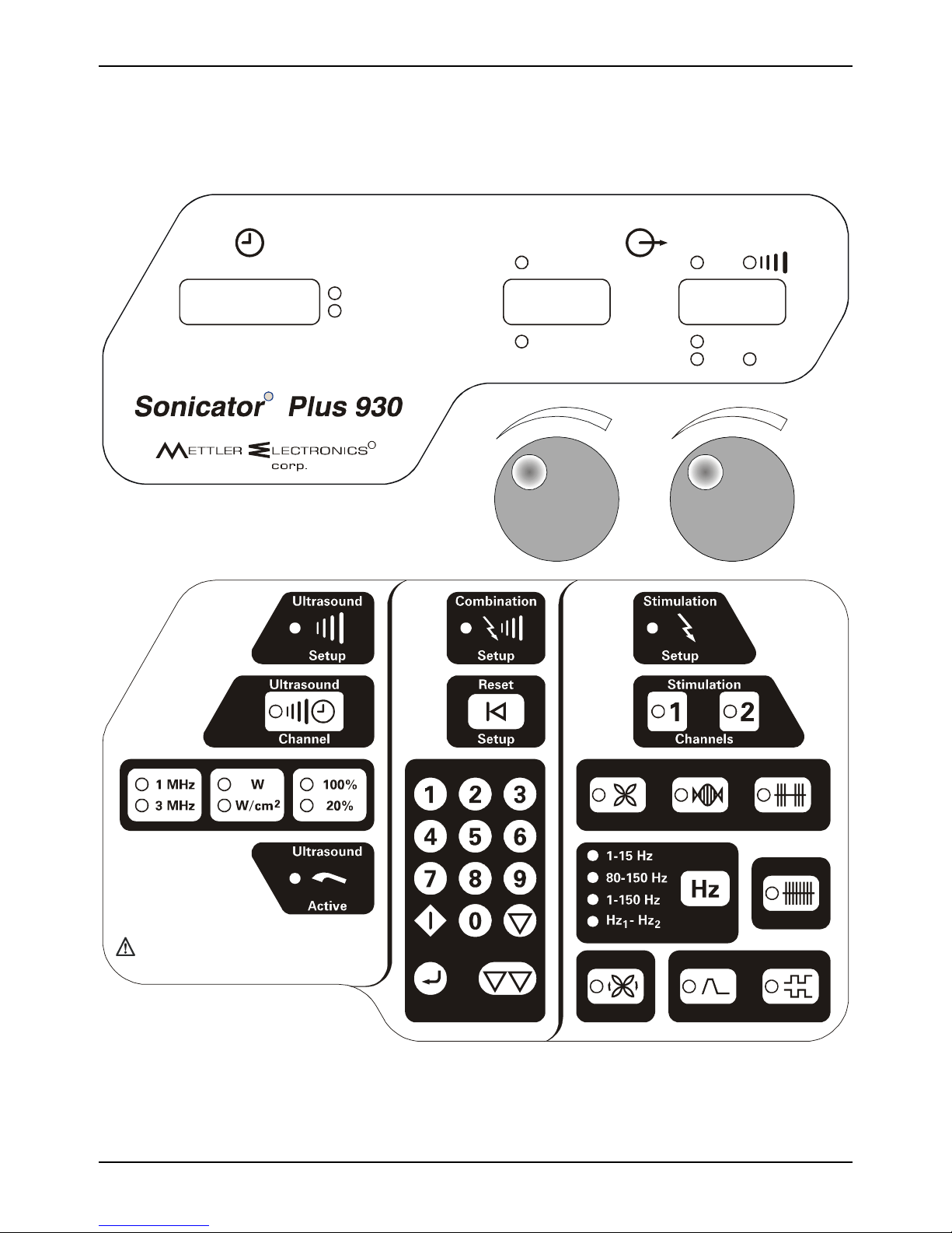
Figure 4.1—Front membrane panel, LED indicators and controls
Start Hold
Stop All Out putEnt er
Medium
FrequencyPremodulatedInt erferential
Cont inuous
Sw eep Frequency
mplitude
M odulation Surge Reciprocation
19
Page 20
Mettler Electronics Corp.— Rev.J_09/13/17
4.1 A Note About Electrodes
To ensure safe operation of the Sonicator Plus 930, follow the recommendations listed
below:
1. We strongly encourage careful maintenance of the electrode system. This includes the
lead wires as well as the pads themselves. Worn cables and/or poor pads (or the
wrong sized pads) can have a significant impact upon treatment results.
2. Do not exceed the number of recommended uses listed on the instructions for V Trodes
or other reusable self–adhesive electrodes.
3. Make sure that the entire surface of the electrode is contacting the patient.
4. Do not use moist hot packs to secure electrodes.
5. To avoid skin irritation due to high current density, do not use electrodes smaller in
surface area than the 2" in diameter V Trode self-adhesive electrode (ME 2702).
6. Do not use conductive carbon electrodes with this product.
7. Whenever clinically possible, utilize the largest possible pads to reduce local increases
in current density. In situations where small pads are required, use the lowest
stimulation intensity necessary to achieve the desired clinical results.
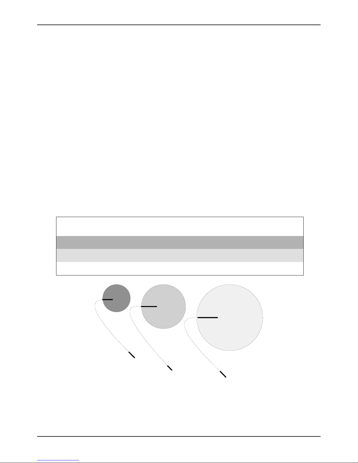
The table below illustrates the relationship between electrode diameter and current
density. As you can see the current density increases rapidly when diameter decreases.
Diameter
inches
Surface Area
Square inches
Current Density
mA/sq in (for 10mA)
1.25 1.2 8.2
2.00 3.1 3.2
3.00 7.1 1.4
1.25 inch
diameter
2.00 inch
diameter
3.00 inch
diameter
Figure 4.2—Electrode Sizes and Current Density
20
Page 21
Sonicator Plus 930 Instruction Manual— Rev.J_09/13/17
4.2 General Operating Instructions:
Before you start.
a) Review precautions, contraindications and side effects/adverse reactions
listed in Section 5.
b) Use Mettler Electronics electrodes to ensure safe and effective operation.
c) Verify connection of the line cord to a grounded wall receptacle and the
Sonicator Plus 930.
d) For ultrasound and combination therapy make sure that the applicator is
securely connected to the applicator cable and the applicator cable is connected
to the Sonicator Plus 930.
e) For combination therapy make sure the single line electrode cable (ME 2261) is
attached to electrode cable connection for Channel 1. For electrical stimulation
connect electrode cables (ME 2260) into the electrode connections for the
channels that are going to be used.
f) Note: Descriptions of the symbols used on controls are in Section 2.
4.3 General Set-up Procedure
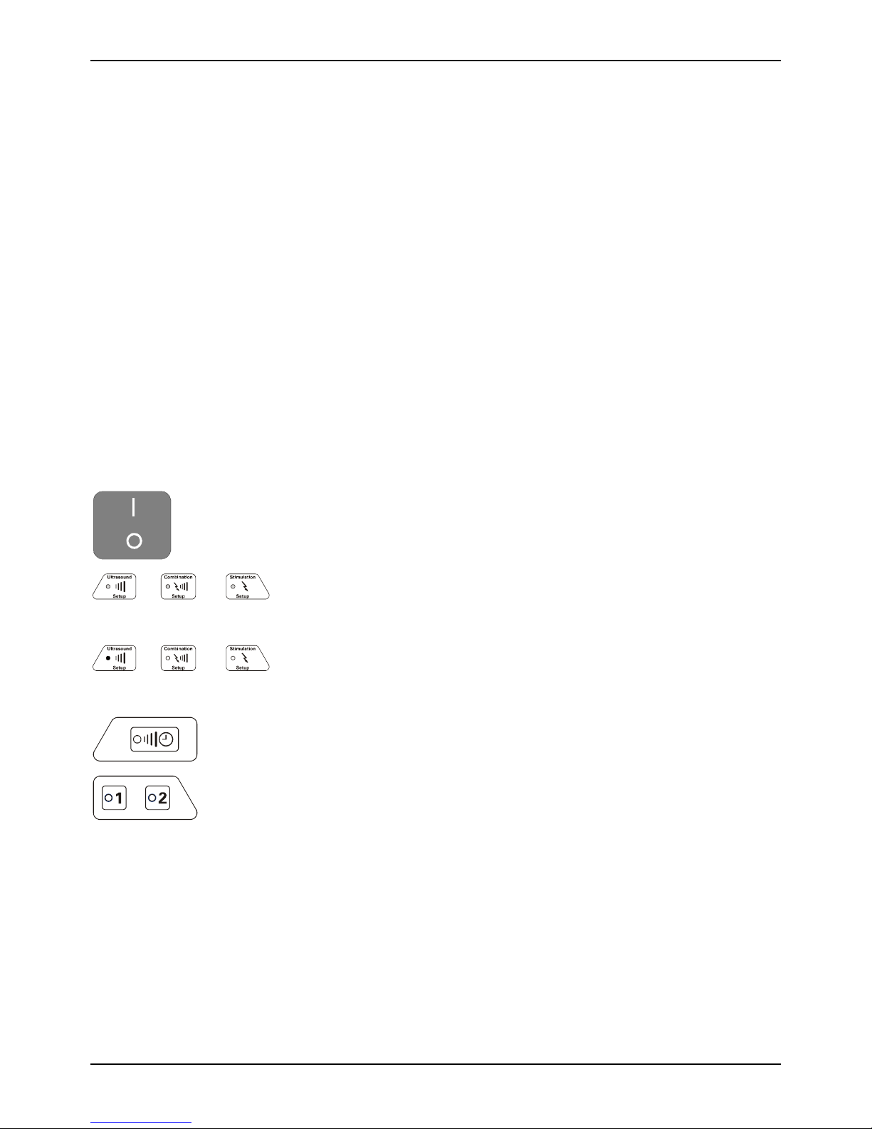
1. Turn on the mains power switch by pressing “I” icon on
switch.
2. When you first turn the Sonicator Plus 930 on, the LED’s for
treatment selectors will flash. NOTE: This is how you will know
what your choices are when setting up a treatment.
3. Select the treatment you wish to perform: Electrical
Stimulation, Ultrasound or Combination Therapy. Return to
this step to begin additional treatment setups.
Ultrasound
Channel
Stimulat ion
Channels
4. The green LED indicators will illuminate for the channel(s) or
ultrasound treatments that will be active for this session.
Indicators will blink for channels that have already been
programmed, but are not being programmed currently.
To view the parameters for a channel, whose indicators are
blinking, press the blinking channel selector button. You will
then be able to view selected treatment parameters, treatment
output and time remaining or elapsed.
5. Set up the various treatment parameters specific to the
treatment you have selected. Details are listed below.
21
Page 22
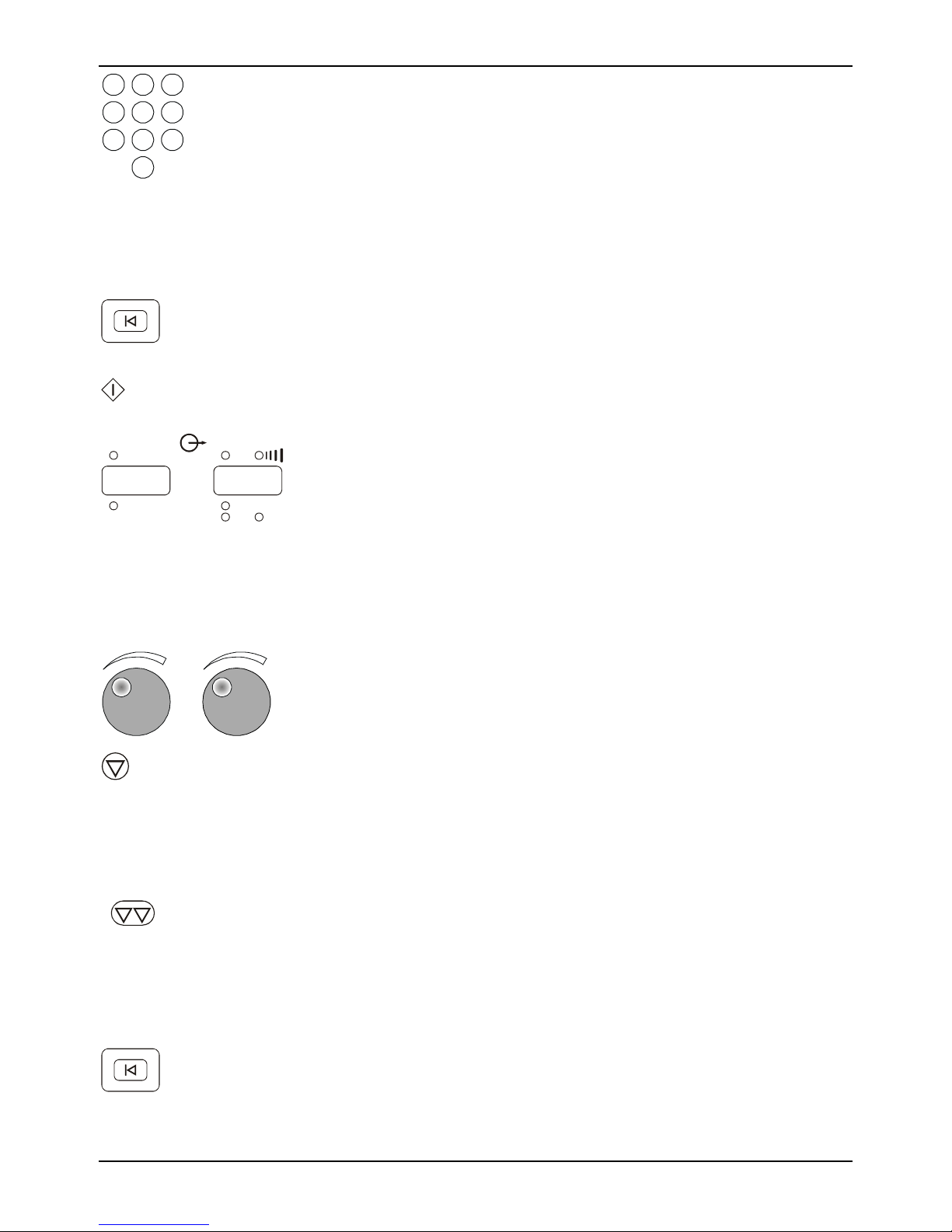
Mettler Electronics Corp.— Rev.J_09/13/17
123
456
6. Select a treatment time using the numeric keypad. For
Ultrasound and Combination Therapy the maximum
treatment time is 30 minutes. For Electrical Stimulation the
789
0
maximum treatment time is 60 minutes. If no treatment time
is input, the timer will continue to run until the maximum
time elapses.
7. For ultrasound and combination therapy apply gel to the
treatment area. For electrical stimulation and combination
therapy apply electrode(s) to the patient as indicated.
Reset
Setup
Start
Stimulat ion/ Ultra sound
12
Output
000 000
mA
mA
W
W/cm
2
8. At any time up until the start key is pressed, the “Reset
Setup” key may be pressed to clear the setup information.
Return to number 2 to restart the setup process.
9. Press the start key to begin treatment.
10. Amber LED indicators for the outputs for electrical
stimulation and ultrasound will illuminate when you start a
treatment. The numeric display shows the output for the
selected channel(s) or ultrasound. The green LED indicators
located below the numeric display indicate the output units.
Flashing amber LED indicators indicate active channel(s)
whose output intensity is not currently displayed. If a
channel is not active, the numeric display will show
“- - -“.
11. Adjust treatment output intensity by rotating the knobs
clockwise to increase output and counterclockwise to
decrease output.
Hold
Stop All O utput
Reset
Setup
22
12. Use this button to stop the treatment output that is currently
being displayed by the Sonicator Plus 930. All treatment
parameters will still be as you programmed them. For
ultrasound, the output intensity will also be remembered. For
stimulation, you will be required to readjust the output
intensity starting at zero if you resume treatment.
13. Use this button to stop all active treatments. Treatment
parameters will still be active so you would be able to resume
treatment at any time. For ultrasound, the output intensity
will also be remembered. For stimulation, you will be
required to readjust the output intensity starting at zero if
you resume treatment.
14. Remove the electrodes from the patient and return them to
their package for storage. Remove gel residue from the
patient’s skin. After the treatment ends, you can press the
“Reset Setup” or the channel selector to free up the channel(s)
for the next treatment selection.
Page 23
Sonicator Plus 930 Instruction Manual— Rev.J_09/13/17
4.4 Stimulation Set-up Procedure
Stimulation
Setup
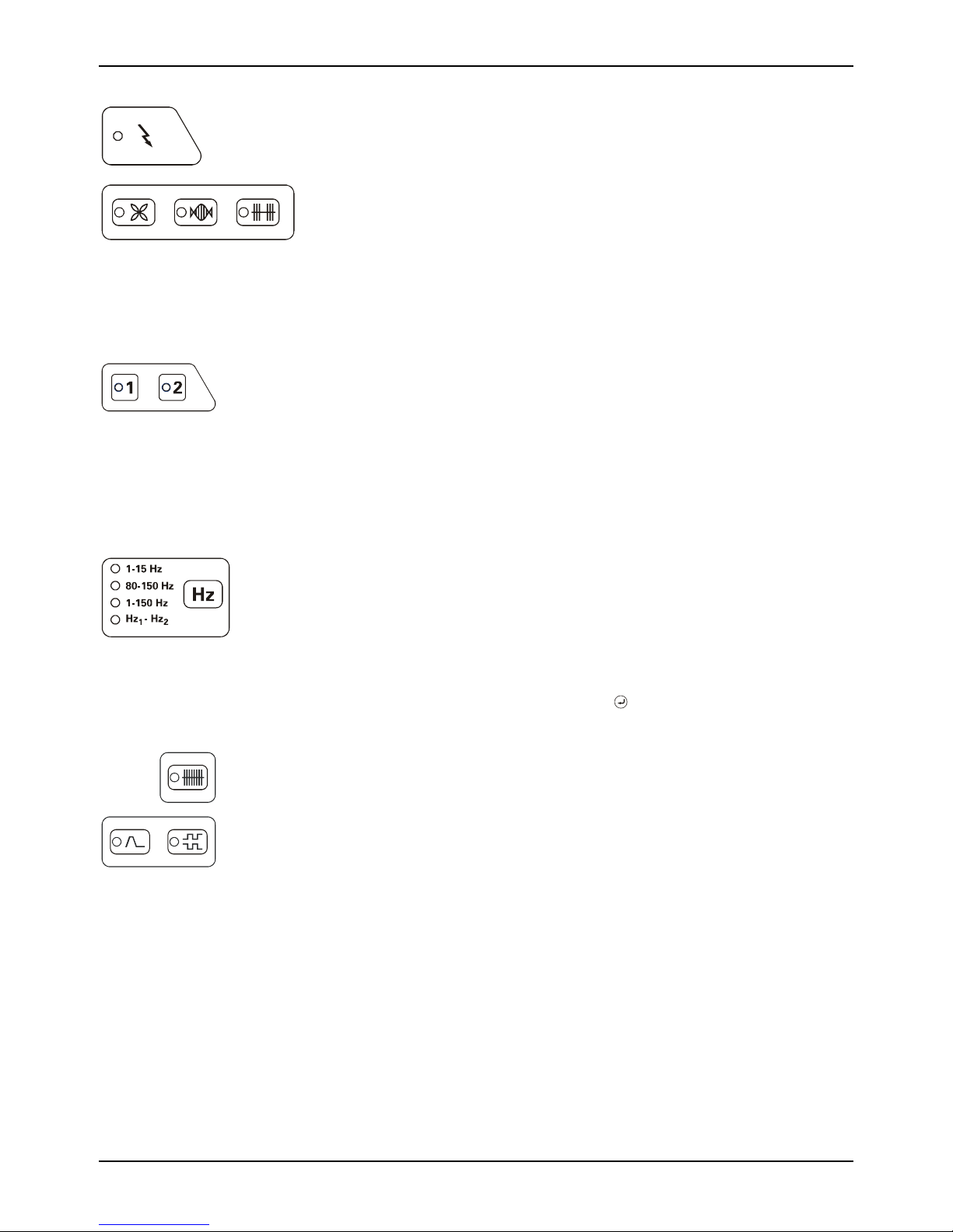
1. Press the stimulation setup key. All the waveform LED’s will
begin to blink. Please note: Start here to begin programming an
additional stimulation treatment setup.
Stimulat ion
Channels
Sweep Frequency
Medium
FrequencyPremodulatedInt erferential
2. Select the stimulation waveform that you would like to use.
Interferential—Channels 1 & 2
Premodulated—Channels 1 or 2
Medium Frequency, Russian waveform— Channels 1 or 2.
Please Note: Up to two different stimulation protocols may
be run simultaneously.
3. For the interferential waveform, the Sonicator Plus 930 will
automatically pick channels 1 & 2. For the premodulated and
medium frequency waveforms, the next available channel will
be selected. If a two-channel treatment is desired pick
Channel 2 by pressing its button. If a channel is already in
use, you will need to free it up before using these two
waveforms. Cancel a treatment setup by pressing the
channel selector.
4. Select frequency options for interferential and premodulated
waveforms.
Choose from preset frequency modulation programs: 1-15,
80-150 or 1-150 Hz or…
Pick Hz1-Hz2 to set your own static frequency or frequency
sweep range. Enter values for each frequency using the
numeric keypad followed by the key. The frequency is
displayed in the timer window and the Hz LED is lit.
Continuous
Surge Reciprocation
5. Set options for amplitude modulation—continuous, surge
and reciprocation.
Continuous—no amplitude modulation, no On/Off times,
default setting, Interferential, Premodulated and Medium
Frequency waveforms.
Surge—Set an On and Off time, 3 seconds Up ramp, 2
seconds Down ramp, Premodulated and Medium Frequency
waveforms.
Reciprocation—Stimulation alternates equally between
Channels 1 & 2, 1 second Up and Down ramps, Premodulated
and Medium Frequency waveforms.
23
Page 24
Mettler Electronics Corp.— Rev.J_09/13/17
1
0
1
Surge Mode—
Surge
0 1 0
s
Hz
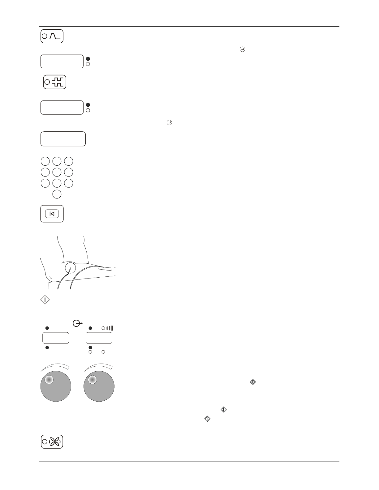
Press Surge selector until you see the On/Off duty cycle that
you would like to use. Press the key to accept the values.
Preset On/Off choices are 5 5, 10 10, 10 30 and 10 50.
Reciprocation Mode—
Reciprocation
1
s
Hz
To setup a Reciprocation program you must have stimulation
set up for two-channel operation. If Channel 1 is lit, press
Channel 2.
Press the Reciprocation key. Enter a value from 2 to 240 and
press the key.
6. Enter the treatment time using the numeric keypad. The
5. 00
123
456
789
smin
maximum treatment time is 60 minutes. If you do not enter a
time, the time will count up during a treatment session, but
will not exceed 60 minutes.
0
Reset
Setup
Start
12
Sti mulat ion/ Ult rasound
Output
00 1 00 1
mA
mA
W
W/cm
2
7. At any time up until the start key is pressed, the “Reset
Setup” key may be pressed to clear the setup information.
Return to number 2 to restart the setup process.
8. Apply the electrodes to the patient. Attach the electrode
cables to the electrodes.
9. Press the start key to begin treatment. The output display will
show 0’s.
10. Adjust the output intensity by turning the knobs clockwise.
The numeric display shows the output in the units indicated
by the lit LED below the display for that channel. Please note:
Adjust the intensity at the peak when the current is on with
an amplitude modulation function. Adjust intensity down
any time during the On time.
NOTE 1: For the surge mode, adjust the output intensity for
the active channels and then press
to start the Surge cycle.
The timer will then begin counting.
NOTE 2: For the reciprocation mode adjust the intensity for
Channel 1 and then press . Then adjust the intensity for
Channel 2 and press
.
Amplitude
M odulation
11. In the interferential mode, press the amplitude modulation
24
(vector rotation) key after the output intensity is adjusted.
Adjust intensity Up only at the peak and Down at any time.
Page 25
Hold
0
Sonicator Plus 930 Instruction Manual— Rev.J_09/13/17
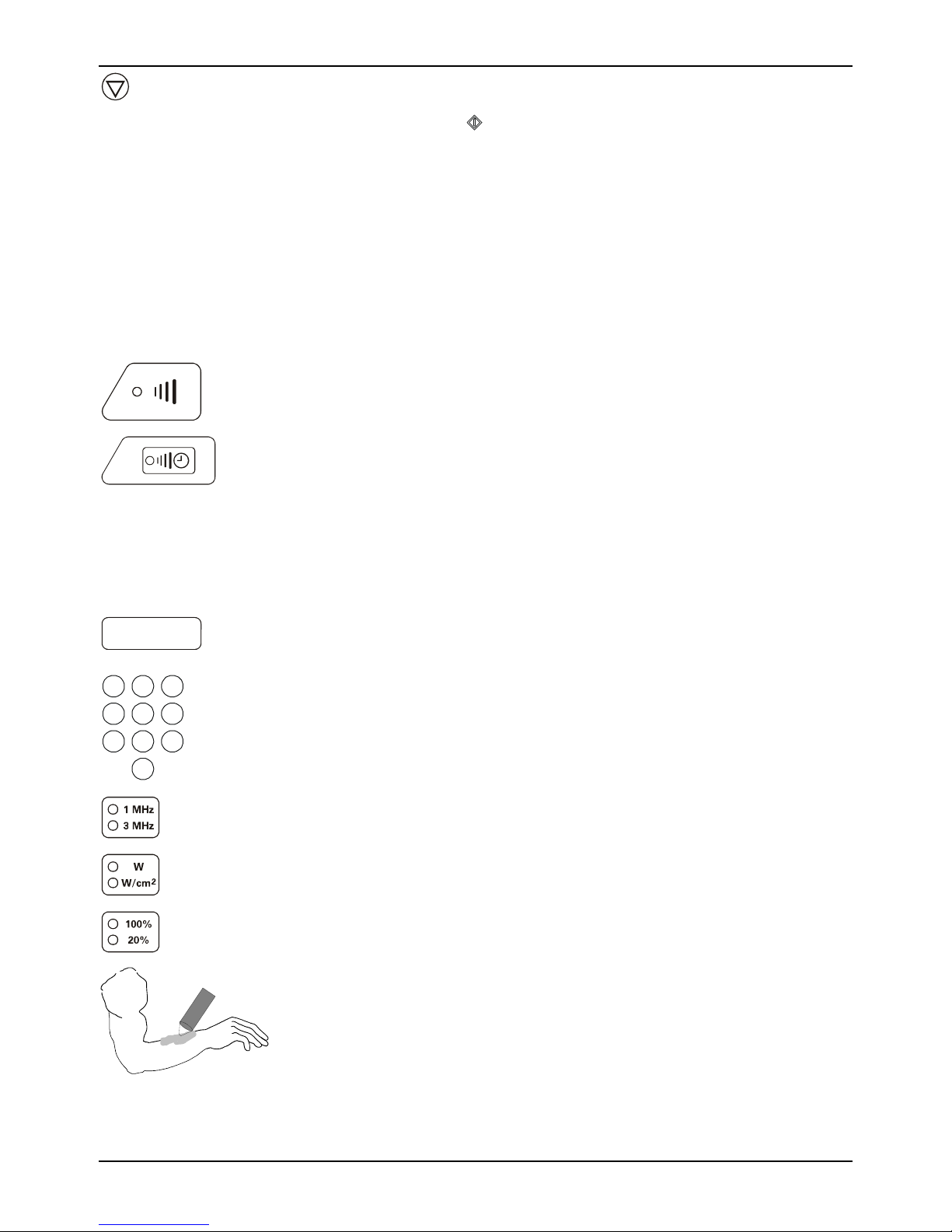
12. Press the “Hold” key to temporarily suspend treatment. All
treatment parameters except output intensity will be
retained. Press to resume treatment and then readjust the
output intensity.
13. After the treatment ends, the output intensity will return to
zero and the output displays show “- - - - - -“. Remove the
electrodes from the patient at this time. After the treatment
ends, you can press the “Reset Setup” or the channel selector
to free up the channel(s) for the next treatment selection.
4.5 Ultrasound Set-up
Procedure
Ultrasound
Setup
Ultrasound
Channel
0 5. 0
smin
123
1. Press the ultrasound setup key.
2. The green LED indicator will illuminate for the ultrasound
treatment. Indicators will blink for channels that have already
been programmed, but are not being programmed currently.
To view the parameters for a channel, whose indicators are
blinking, press the selector button. You will then be able to
view selected treatment parameters, treatment output and
time remaining or elapsed.
2. Input treatment time. The maximum treatment time is 30
minutes. If you do not input time the timer will display
elapsed time during the treatment and stop at 30 minutes.
456
789
0
3. Press this key to select the output frequency.
4. Press this key to select either Watts or Watts/cm² for the
output display.
5. Select the duty cycle for the ultrasound from continuous
(100%) or pulsed (20%).
6. Apply a layer of Sonigel (ultrasound couplant gel or lotion) to
the treatment area.
25
Page 26
Mettler Electronics Corp.— Rev.J_09/13/17
Ultrasound
Couplant
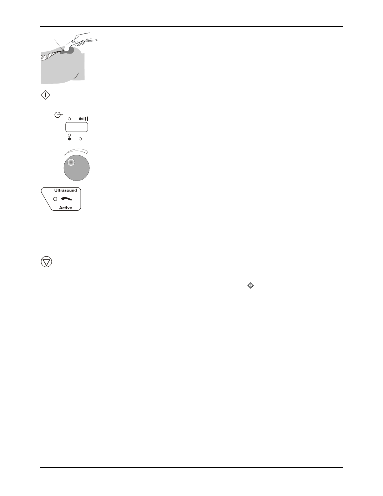
7. Couple the applicator to the treatment area by keeping the
entire surface of the applicator in contact with the gel that has
been applied to the patient. This will ensure efficient delivery
of therapeutic ultrasound to the patient.
8. Press the start key to begin treatment.
Start
Stim ulation/ Ult rasound
Output
05. 0
2
mA
W
W/cm
2
9. Adjust the ultrasound power to the desired output intensity,
by turning the control knob clockwise to increase intensity
and counter-clockwise to decrease it. Remember to couple the
applicator to the patient while adjusting ultrasound power.
The amber LED marked for ultrasound will indicate that
ultrasound is being generated.
10. If the applicator is not in contact with the patient or
ultrasound is not being efficiently transmitted to the patient,
the LED in the symbol pictured to the left will blink. If
inadequate coupling occurs for more that 30 continuous
seconds the Sonicator Plus 930 will automatically stop
ultrasound output, beep twice and display “E002” in the time
display.
Hold
11. If you need to temporarily stop treatment press the hold
button pictured on the left. Remaining treatment time and
selected output power are displayed. Ultrasound power will
stop. To resume treatment, press .
12. Notes on coupling: Failure to efficiently transmit therapeutic
dosages of ultrasound to the patient can be caused by the
following:
a) Treatment of an irregular area where it is impossible to
keep the applicator surface in contact with the gelled
patient area. In this case you can try to use a little more
gel or perform underwater treatment, if the treatment
area is submersible in water.
b) An inappropriate couplant is being used. Only materials
that efficiently transmit ultrasound should be used for
therapeutic ultrasound applications. Some creams and
oil-based preparations are not efficient ultrasound
couplants. If you use these materials the coupling
indicator LED may blink and E002 may be displayed.
c) Areas of heavy body hair will trap air beneath the hair
and prevent ultrasound transmission. Shaving the
treatment area prior to treatment or thoroughly wetting
26
Page 27
Sonicator Plus 930 Instruction Manual— Rev.J_09/13/17
0
the area prior to the application of couplant will result in
more efficient transmission of ultrasound.
13. When the set treatment time has elapsed, the unit beeps three
times. Time and ultrasound power displays will display “0”
and ultrasound power will turn off. After the treatment ends,
you can press the “Reset Setup” or the ultrasound channel
selector to free up the channel(s) for the next treatment
selection.
4.6 Combination Therapy Set-up Procedure
Combination
Setup
Stimulat ion
Channels
Ultrasound
Channel
Medium
FrequencyPremodulated
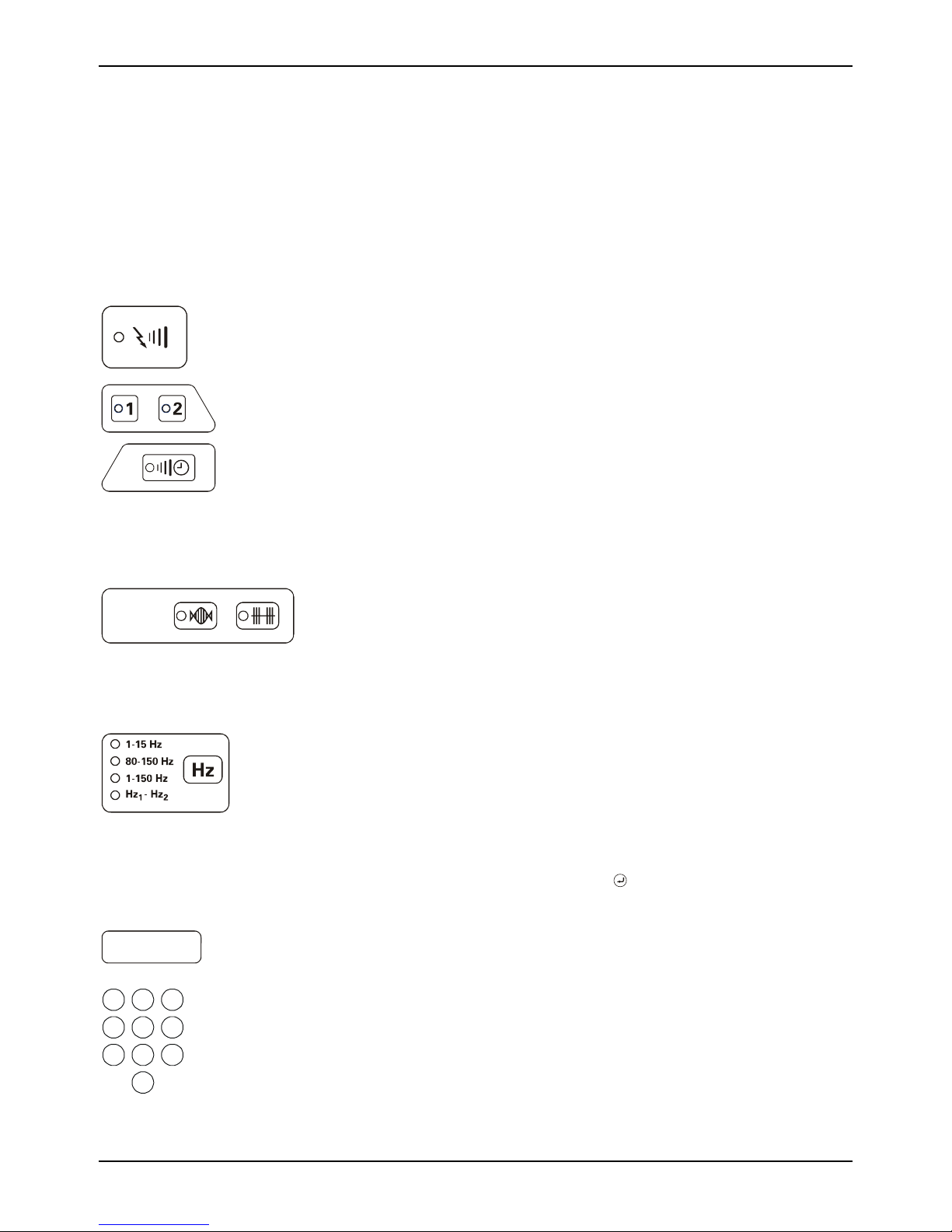
1. Press the combination setup key. LED’s for Premodulation
and Medium Frequency will begin to blink.
2. The green LED indicators will illuminate for the ultrasound
treatment and Channel 1. Indicators will blink for channels
that have already been programmed, but are not being
currently displayed.
To view the parameters for a channel, whose indicators are
blinking, press the selector button. You will then be able to
view selected treatment parameters, treatment output and
time remaining or elapsed.
3. Select the stimulation waveform that you would like to use.
Premodulated
Medium Frequency, Russian waveform
Please Note: Combination therapy is available with Channel 1
only.
Sweep Frequency
0 5. 0
123
456
789
0
4. Select frequency options for interferential and premodulated
waveforms.
Choose from preset frequency modulation programs: 1-15,
80-150 or 1-150 Hz or…
Pick Hz1-Hz2 to set your own static frequency or frequency
sweep range. Enter values for each frequency using the
numeric keypad followed by the
key. The frequency is
displayed in the timer window and the Hz LED is lit.
5. Input treatment time. The maximum treatment time is 30
smin
minutes. If you do not input time the timer will display
elapsed time during the treatment and stop at 30 minutes.
27
Page 28
Mettler Electronics Corp.— Rev.J_09/13/17
6. Press this key to select the output frequency.
7. Press this key to select either Watts or Watts/cm² for the
output display.
8. Select the duty cycle for the ultrasound from continuous
(100%) or pulsed (20%).
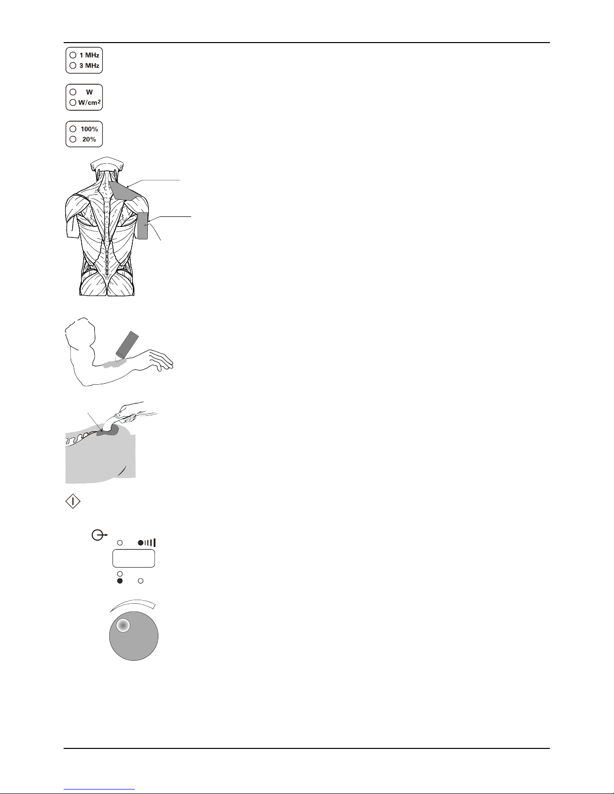
9. Apply the dispersive electrode to the patient. Plug the single
Ultrasound + Stimulation
Application
electrode cable (ME 2261) into channel one. Plug the electrode
into the single electrode cable or the red end of a regular
Dispersive Electrode
electrode cable (ME 2260). WARNING: Apply the dispersive
electrode in such a manner to prevent transthoracic
stimulation.
10. Apply a layer of Sonigel (ultrasound couplant gel) to the
treatment area. Please note: the couplant must also be electrically
conductive for combination therapy.
Ultrasound
Couplant
Start
Stimulat ion/Ul trasound
Output
05. 0
2
mA
W
W/cm
11. Couple the applicator to the treatment area by keeping the
entire surface of the applicator in contact with the gel that has
been applied to the patient. This will ensure an efficient
delivery of therapeutic ultrasound to the patient.
12. Press the start key to begin treatment.
13. Adjust the ultrasound power to the desired output intensity,
by turning the control knob clockwise to increase intensity
and counter-clockwise to decrease it. Remember to couple the
2
applicator to the patient while adjusting ultrasound power.
The amber LED marked for ultrasound will indicate that
ultrasound is being generated.
28
Page 29
Stim ulation/ Ult rasound
1
00 1
mA
Hold
Output
Sonicator Plus 930 Instruction Manual— Rev.J_09/13/17
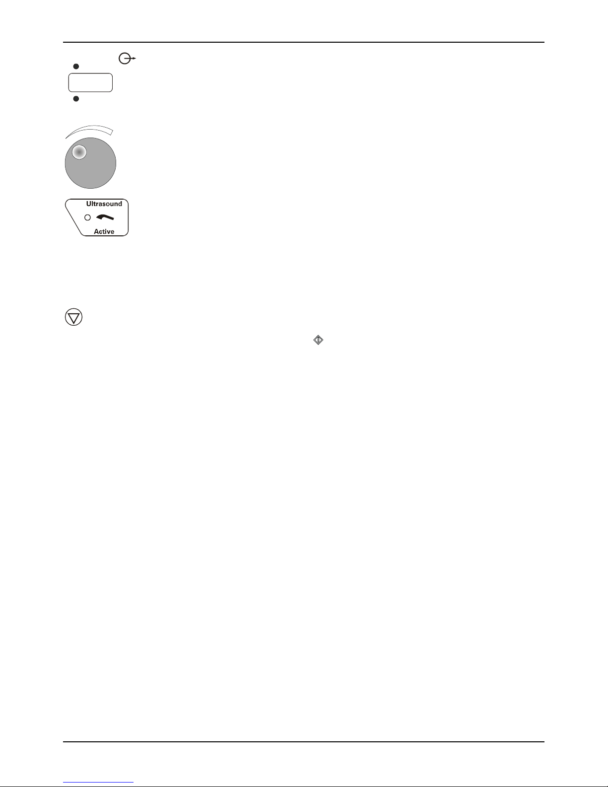
14. Adjust the stimulation output to the desired output intensity
by turning the control knob clockwise to increase intensity
and counter-clockwise to decrease it.
15. If the applicator is not in contact with the patient or
ultrasound is not being efficiently transmitted to the patient,
the LED in the symbol pictured to the left will blink. If
inadequate coupling occurs for more that 30 continuous
seconds the Sonicator Plus 930 will automatically stop
ultrasound output, beep twice and display “E002” in the time
display.
16. Press the “Hold” key to temporarily suspend treatment. All
treatment parameters except stimulation output intensity will
be retained. Press to resume treatment and then readjust
the stimulation output intensity.
17. At the end of a treatment the output intensity will return to
zero and the output displays show “- - - 000“. Remove the
electrodes from the patient at this time. Wipe any gel residue
from the patient’s skin. After the treatment ends, you can
press the “Reset Setup” for either the ultrasound channel or
channel one selector to free up the channel(s) for the next
treatment selection.
29
Page 30
Mettler Electronics Corp.— Rev.J_09/13/17
4.7 Electrode Positioning
1. General information
Placement of electrodes may be by the quadpolar,
bipolar or monopolar techniques. Proper positioning
and contact will insure treatment comfort and
efficiency. Electrodes should never be placed in such
a manner as to produce current flow through the
cardiac area. For safe operation of the Sonicator Plus
930, review contraindications, warnings, precautions
and Side Effects/Adverse Reactions in sections 5.4,
5.5, 5.7 and 5.8 before positioning electrodes.
2. Preparation of the skin prior to electrode application
To insure the efficient current conduction necessary
for proper treatment, certain preparations must be
made. Cleaning or wetting should eliminate any
impairment to current conduction on the patient’s
skin such as an oily or dry surface, or excessive hair
coverage. Shaving may be necessary depending upon
the density of hair coverage. Failure to provide for
maximum current conduction efficiency could result
in skin irritation relating to an increase in current
density at the electrode site.
Using reusable electrodes for longer periods of time
than those recommended by the package insert could
result in ineffective treatments or cause skin irritation.
Care should be taken to ensure application of the total
electrode surface area to the patient's skin prior to
commencing treatment.
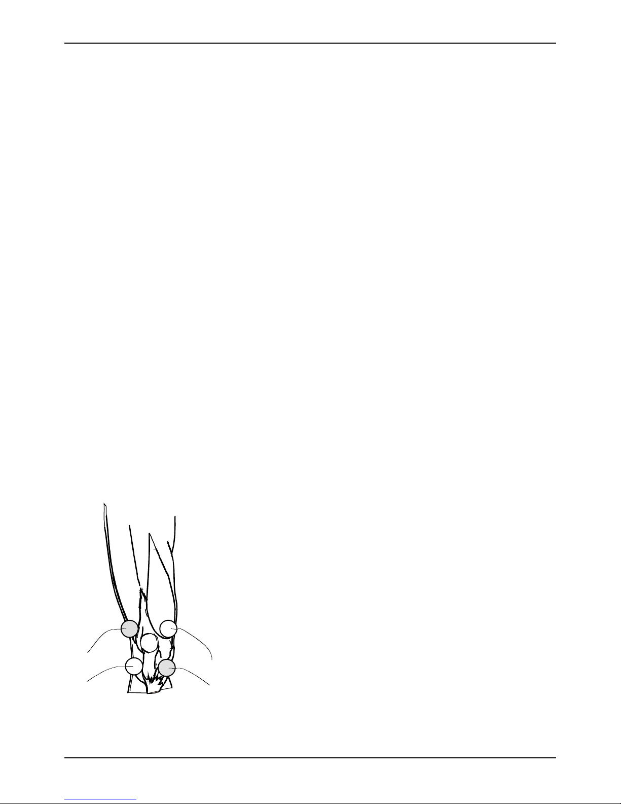
3. Quadpolar electrode application technique
Figure 4.3—Quadpolar Electrode
Placement
Technique
30
Quadpolar techniques should be used with the
“Interferential” waveform. The electrodes from
Channel 1 are placed diagonally from each other.
While the electrodes from Channel 2 are placed
diagonally across from each other to form an “X” over
the treatment area. The zone of maximum
interference between the two channels occurs roughly
in the center of the “X”.
Constantly changing the intensity levels of the two
channels will change the interference pattern felt by
the patient. Pressing the amplitude modulation key
will constantly change the intensity of the outputs of
the two channels during treatment, increasing the
area covered by the interference pattern.
Page 31
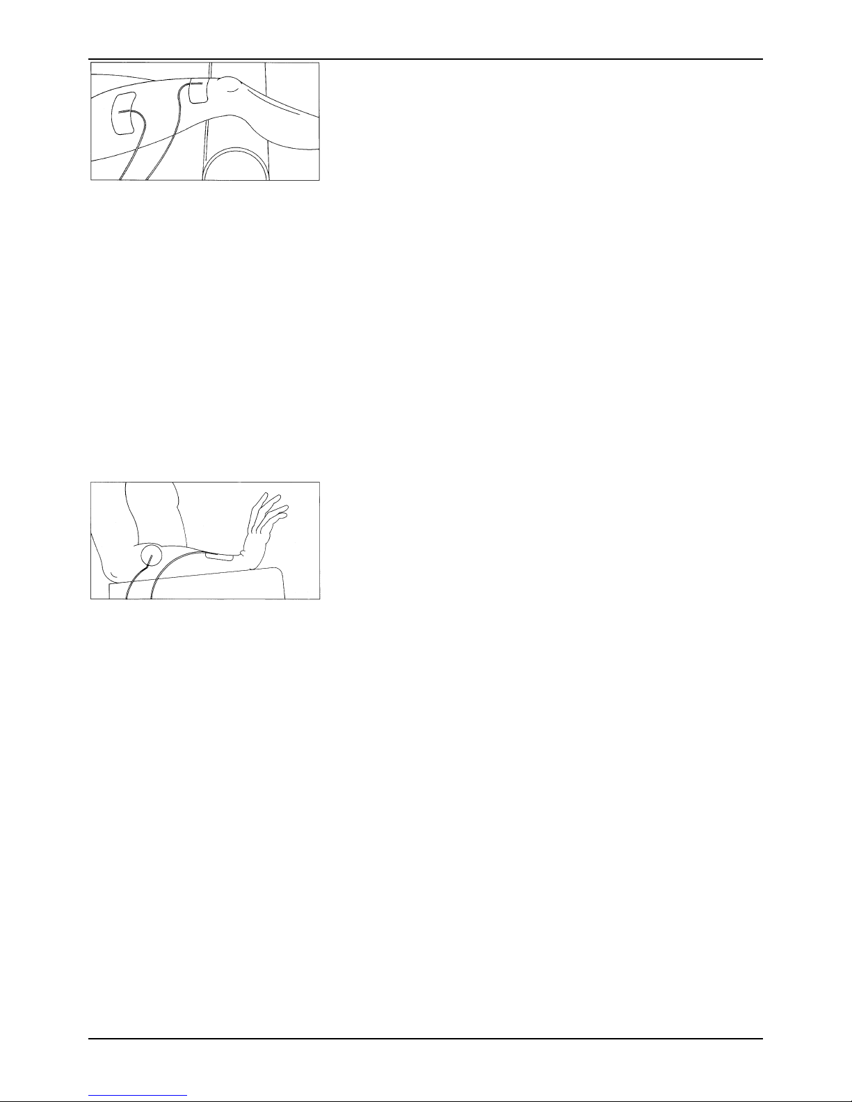
Figure 4.4—Bipolar Electrode
Placement Technique
Sonicator Plus 930 Instruction Manual— Rev.J_09/13/17
4. Bipolar electrode placement techniques
Bipolar electrode placement techniques should be
used to provide stimulation to larger muscle groups,
such as the quadriceps or the hamstrings. The
symmetrical waveforms of the “Premodulated”and
“Medium Frequency” waveforms are usually applied
to the body using the bipolar technique.
Equal size electrodes are placed at each end of the
muscle or muscle group. Current concentration is
over the entire length of that muscle or muscle group
and especially effective on weak musculature.
Electrode placement should be at opposite ends of the
limb or muscle group. Care should be taken to insure
that electrodes are not placed too close together which
could produce current concentration along the edges
of the pads. This is the so-called “edging effect”
which can cause patient discomfort. The figure on the
left shows a pad set up for stimulation of the quadriceps.
Figure 4.5—Monopolar
Electrode Placement
Technique
5. Monopolar electrode application techniques
Monopolar techniques may be used with the
“Premodulated”and “Medium Frequency”
waveforms. The smaller, active, electrode is placed
over the muscle motor point. In treatments designed
to relieve pain, the active electrode is placed over the
painful area. The larger, dispersive, electrode is
placed on the same side of the body at some point
distal to the active electrode. The dispersive pad is
generally three to four times larger than the active
electrode so that current density is too low to cause
muscle contractions under the dispersive electrode.
Never place the dispersive electrode over the
antagonist muscle.
The monopolar electrode placement technique has
been found to be especially useful for muscle
stimulation of the upper extremities and small muscle
groups. This technique helps concentrate the
stimulation effect on the muscle under the smaller
electrode. The figure on the left illustrates one
possible electrode placement for muscle stimulation
of the forearm.
31
Page 32
Mettler Electronics Corp.— Rev.J_09/13/17
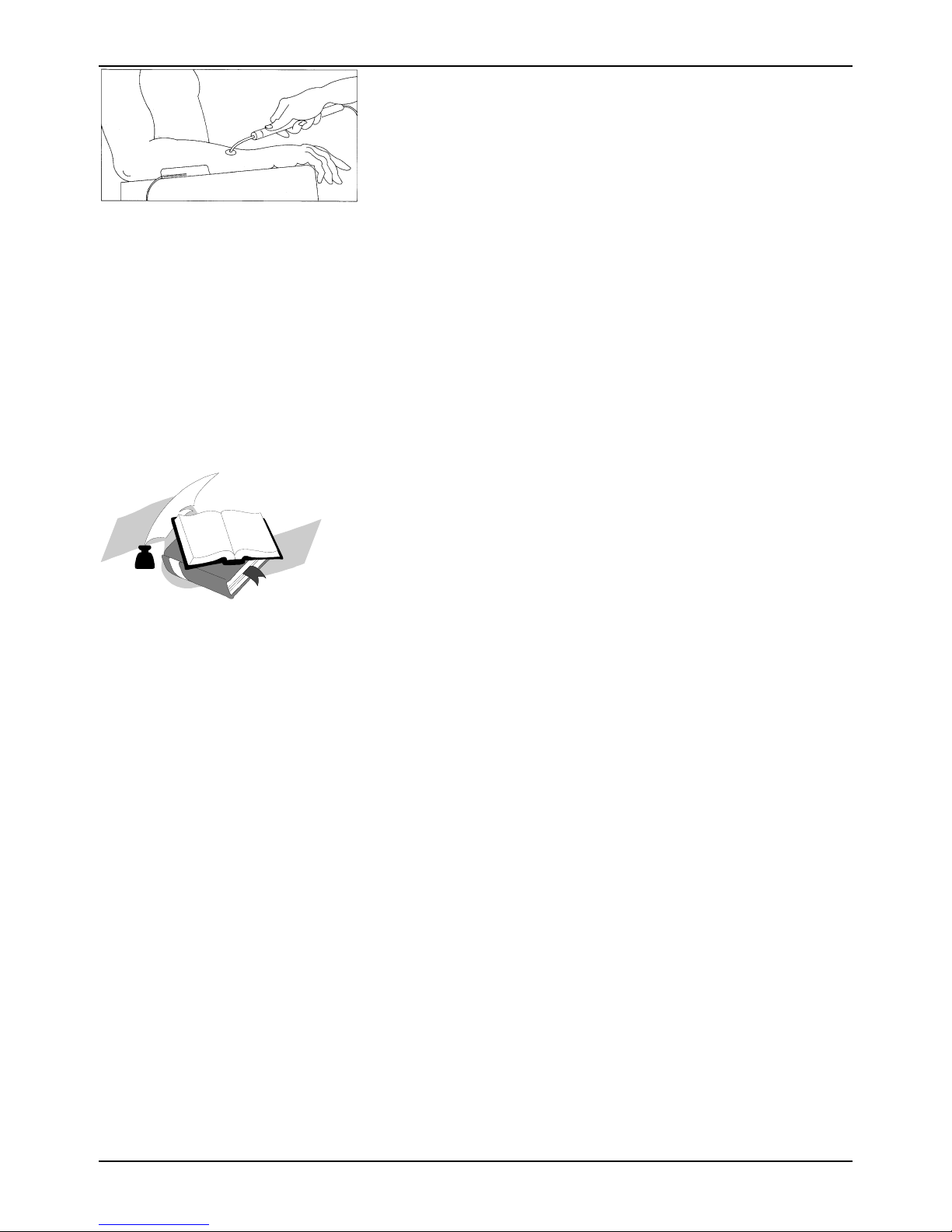
6. Using the pencil electrode
Figure 4.6—Using the Pencil
Electrode
7. Additional information about electrode placement:
The pencil electrode is used for the stimulation of
small muscles or painful areas. It is also useful to help
identify the exact motor point of a muscle or muscle
group. The pencil electrode may be used with the
“Premodulated”or “Medium Frequency” waveforms.
Attach the pencil electrode to the black electrode cable
using a pin to banana adapter. Attach the red
electrode cable to a dispersive pad. Apply dispersive
electrode in such a manner to prevent transthoracic
stimulation
Pressing the switch located on the pencil electrode
will allow treatment currents to be delivered to the
patient. Four tips of different sizes are included with
the pencil electrode. The figure on the left shows an
application of the pencil electrode.
Motor point charts are available as guides from
Mettler Electronics Corp. These points may vary from
patient to patient, and at time of injury, may vary in
the same patient. The Electrical Stimulation and
Ultrasound Pocket Guide II by Michelle Cameron is
available.
32
Page 33

Sonicator Plus 930 Instruction Manual— Rev.J_09/13/17
Section 5—Indications,
Contraindications, Precautions
and Adverse Reactions
5.1 Indications for Therapeutic Ultrasound
Ultrasound delivered to the body using an efficient couplant provides deep heating effects
to body tissues. Ultrasound delivered at a frequency of 1 MHz penetrates to a depth of
approximately 5 centimeters while ultrasound at a frequency of 3 MHz penetrates tissue to
a depth of approximately 1–2 cm.
When therapeutic ultrasound is delivered to the body at intensities capable of generating a
deep tissue temperature increase, some or all of the following effects may occur:
1. Pain relief
2. Reduction of muscle spasm
3. Localized increase in blood flow
4. Increase range of motion of contracted joints using heat and stretch techniques.
5.2 Indications for Neuromuscular Electrical Stimulation
The application of pulsating electric currents to the body via electrodes elicits responses
from nerves, which conduct pain sensation and muscle contraction information.
Stimulation of sensory fibers will help block pain while the stimulation of motor fibers will
generate pulsatile contractions of the muscle groups innervated by the nerves being
stimulated.
Based on this information, some of the indications for use are as follow:
1. Symptomatic relief of chronic intractable pain, acute post traumatic pain or acute post
surgical pain (Interferential and Premodulated waveforms)
2. Temporary relaxation of muscle spasm
3. Prevention of post–surgical phlebo–thrombosis through immediate stimulation of calf
muscles
4. Increase of blood flow in the treatment area
5. Prevention or retardation of disuse atrophy in post–injury type conditions
6. Muscle re–education
7. Maintaining or increasing range of motion
33
Page 34

Mettler Electronics Corp.— Rev.J_09/13/17
5.3 Contraindications for Therapeutic Ultrasound
1. Therapeutic ultrasound should not be applied over the pregnant or potentially
pregnant uterus. Therefore, therapeutic ultrasound should not be applied over the
uterus unless specific assurance can be attained from the patient that she is not
pregnant.
2. Patients who have cardiac pacemakers should be protected from direct ultrasound
exposure over the thorax to protect the lead wires and pacer from such exposure.
3. Therapeutic ultrasound should not be applied to the eye.
4. Applications of therapeutic intensities of ultrasound should be avoided over the heart.
5. Neoplastic tissues or space occupying lesions should not be exposed to ultrasound.
6. Ultrasound should not be applied to the testes to avoid increases in temperature.
7. Areas of thrombophlebitis should not be treated with therapeutic ultrasound due to
the increased possibility of clotting or dislodging a thrombus. Conditions where this
might occur are deep vein thrombosis, emboli and severe atherosclerosis.
8. Tissues previously treated by deep x–ray or other radiation should not be exposed to
therapeutic ultrasound.
9. Ultrasonic treatment over the stellate ganglion, the spinal cord after laminectomy,
subcutaneous major nerves and the cranium should be avoided.
10. Do not treat ischemic tissues in individuals with vascular disease where the blood
supply would be unable to follow the increase in metabolic demand and tissue
necrosis might result.
11. Ultrasound should not be applied over the epiphyseal areas (bone growth centers) of
the bones of growing children.
5.4 Contraindications for Neuromuscular Electrical
Stimulation
1. Electrical neuromuscular stimulation should not be administered to individuals who
are or may be pregnant.
2. Do not stimulate a patient who has a cardiac demand pacemaker.
3. Patients with implanted electronic devices should not be subjected to stimulation.
4. Placement of electrodes across the chest laterally or anterior/posterior creates a
possible hazard with cardiac patients and is therefore not recommended. Do not use
transthoracically in any mode. Great care should be exercised in applying the electrical
stimulus current to any region of the thorax because the stimulus current may produce
cardiac arrhythmia. In patients with known heart disease, electrical stimulation should
be used only after careful physician evaluation and patient instruction.
5. Place electrodes in such a way to avoid stimulation of the carotid sinus (neck) region.
6. Patients with arterial or venous thrombosis, or thrombophlebitis are at risk of
developing embolisms when electrical stimulation is applied over or adjacent to the
34
Page 35

Sonicator Plus 930 Instruction Manual— Rev.J_09/13/17
vessels containing the thrombus. If a patient has a history of deep vein thrombosis,
even many years past, the affected area should not be stimulated.
7. Do not use over swollen, infected, or inflamed areas. Do not place electrodes over skin
eruptions.
8. Fresh fractures should not be stimulated in order to avoid unwanted motion.
9. Do not apply stimulation transcerebrally (through the head).
10. Do not use on cancer patients.
11. Stimulation should not be applied immediately following trauma or to tissues
susceptible to hemorrhage.
12. Positioning electrodes over the neck or mouth may cause severe spasm of the
laryngeal or pharyngeal muscles. These contractions may be strong enough to close
the airway or cause difficulty in breathing.
13. Do not apply stimulation for undiagnosed pain syndromes, until etiology is
established.
14. Do not apply electrodes directly over the eyes or inside body cavities.
15. Do not use electrical stimulation in conjunction with high frequency surgical
equipment or microwave therapy systems.
5.5 Warnings for Neuromuscular Electrical Stimulation
1. Electrical stimulation is ineffective for pain of central origin.
2. Electrical stimulation must be applied by a physician or other qualified practitioner
and should be used for only the prescribed purposes.
3. Electrical stimulation is of no curative value.
4. Electrical stimulation is a symptomatic treatment and as such suppresses the sensation
of pain, which could serve as a protective mechanism.
5. The safety of electrical stimulators for use on children has not been determined. Keep
out of reach of children.
6. Electronic monitoring equipment (such as ECG monitors and ECG alarms) may not
operate properly when electrical stimulation is in use.
5.6 Precautions for Therapeutic Ultrasound
1. Ultrasound should not be applied in areas of reduced sensation or circulation. Patients
having reduced sensation will not be able to notify the practitioner of discomfort if
ultrasound intensities are too high. Patients with compromised circulation may have
an excessive heat buildup in the treatment area.
2. Operators should not routinely expose themselves to therapeutic ultrasound. The
applicator handles for the Sonicator Plus 930 have been designed to allow the
practitioner to perform underwater treatments without exposing the hands to
ultrasound.
35
Page 36

Mettler Electronics Corp.— Rev.J_09/13/17
3. If a patient complains of periosteal pain (deep, achy pain) during ultrasonic treatment,
intensity should be reduced to a comfortable level.
4. Any bleeding tendency is increased by heating because of the increase in blood flow
and vascularity of the heated tissues. Care, therefore, should be used in treating
patients with therapeutic ultrasound who have bleeding disorders. Examples of these
are hemophilia, post acute trauma, long term steroid therapy, cumiden or heparin
therapy.
5. Moving technique of the applicator should be used when applying therapeutic
ultrasound at intensities greater than 0.5 W/cm² to assure even exposure of tissues to
ultrasound.
6. Heating of the joint capsule in acute or subacute arthritis should be avoided.
7. Electric treatment tables or whirlpools which may come in contact with the patient
during a treatment with the Sonicator Plus 930, should be adequately grounded and
safety tested to insure safe operation with the Sonicator Plus 930.
8. The use of therapeutic levels of ultrasound may delay or prevent callous formation in
a healing fracture.
5.7 Precautions for Neuromuscular Electrical Stimulation
1. Care should be taken in the treatment of patients receiving another type of
electrotherapeutic treatment (such as conventional TENS) or having indwelling
electrodes, lead wires, or transmitters (for electrophrenic pacing or cerebellar or
urinary bladder stimulation). Stimulation currents should not cross the lead wires or
electrodes.
2. It is advisable to insulate patients, preferably by use of a wooden treatment table or
one that is completely padded by non–conductive material. Added safety is provided
if the patient cannot touch any grounded metal parts.
3. Limit treatment intensity to 50 mA (50 V) or less, when using small electrodes (2" X 2",
pencil or smaller), to reduce the chance of thermal burns due to high current density.
Avoid current densities exceeding 2 mA/cm² when using this device.
4. Isolated cases of skin irritation may occur at the site of electrode placement following
long–term application.
5. Avoid placing electrodes directly over open wounds since current density tends to
concentrate in these areas.
6. Use extreme caution when treating desensitized areas or on patients who may not be
able to report discomfort or pain.
7. Use caution in applying electrical stimulation over areas where there is a loss of
normal skin sensation.
8. Adequate precautions should be taken in the case of persons with suspected or
diagnosed epilepsy.
9. Patients should not be left unattended during any treatment.
36
Page 37

Sonicator Plus 930 Instruction Manual— Rev.J_09/13/17
10. Care should be taken following recent surgical procedures when muscle contraction
may disrupt the healing process.
11. Do not apply electrical stimulation over the menstruating uterus.
12. The long–term effects of chronic electrical stimulation are unknown.
13. Effectiveness for pain management is highly dependent upon patient selection by a
person qualified in the management of pain patients.
14. Turn on the Sonicator Plus 930 before applying electrodes to the patient.
5.8 Side Effects/Adverse Reactions for Neuromuscular
Electrical Stimulation
1. Skin irritation and burns beneath the electrodes have been reported with the use of
electrical muscle stimulators.
2. Possible allergic reactions to tape, gel or electrodes may occur.
37
Page 38

Mettler Electronics Corp.— Rev.J_09/13/17
38
Page 39

Sonicator Plus 930 Instruction Manual— Rev.J_09/13/17
Section 6—Maintenance and
Troubleshooting
6.1 Cleaning the Sonicator Plus 930
1. The Sonicator Plus 930 can be wiped off with a damp cloth. The power cord should be
disconnected from the unit before this is done. In the case of stubborn dirt a gentle
household cleaner can be sprayed on the cloth and then wiped on the unit. If this
method is used, remove any cleaner residue with a damp cloth. Do not spray cleaner
into the vents of the unit.
2. Follow the V Trode package insert for the use and care of the electrodes supplied with
the Sonicator Plus 930.
3. For routine cleaning of the electrode cables use soap and water. Thoroughly dry after
cleaning.
4. Use soap and water for routine cleaning of the Sonicator Plus 930 applicator. When
disinfection is necessary, use a disinfectant such as a 10% bleach solution. Rinse the
applicator thoroughly after disinfection to remove any residue. The Sonicator Plus 930
applicator is neither autoclavable nor gas sterilizable.
6.2 Routine Maintenance
1. Standard medical electrical safety checks should be performed annually by qualified
biomedical engineers or technicians trained to perform these procedures.
2. Inspect electrode cables and associated connectors for damage.
3. To assure accurate performance of the Sonicator Plus 930, calibration verification of
ultrasonic output should be performed on an annual basis.
4. Inspect treatment head for cracks, since they may allow ingress of conductive fluid(s).
5. Inspect treatment head cables and associated connectors for damage.
6. Avoid rough handling of the treatment head, since it is critical to the safe and effective
application of therapeutic ultrasound and relatively fragile.
6.3 Troubleshooting the Sonicator Plus 930
Symptom Action
1. Nothing lights when main
power switch is turned on.
Is line cord connected to outlet?
Does the outlet have power?
Unit may require servicing if none of the above
resolve the problem.
39
Page 40

Mettler Electronics Corp.— Rev.J_09/13/17
2. "E001" displayed in Time
window.
Check applicator cable connections to make sure
they are securely attached to the Sonicator Plus
930 and the applicator and the rings are turned
fully clockwise to lock connectors.
3. “E002” displayed in Time
window.
4. “E003” displayed in Time
window.
5. “E004” displayed in Time
window.
6. “E005” displayed in Time
window.
There is insufficient ultrasound coupling. Use gel
or lotion labeled for therapeutic ultrasound
coupling. Resume treatment after applying proper
couplant. See number 12 on page 22 of this
manual for additional information on efficient
coupling of ultrasound to the patient.
The Sonicator Plus 930 cannot tune to the
applicator transducer. Turn unit off and then on
and try to begin another ultrasound treatment. If
the error code persists, the applicator and/or the
Sonicator Plus 930 require servicing. Check
applicator crystal for damage such as cracks.
There is a malfunction in the power output
circuitry for ultrasound. Turn unit off and then on
and try to begin another ultrasound treatment. If
the error code persists, the Sonicator Plus 930
requires servicing.
There is a malfunction in the power output
circuitry for ultrasound. Turn unit off and then on
and try to begin another ultrasound treatment. If
the error code persists, the Sonicator Plus 930
requires servicing.
7. “E60_” displayed in Time
window.
8. “E70_” displayed in Time
window.
There is an output voltage error for electrical
stimulation. If powering unit OFF and restarting
does not remove error, the unit requires servicing.
If E7 occurs during the treatment the patient
connection impedance may be increasing because
the electrodes are drying out or lifting from the
patient.
If E7 occurs when the output is first being
adjusted, it may mean the electrodes or cables are
not making a good circuit. Check cable and
electrode connections and make sure electrodes
are making good contact with the patient.
In the continuous treatment modes the output
voltage is reduced while the unit monitors the
impedance of the patient connection. If the unit is
in amplitude modulated modes, such as recip or
surge, this patient connection error causes the unit
to go into the HOLD mode.
40
Page 41

Sonicator Plus 930 Instruction Manual— Rev.J_09/13/17
All patient connection errors should be
investigated to determine their cause.
9. “E80_” displayed in Time
window.
10. “E90_” displayed in Time
window.
11. “F1 _” displayed in Time
window.
An output overcurrent has been detected. Current
exceeded 70 mA RMS for interferential, 55 mA for
premodulated, and medium frequency.
Reposition electrodes farther apart. Remove any
moisture or gel from between the electrodes and
try again. If error persists even without a patient
connection or load, unit requires servicing.
Output error for electrical stimulation has been
detected. Remove electrode cables from unit and
turn unit OFF and then ON. Replace electrode
cables onto unit. Reprogram treatment and try
starting treatment session again.
If powering unit OFF and restarting does not
remove error, the unit requires servicing.
There has been a communication error between
the microprocessors. If powering unit OFF and
restarting does not remove error, unit requires
servicing.
12. “F2 _” displayed in Time
window.
13. “F3 _” displayed in Time
window.
If problem is not addressed above, or if additional troubleshooting guidance is desired,
call (800) 854-9305 or email our service department at [email protected].
The distributor who sold the Sonicator Plus 930 should be able to assist you with a loaner
unit during warranty service.
There has been a relay test error— If powering
unit OFF and restarting with all the electrode
cables removed does not remove error, the unit
requires servicing.
There has been a power supply error— If
powering unit OFF and restarting does not
remove error, the unit requires servicing.
41
Page 42

Mettler Electronics Corp.— Rev.J_09/13/17
42
Page 43
Sonicator Plus 930 Instruction Manual— Rev.J_09/13/17
Section 7—Ultrasound
Theory of Operation
7.1 Introduction to Ultrasound
Ultrasound is a form of acoustical vibration occurring at frequencies too high to be
perceived by the human ear. The limit for the audible range is at about 20 kHz.
Frequencies above this level are considered ultrasound. The range 700 kHz to 1.1 MHz
appeared during early investigative work to be best suited to clinical applications. Most
therapeutic ultrasound devices operate at frequencies within this range. Recent studies
have been conducted utilizing a frequency of 3 MHz. Since 3 MHz allows ultrasound
transmission only 1/3 the depth of 1 MHz, it has been used for the treatment of more
superficial structures.
Figures 7.1, 7.2, 7.3 and 7.4 illustrate the relative depths of penetration of 1 and 3 MHz.
Since the body is actually composed of a variety of tissues, the depth of penetration will
depend on the amount of each tissue in the path of the ultrasound beam. Quite frequently,
the presence of bone in the ultrasound beam will be the limiting factor in determining the
actual depth to which the ultrasound beam will reach. This is best illustrated in Figure 7.4.
In the fingers and toes, ultrasound can pass around the bone to the opposite surface of the
digit. In this case, if the intensity is high enough, the patient may report heat or discomfort
on the surface opposite the ultrasound application.
100
90
80
70
60
50
Per Cent
40
30
Ultrasound Remaining
20
10
0
012345
Tissue Depth
Centimeters
3.3 MHz 1 MHz
Figure 7.1—Ultrasound Absorption, Skin
43
Page 44
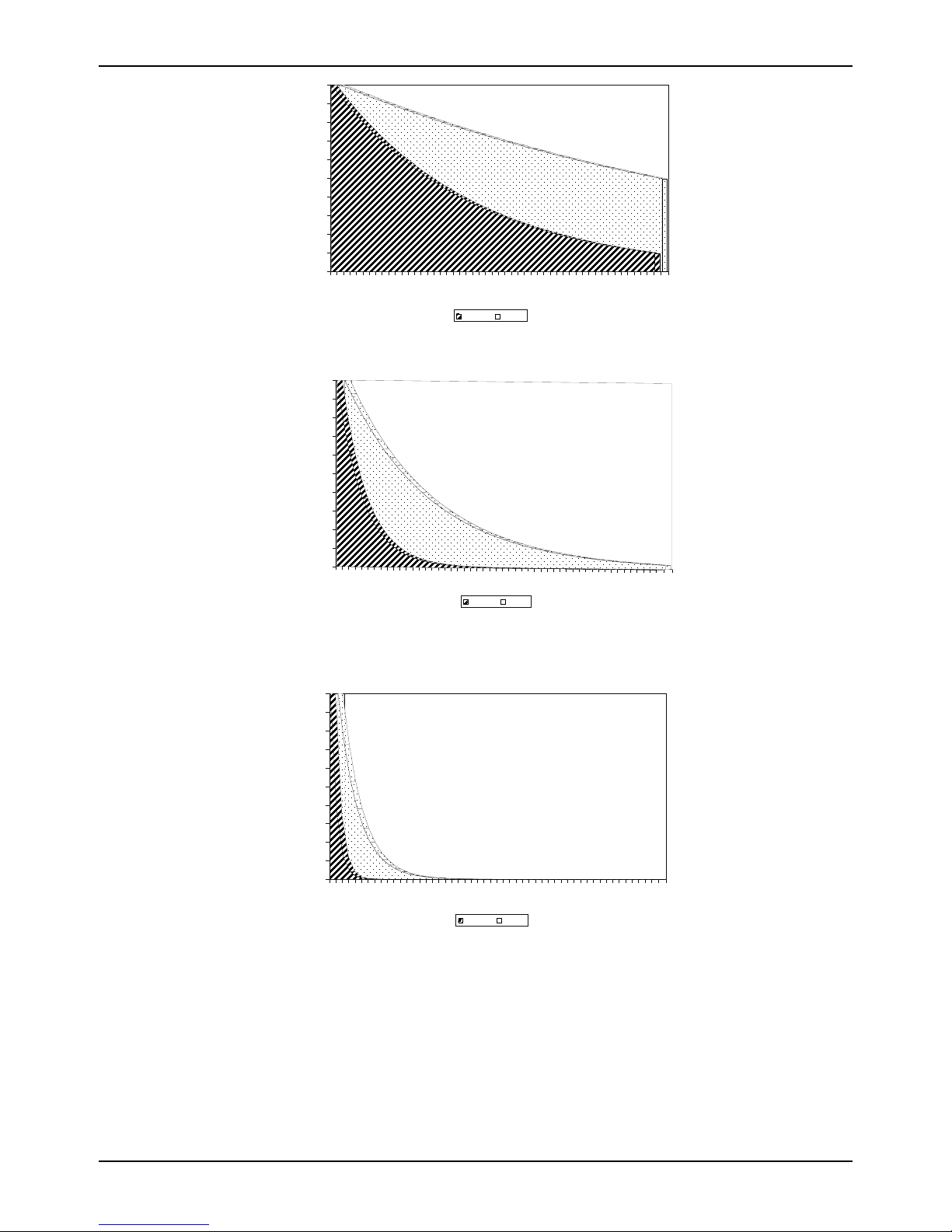
Mettler Electronics Corp.— Rev.J_09/13/17
100
90
80
70
60
50
Per Cent
40
Ultrasound Remaining
30
20
10
0
012345
Figure 7.2—Ultrasound Absorption, Fat
100
90
80
70
60
50
Percent
40
Ultrasound Remaining
30
20
10
0
0
Tissue D epth
Centimeters
3.3 MHz 1 MHz
1
2
Tissue Depth
Centimeters
3.3 MHz 1 MHz
3
4
5
Figure 7.3—Ultrasound Absorption, Muscle with the Ultrasound Beam Perpendicular to
the Muscle Fibers
100
90
80
70
60
50
Per Cent
40
Ultrasound Remaining
30
20
10
0
012345
Tissue Depth
Centimeters
3.3 MHz 1 MHz
Figure 7.4—Ultrasound Absorption, Bone
The physics of ultrasound and audible sound are similar, except for frequency. Both travel
as longitudinal waves through a conducting medium. Ultrasound waves can be
propagated in a gaseous, liquid, or solid medium, but not in a vacuum.
44
Page 45
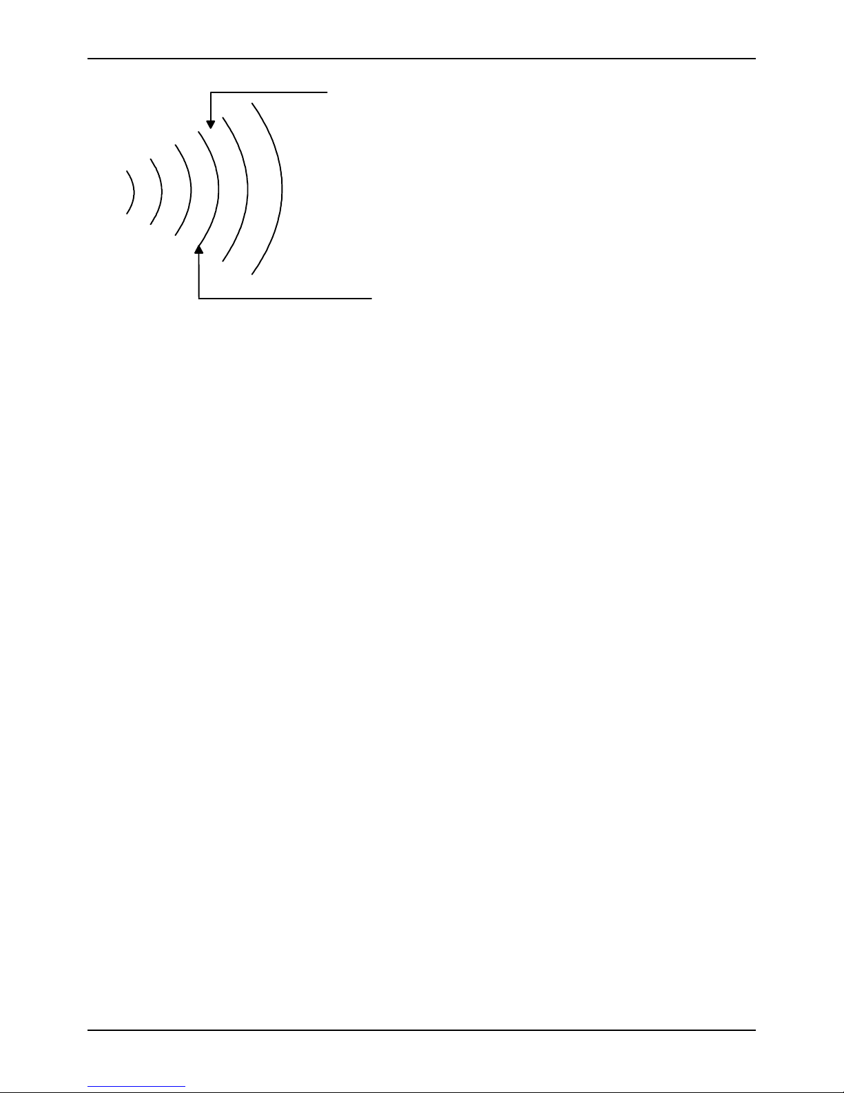
Sonicator Plus 930 Instruction Manual— Rev.J_09/13/17
Rarefaction
Areas of compression and rarefaction of the
molecules form high frequency sound waves.
Ultrasound exhibits certain beaming properties
and can be reflected, refracted, scattered or
absorbed. In passing through media, it is
attenuated and the absorbed energy is
transformed into heat. The attenuation coefficient
for longitudinal waves in liquid and soft tissues is
high, producing the phenomenon at bone surfaces
Compression
known as selective heating.
Figure 7.5—High Frequency Sound Waves
Clinical ultrasound is produced through the reverse piezoelectric effect. Electricity is
carried from a radio frequency source to an electrode in contact with the surface of a
specially cut crystal. The electrical charges applied to the crystal surface produce
mechanical vibrations, or the so-called reverse piezoelectric effect.
The crystal may be natural or synthetic and may be salt, quartz, polycrystalline or ceramic.
When this crystal is in resonance with the driving oscillator, optimum conversion from
electrical to mechanical energy is achieved. The Sonicator Plus 930 uses a barium titanate
ceramic for all of its transducers.
Ultrasonic power is expressed in watts (W), or watts per square centimeter (W/cm²).
Average intensity (W/cm²) is obtained by measuring the total output of the applicator (in
watts) and then dividing it by the size of the effective radiating area of the applicator. The
ERA (effective radiating area) is indicated on the label of each Mettler applicator. Please
note: the ERA is different from the overall dimension of the applicator face.
Ultrasound waves need a medium for their transmission and that is accomplished by
using a proper coupling agent. This coupling layer between the transducer and body
surface will assist in the propagation of the mechanical vibrations and prevent loss of
transmission.
Once the coupling agent is applied to the body surface, the applicator placed in contact
and the desired output selected in total watts, or watts per square centimeter, the
technique of application is by means of circular or stroking movement. In the circular
method, the sound head of the applicator is moved in slow and circular overlapping
movements. In the stroking, or “paintbrush” method, slow back and forth strokes are
used, again with slight overlapping. Motion with either technique should be slow enough
to insure proper energy absorption yet fast enough to eliminate excessive amounts of
absorption that could produce periosteal pain. Some references recommend that the
treatment area covered by this moving technique be two to three times the effective
radiating area of the transducer for every five minutes of exposure.
45
Page 46
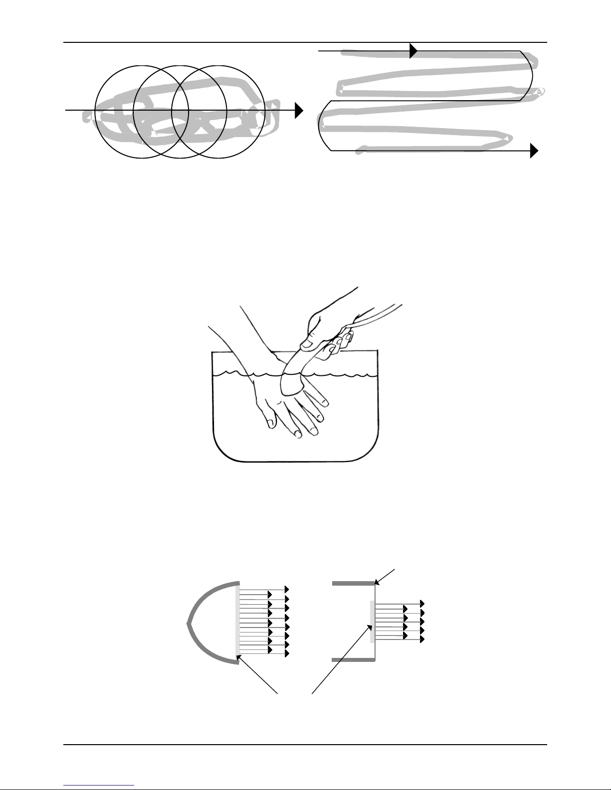
Mettler Electronics Corp.— Rev.J_09/13/17
Figure 7.6—Ultrasound Application Techniques
On occasion, irregular surfaces of the body are treated (hands) and may offer a poor
surface for proper sound head contact. The underwater technique may be used for these
applications. The part to be treated and the sound head are submerged in water and the
sound head is moved over the area, keeping the head ½ to 1 inch away from the area of
treatment. As air bubbles appear on the surface of the sound head they should be wiped
away to insure proper transmission of energy.
Figure 7.7 Underwater Treatment Technique
7.2 Output Levels
The differences between transducers of varying radiating areas are shown below. The
chart is a calculation of power output for these applicator crystals with different radiating
areas.
Metal Enclosure
Sonicator
Transducer
Disc
Figure 7.8 Differences Between Transducers
Others
46
Page 47

Sonicator Plus 930 Instruction Manual— Rev.J_09/13/17
Intensity Setting ERA Effective Power Produced
(W/cm²) (cm²) (W)
1.5 1 1.5
1.5 5 7.5
1.5 10 15.0
You will note, though the intensity setting remained constant, the amount of energy
delivered varied appreciably. We caution the user to consider this since units of different
manufacture are available in many departments. If watts per square centimeter is used as
the prescribed intensity setting, the effective watts delivered will not remain constant.
7.3 Continuous and Pulsed Waves
Ultrasound may be applied in either continuous or pulsed waveform. Advocates of pulsed
beam applications suggest the approach reduces the thermal effects while accenting the
mechanical. Wulff in his paper titled “Reduction of Thermic Effect of Ultrasound Dosages
by the Use of Pulsed Ultrasound Energy”, reported, “ .... the use of pulsed ultrasound
energy permits accurately controlled reduction of total ultrasound intensities employed in
therapy.” He recommended the use of rectangular pulses and stated, “The biologic
response reactions of the sonated tissue seems to continue during the sound free intervals
provided that a ratio between pulse duration and free interval of 1:4 is maintained.”
Laboratory research being conducted by Dyson and associates in England seems to
indicate beneficial non–thermal effects of ultrasound. However, clinical studies have not
been conducted to thoroughly corroborate this evidence.
The Sonicator Plus 930 provides both continuous and pulse wave capabilities. The
continuous mode is on more than 95% of the time and has an unmodulated wave. The
pulse setting has a pulse frequency of 100 Hz with a pulse width of 2 milliseconds and 8
milliseconds between pulses for the 20% duty cycle. In the puse mode, peak power is
displayed.
47
Page 48

Mettler Electronics Corp.— Rev.J_09/13/17
48
Page 49

Sonicator Plus 930 Instruction Manual— Rev.J_09/13/17
Section 8—References
1. Baker, L.L., Bowman, B.R., and McNeal, D.R.: “Effects of Waveform on Comfort
During Neuromuscular Electrical Stimulation”, Clinical Orthopedics and Related Research,
No. 233, pp. 75–85, August, 1988.
2. Belcher, J.: "Interferential Therapy", N.Z. Journal of Physiotherapy, 6:29-34, 1974.
3. Benton, L., et al.: Functional Electrical Stimulation – A Practical Guide, Rancho Los
Amigos Hospital, 1981.
4. Bowman, B.R. and Baker, L.L.: “Effects of Waveform Parameters on Comfort During
Transcutaneous Neuromuscular Electrical Stimulation”, Annals of Biomedical
Engineering, Vol. 13, pp. 59–74, 1985.
5. Brooks, M.E., Smith, E.M., and Currier, D.P.: “Effect of Longitudinal Versus Transverse
Electrode Placement on Torque Production by the Quadriceps Femoris Muscle during
Neuromuscular Electrical Stimulation”, JOSPT, 11:11, pp. 530–534.
6. De Dominico, G.: New Dimensions in Interferential Therapy, A Theoretical and Clinical
Guide, Reid Medical Books, Sydney, 1987.
7. De Dominico, G.: "Motor Stimulation with Interferential Currents", Australian Journal of
Physiotherapy, 31:225-230, 1985.
8. De Dominico, G.: "Pain Relief with Interferential Therapy", Australian Journal of
Physiotherapy, 28:14-18, 1982.
9. DeLitto, A. and Snyder–Mackler, L.: “Two Theories of Muscle Strength Augmentation
Using Percutaneous Electrical Stimulation”, Physical Therapy, (70:158–164), 1990
10. Dyson, M.: “Mechanisms Involved in Therapeutic Ultrasound”. Physiotherapy, March
1987, Vol. 73:3, pp. 116- 120.
11. Electrotherapy Standards Committee of the Section on Clinical Electrophysiology of the
American Physical Therapy Association. Electrotherapeutic Terminology in Physical
Therapy, APTA, 1990.
12. Ganne, J. M. "Interferential Therapy", Australian Journal of Physiotherapy, 22:101-110,
1976.
13. Hayes, K.W.: A Manual for Physical Agents, Appleton & Lange, 1993.
14. Hecox, B., Mehreteab, T.A. and Weisberg, J.: Physical Agents—A Comprehensive Text for
Physical Therapists, Appleton & Lange, 1994.
15. Kahn, J.: Principles and Practice of Electrotherapy, Churchill Livingstone, 1987.
16. Killian, C.B.: “Electrical Stimulation Overview, Introduction to High Frequency
Stimulation”, Stimulus, 1986.
17. Kottke, F.J., Stillwell, G.K. and Lehman, J.F., eds.: Krusen's Handbook of Physical
Medicine and Rehabilitation, W.B. Saunders Company, 1982.
18. Low, J. and Reed, A.: Electrotherapy Explained—Principles and practice, Butterworth–
Heinemann, 1994.
49
Page 50

Mettler Electronics Corp.— Rev.J_09/13/17
19. Jaskoviak, P.A. and Schafer, R.C.: Applied Physiotherapy – Practical Clinical Applications
with Emphasis on the Management of Pain and Related Syndromes, Associated Chiropractic
Academic Press (A.C.A.), 1986.
20. Jorgenson, S. P. "Interferential Therapy", ACA Journal of Chiropractic, 23:12, 28-30, 1986.
21. Kahn, Joseph.: Principles and Practice of Electrotherapy, Churchill Livingstone, New York,
1987.
22. Kottke, F.J.; Stillwell, G.K.; and Lehman, J.F. ed. Krusen’s Handbook of Physical Medicine
and Rehabilitation. W.B. Saunders Co., Philadelphia, 1982.
23. Mannheimer, J.S. and Lampe, G.N: Clinical Transcutaneous Electrical Nerve Stimulation,
F. A. Davis Company, 1984.
24. Michlovitz, S.L. and Wolf, S.L., ed. Thermal Agents in Rehabilitation, F.A. Davis Co.,
Philadelphia, 1990.
25. Nelson, R.M. and Currier D.P.: Clinical Electrotherapy, Appleton and Lange, 1991.
26. Nikolova, L.: Treatment with Interferential Current, Churchill Livingstone, 1987.
27. Nyborg, W.L. and Ziskin, M.C., ed. Biological Effects of Ultrasound. Vol. 16 of Clinics in
Diagnostic Ultrasound, Churchill Livingstone, New York, 1985.
28. Prentice, W.E.: Therapeutic Modalities in Sports Medicine, Times Mirror/Mosby College
Publishing, 1990.
29. Reid, D.C. and Cummings, G.C.: “Efficiency of Ultrasound Coupling Agents”.
Physiotherapy, Vol. 63:8, 1977, pp. 255- 257.
30. Savage, B. Interferential Therapy, Faber and Faber, Boston, 1984.
31. Schwann, H.P. and Carstensen, E.L.: “Advantages and Limitations of Ultrasonics in
Medicine”. JAMA 5:52 Vol. 149, 1952, pp. 121-125.
32. Selkowitz, D.M.: “Improvement in Isometric Strength of the Quadriceps Femoris
Muscle After Training with Electrical Stimulation”, Physical Therapy, (65:186–196), 1985.
33. Snyder–Mackler, L. and Robinson, A. J., eds.: Clinical Electrophysiology, Electrotherapy
and Electrophysiologic Testing, Williams and Wilkins, 1989.
34. Starkey, C.: Therapeutic Modalities for Athletic Trainers, F. A. Davis Company, 1993.
35. Wadsworth, H. and Chanmugam, A.P.P.: Electrophysical Agents in Physiotherapy –
Therapeutic and Diagnostic Use
, Science Press, Marrickville NSW 2204 Australia, 1983.
36. Warron, C.G.; Koblanski, J.N.; and Sigelmann, R.A.: “Ultrasound Coupling Media:
Their Relative Transmissivity”. Arch Phys Med Rehab, Vol. 57, 1976. pp. 218-222.
37. Wilkie, C. D. "Interferential Therapy", Physiotherapy, 55: 503-506, 1969.
38. Wolf, S.L., ed.: Electrotherapy, Churchill Livingstone, New York, 1981.
This manual has been written as a guideline for the correct use of the Sonicator Plus 930.
Reading the above references will provide a more complete understanding of the correct
use of therapeutic ultrasound, neuromuscular stimulation and combination therapy.
50
Page 51

Sonicator Plus 930 Instruction Manual— Rev.J_09/13/17
Section 9—Specifications
9.1 General Specifications:
Input: 90–240 VAC, 50–60 Hz, 2.3 Amp Nom.
Certification: The Sonicator Plus 930 complies with the ultrasound
performance standards set forth in the Code of Federal
Regulations, Title 21 (Food and Drugs), Part 1050.10
Weight: 8.7 pounds
Dimensions: 6 in (H) x 12 in (W) x 12 in (D)
Operating Temperature: +50°F to +104°F
Humidity:
Storage Temperature: -40°F to 167°F
Timer Accuracy: ±0.5 minutes for times less than 5 minutes
Maximum Treatment Time: 60 minutes–electrical stimulation
Treatment Timer: Treatment time counts down to zero when a time is set,
Operating, 30% to 75% Relative Humidity at 104F
Nonoperating, 5 to 95% Relative Humidity, noncondensing
±10% for times from 5 to 10 minutes
±1.0 minute for times greater that 10 minutes
30 minutes–ultrasound or combination therapy
or up to 60 or 30 minutes when no time is set. The
digital timer indicates time in minutes and seconds. The
timer also indicates the remaining or elapsed treatment
time during the “Hold” period.
9.2 Ultrasonic Generator Specifications:
Frequency: 1.0 MHz ±10%
3.2 MHz ±10%
Modes: Continuous
Pulse Repetition Rate: 100 Hz ±5%
Pulse Duration: 2 msec ±5%, 20% duty cycle
Temporal Peak/ average
intensity ratio:
Maximum output power: 11 W
Maximum intensity: 2.2 W/cm²
Indication accuracy: ±20% (for any level above 10% of maximum)
Output description: The output waveform is continuous or pulsed as
Pulsed—20% duty cycle
5:1 ±5%, 20% duty cycle
51
Page 52
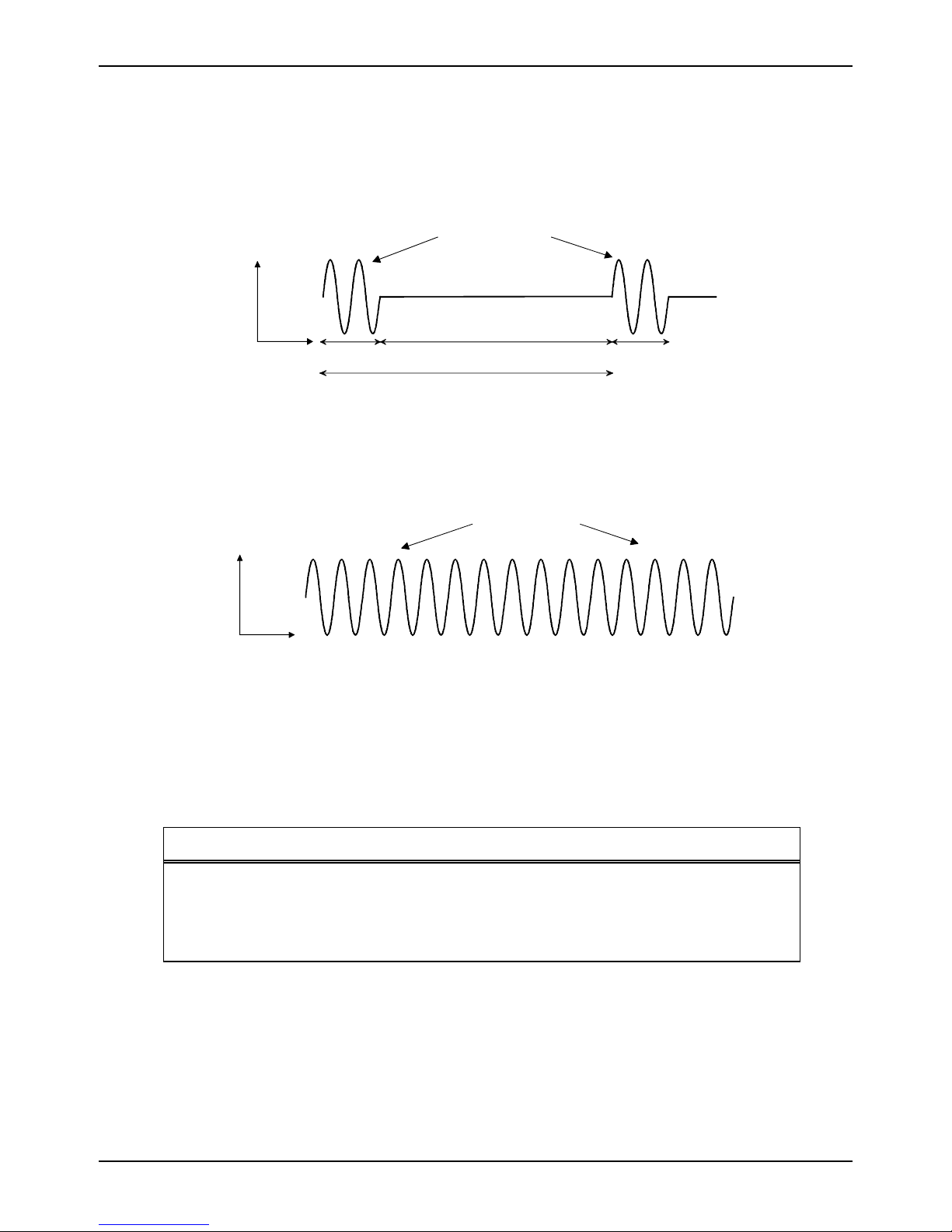
Mettler Electronics Corp.— Rev.J_09/13/17
programmed by the membrane panel control. In the
pulse mode the 1, 3.2 or 3.3 MHz sine wave pulses
are modulated. The power level is adjusted by varying
the pulse amplitude. The pulse waveforms are shown
below:
Output
1, 3.2 or 3.3 MHz
Time
2 ms 8 ms 2 ms
Pulse Space = 10 ms
Figure 9.1—Pulse Waveform—20% Duty Cycle
In the continuous mode, the power is on at least 95% of
the time the timer is running. The continuous mode
waveform is shown below:
1, 3.2 or 3.3 MHz
Output
Time
Figure 9.2—Continuous Waveform
9.3 Ultrasonic Applicator Specifications:
Piezoelectric discs: The output transducer utilizes a barium titanate disc
with a specially coated face.
Individual Applicator Specifications:
Applicator Part Number Frequency Effective Radiating Area
ME 7513 1 or 3.2 MHz ±10% 5 cm² ±20%
7310* 1 MHz ±10% 10 cm²±20%
7331* 3.3 MHz ±10% 1 cm² ±20%
The Sonicator Plus 930 must be specially calibrated to use these applicators so that they function
properly.
Maximum Beam
Non–Uniformity Ratio: 6:1
52
Page 53
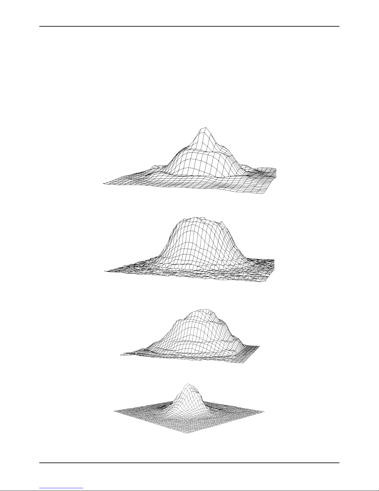
Sonicator Plus 930 Instruction Manual— Rev.J_09/13/17
Spatial Pattern: The applicator produces a collimated (cylindrical) beam
with an area of 5 cm², measured 5 mm from the ceramic
disc surface when the radiation is emitted into the
equivalent of an infinite medium of distilled water at 30° C.
The beam of the applicator is circular in all planes
parallel to the applicator face. A few inches from the
face, it is a single smooth bell-shaped curve. Nearer the
face the pattern varies more due to phase cancellations.
Sample curves measured in the far field from the surface
are shown in Figures 9.3 and 9.4.
Figure 9.3—5 cm² Applicator (1 MHz), ME 7513—Three Dimensional Beam Pattern
Figure 9.4—5 cm² Applicator (3.2 MHz), ME 7513—Three Dimensional Beam Pattern
Figure 9.5—10 cm² Applicator (1 MHz), ME 7310,—Three Dimensional Beam Pattern
Figure 9.6—1 cm² Applicator (3.3 MHz), ME 7331,—Three Dimensional Beam Pattern
53
Page 54
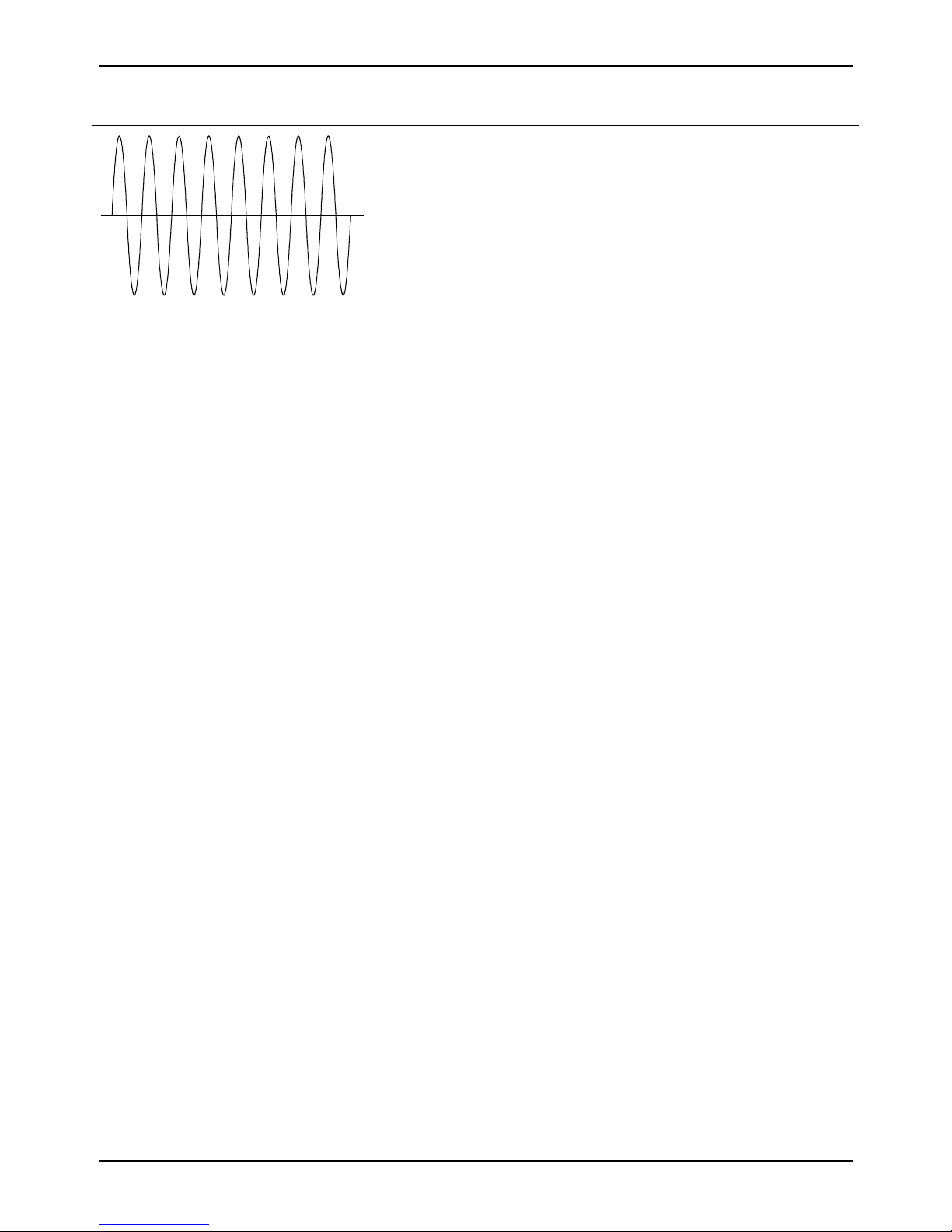
Mettler Electronics Corp.— Rev.J_09/13/17
9.4 Waveform Specifications:
Interferential Mode
Waveform Type: Sinewave
Polarity: None
Volts: 0–65 volts RMS, 1 Kohm load
Current: 0–65 mA RMS, 1 Kohm load
Average current at
maximum intensity
and frequency: 65 mA RMS
Figure 9.7—Interferential
Waveform
Maximum current
density under 2"
diameter electrode. 3.2 mA/cm²
Frequency: Channel 1 = 4000 Hz
Frequency Modulation: 1–15 Hz
80–150 Hz
1–150 Hz
xx–xx Hz,
xx=any value from
1 to 250 Hz
Channel 2 = 4000 to 4250
Hz variable frequency sine
wave
Phase Duration: 125 s
Available Amplitude
Modulation Options: Vector rotation
Available Channels: Channels 1 & 2
54
Page 55

Premodulated Mode
Figure 9.8—Premodulated
Waveform
Sonicator Plus 930 Instruction Manual— Rev.J_09/13/17
Waveform Type: Amplitude modulated
sine wave
Polarity: None
Volts: 0–50 volts RMS, 1 Kohm load
Current: 0–50 mA RMS,
1 Kohm load
Average current at
maximum intensity
and frequency: 50 mA RMS
Maximum current
density under 2"
diameter electrode. 2.5 mA/cm²
Frequency: 4,000 Hz
Frequency Modulation: 1–15 Hz
80–150 Hz
1–150 Hz
xx–xx Hx,
xx=any value from
1 to 250 Hz
Phase Duration: 125 s internal sine wave
4–1,000 ms beat envelope
Available Amplitude
Modulation Options: Continuous
Surge
Reciprocation
Available Channels: All
55
Page 56
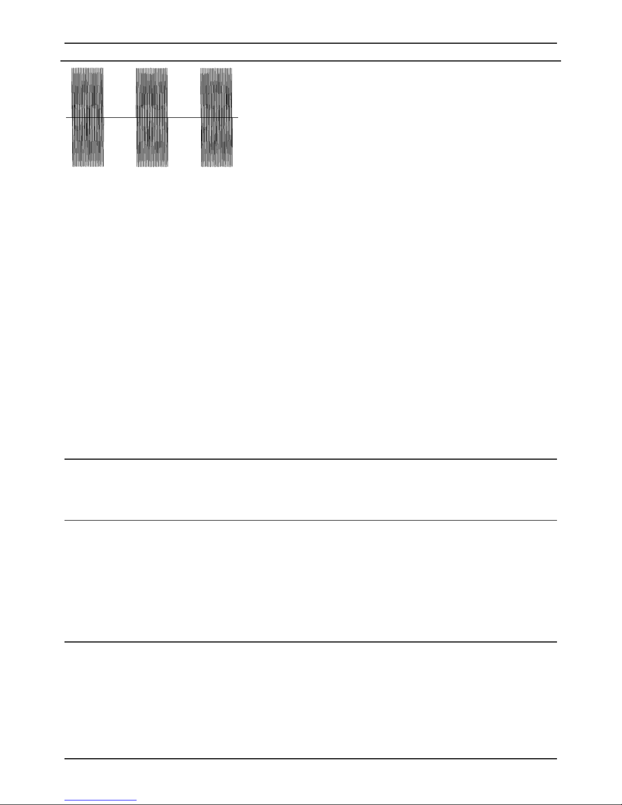
Mettler Electronics Corp.— Rev.J_09/13/17
Medium Frequency Mode
Waveform Type: Burst modulated sine wave
Polarity: None
Volts: 0–50 volts RMS, 1 Kohm load
Current: 0–50 mA RMS, 1 Kohm load
Average current at
maximum intensity
and frequency: 50 mA RMS
Figure 9.9—Medium Frequency
(Russian) Waveform
Maximum current
density under 2"
diameter electrode. 2.5 mA/cm²
Frequency: 2500 Hz, Burst at
10 ms on and 10 ms off
Frequency Modulation: No
Phase Duration: 200 s
Available Amplitude
Modulation Options: Continuous
Surge
Reciprocation
Available Channels: All
9.5 Amplitude Modulation Specifications:
Vector rotation: Interferential Mode Only,
-50% amplitude modulation in
anti phase with an eight second modulation period.
Surge Mode: Premodulated and Medium Frequency
Up ramp: 3 seconds
Down ramp: 2 seconds
Preset on/off times: 5 seconds on, 5 seconds off
10 seconds on, 10 seconds off
10 seconds on, 30 seconds off
10 seconds on, 50 seconds off
Reciprocation mode: Premodulated and Medium Frequency
Up and down ramps: 1 second, reciprocation only
Reciprocation time: 2–240 seconds, (On time = off time)
56
Page 57

Sonicator Plus 930 Instruction Manual— Rev.J_09/13/17
Section 10—Accessories
10.1 Ordering Information:
Therapy products and accessories are available from Mettler Electronics authorized
Distributors. For information regarding either Mettler products or a distributor near you,
please call toll free, (800) 854–9305 or phone (714) 533–2221 in areas outside the continental
United States. Ask for Customer Service. Mettler Electronics is open from 7 AM until 5 PM
Pacific Time for your convenience. You can also reach our Customer Service Department
via email at [email protected].
10.2 Sonicator Plus 930 Accessories
Catalogue # Item Description
1844 Sonigel—salt free clear gel couplant, case of 12, 9.5 oz. tubes
1852 Sonigel clear gel couplant, (1 x 5 liters)
1853 Sonigel clear gel couplant, (4 X 5 liters)
1863 Sonigel Lotion with Aloe Vera, 1 gallon with pump and pour off bottle
1864 Sonigel Lotion with Aloe Vera, 4 X 1 gallon individually packaged
2000 4 Sponge electrodes (2" x 2")
2001 24 Sponge inserts (2" x 2")
2002 4 Sponge electrodes (4" x 4")
2003 24 Sponge inserts (4" x 4")
2004 1 Sponge electrode (3.5" x 7")
2005 12 Sponge inserts (3.5" x 7")
2006 1 Sponge electrode (8" x 10")
2007 12 Sponge inserts (8" x 10")
2008 4 Electrode straps (24")
2009 4 Electrode straps (48")
2030 Bifurcated cord set, one red and one black, , pin termination
2023 Pencil electrode set with push button stimulation control, (includes handle,
4 different sizes of stainless steel spot electrode tips, and carrying case)
2027 Pin to banana adapter plug set to be used with ME 2260 or 2201 electrode
cables. Four each, gray.
2230 Bifurcation cable set, 2 cables, one red and one black, pin termination
2221 EZ Trode – 2" diameter round self–adhering, reusable electrodes with
lead wires; case of ten packages (four electrodes/pkg.)
2222 EZ Trode – 3" diameter round self–adhering, reusable electrodes with
lead wires; case of ten packages (four electrodes/pkg.)
57
Page 58

Mettler Electronics Corp.— Rev.J_09/13/17
2223 EZ Trode – 2" x 5" self–adhering, reusable electrodes with lead wires,
case of 10 packages (2 electrodes/pkg.)
2224 EZ Trode – 2" square self–adhering, reusable electrodes with lead wires;
case of ten packages (four electrodes/pkg.)
2260 Electrode cable for the Sonicator Plus 930 with pins
2261 Single cord electrode cable for the Sonicator Plus 930 for combination
therapy
2702 V Trode –2" diameter round electrodes with lead wires, case of ten
packages (four electrodes/pkg.)
2703 V Trode –2.75" diameter round electrodes with lead wires, case of 10
packages (four electrodes/pkg.)
2704 V Trode –2" x 4" oval electrodes with lead wires, case of 10 packages
(four electrodes/pkg.)
2705 V Trode –2" square electrodes with lead wires, case of 10 packages (four
electrodes/pkg.)
7293 Detachable U.L. listed, hospital–grade line cord
7310 Sonicator 716, 730, 930. 992 and 994 applicator (10 cm²/ 1 MHz), Please
submit Sonicator Plus 930 to be calibrated to use this applicator so that the 7310
applicator functions properly.
7331 Sonicator 730, 930. 992 and 994 pencil style applicator (1 cm²/ 3.3 MHz)
Please submit Sonicator Plus 930 to be calibrated to use this applicator so that
the 7331 applicator functions properly.
73 Three-shelf mobile cart for all Sonicator Plus products. Holds unit on the
top shelf with lower shelves for accessories.
7392 Hooded, water-proof universal applicator cable for the Sonicator Plus
930, 992 and 994
7513 Sonicator Plus 930, 992 and 994 applicator (5 cm²/ 1 or 3.2 MHz)
9901 Electrical Stimulation & Ultrasound Pocket Guide II by Michelle H.
Cameron. Designed for use with the Sonicator Plus 930.
58
 Loading...