


T
2-Channel Electrotherapy/Ultrasound Combo
Sonicator® Plus 921
OPERATION MANUAL
1333 South Claudina Street • Anaheim, CA 92805, U. S. A.
Toll Free: (800) 854–9305 • Telephone: (714) 533–2221 • FAX: (714) 635–7539
Web Site: http://www.mettlerelectronics.com • Email: mail@mettlerelectronics.com
IR8–46 Rev. B_10/11/18
oensurecorrectuse,pleasereadthismanualcarefully
beforeoperatingtheunit.Afterreading,storetheman-
ualinasafeplaceforfuturereference.

contents
Symbols ···································································································· 1
To Ensure Correct and Safe Use
Intended use ···························································································· 2
Contraindications ······················································································ 2
Precautions ····························································································· 4
Storage condition ······················································································ 7
Precautions on Handling ············································································· 7
Maintenance and Inspection ········································································ 7
Device Configuration ··················································································· 9
Specifications ··························································································· 11
Names of Parts ························································································· 12
Preparations for Electrotherapy ···································································· 14
Display of Electrotherapy Screen ·································································· 24
Operation for Electrotherapy ······································································· 26
Setting Parameters for 4-Pole Interferential Mode ············································ 29
Setting Parameters for 2-Pole Interferential Mode ············································ 32
Setting Parameters for EMS Mode ······························································· 35
Setting Parameters for Russian Mode ··························································· 38
Setting Parameters for Hi-Voltage Mode ························································ 41
Setting Parameters for TENS Mode ······························································ 44
Setting Parameters for Microcurrent Mode ····················································· 48
Setting Parameters for Galvanic Mode ·························································· 51
Preparing for Ultrasound Therapy ································································· 74
Ultrasound Therapy Screen ········································································· 76
Operation for Ultrasound Therapy ································································· 78
Preparing for Combination Therapy ······························································ 82
Combination Therapy Screen ······································································ 84
Operation for Combination Therapy ······························································ 86
Display of Clinical Program Screen ······························································· 90
Operation of Clinical Program ······································································ 92
Saving Programs ······················································································ 94
Loading Programs ····················································································· 96
Setting Screen·························································································· 98
Error Screen ·························································································· 101
EMC····································································································· 102

Symbols & Abbreviations
Symbol for “CAUTION”
Symbol for “CONSULT
INSTRUCTIONS FOR
USE”
Symbol for “ELECTROSTATIC
SENSITIVE DEVICES
Symbol for “POWER ON” (Power
switch)
Symbol for
“TEMPERATURE LIMIT”
Symbol for
“HUMIDITY
LIMITATION”
Symbol for
“ATMOSPHERIC
PRESSURE
LIMITATION”
Symbol for “AC (alternating current)”
Symbol for “TYPE BF APPLIED
PART”
Symbol for “NON-IONIZING
ELECTROMAGNETIC RADIATION”
Symbol for “POWER OFF” (Power
switch)
Symbol for “PAUSE” (Pause switch)
Symbol for “STOP” (Stop switch)
Symbol for “US applicator output port”
Symbol for cTUVus certification
Symbol for prescription only
List of Abbreviations
cm² — Square centimeters
Hz — Hertz (pulses per second)
LCD — Liquid crystal display
LED — Light Emitting Diode
MHz — Megahertz (1 x 10
s — Microsecond (1 x 10
mA — Milliampere (1 x 10
ms — Millisecond (1 x 10
min — Minutes
sec — Seconds
S/N — Serial Number
W — Watts
W/cm² — Watts per square centimeter
6
cycles per second)
-6
second)
-3
ampere)
-3
second)

Federal law restricts the sale of this device to, or on the order of a physician, dentist, veterinarian or
any other practitioner licensed by law of the state in which he practices.
Use of controls or adjustments or performance of procedures other than those specified herein may
result in hazardous exposure to ultrasonic energy. Treatment should be administered only under
the direct supervision of a health care professional.
The electric energy delivered by this device may possibly be lethal. Treatment should be
administered only under the direct supervision of a health care professional. The stimulus delivered
by this device may be sufficient to cause electrocution. Electrical current above 25 µC must not flow
through the thorax because it may cause a cardiac arrhythmia.
Intended use
Indications for electrotherapy
Intended use for Interferential (IF-4), Interferential (IF-2), TENS, Microcurrent, Galvanic
1. Symptomatic relief of chronic intractable pain
2. Post-traumatic pain
3. Post-surgical pain
Indications for EMS, Russian, Hi-Voltage and TENS modes
1. Relaxation of muscle spasms
2. Increase local blood circulation
3. Prevention or retardation of disuse atrophy
4. Muscle re-education
5. Maintaining or increasing range of motion
6. Immediate post-surgical stimulation of calf muscles to prevent venous thrombosis
Indications for DC (Direct Current) waveform
1. Relaxation of muscle spasm
Indications for therapeutic ultrasound
1. Relief of pain, muscle spasms and joint contractures:
2. Relief of pain, muscle spasms and joint contractures that may be associated with:
● Adhesive capsulitis
● Bursitis with slight calcification
● Myositis
● Soft tissue injuries
● Shortened tendons due to past injuries and scar tissues
3. Relief of pain, muscle spasms and joint contractures resulting from:
● Capsular tightness
● Capsular tightening

Contraindications
Contraindications for Neuromuscular Electrical Stimulation
1) Anterior neck of the carotid sinus region
2) Electrical neuromuscular stimulation should not be administered to individuals who
are or may be pregnant.
3) Do not stimulate a patient who has a cardiac demand pacemaker.
4) Patients with implanted electronic devices should not be subjected to stimulation.
5) Placement of electrodes across the chest laterally or ante¬rior/posterior creates a
possible hazard with cardiac patients and is therefore not recommended. Do not use
transthoracically in any mode. Great care should be exercised in applying the
electrical stimulus current to any region of the thorax because the stimulus current
may produce cardiac arrhythmia. In patients with known heart disease, electrical
stimulation should be used only after careful physician evaluation and patient
instruction.
6) Place electrodes in such a way to avoid stimulation of the carotid sinus (neck)
region.
7) Patients with arterial or venous thrombosis or thrombophlebitis are at risk of
developing embolisms when electrical stimulation is applied over or adjacent to the
vessels containing the thrombus. If a patient has a history of deep vein thrombosis,
even many years past, the affected area should not be stimulated.
8) Do not use over swollen, infected, or inflamed areas. Do not place electrodes over
skin eruptions.
9) Fresh fractures should not be stimulated in order to avoid unwanted motion.
10) Do not apply stimulation transcerebrally (through the head).
11) Do not use on cancer patients.
12) Stimulation should not be applied immediately following trauma or to tissues
susceptible to hemorrhage.
13) Positioning electrodes over the neck or mouth may cause severe spasm of the
laryngeal or pharyngeal muscles. These contractions may be strong enough to close
the airway or cause difficulty in breathing.
14) Do not apply stimulation for undiagnosed pain syndromes, until etiology is
established.
15) Do not apply electrodes directly over the eyes or inside body cavities.
16) Do not use electrical stimulation in conjunction with high frequency surgical
equipment or microwave or shortwave therapy systems.
Contraindications for therapeutic ultrasound
1) Therapeutic ultrasound should not be applied over the pregnant or potentially
pregnant uterus. Therefore, therapeutic ultrasound should not be applied over the
uterus unless specific assurance can be attained from the patient that she is not
pregnant.
2) Patients who have cardiac pacemakers should be protected from direct ultrasound
exposure over the thorax to protect the lead wires and pacer from such exposure.
3) Therapeutic ultrasound should not be applied to the eye.

4) Applications of therapeutic intensities of ultrasound should be avoided over the heart.
5) Neoplastic tissues or space occupying lesions should not be exposed to ultrasound.
6) Ultrasound should not be applied to the testes to avoid increases in temperature.
7) Areas of thrombophlebitis should not be treated with therapeutic ultrasound due to the
increased possibility of clotting or dislodging a thrombus. Conditions where this might
occur are deep vein thrombosis, emboli and severe atherosclerosis.
8) Tissues previously treated by deep x–ray or other radiation should not be exposed to
therapeutic ultrasound.
9) Ultrasonic treatment over the stellate ganglion, the spinal cord after laminectomy,
subcutaneous major nerves and the cranium should be avoided.
10) Do not treat ischemic tissues in individuals with vascular disease where the blood
supply would be unable to follow the increase in metabolic demand and tissue
necrosis might result.
11) Do not apply therapeutic ultrasound over a healing fracture.
12) Ultrasound should not be applied over the epiphyseal areas (bone growth centers)
of the bones of growing children.
Contraindications for combination therapy of therapeutic ultrasound and electrotherapy
1) Contraindication for combination therapy refers to the contraindications under
therapeutic ultrasound and electrotherapy
Warnings
Warnings for Neuromuscular Electrical Stimulation
1) Electrical stimulation is ineffective for pain of central origin.
2. Electrical stimulation must be applied by a physician or other qualified practitioner and
should be used for only the prescribed purposes.
3. Electrical stimulation is of no curative value.
4. Electrical stimulation is a symptomatic treatment and as such suppresses the
sensation of pain, which could serve as a protective mechanism.
5. The safety of electrical stimulators for use on children has not been determined. Keep
out of reach of children.
6. Electronic monitoring equipment (such as ECG monitors and ECG alarms) may not
operate properly when electrical stimulation is in use.

Precautions
Precautions for Neuromuscular Electrical Stimulation
1) Care should be taken in the treatment of patients receiving another type of electrotherapeutic
treatment (such as conventional TENS) or having indwelling electrodes, lead wires, or
transmitters (for electrophrenic pacing or cerebellar or urinary bladder stimulation). Stimulation
currents should not cross the lead wires or electrodes.
2) It is advisable to insulate patients, preferably by use of a wooden treatment table or one that is
completely padded by non–conductive material. Added safety is provided if the patient cannot
touch any grounded metal parts.
3) Limit treatment intensity to 50 mA (50 V) or less, when using small electrodes (2" diameter), to
reduce the chance of thermal burns due to high current density. Avoid current densities
exceeding 2 mA/cm² when using this device.
4) Isolated cases of skin irritation may occur at the site of electrode placement following long–
term application.
5) Avoid placing electrodes directly over open wounds since current density tends to concentrate
in these areas.
6) Use extreme caution when treating desensitized areas or on patients who may not be able to
report discomfort or pain.
7) Use caution in applying electrical stimulation over areas where there is a loss of normal skin
sensation.
8) Adequate precautions should be taken in the case of persons with suspected or diagnosed
epilepsy.
9) Patients should not be left unattended during any treatment.
10) Care should be taken following recent surgical procedures when muscle contraction may
disrupt the healing process.
11) Do not apply electrical stimulation over the menstruating uterus.
12) The long–term effects of chronic electrical stimulation are unknown.
13) Electrode placement and stimulation settings should be based on the guidance of the
prescribing practitioner.
14) Effectiveness for pain management is highly dependent upon patient selection by a person
qualified in the management of pain patients.
15) The Sonicator Plus 921 should be used only with electrode cables and electrodes
recommended for use by Mettler Electronics Corp.
16) Turn on the Sonicator Plus 921 before applying electrodes to the patient.
Precautions for Therapeutic Ultrasound
1) Ultrasound should not be applied in areas of reduced sensation or circulation. Patients having
reduced sensation will not be able to notify the practitioner of discomfort if ultrasound intensities are
too high. Patients with compromised circulation may have an excessive heat buildup in the
treatment area.
2) Operators should not routinely expose themselves to therapeutic ultrasound. The applicator
handles for the Sonicator Plus 921 have been designed to allow the practitioner to perform

General precautions
1) Do not operate this device near high frequency devices such as shortwave or microwave
therapeutic devices. For example, distance of more than 1.5 m is recommended.
2) Do not use this device if the patient is connected to a high-frequency surgical instrument as this
could cause skin irritations or burns and possible damage to the device.
3) Electronic monitoring equipment (such as ECG monitors and ECG alarms) may not operate
properly when stimulation of this device is in use.
4) When using this device for the purpose of Symptomatic relief of pain, the etiology of the pain should
be established or the pain syndrome should be diagnosed.
5) Make sure the patient is free of contagious disease or conditions, since these can be transmitted
to other individuals via the device or accessories.

6) Over the uterus during menstruation
7) Treatment over bony areas may cause irritation.
8) Areas with implanted metals near the skin surface.
9) Determining treatment intensity can be problematic with babies or infants (aged 6 or under),
patients with senile dementia, or other patients who for any other reason are unable to express
their preferences. Proceed carefully before deciding whether to use this device on such patients.
10) Have the patient remain in a relaxed and comfortable position during treatment.
11) Accessories from other devices should not be used with this device
12) Note the power supply frequency, voltage, and allowable current (or power consumption).
13) Use an outlet set aside exclusively for this device.
14) To avoid the risk of electric shock, this device must only be connected to a supply mains with
protective earth.
15) Do not paste the self-adhesive electrode (adhesive pad) to the coated surface of the product.
The product may be stained or its coating may be damaged.
16) Before initiating therapy with this device, check for any short circuiting of the attached electrodes
(probe). Do not place the electrodes (probe) too close to each other or else they may short
circuit. If the output is activated with short-circuited electrodes (probe), the output may be
delivered abruptly as soon as the short circuiting is cleared. Meanwhile if adjacent channels
are used in the same electrotherapy mode, do not bring the electrodes (probe) too close to
each other. Such proximity could cause overlapping outputs, depending on the mode in use,
resulting in excessively intense stimulation.
17) When using this device keep a distance where the device is reachable.
Precautions before use
1) Carefully review the patient’s diagnosis and prescription for special precautions or instructions.
①Make sure pacemakers or other medical devices are not implanted in the treatment area.
②For areas in which skin sensation is reduced, carefully consider the relevant factors before
determining whether to use this system with the patient.
2) Have the patient inform the operator, incase of experiencing unusual sensations (e.g., pain, heat
sensations, or pressure) during treatment.
3) Carefully weigh all pertinent factors before determining to use this device with the following
individuals or on the following areas:
①Carefully select the output level and treatment durations when treating facial areas.
②Do not place the electrode on the chest; doing so will increase the risk of cardiac fibrillation.*
③When using the device on a child according to a physician’s prescription, take great care when
treating bony regions that no irritations occur.*
4) Check the switches and keys to determine that the device is operating properly.
5) Make sure all cables are correctly connected and safely configured.
6) Make sure that the ultrasound probe is clean and free of any cracks.*
2
2
1

Precautions during use
1) Make sure the treatment duration and intensity are suitable for the treatment purpose.
2) Monitor the device and the patient to ensure that no problems arise. In the event of any
trouble, take appropriate measures, safely shut down the device and contact the distributor or
Mettler Electronics.
3) To prevent accidents, make sure the patient does not operate or touch the device.
4) When using the strap for electrotherapy, make sure the strap will not be in contact with bare
skin for many hours. The strap may cause allergic symptoms, such as itching, redness, hives,
swelling, fever, breathing difficulties, asthma-like symptoms, drop in blood pressure, and shock.
Should such symptoms appear, immediately halt operations and take adequate measures.
5) If the patient reports abnormal pain or heat sensation, halt treatment and see if the pain goes
away. A problem may have occurred, or heat may have built up in the patient’s body, in which
case burns may result if treatment is continued, even at a reduced output.
6) If a rash, redness, itching or any other symptoms emerge, halt use immediately and take
adequate measures.
7) Only touch one point on the touch panel at a time; do not touch multiple points simultaneously.
8) If the patient complains of periosteal pain, reduce the intensity.*
2
9) Make sure the ultrasound probe is positioned correctly on the treatment area. Incorrect positioning
can affect effectiveness and results.*
2
10) Do not leave the device with the output turned on. Buildup of heat may damage the device.*
2
11) When the ultrasound probe is not in use, return and set the probe on the probe holder.*
12) Please be careful not to put excessive pressure between the electrode and the treatment area
while the device is outputting. Please avoid actions such as putting pressure on the electrode
between the treatment area and the bed or the back of the chair during treatment lying down
or sitting. Those actions may cause an accident.*
1
Precautions after use
2
1) After using this device, go through the specified steps, turn off the power and disconnect the
power supply cord from the outlet.
2) When disconnecting the power supply cord from the outlet, make sure the power switch is off.
Always grasp the cable by the plug when connecting or disconnecting.
2
3) Rinse the ultrasound probe with lukewarm water lightly and thoroughly wipe it dry.*
4) Keep the device and accessories clean to avoid inconvenience for the next therapy session and
store them in a safe place.
*1: Precautions relating to electrotherapy
*2: Precautions relating to ultrasound
Unmarked precautions apply to all modes.

Storage conditions
1) To avoid malfunctions, follow the instructions given below when storing and installing the device.
①Avoid locations where the device will be subjected to water. Water entering the device may
cause malfunction.
②Avoid locations where the system may be unduly affected by atmospheric pressure,
temperature, humidity, sunlight, dust, salt, sulfur or any other adverse factors.
③Make sure the device is kept on a stable surface. Avoid tilting the device, or applying vibrations
and shock (these warnings also apply during transportation).
④Avoid flammable atmospheres, such as flammable anesthetic gas mixed with oxygen, nitrous
oxide and air, and flammable disinfectant or cleanser mixed with air.
⑤Avoid locations where chemicals are stored or where gas may be generated.
⑥Do not install the device near a flame. Doing so may result in deformation or accidents.
Precautions on Handling
1) Do not operate the main unit with wet hands.
2) Do not subject the product to strong vibrations or impact, whether by knocking it against another
object, tipping it over, or dropping it. Even if the product appears to function normally after
being exposed to impact or vibration, internal damage may gradually progress and result in
equipment malfunctions or accidents.
3) When disposing of consumable parts, residual materials, or end-of-life equipment/accessories,
observe all applicable local laws and regulations in the area where the equipment is installed
to minimize environmental effects.
Maintenance and Inspection
Precautions
1) In the event of product malfunction or failure, do not attempt to correct the problem. Contact the
Mettler Electronics or distributor.
2) Do not modify the product. 3
)Do not open the product case.
4) Do not clean the main unit or accessories by wiping with volatile oils (such as thinner, gasoline,
and kerosene), polishing powder, hot water, or chemicals. Such materials can discolor or
degrade the product. To clean, soak a cloth with alcohol, cold water, lukewarm water, or neutral
detergent, wring thoroughly, then wipe.
5) The probe head features a waterproof structure. Do not remove the probe head. Removing
the head may degrade waterproofing performance and oscillator performance and lead to
equipment malfunctions.

To Ensure Correct and Safe Use
Maintenance and inspection by the user
1) Inspect the product and accessories routinely before use to ensure proper functioning.
2) If any abnormalities are found (insulation damage in accessories, scratches/cracking on cord
sheaths, almost disconnected wires, faulty connector contacts, etc.) during pre-operation
checks or inspections, contact the dealer or the Mettler Electronics.
3) When using the product after an extended period without use, make sure the product functions
normally and safely before use.
Maintenance and inspection by a contractor
1) Ask the distributor or Mettler Electronics for periodic inspections (about once a year) to
maintain equipment performance and ensure safety.
2.) To assure compliance with FDA, 21 CFR 1050.10 ultrasound standard, the ultrasound
portion of the Sonicator Plus 941 should be calibrated and safety tested on an annual basis.
This service may be obtained from the manufacturer by sending the Sonicator Plus 941 in its
original shipping container to Mettler Electronics Corp., 1333 South Claudina Street,
Anaheim, CA 92805, ATTN: Service Department. (Telephone toll free: (800) 854–9305,
Alternate telephone number: 1 (714) 533–2221) This service may also be performed by
qualified biomedical engineers or technicians trained in ultrasound calibration.
3) Replace consumable parts (including accessories) periodically to prevent hazardous situations
resulting from use of equipment/accessories in improper condition.
Maintenance and inspection items
Item Description Method
Exterior and
display
Operation
Accessories
Safety
inspection
Ultrasound
output check
Check the exterior for damage. Check the LCD panel to make
sure there is no deformation or flickering of the display.
·
Turn on the power switch and confirm that the product functions
normally, without problems.
·
Confirm that the product functions normally as described in the
operation manual.
·
Check the accessories for damage.
·
Confirm that there are no wire breaks in the cords or cables.
·
While the product is producing low frequency output, disconnect
the electrode cable from the output port. Confirm that an error
indication appears and that the output stops.
·
Connect and disconnect the ultrasound probe from the product
during treatment. Confirm that an error indication appears and
that the output stops.
·
Set the ultrasound output level and allow the product to stand at
least three minutes without operating it. Confirm that the output
stops automatically.
Place water on the probe head and turn output on. Check to
make sure that the water vibrates.
Visual inspection
Operational
inspection
Visual inspection
Operational
inspection
Operational
inspection

probe check
Ultrasound
Make sure that the head section has no cracks and that the cable
connecting areas have no flaws that may allow water, ultrasound
gel, or other materials to enter the probe head.
Check the cable and connector for faulty connections.
Visual and
operational
inspections
Operational
inspection

Device Configuration
●Main unit and standard accessories
①
Your new Sonicator Plus 921 comes complete with all the necessary components to perform
therapeutic ultrasound, neuromuscular electrical stimulation and combination therapy. Below is a list of
items that are included in the shipping carton.
1. Sonicator Plus 921
2. Large ultrasound applicator, ~5.5 cm² at 1 and 3 MHz, (ME 9411)
3. Sonigel, ultrasound couplant gel, one sample tube, 100 ml, (ME 1846)
4. Two electrode cable sets, (ME 2266)
5. One package V Trodes, 2" diameter (ME 2702))
6. Two 4"x 4" sponge electrodes, (ME2002)
7. Two pin to banana adapters, (ME 2027)
8. Detachable U.L. listed, hospital–grade line cord
9. Instruction Manual on a CD ROM
●Optional accessories
1. Small applicator (9412)
2. Sponge Electrode 2x2 (2000)
3. Sponge Electrode 4x4 (2002)
4. Sponge Electrode 3.5 x 7 (2004)
5. Sponge Electrode 8 x 10 (2006)
6. Banana Jack (2027)
7. Electrode straps 24 " (2008)
8. Electrode straps 48 " (2009)
9. Vtrode (2703)
10. Vtrode (2704)
11. Vtrode (2705)
12. EZ Trode Electrode (2221)
13. EZ Trode Electrode (2222)
14. EZ Trode Electrode (2223)
15. EZ Trode Electrode (2224)
16. High Voltage Probe (2267

Specifications
●Main unit specifications
Power supply 120 V 60 Hz
Power consumption 140 VA
Electrotherapy
Output current
Output voltage
Output frequency Max. 10 kHz ±10%
Timer Max. 60 min. ±5%
Ultrasound frequency 1.0 MHz, 3.0 MHz ±10%
Intensity
Pulse frequency 16 Hz, 48 Hz, 100 Hz ±5%
Output mode Duty 5%, 10%, 20%, 30%, 40%, 50%, 100% ±5%
Timer Max. 30 min. ±5%
Ultrasoun
Oscillator
ERA
BNR
Output stability ±20%
Applicator maximum
temperature
Certification
Safety class according to
IEC 60601-1
Class of protection against
ingress of harmful water
Dimensions 13.8" (W) x 10.6" (D) x 5.7" (H)
Weight Approx. 7.7 lb.
Environmental
conditions
Max. 600 mA ±15% peak (500 Ω load), Max. 70 mA rms ±15% (500 Ω load)
Max. 300 V ±15% peak (500 Ω load)
Limit value and accuracy: 3.0 W/cm2 ±20%
Maximum effective intensity: 2.0 W/cm
Peak intensity: 3.0 W/cm2 ±20% (pulsed)
Ultrasound Probe (L) 1 MHz: 5.5 cm
Ultrasound Probe (S) 1 MHz: 0.9 cm2 ±20%
Ultrasound Probe (L) 1 MHz: 4.6 ±30%
3 MHz: 2.9 ±30%
Ultrasound Probe (S) 1 MHz: 2.9 ±30%
3 MHz; 6.0 cm
3 MHz: 0.9 cm
3 MHz: 2.9 ±30%
43°C
The Sonicator Plus 921 complies with the ultrasound performance standards
set forth in the Code of Federal Regulations, Title 21 (Food and Drugs), Part
1050.10.
Class I, Type BF
Main unit: IPX 0
Ultrasound probe: IPX 7
Temperature Humidity Pressure
In use 10−40°C 30−75% 800−1060 hPa
Storage -10−60°C 30−95% 700−1060 hPa
Transportation -10−60°C 30−95% 700−1060 hPa
cTUVus ME 921
2
±20% (continuous)
2
±20%
2
±20%
2
±20%

Names of Parts
● Main Unit
①
②
③ ④
①LCD touch panel ②Stop switch
③Current intensity control dial (CH1) ④Current intensity control dial (CH2)
⑤Ultrasound intensity control dial (US)
⑥ ⑦
⑥Electrode cable connection port (CH1) ⑦Electrode cable connection port (CH2)
⑧
⑤
⑨
⑧LED ⑨Ultrasound Probe connection port
⑪
⑫
⑪
11 Power switch
12 Power supply cord connection port

1
Make sure the power switch for the Main Unit is
turned off.
2
Connect the power supply cord to the power supply
cord connection port on the Main Unit.
3
Connect the power supply cord to an AC power
outlet.
4
Select the electrode suitable for the treatment to be
performed and the treatment area, then connect
the electrode cable to the electrode cable
connection port on the Main Unit.
● The Rubber Electrode and Self-adhesive Electrode
(optional) can be used in any treatment mode.
● The HV/DC Probe can be used only in Hi-Voltage
and Galvanic modes.
* For information on using each electrode, see pages 15 to 23.
5
Turn on the power switch for the Main Unit.
When the power switch is turned on, the LED on the
front panel of the Main Unit lights up.
After the initial check is completed, the treatment
screen appears.
Maintenance Electrode Sponges
● Electrode Sponge: Wash thoroughly in lukewarm water containing neutral detergent after
each use. Completely rinse off all detergent, allow to dry, then store.

● Using the Self-adhesive Electrode
1
Connect the electrode cable to the Self-adhesive Electrode.
Insert the connection pins of the electrode cable
into the cord for the corresponding parts of the
Self-adhesive Electrode.
* The electrode cable has two connection pins. Be
sure to connect the two corresponding parts of the
Self-adhesive Electrode to the two pins.
* While the tips of the two electrode cables are black
and gray, the pins can be interchangeably connected
with the two parts of the Self-adhesive Electrode.
2
Apply the two parts of the Self-adhesive Electrode securely
to the treatment area.
Insert each pin fully until you can
no longer see the metal portion.
* If the two parts of the Self-adhesive Electrode are
not securely applied when treatment (output) starts,
an error will result.
3
Connect the connector for the electrode cable to the
electrode cable connection port on the Main Unit.
4
When the power switch is turned on, an icon appears.
How to peel Self-adhesive Electrode
To peel the Self-adhesive Electrode from
the transparent film or skin, hold a corner
of the pad and lift slowly. Do not pull the
cord to peel.
(Incorrect) (Correct)

CAUTION About the Self-adhesive Electrode
①Do not use the Self-adhesive Electrode on
injured areas of the skin.
②Do not use the Self-adhesive Electrode if it
loses its adhesion strength. The electric current
may concentrate in a certain area, depending
on conditions of contact with the skin, resulting
in burns or inflammation.
③If the skin gets red or burn / inflammation
occurs, stop using the product immediately.
④If a cosmetic product such as lotion or oil is
left on the skin, the Self-adhesive Electrode will
not adhere well to the skin. Clean the skin with
soap and lukewarm water and dry thoroughly
before attaching the Self-adhesive Electrode.
⑤If the skin surface is wet with sweat, such as
after exercising or warming (with a hot pad,
etc.), wipe off the sweat with a dry towel
or other material before attaching the Selfadhesive Electrode. Do not heat the treatment
area by placing hot packs or similar products
on top of the Self-adhesive Electrode. Heat
may concentrate in a small area and cause
burns or inflammation.
⑥Make sure the connection pins of the electrode
cords are free of dirt before use. If dirty, wipe
with a soft cloth moistened with lukewarm
water or alcohol. Dirty pins can cause contact
failures, resulting in a sudden change of electric
current and resulting in burns or inflammation.
Contact failures can also occur if the Selfadhesive Electrode has a loose connection. If
you notice any loose connections, replace the
Self-adhesive Electrode with new ones.
⑦Insert each pin of the electrode cable into the
end of each cord firmly until you can no longer
see the metal portion.
⑧When removing the Self-adhesive Electrode
from the storage plate or the skin, grasp a
corner and slowly lift. Never pull the cord to
remove.
⑨When attaching the Self-adhesive Electrode,
make sure they are in firm contact with the
skin. If there is any space between the Selfadhesive Electrode and the skin, simulation will
be unusually strong causing pain and in some
cases resulting in burns or other injury to the
skin.
⑩Be sure to turn off the power switch for the
Main Unit before removing the Self-adhesive
Electrode from the skin.
⑪After use, return the Self-adhesive Electrode to
the storage plate, then place in the bag. Store
at room temperature.
⑫The validity period for the Self-adhesive
Electrode is indicated on the bag. Do not use
past the expiration date.
⑬The Self-adhesive Electrode features consum-
able parts. When adhesion weakens, replace
the Self-adhesive Electrode with new ones.
⑭Note: If a patient has a transmittable
disease, the disease may be transmitted to
other people via the Self-adhesive Electrode.
⑮Be careful when using the Self-adhesive
Electrode on people who tend to display skin
rash reactions to poultices or adhesive plaster,
etc. The Self-adhesive Electrode may cause
skin rashes or reddening of the skin with such
individuals.
⑯If using the Self-adhesive Electrode causes a
skin rash, redness of the skin, skin irritation,
etc. during use, immediately stop using the
product and consult your distributor.
⑰When attaching the Self-adhesive Electrode,
do not place over or in contact with metal items
(necklace, belt, watch, etc.).
⑱Do not apply excessive force to the Self-
adhesive Electrode during use, for example, by
placing it under the body. The electric current
will concentrate in a small area, causing burns
or inflammation.
⑲Do not use the Self-adhesive Electrode past
its expiration date or if it has poor adhesion
strength. Using the electrode in these states
as well as compensating with tape, bands,
underwear, etc. will not provide appropriate
effects and may in some cases result in sudden
and strong stimulation, causing burns or other
injury to the skin.
⑳Use only genuine Self-adhesive Electrodes
manufactured under rigid quality control
to ensure safety. The Mettler Electronics is not
responsible for burns, equipment malfunctions,
or other problems resulting from use of
counterfeit products.

● Using HV/DC Probe
* Do not use the HV/DC Probe in any mode other than Hi-Voltage, Galvanic, Diadynamic, Faradic, or Traebert
mode.
* When the HV/DC probe is connected, the output sets automatically to 1/10 (except for Hi-Voltage mode),
and the open error detection function will be turned off.
Names of parts of HV/DC Probe
Self-adhesive Electrode (optional)
Connection pin
Main body of
HV/DC Probe
Connector
Electrode Sponge
(with slit) (optional)
* Apply the Self-adhesive Electrode to an area of the body close to the treatment area, and use the
HV/DC Probe as the active electrode.
1
Connect the electrode cable to the
Circular pad
(L: Ø60 mm, S: Ø40 mm)
Flat sponge
Pin-type
electrode
Circular electrode
(large)
Pin-type pad
(4×16 mm)
Circular electrode
(small)
Self-adhesive Electrode.
Insert the connection pin of the HV/DC
Probe into the cord for the Self-adhesive
Electrode.
Insert the pin fully until you can no
longer see the metal portion.
2
Soak the pad and sponge thoroughly with water and wring gently so that no water drips
from them. Attach them to the electrode.
[When using the pin-type electrode] [When using the flat sponge and circular pad]
Circular pad
Pin-type pad
Flat sponge
* The sponge is not used with the pin-type
electrode. Make sure the pad is sufficiently wet
during use.
* Place the flat sponge inside the circular pad.

[When using the Electrode Sponge (with slit) (optional)]
①
Electrode Sponge
(with slit)
Folded-back sections
②
When using the Electrode Sponge
(with slit), slide it from the side so
that the steel plate of the circular
electrode is enclosed by the
sponge, then cover the steel plate
with the folded-back sections of
the felt.
3
Insert the electrode pin into the tip of the HV/DC Probe.
ON OFF ON
Electric current is outputted while the switch is pressed forward or backward. To turn off the current,
release the switch.
* The output level cannot be increased or decreased unless the switch is in the ON position.
4
Connect the connector to the electrode cable connection port on the Main Unit.
When the power switch is turned on, an icon appears.
5
CAUTION About HV/DC Probe
①Thoroughly soak the pad at the tip of the HV/DC Probe with water before each treatment. Be careful
to avoid burns when using the HV/DC Probe.
②Limit the use of HV/DC Probe to 3 to 10 seconds (or less than 5 seconds) at each treatment area.
③Apply the Self-adhesive Electrode so that the heart is not positioned between the Self-adhesive
Electrode and HV/DC Probe. Make sure the Self-adhesive Electrode is at a safe distance from the
HV/DC Probe.

Display of Electrotherapy Screen
Treatment screen
CH1
①
IF-2
⑧
P01
⑨ ⑩
⑪
⑬
CC
⑫
CV
②
Hz
100
④
9:51
⑥
③
2.0
mA
CH1
①Treatment mode selection button
This button is used to select electrotherapy mode or measurement mode.
Touch the button to display the sub-window for selecting treatment mode.
②Parameter setting buttons
These buttons are used to set treatment parameters.
The parameters that can be set vary depending on the treatment mode.
* For information on setting parameters for each treatment mode, see pages 29 to 65.
③Channel selection buttons
These buttons are used to select the channel for which treatment parameters are to be set.
The channel selection buttons show the treatment mode, remaining time, pause button
(only during output operation), and output level of each channel.
⑦
10:00
0.0
CH2
10
30:00
mA
⑤
0.00
⑭
④Treatment mode icons
These icons indicate the treatment modes of individual channels.
⑤Remaining time display
The remaining treatment time of each channel is shown.
⑥Pause button
This button appears only for the channel in output operation. It is used to pause, resume,
or stop the output from each channel.
When the pause button is touched, the output from the corresponding channel pauses.
When the button is touched again, the output resumes.
When the pause button is pressed and held, the output from the corresponding channel

stops and the treatment ends.
⑦Output level display
The output level of each channel is shown.
The unit displayed will automatically switch according to the current output control.
CC: mA, µA CV: V
⑧Program load button
This button is used to change the display to the load screen.
* The button is inoperable for the channel in output operation.
* For information on loading a program, see pages 96 to 97.
⑨Program save button
This button is used to change the display to the save screen.
* The button is inoperable for the channel in output operation.
* For information on saving a program, see pages 94 to 95.
⑩Clinical program button
This button is used to change the display to the clinical program screen.
* The button is inoperable for the channel in output operation.
* For details of clinical programs, see pages 90 to 93.
⑪Electrode selection button
The type of connected electrodes is indicated with an icon.
When the Vacuum Unit is connected, this button is used to switch between the electrodes
connected to the Main Unit and Vacuum Electrodes.
* The button is inoperable for the channel in output operation.
⑫CC/CV selection button
This button is used to change the current output control system.
CC: Constant current system CV: Constant voltage system
* The button is inoperable for the channel during output operation.
* The button can’t be selected according to the treatment mode or electrode connected to the device.
For details refer to the page of each treatment mode.
⑬Config button
This button is used to change the display to the setting screen.
* This button is inoperable during output operation.
* For details of the setting screen, see pages 98 to 100.
⑭Ultrasound channel selection button
This button is used to change the display to the treatment screen for ultrasound therapy
and combination therapy.
* For details of ultrasound therapy, see pages 74 to 81. For details of combination therapy, see
pages 82 to 89.

F
-
F-2
Operation for Electrotherapy
* Make sure the electrodes that are used for the treatment are connected to the Main Unit and attached to the
treatment area.
* If Vacuum Electrodes are used, turn on the power switch for the Vacuum Unit and attach the Vacuum
Electrodes to the treatment area.
1
Select the channel to use.
Touch the appropriate channel selection button
and display the channel (CH1 and CH2) to use.
* Use a combination of CH1 and CH2 for all IF-4 (4-
pole interferential) modes as well as IF-2 (2-pole
interferential), EMS, Russian, TENS, and Hi-Voltage
(Co-Cont mode and Alternate mode) modes.
2
Select the treatment mode.
Touch the treatment mode selection button.
A sub-window opens. Select the treatment mode
to use, then touch the OK button to close the
sub-window.
3
Set the treatment parameters.
Touch each parameter setting button and set the
treatment parameters.
* The parameters that can be set vary depending on
the selected treatment mode. For information on
setting parameters for each treatment mode, see
pages 29 to 65.
* To save the selected treatment parameters, see
pages 94 to 95.
To retrieve saved treatment parameters, see pages
96 to 97.
* To use a clinical program, see pages 90 to 93.
IF-2
P01
I
4
Russian
Microcurre
IF-2
I
Hi-Voltage
Galvanic
P01
EMS
TENS
CC
CC
CV
CV

4
Select the electrode to use.
The icon displayed on the electrode selection button
shows the connected electrode.
* If an electrode that cannot be used for the selected treatment
mode is connected, the electrode selection button indicates .
* Regarding the electrodes that can be used in each treatment
mode, see pages 29 to 65.
5
Set the current output control system.
Set the current output control system to CC (Constant
Current) or CV (Constant Voltage).
* The button is inoperable for the channel during output
operation.
* The button can’t be selected according to the treatment
mode or electrode connected to the device. For details
refer to the page of each treatment mode.
6
Start the output.
Turn the intensity control dial for the selected channel
to the right and set the output level.
Carrier
Carrier
The channel selection button displays the pause button
when output starts. The LED around the intensity
control dial lights up, and a treatment melody will play.
* There will be no treatment melody if the treatment melody
sound level is set to Mute. For information on setting
treatment melody, see page 98.
* The settings of the timer, output level, and parameters can
be changed during output operation (some parameters
cannot be changed).
* Note that if the frequency, pulse duration or duty is changed
during the output operation, the stimulation felt by the
patient changes.

CH1
Operation for Electrotherapy
Pausing treatment
To pause treatment, touch the pause button for the channel
in output operation.
The output indication flashes and the output pauses.
To resume the treatment, touch the pause button again
or increase the output level by operating the intensity
control dial. The output will be produced for the remaining
treatment time.
* During the pause phase of the treatment, when the current
intensity control dial is set to “0”, the treatment will end.
To end treatment
To stop treatment, either press and hold the pause button
or set the current intensity control dial to “0” or press the
stop switch.
9:51
2.0
mA
* When the stop switch is pressed, all channels in output
operation will stop.
7
When the timer reaches “00:00,” the end melody plays and the output stops.
*There will be no end melody if the sound level setting is set to Mute.
For information on setting end melody, see page 98.
8
Turn off the power switch for the Main Unit and remove the electrodes from the treatment
area.
If the Vacuum Unit is used, also turn off the power switch for the Vacuum Unit before removing
the electrodes.
9
Unplug the power supply cord from the AC power outlet.
* Store the Main Unit and accessories neatly to ensure trouble-free operation in the next treatment.

Setting Parameters for 4-Pole Interferential Mode
Connectable
electrodes
Usable channels
Treatment screen
1 2 3
Rubber Electrode, Self-adhesive Electrode (optional),
Vacuum Electrode (optional)
Combination of CH1 and CH2
4 5
1
Output mode setting button
3
Carrier frequency setting button
5
Vector sweep setting button
2
Timer setting button
4
Interferential frequency setting button

1
Output mode setting
When the output mode setting button is touched, a subwindow opens.
Touch either (Constant) or (Sweep), then
touch the OK button to close the sub-window.
2
Timer setting
When the timer setting button is touched, the up/down
keys will appear to the right of the button.
Set the treatment time by using the up/down keys.
3
Carrier frequency setting
When the carrier frequency setting button is touched,
the up/down keys will appear to the right of the button.
Set the carrier frequency by using the up/down keys.
4
Interferential frequency setting
When (Constant) is selected as the output
mode
When the interferential frequency setting button is
touched, the up/down keys will appear to the right of
the button.
Set the interferential frequency by using the up/down
keys.
Constant mode
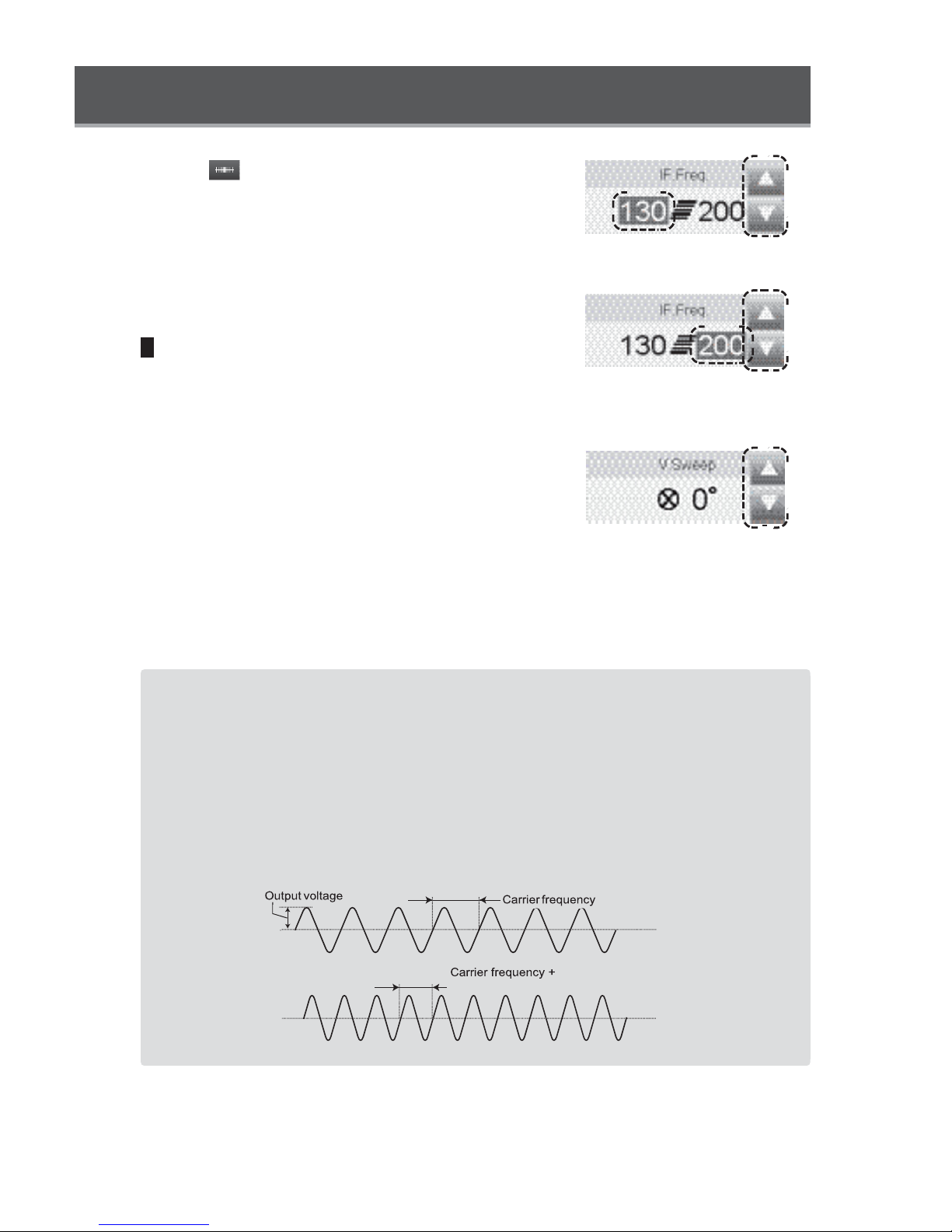
When (Sweep) is selected as the output mode
Touch the minimum frequency or maximum frequency
indication.
The selected numeric indication becomes highlighted,
and up/down keys will appear to the right of the button.
Sweep mode: Minimum
frequency setting
Set each frequency by using the up/down keys.
5
Vector sweep setting
Touch the vector sweep setting button and set the
vector sweep angle.
Set the vector sweep angle by using the up/down keys.
* If the target area is not clear, set a wide vector sweep
angle. When the vector sweep angle is wide, the
stimulation will feel gentle.
0° : No sweeping (to be used when target section is clear)
15°: 33% of area surrounded by electrodes can be
stimulated.
30°: 50% of area surrounded by electrodes can be
stimulated
45°: 100% of area surrounded by electrodes can be
stimulated
Sweep mode: Maximum
frequency setting
Parameter setting range for 4-Pole Interferential mode
Output mode: Constant, Sweep
Carrier frequency: 2 kHz, 4 kHz, 5 kHz, 8 kHz, 10 kHz
Interferential frequency: 1 to 250 Hz [1 to 10 Hz (1-Hz steps), 10 to 250 Hz (10-Hz steps)]
Vector sweep angle: 0°, 15°, 30°, 45°
Timer: 1 to 60 minutes [1 to 30 minutes (1-minute steps), 30 to 60 minutes (5-minute steps)]
Output current (peak current value): 0.5 to 100 mA (0.5-mA steps)
Output voltage (peak voltage value at 500 Ωload): 0.2 to 50 V (0.2-V steps)
Waveform:
CH1
CH2
interferential frequency

Connectable
electrodes
Usable channels
Treatment screen
1 2 3
4
Self-adhesive Electrode, Sponge Electrode,
(optional)
CH1 and CH2
1
Output mode setting button
3
Carrier frequency setting button
2
Timer setting button
4
Interferential frequency setting button

1
Output mode setting
When the output mode setting button is touched, a subwindow opens.
Touch either (Constant) or (Sweep), then
touch the OK button to close the sub-window.
2
Timer setting
When the timer setting button is touched, the up/down
keys will appear to the right of the button.
Set the treatment time by using the up/down keys.
3
Carrier frequency setting
When the carrier frequency setting button is touched,
the up/down keys will appear to the right of the button.
Set the carrier frequency by using the up/down keys.
4
Interferential frequency setting
When (Constant) is selected as the output
mode
When the interferential frequency setting button is
touched, the up/down keys will appear to the right of
the button.
Set the interferential frequency by using the up/down
keys.
Constant mode

Setting Parameters for 2-Pole Interferential Mode
When (Sweep) is selected as the output mode
Touch the minimum frequency or maximum frequency
indication.
The selected numeric indication becomes highlighted,
and up/down keys will appear to the right of the button.
Set each frequency by using the up/down keys.
Parameter setting range for 2-Pole Interferential mode
Output mode: Constant, Sweep
Carrier frequency: 2 kHz, 4 kHz, 5 kHz, 8 kHz, 10 kHz
Interferential frequency: 1 to 250 Hz [1 to 10 Hz (1-Hz steps), 10 to 250 Hz (10-Hz steps)]
Timer: 1 to 60 minutes [1 to 30 minutes (1-minute steps), 30 to 60 minutes (5-minute steps)]
Output current (peak current value): 0.5 mA to 100 mA (0.5-mA steps)
Output voltage (peak voltage value at 500 Ωload): 0.2 to 50 V (0.2-V steps)
Waveform:
Sweep mode: Minimum
frequency setting
Sweep mode: Maximum
frequency setting

Setting Parameters for EMS Mode
Connectable
electrodes
Usable channels
Treatment screen
1 2 3
Self-adhesive Electrode, Sponge Electrode,
(optional)
Surge Independent: CH1 and CH2
Surge Co-Cont, Surge Alternate: Combination of CH1 and CH2
4 5
1
Output mode setting button
3
Carrier frequency setting button
5
On/Off setting button
2
Timer setting button
4
Interferential frequency setting button

Setting Parameters for EMS Mode
1
Output mode setting
When the output mode setting button is touched, a subwindow opens.
Touch (Surge Independent), (Surge Co-
Cont), o (Surge Alternate), then touch the OK
r
button to close the sub-window.
* For Surge Co-Cont and Surge Alternate use two channels.
: Simultaneous output from 2 channels
: Alternating output from 2 channels
2
Timer setting
When the timer setting button is touched, the up/down
keys will appear to the right of the button.
Set the treatment time by using the up/down keys.
3
Carrier frequency setting
When the carrier frequency setting button is touched,
the up/down keys will appear to the right of the button.
Set the carrier frequency by using the up/down keys.
4
Interferential frequency setting
When the interferential frequency setting button is
touched, the up/down keys will appear to the right of
the button.
Set the interferential frequency by using the up/down
keys.

5
On/Off setting
When the On/Off button is touched, a sub-window
opens.
Touch the item to change, and set the parameters using
the up/down keys on the right side of the sub-window.
① ②
③ ④ ⑤ ②
①On time setting button
②Off time setting button
③Ramp up time setting button
④Hold time setting button
⑤Ramp down time setting button
⑥Timer setting button
⑦Number-of-contractions setting button
⑥
⑦
Parameter setting range for EMS mode
Output mode: Surge Independent, Surge Co-Cont, Surge Alternate
Carrier frequency: 2 kHz, 4 kHz, 5 kHz, 8 kHz, 10 kHz
Interferential frequency: 20 to 250 Hz (10-Hz steps)
On time: 0.1 to 36 sec
Ramp up time: 0 to 3 sec. (0.1-sec. steps)
Hold time: 0 to 30 sec. (0.5-sec. steps)
Ramp down time: 0 to 3 sec. (0.1-sec. steps)
Off time: 1 to 99 sec. (0.5-sec. steps)
Timer: 1 to 60 minutes [1 to 30 minutes (1-minute steps), 30 to 60 minutes (5-minute steps)]
Output current (peak current value): 0.5 to 100 mA (0.5-mA steps)
Output voltage (peak voltage value at 500 Ωload): 0.2 to 50 V (0.2-V steps)
Output
voltage
Ramp up
Hold time
Ramp down
Off time
Interferential frequency
Waveform:
On time

Setting Parameters for Russian Mode
Connectable
electrodes
Usable channels
Treatment screen
1 2 3
4
Self-adhesive Electrode, Sponge Electrode,
(optional)
Independent: CH1 and CH2
Co-Cont/Alternate: Combination of CH1 and CH2
1
Output mode setting button
3
Duty setting button
2
Timer setting button
4
On/Off setting button

1
Output mode setting
When the output mode setting button is touched, a subwindow opens.
Touch (Surge Independent), (Surge Co-
Cont), o (Surge Alternate), then touch the OK
button to close the sub-window.
* For Surge Co-Cont and Surge Alternate use two channels.
2
Timer setting
When the timer setting button is touched, the up/down
keys will appear to the right of the button.
Set the treatment time by using the up/down keys.
3
Duty setting
r
: Simultaneous output from 2 channels
: Alternating output from 2 channels
When the duty setting button is touched, the up/down
keys will appear to the right of the button.
Set the duty by using the up/down keys.

Setting Parameters for Russian Mode
4
On/Off setting
⑥
① ②
⑦
When the On/Off button is touched, a sub-window
opens.
Touch the item to change, and set the parameters using
the up/down keys on the right side of the sub-window.
①On time setting button
②Off time setting button
③Ramp up time setting button
④Hold time setting button
⑤Ramp down time setting button
⑥Timer setting button
⑦Number-of-contractions setting button
Parameter setting range for Russian mode
③ ④ ⑤ ②
Output mode: Surge Independent, Surge Co-Cont, Surge Alternate
Carrier frequency: 2.5 kHz (fixed)
Duty: 10 to 100% (10% steps)
On time: 0.1 to 36 sec
Ramp up time: 0 to 3 sec. (0.1-sec. steps)
Hold time: 0 to 30 sec. (0.5-sec. steps)
Ramp down time: 0 to 3 sec. (0.1-sec. steps)
Off time: 1 to 99 sec. (0.5-sec. steps)
Timer: 1 to 60 minutes [1 to 30 minutes (1-minute steps), 30 to 60 minutes (5-minute steps)]
Output current (peak current value): 0.5 to 100 mA (0.5-mA steps)
Output voltage (peak voltage value at 500 Ωload): 0.2 to 50 V (0.2-V steps)
Waveform:
Output
voltage
Ramp up
Hold time
Ramp down
Off time
On time
10 ms*
20 ms
Duty set at 50%
*

Setting Parameters for Hi-Voltage Mode
Connectable
electrodes
Usable channels
* When HV/DC Probes are connected, the open error detection function turns off.
Treatment screen
1 2 3
Self-adhesive Electrode, Sponge Electrode,
(optional)
Constant, Sweep, Burst, Surge Independent: CH1 and CH2
Surge Co-Cont, Surge Alternate: Combination of CH1 and CH2
4
1
Polarity/output mode setting button
3
Frequency setting button
2
Timer setting button
4
On/Off setting button
* The On/Off setting button appears only when Surge Independent, Surge Co-Cont, or Surge
Alternate is selected.
* In Hi-Voltage mode, CV is automatically set. CC cannot be selected.

Setting Parameters for Hi-Voltage Mode
1
Polarity/output mode setting
When the polarity/output mode setting button is
touched, a sub-window opens.
Select the output mode by touching the (Constant),
(Sweep), (Bur (Surge Independent)
(Surge Co-Cont), or (Surge Alternate) button.
t),
Select the polarity from , , or , then touch
the OK button to close the sub-window.
* For Surge Co-Cont and Surge Alternate use two channels.
: Simultaneous output from 2 channels
: Alternating output from 2 channels
2
Timer setting
* The set polarity applies to the
gray connection pins of the
electrode cable.
When the timer setting button is touched, the up/down
keys will appear to the right of the button.
Set the treatment time by using the up/down keys.
3
Frequency setting
When the frequency setting button is touched, the up/
down keys will appear to the right of the button.
Set the frequency by using the up/down keys.
When selecting modes other than (Sweep) as
the output mode
When the frequency setting button is touched, the up/
down keys will appear to the right of the button.
Set the frequency by using the up/down keys.
When selecting (Sweep) as the output mode
Touch either minimum frequency or maximum
frequency indication.
The selected numeric indication becomes highlighted,
and up/down keys will appear to the right of the button.
Set each frequency by using the up/down keys.
Mode other than Sweep mode
Sweep mode: Minimum
frequency setting
Sweep mode: Maximum
frequency setting

4
On/Off setting (Surge mode only)
When (Surge Independent), (Surge Co-
Cont), o (Surge Alternate) is selected, the On/Off
r
setting button appears.
When the On/Off setting button is touched, a subwindow opens.
Touch the item to change, and set the parameters using
⑥
the up/down keys on the right side of the sub-window.
①On time setting button ②Off time setting button ③Ramp up time setting button
④Hold time setting button ⑤Ramp down time setting button ⑥Timer setting button
⑦Number-of-contractions setting button
① ②
⑦
③ ④ ⑤ ②
Parameter setting range for Hi-Voltage mode
Output mode: Constant, Sweep, Burst, Surge Independent, Surge Co-Cont,
Surge Alternate
Polarity: positive, negative, alternate
Frequency:
Constant 0.5 to 200 Hz [0.5 Hz, 0.7 Hz, 1 to 10 Hz (1-Hz steps), 10 to 200 Hz (10-Hz steps)]
Sweep 1 to 200 Hz [1 to 10 Hz (1-Hz steps), 10 to 200 Hz (10-Hz steps)]
Burst 0.5 to 7 Hz [0.5 Hz, 0.7 Hz, 1 to 7 Hz (1-Hz steps)]
Surge Independent, Surge Co-Cont, Surge Alternate 20 to 200 Hz (10-Hz steps)
Pulse duration: 10 µs (fixed)*
* Pulse width at half the output voltage (500 Ωload).
On time: 0.1 to 36 sec
Ramp up time: 0 to 3 sec. (0.1-sec. steps)
Hold time: 0 to 30 sec. (0.5-sec. steps)
Ramp down time: 0 to 3 sec. (0.1-sec. steps)
Off time: 1 to 99 sec. (0.5-sec. steps)
Timer: 1 to 60 minutes [1 to 30 minutes (1-minute steps), 30 to 60 minutes (5-minute steps)]
Output voltage (peak voltage value): 0.5 to 300 V [0.5 to 100 V (0.5-V steps), 100 to 300 V (1-V steps)]
Waveform:
Output
voltage
Frequency
(Alternate polarity)

Connectable
electrodes
Usable channels
Treatment screen
1 2 3
4 5
Self-adhesive Electrode, Sponge Electrode, (optional)
Constant, Sweep, Burst, Surge Independent: CH1 and CH2
Surge Co-Cont, Surge Alternate: Combination of CH1 and CH2
1
Polarity/output mode setting button
3
Frequency setting button
5
On/Off setting button
2
Timer setting button
4
Pulse duration setting button
* The On/Off setting button appears only when Surge Independent, Surge Co-Cont, or Surge
Alternate is selected.

1
Polarity/output mode setting
When the polarity/output mode setting button is
touched, a sub-window opens.
Select the output mode by touching the (Constant),
(Sweep), (Bur (Surge Independent)
(Surge Co-Cont), or (Surge Alternate) button.
Select (Symmetrical Waveform) or (Asymmetrical Waveform).
* When symmetrical waveform is chosen, the polarity cannot
be changed.
* For Surge Co-Cont and Surge Alternate use two channels.
: Simultaneous output from 2 channels
: Alternating output from 2 channels
2
Timer setting
t),
* The set polarity applies to the
gray connection pins of the
electrode cable.
When the timer setting button is touched, the up/down
keys will appear to the right of the button.
Set the treatment time by using the up/down keys.
3
Frequency setting
When the frequency setting button is touched, the up/
down keys will appear to the right of the button.
Set the frequency by using the up/down keys.
When selecting modes other than (Sweep) as
the output mode
When the frequency setting button is touched, the up/
down keys will appear to the right of the button.
Set the frequency by using the up/down keys.
Mode other than Sweep mode

When selecting (Sweep) as the output mode
Touch either minimum frequency or maximum
frequency indication.
The selected numeric indication becomes highlighted,
and up/down keys will appear to the right of the button.
Set each frequency by using the up/down keys.
4
Pulse duration setting
When the pulse duration setting button is touched, the
up/down keys will appear to the right of the button.
Set the treatment time by using the up/down keys.
5
On/Off setting (Surge mode only)
When (Surge Independent), (Surge Co-
Cont), o (Surge Alternate) is selected, the On/Off
setting button appears.
When the On/Off setting button is touched, a subwindow opens.
Touch the item to change, and set the parameters using
the up/down keys on the right side of the sub-window.
r
⑥
Sweep mode: Minimum
frequency setting
Sweep mode: Maximum
frequency setting
① ②
⑦
③ ④ ⑤ ②
①On time setting button
②Off time setting button
③Ramp up time setting button
④Hold time setting button
⑤Ramp down time setting button
⑥Timer setting button
⑦Number-of-contractions setting button

Parameter setting range for TENS mode
Output mode: Constant, Sweep, Burst, Surge Independent, Surge Co-Cont,
Surge Alternate
Waveform setting: Symmetrical waveform, asymmetrical waveform
Polarity: positive, negative, alternate
Frequency:
Constant 0.5 to 250 Hz [0.5 Hz, 0.7 Hz, 1 to 10 Hz (1-Hz steps), 10 to 250 Hz (10-Hz steps)]
Sweep 1 to 250 Hz [1 to 10 Hz (1-Hz steps), 10 to 250 Hz (10-Hz steps)]
Burst 0.5 to 7 Hz [0.5, 0.7, 1 to 7 Hz (1-Hz steps)]
Surge Independent, Surge Co-Cont, Surge Alternate 20 to 250 Hz (10-Hz steps)
Pulse duration: 50 to 300 µs (10-µs steps)
On time: 0.1 to 36 sec
Ramp up time: 0 to 3 sec. (0.1-sec. steps)
Hold time: 0 to 30 sec. (0.5-sec. steps)
Ramp down time: 0 to 3 sec. (0.1-sec. steps)
Off time: 1 to 99 sec. (0.5-sec. steps)
Timer: 1 to 60 minutes [1 to 30 minutes (1-minute steps), 30 to 60 minutes (5-minute steps)]
Output current (peak current value): 0.5 to 100 mA (0.5-mA steps)
Output voltage (peak voltage value at 500 Ωload): 0.2 to 50 V (0.2-V steps)
Waveform:
Output
voltage
Pulse duration
Frequency

Setting Parameters for Microcurrent Mode
Connectable
electrodes
Self-adhesive Electrode, Sponge Electrode, (optional)
Usable channels
Treatment screen
1 2 3
4 5 6
CH1 and CH2
1
Phase 1 polarity setting button
3
Phase 1 frequency setting button
5
Phase 2 timer setting button
2
Phase 1 timer setting button
4
Phase 2 polarity setting button
6
Phase 2 frequency setting button
* In Microcurrent mode, electric currents of different settings can output continuously.
When using only Phase 1, set the Phase 2 timer to “0.”
* In Microcurrent mode, CC is automatically set. CV cannot be selected.

1
Phase 1 polarity mode setting
When the Phase 1 polarity setting button is touched, a
sub-window opens.
Select the Phase 1 polarity from , , or , and
touch the OK button to close the sub-window.
* The set polarity applies to the gray
connection pins of the electrode
cable.
2
Phase 1 timer setting
When the Phase 1 timer setting button is touched, the
up/down keys will appear to the right of the button.
Set the Phase 1 treatment time by using the up/down
keys.
* The timer can be set to up to 60 minutes for the total time of
Phase 1 and Phase 2.
3
Phase 1 frequency setting
When the Phase 1 frequency setting button is touched,
the up/down keys will appear to the right of the button.
Set the Phase 1 frequency by using the up/down keys.
4
Phase 2 setting
When using Phase 2, set the Phase 2 polarity, timer,
and frequency in the same manner.

Setting Parameters for Microcurrent Mode
Parameter setting range for Microcurrent mode
Polarity: positive, negative, alternate
Frequency: 0.2 to 400 Hz [0.2 Hz, 0.3 Hz, 0.5 Hz, 0.7 Hz, 1 to 10 Hz (1-Hz steps),
10 to 400 Hz (10-Hz steps)]
Pulse duty: 50% (fixed)
Timer: 1 to 60 minutes [1 to 30 minutes (1-minute steps), 30 to 60 minutes (5-minute steps),
Phase 1 + Phase 2 ≤ 60 min)]
Output current (peak current value): 10 to 750 µA (10-µA steps)
Waveform:
Output
(Alternate polarity)
Frequency
Pulse Duty:50%

Setting Parameters for Galvanic Mode
Connectable
electrodes
Usable channels
* When HV/DC Probes are connected, output is automatically set to 1/10, and the open error detection
function turns off.
* When HV/DC Probes are connected, CV is automatically set. CC cannot be selected.
Treatment screen
Sponge Electrode, (optional), HV/DC Probe (optional)
CH1 and CH2
1 2 3
1
Polarity/output mode setting button
3
Pulse duration setting button
2
Timer setting button
* The pulse duration setting button appears only when the output mode is set to Positive/Interrupted
or Negative/Interrupted.

Setting Parameters for Galvanic Mode
1
Polarity/output mode setting
When the polarity/output mode setting button is
touched, a sub-window opens.
Select (Positive/Continuous), (Negative/
Continuous), (Positive/Interrupted), or
(Negative/Interrupted), and touch the OK button to
close the sub-window.
* The set polarity applies to the gray
connection pins of the electrode
cable.
2
Timer setting
When the timer setting button is touched, the up/down
keys will appear to the right of the button.
Set the treatment time by using the up/down keys.
3
Pulse duration setting
When the pulse duration setting button is touched, the
up/down keys will appear to the right of the button.
Set the treatment time by using the up/down keys.
* The pulse duration setting button appears only when the
output mode is set to Positive/Interrupted or Negative/
Interrupted.

Parameter setting range for Galvanic mode
Output mode: Continuous, Interrupted
Polarity: positive, negative
Pulse duration (interrupted): 60 ms, 100 ms, 300 ms, 500 ms, 1000 ms
(pulse duty fixed at 95%)
Frequency (interrupted): 0.95 to 15.8 Hz
Timer: 1 to 60 minutes [1 to 30 minutes (1-minute steps), 30 to 60 minutes (5-minute steps)]
Output current (peak current value): 0.2 to 20 mA (0.2-mA steps)
Output voltage (peak voltage value at 500 Ωload): 0.1 to 10 V (0.1-V steps)
Waveform:
Continuous
Output
voltage
Interrupted
Output
voltage
Pulse duration
Pulse interval

Setting Parameters for Faradic Mode
Preparing for Ultrasound Therapy
1
Make sure the power switch for the Main Unit is
turned off.
2
Connect the power supply cord to the power supply
cord connection port on the Main Unit.
3
Connect the power supply cord to an AC power
outlet.
4
Connect one of the Ultrasound Probe (L) and
Ultrasound Probe (S) (optional), or both to the
Ultrasound Probe connection port.
* The Ultrasound Probe cable can be connected to either
connection port.
* Do not connect Ultrasound Probes of the same size to the
Main Unit at the same time.
5
Turn on the power switch for the Main Unit.
After the initial check is completed, the treatment
screen will appear.
1. To avoid the risk of electric shock, this equipment must only be
WARNING
CAUTION
connected grounded power connection.
2. MULTIPLE SOCKET-OUTLET or extension cord shall not be
connected to the SONICATOR PLUS 921.
1. In order to disconnect from a wall socket, pull the plug.
2. Do not position the SONICATOR PLUS 921 where it is difficult to

WARNING
To avoid electric shock, do not perform any operations other than the
operation of the Ultrasound Probe when your hands are wet.
Caution regarding auto contact function
● The auto contact function adjusts output to minimum levels when the Ultrasound Probe
is moved away from the treatment area (skin) but does not completely shut off output. Do
not leave the Ultrasound Probe unattended while the power switch is turned on. Be sure
to turn off the power switch when not performing a treatment with the Ultrasound Probe.
Avoid leaving ultrasound gel on the probe head. Be sure to wipe off ultrasound gel after
each use.
● To prevent burns, check the temperature of the probe head before resuming use of the
Ultrasound Probe after allowing it to stand for more than 1 minute.
● If the Ultrasound Probe is left unused for 3 minutes or more, the output will shut down
automatically.
Do not hold the head of the ultrasound probe or LED
CAUTION
area of the probe for a long period during treatment,
due to heating of these locations.

CH2
CH1
Ultrasound Therapy Screen
Treatment screen
1
⑧
2
P01
⑫
⑪
3
3
100
10:00
0.0
mA
⑬
①Treatment mode selection button
This button is used to select the treatment mode for ultrasound therapy or combination
therapy.
Touch the button to display the sub-window for selecting treatment mode.
②Parameter setting buttons
These buttons are used to set ultrasound therapy parameters.
1
Frequency setting button
3
Duty setting button
29:51
10:00
0.0
2
Timer setting button
4
Pulse frequency setting button
mA
⑦ ③
50
%
29:51
1.00
②
④
⑤
⑥
③Ultrasound channel selection button
This button is used to change the display to the treatment screen for ultrasound therapy and
combination therapy.
The channel selection button shows the treatment mode, remaining time, pause button
(during output operation only), and output level.
④Treatment mode icon
This icon indicates the treatment mode.
⑤Remaining time display
The remaining treatment time is shown.

⑥Pause button
This button appears during output operation only. It is used to pause, resume, or stop output.
When the pause button is touched, the output pauses. When the button is touched again,
the output resumes.
When the pause button is pressed and held, the output stops and the treatment ends.
⑦Output level display
The output level is shown.
⑧Program load button
This button is used to change the display to the load screen.
* The button is inoperable for the channel in output operation.
* For information on loading a program, see pages 96 to 97.
⑨Program save button
This button is used to change the display to the save screen.
* The button is inoperable for the channel in output operation.
* For information on saving a program, see pages 94 to 95.
⑩Clinical program button
This button is used to change the display to the clinical program screen.
* The button is inoperable for the channel in output operation.
* For details of clinical programs, see pages 90 to 93.
⑪Ultrasound Probe selection button
The size of the selected Ultrasound Probe and type of coupler is shown.
* When both the Ultrasound Probe (L) and Ultrasound Probe (S) is connected, size selection of the
probe is accessible by pressing this button.
* For details of the Ultrasound coupler settings, see page 99.
⑫Config button
This button is used to change the display to the setting screen.
* This button is inoperable during output operation.
* For details of the setting screen, see pages 98 to 100.
⑬Electrotherapy channel selection buttons
These buttons are used to change the display to the treatment screen for electrotherapy and
measurement mode.
* For details of electrotherapy, see pages 29 to 65. For details of measurement mode, see pages 66
to 73.

F-2
Connectable
electrodes
Ultrasound Probe (L), Ultrasound Probe (S) (optional)
Usable channels
US only
* Make sure the Ultrasound Probe to be used is connected to the Main Unit.
1
Select the US channel.
Touch the ultrasound channel selection button to
ultrasound P01
display the US channel.
2
Select the treatment mode.
Touch the treatment mode selection button.
A sub-window opens. Select Ultrasound, then
touch the OK button to close the sub-window.
Ultrasound
TENS
Comb.
Faradic
Comb.
3
Select the Ultrasound Probe to be used.
I
Comb.
Microcurrent
Comb.
Diadynamic
Comb.
L
GEL
Hi-Voltage
Comb.
Galvanic
Comb.
Traebert
Comb.
Touch the ultrasound probe selection button and
select the size of the Ultrasound Probe to be used.
* When only one Ultrasound Probe is connected, the
button cannot be selected.
* Ultrasound coupler can be set on the setting screen.
For details of the Ultrasound coupler settings, see
page 99.
Duty

4
Set the frequency.
Touch the frequency setting button to set the ultrasound
frequency.
Touch the button to toggle between “1 MHz” and “3
MHz.”
5
Set the timer.
When the timer setting button is touched, up/down
keys will appear to the right of the button.
Set the treatment time by using the up/down keys.
6
Set the duty.
When the duty setting button is touched, up/down keys
will appear to the right of the button.
Set the duty by using the up/down keys.
7
Set the pulse frequency.
3
Freq.
Time
30:00
Duty
100
MHz
%
When the pulse frequency setting button is touched,
up/down keys will appear to the right of the button.
Set the pulse frequency by using the up/down keys.
* Settings cannot be changed during output operation.
* When duty is set at 100%, settings cannot be changed.
* To save the set treatment parameters, see pages 94 to 95.
To retrieve saved treatment parameters, see pages 96 to
97.
* To use a clinical program, see pages 90 to 93.
Pulse Freq.
100
Hz

8
Apply ultrasound gel to the probe head.
* When using ointment as the ultrasound coupler, select
OTM with the GEL/OTM setting button on the setting
screen/treatment setting.
For information on GEL/OTM settings, see page 99.
9
Start output.
Turn the ultrasound intensity control dial to the right to
increase output and start treatment.
When output starts, the LED around the ultrasound
intensity control dial will light up.
* A treatment melody will play during output operation. There
will be no treatment melody if the treatment melody is set to
mute. For information on setting the treatment sound, see
page 98.
* The timer and output level settings can be changed during
output operation.
Pausing treatment
To pause treatment, touch the pause button. The output indication flashes and the output pauses.
To resume the treatment, touch the pause button again or increase the output level by operating
the ultrasound intensity control dial. The output will be produced for the remaining treatment time.
* During the pause phase of the treatment, when the ultrasound intensity control dial is set to “0”, the
treatment will end.
To end treatment
To stop treatment, either press and hold the pause button, set the ultrasound intensity control dial
to “0” or press the stop switch.
* When the stop switch is pressed, all channels in output operation stop.

10 When the timer reaches “00:00,” the end melody plays and the output stops.
*There will be no end melody if the sound level setting is set to Mute.
For information on setting end melody, see page 98.
11 Turn off the power switch for the Main Unit.
Wipe off ultrasound gel from the probe head and disconnect the Ultrasound Probe from the
Main Unit.
12 Unplug the power supply cord from the AC power outlet.
* Store the Main Unit, accessories, etc. neatly to ensure trouble-free use during the next treatment.
Note:
Basis for the measurement conditions for sound pressure level is determined as the
distance able to be reached by hand (about 60 cm away).
Parameter setting range for Ultrasound mode
Ultrasound frequency: 1 MHz, 3 MHz
Duty: 5%, 10%, 20%, 30%, 40%, 50%, 100%
Pulse frequency: 16 Hz, 48 Hz, 100 Hz
Timer: 1 to 30 minutes (1-minute steps)
Intensity (max.): 2.0 W/cm
2
(Continuous), 3.0 W/cm2 (Pulse)

Preparing for Combination Therapy
1
Make sure the power switch for the Main Unit is
turned off.
2
Connect the power supply cord to the power supply
cord connection port on the Main Unit.
3
Connect the power supply cord to an AC power
outlet.
4
Select the electrode for electrotherapy and connect
the electrode to the connection pin of the electrode
cable for CH2 that has a “Comb.” tag.
● Only rubber electrodes, self-adhesive electrodes
(optional) and vacuum electrodes(optional) can be
used for combination therapy.
* For information on using each electrode, see pages 15 to
17 and 21 to 23.

5
Attach the electrode securely close to the treatment
area.
6
Connect the electrode cable to the electrode cable
connection port for CH2.
* Only the combination of CH2 and US channels can be used
in Combination mode.
7
Connect one of the Ultrasound Probe (L) and
Ultrasound Probe (S) (optional), or both to the
Ultrasound Probe connection port.
* The Ultrasound Probe cable can be connected to either
connection port.
* Do not connect Ultrasound Probes of the same size to the
Main Unit at the same time.
8
Turn on the power switch for the Main Unit.
After the initial check is completed, the treatment
screen will appear.

Combination Therapy Screen
Treatment screen
①
⑨ ⑩ ⑪
⑭
⑫ ⑬
② ③
④
①Treatment mode selection button
This button is used to select ultrasound therapy mode or combination therapy mode.
Touch this button to display a sub-window for selecting a treatment mode.
②Electrotherapy parameter setting area
This area is used to set treatment parameters for electrotherapy.
The parameters that can be set depend on the treatment mode.
* For information on setting electrotherapy parameters, see pages 29 to 61.
* All output modes of IF-4, EMS, Russian, Hi-Voltage Surge mode, and TENS Surge mode cannot be
set for combination therapy.
③Ultrasound parameter selection area
This area is used to set treatment parameters for ultrasound therapy.
* For information on setting ultrasound therapy parameters, see pages 76 to 81.
⑮
⑤
⑥
⑦ ⑧
④Treatment mode icon
The treatment mode is indicated with an icon.
⑤Remaining time display
The remaining treatment time is shown.

⑥Pause button
This button appears only for the channel in output operation. It is used to pause, resume, or
stop the output from each channel.
When the pause button is touched, the output from the corresponding channel pauses.
When the button is touched again, the output resumes.
When the pause button is pressed and held, the output from the corresponding channel
stops and the treatment ends.
⑦Electric current output level display
The electric current output level is shown.
⑧Ultrasound output level display
The ultrasound output level is shown.
⑨Program load button
This button is used to change the display to the load screen.
* The button is inoperable for the channel during output operation.
* For information on loading a program, see pages 96 to 97.
⑩Program save button
This button is used to change the display to the screen to save programs.
* The button is inoperable for the channel in output operation.
* For information on saving a program, see pages 94 to 95.
⑪Clinical program button
This button is used to change the display to the clinical program screen.
* The button is inoperable for the channel in output operation.
* For details of clinical programs, see pages 90 to 93.
⑫Ultrasound Probe selection button
The size of the selected Ultrasound Probe is shown.
⑬Electrode selection button
The type of connected electrodes is indicated with an icon.
When the Vacuum Unit is connected, this button is used to switch between the electrodes
connected to the Main Unit and Vacuum Electrodes.
* The button is inoperable for the channel during output operation.
⑭Config button
This button is used to change the display to the setting screen.
* This button is inoperable during output operation.
* For details of setting screen, see pages 98 to 100.
⑮Electrotherapy channel selection button
This button is used to change the display to the treatment screen for electrotherapy and
measurement mode.
* For details of electrotherapy, see pages 29 to 65. For details of measurement mode, see pages 66 to 73.

F-2
Connectable
electrodes
Electrotherapy: Sponge Electrode, (optional), HV/DC Probe
(optional)
Ultrasound therapy: Ultrasound Probe (L), Ultrasound Probe (S) (optional)
Usable channels
Combination of CH2 and US only
* Make sure the Ultrasound Probe is connected to the Main Unit.
1
Select the US channel.
Touch the ultrasound channel selection button to
display the US channel.
2
Select the treatment mode.
Touch the treatment mode selection button.
A sub-window opens. Select the combination
therapy mode to use, then touch the OK button to
close the sub-window.
* IF-4, EMS, and Russian modes cannot be set for
combination therapy.
3
Select the Ultrasound Probe to be used.
ultrasound P01
Ultrasound
TENS
Comb.
I
Comb.
Microcurrent
Comb.
L
GEL
Hi-Voltage
Comb.
Galvanic
Comb.
Touch the electrode selection button and select
the size of the Ultrasound Probe to be used.
* When only one Ultrasound Probe is connected,
the button cannot be selected.
* Ultrasound coupler can be set on the setting screen.
For details of the ultrasound coupler settings, see
page 99.
Duty

4
Set the treatment parameters for electrotherapy.
The parameters that can be set depend on the
treatment mode set.
* Surge Independent, Surge Co-Cont, and Surge Alternate
modes for Hi-Voltage and TENS cannot be used for
combination therapy.
* For information on setting electrotherapy parameters, see
pages 29 to 61.
* The set polarity applies to the Ultrasound Probe side.
* During combination therapy, the current output will
automatically be set to CV mode.
5
Set the treatment parameters for ultrasound
therapy.
* For information on setting ultrasound therapy parameters,
see pages 76 to 81.
6
Set the timer.
When the timer setting button is touched, up/down
keys will appear to the right of the button.
Set the treatment time by using the up/down keys.
* To save the set treatment parameters, see pages 94 to 95.
To retrieve saved treatment parameters, see pages 96 to
97.
* To use a clinical protocol, see pages 90 to 93.
7
Apply ultrasound gel to the probe head.
* When using ointment as the ultrasound coupler, select OTM
with the GEL/OTM setting button on the setting screen/
treatment setting.
For information on the GEL/OTM setting, see page 99.

8
Start ultrasound output.
Turn the ultrasound intensity control dial to the right to
increase output and start treatment.
When output starts, the LED around the ultrasound
intensity control dial will light up.
* A treatment melody will play during output operation. There
will be no treatment melody if the treatment melody is set to
mute. For information on setting the treatment sound, see
page 98.
* The timer and output level settings can be changed during
output operation.
9
Start the output for electrotherapy.
Turn the current intensity control dial for CH2 to the
right to set the output level.
When output starts, the pause button will appear in the
channel selection button for CH2. The LED around the
current intensity control dial will light up.
* The settings for the timer, output level, and parameters
can be changed during output operation (some parameters
cannot be changed).
* Note that if the pulse duration is changed during output
operation, the stimulation felt by the patient changes.
Pausing treatment
To pause treatment, touch the pause button. The output indication flashes and the output pauses.
To resume the treatment, touch the pause button again or increase the output level by operating
the ultrasound intensity control dial. The output will be produced for the remaining treatment time.
* During the pause phase of the treatment, when the ultrasound intensity control dial is set to “0”, the
treatment will end.

To end treatment
To stop treatment, either press and hold the pause button or set the ultrasound intensity control
dial to “0” or press the stop switch.
* When the stop switch is pressed, all channels in output operation stop.
10 When the timer reaches “00:00,” the end melody plays and the output stops.
*There will be no end melody if the sound level setting is set to Mute.
For information on setting end melody, see page 98.
11 Turn off the power switch for the Main Unit
Wipe off ultrasound gel from the probe head and disconnect the Ultrasound Probe from the
Main Unit.
12 Unplug the power supply cord from the AC power outlet.
* Store the Main Unit, accessories, etc. neatly to ensure trouble-free use during the next treatment.
CAUTION
• Avoid short circuits between the Self-adhesive Electrode and Ultrasound Probe head.
• Set the output level low at the beginning and increase gradually.
• Do not perform combination therapy in water.
• When performing combination therapy, make sure the Ultrasound Probe head is in firm
contact with the skin of the treatment area. Otherwise, electric current density will increase
in certain areas and may lead to electric shock or burns.
• The maximum electric current density must be kept below 2 mArms/cm² during combination
therapy. Note that the electric density of the Ultrasound Probe (S) [size: 16 mm] may exceed
2 mArms/cm². Adjust the output to appropriate levels and do not allow electric current density
to exceed this limit.

Display of Clinical Program Screen
Clinical program selection screen
⑤
①
②
①Upper-/lower-body selection button
This button is used to change the treatment area of the body.
Press the button to toggle between the upper body and lower body.
②Treatment area selection buttons
These buttons are used to select the treatment area.
③Clinical program list
This area displays the names of clinical programs associated with the selected treatment
area.
④Treatment program selection buttons
These buttons are used to select the treatment program.
Press a button to change the display to the corresponding treatment guidance screen.
⑤Back button
This button returns the display to the treatment screen.
③ ④

Treatment guidance screen
①
⑥
② ⑤ ③ ④
①Treatment area display
This screen area shows treatment areas.
Blue or green square: This indicates the electrode attachment position for electrotherapy.
Orange area: This shows the ultrasound therapy area.
②Parameter display
This screen area shows the parameters of the treatment program.
③Treatment guidance
This screen area displays information on the treatment program.
④OK button
This button is used to confirm the selection of the treatment program.
Touch this button to change the display to the treatment program.
⑤Cancel button
This button returns the display to the clinical program selection screen.
If the polarity is set, a “+” or “-” sign is also indicated.
When two channels are used, the squares are displayed in different
colors to make it possible to distinguish channels.
⑥Back button
This button returns the display to the treatment screen.

p
Operation of Clinical Program
Clinical programs are reference examples and should not be considered the
CAUTION
* Make sure the electrode and Ultrasound Probe used are connected to the Main Unit.
* When using a Vacuum Electrode, turn on the power switch for the Vacuum Unit and attach the Vacuum
Electrode to the treatment area.
most suitable programs for specific indications.
When performing a treatment, qualified persons should determine the program
based on the
atient’s condition and symptoms.
1
Select the channel to be used.
Touch the channel selection button and display the
channel to be used.
* The clinical program button is inoperable for the channel
in output operation. Be sure to select a channel that is
not in use.
2
Display the clinical program screen.
Touch the clinical program button to display the
clinical program selection screen.
3
Select the treatment area.
Touch the upper-/lower-body selection button and
the treatment area selection button, then select the
treatment area.
Carrier

4
Select the treatment program.
After the treatment area is selected, the right half of
the screen will display the names of clinical programs
based on the treatment area selected.
Touch the desired treatment program from the
programs available for the indications to be treated.
The display changes to the treatment guidance screen.
* In the case of treatment programs that require use of
a combination of channels (IF-4 or Surge Co-Cont and
Alternate modes for EMS, Russian, Hi-Voltage, and TENS,
or Combination), an error sound is generated if one of the
combination channels is in use and the program cannot be
selected.
* Treatment program can’t be specified for the active channels.
* When ultrasound channel is selected and the clinical
program screen is displayed, treatment program of
electrotherapy can’t be selected.
5
Attach the electrode to the treatment area.
Confirm the parameters and treatment guidance, then
attach the electrode as indicated in the treatment area
display.
* Blue or green square:
This indicates the electrode attachment position for
electrotherapy.
If the polarity is set, a “+” or “-” sign is also indicated.
If two channels are used, the squares are displayed in
different colors to make it possible to distinguish channels.
Orange area: This shows the ultrasound treatment area.
* To select a treatment program once again, touch the cancel
button to return to the clinical program selection screen.
6
Start output.
Touch the OK button to change the display to the
treatment screen. Turn the intensity control dial for the
selected channel to set the output level.
* For information on operation during output operation, see
the pages describing corresponding treatment modes.
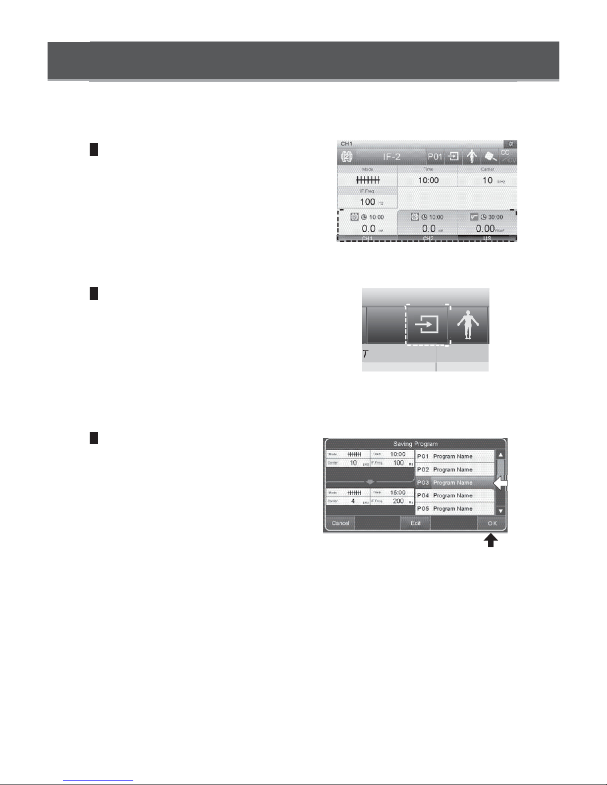
Saving Programs
Up to 10 programs can be saved for each treatment mode
1
Select a channel.
Touch the channel selection button to display
the channel for which the parameters to be
saved are set.
2
Display the save screen.
Touch the program save button to display the
sub-window.
3
Select the program number for the program
to be saved.
In the program list on the right side of the
screen, touch the program number for the
program to be saved.
Confirm the parameters and touch the OK
button to save the program.
* The upper side of the screen on the left side
shows the parameters to be saved. The lower side
displays the parameters currently saved in the
selected program number.
* To stop saving the program, touch the cancel
button.
P01
ime
②
①

To rename a program
Touch the edit button in the program save subwindow to change the display to the program
name editing screen.
Use the keyboard to rename the program. Touch
OK to confirm the change and to return to the subwindow.
* To cancel renaming, touch the back button at the
upper right corner of the screen.
* To enter a signed character, press and hold the
desired key to display candidate characters.
To cancel the input, touch
×
.

Loading Programs
1
Select the channel.
Touch the channel selection button to display
the channel for which a previously saved
program is to be loaded.
2
Display the loading screen.
Touch the program load button to display the
sub-window.
3
Select the program number of the program
to be loaded.
In the program list, select the program number
to be loaded.
Confirm the parameters and touch the OK
button to load the program.
* The upper left side of the screen shows the current
parameter setting and the lower side displays the
newly selected parameters ready to be uploaded.
* To stop loading the program, touch the cancel
button.
P01
Time
②
①

4
The program number display.
After the program is loaded, the display returns
to the treatment screen. Confirm that the
program load button indicates the program
number of the loaded program.
* If any parameters in the loaded program have
changed, the color of the program number display
will change.
P03
P03

Setting Screen
Screen/Sound screen
Config.
A
②
④
⑧
⑤
⑨
Brightness
5
4
3
①
2
1
⑩
Initialization
①Brightness setting buttons
These buttons are used to set screen brightness.
②Key sound setting button
This button is used to set the volume of the key sound.
Touch this button to display a sound level setting sub-window.
③Error sound setting button
This button is used to set the volume of the error sound.
Touch this button to display a sound level setting sub-window.
③
A
⑥
⑦
[Sound level setting sub-window]
④Treatment melody selection button
This button is used to select the type of melody to play during treatment.
⑤Treatment melody sound level setting button
This button is used to set the volume of the treatment melody.
Touch this button to display a sound level setting sub-window.
⑥End melody selection button
This button is used to select the type of melody to play at the end of treatment.
⑦End melody sound level setting button
This button is used to set the volume of the end melody.
Touch this button to display a sound level setting sub-window.
⑧Contact sound setting button
This button is used to set the contact sound to play during ultrasound therapy.
A sound plays when the Ultrasound Probe is in contact with the treatment area.
A sound plays when the Ultrasound Probe is not in contact with the treatment area.

⑨Contact sound level setting button
This button is used to set the volume of the contact sound.
Touch this button to display a sound level setting sub-window.
⑩Initialization button
This button returns settings and all program content to factory set conditions.
⑪OK button
This button finalizes the settings and returns the display to the treatment screen.
US Indication screen
Config.
GEL/OTM
W/cm2 W
③
Initialization
W/cm
①GEL/OTM setting button
This button is used to set the type of ultrasound coupler. [GEL, OTM (ointment)]
②Unit setting button
This button is used to set the measurement unit of ultrasound output. [W/cm
③Initialization button
This button returns settings and all program content to factory set conditions.
④OK button
This button finalizes the settings and returns the display to the treatment screen.
GEL
①
2
②
O K
④
2
, W]

Setting Screen
Language screen
Config.
①
English
Italiano
②
Initialization
①Language setting button
These buttons are used to select the language of the display.
Set the language to any of the following nine languages:
English, German, French, Italian, Spanish, Portuguese, Turkish, Vietnamese, or Chinese
Deutsch
Espanol
Francais
Portugues
Tieng Viet
O K
③
②Initialization button
This button returns settings and all program content to factory set conditions.
③OK button
This button finalizes the settings and returns the display to the treatment screen.

Error Screen
● Error 1: Open error
This error is displayed if the electrode or
Ultrasound Probe is disconnected from the
Main Unit or if the electrode detaches from the
treatment area.
If this error occurs, connect the electrode or
Ultrasound Probe securely to the Main Unit.
Also, confirm that the electrodes are attached
securely to the treatment area.
* This error will not be display when using HV/
DC Probes or when in Microcurrent mode or
Combination mode.
* This error will not be display when CV is set.
● Error 2: Overcurrent error
This error will be displayed when there is a
decline in amount of resistance, such as when
electrodes make contact with each other.
Check to make sure the electrodes are properly
attached to the treatment area.
* This error will not be displayed in Microcurrent mode.
● Error 3: Ultrasound probe temperature error
This error is displayed when the probe head
becomes extremely hot.
Terminate treatment and restart when the probe
head has cooled down.
● Error 4: Probe error
This error is displayed if a broken wire inside the
Ultrasound Probe is detected.
If this error occurs, replace the Ultrasound
Probe.
* When two Ultrasound Probes are connected to the
Main Unit, disconnect both probes and reset the
probe error.
● Error 5: System error
This error is displayed if the Main Unit generates
any abnormality.
Turn off the Main Unit, then turn it back on.
Error 1
OK
Error 2
OK
Error 3
OK
Error 4
OK
Error 5

● Always consider EMC issues when using electronic medical equipment. Be sure to observe the
EMC information provided in the accompanying document when installing and using the product.
● Using a mobile or portable RF communication device may affect the operation of electronic
medical devices.
● Cable lengths ①Ultrasound Probe (L): 2.0 m ②Ultrasound Probe (S): 2.0 m
③Electrode Cable: 2.0 m ④HV/DC Probe: 2.09 m
⑤Power Supply Cord: 2.44 m
● Using accessory products other than replacement parts sold by the Mettler Electronics may increase
product emissions and decrease immunity.
● Avoid using the product when it is placed next to or on top of other equipment. If the product
must be placed next to or on top of other equipment, make sure the product and other equipment
function properly before use.
Guidance and manufacturer’s declaration — electromagnetic emissions
This unit is intended for use in the electromagnetic environment specified below.
The customer or the user of this unit should assure that it is used in such an environment.
Emissions test Compliance Electromagnetic environment — guidance
RF emissions
CISPR 11
RF emissions
CISPR 11
Harmonic emissions
IEC 61000-3-2
Voltage fluctuations/
flicker emissions
IEC 61000-3-3
Group 1
Class B
Class A
Complies
This unit uses RF energy only for its internal
function. Therefore, its RF emissions are very
low and are not likely to cause any interference in
nearby electronic equipment.
This unit is suitable for use in all establishments,
including domestic establishments and those directly
connected to the public low-voltage power supply
network that supplies buildings used for domestic
purposes.

Guidance and manufacturer’s declaration — electromagnetic immunity
This unit is intended for use in the electromagnetic environment specified below. The customer or
the user of this unit should assure that it is used in such an environment.
Immunity test
IEC 60601-1-2
test level
compliance
level
Electromagnetic environment
— guidance
EIectrostatic
discharge (ESD)
IEC 61000-4-2
EIectrical fast
transient/burst
IEC 61000-4-4
Surge
IEC 61000-4-5
Voltage dips, short
interruptions and
voltage variations on
power supply input
lines
IEC 61000-4-11
±6 kV contact
±8 kV air
±2 kV for
power supply
lines
±1 kV for
input/output
lines
±1 kV line(s) to line(s)
±2 kV line(s) to earth
T
<5%U
for 0.5 cycle
40%U
for 5 cycles
70%U
for 25 cycles
<5%U
for 5 sec
(>95% dip in UT)
T
(60% dip in UT)
T
(30%dip in UT)
T
(>95% dip in UT)
±2 kV for
power supply
lines
Floors should be wood, concrete
or ceramic tile. If floors are covered
with synthetic material, the relative
humidity should be at least 30 %.
Mains power quality should be that
of a typical commercial or hospital
environment.
Mains power quality should be that
of a typical commercial or hospital
environment.
Mains power quality should be that
of a typical commercial or hospital
environment. If the user of this
unit requires continued operation
during power mains interruptions,
it is recommended that this unit be
powered from an uninterruptible
power supply or a battery.
Power frequency
(50/60 Hz)
magnetic field
IEC 61000-4-8
NOTE 1 UT is the a.c. mains voltage prior to application of the test level.
NOTE 2 To prevent electrostatic discharge, the operator must remove any static charge from his or
her body before connecting or disconnecting the connector near the symbol .
3 A/m
Power frequency magnetic fields
should be at levels characteristic
of a typical location in a typical
commercial or hospital environment.

Guidance and manufacturer’s declaration — electromagnetic immunity
This unit is intended for use in the electromagnetic environment specified below. The customer or
the user of this unit should assure that it is used in such an environment.
Immunity test
IEC 60601-1-2
test level
compliance
level
Electromagnetic environment
— guidance
Conducted RF
IEC 61000-4-6
Radiated RF
IEC 61000-4-3
NOTE 1 At 80 MHz and 800 MHz, the higher frequency range applies.
NOTE 2 These guidelines may not apply in all situations. Electromagnetic propagation is affected by
3 Vrms
150 kHz
~80 MHz
3 V/m
80 MHz
~2.5 GHz
absorption and reflection from structures, objects and people.
3 Vrms
3 V/m
Portable and mobile RF communications equipment
should be used no closer to any part of this unit.
including cables, than the recommended separation
distance calculated from the equation applicable to
the frequency of the transmitter.
Recommended separation distance
d = 1.2 P
d = 1.2 P 80 MHz to 800 MHz
d = 2.3 P 800 MHz to 2.5 GHz
where P is the maximum output power rating of the
transmitter in watts (W) according to the transmitter
manufacturer and d is the recommended separation
distance in metres (m).
Field strengths from fixed RF transmitters, as
determined by an electromagnetic site survey,
should be less than the compliance level in each
frequency range.
Interference may occur in the vicinity of equipment
marked with the following symbol:
b
a
a Field strengths from fixed transmitters, such as base stations for radio (cellular/cordless) telephones
and land mobile radios, amateur radio, AM and FM radio broadcast and TV broadcast cannot be
predicted theoretically with accuracy. To assess the electromagnetic environment due to fixed RF
transmitters, an electromagnetic site survey should be considered. If the measured field strength in
the location in which this unit is used exceeds the applicable RF compliance level above, this unit
should be observed to verify normal operation. If abnormal performance is observed, additional
measures may be necessary, such as reorienting or relocating this unit.
b Over the frequency range 150 kHz to 80 MHz, field strengths should be less than 3 V/m.

Recommended separation distances between portable and mobile RF
communications equipment and this unit
This unit is intended for use in an electromagnetic environment in which radiated RF disturbances are
controlled. The customer or the user of this unit can help prevent electromagnetic interference by maintaining
a minimum distance between portable and mobile RF communications equipment (transmitters) and this
unit as recommended below, according to the maximum output power of the communications equipment.
Rated maximum output
power of transmitter
W
0.01 0.12 0.12 0.23
0.1 0.38 0.38 0.73
Separation distance according to frequency of transmitter m
150 kHz to 80 MHz
d = 1.2 P
80 MHz to 800 MHz
d = 1.2 P
800 MHz to 2.5 GHz
d = 2.3 P
1 1.2 1.2 2.3
10 3.8 3.8 7.3
100 12 12 23
For transmitters rated at a maximum output power not listed above, the recommended separation
distance d in metres (m) can be estimated using the equation applicable to the frequency of the
transmitter, Where P is the maximum output power rating of the transmitter in watts (W) according to
the transmitter manufacturer.
NOTE 1 At 80 MHz and 800 MHz, the separation distance for the higher frequency range applies.
NOTE 2 These guidelines may not apply in all situations. Electromagnetic propagation is affected by
absorption and reflection from structures, objects and people.

1333 South Claudina Street • Anaheim, CA 92805, U. S. A.
Toll Free: (800) 854–9305 • Telephone: (714) 533–2221 • FAX: (714) 635–7539
Web Site: http://www.mettlerelectronics.com • Email: mail@mettlerelectronics.com
 Loading...