

TABLE
OF
CONTENTS
Servicing
Information:
人
Drawings
Block
A/D
Diagram
Control
Logic
Timer/Display
P/S
-
R/F
Board
A/D
Control
Board
Timer/Display
P/S
-
R/F
Board
Diagram
Logic
Diagram
Schematic
Assembly
Board
Assembly
Assembly
7
2/92
254)
1R6:18
It
is
recommended
706
be
performed
technicians
for
the
this
device.
and
prompt
INTRODUCTION
that
all
at
the
factory
the
appropriate
and
efficient
servicing
where
equipment
repair
and
of
the
Sonicator
experienced
are
available
recalibration
of
Should
factory
guidance
component
parts
at
the
the
entire
This
maintenance
sufficient
to
function
and
the
devices
it
not
for
repair,
to
locate
level.
list
at
the
factory
unit
service
guidance
to
insure
in
performance
listed
Regulations).
The
preventive
procedures
qualified
electronic
This
thoroughly
If
there
in
the
Department
factory
in
as
much
provided
service
measurement
manual
before
is
any
accomplishment
at
with
an
detail
be
possible
this
manual
potential
Major
end
as a secondary
to
the
manual
accordance
components,
of
this
factory.
is
to
that
the
manual,
designed
qualified
Sonicator
with
standards
in
21
CFR
1050.10
and
corrective
herein
personnel
only
equipment.
should
be
read
attempting
doubt
as
to
of
repairs,
the
factory,
explanatory
as
possible.
the
or
to
return
offers
problems
should
alternative
to
service
applicable
for
ultrasound
(Code
maintenance
should
be
using
and
understood
any
servicing
correct
contact
return
note
describing
the
device
the
necessary
to
the
major
as
listed
to
in
be
repaired
returning
provide
technicians
706
continues
specifications
therapy
of
Federal
performed
the
recommended
procedures.
course
the
the
unit
the
of
Service
to
problem
to
the
the
by
action
the
SPECIFICATIONS
Input:
Frequency:
Pulse
Pulse
Temporal
Indication
APPLICATOR:
Ceramic:
Frequency:
Effective
120VAC
Repetition
+
1.0
MHz
Duration:
Peak/Average
Accuracy:
Barium
1.0
MHz + 5%
Radiating
10%,
60Hz,
+
Rate:
2
msec
+
maximum
100
20%
Titanate
Area
.5-amp
5%
Hz
+
+
20%
Intensity
for
(ERA):
20%
Ratio:
any
10
cm?
max.
5
reading
+
20%
+
20%
above
10%
of
the
Type:
Beam
TIMER:
Accuracy:
Maximum
W
W/cm?
CW
msec
ERA
Collimating
Non-uniformity
+0.5
+10%
+1.0
Treatment
-
watts
-
watts
-
continuous
-
milliseconds
Area
-
effective
Ratio:
minutes
for
minutes
5
to
for
10
for
Time:
ABBREVIATIONS
per
square
waveform
radiating
centimeter
6.0
max.
times
minutes
times
29
less
greater
minutes
area
than
than
A/D
Ρ/5
R/F
BNR
Coll
5
minutes
10
minutes
-
analog-to-digital
-
power
-
radio
-
beam
-
collinating
supply
frequency
nonuniformity
ratio
S/N
-
serial
number
MHz
-
megahertz
.
Servicing
qualified
.
This
attempting
.
Use
other
hazardous
.
Line
of
service
manual
of
controls,
than
supply
any service
those
exposure
when connected
power
.
Measure
connection
the
ground
.
Do
than a few
source
ring
not
the
jack
around
pin.
operate
seconds.
automatically
unloaded.
the
Sonicator
technicians
should
be
adjustments,
specified
voltages
to
the
during
ground
and
the
piezoelectric
Results
the
should
unit
The
terminate
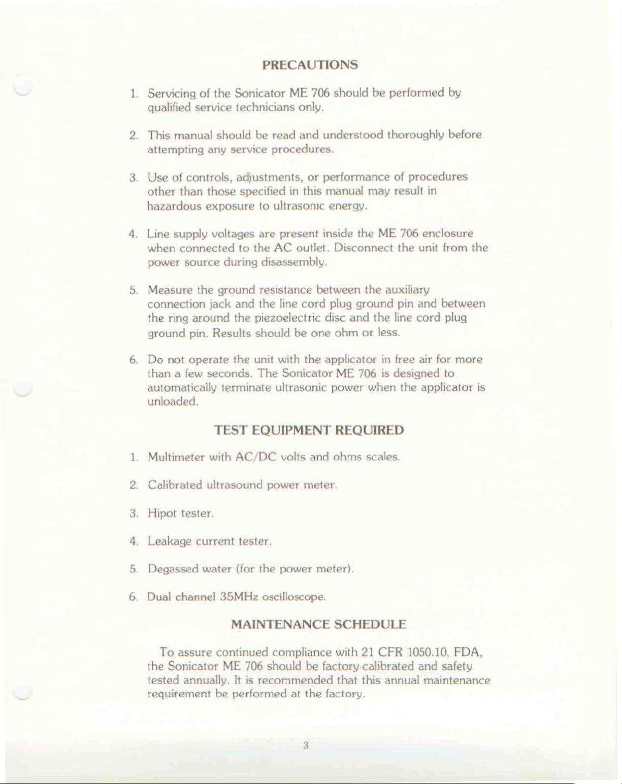
PRECAUTIONS
ME
706
only.
read
and
understood
procedures.
or
performance
in
this
manual
to
ultrasonic
are
present
AC
disassembly.
resistance
the
line
with
Sonicator
ultrasonic
inside
outlet.
between
cord
disc
be
one
the
applicator
should
energy.
be
may
the
ME
Disconnect
the
plug
ground
and
the
ohm
or
less.
in
ME
706
is
power
when
performed
thoroughly
of
procedures
result
in
706
enclosure
the unit
auxiliary
pin
and
line
cord
free
air
for
designed
the
applicator
by
before
from
the
between
plug
more
to
is
.
Multimeter
.
Calibrated
.
Hipot
.
Leakage
.
Degassed
.
Dual
the
tested
requirement
tester.
channel
To
assure
Sonicator
annually.
TEST
with
AC/DC
ultrasound
current
water
tester.
(for
35MHz
MAINTENANCE
continued
ME
It
be
performed
EQUIPMENT
volts
power
the
power
oscilloscope.
compliance
706
should
is
recommended
at
REQUIRED
and
ohms
scales.
meter.
meter).
SCHEDULE
with
21
CFR
be
factory-calibrated
that
this
the
factory.
1050.10,
annual
FDA,
and
safety
maintenance
GENERAL:
The
Sonicator
ultrasound
four
printed
panel
control,
subassemblies.
the
end
therapy
circuit
membrane
and
inter/connections.
of
this
EQUIPMENT
ME
706
device
boards,
switch
Refer
manual.
to
DESCRIPTION
is a single
with a built-in
power
assembly,
the
appropriate
unit,
transformer
main
This
section
molded
plastic
applicator.
assembly,
power
drawings
switch,
briefly
describes
in
enclosed
It
consists
control
intensity
the
appendix
of
these
at
MAJOR
SUBASSEMBLIES:
P/S - R/F
circuits,
regulator,
timer
RFI
A/D
pulse
5-volt
Timer
logic,
meter
(CW
Buzzer Board - small
Control
clock
filters.
Control
oscillator,
regulated
Display
timer
selection
or
two
PULSE),
Applicator - an
piezoelectric
cable,
to
strain-relief
the
RF
generator
Board - contains
regulated
overload
reference,
Board - contains
power
power
12-volt
sensor,
AC
indicator
supply.
Board - contains
logic,
output
timer
indicators
power
pcb
containing
integrated
ceramic
disc
and
connector.
at
the
unit
display,
(W
on reset
in a molded
P/S - R/F
enclosure.
the
power
power
RF
power
input
the
the
or
consisting
supplies,
level
line
fuses,
analog-to-digital
scaling
timer
power
W/cm?),
indicator
and
overload
buzzer
of a glass-coated
plastic
It
is
connected
board
supply,
switching
sensor
and
input
converter,
adjustment,
keyboard
mode
signal
entry
display,
indicators
controller.
control
handle
directly
within
the
RF
circuit,
line
and
a
circuit.
with
OTHER
The
and
generator
COMPONENTS:
membrane
power
front
SUBASSEMBLY
All
subassemblies
connectors.
plugs
interlock
without
keys
switch,
transformer
housing.
CONNECTIONS:
are
interconnected
The
connectors
excessive
are
provided
intensity
are
all
mounted
control,
cannot
force,
or
where
on
with
be
connected
obvious
necessary.
power
and
cable
error.
switch
under
the
assemblies
to
the
wrong
Connector
and
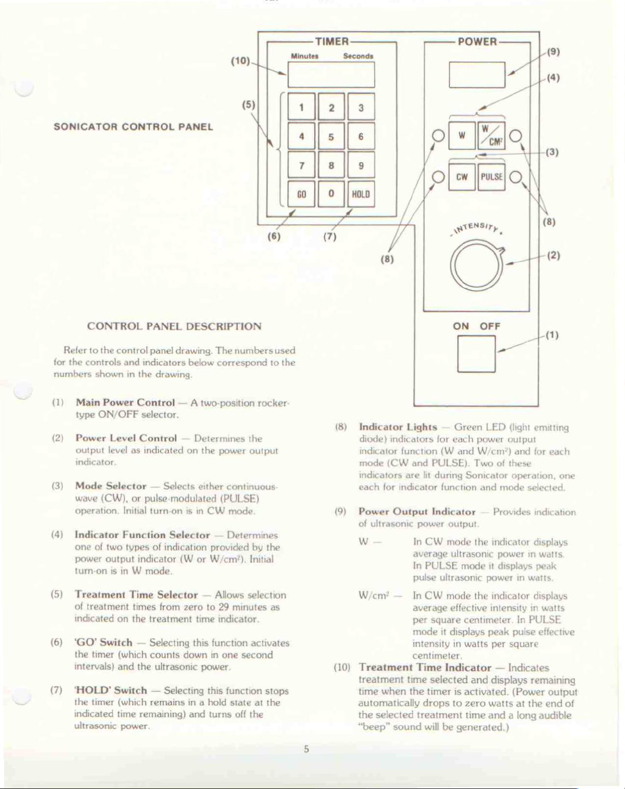
SONICATOR
CONTROL
PANEL
(10)
| 4
(>
(5)
Nile
Minutes
는
7
co
(6)
TIMER
Seconds
İzle
ls
o]
8 9
(|
O
(7)
ies
но
/
Ol
/
POWER
[n
w
ew
RENS,
o
<
м
WO
=
PMSE
.
A
À
n
Lo
=
(8)
©
(3)
CONTROL
Reler
to
the
for
the
controls
numbers shown
(1)
Main
Power
type
ON/OFF
(2)
Power
output
indicator.
(3)
Mode
wave
operation.
(4)
Indicator
one
power
turn-on
Level
level as
Selector — Selects
(CW),
of
two
output
is
PANEL
control
panel
and
indicators
in
the
Control — A
selector.
Control — Determines
indicated
or
pulse-modulated
Initial
turn-on
Function
types
of
A
indicator
+
in W mode.
DESCRIPTION
drawing.
below
drawing,
on
is
in
Selector — Determines
indication
(W
or
The
numbers
correspond
two-position
the
the
power
output
either
continuous-
(PULSE)
CW
mode
provided
W/cm?).
by
Initial
used
to
the
rocker-
the
2
(8)
(9)
(8)
Indicator
diode)
indicator
mode
indicators
each
Power
of
M
indicators
(CW
for
indicator
Output
ultrasonic
ON
Lights — Green
for
each
function
are
(W
and
and
PULSE).
lit
during
Indicator — Provides
power
In
CW
average
In
PULSE
pulse
Sonicator
function
output
mode
ultrasonic
mode
ultrasonic
OFF
LED
power
W/cm®*)
Two
of
and
mode
the
indicator
power
it
displays
power
ATO
+
ンー
(light
emitting
output
and
for
these
operation,
selected,
indication
displays
in
in
watts.
(1)
each
one
watts
peak
(5)
(6)
(7)
Treatment
of
treatment
indicated
‘GO’
the
timer
intervals)
‘HOLD’
the
timer
indicated
ultrasonic
Time
times
on
the
Switch — Selecting
(which
and
the
Switch — Selecting
(which
time
remaining)
power.
Selector — Allows
from
zero
to
29
treatment
counts
ultrasonic
remains
time
this
function
down
in
power.
this
in a hold
and
turns
indicator.
one
function
state
selection
minutes
activates
second
at
off
the
as
stops
the
W/cm?
(10)
Treatment
treatment
time
automatically
the
“beep”
—
In
average
per
mode
intensity
centimeter.
time
when
the
selected
sound
CW
mode
the
indicator
effective intensity
square
Time
selected
timer
drops
treatment
will
centimeter.
it
displays
in
Indicator — Indicates
is
to
be
generated.)
peak
watts
per
and
displays
activated.
zero
watts
time
and a long
displays
in
In
PULSE
pulse
square
remaining
(Power
at
the
watts
effective
output
end
of
audible
OPERATING
INSTRUCTIONS
Refer
to
operating
indicator
1.
Connect
60Hz
number
receptacle.
Energize
Enter
the
SELECTOR
a.
For
Example:
b.
For
Example:
c.İf
an
POWER
Select
by
pressing
the
control
procedures,
the
unit
the
unit
treatment
(5).
times
10
up
For 9 minutes,
to
29
For
incorrect
panel
for
shown
to
an
by
pressing
time
The
to 9 minutes,
minutes,
15
minutes,
time
CONTROL
continuous-wave
the
appropriate
drawing.
example
in
the
appropriately
(1),
drawing.
the
using
treatment
the
time
enter
enter
enter a ‘1’
enter a ‘1’
is
entered
(1)
and
reselect
(CW)
or
pulse-modulated
MODE
Numbers
indicate
grounded
MAIN
in
the
POWER
the
TREATMENT
must
‘0’
a ‘0’
or
accidentally,
be
entered
followed
then a ‘9’.
‘2’
followed
the a ‘5°.
by
cycle
the
desired
SELECTOR
following
control
120
VAC,
CONTROL
TIME
using
the
second
by
the
the
treatment
(PULSE)
(3)
function.
or
(1).
two
second
MAIN
mode
to
digits.
digit.
digit.
time.
the
left.
Select
the
desired
appropriate
(W
or
W/cm’).
Immerse
Press
power
a.
Treatment
pressing
the
the
‘GO’
output.
the
INDICATOR
b.
Restart
will
c.A
treatment
d.
If
the
applicator
time
Adjust
power
the
commence
buzzer
treatment
is
remaining.
the
POWER
output
INDICATOR
power
INDICATOR
ultrasound
applicator
SWITCH
time
(and
power
‘HOLD’
(10)
unit
will
by
pressing
SWITCH
indicate
countdown
automatically
time.
is
interrupted
head,
the
The
buzzer
output
LEVEL
level as
indicated
(9).
output
indication
FUNCTION
(6)
to
initiate
output)
(7).
the
the
from
sounds
at
due
will
sound
power
CONTROL
on
SELECTOR
head
treatment
can
The
time
‘GO’
the
time
the
to
to
will
the
POWER
by
pressing
in
water.
be
stopped
TREATMENT
remaining.
SWITCH
remaining.
end
of
the
lack
of
four
or
five
then
drop
(2)
to
the
OUTPUT
the
(4)
switch
time
and
by
(6).
The
selected
coupling
times
to
zero
desired
TIME
timer
at
the
indicating
watts.
that

GENERAL:
The
remainder
calibration
Sonicator
with
the
beginning
For
the
appropriate
manual.
procedures,
ME
descriptions
of
theory
drawings
SERVICING
of
706.
this
manual
of
operation
the
manual
and
The
technician
and
located
INFORMATION
contains
troubleshooting
should
operating
before
and
in
instructions
attempting
calibration
the
appendix
the
theory
guidelines
be
thoroughly
presented
to
service
sections,
at
the
of
operation,
for
the
familiar
at
the
device.
refer
to
end
of
this
the
the
THEORY
Timer
Power
OF
OPERATION
Display
programmed
entry
digits
timer
to
(as
output
Enable
the
timer
discussed
TREATMENT
timer,
SWITCH.
‘HOLD’
coupling
selected
the
treatment
The
SWITCH,
at
the
treatment
INDICATOR
timer,
the
approximately
treatment
the
power
output
panel
maintain
turned
timer
PULSE
the
and
‘GO’
SWITCH.
Supply
voltage
output
is
controlled
power
the
on
is
running
MODE
100
Hz
treatment,
time.
— A switching
to
adjustment
proper
by the
pulse
Circuits — The
by
the
front
circuit.
in
is
displayed
TIME
timer
INDICATOR.
is
can
or
applicator
time.
displays
The
two
seconds
the
RF
from
the
by a feedback
power
enable
and
the
the
power
frequency
panel
Time
the
operating
on
started
be
by
an
head,
The
the
remaining
can
then
timer
power
stage
unit.
with
level.
signal
unit
supply
membrane
must
the
front
After
by
pressing
stopped
overload
or
at
TREATMENT
be
resumed
activates
at
the
end
supply
which
The
in
power
comparing
an
RF
The
which
is
in
the
is
pulsed
by
the
enable
digital
be
timer
switch
entered
as
procedures).
panel
by
the
programming
the
‘GO’
by
pushing
due
to
the
end
the
of
the
lack
the
TIME
treatment
the
of
the
is
turn
supply
time.
by
pressing
buzzer
selected
used
to
controls
voltage
the
power
power
is
present
CW
monitor
supply
when
MODE.
on
and
signal.
is
signal
two
The
of
The
for
control
the
front
to
is
the
In
the
off
at
the
RF
Oscillator
circuit
output
coupling
from
to
which
voltage
the
be
compared
— The
RF
operates
is
present.
transformer
applicator
circuit
to a reference
oscillator
when
to
the
The
output
the
applicator. A feedback
is
fed
is a push-pull
switching
back
for
power
is
to
power
fed
the
output
transistor
supply
through
output
power
supply
control.
a

SERVICING
INFORMATION
When
and
fed
stops
tuned
maximum
the
to
Applicator
transmitted
shielded
connected
The
face
connected
shields
stainless
Power
Meter — The
squared
proportional
output
converter
The
meter
decimal
watts
or
the
applicator
back
to
enable
timer
the
— The
coaxial
electrode,
are
steel
in a squaring
is
converted
point
watts
and
piezoelectric
power
transfer.
RF
to
the
cable.
to
the silver
to
ground
connected
cup
to
the
which
function
in
position
per
is
unloaded
the
hold
power
output
piezoelectric
The
output.
ceramic
from
the
ceramic
center
electrode
transducer
through
to
the
used
to
analog
voltage
circuit
ultrasound
to a digital
turn
drives
controls
to
provide
square
cup,
the
face
mount
to
power
output
the
(W
centimeter.
the
overload
condition
The
RF
disc
frequency
RF
section
disc by a double-
wire
of
on
the
back
and
coax
ground
electrode
the
disc.
input
provide
to
an
output.
in
the
power
or
W/cm?)
an
output
is
sensed
which
oscillator
in
is
the
coax
of
the
shield
system.
through
the
RF
circuits
analog
The
A/D
meter
display.
enable
reading
turn
is
for
is
disc.
are
Both
the
is
voltage
analog
the
in
CALIBRATION
CAUTION:
1.
Place
Note:
2.
Connect
3.
Check
is
obtain
4.
Energize
Select
SELECTOR
the
Correct
required.
directions
reading,
applicator
source.
the
not
the
the
‘W’
applicator
the
the
PROCEDURES:
Calibration
nicians
equipment
voltage
AC
required
proper
and
familiar
and
present.
in
orientation
With
as
required
then
proceed
in
this
Sonicator
line
voltage
level,
line
Sonicator
‘CW’
on
and
MODE
should
the
the
be
performed
with
the
the
adjustment
ultrasound
of
the
applicator
power
on,
to
obtain
with
position.
to a 120VAC
with a multimeter.
an
autotransformer
voltage.
and
program
the
INDICATOR
SELECTOR
by
operation
of
equipment
power
tip
the
the
calibration
+
10%,
meter.
in
the
applicator
highest
60Hz
must
29
minutes
FUNCTION
respectively.
qualified
of
the
required
the
power
possible
keeping
line
If
the
line
be
on
the
tech-
with
meter
in
all
the
voltage
voltage
used
to
timer.
test
line
is
8

SERVICING
INFORMATION
Check
levels.
the
Low
Desired
High
With
the
If
the
Sonicator
Level
Level
Level
AC
power
Reconnect
HIGH
Repeat
Adjust
as
obtain
is
meter
POWER
VOLTAGES
step
the
indicated
20
located
should
LEVEL
Sonicator
measured
indicated
4W
5W
6W
disconnected,
the
Sonicator
4.
Sonicator
on
the
watts
on
on
the
A/D
also
CONTROL
indicate
output
values
values
“8W
10W
“12W
to
ARE
PRESENT
POWER
ultrasound
the
POWER
Control
20
at
the
are
more
proceed
12W
15W
18W
remove
the
line
LEVEL
power
OUTPUT
Board.)
watts.
as
necessary.
5,
10, 15,
than
to
16W
20W
24W
the
source.
INSIDE
CONTROL
meter.
The
Readjust
and
20
watt
20%
different
recalibrate
back
cover.
(CAUTION:
THE
UNIT.)
to
Adjust
INDICATOR.
ultrasound
the
R109
Sonicator
the
20
watts
(R109
power
from
unit.
LIVE
to
10.
Adjust
watts
(P/S — R/F
INDICATOR.
11.
Return
indication
between
step 5 are
12.
Adjust
on
observe
OUTPUT
Select
13.
the
14.
Select
INDICATOR
power
the
as
the
the
POWER
‘W’
POWER
PULSE
meter
front
panel
indicated
Board)
to
step 9 and
is
correct
steps 9 and
satisfied,
Sonicator
OUTPUT
that
the
W/cm?
INDICATOR
and
observe
OUTPUT
MODE
reads
reads
POWER
on
the
ultrasound
for
10
readjust
at
both
10 as
proceed
POWER
indicator
reads
that
INDICATOR
and
approximately
approximately 4 watts.
LEVEL
watts
on
as
necessary
levels
needed.
with
the
the
(10
When
LEVEL
INDICATOR.
lights
2.0
W/cm?.
the
‘W’
indicator
observe
that
20
CONTROL
power
and
following
CONTROL
reads
watts
meter. Adjust
POWER
20
the
Select
and
until
the
watts).
checks
steps.
W/cm?
that
OUTPUT
the
lights
20
watts.
the
POWER
and
the
for
10
R37
Sonicator
Alternate
listed
for
POWER
and
20
watts
and
that
in
OUTPUT
ultrasound
15.
Select
meter
CW
MODE
reading
and
changes
observe
to
20
watts, + 20%.
9
that
the
ultrasound
power

16.
Install
the
SERVICING
back
housing
INFORMATION
and
four
rubber
feet.
17. A safety
high
voltage
Calibration
FUSE
the
in
housing.
against
be
REPLACEMENT:
Two
line
fuses
P/S — R/F
the
appendix).
Use
fire
hazard.
If
it
becomes
recalibrated
manual.
CLEANING:
To
clean
generator
damp
not
warranted
soft
the
housing
cloth.
check
for
breakdown
is
complete.
are
used
Board
Fuse
only
1/2-amp,
necessary
using
the
molded
or
applicator
Use
of
or
recommended.
ground
(see
resistance,
is
recommended.
in
the
Sonicator.
the
P/S — R/F
replacement
“slo-blo”
to
replace
procedures
plastic
any
enclosure
handle,
other
requires
fuses
for
the
line
presented
of
use a mild
cleaning
leakage
They
Board
current,
are
assembly
removal
replacement
fuses,
the
agents
the
in
this
Sonicator
detergent
or
and
located
drawing
of
the
back
to
protect
unit
must
service
ME
with
solvents
on
706
a
is
10

TROUBLESHOOTING
GUIDE
SYMPTOM
Will
not
turn
Upon
indicates
Will
‘GO’
unit.
‘HOLD
Timer
turn-on,
EE.EE.
not
accept
will
not
will
display
on.
timer
timer
activate
not
activate.
does
not
display
input.
the
light.
POSSIBLE
Check
cord,
fuses
CAUSE/ACTION
input
power
and
SWITCH.
Replace
Check
connections,
Timer/Display
the
membrane
Timer/Display
and P/S — R/F
Check
board
Display
Same
Check
Timer/Display
P/S — R/F
the
membrane
connections,
board.
as
4.
inter-board
board
supply,
the
MAIN
board.
switch
board
12V
switch,
and
the
connections,
board,
12V
and
supply.
power
POWER
and
board,
supply.
inter-
Timer/
the
Buzzer
the
Will
CW/PULSE
indicating.
10.
Will
W/cm?.
11,
W
or
indicating.
12.
Power
13.
No
will
end
of
treatment
not
change
not
change W to
W/cm?
meter
output
power.
not
operate
mode.
display
display
will
not
at
time.
not
not
light.
Check
the
buzzer,
Timer/Display
P/S — R/F
Check
board
Display
Same
Same
Same
as
as
as
Check
P/S — R/F
connections.
Check
‘GO’
SWITCH,
and
Timer/Display
board
the
membrane
connections,
board.
8.
8.
8.
Timer/Display
board,
the
applicator
buzzer
board,
and
12V
switch,
and
and
and
P/S — R/F
board.
board,
supply.
inter-
Timer/
board,
inter-
plug,
board
n

TROUBLESHOOTING
GUIDE
14.
15.
Part
7001*
QH1-10
XH1-05
SYMPTOM
No
control
Unit
shuts
turn-on.
Number
of
intensity.
off
shortly
POSSIBLE
Check
potentiometer
board.
after
No
the
applicator
board.
PARTS
LIST
Description
Transducer
Power
A/D
Transformer
Control
CAUSE/ACTION
the
power
and
load
on
the
applicator.
P/S
—
R/F
board,
Timer/Display
and
(applicator)
Assembly
and
Board
control
the
Cable
R/F
—
P/S
Check
Assembly
XH1-04
XH1-06
HG1-03
EC4-08
HH2-01
BD5-02
XH1-16
"Factory
echange
only
You
must
sub
Timer/Display
P/S
—
R/F
Membrane
Cable
Flat
Main
Power
Power
Main
the
complete
Level
Power
unt
for
Board
Control
Switch
Assembly
Switch
Control
Switch
talibration
Board
Assembly
(white)
(blue)
12

I
SONICATOR
706
APPENDIX
DRAWINGS
II
III
Block
A/D
Diagram
Control
Timer/Display
P/S
-
R/F
A/D
Control
Timer/Display
P/S
-
R/F
SONICATOR
SONICATOR
Logic
Borad
Board
Board
706
706
Diagram
Logic
Board
Diagram
Schematic
Assembly
Assembly
Assembly
TRANSDUCER
COMPLETE
INSTALLTION
SERVICE
PARTS
ADJUSTMENT
LIST
PROCEDURE
13

APPENDIX
PART
II
SONICATOR
TEST
.
ㆍ
ㆍ
ㆍ
CAUTION
Measurement
EQUIPMENT
VARIAC
Ultrasound
lent).
Degassed
AC
line
requirements
NOTE:
706
REQUIRED
capable
water
ammeter
equipment
to
Prior
replace
plastic
old
coil.
TRANSDUCER
of
watt
meter
(for
for
assure
to
a
transducer
the
bolt
115
must
valid
L6
and
INSTALLATION
VAC/60
(Ohmic
the
ultrasound
0
to 1 AMP.
be
calibrated
results.
coil
on
nut.
Hz
+
UPM-30,
replacement
the
power
Discard
ADJUSTMENT
10%.
UPM-DT-10,
watt
per
on
board.
metal
PROCEDURE
or
meter).
manufacturer's
the
706
Mount
coil
clamp
equiva-
units,
with
if on
the
EQUIPMENT
Oscilloscope.
Note:
Channel
ground
Channel
attached
AMP/DIV
Time/DIV
Place
filled
A
clip
B
to
controls:
control
the
with
EQUIPMENT
1
Rotate
clockwise)
CONNECTIONS
R.F.
Place
to
cover
for
J3
(transducer
attached
to
CR13
a
suitable
transducer
degassed
ADJUSTMENT
the
706
.
must
adjustment.
to a suitable
anode
on
ground
(main
TB):
into
water.
PROCEDURE
intensity
be
installed
jack)
the
power board
point.
1V/DIV
0.2
the U/S
control
with
on
the
ground
usec/DIV
watt
meter
to
at
least
power board
point.
with
the
well,
minimum
(fully
1
screw
with
ground
partially
Counter-
in
the
clip
2.
Turn
on
the
706
by
pressing
the
MAIN
POWER
SWITCH.

Select
twice
minutes.
22
and
minutes
check
on
that
the
the
706
timer
timer
indicator
by
pressing
shows
the
'2'
'22.00'
pad
Press
down
in
Adjust
fast,
ty
Control
less
than
external
Your
oscilloscope
below:
After
power,
in:
a)
An
b)
An
the
or
'GO'
one
L4
for
you may
second
as
500
meter.
reaching
a
slight
improvement
improved
pad and
intervals.
minimum
blow
you
tune.
MA
of
AC
display
the
minimum
adjustment
in
squaring
observe
line
the
When
line
the
of
current.
fuse
fully
current
should
current
of
L4 is
pulse
the
that
or
the
L6.
tuned
with
look like
point,
allowable
envelope.
square
706
This
Increase
wave.
timer
should
you
20w.
the
NOTE:
will
for
be
the
should
output
picture
square
same
any
if it
counts
done
Intensi-
have
on
shown
Sine
&
waves
not
be
the
amplitude.
level
of
results
10.
The two
should
C17
on
While
706
intensity.
the
intensity
without
Shift
malities
Change
similar
This
intensity
will
waveform
change.)
wave
be
in
the
power
watching
waveform
to
PULSE
from
the
time/DIV
to
that
control
forms
phase
the
to
(sine
for
the
board
for
oscilloscope
If
the
display
regain normal
abnormalities.
mode
minimum
should retain
and
control
shown
throughout
to
below:
and
Sonicator
the
check
maximum
to 1 MS/DIV
its
its
square
proper
display,
starts
display
the
shape
full
waves),
706.
phase
to
and
pulse
intensity.
waveform
to
as
range.
as
If
condition.
slowly
break
re-adjust
get
you
rotate
shown
not,
increase
up,
for
the
(The
above,
adjust
the
decrease
L4
abnor-
picture
the
706
amplitude

INDICATOR
ADJUSTMENT
PROCEDURE
1.
2.
3.
4.
5.
6.
Rs
Put the
Adjust
the
706
'0.0'.
Start
control
R37
indicator.
Turn
be
R54
value
Adjust
adjust
output
Decrease
1.0
Repeat
While
between
the
the
5
the
on
the
between
pot.
of
watts
in
wattmeter.
output
short
Sonicator
R39,
the
the
R109
indicator.
steps
maximum
beeps,
on
power
Just
slightly
706
adjusted
power
power
20W
For
R15
needs
intensity
on
the
the
intensity
on
the U/S
2, 3,
CW
indicator
706
on
the
power
output
indicator,
past
by
pressing
for 5.0
board
control
&
21W
for
to
on
older units
to
be
control
the
control
to
wattmeter
4
and
mode,
and
(The
rotate
minimum
706
drops
and
the
timer
hold
board,
first
'GO'
watts
5.0
maximum.
the
where
changed
board
minimum
5
until
should
to
by
test
for
the
and
0.0,
stops
pressing
for
some
and
then
'0.0'
pad.
on
the U/S
watts
The
wattmeter.
R54
and
lift
cut off
is
between
20
watts
for
and
on
all
intensity
a
counting).
point.
With
on
the
output
not
20.0
check
the
are
satisfied.
the
transducer
in
buzzer
'HOLD'
numerical
back
the
wattmeter,
it
706
pad.
value
down
intensity
output
power
If
not,
installed
2K
and
5.6K.
on
the
wattmeter
watts
706
on
for
less
indicator.
the
control midway
about
sounds
6
seconds,
at
to
adjust
should
adjust
the
than
out
least
on
706
of
NOTE:
8.
9.
If
cut-off
Press
current
AUTOMATIC
1.
Hook
chassis
de
Turn
resistor
and
3.
4.
Turn
Place
On
some
the
timer
"Auto
the
condition
adjustment
'GO'
must
CUT
OFF
scope
ground.
R26
full
replace
substitute
the
unit
the
older
display
Cut
Off".
and
increase
be
below
ADJUSTMENT
probe
clockwise
a
on
transducer
units
of
step
procedure.
or
DVM
with
decade
and
program
face
without
board,
7
the
500ma.
PROCEDURE
to
(max
a
trim
box
end
is
power
pin
R).
pot,
for
for
the
not
7
the
under
the
buzzer
buzzer
met,
to
20W.
of
U4 - ground
Note:
20K
or
following
12
minutes.
water.
will
follow
The
If
clip
board
not
the
output
of
R26
is a fixed
one
adjustment.
in
U8
on
sound
on
automatic
line
probe
end
of
to
R26

Press
the
go
water.
and
observe
Set
the
the
output
timer
counting
to 4 watts.
down
and
output
in
10.
Lift
R26
state
Turn
observe
If
more
more
results.
Lock
If a decade
the
(ccw)
(approx.
the
the
conditions
counter
counterclockwise
R26
indicated
transducer
until
10V).
intensity
voltage
of
clockwise
with
torque
box was
value.
the
steps
out
of
voltage
knob
to
at
pin
6 & 7 are not
and
than
seal
used
or
for
water
at
increase
7
check
necessary
pin
of
U4
other
the
and
again.
above,
decrease
7
of
the
remains
met
to
non
permanent
replace
U4
changes
power
high
turn
Do
not
achieve
the
to
R26
adjust
the
R26
value
to a high
max
and
(about
slightly
above
"glue".
with
of
10V).
R26
the

PARTS
LOCATION
MISCELLANEOUS
Ti
R16
SONICATOR
DESCRIPTION
PARTS
FRONT
BACK
HANDLE
706
TIMER
706
A-D
706
POWER
706
POWER
AC
POWER
BLUE
AC
POWER
POWER
POWER
MEMBRANE
INTENSITY
KNOB
INTENSITY
RIBBON
RUBBER
HEX
STAND
TRANSDUCER
BLACK
4
POINT
LABEL
APPENDIX
&
ASSEMBLIES
HOUSING
COVER
DISPLAY
BOARD
BOARD
BUZZER
CORD
SWITCH
SWITCH
SWITCH
SWITCH
TRANSFORMER
SWITCH
CONTROL
FOR
ABOVE
CONTROL
(FLAT)
FEET
OFFS
GROUND
GROUND
706
METTLER
PART
706
SERVICE
COMPLETE
WITH
ASSEMBLY
(7001)
STUD
BOARD
BOARD
(WITH
TOP
(ONLY)
(WHITE
CABLE ASSLY
&
(FRONT PANEL)
POT
CABLE ASSLY
CABLE
JACK
TERMINAL
III
W/MEMBRANE
BLUE
TOP)
CABLE
5K
ASSY
PARTS
TOP)
LIST
SWITCH
PART
NUMBER
XH1-10
XH1-15
WKR2-03
XH1-04
XH1-05
XH1-06
XH1-09
QH1-05
XH1-16
KD1-09
HH2-01
QH1-07
QH1-10
HG1-03
BD5-02
KD1-06
QH1-08
EC4-08
KA1-03
KL1-02
XH1-02
ED3-11
EB3-03
PA2-01
706
POWER
CR11
CR1-6,9,25
CR14-20,23
CR10
CR12,13
CR7,8
CR24
01,6
BOARD
PARTS
DIODE
DIODE
DIODE
DIODE
DIODE
DIODE
MR851
1N4002
1N4148
1N4737
1N4935
1N5392
DIODE-ZENER
TRANS
TRANS
2N2222A
2M2907A
TRANSISTOR
TRANS
TRANS,
REGULATOR
REGULATOR
TRANSZORB
RES
RES
RES
RES 24K
RES
D45H10
2N4351
2K
OHM
750
OHM
12K
27K
OHM
VOLTAGE
VOLT
SA75A,SA78A
1/4W
1/4W
1N4753
D44C11
PNP
TO-72
7912CT
1/2W
1/4W
5%
5%
5%
1/4W
5%
NPN
AA1-05
AA1-06
AA1-07
AA1-08
AA1-09
AA1-10
AA3-02
AB1-01
AB2-05
AB5-05
AB5-06
AB6-05
AD1-07
AD2-01
AD3-01
BB3-09
BC2-14
BC22-01
BC22-04
BC22-05

PARTS
LOCATION
706
POWER BOARD
SONICATOR
DESCRIPTION
PARTS
(CONT'D)
706
SERVICE
PARTS
LIST
PART
NUMBER
R41,33
R34,35
R38
R42,52
R24
R36
R27
R5,17-19,40,47
R21,22
R12
R51
R29
R13
R49
R10
R6-9,44,45
R4,14
R53
R31
R20
R11
R43,48
R1,3,28
R26
R54
R37
R39
c18
C20,24-26
C14,33
0273
es
c21
c19
c7
C27,28,29
C23,31,32
c16
09
015
010
034
Ce
05
ei
c12
C4
c8,22,30
c17
RES
43K
1/4W
RES
51K
OHM
RES
62K
OHM
RES
100K
RES
RES
RES
200K
240K
290K
OHM
OHM
OHM
RES 1 MEG
RES
20
OHM
RES
33
OHM
RES
RES
RES
RES
RES
RES
RES
RES
RES
RES
RES
RES
RES
RES
POT
POT
100
OHM
160
OHM
200
OHM
300
OHM
510
OHM
1K
OHM
2K
OHM
10
OHM
3.3K
3.6K
4.3K
OHM
OHM
1/4W
5.1K 1/4W
10K
OHM
7.5K
5K
20K
OHM
1/2W
1/2W
POT 1 MEG
CAP
CAP
CAP
CAP
CAP
CAP
CAP
CAP „001
CAP
CAP
CAPACITOR
CAP
1500
.1
PF
MF
2000PF
470
PF
.02
MF
.022
MF
.01 MF
MF
.1
MFD
150
PF
.47
MF
.22
MFD
„01
MF
„005
1.0
ALUM-ELEC
10
3300
33
10
BÉSRSRRRE
ACTTOR
È
MF
MF
MF
MF
MF
MF
5%
1/4W
1/4W
OHM
1/4W
1/4W
1/4W
1/4W
1/4W
1%
1/4W
1/4W
1/4W
1/4W
1/4W
1/4W
1/4W
1/4W
1/4W
1/4W
1/4W
1/4W
5%
5%
1/4W
1/4W
MULTITURN
PCMT
1/2W
PCMT
100V
100V
CER
500V
3KV
CER
600V
50V
500V
50V
50V
50V
22V
100V
400V
35V
50V
50V
35V
TRMR
(C)
.022
250V
50V
TANT
680UF,
AX
50V
(A)
(A)
VRBLE
5%
5%
5%
5%
5%
5%
5%
5%
5%
5%
5%
5%
5%
5%
"F"
(M)
DISC
CER
(C)
MFD
(MY)
(C)
EL
(A)
"W"
"F"
EL
35V
BC22-06
BC22-07
BC22-08
BC22-10
BC22-13
BC22-14
BC22-16
BC22-18
BC22-20
BC22-21
BC22-22
BC22-23
BC22-24
BC22-25
BC22-26
BC22-28
BC22-30
BC22-31
BC22-35
BC22-36
BC22-38
BC22-40
BC22-42
BC22-43
BD2-05
BD3-03
BD3-05
CA1-10
CA1-11
CA1-12
CB1-03
CB2-01
CB2-02
CB2-05
CB2-16
CB2-18
CB2-19
CC2-14
CC2-15
CC2-16
CC2-17
CC2-18
CD1-01
CD2-16
CD2-27
CD2-28
CD2-29
CD2-30
CE2-01

PARTS
LOCATION
706
POWER BOARD
SONICATOR
DESCRIPTION
PARTS
(CONT'D)
706
SERVICE
PARTS
LIST
PART
NUMBER
L1,2
T2
L3
L5
L6
T3
τά
L4
L7
L8
SPK1
INDUCTOR
TOROID
INDUCTOR
TOROIDAL
INDUCTOR,
TRANSFORMER
TRANSFORMER
INDUCTOR
CHOKE
FERRITE
JACK,
SOCKET
SOCKET,
HEADER
HEADER
HEADER
HEADER
FUSE
FUSE
CABLE
INSULATOR,
INSULATOR,
INSULATING
HEATSINK
HEATSINK,
HEATSINK,
IC
VOL
IC
CA3280E
IC
LM324N
BUZZER
10717
33
RCA
IC
3
11
5
(ENC.)
.5
CLIP
SUPPORT
REG
CMB12
1.2MH
TOROID
INDCTR
CP
TUNEABLE
MH
CORE WIRE
FEM.
14
IC
PIN
PIN
PIN
AMP
PC
FUSE
TRANSISTOR
WASHER,
6025
LONG
SHORT
LM723CN
QD
TOROID
CORE
CP
CORE
CP
CORE
9360-09
COAX
PIN
16
PIN
11
250V
MNT
POST
BIT
10706
OP
500MH
12MH
ASSLY
PIN
SLO-BLO
1/4"
TRANS
10707B
AMP
MYLAR
DA1-03
DA1-10
DA1-11
DA1-12
XH1-12
XH1-14
XH1-13
DB2-01
DI2-01
QH1-17
EC2-07
EC7-02
EC7-03
ED4-02
ED4-03
ED4-04
ED4-12
FA1-04
FC2-02
GG1-07
KN1-06
K01-01
K01-02
L11-02
LI1-03
LI1-04
RC1-01
RD1-01
RF1-04
SA1-01
706
TIMER
CR1-8
Q1
R11,12,14-17
R1,2
R3-9
R10,18-21
R13,22
c7
C3-6,8
σε
co
U8
(FOR
BUZZER
BOARD)
J2
J3
31
DISPLAY
BOARD
DIODE
TRANS
RES
RES
RES
RES
RES
CAP
CAP
CAP
CAP
SOCKET
HEADER
HEADER
HEADER
22K
100K
510
1K
10K
.001
150
1.0
10
PARTS
1N4148
2N2222A
OHM
1/4W
OHM
1/4W
OHM
1/4W
OHM
1/4W
OHM
1/4W
MF
50V
PF
50V
MF
35V
MF
50V
IC
14
PIN
12
PIN
CONNECTOR
11
PIN
5%
5%
5%
5%
(C)
TANT
EL
RD
26
5%
EL
PIN
AA1-07
AB1-01
BC22-03
BC22-10
BC22-26
BC22-28
BC22-42
CB2-16
CB2-19
CD1-01
CD2-32
EC7-09
ED4-06
ED4-08
ED4-12

PARTS
LOCATION
706
TIMER
FOR
LED
DS
U2,10
U3,9
DS1-7
1-4
1-7
U4,7
U6
U5
U1
DISPLAY
SONICATOR
DESCRIPTION
BOARD
SPACER
DIODE,
DISPLAY
IC
4081
IC
4001
IC,
IC
COUNTER
IC
KEY
IJC
PARTS,
DISPLAY
LIGHT
7
QUAD
QUAD
DISPL DRIVR
ENCODER
4013
SEG
TIME
DUAL
706
(CONT'D)
10716
EMIT
DIGITAL
1INPT
1INPUT
MM74C922N
F-FLOP
SERVICE
SBG5633
AND
NOR
MC1416P
MK50396N
RED
PARTS
LIST
PART
NUMBER
KK1-08
NB1-03
NB2-01
RA1-01
RA1-02
RB1-01
RD1-02
RD1-05
RE1-03
NOTE:
706
A
CR101-103
R111,123
R110,116-122
R114,115
C104,107
6105,106
U8
TO
U102
R103
R102
R107
R101
R112
R108
R113
R109
C108
C102
で
103
C101
P3
U101
U103
D
PC
706
BUZZER
IT IS
NEEDED
BOARD
DIODE
REGULATOR
RES 68K
RES
RES
RES
RES
RES
RES
RES
RES
RES
POT
CAP
CAP
CAP
CAPACITOR
CAP
CAP
CONN,
IC
IC
BOARD
RECOMMENDED
AND NOT
PARTS
1N4148
OHM
100K
240K
300K
1
160
200
510
1K
5.1K
200
250
.1
1
.47
10
4001
DVM
MEG
OHM
MFD
MF
MF
26
ADD
OHM
OHM
OHM
OHM
OHM
OHM
1/4W
OHM
PF
50V
MF
PIN
OUAD
PARTS
THAT
REPAIRED...SEE
VOL
78L05A
1/4W
5%
1/4W
1/4W
1/4W
1/4W
1/4W
1/4W
1/4W
1/4W
5%
5%
5%
5%
5%
5%
1/2W
OCMT
50V
50V
RDL
EL
220V
.022MFD
100V
50V
EL RD
DUAL
2
INPUT
3701CCN
5%
5%
5%
HSG
THE
"F"
NOR
BUZZER
MISCELANEOUS
BOARD
BE
REPLACED
PARTS.
AA1-07
AD1-06
BC22-09
BC22-10
BC22-14
BC22-15
BC22-19
BC22-23
BC22-24
BC22-26
BC22-28
BC22-40
BD3-04
CB2-17
CB2-18
CC1-01
CC2-14
CC2-04
CD2-32
EC7-05
RA1-02
RD1-04
IF
 Loading...