

VALVCON®
V-Series
ELECTRIC ACTUATORS
115 VAC AND 230 VAC
With Iso/Readback Board Installed (Option “U”)
Installation, Maintenance and
Operating Instructions
IMO-I5500 EN • 10/2017

2 IMO-I5500 EN
TABLE OF CONTENTS
1. GENERAL .................................................................. 3
1.1 Scope of the Manual ................................................... 3
1.2 Actuator Markings ........................................................ 3
1.3 Safety Precautions .........................................................3
2. TRANSPORTATION AND STORAGE ........................ 3
3. GENERAL INSTALLATION INFORMATION ............. 3
3.1 Description of Iso/Readback Board ........................ 3
3.2 Operation ......................................................................... 4
3.2.1 High or Low Voltage Control Signal ........................ 4
3.2.2 Position Readback ......................................................... 4
3.3 Operation for ON/OFF or Jogging
Applications (Motor Board only) .............................. 6
3.3.1 Set Up for Operation ................................................... 6
3.3.2 Setting Actuator Stop Positions .............................. 6
3.3.3 Proper Actuator Cover Installation .........................7
3.4 Board Installation ......................................................... 7
3.4.1 Tools Required ................................................................ 7
3.4.2 Installation Instructions .............................................. 7
4. VSERIES STANDARD OPTIONS ............................. 8
4.1 Option “H” – Tropical Heater and Thermostat ..... 8
4.2 Option “I” – ISO 5211 Output ..................................... 8
4.3 Option “K” – Mechanical Brake ..................................9
4.4 Option “P” – Feedback Potentiometer ................... 9
4.5 Option “S2” – Two Auxiliary Limit Switches .......... 9
4.6 Option “T” – Heater and Thermostat ...................... 9
4.7 Option “Y” - Keyed Output ......................................10
4.8 Option “Z” – Handwheel Override .........................10
4.9 Voltage ............................................................................10
5. GENERAL OPERATING INFORMATION ................ 10
5.1 Enclosure Ratings and Product Certications ...10
5.2 Wiring ..............................................................................10
5.3 Duty Cycle and Motor Protection ..........................10
5.4 Operating Temperature Limits ...............................11
5.5 Actuator Mounting .....................................................11
5.6 Manual Override ..........................................................11
5.7 Lubrication .....................................................................11
5.8 Problem Prevention ....................................................11
5.9 Warranty .........................................................................11
5.10 Repair Service/Spare Parts .......................................11
6. SPECIFICATIONS & TECHNICAL INFORMATION . 12
6.1 Dimensions ....................................................................13
6.2 Exploded View ..............................................................14
7. VSERIES ACTUATORS BY MODEL NUMBER ....... 15
READ THESE INSTRUCTIONS FIRST!
These instructions provide information about safe handling and operation of the actuator.
If you require additional assistance, please contact the manufacturer or manufacturer’s representative.
Addresses and phone numbers are printed on the back cover.
See also www.metso.com/electricactuators for the latest documentation.
SAVE THESE INSTRUCTIONS!
Subject to change without notice.
All trademarks are property of their respective owners.
IMO 10/17
( 1 )
( 2 )
( 7 )
( 8 )
( 9 )
( 3 )
( 5 )
( 6 )
( 4 )
IMO-I5500 EN 3
1. GENERAL
1.1 Scope of the Manual
This instruction manual contains important information
regarding the installation, operation and maintenance of
the Valvcon V-Series electric actuator. Please read these
instructions carefully and save them for future reference.
1.2 Actuator Markings
WARNING
AS THE USE OF THE ACTUATOR IS APPLICATION SPECIFIC, A
NUMBER OF FACTORS SHOULD BE TAKEN INTO ACCOUNT WHEN
SELECTING AN ACTUATOR FOR A GIVEN APPLICATION. THEREFORE,
SOME OF THE SITUATIONS IN WHICH THE ACTUATORS ARE USED
ARE OUTSIDE THE SCOPE OF THIS MANUAL.
IF YOU HAVE ANY QUESTIONS CONCERNING THE USE, APPLICATION
OR COMPATIBILITY OF THE ACTUATOR WITH THE INTENDED
SERVICE, CONTACT METSO FOR MORE INFORMATION.
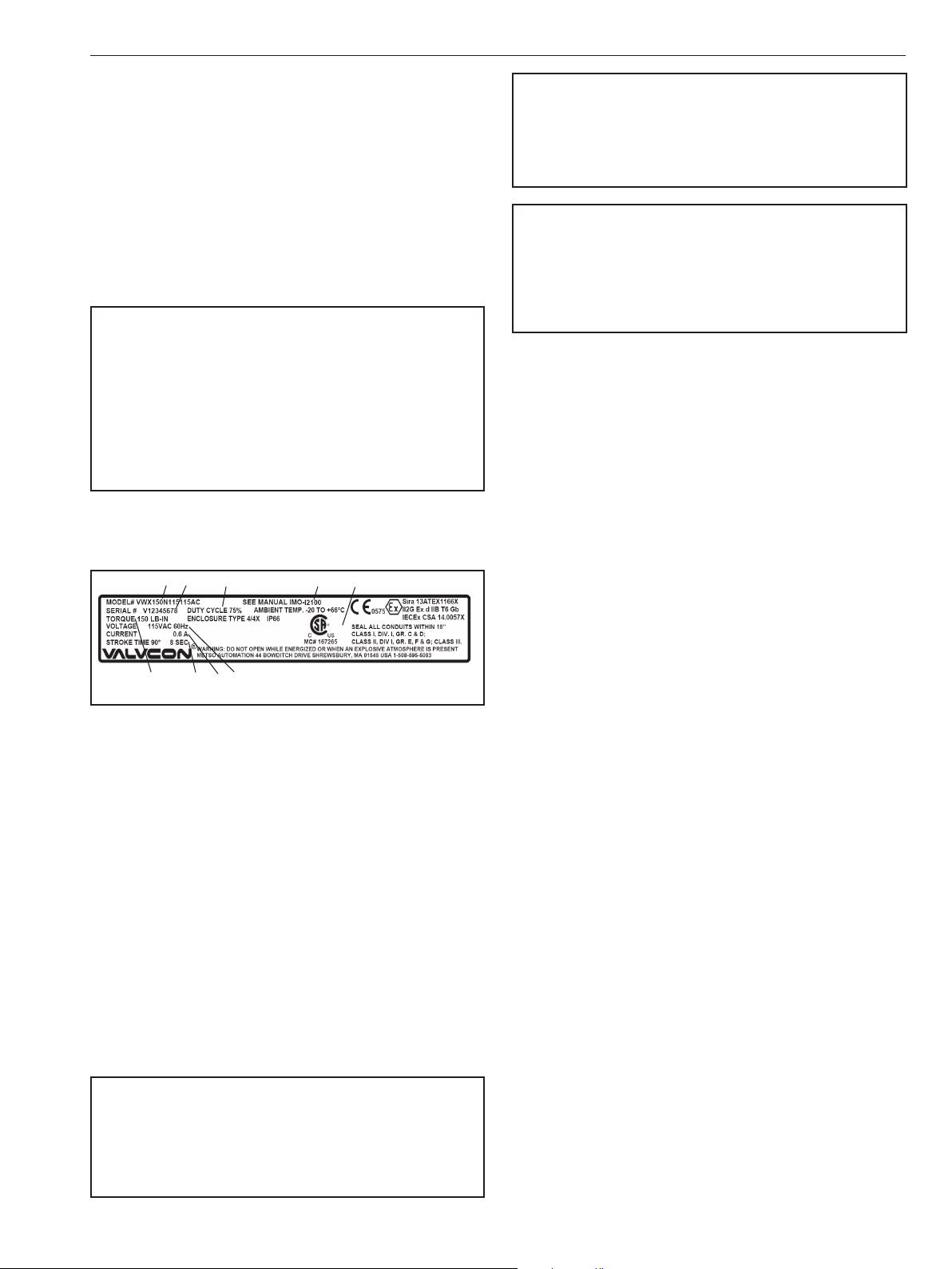
The actuator has an identication label attached to the
base casting (see Figure 1).
WARNING
DO NOT EXCEED THE ACTUATOR ELECTRICAL LIMITATIONS!
EXCEEDING THE ELECTRICAL LIMITATIONS MARKED ON THE
ACTUATOR IDENTIFICATION LABEL MAY CAUSE DAMAGE TO THE
ACTUATOR AND/OR PERSONAL INJURY.
WARNING
BEWARE OF MOVEMENT OF THE FINAL DRIVE ELEMENT AND ANY
LINKAGE BETWEEN IT AND THE ACTUATOR!
KEEP HANDS, OTHER PARTS OF THE BODY, TOOLS AND OTHER
OBJECTS OUT OF THE WAY OF MOVING PARTS. FAILURE TO DO THIS
MAY RESULT IN DAMAGE OR PERSONAL INJURY!
2. TRANSPORTATION AND STORAGE
Check the actuator and any accompanying devices for any
damage that may have occurred during transport.
Store the actuator carefully. Storage indoors in a dry place is
recommended.
Move the actuator to its intended location just before
installation.
Figure 1 Identication Plate
Identication label markings:
1. Model number
2. Serial number
3. Maximum output torque
4. Voltage
5. Current draw (full-load running)
6. Cycle time
7. Duty cycle
8. Applicable manual
9. Certications marking
1.3 Safety Precautions
WARNING
DO NOT EXCEED THE ACTUATOR PERFORMANCE LIMITATIONS!
EXCEEDING THE TORQUE LIMITATIONS MARKED ON THE ACTUATOR
IDENTIFICATION LABEL MAY CAUSE DAMAGE TO THE ACTUATOR
AND/OR FINAL DRIVE ELEMENT.
The actuator is usually shipped in the full clockwise,
(typically closed) position.
If the actuator(s) will be stored for a period longer than 90
days, follow the recommendations in IMO-S2 to maintain
the actuator’s integrity.
3. GENERAL INSTALLATION
INFORMATION
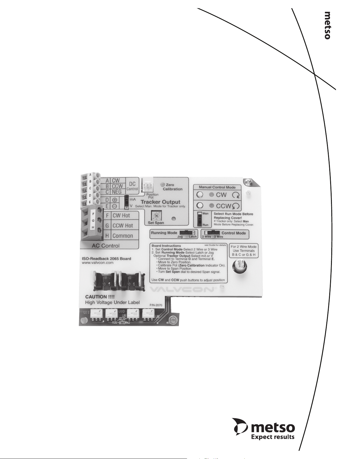
3.1 Description of Iso/Readback Board
The V-Series Iso/Readback Board is a 115/230 VAC option
that provides jogging or latching control from a low voltage
(12 VDC or 24 VDC) or high voltage (115 VAC or 230 VAC)
control signal. It also provides:
• a 4-20 mA or 0-10 DC position “readback” signal
• isolation for the motor, so that multiple actuators may
be wired in parallel
• supervisory control via a mode selector switch and
on-board CW and CCW push buttons. The supervisory
control mode overrides a remote signal for simple and
uninterrupted system set-up.
The isolation feature solves the problem of feedback
voltage interfering with PLC or DCS systems. In standard
electric actuators, the motor acts as an inductive load
and ”steps up” the input voltage, and feeds it back via the
non-powered terminals to the power supply. The Iso/
Readback board isolates the motor from the control signal,
preventing the feedback voltage from reaching the power
supply.
IMO 10/17
4 IMO-I5500 EN
Position indication is available at terminals 5 and 6 on the
Motor Board (for discrete end of travel indication), and at
terminals D and E on the Iso/Readback Board (for analog
position readback).
Note: This option will t all V-Series 115 & 230 VAC actuators
with the letter “N” preceding the voltage designator in the
part number on the product nameplate.
WARNING
DANGEROUS VOLTAGES ARE PRESENT INSIDE THE ACTUATOR
COVER UNLESS THE POWER SUPPLY TO THE ACTUATOR HAS BEEN
SHUT OFF OR DISCONNECTED. USE EXTREME CAUTION WHENEVER
WORKING ON THE ACTUATOR WITH THE COVER REMOVED.
WARNING
ACTUATORS SHOULD BE PROPERLY GROUNDED AND WIRED IN
ACCORDANCE WITH LOCAL ELECTRICAL CODE; SEE NAMEPLATE
FOR MAXIMUM CURRENT DRAW.
3.2 Operation
NOTE: Assumes option is installed; if installing kit, see
Section 3.4 of this manual.
3.2.1 High or Low Voltage Control Signal
The Iso/Readback Board plugs into the Valvcon Motor Board
using standard brackets and mounting screws provided.
Several selector switches are provided on the board for
mode set-up. The matrix below explains the actuator’s
functions for each combination of switch settings:
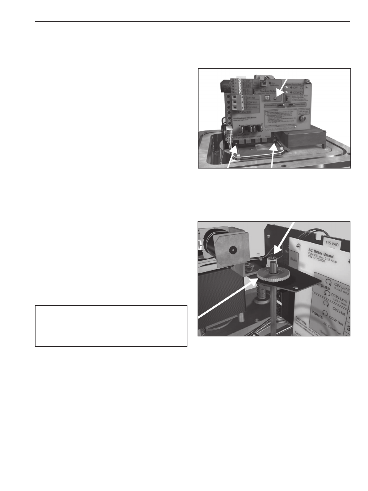
3.2.2 Position Readback
The Iso/Readback Board provides either a 4-20 mA or 0-10
VDC analog signal for position indication. To initiate this
function, connect to terminals D and E on the Iso/Readback
Board. Then:
1. Calibrate the Zero position (4 mA or 0 VDC) by
selecting the “Man” mode and use the on-board CW
push button to drive to the full clockwise position.
Using the 1/16” Allen wrench provided, loosen the
setscrew on the larger, white nylon gear. Adjust that
gear until the “Zero Calibration” LED turns on. Tighten
the setscrew.
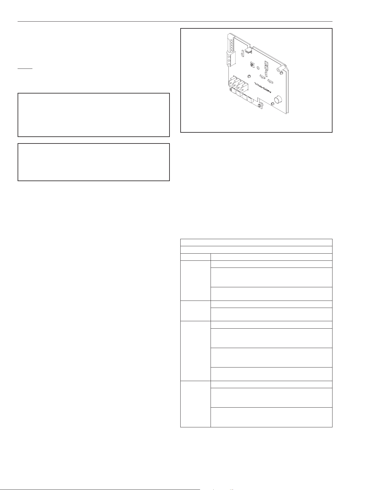
P/N VC002065
Iso/Readback Board
Figure 2
2. Calibrate the Span position by using the on-board
CCW push button to drive to the full counter-clockwise
position. Adjust the “Set Span” potentiometer until
you read the desired Span signal (20 mA or 10 VDC).
3. If you are using the Position Readback signal in
conjunction with a high or low voltage control signal,
return the selector switch to the “Run” mode.
3a. If you are using the Position Readback signal without
the high or low voltage control signal, leave the
selector switch in the “Man” position.
TABLE 1
Selector Switch Modes
Control Running
Jog
When the control signal is maintained at terminals B and
2 Wire
2 Wire
3 Wire
3 Wire
C (DC voltage) or G and H (AC voltage), the actuator will
drive to the full counter-clockwise position
When the control signal is de-energized, the actuator will
drive to the full clockwise position.
Latch
When 2 Wire Mode is selected, the Running Mode must be
set to “Jog”.
Jog
When the control signal is maintained at terminals B and
C (DC voltage) or G and H (AC voltage), the actuator will
drive to the full counter-clockwise position
When the control signal is maintained at terminals A and
C (DC voltage) or F and H (AC voltage), the actuator will
drive to the full clockwise position
When the control signal is de-energized, the actuator will
remain in position.
Latch
When a momentary control signal is applied to terminals
B and C (DC voltage) or G and H (AC voltage), the
actuator will drive to the full counter-clockwise position
When a momentary control signal is applied to terminals
A and C (DC voltage) or F and H (AC voltage), the
actuator will drive to the full clockwise position.
IMO 10/17
IMO-I5500 EN 5
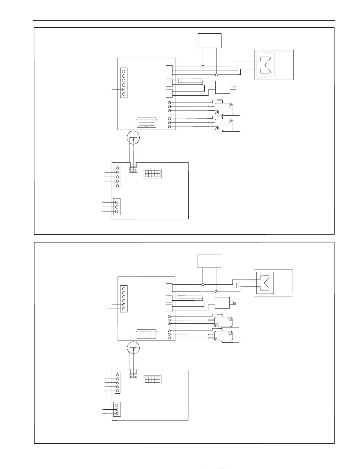
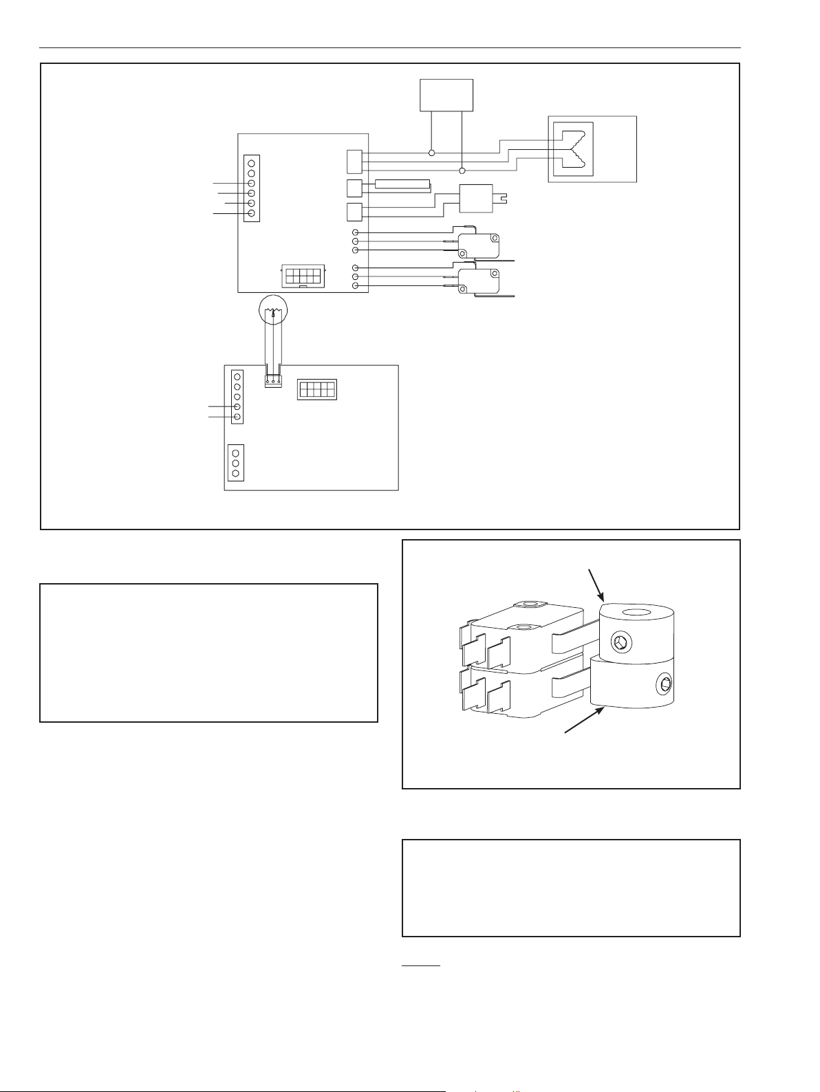
Wiring Diagram – Three Wire Mode
Motor Board
TB1
6
5
Motor
4
L02253
Board
3
2
1
TO OPTION
BOARD
1
2
3
RET. GREEN
SIG. BLACK
+5V RED
TB2
A
B
J1
C
D
G
H
E
F
FROM MOTOR BOARD
Iso/Readback
AC POWER MUST CONNECT
Choose AC or
DC Control
mA or DC
Retransmit
Output is
optional
AC COMMON
AC HOT
DC CONTROL
CW POS
CCW POS
NEG
RETRANSMIT+
OUTPUT –
AC CONTROL
CW HOT
CCW HOT
COMMON
TB1
MOTOR
J2
CONNECTOR
HEATER
J3
OPTION
CONNECTOR
BRAKE
J1
OPTION
CONNECTOR
E10
E11
J4
E12
E13
E14
E15
POSITION FEEDBACK POT.
J3
Board
MOTOR
CAPACITOR
CCW RED
RET BLACK
CW WHITE
HEATER
BROWN
RED
ORANGE
GR AY
VIOLET
BLUE
NO
NC
NO
NC
COM
COM
BRAKE SOLENOID
CLOCKWISE (BOTTOM)
LIMIT SWITCH
COUNTER-CLOCKWISE (UPPER)
LIMIT SWITCH
CAUTION: DOUBLE POLE/NEUTRAL FUSING!
CAUTION: MORE THAN ONE LIVE CIRCUIT!
P/N VC002065 Iso/Readback BOARD
Wiring Diagram – Two Wire Mode
Motor Board
TB1
6
5
L02336
A
B
C
D
E
F
G
H
4
3
2
1
3
+5V RED
TB2
J1
Motor
Board
TO OPTION BOARD
1
2
RET. GREEN
SIG. BLACK
AC POWER MUST
CONNECT
Choose AC or
DC Control
mA or DC
Retransmit
Output is
optional
AC COMMON
AC HOT
DC CONTROL
CCW POS
NEG
RETRANSMIT+
OUTPUT –
AC CONTROL
CCW HOT
COMMON
TB1
MOTOR
CONNECTOR
HEATER
OPTION
CONNECTOR
BRAKE
OPTION
CONNECTOR
J4
POSITION FEEDBACK POT
J3
FROM MOTOR BOARD
Iso/Readback
Board
Figure 3
J2
J3
J1
E10
E11
E12
E13
E14
E15
MOTOR
CAPACITOR
CCW RED
RET BLACK
CW WHITE
HEATER
BROWN
RED
ORANGE
GR AY
VIOLET
BLUE
COM
NO
NC
COM
NO
NC
BRAKE SOLENOID
CLOCKWISE (BOTTOM)
LIMIT SWITCH
COUNTER-CLOCKWISE (UPPER)
LIMIT SWITCH
CAUTION: DOUBLE POLE/NEUTRAL FUSING!
CAUTION: MORE THAN ONE LIVE CIRCUIT!
P/N VC002065 Iso/Readback BOARD
Figure 4
IMO 10/17
6 IMO-I5500 EN
Wiring Diagram – Retransmit Only
Motor Board
TB1
6
Terminal 4 CW Hot (Must Connect)
Terminal 3 CCW Hot (Must Connect)
Terminal 2 AC Common (Must Connect)
Terminal 1 AC Hot (Must Connect)
4-20 mA or 0-10 VDC
Retransmit Output
Terminal D POS (+)
Terminal E NEG (–)
CW HOT
CCW HOT
AC COMMON
AC HOT
RETRANSMIT+
OUTPUT –
5
Motor
4
Board
3
2
1
TO OPTION BOARD
L02337
123
RET. GREEN
SIG. BLACK
+5V RED
TB2
A
B
J1
C
D
E
TB1
F
G
H
FROM MOTOR BOARD
Iso/Readback
MOTOR
J2
CONNECTOR
HEATER
J3
OPTION
CONNECTOR
BRAKE
J1
OPTION
CONNECTOR
E10
J4
E11
E12
E13
E14
E15
POSITION FEEDBACK POT.
J3
Board
MOTOR
CAPACITOR
CCW RED
RET BLACK
CW WHITE
HEATER
BRAKE SOLENOID
BROWN
RED
ORANGE
GR AY
VIOLET
BLUE
COM
NO
NC
NO
NC
COM
CLOCKWISE (BOTTOM)
LIMIT SWITCH
COUNTER-CLOCKWISE (UPPER)
LIMIT SWITCH
CAUTION: DOUBLE POLE/NEUTRAL FUSING!
CAUTION: MORE THAN ONE LIVE CIRCUIT!
P/N VC002065 Iso/Readback BOARD
Figure 5
3.3 Operation for ON/OFF or Jogging
Applications (Motor Board only)
WARNING
VALVCON AC VOLTAGE ACTUATORS USE REVERSING INDUCTION
MOTORS WHICH CAUSE HIGH VOLTAGES. DEVICES CONNECTED
TO TERMINAL 3 AND TO TERMINAL 4 MUST BE RATED FOR
MINIMUM 250 VAC 440 VAC FOR 230 VAC APPLICATIONS. DUE
TO THE INDUCED FEEDBACK VOLTAGE, MULTIPLE ACTUATORS
CANNOT BE WIRED IN PARALLEL. SEPARATE ISOLATED CONTACTS
MUST BE PROVIDED FOR EACH ACTUATOR.
3.3.1 Set Up for Operation
Two limit switches operated by the cams on the output shaft
determine the exact positions where the actuator will stop
at each end of travel. The bottom limit switch determines
the clockwise stop position. The next limit switch up
from the bottom determines the counter-clockwise stop
position. The end of travel limit switches can be adjusted to
provide from 5 to 320 degrees of actuator rotation.
The two standard limit switches may be used to indicate
the open and closed status of the actuator. Terminals 5
(counter-clockwise) and 6 (clockwise) provide the position
indication at line voltage. If dry contacts or intermediate
position indication are needed, additional limit switches
and cams may be installed in the actuator. When additional
limit switches are installed, they can be set in any position
and are wired to a separate terminal block provided with
the option. See (Section 4), V-Series Standard Options.
Counter-Clockwise (CCW) CAM and SWITCH
Clockwise (CW) CAM and SWITCH
Figure 6
3.3.2 Setting Actuator Stop Positions
WARNING
DANGEROUS VOLTAGES ARE PRESENT INSIDE THE ACTUATOR
COVER UNLESS THE POWER SUPPLY TO THE ACTUATOR HAS BEEN
SHUT OFF OR DISCONNECTED. USE EXTREME CAUTION WHENEVER
WORKING ON THE ACTUATOR WITH THE COVER REMOVED.
NOTE: To gain more access to cams, move the capacitor
and terminal strip, if installed.
1. Loosen the set screw in the cam using a 1/16” hex
wrench. The bottom cam controls the clockwise end-of-
IMO 10/17
IMO-I5500 EN 7
travel, and the second cam, (from the bottom) controls
the counter-clockwise end-of-tavel (See Figure 3).
2. Move the actuator to the desired STOP position
3. Apply power according to desired mode of operation
or use the manual override. (See Figures 4, 5 & 6)
4. Remove the power and rotate cam in the direction of
travel to the exact point the switch “clicks” closed.
5. Tighten the set screw.
6. Repeat this procedure to set the opposite end of the
travel limit.
3.3.3 Proper Actuator Cover Installation
1. Remove the override shaft from the actuator cover
bushing; if the actuator is equipped with a handwheel,
remove the handwheel before removing the top piece
of the “two-piece” shaft form the cover bushing.
2. Install the override shaft on the square motor shaft; if
the actuator is equipped with a handwheel, install the
bottom piece of the “two-piece” shaft on the motor
shaft and then install the top piece of the shaft onto
the bottom piece of the shaft.
3. Align cover so that the override shaft will pass through
the override bushing and carefully push it down so
that the cover ange contacts the base ange.
3. Plug Pot connector into the 3-pin connector on the front
of the Iso/Readback Board (“J1”). Plug Iso/Readback
Board into Motor Board (P/N VC002015) via 10-pin
connector and secure to the existing bracket with
three mounting screws. (See Figure 7).
Figure 7
4. Place small (20-tooth) gear on Pot shaft and tighten.
Place spacer on Camshaft then place large (60-tooth)
gear on Camshaft. Properly positioned, gears should
mesh evenly. (See Figure 8).
4. Once the cover is properly seated, tighten the screws
to secure the cover; a cross pattern is recommended
for uniform distribution of load.
5. If the position indicator is not seated to the output/
cam shaft, turn until it drops into place in order to
ensure accurate visual position indication.
3.4 Board Installation
WARNING
DANGEROUS VOLTAGES ARE PRESENT INSIDE THE ACTUATOR
COVER UNLESS THE POWER SUPPLY TO THE ACTUATOR HAS BEEN
SHUT OFF OR DISCONNECTED. USE EXTREME CAUTION WHENEVER
WORKING ON THE ACTUATOR WITH THE COVER REMOVED.
3.4.1 Tools Required
• 1/16” Hex wrench
• #1 or #0 Philips Screwdriver
• 1/2” Wrench/Nut driver
3.4.2 Installation Instructions
!Disconnect Power!
1. Remove and discard screw that secures Motor Board
to the upper bracket. (See Figure 9).
2. Remove 1/2” nut and lockwasher from potentiometer
(Pot) shaft and insert, “Pot shaft up” through hole in
upper support bracket. Align lockwasher and nut and
tighten.
Figure 8
5. Loosen setscrew in CW or CCW cam. (1/16 hex wrench)
CW = bottom cam
CCW = next cam up from bottom cam
6. Connect AC Power to terminal 1 (Hot) and 2 (Common)
of Motor Board P/N VC002015. Select Manual Mode
and drive to desired STOP position. Remove power.
7. Rotate cam in the direction of travel to the exact point
that the switch “clicks” open. Tighten setscrew
8. Repeat procedure 5, 6 and 7 to set opposite end of
travel limit.
9. Connect AC or DC Control Signals to AC or DC Control
terminals to achieve desired operation, as indicated in
wiring diagrams on previous pages.
IMO 10/17

8 IMO-I5500 EN
Exploded View
DC Control Signal
Terminals - A, B & C
AC Control Signal
Terminals - F, G & H
P/N VC002065
Board
Selector Switch for
Jogging or Latching
Mode
Mounting Screw
Optional Retransmit
Terminals - Connect D&E
Locations
1 (AC Hot), 2 (Neutral)
Pot Connector
Selector Switch for
Manual or Run Mode
Optional Locking
Brake Assembly
Motor Board
Terminals 1 & 2
To install P/N VC002065
board, discard this screw
10 Pin
Connector
Selector Switch for 2
Wire or 3 Wire Mode
Figure 9
4. VSERIES STANDARD OPTIONS
All V-Series options are designed to be easily installed in the
eld. Options for all standard V-Series actuators are universal
and completely interchangeable with each enclosure size.
For additional V-Series Options, see (Table3). Voltage is not
eld changeable.
4.1 Option “H” – Tropical Heater and
Thermostat P/N VC099716, VC099723
The tropical heater and thermostat option is a self-adhesive,
resistance heater strip which is applied to the primary
gearbox. It installs with a plug-in connector and is
recommended in high-humidity applications. The tropical
heater option is also recommended in installations that
experience wide temperature swings in order to evaporate
any condensation. Thermostat is pre-set to activate at or
below 90˚F (32˚C) and deactivate at or above 110˚F (43˚C).
The tropical heater draws 15 watts at 115 VAC; 40 watts at
230 VAC (see IMO-I9500 for additional reference).
WARNING
WHENEVER WORKING INSIDE THE ACTUATOR BE SURE TO FOLLOW
ALL GUIDELINES, AND HEED ALL WARNINGS IN THIS MANUAL. IF
INSTALLING AN OPTION KIT, BE SURE TO READ AND FOLLOW THE
SUPPLIED INSTRUCTIONS CAREFULLY AND HEED ANY ADDITIONAL
WARNINGS.
Option “H” Tropical Heater and Thermostat
Option “T” Standard Heater and Thermostat
Figure 10
4.2 Option “I” – ISO 5211 Output
150 – 600 lb•in (12 - 25 lb•ft; 17 - 68 Nm) models are
supplied with a 3/4” female square output coupling; when
the “I” option is selected they are supplied with a 14 mm
female square.
1000 – 3000 lb•in (83 - 250 lb•ft; 113 - 339 Nm) models are
supplied with a 1” female square output coupling; when the
“I” option is selected, 1000 lb•in (83 lb•ft; 113 Nm) models
are supplied with a 19 mm female square and 1500 – 3000
lb•in (125 - 250 lb•ft; 169 - 339 Nm) models are supplied
with a 22 mm female square.
This option can be installed in the eld; for 115 VAC
applications, order kit P/N VC099716 and for 230 VAC
applications, order kit P/N VC099723.
IMO 10/17
This option is factory installed only.
IMO-I5500 EN 9
4.3 Option “K” – Mechanical Brake
P/NVC099715
The brake option prevents back-driving; it is required
on all buttery valve and damper applications. It is also
recommended on PVC ball valves and resilient seated
valves. The brake option draws 4 watts and is universal to
all standard V-Series actuators. It is simple to install with a
plug-in connector and two philips head mounting screws.
No additional brackets are required (see IMO-I9715 for
additional reference).
WARNING
WHENEVER WORKING INSIDE THE ACTUATOR BE SURE TO FOLLOW
ALL GUIDELINES, AND HEED ALL WARNINGS IN THIS MANUAL. IF
INSTALLING AN OPTION KIT, BE SURE TO READ AND FOLLOW THE
SUPPLIED INSTRUCTIONS CAREFULLY AND HEED ANY ADDITIONAL
WARNINGS.
This option can be installed in the eld; order kit P/N
VC099715.
Option “K” – Mechanical Brake
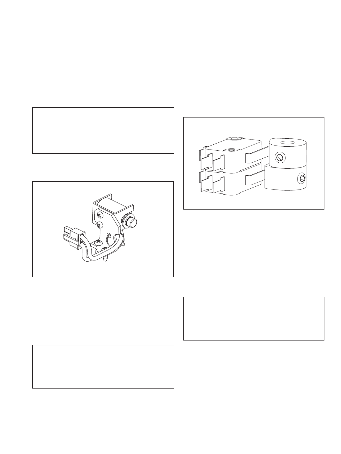
4.5 Option “S2” – Two Auxiliary Limit
Switches P/N VC099000
The extra switches and stainless steel cams provide dry
contacts and are fully adjustable to trip at any position. They
are often used for position indication or to interlock other
devices (such as in sequencing operations). The switches
are single pole, double throw switches rated for 11A 1/2HP
250 VAC, CSA certied. Auxiliary switch kit P/N VC099000
is universal to all standard V-Series actuators and includes
“ying wiring leads” for termination inside of the actuator
enclosure using the supplied 6 position terminal block (see
IMO-I9000 for additonal reference).
Option “S2” – Two Auxiliary Limit Switches
Figure 11
4.4 Option “P” – Feedback Potentiometer
P/N VC099200
The Feedback Potentiometer option provides 0 – 1000 Ohm
resistance feedback and includes a 12 position terminal
block for internal wiring (see IMO-I9200 for additional
reference).
WARNING
WHENEVER WORKING INSIDE THE ACTUATOR BE SURE TO FOLLOW
ALL GUIDELINES, AND HEED ALL WARNINGS IN THIS MANUAL. IF
INSTALLING AN OPTION KIT, BE SURE TO READ AND FOLLOW THE
SUPPLIED INSTRUCTIONS CAREFULLY AND HEED ANY ADDITIONAL
WARNINGS.
Figure 12
4.6 Option “T” – Heater and Thermostat
P/N VC099515, P/N VC099523
The heater and thermostat option is a self-adhesive,
resistance heater strip which is applied to the primary
gearbox. It installs with a plug-in connector and is
recommended in installations where the ambient
temperatures drop below 32˚F (0˚C). Thermostat is pre-set
to activate at or below 40˚F (4˚C) and deactivate at or above
60˚F (15˚C). The heater draws 15 watts at 115 VAC; 40 watts
at 230 VAC (see IMO-I9500 for additional reference).
WARNING
WHENEVER WORKING INSIDE THE ACTUATOR BE SURE TO FOLLOW
ALL GUIDELINES, AND HEED ALL WARNINGS IN THIS MANUAL. IF
INSTALLING AN OPTION KIT, BE SURE TO READ AND FOLLOW THE
SUPPLIED INSTRUCTIONS CAREFULLY AND HEED ANY ADDITIONAL
WARNINGS.
This option can be installed in the eld; for 115 VAC
applications, order kit P/N VC099515 and for 230 VAC
applications, order kit P/N VC099523. (see Figure 10)
This option can be installed in the eld; order kit P/N
VC099000.
IMO 10/17

10 IMO-I5500 EN
4.7 Option “Y” - Keyed Output
150 – 600 lb•in (12 - 25 lb•ft; 17 - 68 Nm) actuators are
supplied with a 3/4” female square output coupling; when
the “Y” option is selected they are supplied with a 15mm
female keyed output.
1000 – 3000 lb•in (83 - 250 lb•ft; 113 - 339 Nm) models are
supplied with a 1” female square output coupling; when the
“Y” option is selected they are supplied with a 20mm female
keyed output.
This option is factory installed only.
4.8 Option “Z” – Handwheel Override
P/N VC009097, P/N VC009098
All V-Series actuators are supplied with a wrench-operated
manual override shaft. If the Handwheel Override option is
selected the shaft is replaced by a declucthable shaft and a
six-inch handwheel (see IMO-I9090 for additional reference).
WARNING
WHENEVER WORKING INSIDE THE ACTUATOR BE SURE TO FOLLOW
ALL GUIDELINES, AND HEED ALL WARNINGS IN THIS MANUAL. IF
INSTALLING AN OPTION KIT, BE SURE TO READ AND FOLLOW THE
SUPPLIED INSTRUCTIONS CAREFULLY AND HEED ANY ADDITIONAL
WARNINGS.
This option can also be installed in the eld; for 150 –
600 lb•in (12 - 25 lb•ft; 17 - 68 Nm) models order kit P/N
VC009097 and for 1000 – 3000 lb•in (83 - 250 lb•ft; 113 - 339
Nm) models order kit P/N VC009098.
4.9 Voltage
5.2 Wiring
WARNING
VALVCON AC VOLTAGE ACTUATORS USE REVERSING INDUCTION
MOTORS WHICH CAUSE HIGH VOLTAGES. DEVICES CONNECTED
TO TERMINAL 3 AND TO TERMINAL 4 MUST BE RATED FOR
MINIMUM 250 VAC 440 VAC FOR 230 VAC APPLICATIONS.
CONTROLLERS WITH SOLID STATE OUTPUTS MUST BE RATED
FOR MORE THAN 250 VAC. WE STRONGLY RECOMMEND THAT
RELAY OUTPUTS BE USED ON CONNECTED DEVICES. DUE TO THE
INDUCTION FEEDBACK VOLTAGE, MULTIPLE ACTUATORS CAN NOT
BE WIRED IN PARALLEL. SEPARATE ISOLATED CONTACTS MUST BE
PROVIDED FOR EACH ACTUATOR. IF THE ACTUATOR IS DRIVEN BY
CONTACTS ON A PC OR PLC, MAKE SURE THE CONTACTS HAVE THE
PROPER RATINGS.
5.3 Duty Cycle and Motor Protection
V-Series actuators can operate continuously for up to 15
minutes at 104˚F (40˚C). After 15 minutes of continuous
operation they are rated for 75% duty cycle operation at
104˚F and for 30 starts per minute. Duty cycles decrease at
temperatures in excess of 104˚F. Duty cycle is the maximum
proportion of “on” time and the minimum required “o” time
to prevent thermal overloading. Actuators with cycle times
of 30 seconds must rest at least 10 seconds between cycles.
Higher temperature applications decrease duty cycle.
AC motors contain thermal overload protection. Exceeding
the rated duty cycle may cause the thermal overload switch
to temporarily remove power to the motor and cause it to
stall. After the motor cools, the actuator will resume normal
operation. The thermal protector is a safety device, designed
for infrequent use. Constant tripping of the thermal overload
protector may cause premature motor failure.
115 VAC or 230 VAC. V-Series actuators are rated for full
torque at +/- 10% of the nominal voltage at 60 Hz. Note:
operation at 50 Hz will proportionally decrease the duty
cycle and increase the cycle time. V-Series actuators are
rated for a minimum of 75%* duty cycle at 60 Hz at 104˚F
(40˚C).
* 55% duty cycle for 3000 lb•in actuators.
5. GENERAL OPERATING INFORMATION
For enclosure specications and dimensions, see (Tables
1-2 and Figure 13).
5.1 Enclosure Ratings and Product
Certications
Metso oers two versions of V-Series actuator enclosures:
the “W” enclosure is weathertight, and the “WX” enclosure
which is weathertight and explosion-proof.
IMO 10/17
5.4 Operating Temperature Limits
V-Series actuators are designed to operate in ambient
environments between -40˚F (-40˚C) and 150˚F (65˚C). In
outdoor applications where ambient temperatures exceed
80˚F, actuators should be shielded from direct sunlight.
In applications with high media temperatures, insulating
blankets, heat shields and/or extended mounting shafts
should be used to maintain ambient temperatures at the
actuator within normal operating limits.
Heaters and thermostats are recommended for all outdoor
applications and may also be used to dry condensation in
high humidity environments.
5.5 Actuator Mounting
The actuator may be mounted in any position including
upside-down. It must be rmly secured to a direct mount
ange or sturdy mounting bracket. A minimum of four bolts
with lock washers should be used to secure the actuator to the
bracket. Flexibility in the bracket is not allowed, and backlash,

IMO-I5500 EN 11
or “play”, in the coupling should be minimized. The actuator
output shaft must be in line (centered) with the valve shaft to
avoid side-loading the shaft. See (Figure 13) for output drive
dimensions and mounting hardware specications.
WARNING
FAILURE TO USE MANUAL OVERRIDE PROPERLY COULD RESULT
IN DAMAGE TO THE ACTUATOR GEARING. ENSURE THAT THE
OVERRIDE IS FULLY DISENGAGED AND DO NOT USE EXCESSIVE
FORCE WHEN MANUALLY POSITIONING ACTUATOR. DO NOT DRIVE
THE ACTUATOR BEYOND THE TRAVEL LIMIT SETTINGS. FAILURE TO
FOLLOW THESE INSTRUCTIONS COULD RESULT IN DAMAGE TO THE
ACTUATOR AND/OR FINAL DRIVE ELEMENT.
5.6 Manual Override
To use the manual override, push the override shaft down
approximately 1/4 inch to disengage the motor from the
gear train. Failure to disengage motor prior to turning
override will cause damage to the actuator. While holding
the shaft down, turn the shaft with a wrench or handle to
the desired position. NOTE: The override shaft on actuators
below 1000 lb•in must be rotated in the opposite direction
of the desired direction of the output shaft. In actuators
1000 lb•in and above, the override and the output shaft
turn in the same direction.
Do not drive the actuator beyond the limit switch settings;
it is possible to damage installed options such as a feedback
potentiometer. The manual override shaft must be returned
to its fully upward position before the motor is re-engaged.
Rotate the shaft slightly to align the spur gears until the
shaft “springs” back to its re-engaged position. NOTE: The
rotation direction of the output may not be the same as the
rotation of the override shaft!
5.9 Warranty
All V-Series actuators are backed by a 2-year warranty that
covers materials and workmanship. The warranty expires
24 months from installation or 30 months from delivery;
whichever comes rst.
To request a Return Authorization for an actuator within the
warranty period, please consult your local Metso distributor.
5.10 Repair Service/Spare Parts
We recommend that electric actuators be directed to our
Northeast Service Center for maintenance. The Service
Center is equipped to provide rapid turn-around at
reasonable cost and oer new product warranty with all
reconditioned electric actuators.
For electric actuators outside of the warranty period,
request a Return Authorization by calling the Northeast
Service Center at (508) 595-5195; or by sending an e-mail to
valvconservice@metso.com.
NOTE: When sending electric actuators to the Service
Center for repair, do not disassemble them! The actuator
should be relatively clean upon return. For further
information on spare parts and service or assistance, visit
our Web site at www.metso.com/electricactuators.
NOTE: When ordering spare parts, always include the
following information:
a. Actuator model number from the product nameplate.
b. Serial number from the product nameplate.
5.7 Lubrication
All rotating power train components are permanently
lubricated with multi-purpose Lithium grease suitable for
the operating temperature range of the actuator. Additional
lubrication is not required in normal operation.
5.8 Problem Prevention
Most actuator problems result from improper installation.
• Incorrect Wiring and Set Up Make certain the actuator is
wired correctly and travel stops are properly set before
power is applied.
• Coupling, Alignment, and Mounting Do not add extra
torque! Make certain that the mounting arrangement is
sturdy, centered, properly aligned, and that all mounting
hardware is secure and properly tightened.
• Moisture Replace the cover tightly and make certain
conduit entry holes are sealed properly to prevent
moisture inltration.
c. Part number and/or description of the part required.
d. Required quantity.
IMO 10/17

12 IMO-I5500 EN
6. SPECIFICATIONS & TECHNICAL INFORMATION
Table 1 - Torque & VA Ratings
Torque
Output at
breakaway
150 lb•in;
12 lb•ft; 17 Nm
300 lb•in;
25 lb•ft; 34 Nm
600 lb•in
50 lb•ft; 68 Nm
1000 lb•in
83 lb•ft; 113 Nm
1500 lb•in
125 lb•ft; 169 Nm
2000 lb•in
167 lb•ft; 226 Nm
2500 lb•in
208 lb•ft; 282 Nm
3000 lb•in
250 lb•ft; 339 Nm
Temperature Range -40°F to 150°F (-40°C to 65°C)
Conduit Connections
Output
Duty Cycle
Voltage
Limit Switches
Motor Split phase, capacitor driven motor with Class B or better insulation; sub-fractional horsepower
Lubrication Permanently lubricated gear train and bearings
Gear Train Hardened steel spur gears
Approximate Weight
Enclosure Die cast aluminum
Speed
(seconds
per 90˚
rotation)
8 75% 70 vA 115 vA 0.6 amps 0.5 amps 1.25 amps 0.924 amps
15 75% 70 vA 115 vA 0.6 amps 0.5 amps 1.25 amps 0.924 amps
30 75% 70 vA 115 vA 0.6 amps 0.5 amps 1.25 amps 0.924 amps
25 75% 92 vA 161 vA 0.8 amps 0.7 amps 1.66 amps 1.29 amps
40 75% 92 vA 161 vA 0.8 amps 0.7 amps 1.66 amps 1.29 amps
55 75% 92 vA 161 vA 0.8 amps 0.7 amps 1.66 amps 1.29 amps
70 75% 92 vA 161 vA 0.8 amps 0.7 amps 1.66 amps 1.29 amps
75 55% 92 vA 161 vA 0.8 amps 0.7 amps 1.66 amps 1.29 amps
Duty
Cycle
VA Rating
115 VAC 230 VAC 115VAC 230 VAC 115 VAC 230 VAC
Max Running
Current at Full Load
(True MS)
Max Eective Peak
Inrush Current (= .66 x)
Peak rush
Table 2 - Specications
(2) 3/4” NPT in sizes up to 600 lb•in (3/4” to 1/2” reducing bushings included)
(2) 3/4” NPT in sizes 1000 lb•in and above (3/4” to 1/2” reducing bushings included)
150 to 600 lb•in (12 - 25 lb•ft; 17 - 68 Nm) ISO 5211 F05 and F07 bolt circles, 3/4” female square (14mm female square w/ “I”
Option; 15mm female keyed output w/ “Y” Option).
1000 to 3000 lb•in (83 - 250 lb•ft; 113 - 339 Nm): ISO 5211 F07 and F10 bolt circles, 1” female square (1000 lb•in (83 lb•ft; 113
Nm): 19mm female square w/ “I” Option; 1500 - 3000 lb•in (125 - 250 lb•ft; 169 - 339 Nm) : 22mm female square w/ “I” Option;
1000 to 3000 lb•in (83 - 250 lb•ft; 113 - 339 Nm): 20mm female keyed output w/ “Y” Option)
The actuator may run continuously at temperatures below 104° F for up to 15 minutes. After that 15 minutes, the actuators
may run up to 75% duty cycle (between each full cycle), the actuator must rest for 1/3 of the 90 degree cycle time. NOTE: At
50 Hz, the duty cycle is ~60% at 104° F (40°C).
115 VAC: 103.5 to 126.5 VAC, 60 Hz
230 VAC: 207 to 253 VAC, 60 Hz
(2) Single pole, double throw switches rated for 11A 1/2HP 250 VAC, CSA certied, fuse protected.
Two standard switches are used for end of travel control, and for pilot or position indication at terminal 5 and terminal 6.
Indication outputs are protected by 0.25 AMP permanent auto reset polyfuses – reset time approximately 3 mins.
17 lbs (8 kg) for sizes up to 600 lb•in (50 lb•ft; 68 Nm)
31 lbs (14 kg) for sizes 1000 lb•in (83 lb•ft; 113 Nm) and above
IMO 10/17

3/4 NPT Standard
1/2 NPT with Bushing
6.000
6.1
3.1
4.1
5.8
1.7
*12.8
11.1
10.3
Optional
Handwheel
Shown
10.8
9.8
7.5
4.6
3.3
Female Square Drive
Mounting Flange, ISO 5211
All Dimensions in inches unless otherwise
0.787 (20mm)
TO REMOVE COVER REQUIRES AN ADDITIONAL 5.75"
LV-SERIES ENCLOSURES
1.50 (38.1mm)
stated
LV-Series
*11.7 WITHOUT HANDWHEEL
F07/F10
Female Keyed Drive
Actuator SizeDrive Option Drive Type Drive Size Depth
1000-3000 lb-inStandardSquare1.000 (25mm) 1.20 (30.5mm)
1000 lb-in Option "I" Square 0.748 (19mm) 1.20 (30.5mm)
1500-3000 lb-in Option "I" Square 0.866 (22mm) 1.20 (30.5mm)
1000-3000 lb-in Option "Y" Keyed
Approximate Weight 31 lb
4.6
0.75" MIN.
ON
4 X M8-1.25
2.756" B. C. ON
4 X M10-1.5
0.75" MIN.
SEE TABLE
20 mm
22.4 mm
4.8 mm
4.016" B. C.
IMO-I5500 EN 13
6.1 Dimensions
LVSERIES
Actuator Size Drive Option Drive Type Drive Size Depth
1000-3000 lb-in (83-250 lb-ft; 113-339 Nm) Standard Square 1.000 (25mm) 1.20 (30.5mm)
1000 lb-in (83 lb-ft; 113 Nm) Option “I” Square 0.748 (19mm) 1.20 (30.5mm)
1500-3000 lb-in (125-250 lb-ft; 169-339 Nm) Option “I” Square 0.866 (22mm) 1.20 (30.5mm)
1000-3000 lb-in (83-250 lb-ft; 113-339 Nm) Option ”Y” Keyed 0.787 (20mm) 1.50 (38.1mm)
VSERIES
Approximate Weight 31 lb / 14 kg
150-600 lb-in (12-50 lb-ft; 17-68 Nm) Standard Square 0.750 (19mm) 0.90 (22.9mm)
150-600 lb-in (12-50 lb-ft; 17-68 Nm) Option “I” Square 0.551 (14mm) 0.90 (22.9mm)
150-600 lb-in (12-50 lb-ft; 17-68 Nm) Option ”Y” Keyed 0.591 (15mm) 1.40 (35.6mm)
Actuator Size Drive Option Drive Type Drive Size Depth
V-Series
Figure 13
Approximate Weight 17 lb / 8 kg
IMO 10/17

14 IMO-I5500 EN
V-Series spare Parts List
6.2 Exploded View
Optional
Brake Kit
Optional
Feedback Pot Kit
Optional Extra Switch Kit
Optional
Heater Kit
Item No. Part No. Description
1 N/A Cover
Cover screw
VCK00012 Small enclosure
2 (150 – 600 lb•in)
VCK00013 Large enclosure (1000 – 3000 lb•in)
Potentiometer/Cam Shaft Gears
3 VC099090 90 degree Operation
VC099180 180 degree Operation
VC099270 270 degree Operation
Override shaft (replacement only)
4 VC091244 Small enclosure (150 – 600 lb•in)
VC093023 Large enclosure (1000 – 3000 lb•in)
Motor Gearbox
VC090101 115 VAC, 150 – 300 lb•in
VC090102 115 VAC, 600 lb•in
5 VC090201 115 VAC, 1000 – 3000 lb•in
VC090103 230 VAC, 150 – 300 lb•in
VC090104 230 VAC, 600 lb•in
VC090202 230 VAC, 1000 – 3000 lb•in
6 VC001020 Limit Switch
7 VC091352 Cam with set screw
Capacitor
VC093041 115 VAC, 150 – 600 lb•in
8 VC093061 115 VAC, 1000 – 3000 lb•in
VC093051 230 VAC, 150 – 600 lb•in
VC093071 230 VAC, 1000 – 3000 lb•in
Bracket, mounting, motor board w/screws
9 VC091695 Small enclosure (150 – 600 lb•in)
VC091698 Large enclosure (1000 – 3000 lb•in)
Bracket, motor board, upper
10 VC091684 Small enclosure (150 – 600 lb•in)
VC091688 Large enclosure (1000 – 3000 lb•in)
Motor board with screws
VC092015 115 VAC
VC092030 230 VAC
IMO 10/17
Motor Board
Optional
Control Board
Shown
V-Series option kits
Item No. Part No. Description
VC099715 Brake (ALL)
VC099200 Feedback pot (ALL)
VC099000 Extra limit switch (ALL)
VC099515 Heater Thermostat 115 VAC (ALL)
VC099523 Heater Thermostat 230 VAC (ALL)
VC099642 Control Board (ALL)
VC092065 Iso/Readback Board
Hand-wheel Override
VC009097 Small enclosure (150 – 600 lb•in)
VC009098 Large enclosure (1000 – 3000 lb•in)
VC099716 Tropical Heater/Thermostat 115 VAC
VC099723 Tropical Heater/Thermostat 230 VAC
Figure 14
IMO-I5500 EN 15
7. VSERIES ACTUATORS BY MODEL NUMBER
Table 3
Standard V/LV-Series Actuators (with “N” in model number before the voltage code)
Series Enclosure Type Torque Board Options
Code Description Cod e Description Co de Description Code Description Code Description
V W Weathertight 150 150 lb•in; C Control Board H2Tropical Heater/Thermostat N115AC 115 VAC
NEMA 4/4X 12 lb•ft; 17 Nm J Speed Control/Timer Board I3aISO 5211 Output N230AC 230 VAC
300 300 lb•in; U Iso/Readback Board K Brake
WX Weathertight & Explosionproof 25 lb•ft; 34 Nm P Feedback Potentiometer
NEMA 4/4X/7&9 600 600 lb•in; S2 Two Auxiliar y Limit Switches
50 lb•ft; 68 Nm T4Heater/Thermostat
LV W Weathertight 1000 1000 lb•in C Control Board H2Tropical Heater/Thermostat N115AC 115 VAC
NEMA 4/4X 83 lb•ft; 113 Nm J Speed Control/Timer Board I3bISO 5211 Output N230AC 230 VAC
1500 1500 lb•in U Iso/Readback Board K Brake
WX Weathertight & Explosionproof 125 lb-ft; 169 Nm P Feedback Potentiometer
NEMA 4/4X/7&9 2000 2000 lb•in S2 Two Auxiliary Limit Switches
167 lb-ft; 226 Nm T4Heater/Thermostat
2500 2500 lb•in Y5bKeyed Output
208 lb-ft; 282 Nm Z Handwheel
3000 3000 lb•in
250 lb-ft; 339 Nm
Notes: 1. Select only one board option, as needed.
2. This heater option activates at or below 90˚F and deactivates at 110˚F; it is recommended in high-humidity applications.
3a. 150 – 600 lb•in (12 - 25 lb•ft; 17 - 68 Nm) models with “I” option are supplied with a 14 mm female square (note that without option “I”
the female square is 3/4”)
3b. 1000 lb•in (83 lb•ft; 113 Nm) models with “I” option are supplied with a 19 mm female square and 1500 – 3000 lb•in (125 - 250 lb•ft;
169 - 339 Nm) models are supplied with a 22 mm female square (note that without option “I” the female square is 1”)
4. This heater option activates at or below 40˚F and deactivates at 60˚F; it is recommended in applications where the temperature may
drop below 32˚F.
5a. 150 - 600 lb•in (12 - 25 lb•ft; 17 - 68 Nm) models with “Y” option are supplied with a 15mm female keyed output.
5b. 1000 - 3000 lb•in (83 - 250 lb•ft; 113 - 339 Nm) models with “Y” option are supplied with a 20mm female keyed output.
1
Other Options Operating Voltage
Y5aKeyed Output
Z Handwheel
For enclosure specications and dimensions see (Tables1-2
and Figure 13).
• Enclosure “W” (weathertight) is certied by CSA
to meet specications for NEMA 4/4X; IP 66 for
weathertight and dust-tight, environments and is CE
compliant. It is intended for non-hazardous locations;
indoor or outdoor use.
• Enclosure “WX” (weathertight & explosionproof) is
certied by CSA to meet specications for NEMA 7&9,
hazardous locations, (Class I, Division 1, Groups C, and
D; Class II, Division 1, Groups E, F, and G; Class III) as well
as to meet NEMA 4/4X and IP 66 specications. The
enclosure is CE compliant, certied to ATEX directive
94/9/EC: Ex d IIB T6 Gb, and IECEx CSA 14.0057X.
Sample Model Code: LVW1500CHIKS2N230AC
Actuator Series LV
Enclosure Type W
Torque 1500
Board Option C
Other Options (if applicable) H
I
K
S2
Operating Voltage N230AC
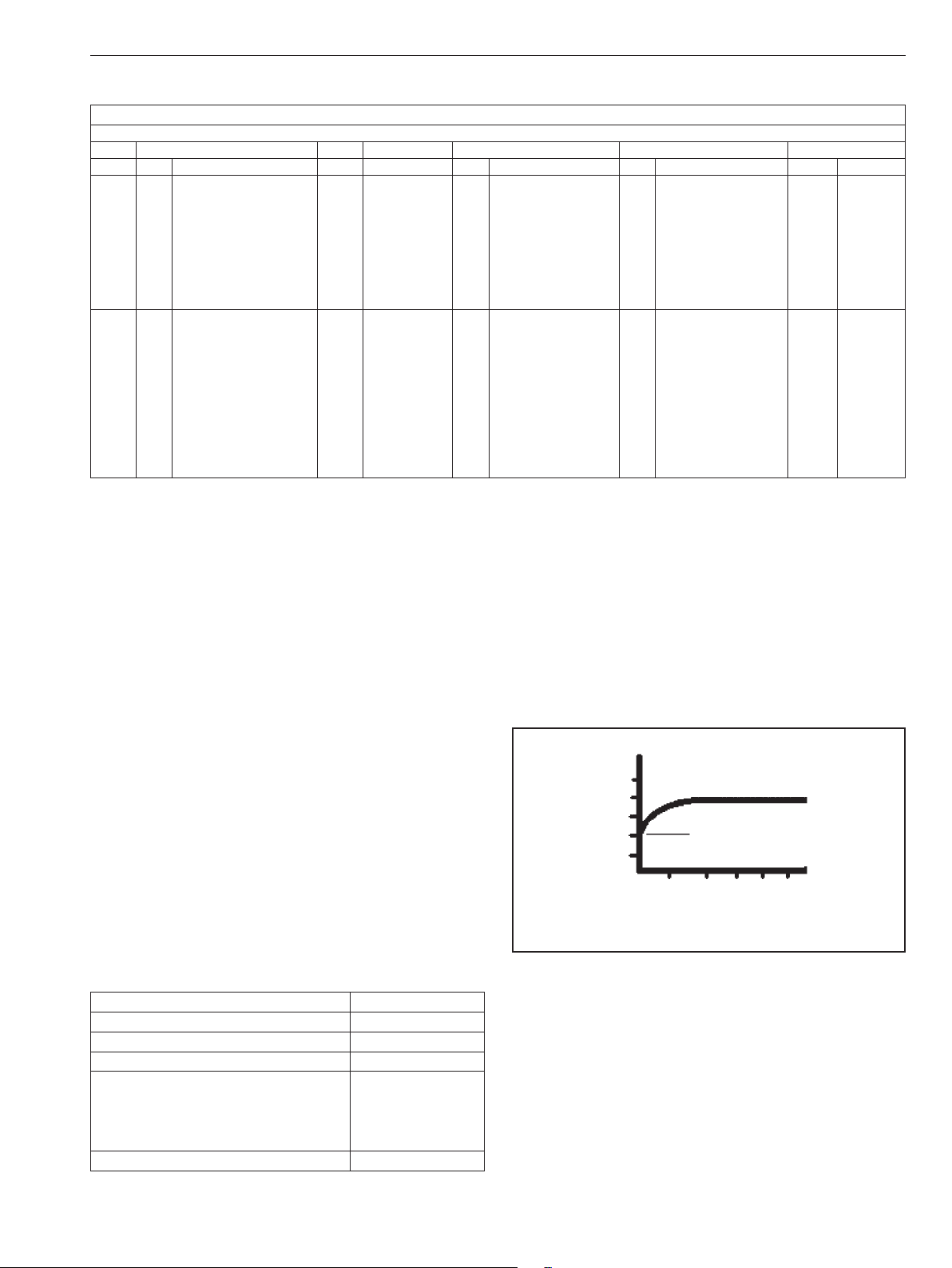
• Torque = Breakaway Torque Valvcon electric actuators
are rated at breakaway torque. This is the torque required
to move a full load immediately upon power-up.
Actuator
Torque
Breakaway
Running
Time
Figure 15
IMO 10/17

16 IMO-I5500 EN
8. ADDITIONAL ACTUATOR PRODUCTS AND ACCESSORIES FROM METSO
ADC-Series
• Universal Control Board for On/O and Modulating
applications
• Up to 3000 inch pounds (250 lb•ft; 339 Nm)
• Optional Internal Battery Back-Up
• Continuous Duty Cycle
• Universal Input Power: 115VAC, 230VAC, 24VAC, 12VDC or
24VDC
• NEMA 4/4X and NEMA 4/4X/7&9 enclosures
• CSA (C US) Certied
• CE Compliant
• Certied to ATEX Directive 94/9/EC: Ex d IIB T6 Gb, and IECEx
CSA 14.0057X (“WX” models only)
• IP 66
• Standard Features: auxiliary limit switches, heater/
thermostat, manual override and visual position indicator
• Available Options: metric and “keyed” female outputs, and
handwheel override
ESR-Series
• Up to 600 inch pounds (50 lb•ft; 68 Nm) for true “Two-Wire”
On/O applications
• 80% Duty Cycle
• 115VAC and 230VAC voltages
• NEMA 4/4X and NEMA 4/4X/7&9 enclosures
• Available Options: dynamic brake, extra limit switches,
heater/thermostats and metric and “keyed” female outputs
I-Series Network Capable
• MODBUS®
• AS-Interface
• DeviceNet™
• Foundation Fieldbus
• Other eldbus protocols (consult factory)
• CSA Certied to Canadian and U.S. standards
QX-Series
• Up to 3000 inch pounds (250 lb-ft; 339 Nm) for On/O
applications
• Economical NEMA 4/4X/7&9 solution
• 12VDC & 24VDC voltages
• 80% Duty Cycle
• CSA (C US) Certied
• Standard Features: auxiliary limit switches, dynamic brake,
manual override and visual position indicator
• Available Options: metric and “keyed” female outputs,
heater/thermostats and handwheel override
LCR Series
• Up to 600 inch pounds (50 lb-ft; 68 Nm)
• Economical actuators for Reversing applications
• 25% duty cycle (80% on 12VDC or 24VDC models)
• NEMA 4/4X enclosure
• 115VAC, 230VAC, 24VAC, 12 VDC and 24VDC voltages
• Options include extra limit switches and heater/thermostats
• Male output (standard) or female output (optional)
LCU Series
• Up to 600 inch pounds (50 lb-ft; 68 Nm)
• Economical actuators for Unidirectional applications
• 25% duty cycle (80% on 12VDC or 24VDC models)
• NEMA 4/4X enclosure
• 115VAC, 230VAC, 24VAC, 12 VDC and 24VDC voltages
• Options include extra limit switches and heater/thermostats
• Male output (standard) or female output (optional)
Q6-Series for Remote Solar Applications
• 600 inch pounds (50 lb•ft; 68 Nm)
• 12VDC
• Low current draw
• 80% Duty Cycle
• NEMA 4/4X/7&9
• CSA (C US) Certied
Subject to change without prior notice.
Metso Flow Control Inc.
Europe, Vanha Porvoontie 229, P.O. Box 304, FI-01301 Vantaa, Finland. Tel. +358 20 483 150. Fax +358 20 483 151
North America, 44 Bowditch Drive, P. O. Box 8044, Shrewsbury, M A 01545, USA. Tel. +1 508 852 0200. Fax +1 508 852 8172
South America, Av. Independéncia, 2500-Iporanga, 18087-101, Sorocaba-São Paulo, Brazil. Te l. +55 15 2102 9700. Fax +55 15 2102 9748
China, 11/F, China Youth Plaza, No.19 North Rd of East 3rd Ring Rd, Chaoyang District, Beijing 100020, China. Te l. +86 10 6566 6600. Fax +86 10 6566 2583
Middle East, Roundabout 8, Unit AB-07, P. O. Box 17175, Jebel Ali Freezone, Dubai, United Arab Emirates. Tel. +971 4 883 6974. Fax +971 4 883 6836
Asia Pacic, 238B Thomson Road, #17-01 Novena Square Tower B, Singapore 307685. Tel. +65 6511 1011. Fax +65 6250 0830
www.metso.com/electricactuators
 Loading...