

Metso NELDISC L12A 100, NELDISC L12A 125, NELDISC L12A 150, NELDISC L12A 200, NELDISC L12A 250 Installation Maintenance And Operating Instructions
...
NELDISC
®
Metal seated high performance
triple eccentric disc valve
Series L12
Installation, Maintenance and
Operating Instructions
2 L12 71 en • 10/2017

2 2 L12 71 en
READ THESE INSTRUCTIONS FIRST!
These instructions provide information about safe handling and operation of the valve.
If you require additional assistance, please contact the manufacturer or manufacturer's representative.
Addresses and phone numbers are printed on the back cover.
SAVE THESE INSTRUCTIONS!
Subject to change without notice.
All trademarks are property of their respective owners.
Table of Contents
1 GENERAL ..............................................................3
1.1 Scope of the manual ...........................................3
1.2 Valve construction ...............................................3
1.3 Valve markings ......................................................3
1.4 Technical specifications .....................................4
1.5 Valve approvals .....................................................4
1.6 CE marking ..............................................................4
1.7 Recycling and disposal .......................................4
1.8 Safety precautions ..............................................4
2 TRANSPORTATION, RECEPTION AND
STORAGE ..............................................................5
3 INSTALLATION .....................................................5
3.1 General .....................................................................5
3.2 Mounting into the pipeline............................... 5
3.3 Actuator ...................................................................7
4 COMMISSIONING .................................................7
5 MAINTENANCE ....................................................7
5.1 Maintenance general ..........................................7
5.2 Removing the valve from the pipeline .........7
5.3 Replacing the gland packing ...........................7
5.4 Replacing the seat ring,
sizes DN 700–1400 ............................................... 9
5.5 Replacing the disc, shafts and bearings,
sizes DN 700–1400 ...............................................9
5.6 Assembling the valve ....................................... 10
6 DETACHING AND MOUNTING THE
ACTUATOR .........................................................11
6.1 General .................................................................. 11
6.2 Detaching the actuator .................................... 11
6.3 Mounting the actuator onto the valve ....... 11
6.4 Detaching and mounting the other
actuator types ..................................................... 13
6.5 Stop screw adjustment .................................... 13
7 TOOLS .................................................................15
8 ORDERING SPARE PARTS ..................................15
9 EXPLODED VIEW AND PARTS LIST ...................18
10 DIMENSIONS AND WEIGHTS ............................19
11 TYPE CODE .........................................................22

2 L12 71 en 3
1 GENERAL
1.1 Scope of the manual
This manual provides essential information on L12 series
Neldisc® triple eccentric disc valves. Actuators and other
accessories are only discussed briefly. Refer to the individual manuals for further information on their installation,
operation and maintenance.
1.2 Valve construction
L12 series valve is a wafer type metal seated, full bore triple
eccentric disc valve. The valve body is one-part in sizes DN
80–600 and the sizes DN 700–1400 have a bolted clamp
ring.
The disc is elliptical and has a triple eccentric mounting.
When the valve is closed, the elliptical disc at the major axis
displaces the seat ring outward, causing the seat ring to
contact the disc at the minor axis. When the valve is
opened, the contact is released and the seat ring returns to
its original circular shape (see Fig. 1).
The disc is fitted to shafts with pins and there are no holes
through the disc.
Construction details of individual valves are included in the
type code shown on the valve identification plate. To interpret the type code, please refer to Section 11.
The valve operates both in control and shut-off applications.
1.3 Valve markings
Body markings are cast on the body. The valve also has an
identification plate attached to it (see Fig. 2).
Identification plate markings:
1. Body material
2. Shaft material
3. Trim material
4. Seat material
5. Maximum operating temperature
6. Minimum operating temperature
7. Maximum shut-off pressure differential
8. Type designation
9. Valve manufacturing parts list no.
10. Pressure class
NOTE:
Selection and use of the valve in a specific application
requires close consideration of detailed aspects. Due to
the nature of the product, this manual cannot cover all the
individual situations that may occur when the valve is
used.
If you are uncertain about use of the valve or its suitability
for your intended purpose, please contact Metso for more
information.
Fig. 1 Construction of a triple eccentric disc valve
Fig. 2 Identification plate
BODY
TRIM
SHAFT
SEAT
TYPE
RATING
No.
t max.
t min.
ps
ATTENTION: READ INSTRUCTIONS BEFORE INSTALLATION OR SER VICING. CONTACT METSO AUTOMATION FOR COPY.
Made by Metso Flow Control
XXXX
(1) (3) (5) (6)
(8)
(9)
(2)
(4) (7) (10)

4 2 L12 71 en
1.4 Technical specifications
Type: Full bore, metal seated
triple eccentric disc valve
Pressure class
Body: ASME 150 / PN 25
Rated pressure differential
for the trim. DN 80–150 Δp
max
=25 bar
DN 200 Δp
max
=20 bar
DN 250–1000 Δp
max
=10 bar
DN 1200, 1400 Δp
max
=6 bar
Temperature range: -40° to +260 °C
Flow direction: Free
Dimensions: See Section 10
Weight: See Section 10
1.5 Valve approvals
The valve meets the requirements of BS 6755, Part 2: 1987
and API 607, Third Edition, November 1985 on fire safety.
Valve with codes T or G are TA-Luft approved (sizes DN 700
and above).
1.6 CE marking
The valve meets the requirements of the European Directive 2014/68/EU relating to pressure equipment, and has
been marked according to the Directive.
1.7 Recycling and disposal
Most valve parts can be recycled if sorted according to
material. Most parts have material marking. A material list is
supplied with the valve. In addition, separate recycling and
disposal instructions are available from the manufacturer. A
valve can also be returned to the manufacturer for recycling
and disposal against a fee.
1.8 Safety precautions
CAUTION:
Do not exceed the valve performance limitations!
Exceeding the limitations marked on the valve may cause
damage and lead to uncontrolled pressure release.
Damage or personal injury may result.
CAUTION:
Do not dismantle the valve or remove it from the pipeline while the valve is pressurized!
Dismantling or removing a pressurized valve will result in
uncontrolled pressure release. Always isolate the relevant
part of the pipeline, release the pressure from the valve
and remove the medium before dismantling the valve. Be
aware of the type of medium involved. Protect people and
the environment from any harmful or poisonous substances.
Make sure that no medium can enter the pipeline during
valve maintenance.
Failure to do this may result in damage or personal injury.
CAUTION:
Beware of the discs cutting movement!
Keep hands, other parts of the body, tools and other
objects out of the open flow port. Leave no foreign
objects inside the pipeline. When the valve is actuated,
the disc functions as a cutting device.
The position of the disc can also be changed when moving the valve.
Close and detach the actuator pressure supply pipeline for
valve maintenance. Failure to do this may result in damage or personal injury.
CAUTION:
Beware of noise emissions!
The valve may produce noise in the pipeline. The noise
level depends on the application. It can be measured or
calculated using Metso Nelprof computer program.
Observe the relevant work environment regulations on
noise emission.
CAUTION:
Beware of a very cold or hot valve!
The valve body may be very cold or very hot during use.
Protect yourself against cold injuries or burns.
CAUTION:
When handling the valve or the valve package, bear in
mind its weight!
Never lift the valve or valve package by the actuator, positioner, limit switch or their piping.
Place the lifting ropes securely around the valve body (see
Fig. 3).
Damage or personal injury may result from falling parts.
NOTE:
Do not turn the disc more than 90° as this could damage
the seat. The valve is so constructed that the disc operates
only between 0–90°.

2 L12 71 en 5
2 TRANSPORTATION, RECEPTION AND
STORAGE
Check the valve and the accompanying devices for any
damage that may have occurred during transport.
Store the valve carefully before installation, preferably
indoors in a dry place.
Do not take the valve to the intended location and do not
remove the flow port protectors until the valve is installed.
The valve is delivered in the closed position. A valve
equipped with a spring-return actuator is delivered in a
position determined by the spring. During storage the
valve must be lightly closed.
3 INSTALLATION
3.1 General
Remove the flow port protectors and check that the valve is
undamaged and clean inside.
3.2 Mounting into the pipeline
Flush or blow the pipeline carefully before installing the
valve. Foreign particles, such as sand or pieces of welding
electrode, will damage the disc sealing surface and seat.
The valve may be installed in any position and offers tightness in both directions.
Install the valve in the pipeline so that the shaft is horizontal if possible. However, we do not recommend installing
the valve with the actuator on the underside because dirt in
the pipeline may then enter the body cavity and damage
the gland packing.
Select flange gaskets according to the operating conditions.
Do not attempt to correct pipeline misalignment by means
of flange bolting.
It may be necessary to firmly support the pipeline to protect the valve from excess stress. Sufficient support will also
reduce pipeline vibration and this ensures proper functioning of the positioner. Do not fasten supports to the flange
bolting or to the actuator.
It is recommended that the length of the any straight pipe
preceding the control valve is at least 2 x pipe diameter.
The flow causes a so-called dynamic torque against the
valve disc which attempts to close the valve. In a pipe
elbow the pressure on the outer edge is higher than on the
inner edge.
When installing the valve immediately after a pipe elbow,
the valve shaft must be directed toward the centre point of
the pipe (see Fig. 4). This is especially important when the
valve is used as a control valve.
The valve shaft of a triple eccentric disc valve mounted after
the centrifugal pump must be perpendicular to the pump
shaft (see Fig. 5).
When thus installed, the valve discs will be more evenly
loaded and vibrations otherwise possible in the intermediate positions will be eliminated.
When mounting the valve it must be in a closed position
and be carefully centred between the pipe flanges so that
the turning disc does not touch the pipe edge or flange
gaskets.
Use caution when installing valve with Spring-to-open
actuator. Valve must be in closed position during installation if the disc exceeds the Face-to-face length. Energy supply for the actuator must be safely fastened and it cannot
suffer damage or break off during the installation.
In case of sudden shutdown of the energy supply the valve
CAUTION:
When handling the valve or the valve package, bear in
mind its weight!
Follow the lifting methods shown in Fig. 3.
Fig. 3 Lifting of the valve
Fig. 4 Mounting after a pipe elbow
Fig. 5 Mounting after a centrifugal pump

6 2 L12 71 en
will open unexpectedly due to pre-stressed spring package.
This may cause significant harm to people and material
around the valve.
In valves with certain nominal sizes some flange bolts do
not pass the valve body. The valve body is thus equipped
with grooves, holes or threads (see Section 3.2.1).
Ensure that the disc can turn to the open position after preliminary tightening of the flange bolts. The actuators of
control valves are usually equipped with position stops
which usually only allow the disc to open 80°.
3.2.1 Mounting options
X Flange bolts pass the neck of the body
SB Stud bolts at the neck of the body
Fig. 6 Mounting dimensions
Table 1 Mounting dimensions (mm)
Valve size
D
L12
80 67
100 87
125 112
150 143
200 191
250 241
300 287
350 330
400 371
500 464
600 565
700 676
800 773
900 874
1000 968
1200 1150
1400 1350
Fig. 7 Mounting options
Table 2 Mounting options
Valve type PN 10 PN 16 PN 25 ANSI 150
L12A 80 X X X X
L12A 100 X X X X
L12A 125 X X X X
L12A 150 X X X X
L12A 200 X X X X
L12A 250 X X X X
L12A 300 X X X X
L12A 350 X X X X
L12A 400 X X X X
L12A 500SBSBSBSB
L12A 600SBSBSBSB
L12B 700 SB SB SB SB
L12B 800 SB SB SB SB
L12B 900 SB SB SB SB
L12B 1000 SB SB SB SB
L12B 1200 SB SB SB SB
L12B 1400 SB SB SB SB
Fig. 8 Stud bolt mounting dimensions, mounting option
SB
Table 3 Stud bolt dimensions (mm) and quantities per valve, mounting option SB
PN 10 PN 16 PN 25 Class 150
Through
studs
Body mounted studs
Through
studs
Body mounted studs
Through
studs
Body mounted studs
Throug
h studs
Body mounted studs
Valve type A Thread Qty L3 Qty L L1 L2 S Thread Qty L3 Qty L L1 L2 S Thread Qty L3 Qty L L1 L2 S Thread Qty L3 Qty L L1 L2 S
L12A 500 127 M24 16 340 8 125 87 87 33 M30 16 340 8 140 102 102 33 M33 16 340 8 140 104 104 31
1 1/8-8
UN
16 340 8 140 106 106 29
L12A 600 154 M27 16 370 8 150 106 106 39 M33 16 390 8 160 116 116 39 M36 16 410 8 170 128 128 37
1 1/4-8
UN
16 370 8 150 108 108 37
L12B 700 165 M27 20 340 8 135 100 71 29 M33 20 380 8 150 119 90 25 M39 20 410 8 165 135 106 24
1 1/4-8
UN
24 440 8 175 151 122 18
L12B 800 190 M30 20 380 8 155 110 80 40 M36 20 410 8 165 124 94 36 M45 20 460 8 190 151 121 34
1 1/2-8
UN
24 510 8 205 173 143 27
L12B 900 203 M30 24 390 8 145 102 82 37 M36 24 420 8 160 119 99 35 M45 24 470 8 185 146 126 33
1 1/2-8
UN
28 520 8 205 169 149 30
L12B 1000 216 M33 24 410 8 165 111 85 44 M39 24 450 8 180 130 104 40 M52 24 520 8 210 164 138 36
1 1/2-8
UN
32 540 8 215 176 150 29
L12B 1200 254 M36 28 520 8 210 153 115 51 M45 28 570 8 230 173 135 46 M52 28 610 8 240 188 150 37
1 1/2-8
UN
40 620 8 260 217 179 51
L12B 1400 279 M39 32 520 8 200 143 100 53 M45 32 580 8 230 173 130 53 M56 32 620 8 240 191 148 45
1 3/4-8
UN
44 610 8 230 186 143 40

2 L12 71 en 7
3.2.2 Valve insulation
If necessary, the valve may be insulated. Insulation must not
continue above the upper level of the valve body, see Figure 9.
3.3 Actuator
When installing the actuator on the valve, make sure that
the valve package functions properly. See instructions for
installing in Section 6.3
Observe the space needed for removal of the actuator.
The upright position is recommended for the actuator cyl-
inder.
The actuator must not touch the pipeline, because pipeline
vibration may damage it or interfere with its operation.
In some cases, e.g. when a large-size actuator is used or
when the pipeline vibrates heavily, supporting the actuator
is recommended. Please contact Metso’s Automation business for further information.
4 COMMISSIONING
Ensure that no dirt or foreign objects are left inside the
valve or pipeline. Flush the pipeline carefully. Keep the
valve 30–40° open during flushing.
When starting up the pump, ensure that the valve in the
pipeline is closed or, at the very most, 20° open.
A waterhammer, which follows the start-up of high-capacity pumps, creates a torque peak in the disc. This can damage the pin connection between disc and shaft when the
valve is 30–90° open.
The gland packing may leak after long storage. Tighten
both nuts in the packing evenly until the leakage stops.
5 MAINTENANCE
5.1 Maintenance general
Triple eccentric disc valves require no regular maintenance.
However, check the packing regularly for tightness. If the
valve should require maintenance for some reason, a few
simple service measures are normally sufficient.
The inspection and maintenance interval depends on the
actual application and process condition.
The inspection and maintenance intervals can be specified
together with your local Metso experts. During this periodic
inspection the parts detailed in the Spare Part Set should
be replaced.
Time in storage should be included in the inspection interval.
Maintenance can be performed as presented below. For
maintenance assistance, please contact your local Metso
office.
The part numbers in the text refer to the exploded view and
to the parts list in Section 9, unless otherwise stated.
5.2 Removing the valve from the pipeline
It is generally most convenient to detach the actuator and
its auxiliary devices (see Section 6) before removing the
valve from the pipeline. If the valve package is small or difficult to access, it may be more practical to remove the entire
package at the same time.
Ensure that the valve is not pressurized and the pipeline is
empty. Ensure that the medium cannot flow into the section where servicing is to take place. The valve must be in a
closed position when removing.
Support the valve carefully with a hoist. Place ropes carefully
and unscrew the pipe flange bolts. Ensure that the ropes are
positioned correctly. Lift valve correctly (see Fig. 3).
5.3 Replacing the gland packing
PTFE rings are used as a standard gland packing and graphite rings for high temperature constructions. Tightness is
ensured by contact between the glandfollower and the
packing rings.
Fig. 9 Insulation of the valve
CAUTION:
Observe the safety precautions mentioned in Section
1.8 before maintenance!
CAUTION:
When handling the valve or the valve package as a
whole, bear in mind the weight of the valve or the
entire package.
CAUTION:
For safety reasons the retaining plates MUST
always be installed acc. to section 5.3.
Insulation limit
NOTE:
When sending goods to the manufacturer for repair, do
not disassemble them. Clean the valve carefully and flush
the valve internals.
For safety reasons, inform the manufacturer of the type of
medium used in the valve.
NOTE:
In order to ensure safe and effective operation, always use
original spare parts to make sure that the valve functions
as intended.
NOTE:
For safety reasons, replace pressure retaining bolting if the
threads are damaged, have been heated, stretched or corroded.
CAUTION:
Do not dismantle the valve or remove it from the pipeline while the valve is pressurized!
CAUTION:
Do not dismantle the valve or remove it from the pipeline while the valve is pressurized!

8 2 L12 71 en
The gland packing (20) must be changed if leakage occurs
even after the hex nuts (25) have been tightened.
The actuator needs not be removed if the gland packing is
made of PTFE. Remove the actuator if the gland packing is
made of graphite.
5.3.1 Standard packing
Make sure the valve is not pressurized.
Unfasten the nuts (25) and remove the retaining
plates (42) and the gland (9) (see Fig. 11).
Remove the old packing V-rings (20). Do not damage
the surfaces of the packing ring counter-bore and
shaft.
Clean the gland packing and packing ring counter-
bore. Install new V-ring set by pushing it into place
with the gland.
Slip the graphite rings onto the shaft. Ensure that
there are no burrs in the keyway groove which could
damage the packing.
Install the gland.
Mount the retaining plates with the text UPSIDE on
top (see Fig. 10).
Place the nuts on the studs and tighten the gland
packings while the valve is not pressurized (see Table
4).
Retighten if necessary.
5.3.2 Live-loaded packing
Make sure the valve is not pressurized.
Unfasten the nuts (25) and remove the disc spring
(TA-Luft) sets (44), the retaining plates (42) and the
gland (9) (see Fig. 11).
Remove old packing rings (20). Do not damage the
surfaces of the packing ring counterbore and shaft.
Clean the gland packing and packing ring counter-
bore. Install new set of packings (V-ring or graphite).
Slip the rings onto the shaft. Ensure that there are no
burrs in the keyway groove which could damage the
packing.
Install the gland.
Mount the retaining plates with the text UPSIDE on
top (see Fig. 10).
Mount the disc spring sets.
Place the nuts on the studs.
Pre-compress the gland packing by tightening the
nuts with a tool until the disc springs have value of
compression (h1–h2) as in Table 5.
Carry out 3…5 operation cycles with the valve. Suita-
ble range of movement is about 80 %.
It is not necessary to fully close or open the valve
during the operation.
Unfasten the nuts and disc springs.
Measure the height h1 of the disc springs and use
these values as a basis when defining the final
height of the springs (as compressed condition).
Re-install the disc springs and tighten the nuts with
the tool. Tighten the nuts until the set value of compression (h1–h2) of disc springs is achieved, see
Table 5.
If the leakage still occurs when the valve is pressur-
ized, re-tighten the nuts but don't exceed the values
in the Table 5 by 50 % or do not fully compress the
disc springs.
Fig. 10 Mounting the retaining plates
Table 4 Tightening of gland packing (no springs)
Size Thread
Tor que Nm
Packing ring material
DN / NPS M, UNC Graphite + PTFE PTFE
80 / 3 M8, 5/16 10 5
100 / 4 M8, 5/16 12 7
125 / 5 M8, 5/16 12 7
150 / 6 M8, 5/16 12 7
200 / 8 M10, 3/8 24 15
250 / 10 M10, 3/8 24 15
300 / 12 M10, 3/8 29 14
350 / 14 M10, 3/8 29 20
400 / 16 M10, 3/8 29 19
500 / 20 M14, 1/2 65 39
600 / 24 M18, 5/8 100 67
700 / 28 M18, 5/8 100 67
800 / 32 M18, 5/8 110 79
900 / 36 M20, 3/4 220 150
1000 / 40 M20, 3/4 220 150
1200 / 48 M20, 3/4 240 150
1400 / 56 M20, 3/4 240 190
springs when
live-loaded
packing
Fig. 11. Gland packing
retainer plate (42)
stud (24)
hexagon nut (25)
disc spring set (44)
packing (20)
V-ring set or
graphite packing
gland (9)
bearing (15)
dia
h
1
h
2
springs when
live-loaded
packing

2 L12 71 en 9
5.4 Replacing the seat ring,
sizes DN 700–1400
Ensure that the valve is not pressurized.
Remove the valve from the pipeline. The valve must
be in a closed position during removal.
Follow the lifting methods shown in Section 3.
Remove the clamp ring (2) by untightening the
screws (27).
Remove the clamp ring, the old body seal (19) and
the seat ring (4). Change the seat ring if it is damaged.
Clean all the seating surfaces of the body and clamp
ring. Check the surface of the seat ring.
Check also the condition of the disc. A damaged disc
must be changed (see Section 5.5).
Check the condition of the pin connection. Repair it
if necessary (see Section 5.5).
Mount a new, self-adhesive body seal (19) into the
body. The surface must be clean and free of grease.
Handle the ends of the seal according to Fig. 12.
Spray a thin layer of dry lubricant, e.g. Molykote 321R
or equivalent, into the seat groove, surfaces of the
clamp ring and seat ring.
Centre the seat ring (4) carefully into its groove and
turn the disc to maintain light contact with the seat.
Mount the clamp ring and tighten the screws (27)
lightly.
Turn the disc slightly open and pull it back to set the
seat into the proper position.
Tighten the screws (27) evenly. An unevenly tight-
ened flange may damage the seat ring.
Check the position between the seat ring and the
disc. The valve closes clockwise (see Fig. 13).
Mount the actuator into the valve. Adjust the closed
position limit and check the open position limit (see
Section 6.5).
5.5 Replacing the disc, shafts and
bearings, sizes DN 700–1400
5.5.1 Disassembling the valve
The pin connection of the disc must be opened by drilling for
changing the disc (3), shafts (11, 12) and bearings (15, 16).
Remove the valve from the pipeline and the actuator
from the valve.
Remove the clamp ring (2) and seat ring (4) accord-
ing to section 5.4.
Set the valve horizontally on a sturdy surface so that
the flat side of the disc lays against the surface, see
Fig. 14.
Drill the holes carefully to the centre of the pins (14).
Choose a drill 0.2–0.5 mm smaller than the diameter
of the pin.
Table 5 Tightening of live-loaded gland packing
Size
Spring set
dia
Thread
Compression (h
1–h2
) mm
Packing ring material
DN / NPS mm M, UNC
Graphite +
PTFE
PTFE
80 / 3 20 M8, 5/16 2.0 1.0
100 / 4 20 M8, 5/16 2.5 1.5
125 / 5 20 M8, 5/16 2.5 1.5
150 / 6 20 M8, 5/16 2.5 1.5
200 / 8 25 M10, 3/8 2.5 1.5
250 / 10 25 M10, 3/8 2.5 1.5
300 / 12 25 M10, 3/8 3.0 1.5
350 / 14 25 M10, 3/8 3.0 2.0
400 / 16 25 M10, 3/8 3.0 2.0
500 / 20 35.5 M14, 1/2 4.0 2.5
600 / 24 40 M18, 5/8 4.5 3.0
700 / 28 40 M18, 5/8 4.5 3.0
800 / 32 40 M18, 5/8 5.0 3.5
900 / 36 50 M20, 3/4 6.0 4.0
1000 / 40 50 M20, 3/4 6.0 4.0
1200 / 48 50 M20, 3/4 6.5 4.0
1400 / 56 50 M20, 3/4 6.5 5.0
CAUTION:
Do not dismantle the valve or remove it from the pipeline while the valve is pressurized!
Fig. 12 Mounting the body seal
Fig. 13 The contact line between the disc and seat
Fig. 14 Drilling the pins
open
close

10 2 L12 71 en
Drill the holes deep enough, but not to reach the
disc.
Pull the pins out.
Dismantle the gland packing according to
Section 5.3.
Detach the screws (26) and the blind flange (10) and
remove the gasket (18).
Place rubber strips or other protection between the
disc edge and the body and remove the shafts,
Fig. 15.
Remove the bearings (15, 16).
Clean and check all parts carefully.
5.6 Assembling the valve
Replace damaged parts with new ones.
Set the disc and the shaft together beforehand. In
case the pin holes have been damaged during
removal of the old pins the holes can be drilled to a
larger pin size. File off any burrs from the shafts.
The bearing material of the standard construction valves is
PTFE-impregnated stainless steel net.
The bearings for the high temperature valves (H-construction) are cobalt alloy bushings which are mounted into the
body together with the shafts.
Mount the bearings into the body (see Fig. 16).
Place the disc horizontally on a surface so that the
flat side of the disc lays against the surface. Lift the
body around the disc so that the shaft bores are
aligned with the bores in the disc. Protect the disc
(see Fig. 15).
Press the shafts into the disc drillings. Align the pin
holes. The shaft (13) position against the disc must
be according to Fig. 13.
Support the disc well in a horizontal position during
mounting of the pins. Push the new pins into the
holes and press them in a press to final form (see Fig.
17). Use a smaller tool than the pin diameter. See
Table 6 for force needed.
Install the gasket (18) and the blind flange (10).
Screws of the blind flange must be tightened evenly,
see Table 7. An unevenly tightened flange will damage the seat.
Install the seat ring. See details in Section 5.4.
Install the body seal (19) and the clamp ring (2). See
details in Section 5.4.
Install the gland packing (see Section 5.3).
Check the contact line between the seat ring and the
disc (see Fig. 13).
Fig. 15 Protecting the disc during disassembly and assembly
Fig. 16 Mounting the standard bearings
NOTE:
Use only pins supplied by the manufacturer!
NOTE:
The pins must be pressed with enough force to deform
them so that the connection will be free from backlash.
Fig. 17 Pressing the pins
Table 6 Pressing the pins, forces
Pin diam., mm Force kN Pin diam., mm Force kN
54520500
66025780
880301125
10 125 35 1500
12 180 40 2000
15 280 50 3150
Table 7 Torque values for blind flange screws,
sizes 80–1400
ScrewM6M8M10M16M20
Tor qu e
[Nm]
8 18 35 170 330

2 L12 71 en 11
6 DETACHING AND MOUNTING THE
ACTUATOR
6.1 General
6.2 Detaching the actuator
The actuator is factory-mounted on the valve and the
stroke limit stop screws are adjusted in advance. As a result
of the dynamic torque the actuator can not be removed
from the valve when the pipeline is under pressure.
6.2.1 Detaching EC and EJ actuators
Disconnect the actuator from its power source;
detach the air supply pipe and control signal cables
or pipes from their connectors.
First detach the positioner, or any other accessory,
from the actuator, and detach the coupling plate
from the drive shaft. Next, the bushing is loosened
by turning the tightening screw counter-clockwise.
The tightening screw also acts as an extractor. It is
highly recommended to use a suitable bushing from
the tool set H061544 between the tightening screw
(I) and drive shaft. The bushing dimensions are given
in Table 8.
Detach the actuator finally from the valve after the
screws that attach the actuator to the valve have
been removed.
6.2.2 Detaching B series actuators
The actuator must always be depressurized, and the air sup-
ply tubing detached, before the actuator is detached.
Unscrew the bracket screws.
Detach the actuator using a suitable extractor. The
correct tool can be ordered from the manufacturer
(see Fig. 19).
Remove the bracket and coupling, if any.
6.3 Mounting the actuator onto the valve
6.3.1 Mounting EC and EJ actuators
The actuator is attached to a bracket via an ISO 5211 stand-
ard mounting interface. The actuator is adapted to the
valve shaft with a separate bushing. The bushing (II + II) is a
two-piece cone-shaped bushing, which is tightened firmly
with a tightening screw (I) around the valve shaft.
The bushing and the tightening screw are inserted
to actuator drive shaft according to Fig. 20. Cylindrical pins (III) are inserted in the bushing slots, and
these must be directed into the corresponding slots
in the actuator during tightening. Before the installation of the bushing and the tightening screw, impurities such as old threadlocking material have to be
removed from the threads of the tightening screw,
and Loctite 225 or similar threadlock have to be carefully applied to the threads, as shown in Fig. 20. The
tightening screw can be turned from inside the actuator shaft using a suitable hex key, Fig. 21.
Prior to installation, the correct keyway position of
the valve has to be checked. The bushing has four
keyways, two of which are intended for valves with
DIN key and two for valve shafts with ANSI key. The
DIN keyway is located in the split between the bushing halves, and the ANSI keyway is located in the
middle of the half bushing. Fig. 22 shows the keyway
position when the actuator is in a closed position.
CAUTION:
When handling the valve or the valve package, bear in
mind its weight!
NOTE:
Do not turn the disc more than 90° as this could damage
the seat. The valve is so constructed that the disc operates
only between 0–90°.
CAUTION:
The actuator cannot be removed from the valve when
the pipeline is under pressure as a result of dynamic
torque!
NOTE:
Before dismantling, carefully observe the position of the
valve with respect to the actuator and positioner/limit
switch so as to ensure that the package can be properly
reassembled.
Fig. 18. Detaching the EC/EJ actuator
Table 8. Bushing dimensions
Actuator
Outer dim.
(mm)
Inner dim.
(mm)
Height
(mm)
EC/EJ05 24,5 12,5 15
EC/EJ07 24,5 16,5 32,75
EC/EJ10 24,5 20,5 45
Fig. 19 Detaching B series actuators with an extractor

12 2 L12 71 en
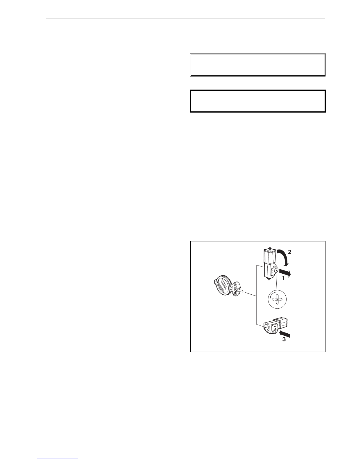
The open or closed positions of the actuator can be
identified either by using compressed air, see Fig. 23,
or by checking the position of the pointer at the end
of the drive shaft. The actuator is closed if the direction of the slot in the coupling plate is transverse to
the direction of the actuator's main line.
Mount the actuator to the valve bracket with four
screws. The tightening screw of the bushing should
be loosened before mounting, to allow the shaft to
fit easily into the actuator.
The actuator construction allows axial movement of
the drive shaft to compensate the valve shaft movement due to e.g. thermal expansion. Check, before
the screw is tightened, that the drive shaft is in the
upper position of its axial movement, which is its
normal position (the mounting position shown in
Fig. 21). Checking is important, as the actuator shaft
drops down slightly when the screw is tightened.
The drive shaft axial movement can be observed and
measured before attachment to a valve. The actuator
drive shaft is in the upper position when its upper
surface conforms to Table 9 (see Fig. 21).
The drive shaft will automatically find its correct posi-
tion if the installation tool H061904 (see Fig. 21) is
used. The installation tool is attached instead of the
coupling plate using M4 screws with the drive shaft in
lower position (before the valve is installed). Tighten
the nut of the tool in such a way that the tool pulls the
drive shaft to the uppermost position. The position
may be checked from the side of the tool.
Install the actuator on the valve and attach the valve
mounting screws loosely by hand. Then tighten the
tightening screw (I) according to Table 9. The
required torque is also marked on a plate close to the
drive shaft on the actuator housing. The installation
tool is removed, and the coupling plate is reattached. Finally, tighten the valve mounting screws.
Check the axial position of the drive shaft. The shaft
position may not be at the upper or lower position X
given in Table 9, or close to those values. Remount
the actuator if the position is not correct.
The valve may malfunction if the tightening of
the connection has been carried out improperly.
Finally, the extreme rotation positions of the valve
are adjusted with the adjustment screws at the ends
of the actuator. The location of the screws for adjusting the close and open positions of the valve are
marked on the actuator housing (see Fig. 22). See
Section 6.5.
Fig. 20. Cone bushing installation
Fig. 21 Tightening of the cone bushing
Fig. 22. Keyway positions on the actuator
Loctite 225 or
similar
Key
X
Installation tool
H061904
DIN keyways at bushing
split
ANSI keyways in the
middle of bushing
ACTUATOR IN CLOSED POSITION
Fig. 23. Actuator connections
Table 9 Mounting faces, tightening screws and drive
shaft clearances
Size Mounting Thread Key Nm~Xupper pos.
(mm)
~X
lower pos.
(mm)
EC/EJ05 F05 M12 6 25 4.0 1
EC/EJ07 F07 M16 8 50 1.5 -2
EC/EJ10 F10 M20 10 100 2.5 -2
EC/EJ12 F12 M24 14 200 3.5 -2
EC/EJ14 F14 M36 19 700 4.5 -2
Closing pressure
Stop screw for
open position
Stop screw for
closed position
Opening
pressure
2 L12 71 en 13
6.3.2 Mounting B series actuators
Turn the valve to the closed position before mount-
ing the actuator.
Clean the shaft and the shaft bore and file off any
burrs which could interfere with mounting. Protect
the joint surfaces from corrosion, e.g. with Cortec VCI
369.
If a bushing is required between the actuator shaft
bore and the valve shaft, mount it first in the actuator shaft bore. Lock the bushing with a retainer
screw.
The valve keyway is on the side opposite the flat side
of the disc. The actuator shaft bore has two keyways
set 90° apart.
For double-acting cylinder actuator, B1C, and spring-
return cylinder actuator, B1J (spring-to-close),
choose the keyway which establishes the piston in
its upper position (at the top end of the cylinder)
when the valve is closed.
In the spring-return cylinder actuator B1JA (spring-
to-open), choose the keyway which establishes the
piston in its lower position when the valve is open.
In valves with manual operation the disc must be
closed by turning the handwheel clockwise.
Check visually that the actuator is correctly posi-
tioned relative to the valve. Tighten all the fastening
screws as tightly as possible.
Adjust the stop screws to the closed position (see
Section 6.5).
The opening angle in a control valve is usually lim-
ited by a bolt to 80°. The opening angle of a shut-off
valve is 90°.
When a shaft extension is required, the sizing of the
shaft extension must be discussed with the valve
manufacturer.
6.4 Detaching and mounting the other
actuator types
See the actuator’s manual for details.
6.5 Stop screw adjustment
6.5.1 General
Close the metal seated triple eccentric disc valve by turning
the disc with a torque wrench against the seat. Choose the
torque from Table 11 for adjusting the stop screw to the
closed position of the actuator. Try not to exceed the given
values since excessive torque would strain the seat and the
joint between the disc and the shaft. Always readjust the
stop screw after changing the seat and after mounting the
actuator.
Before adjusting check that the flange ring screws are tight
and that the ring and body are assembled correctly. Adjust
the stop screw preferably when the valve is fastened in the
pressure test unit.
6.5.2 Actuators other than tabulated
Close the valve as per the tabulated torque Mc and adjust
the stops accordingly. Note the increased torque created by
the actuator while the valve is closed.
6.5.3 Changing the mounting position
Always remove the actuator from the valve shaft before
mounting it into another key groove. Readjust the closed
position limit as instructed.
If manually operated, the valve should close when the
handwheel is turned clockwise. In a double-action cylinder,
the piston must be in the upper position of the cylinder
when the valve is closed. In this position the actuator creates maximum torque. Do not turn the disc more than 90°
as this could damage the seat.
6.5.4 Double-acting cylinder actuator B1C
Apply the tabulated (Table 10) shut-off pressure Pc
to the air connection at the cylinder base.
With the stop screw removed, check through the air
connection hole that the piston does not touch the
cylinder end. If it does, loosen the bracket screws
and turn the actuator clockwise to increase the
adjusting margin.
Turn the closed position stop screw until it touches
the piston, then turn back 1/4 turn and lock up. An
O-ring is used for leakproofing the stop screw.
An extra long screw is needed for opening angles
<80°.
NOTE:
Metso accepts no responsibility for compatibility of actuators not installed by Metso.
CAUTION:
The actuator must not be removed from the valve in a
pipeline under pressure as a result of dynamic torque!
Fig. 24 Changing the mounting position

14 2 L12 71 en
6.5.5 Double-acting diaphragm actuators EC
Follow instructions in Section 6.5.4
6.5.6 Spring-return cylinder actuator B1J
Spring-to-close
Before mounting the cylinder, screw in the closed
position stop screw completely.
The Table 11 indicates *) spring when the spring-cre-
ated torque does not exceed the maximum permitted closing torque Mc. Otherwise, apply the
tabulated pressure Pc into the air connection at the
cylinder end against the spring force. The stop screw
cannot be removed when the cylinder is pressurized!
Open the stop screw until it does not touch the piston.
Turn the closed position stop screw until it touches
the piston, then turn back 1/4 turn and lock up. An
O-ring is used for leakproofing the stop screw.
After adjusting, check the adjusting margin through
the air connection hole. The piston must not touch
the cylinder end. If necessary, increase the margin by
loosening the bracket screws and turning the actuator clockwise.
An extra long screw is needed for opening angles
<80°.
6.5.7 Spring-return cylinder actuator B1JA
Spring-to-open
The actuator being unpressurized the valve is open.
Unscrew the close limit stop screw (actuator housing). Apply tabulated (Table 11) shut-off pressure Pc
to the air connection at the cylinder bottom end
against the spring force to close the valve.
Check through the stop screw hole that the piston rod
does not touch the cylinder top end. If it does, loosen
the bracket screws and turn the actuator clockwise to
increase the adjusting margin.
Turn the closed position stop screw until it touches
the piston, then turn back 1/4 turn and lock up. An
O-ring is used for leakproofing the stop screw.
An extra long screw is needed for opening angles
<80°.
6.5.8 Spring-return diaphragm actuators EJ
Spring-to-close
Follow instructions in Section 6.5.6
Spring-to-open
Follow instructions in Section 6.5.7
6.5.9 Manual operator M
Close the valve as per the tabulated primary torque
M1 (handwheel torque) given in Table 11.
Tighten the closed position stop screw until it
touches the linkage, then turn back 1/4 turn and lock
up with Loctite 225.
Fig. 25 Cylinder actuator, Series B1C
Fig. 26 Cylinder actuator, Series B1J
Stop screw for the
Stop screw
closed position
for the open
position
Stop screw
for the open
position
Stop screw
for the closed
position
Fig. 27 Cylinder actuator, Series B1JA
Fig. 28 Manual operator, series M
Stop screw
for the open
position
Stop screw
for the closed
position
Stop screw
for the closed
position
Stop screw
for the open
position

2 L12 71 en 15
6.5.10 Hand lever RH
Mount the hand lever on the valve, but do not fasten
hex screws (A). Turn the lever using force F in Table
10.
When closing torque is applied, turn the housing (B)
cog of the closing limit to maintain contact with the
lever arm. Fasten hex screws (A).
6.5.11 Electric operator
Instructions for adjustment are given in a separate
leaflet code D304568, which is available from the
manufacturer.
7 TOOLS
No special tools are needed for servicing the valve. However, we recommend an extractor for removing the actuator from the valve. The tool can be ordered from the
manufacturer.
8 ORDERING SPARE PARTS
When ordering spare parts, always include the following
information:
type code, sales order number, serial number
(stamped on a valve body)
number of the parts list, part number, name of the
part and quantity required
This information can be found from the identification plate
or documents.
Fig. 29 Hand lever, Series RH
Table 10 Hand lever RH, adjustment values
Size L L1 Torque F
DN"mm"mm"Nmlbf ftNlbf
80 03 400 16 350 14 40 30 115 26
100 04 400 16 350 14 70 52 200 45
125 05 400 16 350 14 100 74 285 63
150 06 500 20 450 18 135 100 300 67
Fig. 30 Electric operator
Table 11 Extractor tools (Actuator Series B1C/B1J)
Product: ID:
B1C/B1J 6 303821
B1C 8-11 / B1J 8-10 8546-1
B1C 12-17 / B1J 12-16 8546-2
B1C/B1J 20
8546-3

16 2 L12 71 en
Table 12 Series L12, closing torques
DN
SIZE
Mc
BC & BJ
SIZE
BC pc BJ pc BJA
**)
pc BJK pc BJKA
**)
pc BJV pc B JVA
**)
pc EC & EJ EC pc EJ pc E JA
**)
pc
Manual
operator
Input torque M1
80
3
(Nm) (lbf ft) (bar) (psi) (bar) (psi) (bar) (psi) (bar) (psi) (bar) (psi) (bar) (psi) (bar) (psi) SIZE (bar) (psi) (bar) (psi) (bar) (psi) (Nm) (lbf ft)
45 33
62.536 5M0743
8 2.1 30 0.7 10 3.3 48 0 .3 4 2.8 41 1.1 16 4 58 7 3.4 49 0.1 1 4.2 61 AR11 4 3
10 1.6 23 1. 1 16 2.8 41 0.7 10 2.2 32 1.6 23 3.4 49 1 0
100
4"
75 55
64.159 5M0775
8 3.4 49 0.2 3 3.8 55 *)spring 3.3 48 0.6 9 4.6 68 7 AR11 6 4
92.130 10 2.3 33 0.7 10 3.7 54
101.9280.9133.1450.5 7 2.6381.4203.754 12
11 1.1 16 14
125
5"
110 80
6687 5M07107
8 5 72 *)spring 4.5 65 3.8 55 *) spring 5.3 77 7 AR11 9 7
9343 10 3.4 49 0.1 1 4.2 61
10 2.4 35 0.6 9 3. 4 49 0.2 3 2.9 42 1.1 16 4 58 12 1.4 20 1.1 16 3.3 48
11 1.5 22 14
12 1.3 19 1. 1 16 2.9 42 0.7 10 2.2 32 1.6 23 3.7 54
150
6"
150 110
6 8.2 119 5 M07 14 10
94.159 7AR11129
10 3.3 48 0.2 3 3.8 55 *)spring 3.2 46 0.8 12 4.3 62 10 4.6 67 *)spring 4.9 71
11 2.1 30 12 1.9 28 0.8 12 3.6 52
121.6230.9133.1450.5 7 2.6381.5223.957 14
200
8"
300 220
10 6.5 94 *)spring 5 72 4.4 64 *)spring 5.6 81 5 M10 27 20
11 4.2 61 7AR112418
12 3.3 48 0. 2 3 3.8 55 *)spring 3. 2 46 0.8 12 4.6 68 1 0
13 2.1 30 12 3.8 55 *)spring 4.5 65
161.6230.9133.1450.5 7 2.6381.3193.855 14
250
10"
350 260
11 4.9 71 5 M10 32 24
12 3.9 57 0. 1 1 4 58 *)spring 3.4 49 0. 6 9 4 .8 70 7 AR11 28 21
13 2.4 35 10 AR21 20 15
16 1.9 28 0. 7 10 3.2 46 0.4 6 2. 7 39 1.2 17 4 58 12 4.5 65 *)spring 4.8 70
17 1.3 19 14 1.8 26 0.9 13 3.3 48
300
12"
580 430
13 4 58 7 M12 51 38
16 3.2 46 0.3 4 3. 7 54 *) spring 3.2 46 0. 8 12 4.5 65 10 AR21 34 25
17 2.1 30 12
201.7250.8123.1450.5 7 2.6381.4203.652 14 3 440.3 4 4 58
350
14"
800 590
13 5.6 81 7 M12 67 49
16 4.4 64 *)spring 4.2 61 3.6 52 0.4 6 4.9 71 10 M14 49 36
17 2.9 42 12 AR21 46 34
20 2.3 33 0 .6 9 3.3 48 0.3 4 2.8 41 1.2 17 3.8 55 14 4.2 61 *)spring 4.5 65
400
16"
1160 860
16 6.4 93 *)spring 4.9 71 4.3 62 *)spring 5.7 83 M14 72 53
17 4.2 61 AR21 67 50
20 3.3 48 0. 3 4 3.7 54 *)spring 3. 1 45 0.8 12 4.2 61 AR31 50 37
251.7250.8123.1450.5 7 2.6381.4203.652
500
20"
1900 1400
20 5.4 78 *)spring 4.5 65 3.9 57 0 0 5 73 M14 145 107
252.8410.573.5510.112.942 114 4 58 M15 93 69
AR31 80 60
600
24"
3100 2290
25 4.5 65 *)spring 4.1 59 3.5 51 0.4 6 4.7 68 M1 5 163 120
322.2320.7103.3480.3 4 2.8411.2173.957 M16 117 86
AR41 130 95
*) spring = spring torque not adequete to reach tightness according to ISO 5208 Rate D, BS 6755 Part 1 Rate D, ANSI/FCI 70.2 Class V, IEC 534-4 or MSS-SP72/1970
**) Adjust the supply pressure regulator to the pressure below. Do not exceed given value.

2 L12 71 en 17
Table 11 Continued
DN
SIZE
Mc
BC & BJ
SIZE
BC pc BJ pc BJA
**)
pc BJK pc BJK A
**)
pc BJV pc BJVA
**)
pc EC & EJ EC pc EJ pc E JA
**)
pc
Manual
operator
Input torque M1
(Nm) (lbf ft) (bar) (psi) (bar) (psi) (bar) (psi) (bar) (psi) (bar) (psi ) (bar) (psi) (bar) (psi) SIZE (bar) (psi)(bar)(psi)(bar)(psi) (Nm)(lbf ft)
700
28"
3500 2580
25 5.1 74 *)spring 4.3 62 *)spring - 0.1 1 0.5 7 M16 132 97
32 2.6 38 0. 5 7 3.4 49 0.2 3 2.8 41 1.0 15 3.9 57 AR41 147 108
800
32"
5000 3685
32 3.6 52 0. 2 3 3.8 55 *)spring 3.2 46 0.6 9 4.3 62 M25 182 134
40 1.5 22 AR41 147 108
900
36"
6500 4790
32 4.7 68 *)spring 4.2 61 - 3.6 52 0.3 4 4.7 68 M25 236 174
3220.690.693.4490.232.7391.1163.957
40 2.3 33 -
1000
40"
8500 6260
322 0.8 12 0.4 6 3.6 52 *)spring 2.9 4 2 0.8 12 4.1 59
40 3.0 43 -
1200
48"
10500 7740
322 0.1 1 3.9 57 *)spring 3.2 46
40 3.7 54
50 1.9 28
1400
56"
14500 10690
322 *)spring 4.4 64 3.7 54
40 5.1 74
50 2.6 38
*) spring = spring torque not adequete to reach tightness according to ISO 5208 Rate D, BS 6755 Part 1 Rate D, ANSI/FCI 70.2 Class V, IEC 534-4 or MSS-SP72/1970
**) Adjust the supply pressure regulator to the pressure below. Do not exceed given value.

18 2 L12 71 en
9 EXPLODED VIEW AND PARTS LIST
Spare part category 1: Recommended soft parts, always needed for the repair. Delivered as a set.
Spare part category 2: Parts for replacing of the seat
Spare part category 3: Parts for replacing of the closing element
Spares for the full overhaul: All parts from the categories 1, 2 and 3
26
10
18
16
29
30
1
15
20
9
42
24
25
14
13
11
3
4
12
2
27
14
DN 80 - 600
DN 700 - 1400
19
28
44
Charge number
ID number
Mgf number
Item Qty Description Spare part category
11Body
21Clamp ring
3 1 Disc (sizes DN 700–1400) 3
4 1 Seat ring (sizes DN 700–1400) 2
91Gland
10 1 Blind flange
11 1 Drive shaft (sizes DN 700–1400) 3
12 1 Shaft (sizes DN 700–1400) 3
13 1 Key 3
14 3 Pin (sizes DN 700–1400) 3
15 1 Bearing (sizes DN 700–1400) 3
16 1 Bearing (sizes DN 700–1400) 3
18 1 Gasket 1
19 1 Body seal (sizes DN 700–1400) 1
20 5 Gland packing 1
24 2 Stud
25 2 Hexagon nut
26 Hexagon screw
27 6/8 Hexagon socket screw
28 1 Lifting eye bolt (sizes DN 1200, 1400)
29 1 Identification plate
42 2 Retaining plate
44 2 Disc spring set (sizes DN 700–1400)

2 L12 71 en 19
10 DIMENSIONS AND WEIGHTS
ø O
M
SIZE 500 - 1000 / 20" - 40"
R
E
C
N
P
DN
ø B
A1
A
S
V
U
S
V
U
SIZES 80,100,125, / 3", 4", 5"
SIZES 150-800 / 6" - 32"
SIZES 900, 1000 / 36", 40"
T
S
V
U
T
K
Type DN
Dimensions, mm Thread
kg
AA1øBCEKSTORMPNUV
L12A 80 80 47 20 132 80 213 190 70 - 15 105 4.763 17 25 M12 M8 4
L12A 100 100 52 25 160 100 256 220 90 - 20 125 4.763 22.2 35 M12 M8 5
L12A 125 125 56 27 180 115 269 235 90 - 20 125 4.763 22.2 35 M12 M8 7
L12A 150 150 56 28 216 130 305 270 110 32 20 125 4.763 22.2 35 M12 M8 11
L12A 200 200 61 27 272 160 346 300 110 32 25 136 6.35 27.8 46 M12 M10 16
L12A 250 250 68 32 327 200 376 330 130 32 25 156 6.35 27.8 46 M12 M10 27
L12A 300 300 78 34 373 270 409 360 130 32 30 159 6.35 32.9 51 M12 M10 40
L12A 350 350 78 34 416 310 473 415 160 40 35 178 9.525 39.1 58 M16 M10 4 5
L12A 400 400 102 45 480 330 513 445 160 40 40 188 9.525 44.2 68 M16 M10 7 5
L12A 500 500 127 63.5 590 420 610 520 160 55 50 230 12.7 55.5 90 M20 M14 120
L12A 600 600 154 77 690 480 739 620 230 90 70 299 19.05 78.2 119 M24 M16 220
L12B 700 700 165 65 800 536 829 710 230 90 70 299 19.05 78.2 119 M24 M16 331
L12B 800 800 190 80 900 622 937 791 230 90 85 326 22.225 94.7 146 M24 M16 489
L12B 900 900 203 91.4 1000 678 1058 902 330 120 95 376 22.225 104.8 156 M30 M20 651
L12B 1000 1000 2 16 95 1110 728 1108 952 330 120 95 376 22.225 104.8 156 M30 M20 805
L12B 1200 1200 2 54 108 1330 855 1250 1080 330 120 105 400 25.4 116. 2 170 M30 M20 1200
L12B 1400 1400 2 79 118 1540 950 1395 1200 360 135 120 455 31.75 133.8 195 M30 M20 1900
Type Size
Dimensions, in Thread
lb
AA1øBCEKSTORMPNUV
L12A 80 3 1.85 0.79 5.20 3. 15 8.39 7.48 2.76 - 0 .59 4.13 0.19 0.67 0.98 M1 2 M8 8.8
L12A 100 4 2.05 0.9 8 6.30 3.94 10.08 8.66 3.54 - 0.79 4.92 0.19 0.87 1.38 M12 M8 11
L12A 125 5 2.20 1.0 6 7.48 4.53 10.59 9.25 3.54 - 0.79 4.92 0.19 0.87 1.38 M12 M8 15.4
L12A 150 6 2.20 1.10 8.50 5.12 12.01 10.63 4.33 1.26 0.79 4.92 0.19 0.87 1.38 M12 M8 24.2
L12A 200 8 2.40 1.06 10.71 6.30 13.62 11.81 4.33 1.26 0.98 5.35 0.25 1.09 1.81 M12 M10 35.2
L12A 250 10 2.68 1.26 12.87 7.87 14.80 12.9 9 5.1 2 1.26 0.98 6.14 0.25 1.09 1.81 M12 M10 59.4
L12A 300 12 3.07 1.34 14.69 10.6 3 16.10 14 .17 5.12 1.26 1.18 6.26 0.25 1.30 2.01 M12 M10 8 8
L12A 350 14 3.07 1.34 16.38 12.2 0 18.62 16 .34 6.30 1.57 1.38 7.01 0.38 1.54 2.28 M16 M10 9 9
L12A 400 16 4.02 1.77 18.90 12.9 9 20.20 17 .52 6 .30 1.57 1.57 7.40 0.38 1.74 2.68 M16 M10 165
L12A 500 20 5.00 2.50 23.23 16.5 4 24.02 20 .47 6 .30 2.17 1.97 9.06 0.50 2.19 3.54 M20 M14 264
L12A 600 24 6.06 3.03 27.17 18.9 0 29.09 24.4 1 9 .06 3.54 2.76 11.77 0.75 3.08 4.69 M2 4 M16 484
L12B 700 28 6.5 2.5 5 31.5 21.1 32.64 27.95 9.05 3.54 2.7 6 11.77 0.75 3.08 4.68 M24 M16 730
L12B 800 32 7.48 3.15 35.4 24.5 36.89 31.14 9.05 3.54 3.35 12.83 0.875 3.72 5.75 M24 M16 1078
L12B 900 36 8 3.6 39 .4 26.7 41.65 35.51 13 4.72 3.74 14.80 0.875 4.13 6.14 M30 M20 14 35
L12B 1000 40 8.5 3.74 43.7 28.7 43.62 37.48 13 4.72 3.74 14.80 0.875 4.13 6.14 M30 M20 1774
L12B 1200 48 10.00 4.25 52.36 33.66 49.21 42.52 12.99 4.72 4.13 15.75 1.00 4.57 6.69 M30 M20 2640
L12B 1400 56 10.98 4.65 60.63 37.40 54.92 47.24 14.17 5.31 4.72 17.91 1.25 5.27 7.68 M30 M20 4180
C
DN
H
J
¯B
A
A1
L
K
L12 - RH
Dimensions, mm
kg
DNAA1øBCHJKL
L12A 80-RH415 80 47 20 132 80 293 213 100 400 5
L12A 100-RH420 100 52 25 160 100 356 256 100 400 6
L12A 125-RH420 125 56 27 190 115 384 269 100 400 8
L12A 150-RH520 150 56 28 216 130 435 305 130 520 12
Dimensions, in
lb
SizeAA1øBCHJKL
L12A 80-RH415 3 1.85 0.79 5.20 3.15 13.39 8.39 3.94 15.75 11
L12A 100-RH420 4 2.05 0.98 6.30 3.94 14.02 10.08 3.94 15.75 13
L12A 125-RH420 5 2.20 1.06 7.48 4.53 15.12 10.59 3.94 15.75 18
L12A 150-RH520 6 2.20 1.10 8.50 5.12 17.13 12.01 5.12 20.47 26

20 2 L12 71 en
Type D N
Dimensions, mm
NPT kg
øB F G J K V X
EC07 80 132 300 150 214 190 24 117 1/4 14
EC10
100 160 405 203 253 220 32 155 1/4 23
125 190 405 203 268 235 32 155 1/4 25
150 216 405 203 328 270 32 155 1/4 30
EC12
125 190 495 248 290 235 42 200 1/4 42
150 216 495 248 350 270 42 200 1/4 47
200 272 495 248 380 300 42 200 1/4 52
250 327 495 248 400 330 42 200 1/4 64
EC14
250 327 675 338 460 330 56 259 1/4 105
300 372 675 338 460 360 56 259 1/4 118
350 416 675 338 525 415 56 259 1/4 122
Type S ize
Dimensions, in
NPT lb
øB F G J K V X
EC07 3 5.2 11.81 5.91 8.43 7.48 0.94 4.61 1/4 31
EC10
4 6.3 15.94 7.99 9.96 8.66 1.26 6.1 1/4 51
5 7.48 15.94 7.99 10.55 9.25 1.26 6.1 1/4 55
6 8.5 15.94 7.99 12.91 10 .63 1.26 6.1 1/4 66
EC12
5 7.48 19.49 9.76 11.42 9.25 1.65 7.84 1/4 93
6 8.5 19.49 9.76 13.78 10 .63 1.65 7.84 1/4 104
8 1 0.71 19.49 9.76 14.96 11.81 1.65 7.84 1/4 115
10 12.87 19.49 9.76 15.75 12.99 1.65 7.84 1/4 141
EC14
10 12.87 26.57 13.31 18.11 12.99 2.2 10.2 1/4 232
12 14.69 26.57 13.31 18.11 14.17 2.2 10.2 1/4 260
14 16.38 26.57 13.31 20.67 16.34 2.2 10.2 1/4 269
V
F
G
øB
K
J
øZ
L12 - M
X
G
F
J
V
K
øB
VDI/VDE 3845
G1/4"
Supply
G1/4"
L12 - EC
Type
Dimensions, mm
kg
FGJ VZ
M07 241 185 65 52 160 4
M10 241 185 65 52 200 4
M12 304 235 88 71 315 10
M14 405 305 93 86 400 18
M15 456 346 102 105 500 26
M16 530 387 124 130 500 37
M25 597 412 160 182 600 61
Type
Dimensions, in
lb
FGJ VZ
M07 9.49 7.28 2.56 2.05 6.30 9
M10 9.49 7.28 2.56 2.05 7.87 9
M12 11.97 9. 25 3.46 2.80 12.40 22
M14 15.94 12.01 3.66 3.39 15.75 40
M15 17.95 13.62 4.02 4.13 19.69 57
M16 20.87 15.24 4.88 5.12 19.69 81
M25 23.50 16.22 6.30 7.17 23.62 134
Type D N
Dimensions, mm
NPT kg
øB F G J K V X
EJ07 80 132 443 293 172 190 24 117 1/4 17
EJ10
100 160 606 403 191 220 32 155 1/4 30
125 190 606 403 191 235 32 155 1/4 32
EJ12
125 190 770 522 214 235 42 200 1/4 61
150 216 770 522 214 270 42 200 1/4 62
200 272 770 522 214 300 42 200 1/4 71
EJ14
250 327 1030 692 243 330 56 259 1/4 142
300 373 1030 692 243 360 56 259 1/4 155
Type Size
Dimensions, in
NPT lb
øB F G J K V X
EJ07 3 5.2 17.44 11.54 6.77 7.48 0.94 4.61 1/4 37
EJ10
4 6.3 23.86 15. 87 7.52 8.66 1.26 6.1 1/4 66
5 7.48 23.86 15. 87 7.52 9.25 1.26 6.1 1/4 71
EJ12
5 7.48 30.31 20. 55 8.43 9.25 1.65 7.84 1/4 134
6 8.5 30.31 20. 55 8.43 10.63 1.65 7. 84 1/4 137
8 10.71 30 .31 20.55 8.43 11.81 1.65 7.84 1/4 157
EJ14
10 12.87 40.55 27.24 9.57 12.99 2.2 10.2 1/4 313
12 14.69 40.55 27.24 9.57 14.17 2.2 10.2 1/4 342
K
øB
F
Supply
G1/4"
J
G
V
X
VDI/VDE 3845
G1/4"
L12 - EJ

2 L12 71 en 21
See K and øB dimensions on page 18.
Type
Dimensions, mm
NPT kg
XGFV J
B1C6 90 260 400 36 283 1/4 4.2
B1C9 110 315 455 43 279 1/4 9.6
B1C11 135 375 540 51 290 3/8 16
B1C13 175 445 635 65 316 3/8 31
B1C17 215 545 770 78 351 1/2 54
B1C20 215 575 840 97 385 1/2 73
B1C25 265 710 1040 121 448 1/2 131
B1C32 395 910 1330 153 525 3/4 256
B1C40 505 1150 1660 194 595 3/4 446
B1C50 610 1350 1970 242 690 1 830
Type
Dimensions, in
NPT lb
XGFV J
B1C6 3.54 10.24 15.75 1.42 11.14 1/4 9
B1C9 4.33 12.40 17.91 1.69 10.98 1/4 21
B1C11 5.31 14.76 21.26 2.01 11.42 3/8 35
B1C13 6.89 17.52 25.00 2.56 12.44 3/8 68
B1C17 8.46 21.46 30.31 3.07 13.82 1/2 119
B1C20 8.46 22.64 33.07 3.82 15.16 1/2 161
B1C25 10.43 27.95 40.94 4.76 17.64 1/2 289
B1C32 15.55 35.83 52.36 6.02 20.67 3/4 564
B1C40 19.88 45.28 65.35 7.64 23.43 3/4 983
B1C50 24.02 53.15 77.56 9.53 27.17 1 1829
1/4 NPT
1/4 NPT
NPT
NPT
V
øB
K
J
X
G
F
STANDARD MOUNTING POSITION
L12 - B1C/B1J
Type
Dimensions, mm
NPT kg
XGFV J
B1J, B1JA8 135 420 560 43 279 3/8 17
B1J, B1JA10 175 490 650 51 290 3/8 30
B1J, B1JA12 215 620 800 65 316 1/2 57
B1J, B1JA16 265 760 990 78 351 1/2 100
B1J, B1JA20 395 935 1200 97 358 3/4 175
B1J, B1JA25 505 1200 1530 121 448 3/4 350
B1J, B1JA32 540 1410 1830 153 525 1 671
Type
Dimensions, in
NPT lb
XGFV J
B1J, B1JA8 5.31 16.54 22.05 1.69 10.98 3/8 37
B1J, B1JA10 6.89 19.29 25.59 2.01 11.42 3/8 66
B1J, B1JA12 8.46 24.41 31.50 2.56 12.44 1/2 126
B1J, B1JA16 10.43 29.92 38.98 3.07 13.82 1/2 220
B1J, B1JA20 15.55 36.81 47.24 3.82 14.09 3/4 386
B1J, B1JA25 19.88 47.24 60.24 4.76 17.64 3/4 771
B1J, B1JA32 21.26 55.51 72.05 6.02 20.67 1 1479

22 2 L12 71 en
11 TYPE CODE
NELDISC® HIGH PERFORMANCE TRIPLE ECCENTRIC DISC VALVE,
series L12
1. 2. 3. 4. 5. 6. 7. 8.
L12 A 150 A A - / K
1. PRODUCT SERIES
L12
Wafer type, full bore, metal-seated
Face-to-face lenght acc. to API 609
2. PRESSURE RATINGS
A
Body rating
DN 80–125: PN 50 / ASME 300
DN 150–600: PN 25 / ASME 150
Maximum shut-off pressure
DN 80–125 Ps = 25 bar (ASME 150), welded clamp ring
DN 150 Ps = 25 bar, welded clamp ring
DN 200 Ps = 20 bar, welded clamp ring
DN 250–600 Ps = 10 bar, welded clamp ring
B
Body rating
PN 25 / ASME 150
Maximum shut-off pressure
DN 700–1000 Ps = 10 bar, bolted clamp ring
DN 1200,1400 Ps = 6 bar, bolted clamp ring
3. DIAMETER NOMINAL
080, 100, 125, 150, 200, 250, 300, 350, 400, 500, 600, 700, 800, 900, 1000, 1200, 1400
4. BODY, DISC AND SHAFT MATERIAL
A
Body and disc: stainless steel ASTM A351 gr. CF8M
shaft: SIS 2324, DN 80–1400
H
Body and disc: stainless steel ASTM A351 gr. CF8M
shaft: 17-4PH + hard facing, only DN 700–1400
5. SEAT MATERIAL
A Stainless steel ASTM B 424 (Incoloy 825) hard chrome plated only for DN 80–600
B W.No 1.4418 + hard chrome plated available only for DN 700–1400
6. GLAND PACKING
-
PTFE, standard, without sign (Available only for sizes DN 80–600)
(for sizes DN 700–1400 the sign is always "T")
T
Live loaded PTFE packing with disc springs sets, TA-Luft tested and certified by TÜV.
Sizes DN 80–1400
G
Live loaded graphite packing with disc springs sets, TA-Luft tested and certified by TÜV.
Sizes DN 80–1400
7. FLANGE FACING
-
EN1092-1Type B1, (Ra 3,2–12.5)
Covering:
ASME B16.5, (Ra 3.2–6.3)
old DIN 2526 Form E (Ra 4)
8. FLANGE DRILLING (DN 500 - 1400)
C
ASME B 16.5 Class 150 sizes DN 500–600
ASME B 16.47 Series A Class 150 size 26" and bigger.
J PN 10
K PN 16
L PN 25
R JIS 10K
S JIS 16K

2 L12 71 en 23

Metso Flow Control Inc.
Europe, Vanha Porvoontie 229, P.O. Box 304, FI-01301 Vantaa, Finland. Tel. +358 20 483 150. Fax +358 20 483 151
North America, 44 Bowditch Drive, P.O. Box 8044, Shrewsbury, M A 01545, USA. Tel. +1 508 852 0200. Fax +1 508 852 8172
South America, Av. Independéncia, 2500-Iporanga, 18087-101, Sorocaba-São Paulo, Brazil. Tel. +55 15 2102 9700. Fax +55 15 2102 9748
Asia Pacic, 238B Thomson Road, #17-01 Novena Square Tower B, Singapore 307685. Tel. +65 6511 1011. Fax +65 6250 0830
China, 11/F, China Youth Plaza, No.19 North Rd of East 3rd Ring Rd, Chaoyang District, Beijing 100020, China. Tel. +86 10 6566 6600. Fax +86 10 6566 2583
Middle East, Roundabout 8, Unit AB-07, P.O. Box 17175, Jebel Ali Freezone, Dubai, United Arab Emirates. Tel. +971 4 883 6974. Fax +971 4 883 6836
www.metso.com/valves
24 2 L12 71 en
 Loading...