

Metso neles ND7000H, neles ND9000F, neles ND9000H, neles ND9000P, ND7000H Operating Instructions Manual
...
INTELLIGENT
VALVE CONTROLLER
ND7000H
ND9000H, ND9000F, ND9000P
Rev. 4.0
Installation, Maintenance and
Operating Instructions
7 ND90 71 en • 5/2019

2 7 ND90 71 en
Table of Contents
1 PRODUCT FAMILY SUMMARY.............................. 3
1.1 ND9000 .......................................................................3
1.2 ND7000 .......................................................................4
2 ND9000 AND ND7000 INTELLIGENT VALVE
CONTROLLER WITH DIFFERENT
COMMUNICATION PROTOCOLS .......................... 4
2.1 General........................................................................4
2.2 Technical description.............................................4
2.3 Markings.....................................................................5
2.4 Technical specifications ........................................5
2.5 Recycling and disposal..........................................9
2.6 Safety precautions ..................................................9
3 TRANSPORTATION, RECEPTION AND
STORAGE ............................................................. 10
4 MOUNTING .......................................................... 10
4.1 General ................................................................... 10
4.2 For mounting parts for Metso actuators, see
12.5–12.10.Mounting on Metso actuators
with VDI/VDE mounting face........................... 10
4.3 Mounting on Neles VC and VD actuators or
linear actuators with IEC 60534 mounting
face ............................................................................ 11
4.4 Piping ....................................................................... 12
4.5 Electrical connections......................................... 16
5 LOCAL USER INTERFACE (LUI)............................ 23
5.1 Measurement monitoring................................. 23
5.2 Guided start-up..................................................... 24
5.3 Configuration menu............................................ 24
5.4 Mode menu............................................................ 24
5.5 Configuration parameters ................................ 26
5.6 Valve travel calibration....................................... 28
5.7 Special displays..................................................... 30
5.8 Write protection ................................................... 31
6 MAINTENANCE.................................................... 32
6.1 Prestage................................................................... 32
6.2 Spool valve ............................................................. 32
6.3 Flame arrestor assembly.................................... 33
6.4 Diaphragms............................................................ 33
6.5 Communication board....................................... 33
7 ERROR MESSAGES............................................... 34
7.1 Failsafe errors......................................................... 34
7.2 Alarms ...................................................................... 34
7.3 Errors......................................................................... 34
7.4 Warnings ................................................................. 35
7.5 Notifications........................................................... 36
8 TROUBLE SHOOTING.......................................... 36
9 ND9000 WITH LIMIT SWITCHES ........................ 37
9.1 Introduction............................................................37
9.2 Installation on a valve controller.....................40
9.3 Electrical connections .........................................41
9.4 Adjustment .............................................................41
9.5 Removal of the limit switches for accessing
the valve controller ..............................................41
9.6 Circuit diagrams ....................................................41
9.7 Maintenance...........................................................41
10 TOOLS.................................................................. 41
11 ORDERING SPARE PARTS................................... 41
12 DRAWINGS AND PARTS LISTS ........................... 42
12.1 Exploded view ND9100, ND9400,
ND7100.....................................................................42
12.2 Exploded view ND9100_/D__, ND9100_/I__,
ND9100_/K0_ and ND9100_/B06 ...................43
12.3 Exploded view ND9200, ND9300,
ND7200 ...................................................................44
12.4 Exploded view ND9200_/D__, ND9200_/I__,
ND9200_/K0_, ND9200_/B06,
ND9300_/D__, ND9300_/I__, ND9300_/K0_,
ND9300_/B06_.......................................................46
12.5 Mounting parts for B1C/B1J 6-20
actuators ..................................................................48
12.6 Mounting parts for B1C/B1J 25-50, B1C 502
and B1J322 actuators ..........................................49
12.7 Mounting parts for Quadra-Powr®
actuators ..................................................................50
12.8 Mounting on Neles VC and VD actuators or
linear actuators with IEC 60534 mounting
face.............................................................................51
12.9 Connection diagrams..........................................53
13 DIMENSIONS ................................................... 58
14 EC DECLARATION OF CONFORMITY ................. 60
15 ID PLATES............................................................ 61
16 TYPE CODING...................................................... 62
READ THESE INSTRUCTIONS FIRST!
These instructions provide information about the safe handling and operation of the intelligent valve controller.
If you require additional assistance, please contact the manufacturer or manufacturer's representative.
Addresses and phone numbers are printed on the back cover.
See also www.metso.com/valves for the latest documentation.
SAVE THESE INSTRUCTIONS!
Subject to change without notice.
All trademarks are property of their respective owners.

7 ND90 71 en 3
1 PRODUCT FAMILY SUMMARY
1.1 ND9000
1.1.1 Key features
Benchmark control performance on rotary and linear
valves
Reliable and robust design
Ease of use
Language selection: English, German and French
Local / remote operation
Expandable architecture
Advanced device diagnostics including
Self-diagnostics
- Online diagnostics
- Performance diagnostics
- Communication diagnostics
- Extended off-line tests
- Performance view
- Online Valve Signature
1.1.2 Options
Interchangeable communication options:
HART 6 or 7 (H)
F
OUNDATION fieldbus (F)
Profibus PA (P)
Limit switches
Position transmitter (in HART only)
Stainless steel housing
Exhaust adapter
Remote mounting
Cold version (up to -53 °C)
1.1.3 Total cost of ownership
Low energy and air consumption
Future proof design allows further options at a
reduced cost
Optimised spares program. Reduced number of
spares
Retro-fit to existing installations (Neles or 3rd party)
1.1.4 Minimised process variability
Linearisation of the valve flow characteristics
Excellent dynamic and static control performance
High-speed of response
Accurate internal measurements
1.1.5 Easy installation and configuration
Same unit for linear and rotary valves, double and
single-acting actuators
Simple calibration and configuration
using Local User Interface (H, F, P)
using DTM or EDD in a remote location (H, F)
see 375/475 menu structure from annex 1
using Profibus configurator like Simatic PDM (P)
or DTM
Low power design enables installation to all com-
mon control systems
Ability to attach options to electronics and mechan-
ics later
Possibility to mount also on valves that are in pro-
cess with 1-point calibration feature
1.1.6 Open solution
Metso is committed to delivering products that freely interface with software and hardware from a variety of manufacturers; and the ND9000 is no exception. This open
architecture allows the ND9000 to be integrated with other
field devices to give an unprecedented level of controllability.
FDT based and DD/eEDD multi-vendor support con-
figuration files from download page:
www.metso.com/ND9000
1.1.7 ND9000 in fieldbus networks
Approved interoperability
Host interoperability ensured
F
OUNDATION fieldbus ITK version 6.1.2 certified
Profibus PA profile version 3.0 PNO certified
Easy to upgrade; can be done by replacing the HART
communication board to fieldbus communication
board
Excellent maintainability with firmware download
feature
Advanced communication diagnostics
Digital communication via the fieldbus includes not
only the set point, but also the position feedback signal from the position sensor. No special supplementary modules for analog or digital position feedback
are needed when using the fieldbus valve controller.
Back up LAS functionality available in F
fieldbus enviroment
Input selector and output splitter blocks available in
F
OUNDATION fieldbus devices allowing advanced dis-
tributed control
Multipurpose functionality
Standard function blocks enables the freedom to
use ND9000 intelligent valve controller either in
continuous or on-off control applications
Open and close information directly available via
the fieldbus
Open and close detection is based on either posi-
tion measurement (soft limit switch) or mechanical limit switch information
OUNDATION
1.1.8 Product reliability
Designed to operate in harsh environmental condi-
tions
Rugged modular design
Excellent temperature characteristics
Vibration and impact tolerant
IP66 enclosure
Protected against humidity
Maintenance free operation
Resistant to dirty air
Wear resistant and sealed components
Contactless position measurement
1.1.9 Predictive maintenance
Easy access to collected data with FDT based DTM
Unique Online Valve Signature to detect valve
friction even more accurately.
Performance view with report, which gives
guidelines for recommended actions.
Logical trend and histogram collection
Information collected on service conditions

4 7 ND90 71 en
Extensive set of off-line tests with accurate key
figure calculations
Fast notifications using on-line alarms
Condition monitoring tool available
Real time monitoring of valve control parameters
1.2 ND7000
1.2.1 Key features
Benchmark control performance on rotary and linear
valves
Reliable and robust design
Ease of use
Language selection: English, German and French
Local / remote operation
Expandable architecture
Basic diagnostics including
Self-diagnostics
Online diagnostics
Extended off-line tests
1.2.2 Total cost of ownership
Low energy and air consumption
Retro-fit to existing installations (Neles or 3rd party)
1.2.3 Minimised process variability
Linearisation of the valve flow characteristics
Excellent dynamic and static control performance
High-speed of response
Accurate internal measurements
1.2.4 Easy installation and configuration
Same unit for linear and rotary valves, double and
single-acting actuators
Simple calibration and configuration
using Local User Interface (H)
using DTM or EDD in a remote location (H, F)
see 375/475 menu structure from annex 1
Low power design enables installation to all com-
mon control systems
Possibility to mount also on valves that are in pro-
cess with 1-point calibration feature
1.2.5 Open solution
Metso is committed to delivering products that freely interface
with software and hardware from a variety of manufacturers;
and the ND7000 is no exception. This open architecture allows
the ND7000 to be integrated with other field devices to give an
unprecedented level of controllability.
FDT based multi-vendor support configuration
ND9000 DTM download page:
www.metso.com/ND9000
1.2.6 Product reliability
Designed to operate in harsh environmental condi-
tions
Rugged modular design
Excellent temperature characteristics
Vibration and impact tolerant
IP66 enclosure
Protected against humidity
Maintenance free operation
Resistant to dirty air
Wear resistant and sealed components
Contactless position measurement
2 ND9000 AND ND7000 INTELLIGENT
VALVE CONTROLLER WITH DIFFERENT
COMMUNICATION PROTOCOLS
2.1 General
This manual incorporates Installation, Maintenance and
Operation Instructions for the Metso ND9000 and ND7000
intelligent valve controller. The ND9000 and ND7000 may
be used with either cylinder or diaphragm type pneumatic
actuators for rotary or linear valves.
NOTE:
The selection and use of the valve controller in a specific
application requires close consideration of detailed
aspects. Due to the nature of the product, this manual
cannot cover all the likely situations that may occur when
installing, using or servicing the valve controller.
If you are uncertain about the use of the controller or its
suitability for your intended use, please contact Metso’s
Automation business for more information.
2.2 Technical description
ND9000H and ND7000H
The ND9000H and ND7000H are a 4–20 mA loop-powered
microcontroller-based intelligent valve controllers. The
devices operate even at 3.6 mA input signal and communicates via HART.
ND9000F
The ND9000F is a fieldbus powered microcontroller-based
intelligent valve controller.
ND9000P
The ND9000P is a fieldbus powered microcontroller-based
intelligent valve controller.
All versions
All devices contain a Local User Interface enabling local
configuration.
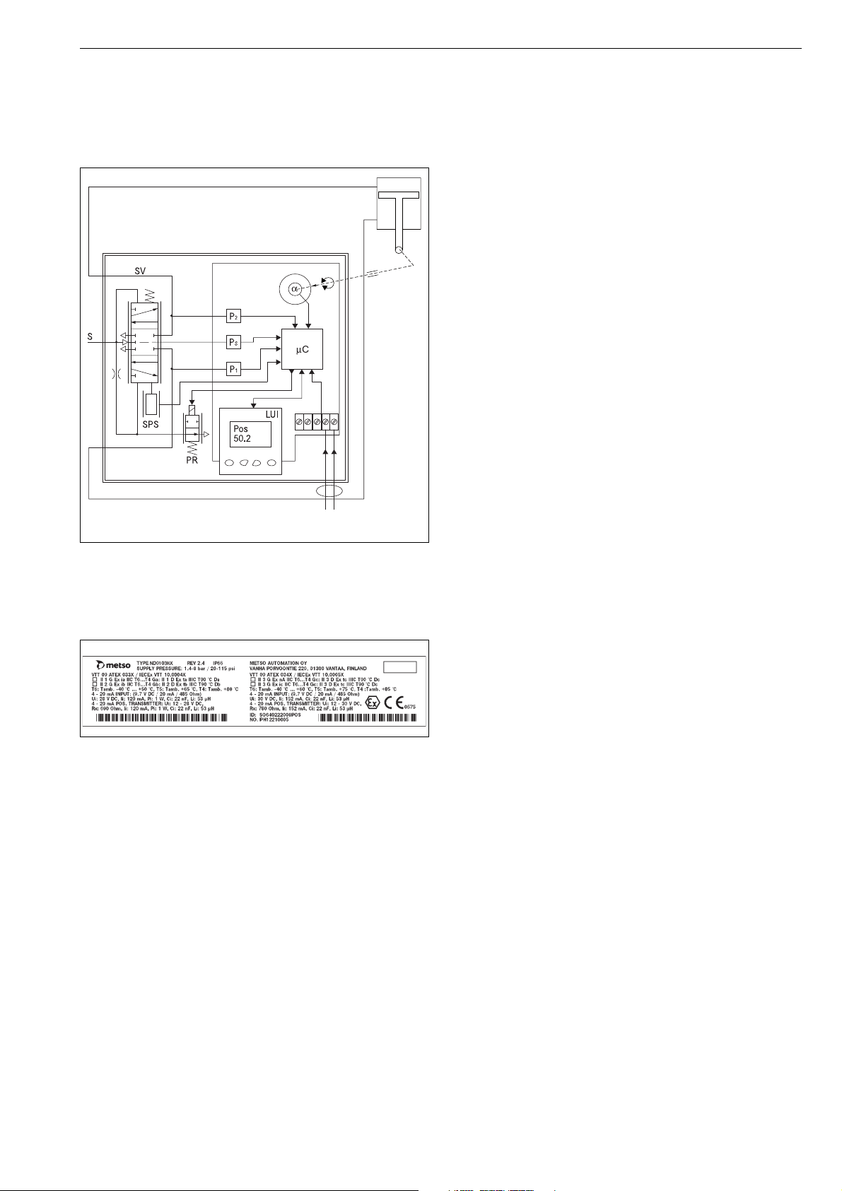
Independently from the communication protocol, the valve
position is controlled by the powerful 32-bit microcontroller. The measurements include:
Input signal
Valve position with contactless sensor
Actuator pressures, 2 independent measurements
Supply pressure
Spool valve position
Device temperature
Advanced self-diagnostics guarantees that all measurements operate correctly. Failure of one measurement does
not cause the valve to fail if the input signal and position
measurements are operating correctly. After connections of
electric signal and pneumatic supply the micro controller
(µC) reads the input signal, position sensor (α), pressure
sensors (Ps, P1, P2) and spool position sensor (SPS). A difference between input signal and position sensor (α) measurement is detected by the control algorithm inside the µC.
The µC calculates a new value for prestage (PR) coil current
based on the information from the input signal and from
the sensors. Changed current to the PR changes the pilot
pressure to the spool valve. Reduced pilot pressure moves
the spool and the actuator pressures change accordingly.
The spool opens the flow to the driving side of the double
diaphragm actuator and opens the flow out from the other
7 ND90 71 en 5
side of the actuator. The increasing pressure will move the
diaphragm piston. The actuator and feedback shaft rotate
clockwise. The position sensor (α) measures the rotation for
the µC. The µC using control algorithm modulates the PRcurrent from the steady state value until a new position of
the actuator according to the input signal is reached.
Fig. 1 The principle of operation
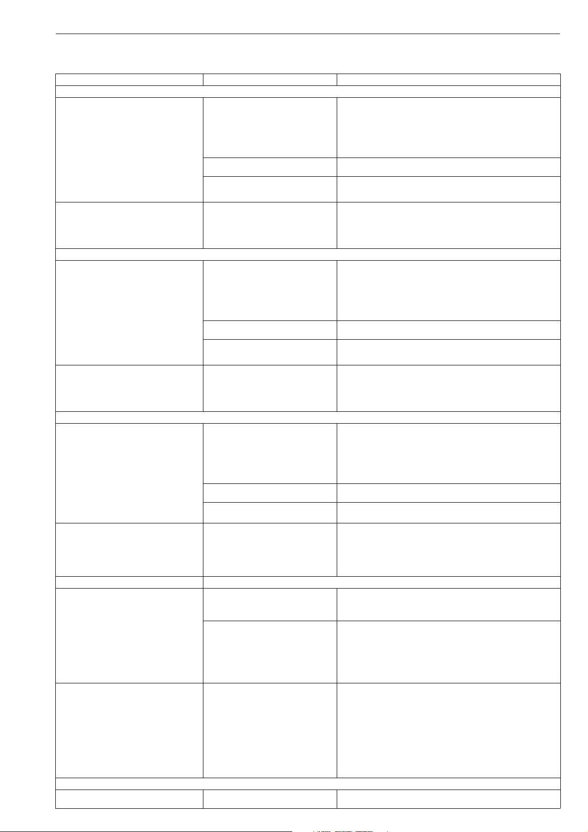
2.3 Markings
The valve controller is equipped with an identification plate
(Fig. 2).
Fig. 2 Example of the identification plate
Identification plate markings include:
Type designation of the valve controller
Revision number
Enclosure class
Input signal (voltage range)
Input resistance
Maximum supply voltage
Operational temperature
Supply pressure range
Contact details of the manufacturer
CE mark
Manufacturing serial number TTYYWWNNNN*)
*) Manufacturing serial number explained:
TT= device and factory sign
YY= year of manufacturing
WW = week of manufacturing
NNNN = consecutive number
Example: PH13011234 = controller, year 2013, week 1, consecutive number 1234.
Note, that in ND9200 and ND9300 models there may have
two identification plates if there is double approval (type
ND92_XE1 or ND93_XE1).
When device is installed to Ed i or Ex d area, remove identification plate which is not valid.
If device is installed to Ex d area, it can't be installed to Ex i
area even that identification plate would be changed.
See Chapter 15 for all ID plates.
2.4 Technical specifications
ND9000 AND ND7000 INTELLIGENT VALVE
CONTROLLER
General
Either loop powered (ND9000H and ND7000H) or
bus powered (ND9000F and ND9000P),
no external power supply required.
Suitable for rotary and sliding-stem valves.
Actuator connections in accordance with VDI/VDE 3845
and IEC 60534-6 standards.
Action: Double or single acting
Trave l ran ge: Linear; 10–120 mm with standard IEC parts.
Larger strokes possible with suitable kits
Rotary; 45–95°.
Measurement range 110° with freely
rotating feedback shaft.
Environmental Influence
Standard temperature range:
-40° to +85 °C / -40° to +185 °F
Low temperature option:
-53° to +85 °C / -64° to +185 °F
Influence of temperature on valve position:
< 0.5 % / 10 °C
Influence of vibration on valve position:
< 1 % under 2g 5–150 Hz,
1g 150–300 Hz, 0.5g 300–2000 Hz
Enclosure
ND9100 and ND7100
Material: Anodised aluminium alloy and
polymer composite
Protection class: IP66, NEMA 4X
Pneumatic ports: G 1/4
Electrical connection: max 2.5 mm
Cable gland thread: M20 x 1.5 / 1/2 NPT (U)
Weight: 1.8 kg / 4.0 lb
with extension housing (limit switches) plus 0.8 kg / 1.8 lb
Mechanical and digital position indicator visible through
the main cover
ND9200 and ND7200
Material: Anodised aluminium alloy and
tempered glass
Protection class: IP66, NEMA 4X
Pneumatic ports: 1/4 NPT
Electrical connection: max. 2.5 mm
Cable gland thread: M20 x 1.5, except 1/2 NPT (E2)
Weight: 3.4 kg / 7.5 lb
with extension housing (limit switches) plus 1.0 kg / 2.2 lb
Mechanical and digital position indicator visible through
the main cover (not applicable to ND9200_E2)
2
2

6 7 ND90 71 en
ND9300 and ND9400
Material: Full stainless steel enclosure (ND9300)
Stainless steel housing and polymer
composite cover (ND9400)
Protection class: IP66, NEMA 4X
Pneumatic ports: 1/4 NPT
Electrical connection: max. 2.5 mm
2
Cable gland thread: M20 x 1.5 / 1/2 NPT (U and E2)
Weight: 5.6 kg / 12.4 lbs (ND9400)
8.6 kg / 19.0 lbs (ND9300)
with extension housing (limit switches) plus 3.0 kg / 6.6 lb
Pneumatics
Supply pressure: 1.4–8 bar / 20–115 psi
Effect of supply pressure on valve position:
< 0.1 % at 10 % difference in inlet pressure
Air quality: According to ISO 8573-1:2001
Solid particles: Class 5
(3–5 µm filtration is recommended)
Humidity: Class 1
(dew point 10 °C / 18 °F below minimum
temperature is recommended)
Oil class: 3 (or <1 ppm)
Capacity with 4 bar / 60 psi supply:
5.5 Nm
12 Nm
38 Nm
3
/h / 3.3 scfm (spool valve 2)
3
/h / 7.1 scfm (spool valve 3)
3
/h / 22.4 scfm (spool valve 6)
Consumption with 4 bar / 60 psi supply
in steady state position:
< 0.6 Nm
< 1.0 Nm
3
/h / 0.35 scfm (spool valves 2 & 3)
3
/h / 0.6 scfm (spool valve 6)
Electronics
ND9000H and ND7000H
Supply power: Loop powered, 4–20 mA
Minimum signal: 3.6 mA
Current max : 120 mA
Load voltage: up to 9.7 V DC / 20 mA
(corresponding 485 Ω)
Voltage: max 30 V DC
Polarity protection: -30 V DC
Over current protection:
active over 35 mA
ND9000F and ND9000P
Power supply: Taken from bus
Bus voltage: 9–32 V DC, reverse polarity protection
Quiescent Current
Draw: 16 mA
Max basic current: 17.2 mA
Fault current (FDE): 3.9 mA
F
OUNDATION fieldbus function block execution times
ND9000F
AO 20 ms
AI 20 ms
PID 20 ms
DO 20 ms
DI 15 ms
IS 15 ms
OS 15ms
Performance with moderate constant-load actuators
Values at 20 °C / 68 °F and without any additional instruments, such as boosters or quick exhaust valves etc.
Dead band: ≤ 0.1 %
Hysteresis: < 0.5 %
Local user interface functions
Local control of the valve
Monitoring of valve position, input signal, tempera-
ture, supply and actuator pressure difference
Guided start-up function
LUI may be locked remotely to prevent unauthorised
access
Calibration: Automatic/Manual/Linearization
1-point calibration
Control configuration: aggressive, fast, optimum,
stable, maximum stability
Mode selection: Automatic/Manual
Rotation: valve rotation clockwise or counterclock-
wise to close
Dead angle
Low cut-off, cut-off safety range (default 2 %)
Positioner fail action, open/close
Signal direction: Direct/reverse acting
Actuator type, double/single acting
HART version: HART 6 or HART 7
Valve type, rotary/linear IEC/nelesCV Globe/FLI
Language selection: English, German and French
Electromagnetic protection
Electromagnetic compability acc. to
Emission: EN 61000-6-4 (2007) + A1(2011)
Immunity: EN 61000-6-2 (2005)
Safety
IEC 61508 compliant up to and
including SIL 2 by TUV
CE marking
EMC 2014/30/EU
ATEX 94/9/EC (until 19 April 2016)
ATEX 2014/34/EU (from 20 April 2016)
7 ND90 71 en 7
Approvals
Table 1 Approvals and electrical values, HART
Certificate Approval Electrical values
ATE X
ND_X
VTT 09 ATEX 033X
VTT 09 ATEX 034X
EN 60079-0: 2012
EN 60079-11: 2012
EN 60079-26: 2007
EN 60079-31: 2009
EN 60079-0: 2012
EN 60079-11: 2012
EN 60079-15: 2010
EN 60079-31: 2009
ND_E1
SIRA 11 ATEX 1006X
EN 60079-0:2012
EN 60079-1:2007
EN 60079-31:2009
IECEx
ND_X
IECEx VTT 10.0004X
IECEx VTT 10.0005X
IEC 60079-0: 2007/2011
IEC 60079-11: 2011
IEC 60079-26: 2006
IEC 60079-31: 2008
IEC 60079-0: 2007/2011
IEC 60079-11: 2011
IEC 60079-15: 2010,
IEC 60079-31: 2008
ND_E1
IECEx SIR 11.0001X
IEC 60079-0:2011
IEC 60079-1:2007
IEC 60079-31:2008
INMETRO
ND_Z
NCC 12.0793 X
NCC 12.0794 X
ABNT NBR IEC 60079-0:2013
ABNT NBR IEC 60079-11:2009
ABNT NBR IEC 60079-26:2008 (2009)
ABNT NBR IEC 60079-27:2010
ABNT NBR IEC 60079-0:2013
ABNT NBR IEC 60079-11:2009
IEC 60079-15:2012
ABNT NBR IEC 60079-27:2010
ABNT NBR IEC 60529:2005
ND_E5
NCC 12.0795 X
ABNT NBR IEC 60079-0:2013
ABNT NBR IEC 60079-1:2009 (2011)
ABNT NBR IEC 60079-31:2011
ABNT NBR IEC 60529:2005
cCSAus
ND_U
CSA Std C22.2 No.25-1966, CSA Std
C22.2 No.30-M1986, CAN/CSA-C22.2
No.94-M91, C22.2 No. 142-M1987,
CAN/CSA C22.2 61010-1-04, CAN/CSAC22.2
No 60079-0-07, CAN/CSA-C22.2
No 60079-1-07, CAN/ CSA C22.2 No
60079-31-12, CAN/CSA-C22.2 No.
60529-05, FM 3600 (1998), FM 3615
(2006), FM 3810 (2005), ANSI/ NEMA
250-1991, ISA 60079-0-07, ISA 60079-107, ISA 60079-31-2009, ANSI/IEC
60529:2004
ND_E2
CSA Std C22.2 No.25-1966, CSA Std
C22.2 No.30-M1986, CAN/CSA-C22.2
No.94-M91, C22.2 No. 142-M1987,
CAN/CSA C22.2 61010-1-04, CAN/CSAC22.2
No 60079-0-07, CAN/CSA-C22.2
No 60079-1-07, CAN/ CSA C22.2 No
60079-31-12, CAN/CSA-C22.2 No.
60529-05, FM 3600 (1998), FM 3615
(2006), FM 3810 (2005), ANSI/ NEMA
250-1991, ISA 60079-0-07, ISA 60079-107, ISA 60079-31-2009, ANSI/IEC
60529:2004
Japanese Ex-d Certification:
ND_E4 II 2 G Ex d IIC T6 Gb
II 1G Ex ia IIC T6...T4 Ga
II 1D Ex ta IIIC T90 °C Da
II 2 G Ex ib IIC T6...T4 Gb
II 2 D Ex tb IIIC T90 °C Db
II 3 G Ex nA IIC T6...T4 Gc
II 3 D Ex tc IIIC T90 °C Dc
II 3 G Ex ic IIC T6...T4 Gc
II 3 D Ex tc IIIC T90 °C Dc
II 2 G Ex d IIC T6...T4 Gb
II 2 D Ex tb IIIC T80 °C...T105 °C Db IP66
Ex ia IIC T6...T4 Ga
Ex ta IIIC T90 °C Da
Ex ib IIC T6...T4 Gb
Ex tb IIIC T90 °C Db
Ex nA IIC T6...T4 Gc
Ex tc IIIC T90 °C Dc
Ex ic IIC T6...T4 Gc
Ex tc IIIC T90 °C Dc
Ex d IIC T6...T4 Gb
Ex tb IIIC T80 °C...T105 °C Db IP66
Ex ia IIC T4/T5/T6 Ga
Ex ia IIC T4/T5/T6 Gb
Ex nA IIC T4/T5/T6 Gc Input: Ui ≤ 30 V, Ii ≤ 152 mA
Ex ic IIC T4/T5/T6 Gc Input: Ui ≤ 30 V, Ii ≤ 152 mA, Pmax = device limits itself, Ci ≤ 22 nF, Li ≤ 53 H.
Ex d IIC T4/T5/T6 Gb
Ex tb IIIC T100 °C Db IP66
IS Class I, Division 1, Groups A, B, C, and D;
T4/T5/T6
Ex ia IIC T4/T5/T6 Ga
IS Class I, Zone 0 AEx ia IIC T4/T5/T6 Ga
Class I, Division 2, Groups A, B, C, and D; T4/
T5/T6
Ex nA IIC T4/T5/T6 Gc or Ex nA ia IIC T4/T5/T6
Gc Ga
Class I, Zone 2 AEx nA IIC T4/T5/T6 Gc or Ex
nA ia IIC T4/T5/T6 Gc Ga
Class I, Div 1, Groups B, C, D; Class II, Div 1,
Groups E,F,G; Class III; T4…T6, Enclosure type
4X
Ex d IIC T4…T6
AEx d IIC T4…T6
Ex tb IIIC T100 °C IP66
AEx tb IIIC T100 °C IP66
II 2 D Ex tb IIIC T80°C Db
Input: Ui ≤ 28 V, Ii ≤ 120 mA, Pi ≤ 1 W, Ci ≤ 22 nF, Li ≤ 53 H.
Output: Ui ≤ 28 V, Ii ≤ 120 mA, Pi ≤ 1 W, Ci ≤ 22 nF, Li ≤ 53 H.
Input: Ui ≤ 30 V, Ii ≤ 152 mA
Output: Ui ≤ 30 V, Ii ≤ 152 mA
Input: Ui ≤ 30 V, Ii ≤ 152 mA, Pmax = device limits itself, Ci ≤ 22 nF, Li ≤ 53 H.
Output: Ui ≤ 30 V, Ii ≤ 152 mA, Pmax = device limits itself, Ci ≤ 22 nF,
Li ≤ 53 H.
Input: Ui ≤ 30 V
Output: Ui ≤ 30 V, Pmax = device limits itself.
Input: Ui ≤ 28 V, Ii ≤ 120 mA, Pi ≤ 1 W, Ci ≤ 22 nF, Li ≤ 53 H
Output: Ui ≤ 28 V, Ii ≤ 120 mA, Pi ≤ 1 W, Ci ≤ 22 nF, Li ≤ 53 H.
Input: Ui ≤ 30 V, Ii ≤ 152 mA
Output: Ui ≤ 30 V, Ii ≤ 152 mA
Input: Ui ≤ 30 V, Ii ≤ 152 mA, Pmax = device limits itself, Ci ≤ 22 nF, Li ≤ 53 H
Output: Ui ≤ 30 V, Ii ≤ 152 mA, Pmax = device limits itself, Ci ≤ 22 nF,
Li ≤ 53 H.
Input: Ui ≤ 30 V
Output: Ui ≤ 30 V, Pmax = device limits itself.
Input: Ui ≤ 28 V, Ii ≤ 120 mA, Pi ≤ 1 W, Ci ≤ 22 nF, Li ≤ 53 H
Output: Ui ≤ 28 V, Ii ≤ 120 mA, Pi ≤ 1 W, Ci ≤ 22 nF, Li ≤ 53 H.
Output: Ui ≤ 30 V, Ii ≤ 152 mA
Output: Ui ≤ 30 V, Ii ≤ 152 mA, Pmax = device limits itself, Ci ≤ 22 nF, Li ≤ 53 H.
Input: Ui ≤ 30 V
Output: Ui ≤ 30 V, Pmax = device limits itself.
Input: Ui ≤ 28 V, Ii ≤ 120 mA, Pi ≤ 1 W, Ci ≤ 22 nF, Li ≤ 53 H
Output: Ui ≤ 28 V, Ii ≤ 120 mA, Pi ≤ 1 W, Ci ≤ 22 nF, Li ≤ 53 H.
Input: Ui ≤ 30 V.
Output: Ui ≤ 30 V.
Input: Ui ≤ 30 V
Output: Ui ≤ 30 V, Pmax = device limits itself.
Input: Ui ≤ 30 V
Output: Ui ≤ 30 V, Pmax = device limits itself.
8 7 ND90 71 en
Table 2 Approvals and electrical values, FOUNDATION fieldbus and Profibus PA
Certificate Approval Electrical values
ATE X
ND_X
VTT 09 ATEX 033X
VTT 09 ATEX 034X
EN 60079-0: 2012
EN 60079-11: 2012
EN 60079-26: 2007
EN 60079-31: 2009
EN 60079-0: 2012
EN 60079-11: 2012
EN 60079-15: 2010
EN 60079-31: 2009
ND_E1
SIRA 11 ATEX 1006X
EN 60079-0:2012
EN 60079-1:2007
EN 60079-31:2009
IECEx
ND_X
IECEx VTT 10.0004X
IECEx VTT 10.0005X
IEC 60079-0: 2007/2011
IEC 60079-11: 2011
IEC 60079-26: 2006
IEC 60079-31: 2008
IEC 60079-0: 2007/2011
IEC 60079-11: 2011
IEC 60079-15: 2010,
IEC 60079-31: 2008
ND_E1
IECEx SIR 11.0001X
IEC 60079-0:2011
IEC 60079-1:2007
IEC 60079-31:2008
ND_Z
NCC 12.0793 X
NCC 12.0794 X
ABNT NBR IEC 60079-0:2008 (2011)
ABNT NBR IEC 60079-11:2009
ABNT NBR IEC 60079-26:2008 (2009)
ABNT NBR IEC 60079-27:2010
ABNT NBR IEC 60079-0:2008 (2011)
ABNT NBR IEC 60079-11:2009
IEC 60079-15:2010
ABNT NBR IEC 60079-27:2010
ABNT NBR IEC 60529:2009
ND_E5
NCC 12.0795 X
ABNT NBR IEC 60079-0:2008 (2011)
ABNT NBR IEC 60079-1:2009 (2011)
ABNT NBR IEC 60079-31:2011
ABNT NBR IEC 60529:2009
ND_U
CSA C22.2 No. 0-M91, CSA C22.2 No.
94-M91, CSA C22.2 No. 142-M1987,
CSA C22.2 No. 157-92, CSA C22.2 No.
213-M1987, CSA C22.2 No. 60079-0:11,
CSA C22.2 No. 60079-11:11, CSA C22.2
No. 60079-15:12, CSA C22.2 No.
60529:05, ANSI/ISA 60079-0: 2009,
ANSI/ISA 60079-11: 2012, ANSI/ISA
60079-15: 2012, FM 3600 November
1998, FM 3610 October 1999, FM 3611
October 1999, FM 3810-2005, ANSI/
NEMA 250:1991, ANSI/IEC 60529:2004
ND_E2
CSA Std C22.2 No.25-1966, CSA Std
C22.2 No.30-M1986, CAN/CSA-C22.2
No.94-M91, C22.2 No. 142-M1987,
CAN/CSA C22.2 61010-1-04, CAN/CSAC22.2
No 60079-0-07, CAN/CSA-C22.2
No 60079-1-07, CAN/ CSA C22.2 No
60079-31-12, CAN/CSA-C22.2 No.
60529-05, FM 3600 (1998), FM 3615
(2006), FM 3810 (2005), ANSI/ NEMA
250-1991, ISA 60079-0-07, ISA 60079-107, ISA 60079-31-2009, ANSI/IEC
60529:2004
ND_E4 II 2 G Ex d IIC T6 Gb
INMETRO
cCSAus
Japanese Ex-d Certification:
II 1G Ex ia IIC T6...T4 Ga
II 1D Ex ta IIIC T90 °C Da
II 2 G Ex ib IIC T6...T4 Gb
II 2 D Ex tb IIIC T90 °C Db
II 1 D Ex ia IIIC T90 °C...T120 °C Da
II 2 D Ex ib IIIC T90 °C...T120 °C Db
II 3 G Ex nA IIC T6...T4 Gc
II 3 D Ex tc IIIC T90 °C Dc
II 3 D Ex ic IIIC T90 °C...T120 °C Dc
II 3 G Ex ic IIC T6...T4 Gc
II 3 D Ex tc IIIC T90 °C Dc
II 3 D Ex ic IIIC T90 °C...T120 °C Dc
II 2 G Ex d IIC T6...T4 Gb
II 2 D Ex tb IIIC T80 °C...T105 °C Db IP66
Ex ia IIC T6...T4 Ga
Ex ta IIIC T90 °C Da
Ex ib IIC T6...T4 Gb
Ex tb IIIC T90 °C Db
Ex ia IIIC T90 °C...T120 °C Da
Ex ib IIIC T90 °C...T120 °C Db
Ex nA IIC T6...T4 Gc
Ex tc IIIC T90 °C Dc
Ex ic IIIC T90 °C...T120 °C Dc
Ex ic IIC T6...T4 Gc
Ex tc IIIC T90 °C Dc
Ex ic IIIC T90 °C...T120 °C Dc
Ex d IIC T6...T4 Gb
Ex tb IIIC T80 °C...T105 °C Db IP66
Ex ia IIC T4/T5/T6 Ga
Ex ia IIC T4/T5/T6 Gb
Ex nA IIC T4/T5/T6 Gc Ui ≤ 24 V
Ex ic IIC T4/T5/T6 Gc Ui ≤ 32 V, Ii ≤ 380 mA, Pi ≤ 5.32 W, Ci ≤ 5 nF, Li ≤ 10 H.
Ex d IIC T4/T5/T6 Gb
Ex tb IIIC T100 °C Db IP66
Class I, Division 1, Groups A, B, C, and D; T4/
T5/T6
Ex ia IIC T4/T5/T6 Ga
Class I, Zone 0 AEx ia IIC T4/T5/T6 Ga
Class I, Division 2, Groups A, B, C, and D; T4/
T5/T6
Ex ic IIC T4/T5/T6 Gc
Class I, Zone 2 AEx ic IIC T4/T5/T6 Gc
Class I, Div 1, Groups B, C, D; Class II, Div 1,
Groups E, F, G; Class III; T4…T6, Enclosure
type 4X
Ex d IIC T4…T6
AEx d IIC T4…T6
Ex tb IIIC T100 °C IP66
AEx tb IIIC T100 °C IP66
II 2 D Ex tb IIIC T80°C Db
Ui ≤ 24 V, Ii ≤ 380 mA, Pi ≤ 5.32 W, Ci ≤ 5 nF, Li ≤ 10 H.
Comply with the requirements for FISCO field device
Ui ≤ 24 V
Ui ≤ 32 V, Ii ≤ 380 mA, Pi ≤ 5.32 W, Ci ≤ 5 nF, Li ≤ 10 H.
Comply with the requirements for FISCO Ex ic field device
Ui ≤ 32 V
Ui ≤ 24 V, Ii ≤ 380 mA, Pi ≤ 5.32 W, Ci ≤ 5 nF, Li ≤ 10 H.
Comply with the requirements for FISCO field device
Ui ≤ 24 V
Ui ≤ 32 V, Ii ≤ 380 mA, Pi ≤ 5.32 W, Ci ≤ 5 nF, Li ≤ 10 H.
Comply with the requirements for FISCO Ex ic field device
Ui ≤ 32 V
Ui ≤ 24 V, Ii ≤ 380 mA, Pi ≤ 5.32 W, Ci ≤ 5 nF, Li ≤ 10 H.
Comply with the requirements for FISCO field device
Comply with the requirements for FISCO Ex ic field device
Ui ≤ 32 V
Ui ≤ 24 V, Ii ≤ 380 mA, Pi ≤ 5.32 W, Ci ≤ 5 nF, Li ≤ 10 H.
Comply with the requirements for FISCO field device
Ui ≤ 32 V, Ii ≤ 380 mA, Pi ≤ 5.32 W, Ci ≤ 5 nF, Li ≤ 10 H.
Comply with the requirements for FISCO Model Ex ic field device
Ui ≤ 32 V
Input: Ui ≤ 30 V
Output: Ui ≤ 30 V, Pmax = device limits itself.

7 ND90 71 en 9
Optional parts
ND9000H and ND7000H
Position transmitter
Output signal: 4–20 mA (galvanic isolation;
600 V DC)
Supply voltage: 12–30 V
Resolution: 16 bit / 0.244 µA
Linearity: < 0.05 % FS
Temperature effect: < 0.35 % FS
External load: max 0–780 Ω
max 0–690 Ω for intrinsically safe
ND9000/H, ND9000/F, ND9000/P,
ND9000F/B06, ND9000P/B06
Proximity sensors and micro switches, 2 pieces
(with extension module)
Code D33 SST Sensor Dual Module
Code D44 Namur Sensor Dual Module
Code I02 P+F NJ2-12GK-SN
Code I09 P+F NCB2-12GM35-N0
Code I32 Omron E2E-X2Y1
Code I41 P+F NJ4-12GK-SN
Code I45 P+F NJ3-18GK-S1N
Code I56 IFC 2002-ARKG/UP
Code K05 Omron D2VW-5
Code K06 Omron D2VW-01
Code B06 Omron D2VW-01 (ND9100F/P, ND9200F/P
and ND9300F/P only)
2.5 Recycling and disposal
Most valve controller parts can be recycled if sorted according to material.
Most parts have material marking. A material list is supplied
with the valve controller. In addition, separate recycling and
disposal instructions are available from the manufacturer.
A valve controller may also be returned to the manufacturer
for recycling and disposal. There will be a charge for this.
2.6 Safety precautions
NOTE (ND9000, ND7000):
Avoid earthing a welding machine in close proximity to an
ND valve controller.
Damage to the equipment may result.
CAUTION (ND9000, ND7000):
Do not exceed the permitted values!
Exceeding the permitted values marked on the valve
controller may cause damage to the controller and to
equipment attached to the controller and could lead to
uncontrolled pressure release in the worst case. Damage
to the equipment and personal injury may result.
CAUTION (ND9000, ND7000):
Do not remove or dismantle a pressurized controller!
Removing or dismantling a pressurized prestage or
spool valve of an ND leads to uncontrolled pressure
release. Always shut off the supply air and release the
pressure from the pipelines and equipment before removing or dismantling the controller. Otherwise personal
injury and damage to equipment may result.
WAR NI NG (ND9000, ND7000):
During automatic or manual calibration the valve
operates between open and closed positions. Make
sure that the operation does not endanger people or
processes!
WARNING (ND9000, ND7000):
Do not operate the device with electronics cover (39)
removed!
Electromagnetic immunity is reduced, valve may stroke.
Explosion protection may be impaired.
Ex d WARNING (ND9200, ND7200, ND9300):
Do not open the device when energized!
Explosion protection is lost.
ELECTRICAL SAFETY WARNING (ND9200, ND7200,
ND9300):
Use fuses for limit switch installations with
50 V AC / 75 V DC or higher.
Ex WARNING (ND9100, ND7100):
Electrostatic charge hazard!
The cover is non-conductive. Clean with a damp cloth
only!
Spark hazard!
Protect the aluminium housing from impacts and friction!
Ex WARNING (ND9100, ND9200, ND9300 and ND7100):
For use in the presence of combustible dust.
Ignition protection relies on the enclosure. Protect the
cover of the valve controller from impacts. When temperature is higher than 70 °C / 158 °F the temperature rating of
the cable shall be higher than the ambient temperature.
Ex WARNING (ND9200, ND7200, ND9300):
The locking screw (part 107) of the cover is essential to
explosion protection.
The cover has to be locked in place for Ex d protection.
The screw grounds the cover to the housing.

10 7 ND90 71 en
Intrinsic Safety (Ex i) WARNING (ND9100, ND9200,
ND9300 and ND7100):
Ensure that the complete installation and wiring is
intrinsically safe before operating the device!
The equipment must be connected via a certified Zener
barrier placed outside the hazardous area.
Ex WARNING (ND9200, ND7200):
Electrostatic charge hazard!
The windows and identification plate are non-conductive.
Clean with a damp cloth only!
Ex WARNING (ND9100, ND7100):
For use in the presence of combustible dust.
Device shall not be subjected to a prolific charge generating mechanism.
Ex WARNING (ND9000, ND7000):
Accumulation of dust shall be avoided!
Ex d WARNING (ND9200, ND7200, ND9300):
Use a cable gland and blind plug with suitable Ex d
certification.
For ambient temperature over 70 °C / 158 °F use a heat
resistant cable and cable gland suitable for at least
90 °C / 194 °F.
Ex n WARNING (ND9100, ND9200, ND9300 and ND7100):
At an ambient temperature ≥ +70 °C / 158 °F, the temperature rating of selected connection cable shall be
in accordance with the maximum ambient temperature range.
Selected cable gland shall not invalidate the type of
protection.
Ex i WARNING (ND9100, ND9200, ND9300 and ND7100):
At an ambient temperature ≥ +70 °C / 158 °F, the temperature rating of selected connection cable shall be
in accordance with the maximum ambient temperature range.
Ex NOTE:
Follow the standards EN/IEC 60079-14 when installing the
equipment and and EN/IEC 60079-25 when connecting
Ex i interfaces.
3 TRANSPORTATION, RECEPTION AND
STORAGE
The valve controller is a sophisticated instrument, handle it
with care.
Check the controller for any damage that may have
occurred during transportation.
Store the uninstalled controller preferably indoors,
keep it away from rain and dust.
Do not unpack the device until installing it.
Do not drop or knock the controller.
Keep the flow ports and cable glands plugged until
installing.
Follow instructions elsewhere in this manual.
4 MOUNTING
4.1 General
NOTE:
The enclosure of ND9000 and ND7000 intelligent valve
controller meets the IP66 protection class according to
EN 60529 in any position when the cable entry is plugged
according to IP66.
Based on good mounting practice, the recommended
mounting position is electrical connections placed downwards. This recommendation is shown in our mounting
position coding for control valves.
If these requirements are not fulfilled, and the cable gland
is leaking and the leakage is damaging valve controller or
other electrical instrumentation, our warranty is not valid.
NOTE:
Make sure the mounting of the device and the valve
assembly is suitable for the weight of the assembly.
If the ND is supplied with valve and actuator, the tubes are
mounted and the ND adjusted in accordance with the customer’s specifications. If the controller is ordered separately,
the mounting parts for the assembly must be ordered at
the same time.
Sample order: (B1CU13)-Z-ND9_06HN
Shaft coupling alternatives for the controller for Metso
actuators are shown in Fig. 6.
4.2 For mounting parts for Metso actuators,
see 12.5–12.10.Mounting on Metso
actuators
with VDI/VDE mounting face
See figures in Section 12.6–12.7.
ND9100, ND9400, ND7100
Mount the H-shaped coupling (47) to the shaft.
Apply the thread-locking compound to the screw
(48) and tighten firmly.
Remove all protective plastic plugs from the pneu-
matic connections (5 pcs.). Mount the metal plugs
(54) with sealant to the unused controller connections at the bottom of the controller.
BJ and other single acting actuators: mount a
metal plug (53) with sealant to the C1 connection.
Set the direction arrow of the actuator in the direc-
tion of the valve closure member and attach the ear
(2) to the indicator cover in the position shown in
Section 12.6-12.7. Secure the screw of the ear using
e.g. Loctite and tighten firmly.
Attach the bracket (1) to the ND.
Attach the bracket (1) to the actuator. The shaft cou-
pling of the ND must fit into the ear (2) so that the
pointer of the shaft washer (16) is located in the position shown in Fig. 5.

7 ND90 71 en 11
C2
S
C1
The pointer on the coupling must
stay in this sector
11
ND9200, ND7200, ND9300
Make sure the mounting bracket is suitable for the
weight of the controller. See detailed weight information in Section 2.4.
ND9300: Extra mounting holes exist in the housing
for additional support. See dimension drawings for
ND9300 in Chapter 13. The use of this extra support
is mandatory in addition to the standard face.
ND9300: Due to the extra weight of stainless steel
version and/or possible heavy vibration, make sure
there are proper supports in the pipeline to hold the
weight of the valve assembly.
Mount the H-shaped coupling (47) to the shaft.
Apply the thread-locking compound to the screw
(48) and tighten firmly.
Remove the protective plastic plugs from pneumatic
connections C2, S and C1. Leave the metal plugs (54)
in the unused connections at the bottom of the controller.
BJ and other single acting actuators: install a
metal plug (53) with sealant to the C1 connection.
Set the direction arrow of the actuator in the direc-
tion of the valve closure member and attach the ear
(2) to the indicator cover in the position shown in
Section 12.6-12.7. Secure the screw of the ear using
e.g. Loctite and tighten firmly.
Attach the bracket (1) to the controller.
Attach the bracket (1) to the actuator. The shaft cou-
pling of the controller must fit into the ear (2) so that
the pointer is located in the position shown in Fig. 5.
Fig. 3 Mounting on Metso actuator with
VDI/VDE mounting face
4.3 Mounting on Neles VC and VD actuators
or linear actuators with IEC 60534
mounting face
See figure in Section 12.10
ND9100, ND9400, ND7100
Attach the feedback arm with spacer to the valve
controller shaft. Note the position of the mark on the
shaft as in 12.10. Apply thread locking compound to
the screws and tighten firmly. Attach the spring to
the feedback arm as shown in Section 12.10.
Mount the valve controller mounting bracket loosely
to the yoke of the actuator.
Remove all plastic plugs from all actuator connec-
tions. Mount the metal plugs (54) with sealant to the
unused controller connections at the bottom of the
controller.
Mount the valve controller loosely to the mounting
bracket guiding the pin on the actuator stem to the
slot of the feedback arm.
Align the bracket and the valve controller with the
actuator stem and adjust their position so that the
feedback arm is approximately at a 90° angle to the
actuator stem (in the mid-stroke position).
Tighten the valve controller mounting bracket
screws.
Adjust the distance of the valve controller to the pin
on the actuator stem so that the pin stays in the lever
slot at full stroke. Ensure also that the maximum
angle of the lever does not exceed 45° in either
direction. Maximum allowed travel of the lever is
shown in Section 12.10. Best control performance is
achieved when the feedback lever utilises the maximum allowed angle (±45° from horizontal position).
The whole range should be at least 45°.
Make sure that the valve controller is in right angle
and tighten all the mounting bolts.
Ensure that the valve controller complies with previ-
ous steps. Check that the actuator pin does not
touch the valve controller case throughout the
entire stroke of the actuator. If the actuator pin is too
long it may be cut to size.
Apply grease (Molykote or equivalent) to the contact
surfaces of the actuator pin and the feedback arm to
reduce wear.
ND9200, ND7200, ND9300
Make sure the mounting bracket is suitable for the
weight of the controller. See detailed weight information in Section 2.4.
ND9300: Extra mounting holes exist in the housing
for additional support. See dimension drawings for
ND9300 in Chapter 13. The use of this extra support
is mandatory in addition to the standard face.
ND9300: Due to the extra weight of stainless steel
version and/or possible heavy vibration, make sure
there are proper supports in the pipeline to hold the
weight of the valve assembly.

12 7 ND90 71 en
45°
45°
45°
45°
45°
45°
ND9100
ND7100
ND9300
ND9200
ND7200
VDI/VDE 3845 mounting Neles VC/VD actuators and
IEC 60534 mounting
pointer
pointer
pointer
marks on
housing
marks on
housing
marks on
housing
Attach the feedback arm with spacer to the valve
controller shaft. Note the position of the pointer on
the shaft as in 12.10. Apply thread locking compound to the screws and tighten firmly. Attach the
spring to the feedback arm as shown in Section
12.10.
Mount the valve controller mounting bracket loosely
to the yoke of the actuator.
Remove the protective plastic plugs from pneumatic
connections C2, S and C1. Leave the metal plugs (54)
in the unused connections at the bottom of the controller. Single acting actuators: install a metal plug
(53) with sealant to the C1 connection.
Mount the valve controller loosely to the mounting
bracket guiding the pin on the actuator stem to the
slot of the feedback arm.
Align the bracket and the valve controller with the
actuator stem and adjust their position so that the
feedback arm is approximately at a 90° angle to the
actuator stem (in the mid-stroke position).
Tighten the valve controller mounting bracket
screws.
Adjust the distance of the valve controller to the pin
on the actuator stem so that the pin stays in the lever
slot at full stroke. Ensure also that the maximum
angle of the lever does not exceed 45° in either
direction. Maximum allowed travel of the lever is
shown in Section 12.10. Best control performance is
achieved when the feedback lever utilises the maximum allowed angle (±45° from horizontal position).
The whole range should be at least 45°.
Make sure that the valve controller is in right angle
and tighten all the mounting bolts.
Ensure that the valve controller complies with previ-
ous steps. Check that the actuator pin does not
touch the valve controller case throughout the
entire stroke of the actuator. If the actuator pin is too
long it may be cut to size.
Apply grease (Molykote or equivalent) to the contact
surfaces of the actuator pin and the feedback arm to
reduce wear.
4.4 Piping
CAUTION:
Do not exceed the permitted supply pressure (8 bar /
115 psi) of the ND9000 and ND7000!
Table 4 provides the recommended tube sizes in accordance with actuator sizes. Tube sizes are the minimum values
allowed. Operating times may be tested by the offline tests
in DTM / EDD.
Connect the air supply to S.
Connect C1 and C2 to the actuator, see Fig. 7 and 8.
Air connections are as follows
ND9100, ND7100: G 1/4
ND9200, ND9300, ND9400, ND7200, : 1/4 NPT
Liquid sealants, such as Loctite 577 are recommended for
the pipe threads.
NOTE:
A valve controller mounted on a spring actuator must be
connected only as single-acting. See Fig. 7 and 8.
NOTE:
An excess of sealant may result in faulty operation of the
controller when accessed to pneumatic components.
Sealing tape is not recommended.
Ensure that the air piping is clean.
When pneumatic connector is removed, clean threads
carefully from dry sealant particles before mounting connector back.
The air supply must be clean, dry and oil-free instrument air,
see Section 2.4.
Table 3 Spring rates
Actuator type Spring rate (bar/psi)
B1JK 3 / 43
B1J 4.2 / 61
B1JV 5.5 / 80
QPB 3 / 43
QPC 4.3 / 62
QPD 5.6 / 81
Adjust regulator pressure to a level that is max 1 bar (14.5 psi)
+ spring rate.
Fig. 4 Shaft coupling alternatives

7 ND90 71 en 13
Table 4 Piping and stroke times
ND_2_
Supply 1/4" NPT
Actuator 1/4" NPT
(s)
Close
(s)
Piping Open
B1C
Actuat or
Stroke volume
3
3
/ in
dm
NPT Piping Open
6 0.3 18 1/4 6 mm or 1/4" 1.6* 1.6* 6 mm or 1/4" 1.0* 1.0* – – –
9 0.6 37 1/4 – – – 6 mm or 1/4" 2.0 2.0 – – –
11 1.1 67 3/8 – – –
10 mm or 3/8"
[6 mm or 1/4" (x)]
13 2.3 140 3/8 – – – 10 mm or 3/8" – – – – –
17 4.3 262 1/2 – – – – – – 10 mm or 3/8" 3.6 3.6
20 5.4 330 1/2 – – – – – – 10 mm or 3/8" 5.0 5.0
25 10.5 610 1/2 – – – – – – 10 mm or 3/8" 9.5 9.5
32 21 1282 3/4 – – – – – – 10 mm or 3/8" 18.0 18.0
40 43 2624 3/4 – – – – – – 10 mm or 3/8" 35.0 35.0
50 84 5126 1 – – – – – – 10 mm or 3/8" 67.0 67.0
60 121 7380 1 – – – – – – 10 mm or 3/8" – –
75 189 11500 1 – – – – – – 10 mm or 3/8" – –
502 195 11900 1 – – – – – – 10 mm or 3/8" 130.0 130.0
602 282 17200 1 – – – – – – 10 mm or 3/8" – –
752 441 26900 1 – – – – – – 10 mm or 3/8" – –
B1J
B1JA
Stroke volume
3
3
/ in
dm
6 0.47 28.7 3/8
8 0.9 55 3/8
NPT Piping Air
10 mm or 3/8"
[6 mm or 1/4" (x)]
10 mm or 3/8"
[6 mm or 1/4" (x)]
Spring
(s)
––
––
(s)
[6 mm or 1/4" (x)]
[6 mm or 1/4" (x)]
Piping Ai r
10 mm or 3/8"
10 mm or 3/8"
10 1.8 110 3/8 – – – 10 mm or 3/8" – – –
12 3.6 220 1/2 – – – – – – 10 mm or 3/8" 3.0 5.2
16 6.7 409 1/2 – – – – – – 10 mm or 3/8" 5.8 7.7
20 13 793 3/4 – – – – – – 10 mm or 3/8" 9.0 14.0
25 27 2048 3/4 – – – – – – 10 mm or 3/8" 19.0 25.0
32 53 3234 1 – – – – – – 10 mm or 3/8" 36.0 50.0
322 106 6468 1 – – – – – – 10 mm or 3/8" 70.0 100.0
QP
Stroke volume
3
3
/ in
dm
NPT Piping Air
1C 0.62 37 3/8
10 mm or 3/8"
[6 mm or 1/4" (x)]
Spring
(s)
–* –*
(s)
Piping Ai r
10 mm or 3/8"
[6 mm or 1/4" (x)]
2C 1.08 66 3/8 – – – 10 mm or 3/8" 2.4 3.0 – – –
3C 2.18 133 3/8 – – – 10 mm or 3/8" 4.8 5.2 – – –
4C 4.34 265 3/8 – – – – – – 10 mm or 3/8" 3.2 3.7
5C 8.7 531 3/8 – – – – – – 10 mm or 3/8" 7.5 11.0
6C 17.5 1068 3/4 – – – – – – 10 mm or 3/8" 12.0 20.0
Air supply piping 10 mm or 3/8" for all actuators.
Pipe sizes are nominal, i.e. approximately outer diameter. Inner diameter is typically 2 mm smaller.
x = Standard pipe size used in Neles control valves.
(x) = Minimum pipe size (if smaller than standard).
*) Spool size 2 is preferred for accurate control and standard for Neles control valves.
Spool size 3 can be used if fast full stroke times are required.
Stroking times have been measured without valve.
Tests have been done with supply pressure of 5 bar.
ND_3_
Supply 1/4" NPT
Actuator 1/4" NPT
(s)
4.1 4.1 – – –
(s)
–––––
–––––
(s)
1.2* 2.1* – – –
Close
(s)
Spring
(s)
Spring
(s)
ND_6_
Supply 1/2" NPT
Actuator 1/2" NPT
Piping Open
Piping Air
Piping Air
(s)
(s)
(s)
Close
(s)
Spring
(s)
Spring
(s)
Table 5. VD & VC stroking time table
Act'r
Series
Stroke
length
Controller
Series
Stroking time
(Sec.)
Loa d Ve nt Loa d Ve nt Loa d Ve nt
VD_25 20mm NDX 3 3 VD_25 20mm
VD_29
VD_37
20mm
40mm 3 4 40mm 8 10
NDX
20mm
40mm 3.5 4 40mm 11 16 120mm 11 12
NDX
33
33.5
50mm 4 5 50mm ND9206 7 8
20mm
34
40mm 3.5 5 40mm 9 11 140mm 17 16
VD_48
50mm 4 6 50mm 10 12
NDX
60mm 5 6.5 60mm 11 13 140mm 21 19
70mm 6 7.5 70mm 12 14 180mm 25 21
20mm
36
40mm 4 7 40mm 12 15 180mm 24 22
VD_55
50mm 5 8 50mm 14 17 240mm 28 27
60mm 6 9 60mm 16 19
NDX
70mm 7 10 70mm 18 21 240mm 35 31
80mm 8 11 80mm 20 23 280mm 39 34
Note:
- Mounted with ND9 / NDX smart positioners and B72G-2AS-980 AFR only.
- VD model / spring range : VDR / 0.8 ~ 2.6 bar
- Stroking time accuracy: ± 10 %
- Supply pressure for VD_25/29/37 is 3.2 bar and VD_48&55 is 3.5 bar.
- VC model air supply pressue : 6.0 barg
Act'r
Series
VD_29
VD_37
VD_48
VD_55
Stroke
length
20mm
20mm
20mm
20mm
Controller
Series
Stroking time
(Sec.)
ND9202 5 7
ND9203 4 5 80mm 8 8
ND9203
ND9203
5 7 100mm 10 10
9 11 100mm 10 11
Act'r
Series
VC_30
VC_40
Stroke
length
60mm
80mm
Controller
Series
ND9206
ND9206
100mm
ND9203
ND9206
ND9206
16 19 120mm 15 14
VC_50
120mm
VC_60
911
140mm
VC_70
180mm
VC_80
ND9206
ND9206
ND9206
ND9206
Stroking time
(Sec.)
67
810
13 13
18 16
20 19
31 30

14 7 ND90 71 en
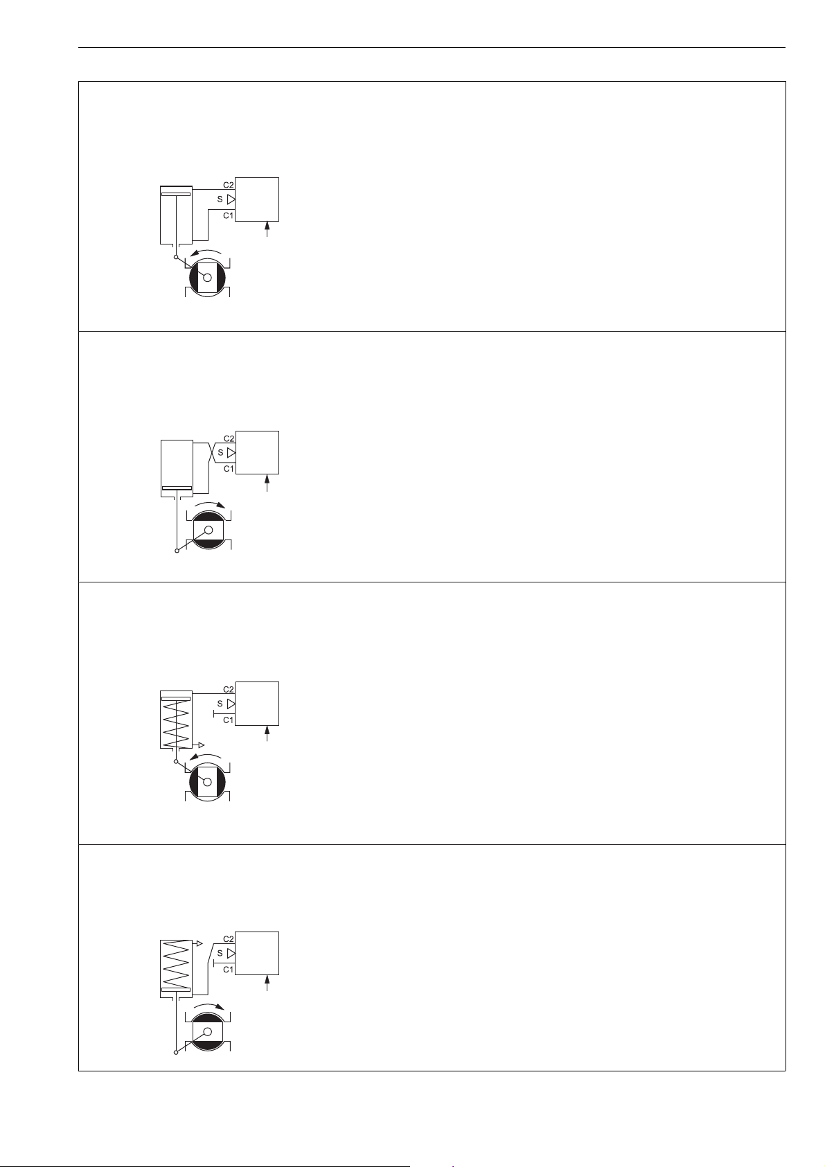
SINGLE-ACTING ACTUATOR, SPRING TO OPEN
SINGLE-ACTING ACTUATOR, SPRING TO CLOSE
DOUBLE-ACTING ACTUATOR, REVERSED PIPING
Increasing input signal to open valve (not recommended)
Default setting:
DIR = OPE
ROT = cC (close valve to clockwise)
ATYP = 2-A
PFA = OPE
A0, CUTL and VTYP according to valve type
5. Increasing input signal to open valve (shown)
Default setting:
DIR = OPE
ROT = cC (close valve to clockwise)
ATYP = 1-A
PFA = CLO (must be in the spring direction)
A0, CUTL and VTYP according to valve type
7. Increasing input signal to close valve (shown)
Default setting:
DIR = CLO
ROT = cC (close valve to clockwise)
ATYP = 1-A
PFA = OPE (must be in the spring direction)
A0, CUTL and VTYP according to valve type
6. Increasing input signal to close valve (not recommended)
Default setting:
DIR = CLO
ROT = cC (close valve to clockwise)
ATYP = 1-A
PFA = CLO (must be in the spring direction)
A0, CUTL and VTYP according to valve type
4. Increasing input signal to close valve (shown)
Default setting:
DIR = CLO
ROT = cC (close valve to clockwise)
ATYP = 2-A
PFA = OPE
A0, CUTL and VTYP according to valve type
.
3.
8. Increasing input signal to open valve (not recommended)
Default setting:
DIR = OPE
ROT = cC (close valve to clockwise)
ATYP = 1-A
PFA = OPE (must be in the spring direction)
A0, CUTL and VTYP according to valve type
DOUBLE-ACTING ACTUATOR
Increasing input signal to open valve (shown)
Default setting:
DIR = OPE
ROT = cC (close valve to clockwise)
ATYP = 2-A
PFA = CLO
A0, CUTL and VTYP according to valve type
2. Increasing input signal to close valve (not recommended)
Default setting:
DIR = CLO
ROT = cC (close valve to clockwise)
ATYP = 2-A
PFA = CLO
A0, CUTL and VTYP according to valve type
.
1.
7 ND90 71 en 15
SINGLE-ACTING ACTUATOR, SPRING TO OPEN
SINGLE-ACTING ACTUATOR, SPRING TO CLOSE
DOUBLE-ACTING ACTUATOR
Self closing
Default setting:
ROT = cC (close valve to clockwise)
ATYP = 2-A
PFA = CLO
A0, CUTL and VTYP according to valve type
3. Self closing
Default setting:
ROT = cC (close valve to clockwise)
ATYP = 1-A
PFA = CLO (must be in the spring direction)
A0, CUTL and VTYP according to valve type
4. Self opening
Default setting:
ROT = cC (close valve to clockwise)
ATYP = 1-A
PFA = OPE (must be in the spring direction)
A0, CUTL and VTYP according to valve t
ype
1.
DOUBLE-ACTING ACTUATOR, REVERSED PIPING
Self opening
Default setting:
ROT = cC (close valve to clockwise)
ATYP = 2-A
PFA = OPE
A0, CUTL and VTYP according to valve t
ype
2
.
Fig. 6 Operation directions and air connections, ND9000F and ND9000P
16 7 ND90 71 en
HART connection
position transmitter
connection (optional)
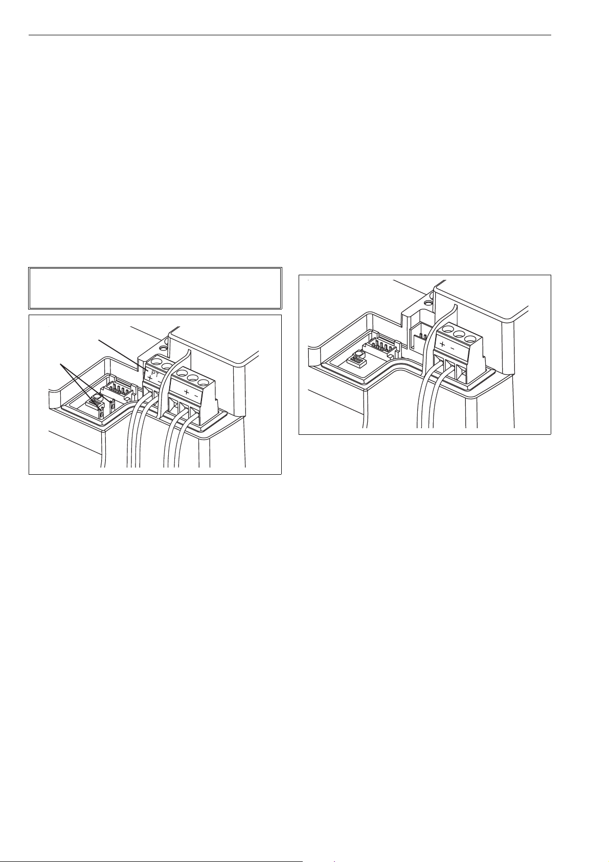
4.5 Electrical connections
ND9000H, ND7000H
The ND9000H and ND7000H is powered by a standard 4–20
mA current loop that also functions as a carrier to the HART
communication.
The input signal cable is led through a
M20 x 1.5 cable gland, or
1/2 NPT cable gland (U, E2)
Connect the conductors to the terminal strip as shown in
Fig. 9. It is recommended that the earthing of the input
cable shield be carried out from the DCS end only.
The position transmitter is connected to 2-pole terminal PT
as shown in Fig. 9. The position transmitter needs an external power supply. The ND9000H / ND7000H and the position transmitter circuits are galvanically isolated and
withstand a 600 V AC voltage.
NOTE:
The ND9000H and ND700H equal a load of 485 Ω in the
current loop.
ND9000F, ND9000P
The ND9000F is powered by F
OUNDATION fieldbus
(IEC 61158-2).
The ND9000P is powered by Profibus PA (IEC 61158-2).
The same bus cable is used also for the fieldbus communication.
The bus cable is led through a
M20 x 1.5 cable gland, or
1/2 NPT cable gland (U, E2)
Connect the conductors to the terminal strip as shown in
Fig. 10.
Reverse polarity protection permits connection of the bus
cables in any order.
The cable shield can be grounded by connecting the shield
to the earth connection screw. The shield can be left unconnected by using the empty terminal.
Fig. 7 Terminals, ND9000H and ND7000H
Fig. 8 Terminals, ND9000F and ND9000P
Please note following before mounting the cover of the
valve controller:
Attach the LUI (223) cabling to the sticker on the
reverse side of the LUI.
Check that the cabling does not get squeezed by the
electronics cover (39) or the device cover (100).
Check using a feeler gauge that the clearance
between the position indicator (109) and the electronics cover is 1 mm.
7 ND90 71 en 17
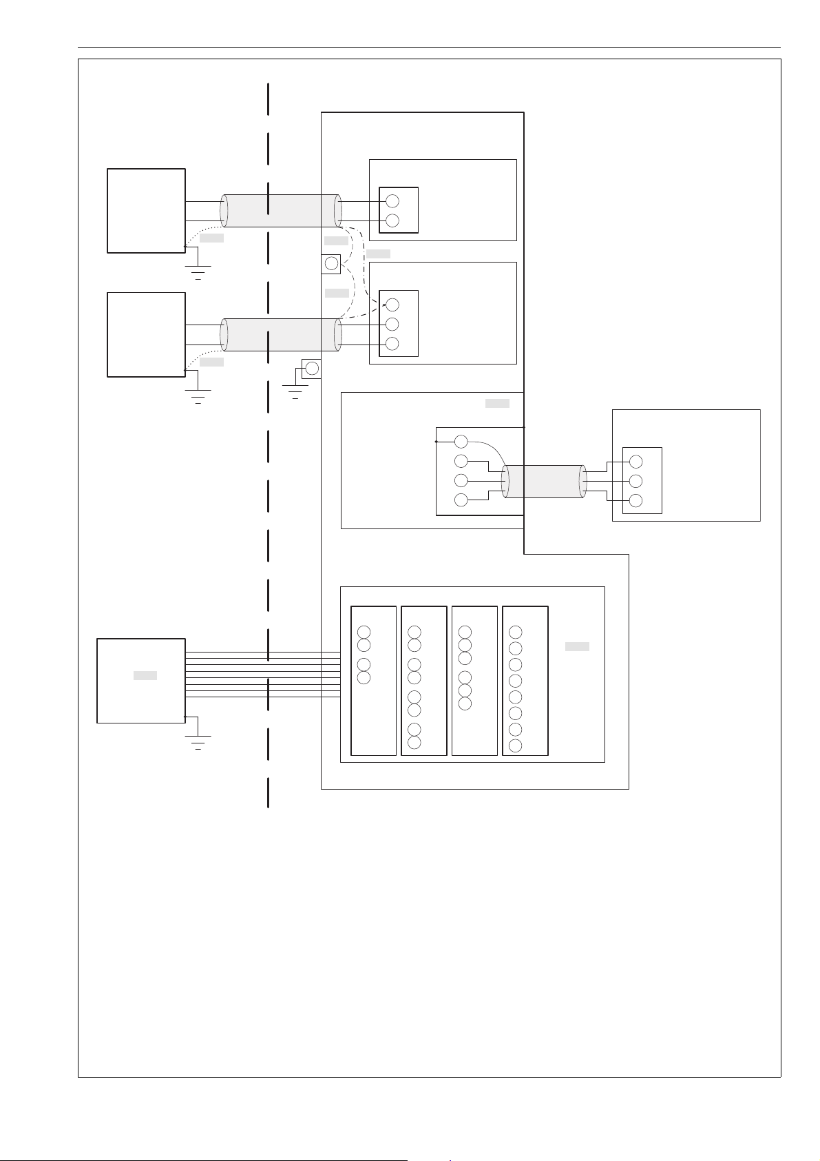
Notes
1. By default, the screen of the cable is connected to earth either at the barrier (dotted line) or at the earthing terminal inside ND9000H enclosure
(dash line). If the screen is connected to earth at both ends of the cable, the potential equalization of the system shall conform to requirements
of IEC 6007914:2013 Clause 16.2.3.
2. X102 terminal 1 (SHD) does not have any electrical connection. If wanted, cable screens can be connected to this terminal for floating
termination of screen at ND9000H end (dashdot line). Shrink tubes are recommended to avoid short circuits.
3. For installation in accordance with this figure, the intrinsically safe barrier must be certified by an accredited agency.
4. The following conditions must be satisfied:
Uo (Voc) <= Ui (Vmax) Co (Ca) >= Ci + Ccable
Io (Isc) <= Ii (Imax) Lo (La) >= Li + Lcable
Po <= Pi (Pmax)
5. Maximum nonhazardous area voltage must not exceed 250 V.
6. Canadian installations should be in accordance with Canadian Electrical Code, Part I. U.S. installations should be in accordance with Article 504
in the National Electrical Code, ANSI/NFPA 70.
7. See user manual for installation conditions.
8. See documents F41446 and F41476 for the approved switches and their entity parameters.
9. Remote Mount (option R) is only available for ND91_ (standard enclosure) variants.
NOITACOLSUODRAZAHNOITACOLSUODRAZAHNON
ND9000HValvePositioner
PositionTransmitter
ExiBarrier
Uo(Voc)≤28V
Io(Isc)≤120mA
Po≤1W
ExiBarrier
Uo(Voc)≤28V
Io(Isc)≤120mA
Po≤1W
NOTE1NOTE1
NOTE1
Earthing
terminal
(internal)
NOTE1
NOTE1
X300
1
2
NOTE2
X102
1
2
3
Ui(Vmax)=28V
Ii(Imax)=120mA
+
Pi(Pmax)=1W
Li=53uH
Ci=22nF
AnalogmAInput
SHD
Ui(Vmax)=28V
Ii(Imax)=120mA
+
Pi(Pmax)=1W
Li=53uH
Ci=22nF
ExiBarrier
NOTE8
Uo(Voc)≤Ui(Vmax)
Io(Isc)≤Ii(Imax)
Po≤Pi(Pmax)
Earthing
terminal
(external)
RemoteMount
PositionSensorInterface
Uo(Voc)=3.53V
Io(Isc)=12.6mA
Po=11.1mW
Lo(La)=10uH
Co(Ca)=10nF
SHD
+
CNT
LimitSwitches
I02,I09,
I57,I60
11
13
14
16
I41,I58
L
11
L+
L
L+
L
L+
12
L
13
L+
14
L
15
L+
16
17
L
L+
18
1
2
3
4
I45
11
12
13 L+
14
15
16 L+
NOTE9
RemoteMount
PositionSensor
1
Ui(Vmax)≥3.53V
+
Ii(Imax)≥12.6mA
CNT
2
Pi(Pmax)≥11.1mW
3
D44
L
L
(SOL1)
(SOL2)
(SOL
PWR1)
(SOL
PWR2)
TOP
SW+
TOP
SW
BTM
SW+
BTM
SW
NOTE8
Ui(Vmax)
Ii(Imax)
Pi(Pmax)
Li
Ci
Fig. 9 Control wiring, ND9000H and ND7000H, Ex i
18 7 ND90 71 en
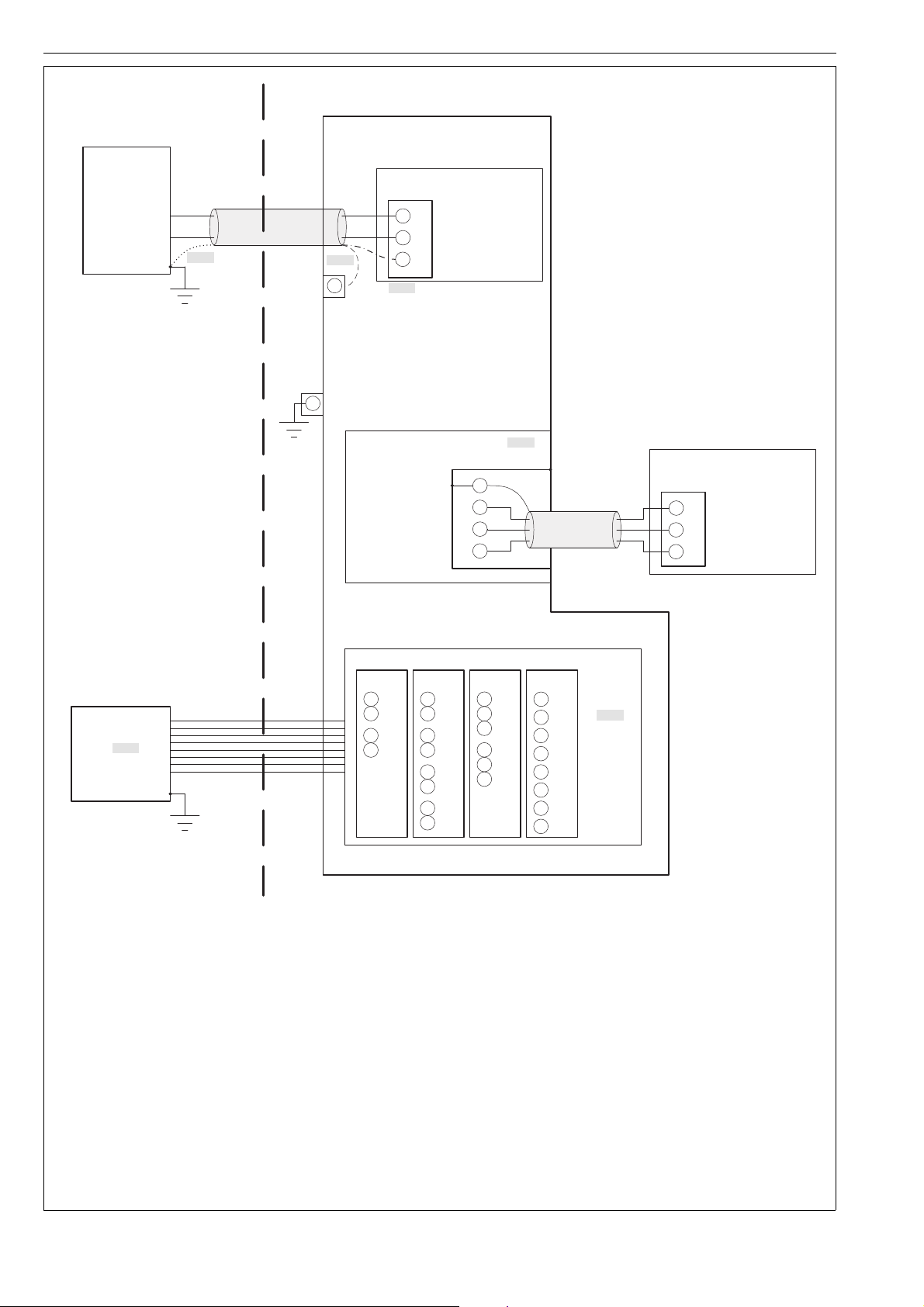
Notes
1. By default, the screen of the cable is connected to earth either at the barrier (dotted line) or at the earthing terminal inside ND9000F/P
enclosure (dash line). If the screen is connected to earth at both ends of the cable, the potential equalization of the system shall conform to
requirements of IEC 6007914:2013 Clause 16.2.3.
2. X102 terminal 3 (SHD) does not have any electrical connection. If wanted, cable screen can be connected to this terminal for floating
termination of screen at ND9000F/P end (dashdot line). Shrink tube is recommended to avoid short circuits.
3. For installation in accordance with this figure, the intrinsically safe barrier must be certified by an accredited agency.
4. The following conditions must be satisfied:
Uo (Voc) <= Ui (Vmax) Co (Ca) >= Ci + Ccable
Io (Isc) <= Ii (Imax) Lo (La) >= Li + Lcable
Po <= Pi (Pmax)
5. Maximum nonhazardous area voltage must not exceed 250 V.
6. Canadian installations should be in accordance with Canadian Electrical Code, Part I. U.S. installations should be in accordance with Article 504
in the National Electrical Code, ANSI/NFPA 70.
7. See user manual for installation conditions.
8. See documents F41446 and F41476 for the approved switches and their entity parameters.
9. Remote Mount (option R) is only available for ND91_ (standard enclosure) variants.
NOITACOLSUODRAZAHNOITACOLSUODRAZAHNON
FISCO’ia’
PowerSupply/
Barrier
Uo(Voc)≤24V
Io(Isc)≤380mA
Po≤5.32W
ND9000F/PValvePositioner
FieldbusInput
X102
Ui(Vmax)=24V
Ii(Imax)=380mA
Pi(Pmax)=5.32W
Li=10uH
Ci=5nF
1
2
+
3
SHD
Earthing
terminal
(internal)
Earthing
terminal
(external)
NOTE1NOTE1
NOTE1
LimitSwitches
Ui(Vmax)
Ii(Imax)
Pi(Pmax)
Li
Ci
ExiBarrier
Uo(Voc)≤Ui(Vmax)
Io(Isc)≤Ii(Imax)
Po≤Pi(Pmax)
11
13
14
16
L
L+
L
L+
12
L
11
13 L+
15
L
14
16 L+
I02,I09,
I57,I60
I45
NOTE8
NOTE8
NOTE2
(SOL1)
(SOL2)
(SOL
PWR1)
(SOL
PWR2)
TOP
SW+
TOP
SW
BTM
SW+
BTM
SW
D44
11
12
13
14
15
16
17
18
L
L+
L
L+
L
L+
L
L+
I41,I58
RemoteMount
PositionSensorInterface
Uo(Voc)=5.0V
Io(Isc)=17.8mA
Po=22.2mW
Lo(La)=10uH
Co(Ca)=10nF
SHD
+
CNT
1
2
3
4
RemoteMount
PositionSensor
Ui(Vmax)≥5.0V
Ii(Imax)≥17.8mA
Pi(Pmax)≥22.2mW
2
3
CNT
1
+
NOTE9
Fig. 10 Control wiring, ND9000F/P, Ex ’ia’ for Zone 0 / Division 1

7 ND90 71 en 19
NOITACOLSUODRAZAHNOITACOLSUODRAZAHNON
FISCO’ic’
PowerSupply/
Barrier
Uo(Voc)≤32V
Io(Isc)≤380mA
Po≤5.32W
ND9000F/PValvePositioner
FieldbusInput
X102
Ui(Vmax)=32V
Ii(Imax)=380mA
Pi(Pmax)=5.32W
Li=10uH
Ci=5nF
1
2
+
3
SHD
Earthing
terminal
(internal)
Earthing
terminal
(external)
NOTE1NOTE1
NOTE1
LimitSwitches
Ui(Vmax)
Ii(Imax)
Pi(Pmax)
Li
Ci
ExiBarrier
Uo(Voc)≤Ui(Vmax)
Io(Isc)≤Ii(Imax)
Po≤Pi(Pmax)
11
13
14
16
L
L+
L
L+
12
L
11
13 L+
15
L
14
16 L+
I02,I09,
I57,I60
I45
NOTE8
NOTE8
NOTE2
(SOL1)
(SOL2)
(SOL
PWR1)
(SOL
PWR2)
TOP
SW+
TOP
SW
BTM
SW+
BTM
SW
D44
11
12
13
14
15
16
17
18
L
L+
L
L+
L
L+
L
L+
I41,I58
RemoteMount
PositionSensorInterface
Uo(Voc)=5.0V
Io(Isc)=17.8mA
Po=22.2mW
Lo(La)=10uH
Co(Ca)=10nF
SHD
+
CNT
1
2
3
4
RemoteMount
PositionSensor
Ui(Vmax)≥5.0V
Ii(Imax)≥17.8mA
Pi(Pmax)≥22.2mW
2
3
CNT
1
+
NOTE9
Notes
1. By default, the screen of the cable is connected to earth either at the barrier (dotted line) or at the earthing terminal inside ND9000F/P
enclosure (dash line). If the screen is connected to earth at both ends of the cable, the potential equalization of the system shall conform to
requirements of IEC 6007914:2013 Clause 16.2.3.
2. X102 terminal 3 (SHD) does not have any electrical connection. If wanted, cable screen can be connected to this terminal for floating
termination of screen at ND9000F/P end (dashdot line). Shrink tube is recommended to avoid short circuits.
3. For installation in accordance with this figure, the intrinsically safe barrier must be certified by an accredited agency.
4. The following conditions must be satisfied:
Uo (Voc) <= Ui (Vmax) Co (Ca) >= Ci + Ccable
Io (Isc) <= Ii (Imax) Lo (La) >= Li + Lcable
Po <= Pi (Pmax)
5. Maximum nonhazardous area voltage must not exceed 250 V.
6. Canadian installations should be in accordance with Canadian Electrical Code, Part I. U.S. installations should be in accordance with Article 504
in the National Electrical Code, ANSI/NFPA 70.
7. See user manual for installation conditions.
8. See documents F41446 and F41476 for the approved switches and their entity parameters.
9. Remote Mount (option R) is only available for ND91_ (standard enclosure) variants.
Fig. 11 Control wiring, ND9000F/P, Ex ’ic’ for Zone 2 / Division 2

20 7 ND90 71 en
HAZARDOUS LOCATION
Control
system
Uout max 30 V
Control
system
Uout max 30 V
ND9200H_T
ND7200H_T
Position Transmitter
NONHAZARDOUS LOCATION
HAZARDOUS LOCATION
ND9200F
ND9200P
NONHAZARDOUS LOCATION
Entity Parameters:
Ui ≤ 32.0 V
Entity Parameters:
Uo ≤ Ui
connect the cable
shield to earth ground
Associated
apparatus
Fig. 12 Control wiring, ND9000 and ND7000, Ex d
Fig. 13 Control wiring, ND9000F and ND9000P, Ex d
7 ND90 71 en 21
4.5.1 Remote mounting
ND9100H,ND9100F, ND9100P, ND7100H
For applications if there is e.g. heavy vibrations, environment temperature is very high or access is difficult, there is
available remote position measurement option. In this kind
of applications position sensor is attached to actuator and
ND9000 can be installed further away. Pneumatic piping
between ND9000 and actuator is done as explained in
chapter 4.6 and wiring between position sensor and
ND9000 according to Fig. 13.
There are three different cable lengths available between
ND9000 and remote position sensor: 1.2m, 3m and 30m.
If position sensor is remote mounted to linear actuator,
there are some parameters which have to be defined as following:
valve acting type ( VTYP) have to be defined as rotary
valve rotation direction (ROT) have to be defined as
Clockwise to Close (CC)
Remote position sensor for rotary actuators is available also
with limit switch.
Fig. 14 Pin assignment in female connector view (connec-
tor in device)
Pin assignement
Pin# Function
1 Cable Shield Ground (Ground)
2 Potentiometer Plus (Blue)
3 Potentiometer Center (Brown)
4 Potentiometer Minus (Black)
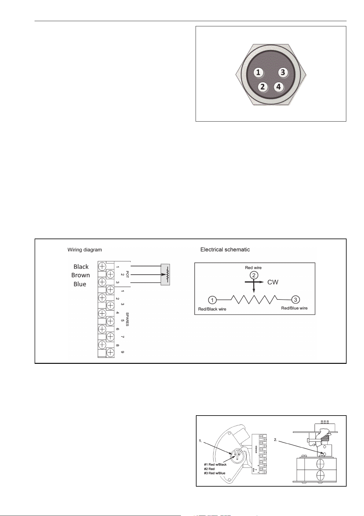
4.5.2 Quartz position sensor connections and calibration
Potentiometer Calibration
1. Operate the actuator to the desired “zero” position.
Connect an ohm meter across the terminals POT 1 &
POT 2 to measure the potentiometer output.
2. Loosen the bottom set screw and rotate the coupling
until the ohm meter reads approximately 5k Ohms
(assuming a 10K Ohm potentiometer). Retighten the
set screw and verify the ohm meter still reads
approximately 5k Ohms.
3. Operate the actuator to the desired “100 %” position
(assuming 90 degree rotation) and verify the ohm
meter reads (2.7K Ohms or 7.7K Ohms +/- 10 %,
depending on rotation direction).
4. Remove all test equipment.
5. Connect the position sensor cable to the terminal
strip as shown in the above wiring diagram.
6. Connect the connector end of the position sensor
cable to the ND9000 female connector shown in
Fig. 13.

22 7 ND90 71 en
Connection terminals in Rec adapter
4.5.3 Remote mounting by using Metso ReC
If there is 4-20mA output from the position sensor, that
can’t be connected directly to ND9100R. This kind of cases
there have to be ReC adapter which converts position signal suitable for ND9100 like shown in schematic picture
Connection terminals in Rec adapter:
NOTES:
1. Cut the ND9 cable (RC01, RC02 or RC03) and the
Position sensor cable to optimal length for your
application. Then connect the individual wires as
shown in connection diagram.
2. Connect positioner control (4…20mA) signal directly
to ND or alternatively to Pass through terminals IN+/
IN-, and Metso ND9 control input cable to OUT+/
OUT-.
• 4-20mA Pass Through connectors positive (+) ter-
minals are internally shorted, and negative (-) terminals are internally shorted.
3. Connector with “+24V” and “GND” shall be supplied
from external 24V (nominal 24 VDC, range is 18-30
VDC) voltage supply. This supply is powering the
converter and the external position sensor.
4. Use proper cable cland or blind plug for each cable
entry.

7 ND90 71 en 23
5 LOCAL USER INTERFACE (LUI)
The local user interface may be used to monitor the device
behaviour as well as configuring and commissioning the
controller during installation and normal operation. The
local user interface consists of 2 row LCD and 4 button keypad interface. There are also custom graphical characters
for special conditions.
Fig. 15 Local user interface (LUI)
5.1 Measurement monitoring
When the device is powered, it enters the measurement
monitoring view. The following measurements may be
viewed from the display. The Table 5 identify the default
unit and also optional unit of the measurement.
Table 6 Default / optional units of measurements
Measurement Default unit Optional unit
valve position Percentage
target position Percentage
current loop setpoint (ND9000H,
ND7000H)
setpoint
(ND9000F, P)
actuator pressure
difference
supply pressure bar psi
device
temperature
(of full scale)
(of full scale)
mA Percentage
Perce ntage
(of full scale)
bar psi
degree Celsius degree Fahrenheit
If the unit selection is altered from the FieldCare software to
US units, the pressure default unit will automatically be
changed to psi and temperature unit to Fahrenheit.
The active unit may be changed by pressing the ? key
constantly. The display shows the current unit selection on
the top row of the display. You may change the selection by
pressing + or - key while keeping the ? key pressed
down. When the buttons are released the current selection
will be activated.
If the device has been idle for 1 hour, and there is no user
activity on the local user interface, the measurements will
start scrolling on the display. This enables the user to view
all the measurements through the window of the main
cover.
Angle, where 0 % refers
to 0 deg.
none
(of full scale)
— continuous push
— brief push
Fig. 16 Measurement unit change, ND9000H and ND7000H
— continuous push
— brief push
Fig. 17 Measurement unit change, ND9000F and ND9000P

24 7 ND90 71 en
— brief push
5.2 Guided start-up
Guided startup offers a fast view of the most critical parameters of the ND controller, actuator and valve configuration.
After verifying the parameters the valve travel calibration is
recommended. The guided start-up is entered by pressing
the = and ? keys simultaneously.
The configuration parameters are listed in following order,
see explanation from 5.5:
Valve type VT YP
Actuator type ATYP
Positioner fail action PFA
Valve rotation direction ROT
Valve dead angle A0
PA address ADR (ND9000P only)
If you modify any of the parameters you will also need to
calibrate the device. See 5.6 for detailed description.
NOTE:
You may cancel any action by pressing the = button.
Cancelling of operation returns user interface view one
level up in menu hierarchy.
— brief push
Fig. 18 Guided start-up, ND9000H, ND7000H and ND9000F
Fig. 19 Guided start-up, ND9000P
5.3 Configuration menu
The local user interface is organised in a menu structure. To
enter the menus press + and - keys simultaneously in
the measurement monitoring view panel. To move to the
next or previous selection by pressing + or - key accordingly.
5.4 Mode menu
If the user wants to change the valve operating mode, press
the ? key at the MODE selection. The MODE will start to
flash and by pressing + or - key you may alter the operation mode selection. User accepts the current selection by
pressing the ? key.
There are two options for the operating mode.
5.4.1 AUTO
During the auto mode, the controller controls the valve
position according to the incoming setpoint signal from the
4–20 mA signal source or from the bus.

7 ND90 71 en 25
— brief push
HRTI
6
HRTI
6
HRTI
7
— brief push
Fig. 20 Configuration, ND9000H and ND7000H
5.4.2 MAN
During this mode the valve position may be controlled
manually by using the keypad and pressing the + or key. The position of the manually driven valve is not saved
in the memory of the controller, i.e. the valve will not return
to the same position after signal failure. However, the valve
may be driven back into position after signal failure by
using + and - keys. The manual control starts from the
current position of the valve after the MAN-mode is activated. In order to change the manual setpoint return to the
measurement monitoring view and go to target position
measurement. Press the ? key shortly to activate the target position editing, text TPOS starts to blink and now you
are able to edit the setpoint by pressing + or - key. The
setpoint changes in 0.1 % increments/decrements in spite
of the selected unit and the valve starts to move immediately. A continuous push changes the setpoint faster. In
order to view other measurements, press the ? or = key
and select a measurement. Repeat the previous steps if you
would like to alter the setpoint value again.
Fig. 21 Configuration, ND9000F

26 7 ND90 71 en
— brief push
5.5.1 Performance level, PERF
If you want to change the tuning of the valve position control, the PERF selection is available. The default factory
value is C.
Once PERF is displayed press the ? key to enter the
edit state and PERF starts to blink.
Select between five values by pressing the + or -
key.
Table 7 Performance level
Selection Meaning Description
A
b
C
d
E
For use with volume boosters and/or very fast actuators, additional
performance levels A1 to D1 can be used.
Characteristics of these extended levels are the same as those in the
table above. However, with performance level settings A1 to D1,
adaptive properties of the ND control algorithm are disabled.
Aggressive Immediate response to signal
Fast Fast response to signal changes,
Optimum Very small overshoot with
Stable No overshooting, slow response
Maximum stability No overshooting, deadband may
changes, overshoots
small overshooting
minimum step response time
to input signal changes
increase, slow but stable
behaviour
Fig. 22 Configuration, ND9000P
Fig. 23 Setpoint change in MAN mode
5.5 Configuration parameters
When PAR is on the display you may enter the configuration menu by pressing the ? key. In this menu the most
important configuration and signal modification parameters are viewable. You may view the current value and edit
them by pressing the ? key at the relevant parameter. The
name of the parameter will appear on the upper row of the
display and the current value is on the lower row.
After the desired value is displayed, press the ? key
to conclude the operation.
5.5.2 Low cut-off, CUTL
Low cut-off safety range CUTL ensures the valve closing
against mechanical travel stops. The factory default value is
2 %.
Once CUTL is displayed press the ? key to enter the
edit state and the CUTL will start to blink. The currently selected value appears as a percentage (%) on
the display
Modify the parameter value by pressing + or -
keys alternately until the desired value appears on
the display.
After the desired value is displayed, press the ? key
to conclude the operation.
5.5.3 Signal direction, DIR
ND9000H, ND7000H
The opening and closing direction of the valve with raising
current loop signal is defined by signal direction parameter
DIR.
When DIR is displayed press the ? key to enter the
edit state and DIR starts to blink.
Select either the OPE or CLO values by pressing the
+ and - keys. The value OPE signifies the raising
signal 4–20 mA to open the valve and CLO means
the raising signal to close the valve.
To conclude, press the ? key when the desired
value is shown on the display.
See default values in Fig. 7 and 8.
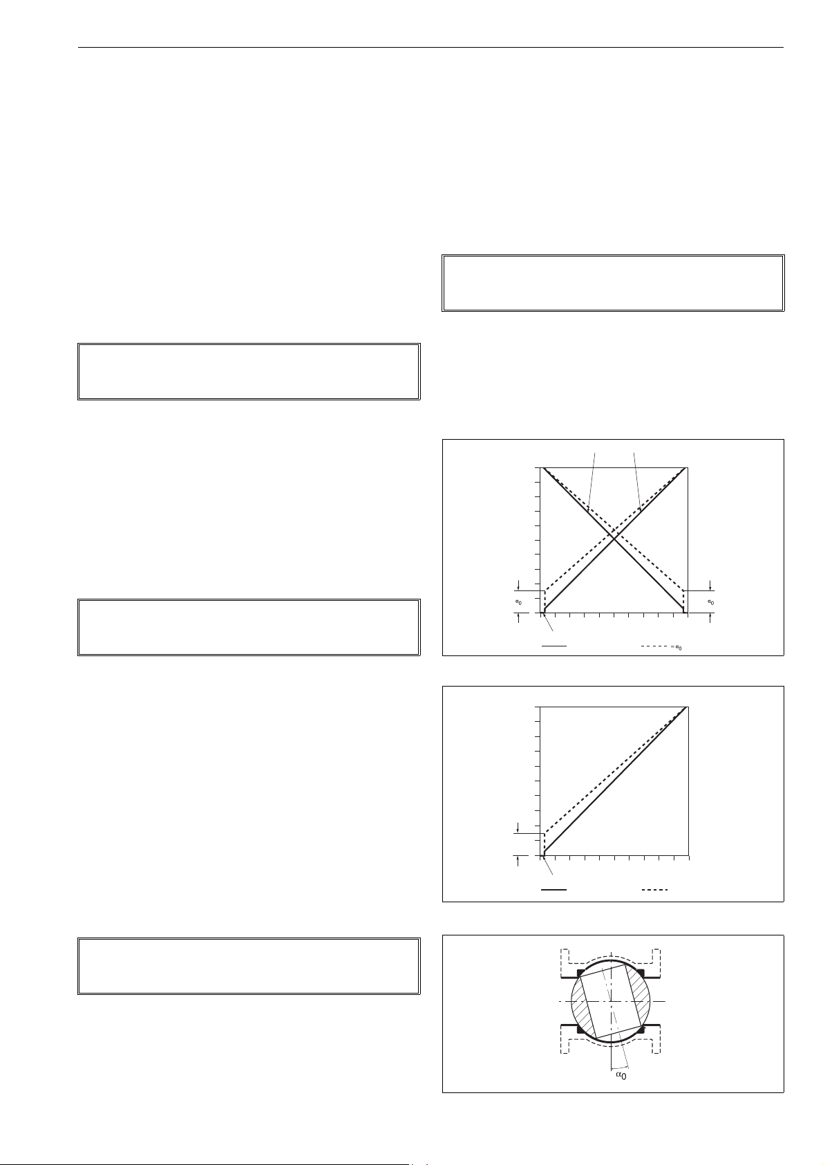
7 ND90 71 en 27
Increasing input signal closes valve Increasing input signal opens valve
cut-off safety range 2 ± 0.5 %
100
80
60
40
20
0
0 20 40 60 80 100
α
0
Position
Input signal
low cut-off safety range 2 ± 0.5 %
Basic setting
α
0
setting
5.5.4 Valve type, VTYP
To compensate for nonlinearity of the position feedback
caused by the actuator linkage mechanism of a linear control valve, the appropriate selection must be made on the
VTYP display.
After selecting VTYP on the display, press the ? key
to enter the edit state and the VTYP starts to blink.
Select between four values rot, LIn, nCG or FLI
using the + and - keys. The value rot indicates a
rotary valve and LIn a linear valve. Use nCG only for
nelesCV Globe valves to accommodate special linkage geometry. Use FLI only for linear valves when
linkage geometry is needed to be corrected by valve
controller.
To conclude press the ? key when the desired
value is shown on the display.
NOTE:
Perform valve calibration always when VTYP has been
changed.
5.5.5 Actuator type, ATYP
In order to optimise the control performance the device
needs to be informed about the actuator type.
After selecting ATYP on the display, press the ? key
to enter the edit state and ATYP starts to blink.
Select between two values 2-A or 1-A using the +
and - keys. The value 2-A indicates a double acting
actuator and 1-A a single acting actuator.
To conclude press the ? key when the desired
value is shown on the display.
5.5.7 Valve rotation direction, ROT
The application-specific parameter ROT defines the relationship between position sensor rotation and valve action.
Once ROT is displayed press the ? key to enter the
edit state and ROT starts to blink.
Now you may select between two values by pressing
the + or - key. The value cC indicates clockwise
rotation for closing the valve and ccC means counterclockwise to close.
After the desired value is displayed, press the ? key
to conclude the operation.
NOTE:
Perform valve calibration always when ROT has been
changed.
5.5.8 Valve dead angle, A0
The α0 setting is made for Metso segment and ball valves.
This setting takes into account the "dead angle" α
ball valves. The entire signal range is then used for effective
valve opening 90° - α
. Use 0 % as the "dead angle" for the
0
valves not mentioned in Table 7.
POSITION
100
80
60
40
20
of the
0
NOTE:
Perform valve calibration always when ATYP has been
changed.
5.5.6 Positioner fail action, PFA
Positioner fail action will take place in case of signal failure
or when the controller software discovers a fatal device failure. For single acting actuators set value in the spring direction. For double acting actuators see Fig. 7 and 8 for correct
settings.
Once PFA is displayed, press the ? key to enter the
edit state and the PFA will start blinking.
You may select between two values by pressing the
+ or - key. The CLO value indicates that the valve
ought to be closed in fail action situations. The OPE
value indicates the valve to be opened in fail action
situations.
After the desired value is displayed, press the ? key
to conclude the operation.
NOTE:
Perform valve calibration always when controller fail
action parameter has been changed.
0
020406080100
= Basic setting
INPUT SIGNAL
setting
Fig. 24 Principle of setting, ND9000H and ND7000H
Fig. 25 Principle of setting, ND9000F and ND9000P
Fig. 26 Dead angle

28 7 ND90 71 en
Table 8 Dead angle in percentage
Valv e
MBV
MBV
D,
size
QMBV
QMBV
1)
2)
mm in Dead angle, %
15 1/2 15
20 3/4 15
25 1 14 - - 25.5 19.5 - - 15 25.5 27 12.5
25/1 1/1 11
25/2 1/2 11
25/3 1/3 10
40 1 1/2 12 - - 24.5 12.5 - - 12 16 21 12.5
50 2 10 9 13.5 24.5 12.5 18 8 17 20.5 23 12.5
65 2 1/2 9 - - - - - - 13 - 18
80 3 10 8 12 18 8 16.5 8.5 9 8.5 15.5
100 4 10 8 12 16.5 8.5 16 9 8 7 14.5
125 5 12 - - - - 12 6.5 8 150 6 10 8 11.5 16 9 13.5 8 13.5 13
200 8 9 7 8.5 12 6.5 9.5 7 11.5
250 10 9 7 7.5 13.5 9.5 7 10.5
300 12 8 6 6.5 9.5 7.5 6 9.5
350 14 6 6 - 5 9.5
400 16 5 5.5
450 18 6
500 20 6 4.5
600 24 5.5
650 26 7
700 28 7
750 30 6
800 32 900 36 5.5
1) Seat supported 2) Trunnion 3) Soft seated R-valve 4) Low Cv Finetrol
T5,
P,
QT5
C
9.5
(14")
7.5
(16")
Valve series
QX-T5T25,
QT25
QXT25R,QR
ER-SOFT
59.5
3)FL4)
ZX
After selecting A0 on the display, press the ? key to
enter the edit state and A0 starts to blink. The value
currently selected appears as a percentage (%) on the
display.
Modify the parameter value by pressing + or -
keys alternately until the desired value appears on
the display.
Press the ? key to make your selection and return
to the setting state.
5.5.9 Profibus slave address setting
ND9000P only
You can modify the Profibus slave address by press-
ing + and - keys. Range is 0-126, default value is
126.
Press the ? key to make your selection and return
to the setting state.
5.5.10 Low cut-off, low limit, high cut-off, high
limit
ND supports signal cut-off and limiting in both ends of the
operating range. The configuration parameters are; low cutoff, low limit, high cut-off and high limit.
If the input signal is smaller than low cut-off, the
valve will be fully closed.
If the input signal is smaller than low limit, the valve
stays in the low limit.
If the input signal is greater than high cut-off, the
valve will be fully opened.
If the input signal is greater than high limit, the valve
stays in the high limit.
The cut-off overrides the limit as follows:
If the low cut-off > low limit, the low limit is not
active.
If the low cut-off < low limit, both low cut-off and
limit are active.
If the low cut-off is set to zero, the low cut-off is not
active.
If the high cut-off < high limit, the high limit is not
active.
If the high cut-off > high limit, both high cut-off and
limit are active.
If the high cut-off is set to 100 %, the high cut-off is
not active.
Only the low cut-off is adjustable using the LUI. Low limit,
high cut-off and high limit are configurable via FieldCare
software.
5.5.11 HART version
Select if device is used as HART 6 or HART 7 device
by using the + and - keys.
To conclude press the [enter] key when the desired
value is shown on the display.
As default device is HART 6 device.
Device needs to be rebooted after change
5.5.12 Language selection, LANG
Select between three languages EnG, GEr or FrE
using the + and - keys.
To conclude press the ? key when the desired
value is shown on the display.
5.6 Valve travel calibration
During the calibration the ND controller searches for optimum internal control parameters for the valve position control. Also it defines open and close ends. After the
calibration sequence is finished, press the = key to get
back to the measurement view.
You may interrupt the calibration sequences at any time by
pressing the = key, then device returns to basic measurement display. Calibration parameters will not be changed if
calibration is cancelled or failed. If calibration fails, LUI and
DTM event log shows error message. See Chapter 7 for
more information. The calibration will not alter the PERF
parameter.
Select CAL from the menu by using + or - keys and press
the ? key. Define the calibration type AUTO, MAN,
1PT CAL, LCAL 3P or LCAL 9P, see Fig. 27. In case of
LCAL 3P and LCAL 9P, see more information from 5.6.4.
When CAL menu from the LUI is opened again, the last
started travel calibration will be shown first on the list.
NOTE:
If AUTO CAL, MAN CAL, LCAL 3P or LCAL 9P is selected,
the valve controller must be in AUTO mode. 1-point calibration may run in both AUTO and MAN mode.
WAR NIN G:
Automatic calibration drives the valve against the
mechanical open and closed travel limits of the valveactuator assembly. Make sure that these procedures
can be safely executed.
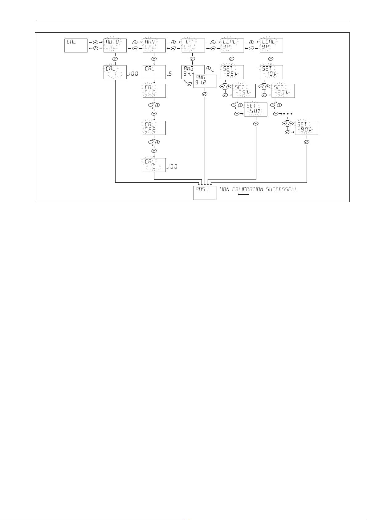
7 ND90 71 en 29
Fig. 27 Calibration selection
5.6.1 AUTO calibration function
During the calibration process the display will show blinking CAL and numbers run from 1 to 100 to show calibration
progress. After calibration the display shows scrolling
POSITION CALIBRATION SUCCESSFUL text and device
returns to basic measurement display after one hour. Press
the = key to get back to the basic measurement view
immediately.
If you cannot drive the valve into a fully open position or if
there is no mechanical limit stop, a manual calibration is
required.
If AUTO CAL option is not available in the menu, please
check Section 5.6.2
5.6.2 MAN calibration function
After selecting the MAN calibration function from the menu
press the ? key to activate the procedure. First there will
be short valve speed identification. Then user is asked to
drive valve manually into open or close end (depends on
installation), the display shows CAL OPE or CAL CLO. With
the + or - keys drive the valve manually to the open
(100 %) or closed (0%) position and then press the ? key.
After defining first end position, user is asked to drive valve
to another end position. Display shows CAL OPE or
CAL CLO (depends on installation). With the + or - keys
drive the valve manually to the open (100 %) or closed (0%)
position and then press the ? key.
The display shows blinking CAL and numbers continue to
run from 10 to 100 to show the calibration progress. After
calibration the display shows scrolling
POSITION CALIBRATION SUCCESSFUL text and device
returns to basic measurement display after one hour. Press
the = key to get back to the basic measurement view
immediately.
If the last performed calibration has been MAN, and valve
type is selected as LIn or FLI, it is not possible to run AUTO
calibration. AUTO CAL is disabled from the calibration
menu.
Only way to get AUTO CAL back to the calibration menu is
to select valve type as rot again, then there are all calibration options available again.
5.6.3 1-Point calibration
1-point calibration is useful in cases in which the valve controller needs to be changed but it is not possible to run the normal
calibration and the valve is not allowed to change position (the
valve is active, for example). This procedure does not ensure
the best possible control performance, and it is always recommended to run either AUTO or MAN calibration, as
soon as possible. The primary way to calibrate valve position
is to use either AUTO or MAN calibration.
Before starting 1-point calibration, read the warnings and
notes below and check that the valve is mechanically
locked. Before starting 1-point calibration, adjust the
TPOS value in the MAN mode (see Section 5.4.2) to correspond with the physical position of the valve.
Once the 1-point calibration is started, the first view shows
ANG above and NN.N below (see Fig. 27). NN.N presents the
maximum turning angle (in degrees) that the valve can perform.
To ch a n g e the value:
Press ?, NN.N begins blink
Press + and - keys to change the value
After the correct valve operation angle is set, press ? key.
After calibration the ND9000 and ND7000 scrolls
POSITION CALIBRATION SUCCESSFUL text. You may interrupt the calibration sequences at any time by pressing the
= key.

30 7 ND90 71 en
After the calibration sequence is finished, press the = key
twice to get back to the measurement view.
Please refer to Chapter 7 if this sequence has failed and an
error message is displayed.
The valve can now be unlocked.
WAR NIN G:
Supply pressure can be connected to the valve controller only after 1-point calibration is successfully
completed. If supply pressure is connected to the
valve controller before successful 1-point calibration,
the valve may move and cause danger.
NOTE:
If an incorrect valve operation angle is given to the valve
controller during 1-point calibration, valve operation will
be incorrect. In this case, you must perform 1-point calibration again with correct valve operation angle value.
NOTE:
If the valve position is not stable (due to heavy vibration
etc) during 1-point calibration, the calibration will not end
successfully. Check that the valve position is fully stable
during this operation.
5.6.4 Linearization
Linearization FLI can be used for linear valves when linkage
geometry is needed to be corrected by valve controller.
Linearization can be done with 3 points (and end points) or
with 9 points (and end points).
3-point linearization will be done in positions 25 %, 50 %
and 75 %.
9-point linearization will be done in positions 10 %, 20 %,
30 %, 40 %, 50 %, 60 %, 70 %, 80 % and 90 %.
User can terminate linearization any time by press-
ing the = key. Linearization is cancelled and device
returns to basic measurement display. No changes to
linearization are made and corresponding message
is shown to user.
If linearization fails, a message about the reason will be
shown on the LUI display and also in event log that can be
read with DTM. If linearization is not successfully completed, there will be no changes in linearization.
5.6.5 LS status
ND9000F and ND9000P only
LS shows the status of limit switches:
--- No LS active
CLO LS "Closed" active
OPE LS "Open" active
LSE LS Error, both switches activated
at the same time
5.7 Special displays
5.7.1 User interface locked
In order to prevent unauthorised access, the Local User
Interface may be locked. In this mode measurements may
be viewed but configurations and calibrations are prohibited. You may lock and unlock the device only via HART
(ND9000H, ND7000H) or dip switch (ND9000F, ND9000P),
see Fig. 32 and 33. When the Local User Interface is locked
the lock symbol will be activated on the display.
NOTE:
There have to be external position measurement in linear
valve that you can compare actual position and given
position.
Before linearization:
Perform the Valve travel calibration (auto or manual).
Before 3-point or 9-point linearization is visible on
the display. Valve type VTYP has to be set as Fixed
Linear FLI.
Linearization:
Select 3-point LCAL 3P or 9-point LCAL 9P lineari-
zation from CAL by pressing the ? key.
The display shows SET 10 % or SET 25 % depend-
ing on which is selected: 3-point or 9-point calibration.
Drive valve position manually with the + and -
keys to 10 % or 25 %.
When required position is reached (according to
position measured by external measurement) press
the ? key.
The display starts to blink next position (50 % or
20 %). When last point have confirmed, the LUI dis-
plays that calibration is successful and returns to
basic measurement display.
Fig. 28 LUI locked
5.7.2 Online-alarm active
If an online alarm has been detected the solid & symbol is
activated. This symbol will disappear after the recovery
from online alarm. You may view the reason for the alarm
by viewing the latest event while pushing the = and keys simultaneously or by using FieldCare software where
all events may be viewed.
scrolling text
Fig. 29 Example of online alarm message

7 ND90 71 en 31
scrolling text
5.7.3 Viewing of latest event
You may view the latest event by pressing the = and keys simultaneously in the measurement monitoring view.
The message is scrolled on the top row of the display twice.
You may stop the scrolling by pressing the ? key. By
pressing the = key, the message will disappear.
For the list of events see Chapter 7.
5.7.4 Fail-safe active
When the ND detects serious device failure (setpoint, valve
position and control signals) it enters fail-safe mode, which
drives the control valve into the position defined in the
parameter controller fail action (PFA). Fail-safe mode is indicated by the display as seen in Fig. 30. The error message is
displayed until the cause of error is eliminated and the ND
unit is restarted, i.e. the power is momentarily disconnected.
Write protection, ND9000F, ND9000P
The ND9000F/ND9000P is delivered from the factory with
HW write protection OFF as the default setting. Reading
and changing parameters is thus allowed.
Write protection can be enabled with the switch (DIP1)
located on the circuit board, Fig. 34.
The simulation can be enabled with the switch (DIP2)
located on the circuit board, Fig. 34.
Write protection protects all write access to all writeable
parameters of the device. Changing the parameters from
the LUI or fieldbus configurator is thus not allowed.
The simulation switch is OFF as the default setting. A0 block
simulation is thus disabled. The simulation can be enabled
with the switch (DIP2) located on the circuit board, Fig. 34.
ON
12
Fig. 30 Example of failsafe display
5.7.5 Reduced performance
When the ND detects spool valve measurement failure, it
enters reduced performance mode. This is indicated by the
blinking & in the display, see Fig. 31.
In reduced performance mode valve control can not be
optimized. To correct the problem replace the spool valve
assembly and perform auto calibration.
Fig. 31 Reduced performance display
5.8 Write protection
HART write protection, ND9000H and ND7000H
The ND9000H and ND7000H are delivered from the factory
with the default set as HART write protection OFF. Reading
and changing parameters is allowed. HART protection may
be enabled with a switch (DIP1) located on the communication circuit board under the Local User Interface module.
Changes that may influence the valve position cannot be
made using the FieldCare software or HART hand held
when switch no. 1 (on the left-hand side of the switch
block) is ON, Fig. 33.
Fig. 32 HART write protection, ND9000H and ND7000H
12
ON
Fig. 33 Write protection, ND9000F and ND9000P

32 7 ND90 71 en
6 MAINTENANCE
Ex d WARNING (ND9200, ND7200, ND9300):
Service of the cylindrical flameproof joints is not
allowed.
This includes the diaphragm cover (part 171), flame arrester
plunger (part 200), their mating surfaces in the housing
(part 2) and the shaft assembly fixed in the housing.
The maintenance requirements of the ND valve controller
depend on the service conditions, for instance, the quality
of instrument air. Under normal service conditions there is
no requirement for regular maintenance.
When maintaining the ND ensure that the supply air is shut
off and pressure is released. In the following text the numbers in brackets ( ) correspond to the part numbers in the
exploded view as shown in Chapter 12, unless otherwise
stated.
The ND valve controller includes the following interchangeable modules: prestage unit (120), spool valve (193), communication circuit board with optional position transmitter
(215).
In ND9100 and ND7100 the modules are located below the
covers (39) and (43). In ND9200, ND7200 and ND9300 the
spool valve is located on the bottom side of the device
while the other modules are located below the covers (100)
and (39). In the event of failure the whole module must be
changed. The module retrofit must be assembled in a clean,
dry environment. In reassembly apply a thread-locking
compound (for instance, Loctite 243) and tighten the
screws firmly.
6.1 Prestage
6.1.2 Installation
ND9100, ND9400 and ND7100
Place a new O-ring (140) into the groove on the
spool valve and press the prestage into place. Make
sure the nozzle is guided into the O-ring properly.
The screws guide the prestage body into the correct
position. Tighten the screws (139) evenly.
Push the prestage 2-pole wire connector into the
socket on the spool sensor board. The wire connector may only be fitted in the correct position. Replace
the prestage cover (43) and tighten the M4 screw
(44).
ND9200, ND7200, ND9300
Place a new O-ring (140) into the groove in the hous-
ing and press the prestage into place. Make sure the
nozzle is guided into the O-ring properly. The screws
guide the prestage body into the correct position.
Tighten the screws (139) evenly.
Push the prestage 2-pole wire connector into the
socket on the spool sensor board. The wire connector can only be fitted in the correct position. Replace
the inner cover (39) and tighten the M3 screws.
6.2 Spool valve
6.2.1 Removal
NOTE:
Each spool valve body has an individual corresponding
spool which cannot be replaced by any other spool. Never
alter the orientation of the spool. The orientation of the
spool is marked on the device, see Fig. 34 and 35.
NOTE:
The prestage must be handled carefully. In particular the
moving parts of the prestage should not be touched
when the inner cover (39) is not in place.
6.1.1 Removal
ND9100, ND9400 and ND7100
Open the prestage cover (43) attached with M4
screw (44). Unplug the prestage wire connector on
the spool sensor board. Unscrew the M4 screws (139,
2 pcs.) and lift up the prestage module. Remove the
O-ring (140).
ND9200, ND7200, ND9300
Loosen the M8 stop screw (110) in the position indi-
cator (109) and turn the position indicator from the
shaft (11). Remove the inner cover (39) attached with
M3 screws (42, 3 pcs).
Unplug the prestage wire connector from the spool
sensor board (182). Unscrew the M4 screws (139, 2
pcs.) and lift up the prestage module. Remove the Oring (140).
ND9100, ND9400 and ND7100
Before removing the spool valve assembly (193) the
prestage (120) must be removed. See 6.1.
Unscrew the M4 screws (47, 3 pcs.), M3 screws (48, 2
pcs.) and M3 screw (49). Remove the spool valve
assembly.
The spool valve may be cleaned if special attention is
paid to a clean environment and proper procedure.
After unscrewing the M4 screws (47, 3 pcs.) the spool
valve may be lifted from the fixture. Hold the ends of
the body with your fingers to avoid dropping the
spool from the body. Clean the spool and the bore of
the body with care. Do not leave any fibres from
cleaning materials in the bore or on the spool. Do
not scratch the mating surfaces of the spool and
body. The restrictor is located under the spool valve
in the fixture. It may be cleaned when the spool
valve is removed.
ND9200, ND7200, ND9300
For spool valve removal it is usually necessary to unmount
the valve controller from the actuator.
Working from the bottom side of the valve control-
ler, unscrew the M4 screws (47, 3 pcs.). Remove the
spool valve cover (61) and the spool valve (193) with
gasket (174). Hold the ends of the body with your
fingers to avoid dropping the spool from the body.

7 ND90 71 en 33
195 194140 160 174 175
0327000170
Assembly direction of spool
Sticker on fastener (160)
195 174 194
63 61
Sticker
Spool valve removal is only possible in the spring-
forced failsafe position of the spool. In the case of a
stuck spool it might be necessary to remove the secondary diaphragm cover (167), the spool spring
(166) with its disc (164) and the secondary diaphragm (162) with its plate. After the removal of
these parts it is possible to use a punch to force the
spool to the failsafe position.
The spool valve may be cleaned if special attention is
paid to a clean environment and proper procedure.
Clean the spool and the bore of the body with care.
Do not leave any fibres from cleaning materials in
the bore or on the spool. Do not scratch the mating
surfaces of the spool and body.
6.2.2 Installation
NOTE:
If the maintenance operations have been done for the
spool valve assembly, the device must always be cali-
brated.
ND9100, ND7100
Ensure that the gasket (174) is properly located in
the groove on the bottom of the spool valve assembly. Mount the spool valve assembly on to the housing and tighten the M3 and M4 screws evenly.
Ensure the O-ring (140) slots inside the groove fully.
Mount the prestage unit directly on the spool valve
unit as in 6.1.
Fig. 34 Spool valve assembly, ND9100 and ND7100
ND9200, ND7200, ND9300
Ensure that the gaskets (174) and (63) are properly
located in their grooves on the bottom of the housing. Mount the spool valve and the spool valve cover
(61) to the housing, and tighten M4 screws evenly.
6.3 Flame arrestor assembly
ND9200, ND7200, ND9300
The flame arrestor and the restrictor are fit into the same
plug which is located under the diaphragm cover (171). This
assembly can not be disassembled and should be replaced
if clogged.
To remove the flame arrestor assembly, unscrew the
screws (173, 4 pcs.) and remove the diaphragm cover
(171) with its O-ring. Turn a M3 screw into the
threaded hole of the flame arrestor assembly to
extract it from the housing. Installation is the reversal of removal. Place the O-rings carefully.
Fig. 35 Spool valve assembly, ND9200, ND7200
and ND9300
6.4 Diaphragms
ND9200, ND7200, ND9300
The diaphragms (169, 162) may be replaced by removing
the respective covers (171, 167). The unit should be
unmounted from the actuator and the side to be worked on
turned upwards in order to avoid loss of small parts. When
replacing the secondary diaphragm (162), the spool spring
(166) with its guide (164) has to be removed first. When
reassembling, pay special attention to the installation of the
diaphragms and O-rings.
6.5 Communication board
6.5.1 Removal
NOTE:
Ground yourself on the body of the device before touching the circuit board.
NOTE:
Do not remove the Valve Controller Board (210)!
Removing the board will void the warranty.
ND9100, ND7100
Loosen the M8 grub screw (110) off the position indi-
cator (109) and turn the position indicator from the
shaft. Remove the cover of the prestage (43).
Remove the electronics cover (39) attached with M3
screws (42, 4 pcs.).
Remove the M3 screws (217, 4 pcs.). Hold the sides of
the circuit board and lift it directly upwards and outwards. Handle the board carefully, touching only the
sides.
ND9200, ND7200, ND9300
Loosen the M8 stop screw (110) in the position indi-
cator (109) and turn the position indicator from the
shaft (11). Remove the inner cover (39) attached with
M3 screws (42, 3 pcs.).
Remove the M3 screws (217, 4 pcs.). Hold the sides of
the circuit board and lift it directly upwards and outwards. Handle the board carefully, touching only the
sides.

34 7 ND90 71 en
215
6.5.2 Installation
Ex WARNING:
Grounding of the circuit board is essential to explosion protection.
The board is grounded to the housing by the mounting
screw next to the terminal blocks.
ND9100, ND7100
Mount the new communication circuit board care-
fully.
Locate the pins with the matching connector on the
board. Tighten the M3 screws (217) evenly.
Install the electronics cover (39)s and the cover of
the prestage (43).
Mount the position indicator (109) on the shaft and
tighten the M8 screw (110) temporarily. The final orientation and locking of the position indicator should
be done after installation of the valve controller to
the actuator.
ND9200, ND7200, ND9300
Mount the new communication circuit board care-
fully.
Locate the pins with the matching connector on the
board. Tighten the M3 screws (217) evenly.
Install the inner cover (39).
Mount the position indicator (109) on the shaft and
tighten the M8 stop screw (110) temporarily. The
final orientation and locking of the position indicator
should be done after installation of the valve controller to the actuator.
215
Fig. 36 Communication board, ND9000H and ND7000H
Fig. 37 Communication board, ND9000F and ND9000P
7 ERROR MESSAGES
7.1 Failsafe errors
Display message Description
POSITION SENSOR FAILURE Position sensor measurement failed.
SETPOINT SENSOR FAILURE
(HART version only)
PRESTAGE SHORTCUT ERROR Shortcut in the prestage unit.
FAE nnn Fatal malfunction in the device.
Change the ND device to a new one.
mA measurement failed. Change
the ND device to a new one.
nnn is a number between 001– 004.
Change the ND device to a new one.
7.2 Alarms
Display message Description
DEVIATION ALARM Valve deviation out of limits.
STICTION LOW ALARM Stiction has exceeded the low limit
STICTION HIGH ALARM Stiction has exceeded the high
LOAD FOR OPENING LOW ALARM Load for opening has exceeded the
LOAD FOR OPENING HIGH ALARM Load for opening has exceeded the
SPOOL VALVE PROBLEM Spool valve problem in the
PNEUMATICS PROBLEM Inconsistent actuator pressures.
FRICTION PROBLEM Valve is not moving correctly.
(ND9000 only).
limit (ND9000 only).
low limit (ND9000 only).
high limit (ND9000 only).
controller. Check the spool valve
unit and replace if necessary.
Check pneumatic connections and
actuator leakage.
Check load factor.
7.3 Errors
Display message Description
PRESTAGE CUT ERROR Prestage wire is cut or connector is
PRESSURE SENSOR 1 FAILURE Actuator pressure sensor has failed.
PRESSURE SENSOR 2 FAILURE Actuator pressure sensor has failed.
PRESSURE SENSOR 3 FAILURE Supply pressure sensor has failed.
SPOOL VALVE SENSOR FAILURE Spool valve sensor failed. Check
TEMPERATURE SENSOR FAILURE Temperature measurement failed.
STATISTICS DATABASE ERROR Failed to store statistics. New
EVENT DATABASE ERROR Failed to store events. The new
loose.
The device performance level is
reduced if device is used as D/A
actuator. This will not effect to
control performance for single
acting actuator. Change the ND
device to a new one during next
maintenance activity.
The device performance level is
reduced. Change the ND device to
a new one during next
maintenance activity.
This does not affect the
performance level.
the sensor connections. The device
performance level is reduced. For
ND9100 and ND7100 change spool
valve assembly (193) during next
maintenance activity. For ND9200/
ND7200/ND9300 replace device to
a new one during next
maintenance activity.
The accuracy of the measurements
is reduced. Change the ND device
to a new one during next
maintenance activity.
measurements will be lost.
events will be lost.

7 ND90 71 en 35
POSITION CALIBRATION FAILED Travel calibration failed. Check the
POSITION CHANGE TOO SMALL Given samples in Linearization are
LINEARIZATION FAILED 3P/9P linearisation failed.
FACTORY SETTINGS RESTORE FAIL Factory settings restoring failed.
TOO SMALL VALVE MOVEMENT Position sensor range failed during
POSITIONER SHAFT MOVEMENT
OUT OF RANGE
CALIBRATION TIMEOUT Calibration timeout occurred.
CALIBRATION START FAILED The calibration starting conditions
TOO SMALL SPOOL VALVE
MOVEMENT
POOR VALVE PACKAGE
CONTROLLABILITY
CHECK ASSEMBLY RELATED
PARAMETERS
CA LIBRATI ON FAIL - SUPP LY
PRESSURE OUT OF RANGE
CALIBRATION FAIL - SENSOR
FA ILU R E
CALIBRATION FAIL - POSITION OUT
OF RANGE
configuration parameters and
controller mounting. Check that
the controller shaft is correctly
aligned.
closer than 5 % to each other, i.e.
there's not enough change
between two consequent samples.
calibration. Valve controller shaft
failed to rotate minimum 45
degrees. Check the configuration
parameters and controller
mounting. Check that the
controller shaft is correctly aligned.
Pointer out of mark on housing, see
Figure 6.
Check configuration and
installation.
are not met. Check the supply
pressure.
Spool sensor range failed during
position calibration. Check the
configuration parameters. Check
the prestage and spool valve unit.
Position calibration takes too long
time due to weak controllability.
Check assembly and assembly
related parameters and start
calibration again.
Supply pressure out of range
during position calibration.
Sensor failure (valve position/spool
position) is detected during
position calibration.
Valve position out of range is
detected during position
calibration.
7.4 Warnings
Display message Description
TOTAL OPERATION TIME WARNING Operating time exceeded limit.
VALVE FULL STROKES WARNING Valve stroke counter limit reached.
VALVE REVERSALS WARNING Valve reversals counter limit
ACTUATOR FULL STROKES
WAR NIN G
ACTUATOR REVERSALS WARNING Actuator reversals counter limit
SPOOL FULL STROKES WARNING Spool stroke counter limit reached.
SPOOL REVERSALS WARNING Spool reversals counter limit
STEADY STATE DEVIATION
WAR NIN G
DYNAMIC STATE DEVIATION
WAR NIN G
STICTION LOW WARNING Warning that stiction has exceeded
STICTION HIGH WARNING Warning that stiction has exceeded
LOAD FOR OPENING TOO LOW Warning that load for opening has
LOAD FOR OPENING TOO HIGH Warning that load for opening has
SUPPLY PRESSURE OUT OF LIMITS Supply pressure has exceeded the
TEMPERATURE OUT OF LIMITS Temperature has exceeded the
HUNTING DETECTION WARNING Valve hunting detected. Change
REDUCED PERFORMANCE
ACTIVATED
TOO LOW SUPPLY PRESS FOR 1ACT ACTUATOR
VALVE REVERSALS TREND
WAR NIN G
SETPOINT REVERSALS TREND
WAR NIN G
VALVE TRAVEL TREND WARNING Warning that valve travel per day
VALVE REVERSALS WH STABLE SETP
WAR NIN G
reached.
Actuator stroke counter limit
reached.
reached.
reached.
Warning that steady state
deviation has increased.
Warning that dynamic state
deviation has increased (ND9000
only).
the low limit (ND9000 only).
the high limit (ND9000 only).
exceeded the low limit (ND9000
only).
exceeded the high limit (ND9000
only).
specified operating conditions.
specified operating conditions.
performance level to less
aggressive to stabilize valve. Check
that the spool valve capacity is
suitable for the actuator.
Valve controller performance is
reduced due to defective spool
valve sensor or defective pressure
sensor.
Too low supply pressure level for 1acting actuator.
Warning that valve reversals per
day has exceeded the limit.
Warning that setpoint reversals per
day has exceeded the limit.
has exceeded the limit.
Warning that valve reversals while
setpoint is stable, per day, has
exceeded the limit

36 7 ND90 71 en
7.5 Notifications 8 TROUBLE SHOOTING
Display message Description
POSITION CALIBRATION
SUCCESSFUL
LINEARIZATION SUCCESSFUL 3P/9P linearisation successfully
TEST CANCELLED Off-line test has been cancelled.
TEST DONE Off-line test has been successfully
TEST FAILED Off-line test failed. Repeat the test
CALIBRATION CANCELLED Calibration has been cancelled.
FACTORY DEFAULTS ACTIVATED Factory settings activated. Device
PT NOT ACTIVATED (Only with position transmitter
1PT CAL FAILED 1-point calibration failed. Check
REDUCED PERFORMANCE
DEACTIVATED
Position calibration successfully
performed.
performed.
performed.
sequence.
have to be configured and
calibrated.
option).
The position transmitter is not
energized.
the mounting of the valve
controller. Verify input parameter
(range) value. Check rotation
parameter (ROT).
Spool valve measurement and
normal valve control is recovered.
Mechanical/electrical defects
1. A change in the valve position setpoint will not affect the
position of the actuator
Supply pressure too low
Spool valve sticks
Incorrect configuration parameters
Actuator and/or valve jammed
Signal wires incorrectly connected, no value on dis-
play
Circuit boards are defective
Calibration has not been carried out
Device is in manual mode
Prestage is defective
Device is in fail-safe mode
Spool mounted backwards into spool valve
2. The actuator goes to the end position with a small
change of input signal
Tubes between controller and actuator are incorrect,
see Fig. 7 and 8
The parameter settings PFA and ROT are incorrectly
selected
3. Inaccurate positioning
Spool valve dirty
Too high actuator load
Supply pressure too low
Spool or pressure sensors are defective
Actuator leakage
4. Overshooting or positioning too slow
Change PERF value
Spool valve dirty
Supply air tube too small or supply air filter dirty
Valve sticks
Check leakages in tubes between controller and
actuator
Check leakages in mechanical stop screws
5. Error during valve travel calibration
Valve controller is in MAN mode
Check the coupling alignment with the pointer, see
Fig. 6.
The parameter settings PFA and ROT are incorrectly
selected
The actuator or valve did not move or was stuck dur-
ing calibration
Supply pressure too low
Spool valve dirty

7 ND90 71 en 37
Dual module
terminals
M20 x 1.5
ground
2 cams
potential
equalization
2 proximity
terminals
M20 x 1.5
ground
2 cams
switches
potential
equalization
2 micro switches
terminals
M20 x 1.5
2 cams
ground
potential
equalization
2 microswitches
terminals
ground
M20 x 1.5
2 cams
potential
equalization
Dual module
terminals
M20 x 1.5
2 cams
ground
potential
equalization
9 ND9000 WITH LIMIT SWITCHES
9.1 Introduction
9.1.1 General description
ND9000 can be equipped with limit switches. Limit switches
are used for electrical position indication of the valves and
other devices. The switching points may be chosen freely.
ND9100
ND9100_/D__ and ND9100_/I__ have two inductive proximity switches, ND9100_/K0_ has two microswitches.
Fig. 38 ND9100_/D__ layout
ND9100F/B06 and ND9100P/B06
ND9100F/B06 and ND9100P/B06 have two bus powered
mechanical micro switches which are connected to the FBI
circuit board. Thus the limit information is available directly
on the bus through the DI function blocks.
Fig. 41 ND9100F/B06 and ND9100P/B06 layout
ND9200
ND9200_/D__ and ND9200_/I__ have two inductive proximity switches, ND9200_/K0_ has two microswitches.
ND9200F/B06 and ND9200P/B06
ND9200F/B06 and ND9200P/B06 have two bus powered
mechanical micro switches.
ND9300
ND9300_/I__ have two inductive proximity switches,
ND9300_/K0_ has two microswitches.
ND9300F/B06 and ND9300P/B06
ND9300F/B06 and ND9300P/B06 have two bus powered
mechanical micro switches.
Fig. 39 ND9100_/I__ layout
Fig. 40 ND9100_/K0_ layout
Fig. 42 ND92/93_/D__ layout

38 7 ND90 71 en
2 proximity
switches
terminals
M20 x 1.5
2 cams
ground
potential
equalization
2 micro switches
terminals
M20 x 1.5
2 cams
ground
potential
equalization
2 micro switches
terminals
M20 x 1.5
2 cams
ground
potential
equalization
9.1.2 Markings
The limit switch is provided with an identification plate, see
Fig. 46 and 47. Identification plate markings include:
Type designation
Electrical values
Enclosure class
Temperature range
Conduit entry
Serial number
Manufacturing serial number
The type designation is described in Chapter 15.
Fig. 43 ND92/93_H/I__, ND92/93_F/I__ and
ND92/93_P/I__ layout
Fig. 46 Example of the identification plate, ND9100
Fig. 44 ND92/93_H/K0_, ND92/93_F/K0_ and
ND92/93_P/K0_ layout
Fig. 45 ND92/93_F/B06 and ND92/93_P/B06 layout
Fig. 47 Example of the identification plate, ND9200
9.1.3 Technical specifications
9.1.3.1 ND9000_/D__
Proximity switch: Inductive, Dual Module
2 sensors,
Normally Open (33)
Normally Closed (44)
Electrical values:
SST Dual Module (33)
Indications: Target on sensor = LED on
Target off sensor = LED off
Operating voltage: 8–125 V DC; 24–125 V AC
Maximum voltage drop:
6.5 V / 10 mA
7.0 V / 100 mA
Current ratings:
Max inrush 2.0 A / 125 V DC / V AC
Max continuous 0.3 A / 125 V DC / V AC
Minimum on current 2.0 mA
Leakage current <0.15 mA with DC voltage
<0.25 mA with AC voltage
Namur Dual Module (44)
Indications: Target on sensor = LED off
Target off sensor = LED on
Operating voltage: 6–29 V DC
Current ratings: Target on (LED off ) <1.0 mA
Target off (LED on) >3.0 mA
Must use intrinsically safe repeater barrier.
Namur sensors conform to DIN 19234 standard.
Number of switches: 2
SIL: Usable up to SIL3 acc. to IEC61508
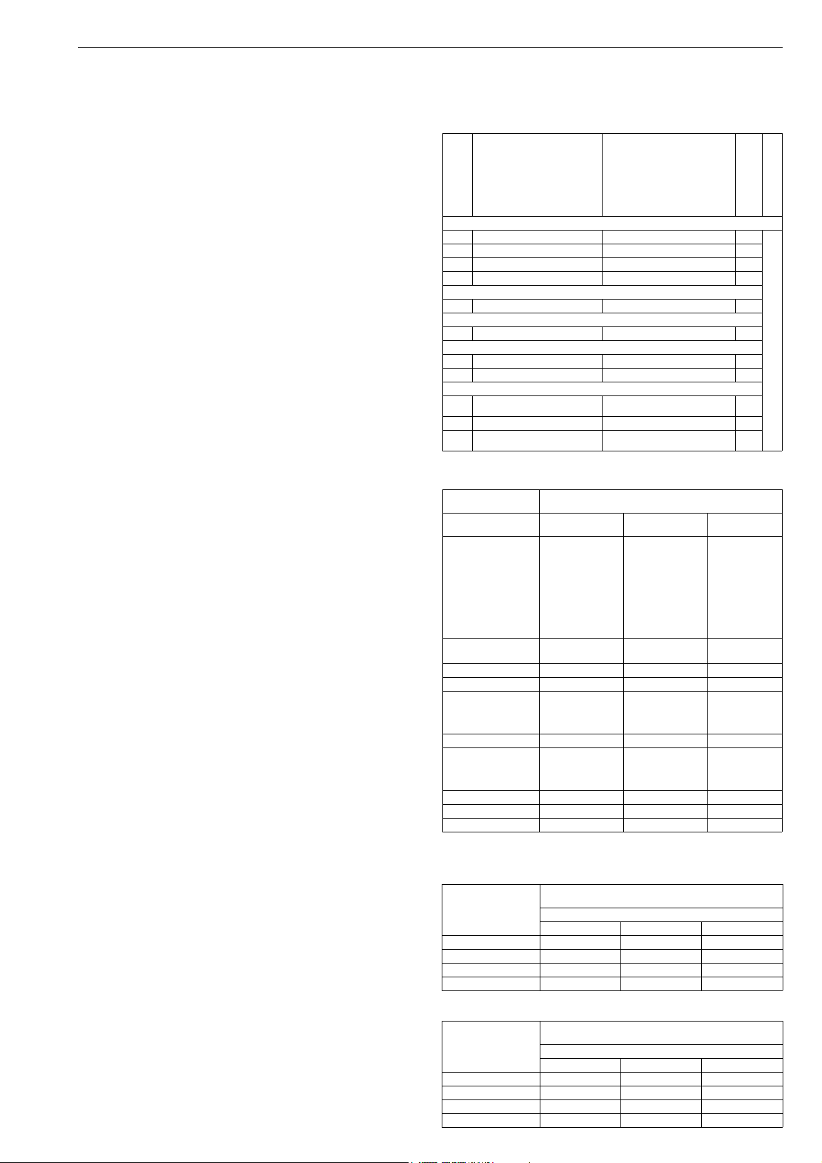
7 ND90 71 en 39
9.1.3.2 ND9000_/I__
Proximity switch type:Inductive
P+F NJ2-12GK-SN (I02)
P+F NCB2-12GM35-N0 (I09)
OMRON E2E-X2Y1 (I32)
P+F NJ4-12GK-SN (I41)
P+F NJ3-18GK-S1N (I45)
IFM IFC2002-ARKG/UP (I56)
Electrical values: According to switch type,
check connection diagram from
Section 12.11
Number of switches: 2
Protection class of housing:
IP66 (DIN 40050, IEC 60529)
Conduit entry: M20 x 1.5
(ND9100U and
ND9200E2, ND9300E2: 1/2 NPT)
SIL: Usable up to SIL3 acc. to
IEC61508 (02, 45)
Usable up to SIL2 acc. to IEC61508 (09)
9.1.4 Electric data and ambient
temperatures
Table 9
Switch type Electrical data
Limit switch code
2-wire, DC voltage proximity switches:
I02 P+F NJ2-12GK-SN Ui: 16 V, Ii: 52 mA 2
I09 P+F NCB2-12GM35-N0 Ui: 16 V, Ii: 52 mA 2
I56 IFM IFC2002-ARKG/UP U: 10-36 V DC, Imax: 150 mA 2
I41 P+F NJ4-12GK-SN Ui: 16 V, Ii: 52 mA 4
3-wire, DC voltage proximity switches:
I45 P+F NJ3-18GK-S1N Ui: 16 V DC, Ii: 52 mA 2
2-wire, AC voltage proximity switches:
I32 OMRON E2E-X2Y1 U: 24-240 V AC, Imax: 200 mA 2
Dual module type proximity switches::
D33 SST Dual Module, NO 2 A - 8-125 V DC, 24-125 V AC 1
D44 Namur Dual Module 3 mA; 1 mA, 6-29 V DC 1
DC/AC voltage micro switches:
K05 OMRON D2VW-5 3 A - 250 V AC, 0.4 A - 125 V DC,
K06 OMRON D2VW-01 100 mA - 30 V DC / 125 V AC 2
B06 OMRON D2VW-01 BUS POWERED, NO EXTERNAL
5 A - 30 V DC
POWER NEEDED
Max. Number
of switches
Ambient Range
2
2
See tables 9 ... 18
9.1.3.3 ND9000_/K0_
Microswitch type: OMRON D2VW-5 (K05)
OMRON D2VW-01 (K06)
(gold-plated contacts,
contact form is SPDT)
Protection class IP67
Resistive load: 3A: 250 V AC (K05)
5A: 30 V DC
0.4 A: 125 V DC
100 mA: 30 V DC/125 V AC (K06)
Switch accuracy: < 2°
Number of switches: 2
Protection class of housing:
IP66 (DIN 40050, IEC 60529)
Conduit entry: M20 x 1.5
(ND9100U and
ND9200E2, ND9300E2:
1/2 NPT)
9.1.3.4 ND9000F/B06, ND9000P/B06
Microswitch type: OMRON D2VW-01 (B06)
(gold-plated contacts,
contact form is SPDT)
Protection class IP67
Resistive load: 100 mA: 30 V DC/125 V AC
Switch accuracy: < 2°
Number of switches: 2
Protection class of housing:
IP66 (DIN 40050, IEC 60529)
Conduit entry: M20 x 1.5
(ND9100U and
ND9200E2, ND9300E2: 1/2 NPT)
Table 10
Ambient temperature ranges (Ta)
ND9000 T6
NDabcdE1e
NDabcdE1e/I02
NDabcdE1e/I04
NDabcdE1e/K05
NDabcdE1e/K06
NDabcdE1e/B06
NDabcdE1e/I32
NDabcdE1e/R35
NdabcdE1e/I41
NDabcdE1e/D33
NDabcdE1e/D44
NDabcdE1e/R01 -40° to +60 °C -40° to +75 °C -25° to +80 °C
NDabcdE1e/I59 -40° to +60 °C -40° to +60 °C -40° to +60 °C
NDabcdE1e/I09
NDabcdE1e/I45
NDabcdE1e/I57
NDabcdE1e/I58
NDabcdE1e/I56 -25° to +60 °C -25° to +75 °C -25° to +80 °C
NDabcdE1e/I11
NDabcdE1e/I21
NDabcdE1e/I34
NDabcdE1e/I60
NDabcdE1Ce** -53° to +60 °C -53° to +75 °C -53° to +85 °C
NDabcdE1Ce/I59** -53° to +60 °C -53° to +60 °C -53° to +60 °C
NDabcdE1Ce/I41** -50° to +60 °C -50° to +75 °C -50° to +85 °C
Not allowed with external junction box (J, -40 °C)
filled according to type
T80 °C
-40 ... +60 °C -40 ...+75 °C -40 ... +85 °C
-40... +60 °C -40° to +75 °C -40° to +82 °C
-25° to +60 °C -25° to +75 °C -25° to +85 °C
-25° to +60 °C -25° to +70 °C -25° to +70 °C
T5
T95 °C
T4
T105 °C
Table 11 Ambient temperatures, ND9_X
Variant type II 1 G Ex ia IIC T6...T4 Ga; II 1 D Ex ta IIIC T90 °C Da
ND91_X_ -40° to +50 °C -40° to +65 °C -40° to +80 °C
ND91_X/I02 -40° to +50 °C -40° to +64 °C -40° to +80 °C
ND91_X/I09 -25° to +50 °C -25° to +65 °C -25° to +80 °C
ND91_X/I45 -25° to +50 °C -25° to +64 °C -25° to +80 °C
II 2 G Ex ib IIC T6...T4 Gb; II 2 D Ex tb IIIC T90 °C Db
Ambient temperature ranges
T6 T5 T4
Table 12 Ambient temperatures, ND9_X
Variant type II 3 G Ex nA IIC T6...T4 Gc; II 3 D Ex tc IIIC T90 °C Dc
ND91_X -40° to +60 °C -40° to +75 °C -40° to +85 °C
ND91_X/I02 -40° to +60 °C -40° to +75 °C -40° to +85 °C
ND91_X/I09 -25° to +60 °C -25° to +75 °C -25° to +85 °C
ND91_X/I45 -25° to +60 °C -25° to +75 °C -25° to +85 °C
II 3 G Ex ic IIC T6...T4 Gc; II 3 D Ex tc IIIC T90 °C Dc
Ambient temperature ranges
T6 T5 T4

40 7 ND90 71 en
Table 13 Ambient temperatures, ND9_N
Variant type Ambien temperature ranges
ND_N_
ND_N_/I02
ND_N_/K05
ND_N_/K06
ND_N_/B06
ND_N_/I32
ND_N_/D33
ND_N_/D44
ND_N_/I45 -25° to +85 °C
ND_N_/I56 -25° to +80 °C
ND_NC_ (* -53° to +85 °C
ND_NC_/I41 (* -50° to +85 °C
Note *) Not allowed with external junction box (J, -40 °C)
-40° to +85 °C
-40° to +82 °C
Table 14 Ambient temperatures, ND9_U
Vari ant t ype IS Class I, Division 1, Groups A, B, C, D, T4...T6
ND9_U_ -40° to +50 °C -40° to +65 °C -40° to +80 °C
ND9_U/D44
ND9_U/I02
ND9_U/I09
ND9_U/I45
IS Class I, Zone 0, AEx ia, IIC T4...T6
Ambient temperature ranges
T6 T5 T4
Pendi ng
Table 15 Ambient temperatures, ND9_U
Vari ant t ype NI Class I, Division 2, Groups A, B, C, D, T4...T6
ND9_U_ -40° to +50 °C -40° to +65 °C -40° to +80 °C
ND9_U/D44
ND9_U/I02
ND9_U/I09
ND9_U/I45
NI Class I, Zone 2, Ex nA IIC T4...T6
Ambient temperature ranges
T6 T5 T4
Pendi ng
Table 16 Ambient temperatures, ND9_E2 (ND9_E4, only T6)
Vari ant t ype Ex d IIC T4…T6, AEx d IIC T4…T6
ND9_E2 -40° to +60 °C -40° to +75 °C -40° to +85 °C
ND9_E2/I02 -40° to +60 °C -40° to +75 °C -40° to +85 °C
ND9_E2/I09 -25° to +60 °C -25° to +75 °C -25° to +85 °C
ND9_E2/I32 -25° to +60 °C -25° to +70 °C -25° to +70 °C
ND9_E2/D33 -40° to +60 °C -40° to +75 °C -40° to +82 °C
ND9_E2/D44 -40° to +60 °C -40° to +75 °C -40° to +82 °C
ND9_E2/I45 -25° to +60 °C -25° to +75 °C -25° to +85 °C
ND9_E2/K05 -40° to +60 °C -40° to +75 °C -40° to +85 °C
ND9_E2/IK06 -40° to +60 °C -40° to +75 °C -40° to +85 °C
ND9_E2/B06 -40° to +60 °C -40° to +75 °C -40° to +85 °C
Ex tb IIIC T100 °C IP66, AEx tb IIIC T100 °C IP66
Ambient temperature ranges
T6 T5 T4
Table 17 Ambient temperatures, ND9_Z Inmetro
Vari ant t ype Ex ia IIC T4/T5/T6 Ga
ND91_Z -40° to +50 °C -40° to +65 °C -40° to +80 °C
ND91_Z/I02 -40° to +50 °C -40° to +64 °C -40° to +80 °C
ND91_Z/I09 -25° to +50 °C -25° to +65 °C -25° to +80 °C
ND91_Z/I45 -25° to +50 °C -25° to +64 °C -25° to +80 °C
Ex ia IIC T4/T5/T6 Gb
Ambient temperature ranges
T6 T5 T4
Table 18 Ambient temperatures, ND9_Z Inmetro
Vari ant t ype Ex nA IIC T4/T5/T6 Gc
ND91_Z_ -40° to +60 °C -40° to +75 °C -40° to +85 °C
ND91_Z/I02 -40° to +60 °C -40° to +75 °C -40° to +85 °C
ND91_Z/I09 -25° to +60 °C -25° to +75 °C -25° to +85 °C
ND91_Z/I45 -25° to +60 °C -25° to +75 °C -25° to +85 °C
Ex ic IIC T4/T5/T6 Gc
Ambient temperature ranges
T6 T5 T4
Table 19 Ambient temperatures, ND9_Z Inmetro
Vari ant t ype Ex d IIC T4/T5/T6 Gb
ND9_E1_
ND9_E1/I02
ND9_E1/K05
ND9_E1/K06
ND9_E1/B06
ND9_E1/D33
ND9_E1/D44
ND9_E1/I09
ND9...E1/I45
ND9_E1/I56 -25° to +60 °C -25° to +75 °C -25° to +80 °C
ND9_E1/I32 -25° to +60 °C -25° to +70 °C -25° to +70 °C
Ex tb IIIC T100 °C Db IP66
Ambient temperature ranges
T6 T5 T4
-40° to +60 °C -40° to +75 °C -40° to +85 °C
-40° to +60 °C -40° to +75 °C -40° to +82 °C
-25° to +60 °C -25° to +75 °C -25° to +85 °C
9.2 Installation on a valve controller
The limit switch may be installed on an existing valve controller.
ND9100
If the valve controller is already mounted on an actu-
ator/valve assembly, operate the actuator into the
closed or open position.
Remove the cover (100), the pointer (109), the LUI
(223), the prestage cover (43) and electronics cover
(39).
Turn the shaft (311) onto the shaft (11). Fasten the
screw (312) using a locking agent such as Loctite.
Unfasten the screws (314) in the cam discs (313).
Mount the electronics cover (39) and the housing
(300) on the valve controller.
ND9100/K00: Turn the cam discs (313) to avoid con-
tact with the micro switches, if required.
Mount the LUI (223) on the bed (306).
Mount the pointer (109) on the shaft (311). Adjust
the limit switch according to 9.4.
ND9200, ND9300
If the valve controller is already mounted on an actu-
ator/valve assembly, operate the actuator into the
closed or open position.
Remove the cover (100), the pointer (109), the LUI
(223) and electronics cover (39).
Turn the shaft (311) onto the shaft (11). Fasten the
screw (312) using a locking agent such as Loctite.
Mount the electronics cover (39) and the limit switch
housing (300) on the valve controller. Lock the housing in place with screw (326). Install the base plate
(324) with the limit switches and connector block
into the limit switch housing. Fasten the base plate
with screws (325), 3 pcs.
Install the cam discs (313) and bushings (346) to the
shaft.
Mount the LUI (223) on the holder (306).
Replace the plastic plugs with metal ones in conduit
entries which will not be used.
Mount the pointer (109) on the shaft (311). Adjust
the limit switch according to 9.4.
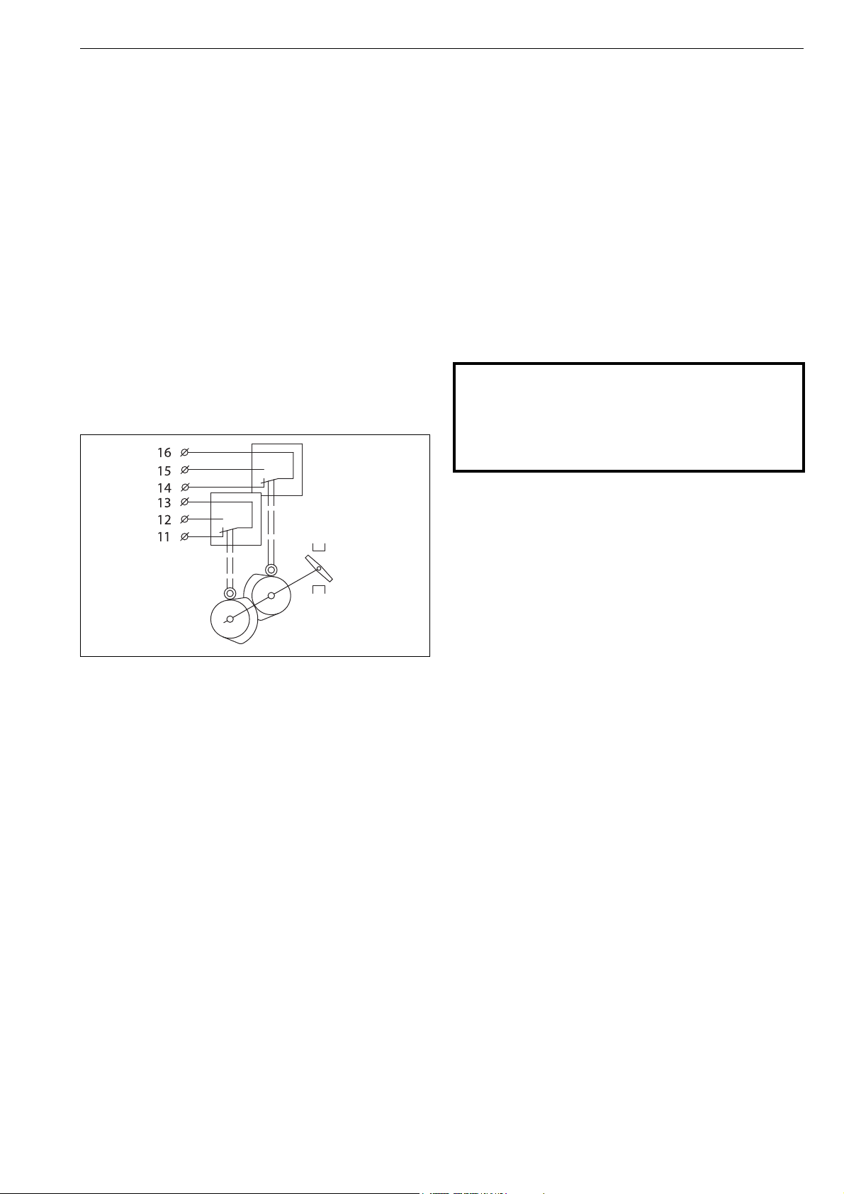
7 ND90 71 en 41
Open
Close
9.3 Electrical connections
Before connecting the power, make sure that the electrical
specifications and the wiring meet the installation conditions. See the diagrams in 12.11. Refer to the information on
the identification plate.
ND9000/D__ and ND9000/I__: Observe the functioning of
the proximity switch; activated when the active face is
either covered or free.
9.4 Adjustment
The pointer (109) need not be removed for adjustment.
When the limit switch is ordered together with the valve
and the actuator, the valve controller switches are factoryadjusted. The limits may be adjusted by altering the position of the cam discs (313) on the shaft.
The lower switch is activated at the closed limit and the
upper switch at the open limit.
With the actuator in the open or closed position,
locate the switching point by turning the cam disc so
that the switch state changes approx. 5°–6° before
the limit.
ND9200, ND9300
Remove the cover (100) and the pointer (109).
Loosen the screws (314) in the cam disks (313) and
remove the cam disks and spacers (346) from the
shaft.
Remove the LUI cabling from the circuit board. Dis-
connect and remove all cabling which enters the
limit switch housing (300).
Remove screws (325), 3 pcs. and lift out the limit
switch base plate (324) complete with switches, LUI
and connector block.
Open screw (326) and turn the limit switch housing
(300) from the positioner housing.
Remove the electronics cover (39).
Proceed with the valve controller as applicable.
Re-install the limit switch according to 9.2 and check
the adjustment according to 9.4.
Ex WARNING:
The locking screw of the limit switch housing (Part
326) is essential to explosion protection.
The limit switch housing has to be locked in place for Ex d
protection. The screw grounds the limit switch housing to
the housing of the valve controller.
Fig. 48 Limit switch adjustment, 2 switches
ND9000/D__ and ND9000/I__: Use the LED indica-
tor or a separate measuring instrument as an aid.
After re-installation of the actuator, first adjust its
mechanical limits according to the valve, then the
valve controller, and finally the limit switch.
When adjustment is completed, turn the pointer
(109) so that the yellow line is parallel with the valve
closure member.
9.5 Removal of the limit switches for
accessing the valve controller
ND9100
Remove the cover (100) and the pointer (109).
Detach the cam discs (313).
Remove the LUI cabling from the circuit board.
Loosen the screws (303) and remove the housing
(300).
Remove the electronics cover (39).
Proceed with the valve controller as applicable.
Re-install the limit switch according to 9.2 and check
the adjustment according to 9.4.
9.6 Circuit diagrams
The internal circuitry of the limit switch is shown in the connection diagrams in 12.11 and inside the cover (not
ND9100H/I__).
9.7 Maintenance
Regular maintenance of the limit switch is not necessary.
10 TOOLS
Following tools are needed for the product installation and
service:
Flat screwdriver
0.4 x 2.5 x 80 mm
1.2 x 6.5 x 150 mm
Tor x screw driver
T10
T15
T20
Phillips screwdriver
PH1 x 60 mm
Allen key
2 mm
4 mm
5 mm
Other tools are depended on actuator where ND installed.
11 ORDERING SPARE PARTS
Spare parts are delivered as modules. The modules available are indicated in 12.1 and 12.3.
When ordering spare parts, always include the following
information:
Valve controller type designation and serial number
from the ID plate
The code of this manual, the part number, the part
name and quantity required

42 7 ND90 71 en
100
39
1
8
1
10
109
228
215
220
218
210
11
221
15
16
12*
14*
44
43
120
219
139
9
107
48
47
223
42
217
49
193
19
18
222
36
436437 439
12 DRAWINGS AND PARTS LISTS
12.1 Exploded view ND9100, ND9400, ND7100
Item Qty Description Spare part modules
11Housing
81Exhaust cover
92Screw
11 1 Shaft
15 1 O-ring
16 1 Washer
18 1 Wave spring
19 1 Bushing
36 1 Grounding screw
39 1 Electronics cover
42 4 Screw
43 1 Prestage cover
44 1 Screw
47 3 Screw
48 2 Screw
49 1 Screw
100 1 Cover ND91_ = H035118, ND71_ = H099717, includes item 107
107 4 Screw
109 1 Pointer
110 1 Grub screw
120 1 Prestage unit H039292, includes item 139
139 2 Screw
x
193
210 1 Valve Controller board
215
217 4 Screw
1 Spool valve assembly ND9102 = H060178, ND9103 = H039293, ND9106 = H039294,
** 1 Communication board ND9_H = H039296, ND9_HT = H041368, ND9_F = H033594, ND9_P = H033595
218 1 Support
219 2 Screw
kits include items 47, 48, 49
220 2 Threaded spacer
221 3 O-ring
222 1 Isolation part
223 1 Local user interface (LUI) H039295, includes item 228
228 2 Screw
436 1 Connection box Not available with ND7000
437 1 Nipple
439 2 Nut
*) Mounting parts: coupling (12), screws (14)
**) PH number from the ID plate is required
x) Spool valve assembly includes the spool valve with the fastener. Separate ID code for fastener is H077294. This contains also all gaskets and diaphragms.
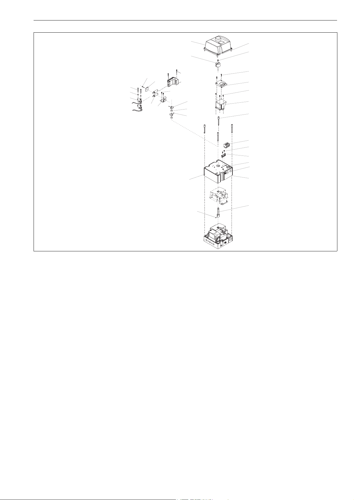
7 ND90 71 en 43
358
357
355
100
110
109
107
313
302
301
300
311
315
303
306
307
308
346
349
348
347
314
350
351
305
304
312
223
36
I__
K0_
B06
D__
322
323
12.2 Exploded view ND9100_/D__, ND9100_/I__, ND9100_/K0_ and ND9100_/B06
Item Qty Description
36 1 Grounding screw
100 1 Cover
107 4 Screw
109 1 Pointer
110 1 Screw
223 1 Local user interface (LUI)
300 1 Housing
301 1 Gasket
302 1 Screw
303 4 Screw
304 1 Bracket
305 2 Screw
306 1 Bed of Local User Interface (LUI)
307 3 Screw
308 2 Screw
311 1 Shaft
312 2 Screw
313 2 Cam disc
314 2 Screw
315 6 Terminal block
322 1 Proximity switch (D__)
323 2 Screw
346 1 or 2 Bushing (I__)
347 2 Inductive proximity sensor (I__)
348 1 Fastening plate
349 2 Screw
350 1 Washer
351 1 Screw
355 2 Microswitch (K0_, B06)
357 2 Spring washer (K0_, B06)
358 2 Screw (K0_, B06)

44 7 ND90 71 en
107
110
109
228
223
39
215
220
210
19
18
104
182
221
2
197
196
181
200
177
176
170
184
169**
171
173
14*
174
193
63
61
47
15
16
12*
100
42
222
173
167
165
166
120
139
164
162**
163
217
218
219
199
183
140
36
111
ND9300
ND9300, ND9200_E2
ND9200
ND7200
57
437 439 436
450
448
451
449
458
57
436437 439
12.3 Exploded view ND9200, ND9300, ND7200

7 ND90 71 en 45
Item Qty Description Spare part modules
21Housing
15 1 O-ring
16 1 Washer
18 1 Wave spring
19 1 Bushing
36 1 Grounding screw
39 1 Inner cover
42 3 Screw
47 3 Screw
57 1 Conduit entry adapter
61 1 Spool valve cover
63 1 Gasket
100 1 Cover ND92_E1 = H087634, ND92_E2 = H087617, ND9300 = H087628
104 1 O-ring
107 1 Screw
109 1 Pointer
110 1 Stop screw
111 1 Spring
120 1 Prestage unit H039292, also includes items 139 and 140
139 2 Screw
140 1 O-ring
162
** 1 Supply pressure diaphragm ND92 = H048584, ND93 = H078592, ND72 = H048584
163 1 Diaphragm plate
164
** 1 Spring guide
165
** 1O-ring
166 1 Spring
167 1 Diaphgram cover
169
** 1Pilot pressure diaphgram
170 1 Diaphragm plate
171 1 Diaphragm cover
173 8 Screw
174 1 Gasket
176 1 Bushing
177
** 1O-ring
181 1 Sleeve
182 1 Spool sensor board
183 1 Screw
184 1 Plunger
193 1 Spo ol val ve ND9202 = H060179, ND9203 = H048586, ND9206 = H048587, ND9302 = H076999,
196 1 Bushing
197 1 Restriction assembly
199 1 O-ring
200 1 Flame arrester H080913
210 1 Valve controller board
215
*** 1 Communication board ND9_H = H039296, ND9_HT = H041368, ND9_F = H033594, ND9_P = H033595
217 4 Screw
218 1 Support
219 2 Screw
220 2 Threaded spacer
221 3 O-ring
222 1 Isolation part
223 1 Local user interface (LUI) H039295, includes item 228
228 2 Screw
436 1 Connection box Not available with ND7000
437 1 Nipple
439 2 Nut
448 1 Bracket
449 2 Screw
450 1 Screw
451 1 Hexagon nut
458 1 Washer
ND72_E1 = H087634, ND72_E2 = H087617
ND9303 = H077000, ND9306 = H077001
ND7202 = H060179, ND7203 = H048586, ND7206 = H048587, also includes item 63
*) Mounting parts: coupling (12), screws (14)
**) Diaphgram set includes additional ** marked parts
***) PH number from the ID plate is required

46 7 ND90 71 en
107
110
109
308
223
104
100
311
312
301
313
315
346
349
348
347
314
350
351
305
304
I__
324
300
307
306
325
326
302
358
357
355
K0_
B06
111
11
1
100
ND9200
ND9300
ND9300
D__
322
323
12.4 Exploded view ND9200_/D__, ND9200_/I__, ND9200_/K0_, ND9200_/B06,
ND9300_/D__, ND9300_/I__, ND9300_/K0_, ND9300_/B06_

7 ND90 71 en 47
Item Qty Description
100 1 Cover
104 1 O-ring
107 1 Screw
109 1 Pointer
110 1 Stop screw
111 2 Spring (ND9200)
223 1 Local user interface (LUI)
300 1 Housing
301 1 O-ring
302 1 Screw
304 1 Bracket
305 2 Screw
306 1 Bracket
307 3 Screw
308 2 Screw
311 1 Extension shaft
312 2 Screw
313 2 or 4 Cam disc
314 2 or 4 Screw
315 1 Terminal block
322 1 Proximity switch
323 2 Screw
324 1 Base plate
325 2 Screw
326 1 Screw
346 1 or 2 Bushing
347 2 Proximity switch
348 1 Fixing plate
349 2 Screw
350 1 Washer
351 1 Screw
355 2 or 4 Microswitch
357 2 Spring washer
358 2 Screw

48 7 ND90 71 en
Item Qty Description
1 1 Mounting bracket
21Ear
34Washer
44Screw
28 4 Screw
29 1 Screw
36 1 Couplings jacket
47 1 Coupler socket
48 2 Screw
53 1 Plug (BJ actuators only)
54 2 Plug
Item Qty Description
1 1 Mounting bracket
21Draught piece
34Washer
44Screw
13 2 Screw
14 2 Hexagon nut
28 4 Screw
29 1 Screw
47 1 Coupler socket
48 2 Screw
53 1 Plug (BJ actuators only)
54 2 Plug
ND9100
VDI/VDE 3845
ND9100
Neles
attachment faceattachment face
ND7100
ND7100
Item Qty Description
1 1 Mounting bracket
21Ear
34Washer
44Screw
28 4 Screw
29 1 Screw
36 1 Couplings jacket
47 1 Coupler socket
48 2 Screw
53 1 Plug (BJ actuators only)
Item Qty Description
1 1 Mounting bracket
21Draught piece
34Washer
44Screw
13 2 Screw
14 2 Hexagon nut
28 4 Screw
29 1 Screw
47 1 Coupler socket
48 2 Screw
53 1 Plug (BJ actuators only)
Note: See 12.7 for old series B actuators
ND9200
VDI/VDE 3845
ND9200
Neles
attachment face attachment face
Note:
Different mounting
position
ND9300 ND9300
ND7200 ND7200
12.5 Mounting parts for B1C/B1J 6-20 actuators
ND9100, ND7100
ND9200, ND9300, ND7200

7 ND90 71 en 49
Item Qty Description
1 1 Mounting bracket
21Draught piece
34Washer
44Screw
27 4 Washer
28 4 Screw
47 1 Coupler socket
48 2 Screw
53 1 Plug (BJ actuators only)
54 2 Plug
ND9100
ND7100
Item Qty Description
1 1 Mounting bracket
21Draught piece
34Washer
44Screw
27 4 Washer
28 4 Screw
47 1 Coupler socket
48 2 Screw
53 1 Plug (BJ actuators only)
ND9200
90°
45°
21
Arrow
new hole drilled
ø5.5 through
Note: Old series B actuators
Note:
Different mounting
position
ND9300
ND7200
12.6 Mounting parts for B1C/B1J 25-50, B1C 502 and B1J322 actuators
ND9100, ND7100
ND9200, ND9300, ND7200
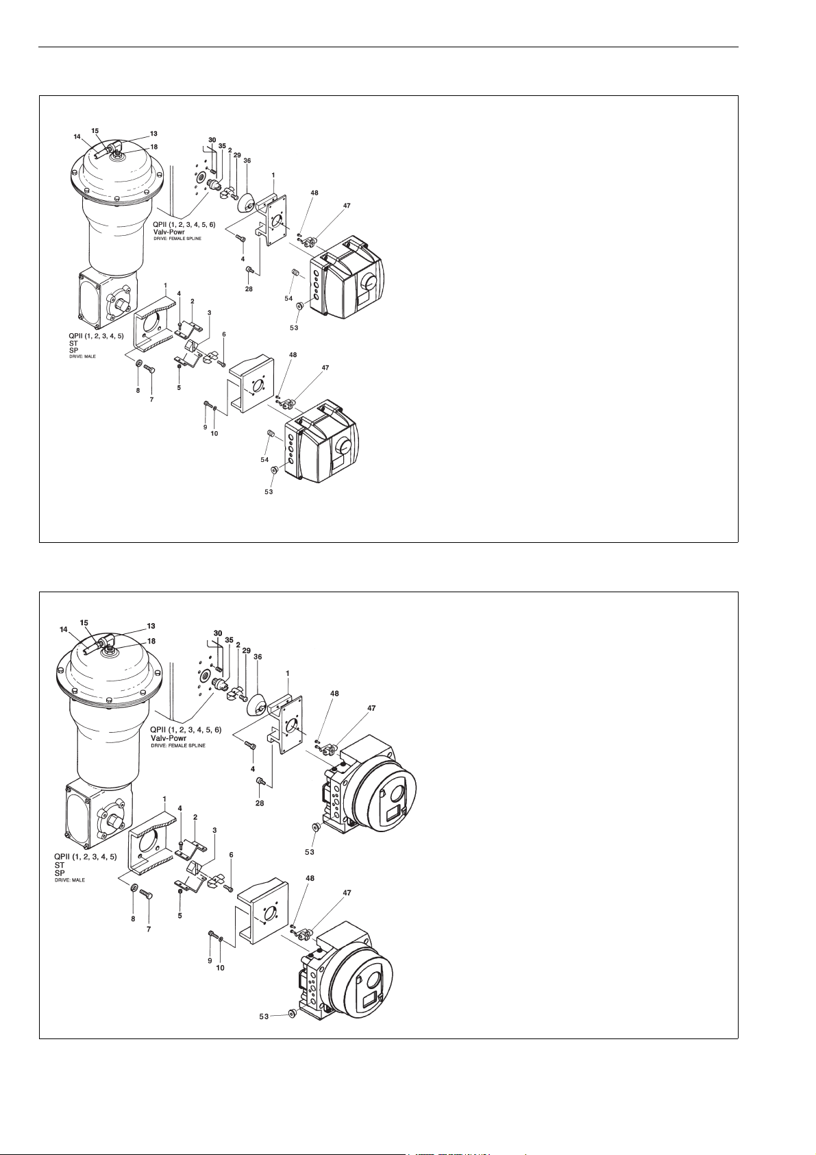
50 7 ND90 71 en
Item Qty Description
1 1 Mounting bracket
21Ear
44Screw
28 4 Screw
29 1 Screw
30 4 Screw
35 1 Adapter plug
(QP II 1/S- 6/S only)
35 1 Adapter plate
(QP II 2B/K thr. 6_/K)
36 1 Couplings jacket
47 1 Coupler socket
48 2 Screw
53 1 Plug
54 2 Plug
Item Qty Description
1 1 Mounting bracket
2 2 Coupling half
31Adapter
44Screw
54Hex nut
61Screw
74Screw
84Washer
94Screw
10 4 Washer
47 1 Coupler socket
48 2 Screw
53 1 Plug
54 2 Plug
ND9100
ND9100
ND7100
ND7100
Item Qty Description
1 1 Mounting bracket
21Ear
44Screw
28 4 Screw
29 1 Screw
30 4 Screw
35 1 Adapter plug
(QP II 1/S- 6/S only)
35 1 Adapter plate
(QP II 2B/K thr. 6_/K)
36 1 Couplings jacket
47 1 Coupler socket
48 2 Screw
53 1 Plug
Item Qty Description
1 1 Mounting bracket
2 2 Coupling half
31Adapter
44Screw
54Hex nut
61Screw
74Screw
84Washer
94Screw
10 4 Washer
47 1 Coupler socket
48 2 Screw
53 1 Plug
ND9200
ND9200
ND9300
ND9300
ND7200
ND7200
12.7 Mounting parts for Quadra-Powr® actuators
ND9100, ND7100
ND9200, ND9300, ND7200

7 ND90 71 en 51
1
11
9
1412 11
3
65
19 18 15
8
7
2
4
Scale on this side
Stroke 10 - 120 mm
1617
Feedback lever in horizontal position
at mid travel of stroke.
Plane in the shaft in this position
with feedback lever
54
Allowed travel range 45–90°
45-90°
(10 - 120 mm)
Stroke
Item Qty Description
1 1 Bracket
2 1 Feedback lever
3 1 Filling piece
4 1 Clearance remove spring
5 4 Cross rec head screw
64Washer
74Hexagon screw
84Washer
94Hexagon screw
11 4 Spring washer
12 2 Hexagon nut
14 2 Clamp
15 1 Fixing plate
16 1 Special screw
17 1 Hexagon nut
18 2 Washer
19 2 Hexagon screw
54 2 Plug
12.8 Mounting on Neles VC and VD actuators or linear actuators with IEC 60534 mounting face.
ND9100, ND7100
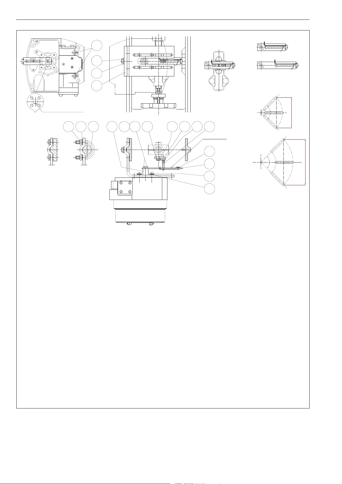
52 7 ND90 71 en
1
11
9
1412 11
3
65
19 18 15
8
7
2
4
Scale on this side
Stroke 60 - 120) mm
Stroke 10 - 80 mm
1617
Feedback lever in horizontal position
at mid travel of stroke.
Plane in the shaft in this position
with feedback lever
54
Maximum stroke 120 mm
Maximum stroke 80 mm
Allowed travel range 45–90°
45°
45°
45°
45°
Item Qty Description
11Bracket
21Feedback lever
31Filling piece
4 1 Clearance remove spring
5 4 Cross rec head screw
64Washer
74Hexagon screw
84Washer
94Hexagon screw
11 4 Spring washer
12 2 Hexagon nut
14 2 Clamp
15 1 Fixing plate
16 1 Special screw
17 1 Hexagon nut
18 2 Washer
19 2 Hexagon screw
54 2 Plug
ND9200, ND9300, ND7200

7 ND90 71 en 53
ND9000/D33
Connections SOL1, SOL2, SOL PWR1 and SOL PWR2 are not used.
TOP SW NO: Positive connection for top switch
TOP SW C: Negative connection for top switch
BTM SW NO: Positive connection for bottom switch
BTM SW C: Negative connection for bottom switch
See Section 9.1.3.1 for electrical ratings.
ND9000/D44
Connections SOL1, SOL2, SOL PWR1 and SOLP WR2 are not used.
TOP SW +: Positive connection for top switch
TOP SW -: Negative connection for top switch
BTM SW +: Positive connection for bottom switch
BTM SW -: Negative connection for bottom switch
See Section 9.1.3.1 for electrical ratings.
TOP SW +
TOP SW -
BTM SW -
BTM SW +
SOL PWR 2
SOL PWR 1
SOL 1
SOL 2
12.9 Connection diagrams
See Section 9.1.3 for additional limit switch data.
SOL 1
SOL 2
SOL PWR 1
SOL PWR 2
TOP SW NO
TOP SW C
BTM SW NO
BTM SW C

54 7 ND90 71 en
ND9000/I02, I09
11
blue
brown
K
A
blue
brown
OPEN
CLOSED
13
14
16
Factory adjustment
Active faces of proximity switches are covered when actuator is in intermediate position.
Active face A (upper switch) becomes free at open limit of travel and face K (lower switch) at closed limit.
Function can be inverted on site by re-adjusting the cam discs.
ND9000/I32
K
A
OPEN
CLOSED
13
14
16
AC
AC
brown
blue
brown
blue
11
Factory adjustment
Active faces of proximity switches are free when actuator is in intermediate position.
Active face A (upper switch) becomes covered at open limit of travel and face K (lower switch) at closed limit.
Function can be inverted on site by re-adjusting the cam discs.
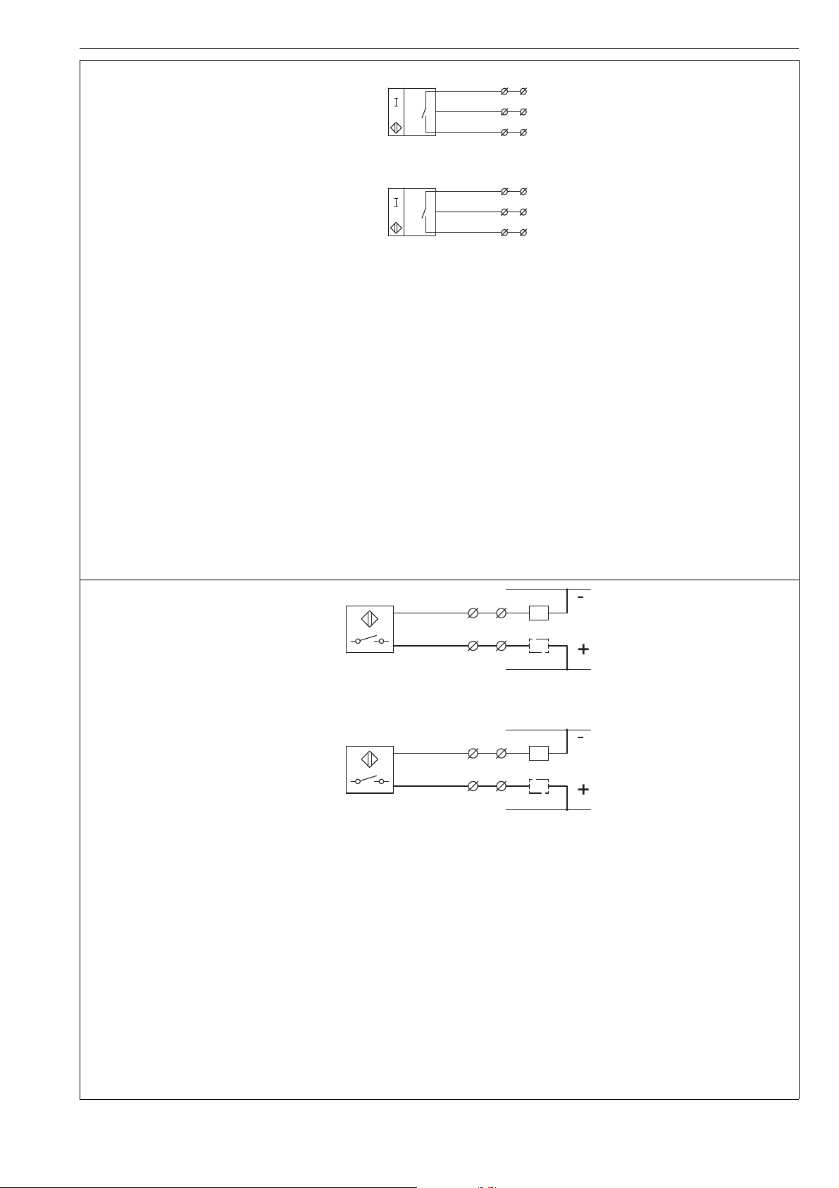
7 ND90 71 en 55
ND9000/I45
K
A
L-
S1N
S1N
L+
L-
L+
OPEN
CLOSED
black
blue
brown
11
12
13
14
15
16
black
blue
brown
Factory adjustment
Active faces of proximity switches are covered when actuator is in intermediate position.
Active face A (upper switch) becomes free at open limit of travel and face K (lower switch) at closed limit.
Function can be inverted on site by re-adjusting the cam discs.
ND9000/I56
Factory adjustment
Active faces of proximity switches are free when actuator is in intermediate position.
Active face A (upper switch) becomes covered at open limit of travel and face K (lower switch) at closed limit.
Function can be inverted on site by re-adjusting the cam discs.
Connections: Load can be connected to + or -.
CLOSED
black
AOPEN
K
black
black
black
11
13
14
16
DC
DC

56 7 ND90 71 en
ND9000/K_
Connection diagram shows limit switch when actuator is in intermediate position.
Switch A (upper) is activated at the open limit of the travel and switch K (lower) at the closed limit.
ND9000F/B06, ND9000P/B06
Bus powered switches, no external connections.
Microswitch
OMRON D2VW-01
Gold plated contacts
Bus Powered, no external power needed.
Temperature range: -40° to +85 °C / -40° to +185 °F.
LS1
LS2
12
13
15
16
1: LS1 (open)
2: LS2 (closed)
3: GND
11
red
12
OPEN
CLOSED
A
K
blue
black
red
blue
black
13
14
15
16

7 ND90 71 en 57
ND9000H
+
-
JB
G
3
+
-
mA
PT
5
6
4
G
ND9000H_J
ND9000F/P
JB
G
3
+
-
5
6
4
G
ND9000F_J, ND9000P_J
Surge protection
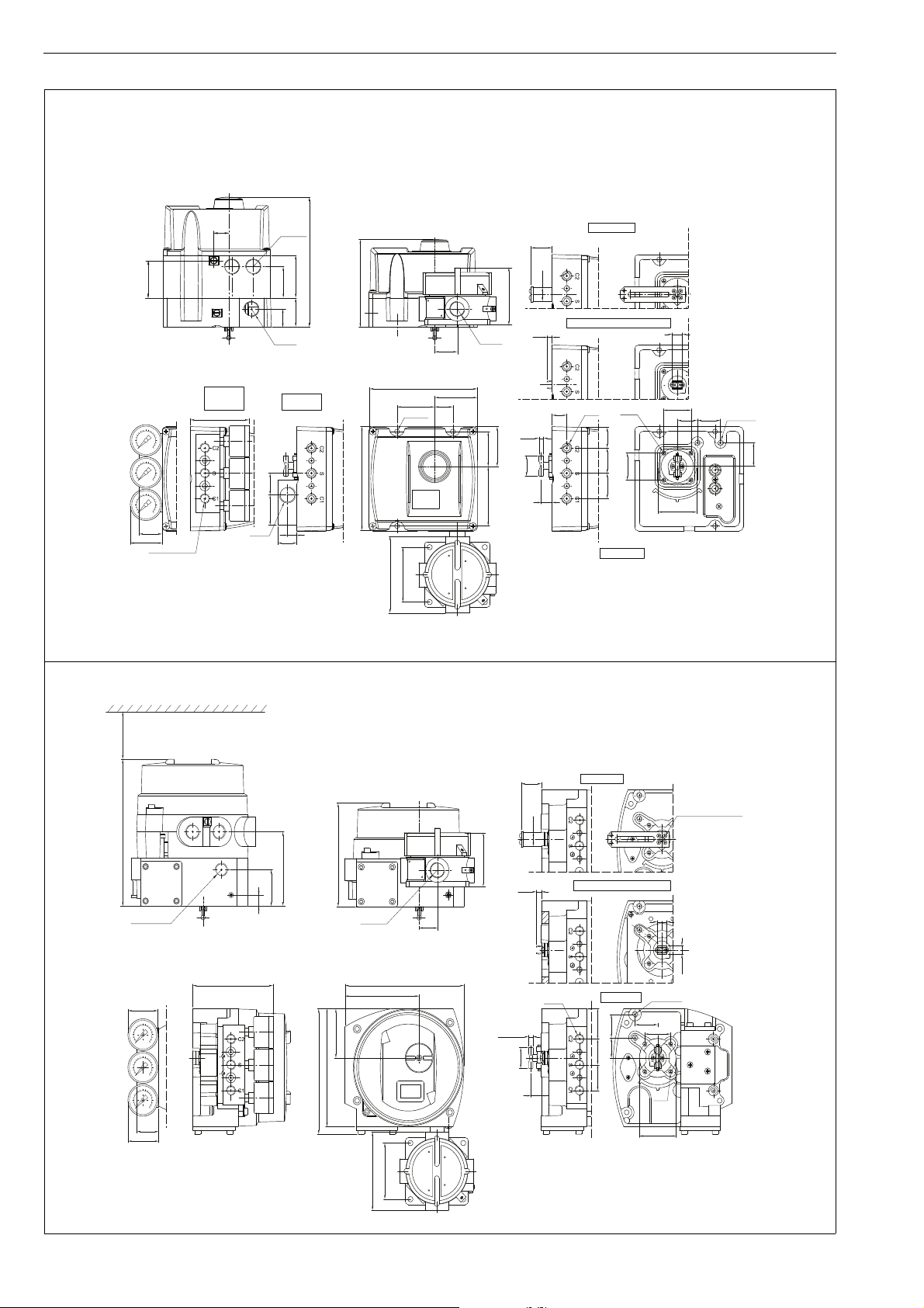
58 7 ND90 71 en
ND9100, ND9400, ND7100
114
M20x1.5
30
55
52
135
140
77
30
42
G1/4 or 1/4 NPT
49
23.5
45.577.5
M6/10
(35.4)
G1/4
26.8
ø6
14.5
26.8
33 33
19
(35.4)
F05-ø50
13
6
27.5
ø18
26 30
31
ø6 (3 pcs)
5/16 UNC/13
12
28.25
24.5
1/2 NPT
39.5
23.5
76
170
5638
41
M20 x 1.5
49.5
20
100
73
M20x1.5
Linear actuator
Flush mounting for EC/EJ actuators
VDI/VDE 3845
G (1/2 NPT)
A1 (G1/4)
A3 (1/4 NPT)
AR (Rc 1/4)
ND9100/D, ND9100/I, ND9100/K and ND9100/B
ND9100, ND9400, ND7100
Option J
ND9200, ND7200
30
42
110
ø18
28
6.5
13
14.5
26.8
ø6
393333
1/4 NPT
5/16UNC/13
31
26 30
F05-ø50
(35.4)
M6/10
S
25
47
133
162
41
161
63
101
10.5
The feedback lever
according to actuator
151
95
190
ND920_E2 and ND920_E4: M20x1,5/1/2 NPT
(1/2 NPT, G 1/2)
min. 60
15
100
73
M20x1.5
76
VDI/VDE 3845
Direct mounting for EC/EJ actuators
Linear actuator
ND9200/D, ND9200/I, ND9200/K and ND9200/B
ND9200, ND7200
Option J (pending)
Not available with ND7200
13 DIMENSIONS
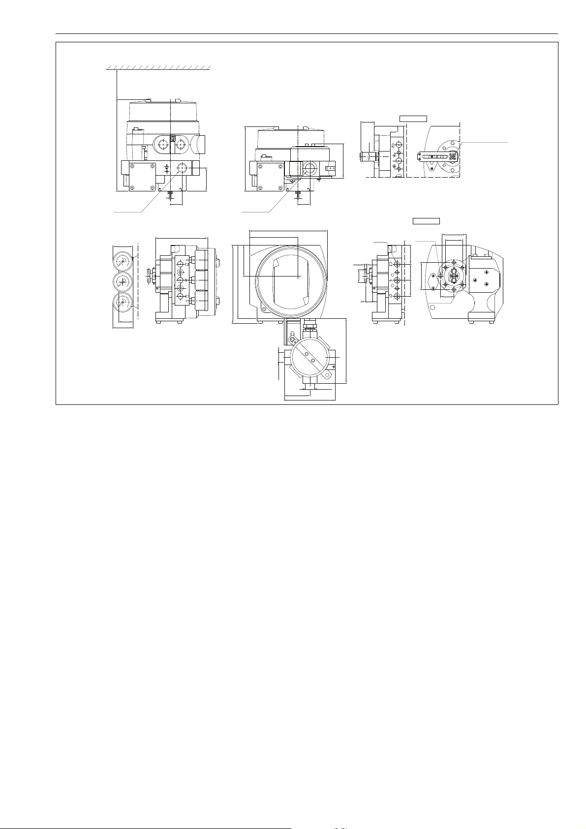
7 ND90 71 en 59
ND9300
30
42
ø18
28
S
25
M20x1.5
133
162
41
161
63
101
The feedback lever
according to actuator
151
(35.4)
F05-ø50
M6x10 (4 pcs.)
56
28
M8x15 (3 pcs.)
1/4 NPT
393333
14.5
26.8
ø6
110
133
71
VDI/VDE 3845
Linear actuator
25
47
ND930_E1, E5, E7: M20x1.5
ND930_E2: M20x1,5/1/2 NPT (CONDUIT ENTRY NIPPLE)
190
ND930_E4: 1/2 NPT, G1/2 (CONDUIT ENTRY NIPPLE AND CABLE ENTRY ADAPTER)
53
M20x1.5
M20x1.5
107
min. 60
ND9300/D, ND9300/I, ND9300/K and ND9300/B
ND9300
Option J

60 7 ND90 71 en
EC DECLARATION OF CONFORMITY
Manufacturer:
Metso Oy
01301 Vantaa
Finland
Product:
Intelligent Valve Controller Neles ND 9000- and ND 7000-series
Approvals:
Type Approval EC Type examination Certificate
ND9...PA(Profibus PA)
ND9...F (Foundation Fieldbus)
EMC 2014/30/EU
EN 61000-6-4 (2007) + A1(2011)
EN 61000-6-2 (2005)
SGS Fimko 278969-1
ND9…
ND7...HNT (Hart)
HNT (Hart) EMC 2014/30/EU
EN 61000-6-4 (2007) + A1(2011)
EN 61000-6-2 (2005)
SGS Fimko 276525-2
ND910.HX
ND910.FX
ND910.PX
ND920.HX
ND920.FX
ND920.PX
ND930.HX
ND930.FX
ND930.PX
ND710.HX
ND920...E1, ND930...E1
ND720...E1
ND920...E7, ND930...E7
ND720...E7
As the products within our sole responsibility of design and manufacture may be used as parts or components in machinery and are not alone
performing functions as described in Article 6(2) in the Machinery Directive (2006/42/EC), we declare that our product(s) to which this Declaration of
Conformity relates must NOT be put into service until the relevant machinery into which it is to be incorporated has been declared in conformity with
the provisions of the Machinery Directive.
The product above is manufactured in compliance with the applicable European directives and technical specifications/standards.
Protection from e.g. static electricity caused by the process or connected equipment must be considered by the user (EN 60079-14§6).
The product do not possess any residual risk according to hazard analyses made under the applicable directives providing that the procedures
stated by the Installation, Operation and Maintenance manual are followed and the product is used under conditions mentioned in the technical
specifications.
Vantaa 16th January 2019
Juha Virolainen, Quality Manager
Authorized person of the manufacturer within the European Community
VTT 09ATEX 033X
EN 60079-0: 2012,
EN 60079-11: 2012,
EN 60079-26: 2007,
EN 60079-31:2009
VTT 09ATEX 034X
EN 60079-0: 2012,
EN 60079-11: 2012,
EN 60079-15: 2010,
EN 60079-31:2009
SIRA 11 ATEX 1006X
EN 60079-0:2012, EN 60079-1:2007
EN 60079-31:2009
Applicable directives:
EMC 2014/30/EU Electrical
ATEX 94/9/EC (until 19 April 2016) Approved and Ex marked types
ATEX 2014/34/EU (from 20 April 2016)
ATEX Notified Bodies for EC Type Examination Certificate:
SIRA (Notified body number 0518)
SIRA Certification Service
CSA Group
Unit 6, Hawarden lndustrial Park
Hawarden, Deeside, CHs 3US
United Kingdom
VTT (Notified body number 0537)
VTT, Expert Services
Otakaari 7B, Espoo
P.O.Box 1000, FI-02044 VTT
Finland
ATEX Notified Body for Quality Assurance:
ISO 9001:2008 Certificate No: 73538-2010-AQ-FIN-FINAS
ATEX 94/9/EC Annex IV Certificate No: DNV-2006-OSL-ATEX-0260Q
Det Norske Veritas AS (Notified body number 2460)
Veritasveien 1
1322 Høvik, Oslo
Norway
ATEX II 1 G Ex ia IIC T6...T4 Ga
ATEX II 1 D Ex ta IIIC T90 °C Da
ATEX II 1 D Ex ia IIIC T90...T120 °C Da
ATEX II 2 G Ex ib IIC T6...T4 Gb
ATEX II 2 D Ex tb IIIC T90 °C Db
ATEX II 2 D Ex ib IIIC T90...T120 °C Db
ATEX II 3 G Ex nA IIC T6...T4 Gc
ATEX II 3 D Ex tc IIIC T90 °C Dc
ATEX II 3 D Ex ic IIIC T90 °C...T120 °C Dc
ATEX II 3 G Ex ic IIC T6...T4 Gb
ATEX II 3 D Ex tc IIIC T90 °C Dc
ATEX II 3 D Ex ic IIIC T90 °C...T120 °C Dc
ATEX II 2 G Ex d IIC T6...T4 Gb
ATEX II 2 D Ex tb IIIC T80 °C...T105 °C Db IP66
14 EC DECLARATION OF CONFORMITY

7 ND90 71 en 61
METSO AUTOMATION OY
VANHA PORVOONTIE 229, 01380 VANTAA, FINLAND
TYPE ND9203HE2 REV 2.4
CLASS I, DIV 1, GPS B, C, D; CLASS II, DIV 1, GPS E, F, G;
CLASS III; T4...T6, ENCLOSURE TYPE 4X;
Ex d IIC T4 T6, AEx d IIC T4...T6;
Ex tb IIIC T100 °C IP66, AEx tb IIIC T100 °C IP66
CSA 08.1980091
Tamb. T6: -40...+60 °C, T5: -40...+75 °C, T4: -40...+85 °C
4-20 mA INPUT: (9.5 V DC/20 mA/475 Ohm) Ui: 30 V DC
SUPPLY PRESSURE: 1.4-8 bar / 20-115 psi
SEAL AT CONDUIT ENTRY
WARNING: DO NOT OPEN WHEN ENERGIZED
ID: C00012345^INO: PH12240004
15 ID PLATES
ATEX / IECEx: II 1 G Ex ia, II 1 D Ex ta
II 2 G Ex ib, II 2 D Ex tb
II 3 G Ex nA, II 3 D Ex tc
II 3 G Ex ic, II 3 D Ex tc
ATEX / IECEx: II 2 G Ex d , II 2D Ex tb IIIC
cCSAus: Explosion proof
cCSAus: Intrinsically safe
cCSAus: Non incendive
Japanese Ex-d Certification:
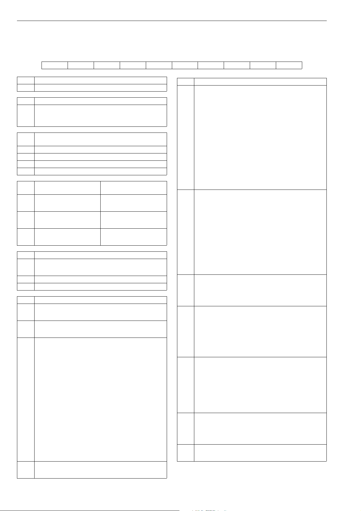
62 7 ND90 71 en
16 TYPE CODING
INTELLIGENT VALVE CONTROLLER ND9000 /
LIMIT SWITCH (ND9000/D__, ND9000/I__, ND9000/K0_ or ND9000/B06)
1. 2. 3. 4. 5. 6. 7. 8. 9.
ND 9 2 03 H E1 T / K05
1. PRODUCT GROUP
ND Intelligent Valve Controller.
2. SERIES CODE
Series 9000 valve controller with universal shaft and attachment
face according to standard VDI/VDE 3845.
9
Relevant shaft adapter included in mounting kits. When valve
controllers are separate deliveries, shaft adapter kit is supplied..
3
.
ENCLOSURE
PNEUMATIC CONNECTIONS
(S, C1, C2)
G 1/4 (ND91 series),
1/4 NPT (ND92,ND93 and
ND94 series).
G 1/4 (ND91 series),
1/4 NPT (ND92,ND93 and
ND94 series).
G 1/4 (ND91 series),
1/4 NPT (ND92,ND93 and
ND94 series).
3.
1 Standard enclosure.
2 Flameproof (Ex d) enclosure.
3 Stainless steel flameproof (Ex d) enclosure.
4 Stainless steel housing, polymer composite cover
4. SPOOL VALVE
Low capacity. Stroke volume of
02
actuator < 1 dm
Medium capacity. Stroke volume
03
of actuator 1–3 dm
High capacity. Stroke volume of
06
actuator > 3 dm
5. COMMUNICATION / INPUT SIGNAL RANGE
4–20 mA, HART (6 and 7) communication.
H
Supply voltage 30 V DC. Load voltage: up to 9.7 V DC at 20 mA
corresponding to 485 Ω (maximum voltage drop).
OUNDATION fieldbus, physical layer according to IEC 61158-2.
F F
P Profibus PA, physical layer according to IEC 61158-2.
6. APPROVALS FOR HAZARDOUS AREAS
No approvals for hazardous areas. M20 x 1.5 conduit entry.
N
Temperature range -40° to +85 °C.
Not applicable to 3. sign "2".
No approvals for hazardous areas.
N7
Like N, but this is with Russian language machine plate. Check
details of marking from N
ATEX and IECEx certifications:
II 1 G Ex ia IIC T6...T4 Ga II 2 G Ex ib IIC T6...T4 Gb
II 1 D Ex ta IIIC T90 °C Da II 2 D Ex tb IIIC T90 °C Db
II 1 D Ex ia IIIC T90 °C...T120 °C Da
II 2 D Ex ib IIIC T90 °C...T120 °C Db
Temperature range: T4: -40° to +80 °C; T5: < +65 °C; T6: < +50 °C.
II 3 G Ex nA IIC T6...T4 Gc II 3 D Ex tc IIIC T90 °C Dc
Temperature range: T4: -40° to +85 °C; T5: < +75 °C; T6: < +60 °C .
II 3 G Ex ic IIC T6...T4 Gc II 3 D Ex tc IIIC T90 °C Dc
Ex ic IIC T6...T4 II 3 D Ex ic IIIC T90 °C...T120 °C Dc
Temperature range: T4: -40° to +85 °C; T5: < +75 °C; T6: < +60 °C.
X
Available without limit switches or with ATEX or IECEx certified
inductive limit switches.
M20 x 1.5 conduit entry.
With limit switch temperature range is updated according to
switch type.
NOTE. Dust approval:
II 1 D Ex ta IIIC T90 °C Da
II 2 D Ex tb IIIC T90 °C Db
II 3 D Ex tc IIIC T90 °C Dc
not applicable to 3. sign "4".
ATEX and IECEx certifications:
X7
Like X, but this is with Russian language machine plate. Check
details of marking from X
All models are IP66 / NEMA 4X enclosure
3
.
3
.
6. APPROVALS FOR HAZARDOUS AREAS
cCSAus certifications:
IS Class I, Division 1, Groups A, B, C, and D; T4/T5/T6
Ex ia IIC T4/T5/T6 Ga
IS Class I, Zone 0 AEx ia IIC T4/T5/T6 Ga
Temperature range: T4: -40° to +80 °C; T5: < +65 °C; T6: < +50 °C.
applicable for 5. sigh H:
Class I, Division 2, Groups A, B, C, and D; T4/T5/T6
Ex nA IIC T4/T5/T6 Gc or Ex nA ia IIC T4/T5/T6 Gc Ga
Class I, Zone 2 AEx nA IIC T4/T5/T6 Gc or Ex nA ia IIC T4/T5/T6 Gc Ga
Temperature range: T4: -40° to +80 °C; T5: < +65 °C; T6: < +50 °C.
U
applicable for 5. sigh F or P:
Class I, Division 2, Groups A, B, C, and D; T4/T5/T6
Ex ic IIC T4/T5/T6 Gc
Class I, Zone 2 AEx ic IIC T4/T5/T6 Gc
Temperature range: T4: -40° to +80 °C; T5: < +65 °C; T6: < +50 °C.
No Zener Barrier needed.
1/2 NPT conduit entry.
With limit switch temperature range is updated according to
switch type.
INMETRO certifications:
Ex ia IIC T4/T5/T6 Ga Ex ia IIC T4/T5/T6
Ex ia IIC T4/T5/T6 Gb
Temperature range: T4: -40° to +80 °C; T5: < +65 °C; T6: < +50 °C.
Ex nA IIC T4/T5/T6 Gc
Temperature range: T4: -40° to +85 °C; T5: < +75 °C; T6: < +60 °C.
Ex ic IIC T4/T5/T6 Gc Ex ic IIC T4/T5/T6
Z
Temperature range: T4: -40° to +85 °C; T5: < +75 °C; T6: < +60 °C.
Not applicable to 3. sign "2" or "4"
Available without limit switches or with IECEx certified inductive
limit switches.
M20 x 1.5 conduit entry.
With limit switch temperature range is updated according to
switch type.
ATEX and IECEx certifications:
II 2 G Ex d IIC T6...T4 Gb
II 2 D Ex tb IIIC T80 °C...T105 °C Db IP66
E1
Temperature range: T4: -40° to +85 °C; T5: < +75 °C ; T6: < +60 °C.
Not applicable to 3. sign "1" or"4".
M20 x 1.5 conduit entry
cCSAus certification:
Class I, Div 1, Groups B, C, D; Class II, Div 1, Groups E, F, G; Class III;
T4…T6, Enclosure type 4X
Ex d IIC T4…T6
AEx d IIC T4…T6
E2
Ex tb IIIC T100 °C IP66
AEx tb IIIC T100 °C IP66
Temperature range: T4: -40° to +85 °C; T5: < +75 °C ; T6: < +60 °C.
Not applicable to 3. sign "1" or"4"
1/2 NPT conduit entry.
Japanese Ex-d Certification:
II 2 G Ex d IICT6 Gb
II 2 D Ex tb IIICT80°C Db
Temperature range: T6: < +60 °C.
Not applicable to 3. sign "1" or "4".
E4
Delivered always with IECEx approved cable gland and conduit
entry nipple (accessory CG43 or CG44), please select correct type
from
Accessories for Positioners item 10:
CG43: 1/2 NPT Conduit entry and Cable entry adapter.
CG44: G 1/2 Conduit entry and Cable entry adapter.
INMETRO certification:
Ex d IIC T4/T5/T6 Gb
Ex tb IIIC T100 °C Db IP66
E5
Temperature range: T4: -40° to +85 °C; T5: < +75 °C; T6: < +60 °C.
Not applicable to 3. sign "1" or"4".
M20 x 1.5 conduit entry.
ATEX and IECEx certifications:
E7
Like E1, but this is with Russian language machine plate. Check
details of marking from E1

7 ND90 71 en 63
7. OPTIONS OF VALVE CONTROLLER
Internal 2-wire (passive) position transmitter. Analog position
feedback signal, output 4–20 mA, supply voltage 12–30 V DC,
external load resistance 0–780 Ω.
ND91_HXT, ND91_HZT, ND92_HXT, ND93_HXT, , ND93_HZT,
ND94_HXT:
II 1 G Ex ia IIC T6...T4 Ga
II 1 D Ex ta IIIC T90 °C Da
II 2 G Ex ib IIC T6...T4 Gb
II 2 D Ex tb IIIC T90 °C Db
Ui ≤ 28 V, Ii ≤ 120 mA, Pi ≤ 1 W, Ci ≤ 22 nF, Li ≤ 53 µH,
external load resistance 0–690 Ω.
ND91_HXT, ND91_HZT, ND92_HXT, ND93_HXT, ND93_HZ, T,
ND94_HXT:
II 3 G Ex nA IIC T6...T4 Gc
II 3 D Ex tc IIIC T90 °C Dc
Ui ≤ 30 V, Ii ≤ 152 mA
II 3 G Ex ic IIC T6...T4 Gc
II 3 D Ex tc IIIC T90 °C Dc
Ui ≤ 30 V, Ii ≤ 152 mA, Pmax = device limits itself, Ci ≤ 22 nF,
T
Li ≤ 53 H, external load resistance 0–780 Ω.
ND91_HUT, ND92_HUT, ND94_HUT and ND93_HU1T:
Class I, Division 1, Groups A, B, C, and D; T4/T5/T6
Ex ia IIC T4/T5/T6 Ga
Class I, Zone 0 AEx ia IIC T4/T5/T6 Ga
Ui ≤ 28 V, Ii ≤ 120 mA, Pi ≤ 1 W, Ci ≤ 22 nF, Li ≤ 53 H,
external load resistance 0–690 .
Class I, Division 2, Groups A, B, C, and D; T4/T5/T6
Ex nA IIC T4/T5/T6 Gc or Ex nA ia IIC T4/T5/T6 Gc Ga
Class I, Zone 2 AEx nA IIC T4/T5/T6 Gc or Ex nA ia IIC T4/T5/T6 Gc Ga
Ui ≤ 30 V, Pmax = device limits itself, Ci ≤ 22 nF, Li ≤ 53 H, external
load resistance 0–780
ND92_HE1T, ND92_HE2T, ND92_HE4T, ND92_HE5T,
ND92_HE7T, ND93_HE1T, ND93_HE5T, ND93_HE7T:
Ui ≤ 30 V, Pmax = device limits itself,
external load resistance 0–780 Ω.
Applicable to 5. sign "H".
Remote mounting
Applicable only to 3. sign "1"
Requires always external position measurement. For rotary
actuator see accessories type code.
Output values for:
R
HART
Uo(Voc) = 3.53V, Io(Isc) = 12.6mA, Po = 11.1 mW, Co(Ca) = 10nF,
Lo(La) = 10H.
F
OUNDATION fieldbus and Profibus
Uo(Voc) = 5.0V, Io(Isc) = 17.8mA, Po = 22.2mW, Co(Ca) = 10nF,
Lo(La) = 10H.
Exhaust adapter. ND9100: 1x 1/2 NPT thread, ND9200 and
G
ND9300: 2 x 1/2 NPT thread.
Arctic temperature option.
Temperature range -53 – +85 °C / -64 – +185 °F
Applicable to 3. sign "2 and 3"
C
Applicable to 6. sign "X", "X7", "E1, "E2", "E7" and "U"
Not applicable to 7. sign J (External junction box)
Note, Limit switch may limit the temperature range
ND91_H, ND94_H, ND92_H and ND93_H:
External junction box for all 4–20 mA wirings, including position
transmitter, if applicable. Junction box is connected to the
enclosure, 2 pcs. M20 x 1.5 conduit entry.
ND91_F, ND92_ F, ND94_F, ND93_F, ND91_P, ND92_P, ND94_P
J
and ND93_P:
External junction box for wirings, including option for parallel
connection of external surge protector.
Junction box is connected to the enclosure,
2 pcs. M20 x 1.5 conduit entry.
Applicable to 6. sign "N", "N7", "X", "X7", "Z", "E1" ,"E2" or "E7".
Y Special construction.
8. LIMIT SWITCH TYPE
Inductive proximity switches, 2 pcs.
IP66 / NEMA 4X enclosure. M20 x 1.5 conduit entry (2 pcs.).
Option E2: 1/2 NPT conduit entry (2 pcs.).
Limit switches applicable only with ND9100, ND9200 and
ND9300
Metso; SST Sensor Dual Module, NO, 8–125 V DC / 24–125 V AC
Temperature range -40° to +82 °C / -40° to +179 °F.
D33
Applicable to 6. sign "N", "N7", "E1", "E2", "E5" and "E7".
Usable up to SIL3 acc. to IEC61508.
Metso; Namur Sensor Dual Module, 6–29 V DC, > 3 mA; < 1 mA.
Temperature range -40° to +82 °C / -40° to +179 °F.
D44
Applicable to 6. sign "N", "N7", "U", "E1", "E2", "E5" and "E7".
Usable up to SIL3 acc. to IEC61508.
P+F; NJ2-12GK-SN, 2-wire type, DC; > 3 mA; < 1 mA, NAMUR NC.
Temperature range: -40° to +85 °C / -40° to +185 °F.
Not applicable to 6. sign "E4".
I02
Usable up to SIL3 acc. to to IEC61508
NOTE: In safety-related applications the sensor must be operated
with a qualified fail safe interface, such as P+F KFD2-SH-EX1.
P+F; NCB2-12GM35-N0, 2-wire type, DC; > 3 mA; < 1 mA,
NAMUR NC
I09
Temperature range: -25° to +85 °C / -13° to +185 °F.
Not applicable to 6. sign "E4"
Usable up to SIL2 acc. to IEC61508.
Omron E2E-X2Y1, 2-wire type; AC; <100 mA; 24–240 V AC.
I32
Temperature range: -40° to +85 °C / -40° to +185 °F.
Applicable to 6. sign "N", "N7", "E1", "E2", "E5" and "E7".
P+F, NJ4-12GK-SN, 2-wire, DC; > 3 mA; < 1 mA, NAMUR NC
Temperature range -50 ... +85 °C /-58 ... 185 °F)
I41
Applicable to 6. sign "N", "N7", "X", "X7", "U", "E1", "E2" or "E7".
Note that device may limit temperature range.
P+F; NJ3-18GK-S1N, 2-wire type, DC; > 3 mA; < 1 mA, NAMUR NO.
Temperature range: -25° to +85 °C / -13° to +185 °F.
I45
Not applicable to 6. sign "E4".
Usable up to SIL3 acc. to IEC61508.
ifm; IFC2002-ARKG/UP, 2-wire type, DC; 150 mA, 10–36 V DC,
leakage current < 0.6 mA.
I56
Temperature range: -20° to +85 °C / -4° to +185 °F.
Not applicable to 6. sign "X", "X7", "Z", "U" and "E4".
Mechanical micro switches, 2 pcs.
IP66 / NEMA 4X enclosure.
M20 x 1.5 conduit entry (2 pcs.).
Option E2: 1/2 NPT conduit entry (2 pcs.).
Limit switches applicable only with ND9100, ND9200 and
ND9300
Omron D2VW-5, 3 A - 250 V AC, 0.4 A - 125 V DC, 5 A - 30 V DC.
K05
Temperature range: -40° to +85 °C / -40° to +185 °F.
Not applicable to 6. sign "X", "X7", "Z", "U" and "E4".
Omron D2VW-01, gold plated contacts, 100 mA - 30 V DC /
125 V AC.
K06
Temperature range: -40° to +85 °C / -40° to +185 °F.
Not applicable to 6. sign "X", "X7", "Z", "U" and "E4".
Bus powered mechanical micro switches, 2 pcs.
Applicable to ND9000F and ND9000P only.
IP66 / NEMA 4X enclosure. M20 x 1.5 conduit entry (2 pcs.). Option
E2: 1/2 NPT conduit entry (2 pcs.).
Omron D2VW-01, gold plated contacts; Bus Powered,
no external power needed.
B06
Temperature range: -40° to +85 °C / -40° to +185 °F.
Not applicable to 5. sign "H”.
Not applicable to 6. sign "E4".
9. OPTIONS OF LIMIT SWITCH
Y Special construction.
64 7 ND90 71 en
INTELLIGENT VALVE CONTROLLER ND7000
1. 2. 3. 4. 5. 6. 7. *) 8. 9.
ND 7
1
03 H X T / I02
1. PRODUCT GROUP
ND Digital Valve Controller
2. SERIES CODE
Series 7000 digital valve controller with universal shaft and
attachment face according to standard VDI/VDE 3845.
7
Relevant shaft adapter included in mounting kits. When valve
positioners are separate deliveries, shaft adapter kit is supplied.
3. ENCLOSURE
1 Standard IP66 / NEMA 4X enclosure
2 Flameproof (Ex d) IP66 / NEMA 4X enclosure.
4. SPOOL VALVE
Low capacity. Stroke volume of
02
actuator < 1 dm
Medium capacity. Stroke volume
03
of actuator 1–3 dm
High capacity. Stroke volume of
06
actuator > 3 dm
5. COMMUNICATION / INPUT SIGNAL RANGE
4–20 mA, HART communication. Supply voltage 30 V DC.
H
Load voltage: up to 9.7 V DC at 20 mA corresponding to 485 Ω
(maximum voltage drop).
6. APPROVALS FOR HAZARDOUS AREAS
No approvals for hazardous areas. M20 x1.5 conduit entry.
N
Temperature range -40° to +85 °C.
No approvals for hazardous areas.
N7
Like N, but this is with Russian language machine plate. Check
details of marking from N
ATEX and IECEx certifications:
II 1 G Ex ia IIC T6...T4 Ga
II 1 D Ex ta IIIC T90 °C Da
II 2 G Ex ib IIC T6...T4 Gb
II 2 D Ex tb IIIC T90 °C Db
II 1 D Ex ia IIIC T90 °C...T120 °C Da
II 2 D Ex ib IIIC T90 °C...T120 °C Db
Temperature range: T4: -40° to +80 °C; T5: < +65 °C; T6: < +50 °C.
X
II 3 G Ex nA IIC T6...T4 Gc
II 3 D Ex tc IIIC T90 °C Dc
II 3 G Ex ic IIC T6...T4 Gc
II 3 D Ex tc IIIC T90 °C Dc
II 3 D Ex ic IIIC T90 °C...T120 °C Dc
Temperature range: T4: -40° to +85 °C; T5: < +75 °C; T6: < +60 °C.
M20 x 1.5 conduit entry.
ATEX and IECEx certifications:
X7
Like X, but this is with Russian language machine plate. Check
details of marking from X
INMETRO certifications:
Ex ia IIC T4/T5/T6 Ga
Ex ia IIC T4/T5/T6 Gb
Z
Ex nA IIC T4/T5/T6 Gc
Ex ic IIC T4/T5/T6 Gc
M20 x 1.5 conduit entry.
ATEX and IECEx certifications:
II 2 G Ex d IIC T6...T4 Gb
II 2 D Ex tb IIIC T80 °C...T105 °C Db IP66
E1
Temperature range: T4: -40° to +85 °C; T5: < +75 °C; T6: < +60 °C.
Not applicable to 3. sign "1".
M20 x 1.5 conduit entry.
Japanese Ex-d Certification:
II 2 G Ex d IICT6 Gb
II 2 D Ex tb IICT80°C Db
Temperature range: T6: < +60 °C.
Not applicable to 3. sign "1" or "4".
E4
Delivered always with IECEx approved cable gland and conduit
entry nipple (accessory CG43 or CG44), please select correct type
from
Accessories for Positioners item 10:
CG43: 1/2 NPT Conduit entry and Cable entry adapter.
CG44: G 1/2 Conduit entry and Cable entry adapter.
3
.
3
.
3
.
PNEUMATIC CONNECTIONS
(S, C1, C2)
G 1/4 (ND7100),
1/4 NPT (ND7200).
G 1/4 (ND7100),
1/4 NPT (ND7200).
G 1/4 (ND7100),
1/4 NPT (ND7200).
6. APPROVALS FOR HAZARDOUS AREAS
INMETRO certifications (pending):
Ex d IIC T4/T5/T6 Gb
Ex tb IIIC T100 °C Db IP66
E5
Temperature range: T4: -40° to +85 °C; T5: < +75 °C; T6: < +60 °C.
Not applicable to 3. sign "1"
M20 x 1.5 conduit entry.
ATEX and IECEx certifications:
E7
Like E1, but this is with Russian language machine plate. Check
details of marking from E1
7. OPTIONS OF VALVE CONTROLLER
Internal 2-wire (passive) position transmitter.
Analog position feedback signal, output 4–20 mA, supply voltage
12–30 V DC, external load resistance 0–780 Ω.
ND7_HXT, ND7_HZT:
II 1 G Ex ia IIC T6...T4 Ga
II 1 D Ex ta IIIC T90 °C Da
II 2 G Ex ib IIC T6...T4 Gb
II 2 D Ex tb IIIC T90 °C Db
Ui ≤ 28 V, Ii ≤ 120 mA, Pi ≤ 1 W, Ci ≤ 22 nF, Li ≤ 53 µH,
external load resistance 0–690 Ω.
T
ND7_HXT, ND7_HZT:
II 3 G Ex nA IIC T6...T4 Gc
II 3 D Ex tc IIIC T90 °C Dc
Ui ≤ 30 V, Ii ≤ 152 mA
II 3 G Ex ic IIC T6...T4 Gc
II 3 D Ex tc IIIC T90 °C Dc
Ui ≤ 30 V, Ii ≤ 152 mA, Pmax = device limits itself, Ci ≤ 22 nF,
Li ≤ 53 µH, external load resistance 0–780 Ω.
Remote mounting
Applicable only to 3. sign "1"
Requires always external position measurement. For rotary
actuator see accessories type code.
Output values for:
R
HART
Uo(Voc) = 3.53V, Io(Isc) = 12.6mA, Po = 11.1 mW, Co(Ca) = 10nF,
Lo(La) = 10H.
F
OUNDATION fieldbus and Profibus
Uo(Voc) = 5.0V, Io(Isc) = 17.8mA, Po = 22.2mW, Co(Ca) = 10nF,
Lo(La) = 10H.
Arctic temperature option.
Temperature range -53° to +85 °C / -64° to +185 °F
Applicable to 3. sign "2 and 3"
C
Applicable to 6. sign "X","X7", "E1 and "E7"
Not applicable to 7. sign J (External junction box)
Note, Limit switch may limit the temperature range
8. LIMIT SWITCS TYPE
Inductive proximity switches, 2 pcs.
IP66 / NEMA 4X enclosure. M20 x 1.5 conduit entry (2 pcs.).
Option E2: 1/2 NPT conduit entry (2 pcs.).
P+F; NJ2-12GK-SN, 2-wire type, DC; > 3 mA; < 1 mA, NAMUR NC.
Temperature range: -40 °C to +85 °C / -40 °F to +185 °F.
I02
Not applicable to 6. sign "E4". Usable up to SIL3 acc. to IEC61508
NOTE: In safety-related applications the sensor must be operated
with a qualified fail safe interface, such as P+F KFD2-SH-EX1.
P+F, NJ4-12GK-SN, 2-wire, DC; > 3 mA; < 1 mA, NAMUR NC
Temperature range -50° to +85 °C /-58° to 185 °F)
I41
Applicable to 6. sign "N", "N7", "X", "X7", "U", "E1", "E2" or "E7".
Note that device may limit temperature range.
Mechanical micro switches, 2 pcs.
IP66 / NEMA 4X enclosure.
M20 x 1.5 conduit entry (2 pcs.).
Option E2: 1/2 NPT conduit entry (2 pcs.).
Temperature range: -40° to +85 °C / -40° to +185 °F.
Omron D2VW-5, 3 A - 250 V AC, 0.4 A - 125 V DC, 5 A - 30 V DC.
K05
Temperature range: -40° to +85 °C / -40° to +185 °F.
Not applicable to 6. sign "X", "X7", "Z", "U" and "E4".

7 ND90 71 en 65
ADDITIONAL ACCESSORIES
FILTER REGULATOR
Filter regulator for supply air.
Filter size 5 m.
Pressure gauge, scale bar/psi/kPa and kg/cm
brass, nickel plated, housing stainless steel, glycerine filled.
Temperature range -40° to +82 °C / -40° to +180 °F.
KS
KS option includes a thread nipple 1/4"NPT to 1/4"NPT between
filter regulator and positioner which is suitable with ND7200
positioner options A3 and A5 (1/4NPT AIR CONNECTION). Supply
2
, basic material
air connector in the filter regulator is female 1/4".
Filter regulator for supply air.
Filter size 5 m.
Pressure gauge, scale bar/psi/kPa and kg/cm2, basic material
brass, nickel plated, housing stainless steel, glycerine filled.
K1S
Temperature range -40° to +82 °C / -40° to +180 °F.
K1S option includes a thread nipple 1/4"NPT to G1/4" between
filter regulator and positioner which is suitable with ND9100 and
ND9400 positioner and with option A1 (G1/4 AIR CONNECTION).
Supply air connector in the filter regulator is female 1/4".
Stainless steel (AISI 316) filter regulator for supply air.
Filter size 5 µm.
K2
Pressure gauge, scale bar/psi/kpa/kg/cm2 ,silicone oil, AISI 316,
Temperature range -40° to +80 °C / -40° to +176 °F.
CONDUIT ENTRY NIPPLES
1/2 NPT conduit entry nipples
CE07
M20x1,5 / 1/2 NPT (ND9100 and ND9400)
R1/2 (PF1/2) conduit entry nipples
CE08
M20x1,5 / R1/2 (ND9100 and ND9400)
1/2 NPT conduit entry nipples
CE09
Brass M20x1,5 / 1/2 NPT, Exd approved (ND9200)
1/2 NPT conduit entry nipples
CE19
Stainless Steel M20x1.5 / 1/2 NPT, Exd approved (ND 9300)
CABLE GLANDS
Not to be used together with conduit entry nipples (CE_) or
connection plugs (P_).
CG5 M20x1.5 grey/plastic, IP66
CG6 M20x1.5 blue/plastic, IP66, Ex e
Conduit entry and cable entry adapter for ND9200, ND7200 and
ND9300
CG43
M20 (M) x 1/2NPT (F) SS316
ExdIIC ExdbIIC Gb, IP66
Conduit entry and cable entry adapter for ND9200, ND7200 and
ND9300
CG44
M20 (M) x G1/2 (F) SS316
ExdIIC ExdbIIC Gb, IP66
PRESSURE GAUGES AND CONNECTION BLOCKS
Pressure gauges, scale bar/psi/kPa and kg/cm
nickel plated, housing stainless steel, oil filled. Temperature range -
A1
40° to +85 °C / -40° to +185 °F. Pneumatic connection block,
material AlMgSi1, anodized grey. Connections G1/4 (S, C1, C2).
As A1 but includes two pressure gauges with connections G1/4
A1B
(S, C2). Use with in single acting use only.
Pressure gauges, scale bar/psi/kPa and kg/cm
brass, nickel plated, housing stainless steel, oil filled. Temperature
A3
range -40° to +85 °C / -40° to +185 °F. Pneumatic connection
block, material AlMgSi1, anodized grey. Connections 1/4 NPT (S,
C1, C2), converts also ND91_ connections to 1/4 NPT.
As A3 but two pressure gauges with connections 1/4 NPT (S, C2).
A3B
Converts also ND91_ connections to 1/4 NPT.Use with in single
2
, basic material brass,
2
, basic material
acting use only.
Pneumatic connection block, converts ND91_ connections to 1/
4 NPT. Material AlMgSi1, anodized grey.
A5
Connections 1/4 NPT (S, C1, C2).
Only for ND9100.
Pressure gauges with connections G1/4.
A6
Material AISI 316.
Pressure gauges with connections 1/4 NPT.
A7
Material AISI 316.
Pressure gauges with connections 1/4 NPT for ND9300 or ND9400
A10
AISI 316, pressure gauges for severe off-shore use, safety glass
window.
Non oil filled, dry pressure gauges, scale bar/psi/kPa and kg/cm
basic material brass, nickel plated, housing stainless steel.
Temperature range -40° to +85 °C / -40° to +185 °F.
D3
Pneumatic connection block, material AlMgSi1, anodized grey.
Connections 1/4 NPT (S, C1, C2), converts also ND91_ connections
to1/4 NPT.
As D3 but two pressure gauges with connections 1/4 NPT (S, C2).
D3B
Converts also ND91_ connections to 1/4 NPT.Use with in single
acting use only.
CONNECTION PLUGS
Not to be used together with conduit entry nipples (CE_) or
cableglands (CG_).
ND9000H (HART):
Connection plug according to M20x1.5 / DIN 43650A (ISO 4400).
P1H
Not applicable with 5.sign "F" and "P".
Valve controller and limit switch with connection plugs (1 + 1 pc)
ND9000 (HART): M20x1.5 / DIN 43650A (ISO 4400).
P4H
ND9000/K00 or 2 wire ND9100/I00.
Not applicable with 5.sign "F" and "P".
ND9000F and ND9000F/B06 (F
Connection plug male eurofast, Turck FSV49, M20x1.5 / M12.
P2F
OUNDATION fieldbus):
Not applicable with 5.sign "H" and "P".
ND9000F and ND9000F/B06 (F
Connection plug male minifast, Turck RSFV49, M20x1.5 / 7/8".
P3F
OUNDATION fieldbus):
Not applicable with 5.sign "H" and "P".
ND9000P and ND9000P/B06 (Profibus PA): Connection plug male,
Weidmuller 842593, M20x1.5 / M12.
P2P
Not applicable with 5.sign "H" and "F".
ND9000P and ND9000P/B06 (Profibus PA):
Connection plug male minifast, Turck RSFV48, M20x1.5 / 7/8".
P3P
Not applicable with 5.sign "H" and "F".
DRIVER SETS
Driver sets including the needed parts when assembling ND9000
on rotary actuators with VDI/VDE 3845 attachment face or Neles
standard mounting faces. Select the correct driver set according
to the actuator and the pneumatic connections of valve controller
or gauge block when applicable.
Note! Earlier the DS04 was delivered with bareshaft positioners as
default. This practice is no longer valid, the needed driver set
must be ordered as an accessory.
Driver set for ND9100 on actuators with VDI/VDE3845
attachment face.
DS01
Set includes the G1/4 plug for single acting actuators. The driver
set should also be applied with all ND7/9 with gauge blocks A1,
A1B, A2 or A6.
Driver set for ND92/93/94 on actuators with VDI/VDE 3845
attachment face.
DS02
Set includes the 1/4NPT plug for single acting actuators. The
driver set should also be applied with all ND with gauge blocks
A3, A3B, A5, A7 or A10.
General driver set for ND91/92/94/93 on actuators with
VDI/VDE 3845 and Neles standard attachment face (e.g. when
replacing NE/NP7 or ND800 with S2 shaft). Earlier default driver set.
DS04
Includes 1/4NPT and G1/4 plugs when used with single acting
actuators.
3RD PARTY MOUNTING SETS
Mounting sets between the ND9000 generation valve controllers
and linear actuators, including bracket and ball joint based
feedback system.
Note! Sets are including the 1/4" pneumatic plugs needed when
used with single acting actuators.
Mounting set for linear actuators, attachment face according to
MS01
IEC 60534-6, stroke length 10-55 mm. (H116240)
Mounting set for linear actuators, attachment face according to
MS02
IEC 60534-6, stroke length 55-120 mm. (H120404)
Mounting set for Masoneilan 87/88 actuators, sizes 6...23.
MS03
Stroke length 12-64 mm. (H120809)
Remote mounting accessories
ID code Descpition
RR01 C0217108 ND remote mount rotary sensor QNCOK05HDM
RR02 C0215954 ND remote mount rotary sensor QNCAK05HDM
RC01 H144183
2
,
RC02 H126145
RC03 H127093
Cable assembly remote mount sensor cable 1.2 m,
straight connector
Cable assembly remote mount sensor cable 3.0 m,
angle connector
Cable assembly remote mount sensor cable 30 m,
angle connector
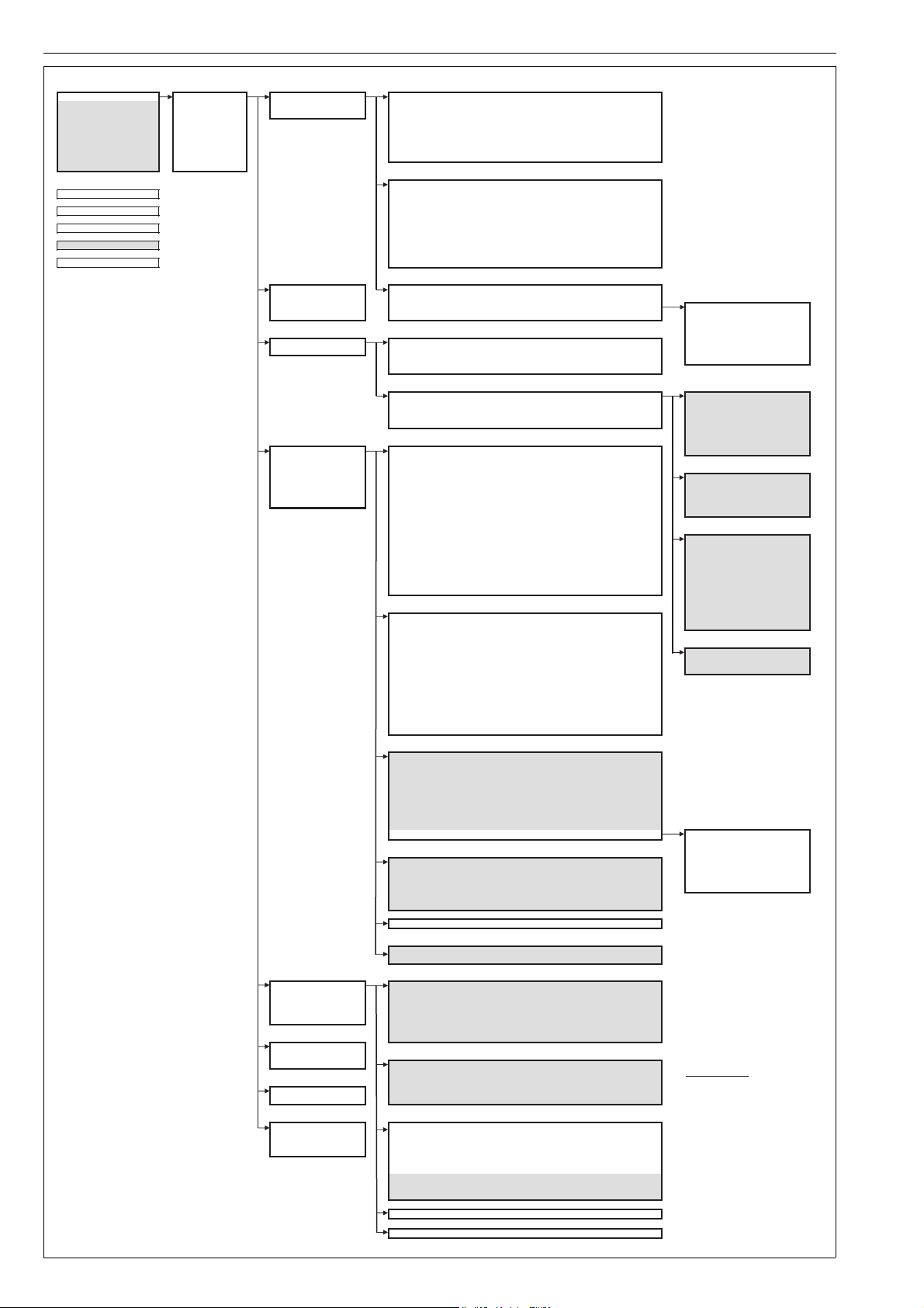
66 7 ND90 71 en
Main Menu: Configuration:
1 Main Menu 1 Configuration 1 Assembly Related 1 Valve Type
Rotary , Linear, NelesCvGlobe, Linear No Comp
2 Input Si gnal 17. 5 mA 2 Calibration s 2 Signal M odification 2 Actuator Type
Double Acting, Single Acting
3 mA-Setpoi nt 84.6 % 3 Valve Offline Tests 3 Flow Modification 3 Valve Rotation Dir.
Clockwise, Counterclockwise
4 Target Setpoint 85.2 % 4 Diagnostics 4 Posit. Fail Action
Fail to Close, Fail to Open
5 Valve Travel 85.2 % 5 Positi oner Informat ion 5 Dead Angle (a0)
0.0 % [0..99%]
6 Temperature 24.7 ºC 6 Units 6 Performance Level
A(1)-Aggressive, b(1)-fast, C(1)-Optimum, d(1)-Stable, E-Max.
stability, (1) = Capac. Booster
7 Supply Pressure 4.9 bar 7 Device Lock 7 DAC Direction Normal Direction, Reverse Direction, DAC Not Installed
8 Pressur e Difference 1. 8 bar 8 Dynamic Variables
1 Bypass Sign. Mod.
No, Yes
2 Signal Dir ection
Open, Close
3 Position Limit Low
0.0% [0..100%]
4 Position Limit High
100.0 % [0..100%]
5 Travel Rate O pen
0.0 %/s [0..1000%/s]
6 Travel Rate Close
0.0 %/s [0..1000%/s]
7 Low Cut-off
2.0 % [0..100%]
8 High Cut-off
100.0 % [0..100%]
9 Split Range Low
0.0 % [0..100%]
Split Range High
100.0 % [0..100%]
Select calibration:
1 Travel Calibr ation 1 Modi fication Type
Linear ( not used), Shape Factor , Custom Table
2 Tuning 2 Shape Factor
<1.0 = quick opening, 1.0 = li near, >1.0 = equal perc ent
3 Travel Calib. and Tuning 3 Predefined C urves 1 Linear
4. 1pt-Calibration 4 User Defined Curve 0.100 % defined in 5% in crements 2 1/25
3 Quick 1/25
Valve Offline Tests: 4 1/33
1 Start Offline Tests 1 Multipoint Step Test 1..10 steps; start position, stop position, init time, duration 5 Quick 1/33
2 Test Key Figures 2 Dynamic Loop Test start position, stop position, init time, ramp time 6 1/50
3 Valve Analysis Test target position, steady time, init time, ramp time 7 Quick 1/50
4 Valve Deadband Test start position, init time, step wait time
1 Start Position 50.0 %
2 End Position 60.0 %
3 Testing Time 12.0 sec.
4 Dead Time Td 2.0 sec.
5 Step Response Time T86 4.4 sec.
Diagnosti cs: 6 Overshoot 12 .3 %
1 Warning Limits 1 Total Oper. Time
216000.0 h [>=0h] 7 Travel Gain -1.2
2 Alarm Limits 2 Valve Total Travel
250000 [>=0]
3 Counters 3 Valve Travel Tren d
2500.0 [>=0]
4 Events 4 Valve Reversals
1000000 [>=0]
1 Start Position 10.0 %
5 Device Status 5 Valve Reversals Trend
10000 [>=0]
2 End Position 100.0 %
6 Alarms Disabled 6 Valve Rev.SSP Trend
5000 [>=0]
3 Total Testing Time 100.0 sec.
7 Device Status 7 Actuat or Total Travel
250000 [>=0] 4 Max. Dyn. Error 0.1 %
8 Actuator Reversals
1000000 [>=0] 5 Setpoint at Error 66.1 %
9 Spool Total Tr avel
10000000 [>=0]
Spool Reversals
10000000 [>=0]
Setpoint Reversals Trend
10000 [>=0]
1 Target Posit ion 50 .0 %
Steady State Dev.
3.0 % [0..100%]
2 Steady Time 1 2.0 sec.
Dynamic St ate Dev.
20.0 % [0..100%]
3 Ramp Time 8.0 sec.
Stiction Low
0.0 bar [0..20bar]
4 Static Hysteresis 1.2 %
Stiction High
4.0 bar [0..20bar]
5 Sensitivity 14.2 %
Load for Open Low
0.0 bar [0..10bar]
6 Load for Opening 0.6 bar
Load for Open High
4.0 bar [0..10bar] 7 Seat Load 0.2 bar
8 SR O2C Close 0.0 bar
9 SR O2C Open 0.0 bar
1 Supply Press. Low Lim.
1.4 bar [1..8bar]
SR C2O Close 0.0 bar
2 Supply Press. High Lim.
8.0 bar [1..8bar] SR C2O Open 0.0 bar
3 Supply Press. Latch Time
30.0 sec. [>0sec]
4 Temp. Low Limit
-40.0 ºC [-40..85ºC]
5 Temp. High Limit
85.0 ºC [-40..85ºC]
1 Start Position 30.0 %
6 Temp. Latch Time
120.0 sec. [>0sec]
2 Testing Time 125.0 sec.
7 Ssdev Alarm Limit
5.0 % [0..100%] 3 Deadband 3.6 %
8 Ssdev. Latch Time
30.0 sec. [>0sec]
9 Stiction Low Limit
0.0 bar [0..20bar]
Stiction High Limit
10.0 bar [0..20bar]
Stiction Latch Nbr
10 [>1]
LfO Low Alarm Limit
0.0 bar [0..10bar]
LfO High Alarm Limit
0.0 bar [0..10bar]
LfO Latch Number
10 [>1]
1 Total Oper. Time 670.23 h
2 Valve Travel 105.42
3 Valve Reversals 223
4 Actuator Travel 105.42
5 Actuator Reversals 223
6 Setpoint Tr avel 115.42
7 Setpoint R eversals 233
8 Spool Valve Travel 279 .38
9 Spool Valve Reversals 843
Reset Counters
1 All events
2 Notify even ts
3 Warn ing events
4 Error even ts
5 Alarm event s
6 Failsaf e events
Device Status: Lists active alerts
Device Status: All alert st atuses by group
Status Group 0, 1, 14, 15, 16, 17,
18, 19, 20, 21, 22, 23
Off / On
Positioner Information: Revision Information:
1 Revision I nformation 1 Device Type ND9100H
2 Serial Numbers 2 Dev id 1375803
3 HART Related 3 Final asmbly num 0
4 Device Mode 4 Universal rev 6
5 Identif y Device 5 Fld dev r ev 3
6 Software rev 174
Units : 7 Hardware rev 1
1 Press. Diff. Unit bar
2 Supply Pressure Unit bar
Serial numbers:
3 Temperature Unit ºC 1 VC Board Snbr. YYW WNNNNBB
2 HART Board Snbr. YYW WNNNNBB Serial Number Format:
Device Lock: 3 Device Serial Nbr. TTYYWWNNNN TT = positioner f actory
1 Device Lock Status … 4 DAC Board HW Rev. H0298 39-1.20 YY = year (last 2 digits)
2 Lock/Unlock Device … 5 DAC Board SW Rev. UNKNOWN W W = week
NNNN = count
Dynamic Variables: HART related: BB = board num ber
PV is … 1 Tag ND9000
SV is … 2 Long tag ND9000
TV is … 3 Date 10/27/2014
QV is … 4 Descriptor ND9000
5 Message ND9000
6 Poll addr. 0
7 Num req pr eams 5
8 Num. r esp preams 5
9 Cfg chng count 134
Device Mode: Auto / Manual
Identify Device: Squawk
Select which counter to reset:
Select one of the Predefined Cur ves
Multipoint Step Test Key Figures:
Dynamic Loop Test Key Figures:
Valve Analysis Test Key Figures:
Valve Deadband Test Key Figures:
7 Event Log
Select which Offline Test to start:
Flow Modification:
Signal Modification:
Assembly Related:
Test Key Figures:
Warning Limits:
Alarm Limits:
Counters:
Events:
1 Valve Travel Cou nters
2 Actuator Travel Counters
3 Setpoint Travel Counters
4 Spool Valve Travel Counters
5 All Trends and Speed Histograms
6 Valve Travel vs. T ime Histogram
1 Multipoint Step Test Key Figures
2 Dynamic Loop Test Key Figures
3 Valve Analysis Test Key Figures
4 Valve Deadband Test Key Figures
ND9100H - Dev v3, DD v3:
MENU
METHOD
Editable variable
Read-only variabl e
in ND9000HT only
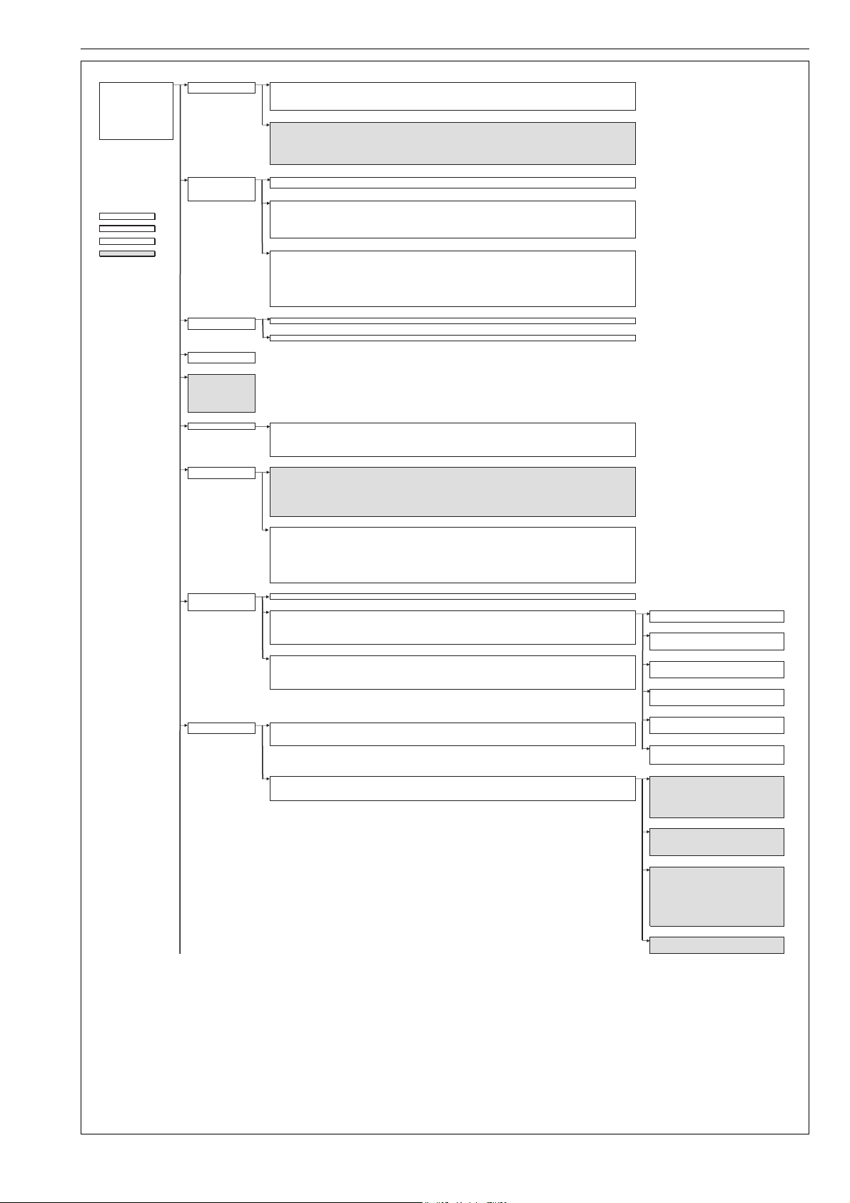
7 ND90 71 en 67
Device Information:
1 Device Information 1 Operation Unit 1 Tag ND9000
2 Confguration 2 Positioner 2 Description ND9000
3 Calibration 3 Date 27.8.2001
4 Manually Stroke Valve 4 Message ND9000
5 Monitoring 5 Long tag ND9000
6 Lifecycle Diagnostic
7 Counter Diagnostics
8 Online Diagnostics 1 Device Type ND9100H
9 Valve Offline Tests 2 VC PCB Serial Number 1650518510
Advanced Co nfiguratio n 3 HART PCB Serial Number 1647317020
4 Device Serial Number PH17100205
5 HART Board HW revision H033592-1.20
6 Software rev 193
7 HART Board Dac SW revision UNKNOWN
Configuration Position Control
1 Position Control Perfor mance Level
Aggressive (A);Fast (b); Op timu m (C); Stable (d); Maximum Stability (E); Capacity Booster, Aggressive (A1); Capacity Booster, Fast
(b1); Capacity Boos ter, Optimum (C1);Capacity Boo ster, Stable (d1)
2 Assembly Related
3 Signal Modification
Assemby Related
1 Actuator Type
Double Acting, Single Acting
2 Valve Acti ng Type
Rotary, Linear with Compensation, nelesCV Globe, Linear without Compensation
MENU
3 Valve Rotation Direction
Clockwise to Close, Counterclockwise to Close
4 Dead Angle (a0) 0,00 %
METHOD
5 Positioner Fail Action
Close, Open
6 Positoner Transmitter Directions
Normal Direction, Reverse Direction, Not Installed
Editable variable
Signal Modification
Read-only variable 1 Direc tion
Rising Setpoint to Open, Rising Serpoint to Close
2 Valve Position Limit LOW 0,00 %
3 Valve Position Limit High 100,00 %
4 Travel Rate Open 0,00 %
5 Travel Rate Close 0,00 %
6 Low Cut-Off 2,00 %
7 High Cut-Off 100,00 %
8 Split Range LOW 0,00 %
9 Split Range HIGH 100,00 %
Bypass si gnal modifica tion
No; Yes
Calibration Automatic Calibration
1 Automatic Calibration 1 Start Automatic Calibration
2 One Point Calibration
One Point Calibration
1 Start One Point Calibration
Manually Strok e Valve
Manual mA Setpoint
Manual percent Setpoint
Monitoring
1 Loop Current
2 Setpoint
3 Target Position
4 Valve Position
5 Device Temperature
6 Supply Pressure
7 Actuator Pressure Difference
Lifecycle Diagnostic Warning Limits for Trends
1 Warning Limits for Trends 1 Stea dy State Deviation 3,00 %
2 Dynamic State Deviation 20,00 %
3 Stiction Low 0.0 bar
4 Stiction High 4.0 bar
5 Load for Open Low 0.0 bar
6 Load for Open High 0.0 bar
Counter Diagnostics Coun ters
1 Counters 1 Total Operation Time 1.10 h
2 Warning Limits for Counters 2 Total Valve Travel 0,04
3 Total Valve Reversals 0
4 Total Actuator Travel 0,04
5 Total Actuator Reversals 0
6 Total Spool Valve Travel 0,02
7 Total Spool Valve Reversals 0
8 Total Setpoint Travel 0,18
9 Total Setpoint Reversals 0
Warning Limits for Counters
1 Total Operation Time 216000.0h
2 Total Valve Travel 250000
3 Total Valve Reversals 1000000
4 Valve Reversals Trend 10000
5 Daily Valve Reversals while Stable Setpoint 5000
6 Total Actuator Travel 250000
7 Total Actuator Reversals 1000000
8 Total Spool Valve Travel 10000000
9 Total Spool Valve Reversals 10000000
Setpoints Reversals Trend 10000
Online Diagnostics
1 Device Status Device Status List active alerts
2 Alarm Limits
3 Events
Alarm Limits Steady State Deviation
1 Steady State Deviation 1 Steady State Deviation High Limit 5 %
2 Supply Pressure 2 Steady State Deviation Latch Time 30sec
3 Temperature
4 Stiction
Supply Pressure
5 Load for Opening 1 Supply Pressure Low Limit 1.4 bar
6 Valve Position 2 Supply Pressure High Limit 8.0 bar
3 Supply Pressure Latch Time 30 sec
Events
1 All Events
Temperature
2 Notify Events 1 Temperature Low Limit -40.0 deg C
3 Warning Events 2 Temperature High Limit 85.0 deg C
4 Error Events 3 Temperature Latch Time 120.0 sec
5 Alarm Events
6 Failsafe events
Stiction
1 Stiction Low Limit 0.0 bar
2 Stiction High Limit 10.0 bar
3 Stiction Latch Number 10
Load for Opening
Valve Offline Tests:
Select which Offline Test to start: 1 Load for Opening Low Limit 0.0 bar
1 Start Offline Tests 1 Multipoint Step Test 2 Load for Opening High Limit 0.0 bar
2 Test Key Figures 2 Dynamic Loop Test 3 Load for Opening Latch Number 10
3 Valve Analysis Test
4 Valve Deadband Test
Valve Positio n
1 Valve Position Low Limit -20.0%
2 Valve Position High Limit 120.0%
3 Valve Position Latch Time 30.0 sec
Test Key Figures: Multipoint Step Test Key Figures:
1 Multipoint Step Test Key Figures 1 Start Position 50.00
2 Dynamic Loop Test Key Figures 2 End Pos ition 5 5.00
3 Valve Analysis Test Key Figures 3 Testing Time 5.00
4 Valve Dea dband Test Ke y Figures 4 Dead Time Td 0.08
5 Step Response Time T86 0.62
6 Overshoot 1.17
7 Travel Gain 1.00
Dynamic Loop Test Key Figures:
1 Start Position 0.00 %
2 End Position 100.00 %
3 Total Testing Time 30.00 sec
4 Max. Dyn. Error 3.67 %
5 Setpoint at Error 87.07 %
Valve Analysis Test Key Figures:
1 Target Position 50.0 %
2 Steady Time 12.0 sec.
3 Ramp Time 30.0 sec.
4 Static Hysteresis 1.2 %
5 Sensitivity 5.2 %
6 Load for Opening 0.6 bar
7 Seat Load 4.8 bar
8 SR O2C Close 0.0 bar
9 SR O2C Open 0.0 bar
SR C2O Close 0.0 bar
SR C2O Open 0.0 bar
Valve Deadband Test Key Figures:
1 Start Position 50,00 %
2 Testing Time 10
3 Deadband 0.1
ND9100H - Dev v4, DD v2:
Operation Unit
Positioner

Metso Flow Control Inc.
Europe, Vanha Porvoontie 229, P.O. Box 304, FI-01301 Vantaa, Finland. Tel. +358 20 483 150. Fax +358 20 483 151
North America, 44 Bowditch Drive, P.O. Box 8044, Shrewsbury, M A 01545, USA. Tel. +1 508 852 0200. Fax +1 508 852 8172
South America, Av. Independéncia, 2500-Iporanga, 18087-101, Sorocaba-São Paulo, Brazil. Tel. +55 15 2102 9700. Fax +55 15 2102 9748
Asia Pacic, 238B Thomson Road, #17-01 Novena Square Tower B, Singapore 307685. Tel. +65 6511 1011. Fax +65 6250 0830
China, 11/F, China Youth Plaza, No.19 North Rd of East 3rd Ring Rd, Chaoyang District, Beijing 100020, China. Tel. +86 10 6566 6600. Fax +86 10 6566 2583
Middle East, Roundabout 8, Unit AB-07, P.O. Box 17175, Jebel Ali Freezone, Dubai, United Arab Emirates. Tel. +971 4 883 6974. Fax +971 4 883 6836
www.metso.com/valves
68 7 ND90 71 en
Advanced Configuration Flow Modification
1 Flow Modification 1 Characterization Type
Shape Factor, Custom Table, Linear(not used)
2 Status Configuration 2 Shape Factor
<1.0 = quick opening, 1.0 = linear , >1.0 = equal percent
3 HART Configuration 3 Init Table with Predefined Curves Linear, 1/25, Quick 1 /25, 1/33, Quick 1/33 , 1/50, Quick 1/50
4 HART Burst Mode Configuration 4 Us er Defined Curve 0.100% defined in 5% increments
5 Reset
6 Write Protection
Status Configuration Manage All Statuses
1 Manage All Sta tuses Enable All Statuses
2 Reduced Performance ON Disable All Statuses
3 Calibrat ion Reco mmended ON
4 Valve Position Low Limt Exceeded ON
5 Valve Position High Limit Exceeded ON
6 Pressure Sensor 1 Failure Detected ON
7 Pressure Sensor 2 Failure Detected ON
8 Pressure Sensor 3 Failure Detected ON
9 Spool Valve Sensor Failure Detected ON
Temperature Sensor Failure Detected ON
Continued Pr ocesso r Reset Detecte d ON
Position S ensor Fa ilure Detec ted ON
Position Sensor Out of Range Detected ON
Input Signal Senso r Failure D etected ON
Prestage Shortcut Detec ted ON
Prestage Cut Detected ON
Steady State Deviation Trend Limit Exceeded ON
Dynamic State Deviation Limit Exceeded ON
Stiction Trend Low Limit Exceeded ON
Stiction Trend High Limit Exceeded ON
Load for Opening Trend L ow Limit Exce eded ON
Load for Opening Trend H igh Limit Exc eeded ON
Total Operation Time Limit Exceeded ON
Total Valve Travel Limit Exceeded ON
Total Valve Reversals Limit Exceeded ON
Total Actuator Travel Limit Exceeded ON
Total Acuator Reversals Limit Exceeded ON
Total Spool Valve Travel Limit Exceeded ON
Total Spool Valve Reversals Limit Excee ded ON
Daily Setpoi nt Revers als Trend L imit Exceede d ON
Daily Valve Reversals Trend Limit Exceeded ON
Daily Valve Reversals while Stable Setpoint Trend Limit Exceeded ON
Supply Pressure Limit Exceeded ON
Temperature Limit Exceeded ON
Hunting Dete cted ON
Steady State Deviation Limit Exceeded ON
Stiction Low Limit Exceeded ON
Stiction High Limit Exceeded ON
Load for Opening Low Limit Exceeded ON
Load for Opening High Li mit Exceede d ON
Spool Va lve Proble m Detec ted ON
Pneumati cs Pro blem Det ected ON
Friction Problem Detected ON
Supply Pressure Too Low for Single Acting Actuator . ON
Hart Configuration Preambles
1 Preambles 1 Num re sp prea ms 5
2 Dynamic Variables
3 Pressure Unit bar , PSI
Dynamic Variables
4 Temperature Unit Celsius, Fahrenheit 1 1st Dyn Var
2 2nd Dyn Var
3 3rd Dyn Var
4 4st Dyn Var
HART Burst Mode Configuration Burst Mode Variables
1 Burst Mode Variables 1 Burst Mode Off
2 Burst Command Cmd 3: Dyn vars/current
3 1st Burst Var. Setpoint
4 2nd Burst Var. Valve Position
5 3rd Burst Var. Device Temperature
6 4th Burst Var. Actuator Pressure Difference
Reset
1 Reset Statistics
Valve Travel and Reversals; Actuator Travel and Reversals; Setpoint Travel and Reversals; Spool Valve Travel and Reversals; Trends;
Valve Travel Histogram; Event Log; Reset All
2 Reset Configura tion Changed Fla g No, Yes
Write Protection
1 Device is locked OFF
2 Lock is permanent OFF
3 Locked by a primary master OFF
4 Lock/Unlock Device Unlock, Lock Temporarily, Lock Permanently
Fig 2 ND9000H 0402 Menu Tree
 Loading...