

Metso MA050L, MA080L, MA150L, MA200L, MT050J Installation Maintenance And Operating Instructions
...
BALL VALVE
Series MBV
P&P version
Installation, Maintenance and
Operating Instructions
1 MBV 75 en
Issue 5/02

2
Table of Contents
1 GENERAL. . . . . . . . . . . . . . . . . . . . . . . . . . . 3
1.1 Scope of the manual . . . . . . . . . . . . . . . . . . . . 3
1.2 Valve description . . . . . . . . . . . . . . . . . . . . . . . 3
1.3 Markings . . . . . . . . . . . . . . . . . . . . . . . . . . . . . . 3
1.4 Specifications . . . . . . . . . . . . . . . . . . . . . . . . . . 4
1.5 Valve approvals . . . . . . . . . . . . . . . . . . . . . . . . 4
1.6 CE marking . . . . . . . . . . . . . . . . . . . . . . . . . . . . 4
1.7 Recycling and disposal of a rejected valve . . . . 4
1.8 Safety precautions . . . . . . . . . . . . . . . . . . . . . . 5
2 TRANSPORTATION, RECEPTION
AND STORAGE . . . . . . . . . . . . . . . . . . . . . 5
3 INSTALLATION AND USE. . . . . . . . . . . . 6
3.1 General . . . . . . . . . . . . . . . . . . . . . . . . . . . . . . . 6
3.2 Installing in the pipeline . . . . . . . . . . . . . . . . . 6
3.3 Actuator . . . . . . . . . . . . . . . . . . . . . . . . . . . . . . 6
3.4 Commissioning. . . . . . . . . . . . . . . . . . . . . . . . . 6
4 SERVICING . . . . . . . . . . . . . . . . . . . . . . . . . 7
4.1 General . . . . . . . . . . . . . . . . . . . . . . . . . . . . . . . 7
4.2 Changing the gland packing while
the valve is in the pipeline . . . . . . . . . . . . . . . 7
4.3 Repair of a jammed or stuck valve
while it is in the pipeline . . . . . . . . . . . . . . . . . 8
4.4 Detaching the actuator . . . . . . . . . . . . . . . . . . 8
4.5 Removing the valve from the pipeline . . . . . 8
4.6 Dismantling the valve . . . . . . . . . . . . . . . . . . . 8
4.6.1 Sizes DN 25-40, 65 . . . . . . . . . 8
4.6.2 Sizes DN 50-400 . . . . . . . . . . . 9
4.7 Inspection of removed parts . . . . . . . . . . . . . 9
4.8 Replacing parts. . . . . . . . . . . . . . . . . . . . . . . . . 9
4.9 Assembly. . . . . . . . . . . . . . . . . . . . . . . . . . . . . 10
4.9.1 Sizes DN 25-40, 65 . . . . . . . . 10
4.9.2 Sizes DN 50-400 . . . . . . . . . . 10
5 TESTING THE VALVE. . . . . . . . . . . . . . . 11
6 INSTALLING THE ACTUATOR. . . . . . . 11
6.1 General . . . . . . . . . . . . . . . . . . . . . . . . . . . . . . 11
6.2 Installing the M-series handwheel operator 11
6.3 Installing the B1C-series actuator. . . . . . . . . 11
6.4 Installing the B1J-series actuator. . . . . . . . . . 12
6.4.1 B1J-type . . . . . . . . . . . . . . . 12
6.4.2 B1JA-type . . . . . . . . . . . . . . 12
6.5 Installing other makes of actuators . . . . . . . 12
7 MALFUNCTIONS . . . . . . . . . . . . . . . . . . . 12
8 TOOLS. . . . . . . . . . . . . . . . . . . . . . . . . . . . . 12
9 ORDERING SPARE PARTS. . . . . . . . . . . . 12
10 EXPLODED VIEW AND PARTS LIST. . . 13
11 DIMENSIONS AND WEIGHTS . . . . . . . . 14
11.1 DN 25-40, 65, PN 40 . . . . . . . . . . . . . . . . . . 14
11.2 DN 50-200, PN 10, 16 . . . . . . . . . . . . . . . . . 14
11.3 DN 25-40, 65 with hand lever LR . . . . . . . . 15
11.4 DN 50-100 with hand lever LR . . . . . . . . . . 15
11.5 With hand wheel operator M. . . . . . . . . . . . . 16
11.6 DN 25-40, 65 with pneumatic actuator B1C 17
11.7 DN 50-300 with pneumatic actuator B1C . 18
11.8 DN 25-40, 65 with pneumatic
spring-return actuator B1J . . . . . . . . . . . . . . . 20
11.9 DN 50-300 with pneumatic
spring-return actuator B1J . . . . . . . . . . . . . . . 21
12 TYPE CODE . . . . . . . . . . . . . . . . . . . . . . . . 23
READ THESE INSTRUCTIONS FIRST!
These instructions provide information about safe handling and operation of the valve.
If you require additional assistance, please contact the manufacturer or manufacturer’s representative.
Addresses and phone numbers are printed on the back cover.
SAVE THESE INSTRUCTIONS!
Subject to change without notice.
All trademarks are property of their respective owners.

1 GENERAL
1.1 Scope of the manual
This installation, operation and maintenance manual provides
essential information on M-series ball valves. The actuators and
instrumentation to be used with M-series valves are also discussed briefly. Refer to the separate actuator and control equipment instruction manuals for further information.
NOTE:
Selection and use of the valve in a specific application requires
close consideration of detailed aspects. Due to the nature of the
product, this manual cannot cover all the individual situations that
may occur when installing, using or servicing the valve.
If you are uncertain about the use of the valve or its suitability for
your intended use, please contact Metso Automation for more
information.
1.2 Valve description
M-series valves are flanged full bore ball valves. The valve body
is in two parts, fastened together by body-joint bolting. In sizes
DN 25-40, 65 the valve body is in one part; the ball and the seats
are fastened behind a screw-on insert
The ball and stem are separate. Stem blow-out is prevented by
a shoulder machined on the stem.
The valve is either soft or metal seated. Stem torque is transmitted to the ball through a spline driver installed in a groove on
the ball surface. In sizes DN 25-40, 65 the stem is installed straight
into a groove on the ball surface.
The valve is tight in both flow directions. Tightness is provided
by a pressure differential which forces the ball up against the
downstream seat.
Construction details of individual valves are included in the type
code shown on the valve identification plate. To interpret the
type code, please refer to the type coding key in this manual.
M-series valves are specially designed for demanding shut-off
applications involving high operation cycles. They can also be
used in flow control applications.
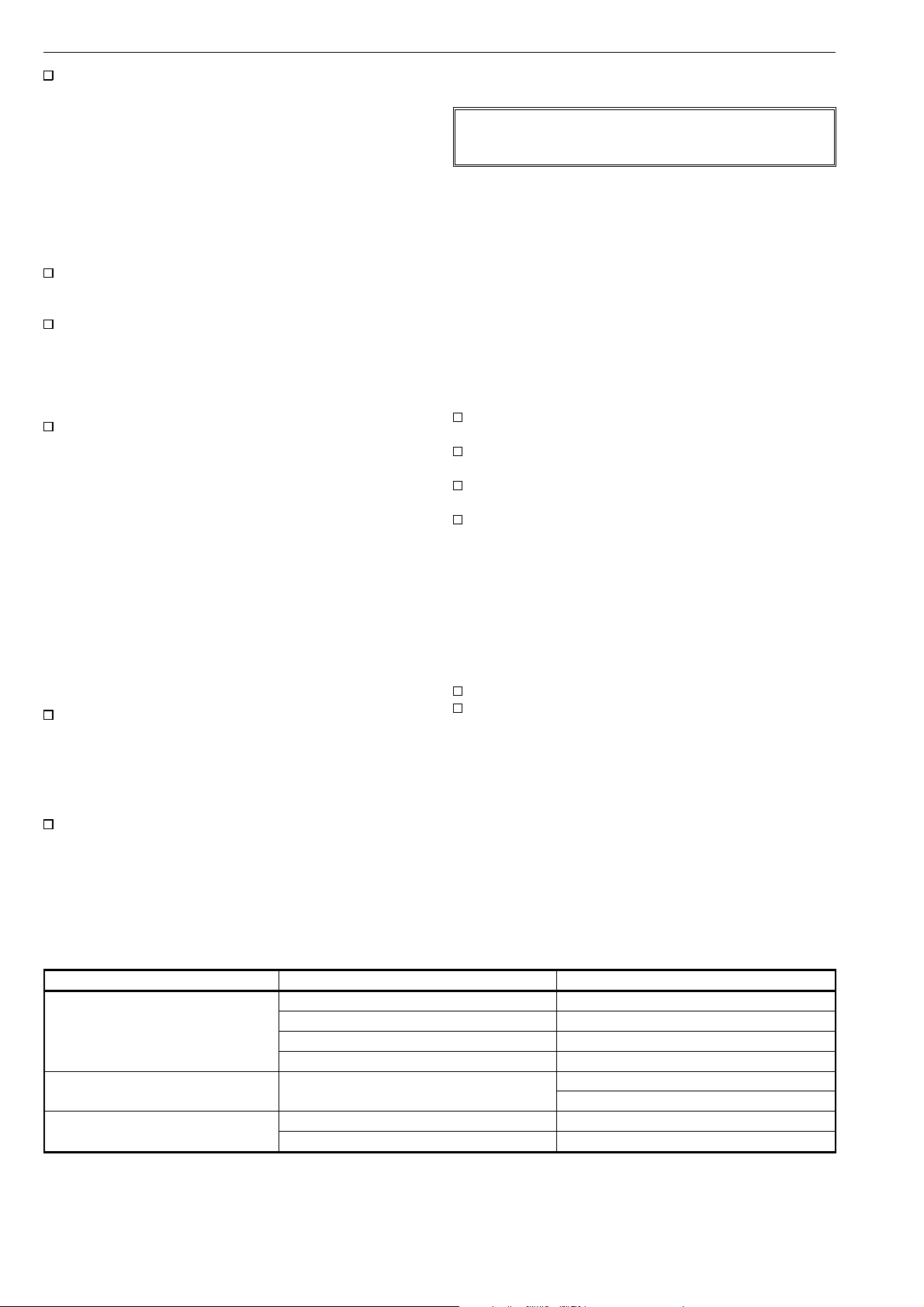
Fig. 2. Construction of an M series, sizes, sizes DN 50-400
1.3 Markings
Body markings are cast or stamped on the body (see Fig. 3).
The identification plate (Fig. 4) is attached to the flange.
ID plate
Nominal size,
Batch no.
N-J mark,
body material
pressure rating
Fig. 3. Valve markings
Identification plate markings are:
1. Body material
2. Shaft material
3. Trim material
4. Seat material
5. Max and min operating temperature
6. Max shut-off pressure differential / temperature
7. Pressure class
8. Type designation
9. Valve manufacturing parts list no.
10. Model
Body
material
3
Fig. 1. Construction of an M series, sizes DN 25-40, 65
(2)
(1)
ATTENTION : READ INSTRUCTIONS BEFORE INSTALLATION OR SERVICING. CONTACT METSO AUTOMATION FOR COPY.
SHAFT
BODY
TRIM
SEAT
(4)
(5)
T max
MAX. OPER. psatRATING TYPE
T min
(6)
(7)
Fig. 4. Identification plate
(8)
MADE BY METSO AUTOMATION
No.
(9)(3)
MOD
(10)
0045

4
1.4 Specifications
Face-to-face length: acc. to ISO 5752
Body rating: DIN PN 10, 16, 25, 40
Max. pressure differential: see Figs. 7 and 8
Temperature range: see Figs. 5 and 6
Flow direction: free
Tightness:
metal seated DIN 3230 rate 2,
ISO 5208 leakage rate D
soft seated ISO 5208 leakage rate A
Dimensions: see tables on pages 15–23
Weights: see tables on pages 15–23
Fig. 7. Allowed differential pressures, soft seated
Fig. 5. Pressure/temperature curve of valve body,
W. no. 1.4408
Fig. 6. Pressure/temperature curve of valve body,
W. no. 1.0619
Fig. 8. Allowed differential pressures for operation, metal
seated, PN 40. Smaller sizes are full rated.
1.5 Valve approvals
M-series ball valves meet the requirements set by DIN 3840 and
BS 5351.
Fire safety characteristics are designed according to API 607 and
BS 6755.
A patent application for the valve design has been filed.
1.6 CE marking
The valve meets the requirements of the European Directive
97/23/EC relating to pressure equipment, and has been marked
according to the Directive.
1.7 Recycling and disposal of a rejected valve
Most valve parts can be recycled if sorted according to material.
Most parts have material marking. A material list is supplied with
the valve. In addition, separate recycling and disposal instructions are
available from the manufacturer. A valve can also be returned to
the manufacturer for recycling and disposal against a fee.

5
1.8 Safety precautions
CAUTION:
Do not exceed the valve performance limitations!
Exceeding the limitations marked on the valve may cause
damage and lead to uncontrolled pressure release.
Damage or personal injury may result.
CAUTION:
Do not dismantle the valve or remove it from the
pipeline while the valve is pressurized!
Dismantling or removing a pressurized valve will result in
uncontrolled pressure release. Always isolate the relevant
part of the pipeline, release the pressure from the valve and
remove the medium before dismantling the valve.
Be aware of the type of medium involved. Protect people and
the environment from any harmful or poisonous substances.
Make sure that no medium can enter the pipeline during valve
maintenance.
Failure to do this may result in damage or personal injury.
CAUTION:
Beware of the ball cutting movement!
Keep hands, other parts of the body, tools and other objects
out of the open flow port. Leave no foreign objects inside the
pipeline. When the valve is actuated, the ball functions as a
cutting device. Close and detach the actuator pressure supply
pipeline for valve maintenance. Failure to do this may result
in damage or personal injury.
2 TRANSPORTATION, RECEPTION
AND STORAGE
Check the valve and the accompanying device for any damage
that may have occurred during transport.
Store the valve carefully. We recommend storing indoors in a
dry place.
Fig. 9. Storing the valve
Do not remove the flow port protectors until installing the valve.
Move the valve to its intended location just before installation.
The valve is usually delivered in the open position.
CAUTION:
Beware of noise emission!
The valve may produce noise in the pipeline. The noise level
depends on the application. It can be measured or calculated
using the Metso Automation Nelprof computer program.
Observe the relevant work environment regulations on noise
emission.
CAUTION:
Beware of extreme temperatures!
The valve body may be very hot or very cold during use.
Protect people against cold injuries or burns.
CAUTION:
When handling the valve or the valve package, bear
in mind its weight!
Never lift the valve or valve package by the actuator, positioner, limit switch or their piping.
Place the lifting ropes securely around the valve body (see Fig. 10).
Damage or personal injury may result from falling parts.
The weights are shown on pages 14–22.
CAUTION:
Follow the proper procedures when handling and
servicing oxygen valves.
CORRECT
WRONG
Fig. 10. Lifting the valve

6
3 INSTALLATION AND USE
3.1 General
Remove the flow bore protectors and check that the valve is
clean inside. Clean the valve if necessary.
3.2 Installing in the pipeline
CAUTION:
When handling the valve or the valve package as a
whole, bear in mind the weight of the valve or the
entire package!
Flush the pipeline carefully before installing the valve. Make sure
the valve is entirely open when flushing. Foreign particles, such
as sand or pieces of welding electrode, will damage the ball and
seats.
NOTE:
Use screws, nuts, bolts and gaskets equivalent to the fastenings
used elsewhere in the pipeline. Center the flange gaskets
carefully when fitting the valve between flanges.
NOTE:
Do not attempt to correct pipeline misalignment by means of
flange bolting.
The valve may be installed in any position and offers tightness in
both directions. However we do not recommend installing the
valve with the actuator on the underneath side because dirt in
the pipeline may then enter the body cavity and damage the
gland packing. The position to be avoided is shown in Fig. 11.
Fig. 12. Supporting the valve
3.3 Actuator
NOTE:
When installing the actuator on the valve, make sure that the
valve package functions properly. Detailed information on
actuator installation is given in section 6 or in the separate
actuator instructions.
The valve open/closed position is indicated as follows:
by an indicator on the actuator
or
by a groove at the end of the ball stem (parallel to the ball
flow opening).
If there is any uncertainty about the indicator, check the ball
position by the groove.
The actuator should be installed in a manner that allows plenty
of room for its removal.
The upright position is recommended for the actuator cylinder.
The actuator must not touch the pipeline, because pipeline
vibration may interfere with its operation.
Fig. 11. Avoid this mounting position
It may be necessary to firmly support the pipeline in order to
protect the valve from excess stress. Sufficient support will also
reduce pipeline vibration and thus ensures proper functioning of
the positioner.
To facilitate servicing, it is preferable that the valve be supported
by the body, using pipe clamps and supports. Do not fasten
supports to the flange bolting or to the actuator, see Fig. 12.
In certain cases it may be considered advantageous to provide
additional support to the actuator. These cases will normally be
associated with large actuators, extended stems, or where severe
vibration is present. Please contact Metso Automation for advice.
3.4 Commissioning
Ensure that there is no dirt or foreign objects left inside the valve
or pipeline. Flush the pipeline carefully. Make sure that the valve
is entirely open when flushing.
Ensure that all nuts, pipings, and cables are properly fastened.
Check that the actuator, positioner, and switch are correctly
adjusted. Actuator adjustment is explained in section 6. To adjust
the accompanying device refer to the separate control equipment instruction manuals.
7
4SERVICING
4.1 General
CAUTION:
Observe the safety precautions mentioned in section 1.8 before servicing!
CAUTION:
When handling the valve or the valve package as a
whole, bear in mind the weight of the valve or the
entire package!
NOTE:
Always use original spare parts to make sure that the valve
functions as intended.
Although M-series ball valves require no regular maintenance, it
is recommended that the gland packing be checked regularly for
tightness. If for some reason the valve should require maintenance, then a few simple service measures should normally
suffice. This section outlines the service operations that can be
carried out by the end user.
The numbers in parentheses refer to the parts list and the exploded
view of the valve on page 13, if not otherwise stated.
V-ring packings:
Fasten the gland follower (9) and tighten the nuts (18)
with hands at first and then with a tool 1.5–2 turns.
Graphite packings:
Fasten the gland follower (9); place the nuts (18) on the
studs (14) and tighten them to torques shown in Table 1.
Check leakage when the valve is pressurized and retighten the nuts carefully if necessary.
Table 1. Recommended tightening torques of the packing nuts
Valve size, DN 25-40, 65 50-100 150 200-400
Torque, Nm 10 20 50 90
NOTE:
If you choose to send the valve to the manufacturer for
servicing, do not dismantle it. Instead, clean the valve carefully
of all medium and inform the manufacturer of any dangerous
medium involved.
4.2 Changing the gland packing while the
valve is in the pipeline
CAUTION:
Do not dismantle the valve or remove it from the
pipeline while the valve is pressurized!
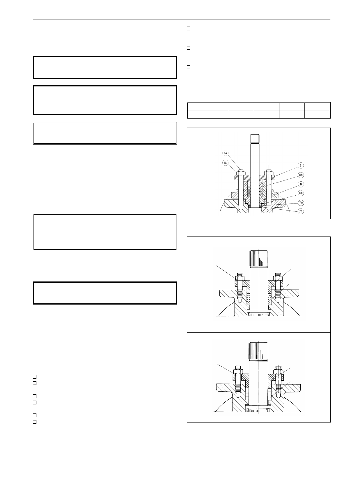
The V-ring gland packing requires no regular tightening. The gland
packing tightness is provided by the pipeline pressure together
with gland pressure against the packing rings. In graphite gland
packings, tightness is ensured by contact between the gland
follower and the packing rings.
The gland packing (69) must be changed if leakage occurs even
after the hex nuts (18) have been tightened. The V-ring gland
packing must be tightened with care because excess force may
damage the V-rings.
Make sure that the valve is not pressurized.
Detach the actuator, coupling, and bracket according to
the instructions in section 4.4.
Remove the gland follower (9).
Remove the packing rings (69) from around the stem using
a knife or some other pointed instrument.
Clean the packing ring counterbore.
Place the new packing rings (69) over the stem (5). The
gland follower may be used for pushing the rings into the
counterbore. Do not damage packing rings in the stem
splines. See Figs. 13 and 14 for proper orientation.
Fig. 13. Gland packing, sizes DN 25-40, 65
hex nut (18)
hex nut (18)
Fig. 14. Gland packing, sizes DN 50-400
gland follower (9)
gland packing (69)
(V-rings)
gland follower (9)
gland packing (69)
(graphite)

8
4.3 Repair of a jammed or stuck valve
while it is in the pipeline
Jamming may be due to the ball (3) and seats (7) becoming
clogged with flow medium. They may be cleaned by turning the
ball to the partly open position and flushing the pipeline. If this
does not help, follow the instructions in the following sections.
4.4 Detaching the actuator
CAUTION:
When handling the valve or the valve package as a
whole, bear in mind the weight of the valve or the
entire package!
NOTE:
Before dismantling, carefully observe the position of the valve
with respect to the actuator and positioner/limit switch so as
to make sure that the package can be properly re-assembled.
It is generally most convenient to detach the actuator before
removing the valve from the pipeline. If the valve is small or if it
is difficult to access, it may be more practical to remove the entire
package at the same time.
Note that the seats can be replaced without detaching the
actuator.
Close and detach the actuator pressure supply pipeline
and remove control cables.
Unscrew the bracket screws.
Detach the actuator. The actuator can be removed by
hand or with a special tool made for this purpose. The
tool can be ordered from the manufacturer (see section
"Tools").
Remove the bracket and coupling.
4.5 Removing the valve from the pipeline
CAUTION:
Do not dismantle the valve or remove it from the
pipeline while the valve is pressurized!
Make sure that the valve is not pressurized and that the
pipeline is empty. Make sure that the medium cannot flow
into the section where servicing is to take place.
Support the valve carefully with a hoist. Place ropes
carefully and unscrew the pipe flange bolts. See that the
ropes are positioned correctly, see Fig. 10. Lift valve
down.
4.6 Dismantling the valve
4.6.1 Sizes DN 25-40, 65
Place the valve in a standing position on the pipe flange
end so that the body cap points upwards. Use a level
surface that will not scratch the pipe flanges.
Unfasten the gland follower (9) nuts. Remove the gland
follower and the packing rings (69).
Unfasten the bolts of the stem retainer (8). Remove the
gland, the stem retainer seal (66), the stem (5) and the
thrust bearings (70, 71).
Unscrew the insert (2) using a suitable tool. See section 8
"Tools". Remove the ball (3) and seats.
Remove the locked seat (7) using a special tool that can
be ordered from the manufacturer, see Fig. 16.
Fig. 15. Removing the actuator with an extractor
Fig. 16. Removing the locked seat

9
4.6.2 Sizes DN 50-400
Place the valve in a standing position on the pipe flange
end. Use a level surface that will not scratch the flanges.
See that the body stud nuts (16) are facing upward.
Mark the the body halves for correct orientation during
re-assembly.
Turn the ball to the closed position.
Unscrew the body stud nuts (16).
Remove the body cap (2). If the seat (7) is not lying on
the ball (3), prevent the seat from falling from the body
cap and detach it later. Don’t leave your fingers
between the body cap and the surface!
Stand the removed body cap on its pipe flange. See Fig. 17.
Lift the ball (3) from the body (1) by gripping by the flow
bore (small sizes) or by passing a rope through the flow
bore and turning it at the same time around the flow bore
axis. Handle the ball carefully and place it on a soft surface.
See Fig. 19.
Pull the spline driver (4) from the stem (5) and remove
the seat (7) from the lower body half (1).
Remove the gland follower (9).
Push the stem into the body and remove it.
Remove thrust bearing(s) (70), secondary stem seal (71),
packing rings (69) and body gasket (65). Also remove back
seals (63) in ball seats.
Fig. 17. Lifting the body cap
Remove the seat from body cap if it is still in place. If the
seat is locked, it must be removed using a special tool (see
Fig. 18 and section "Tools").
Fig. 18. Removing the locked seat
Fig. 19. Removing of the ball
4.7 Inspection of removed parts
Clean removed parts.
See if the stem (5) or thrust bearings (70) are damaged.
See if the ball (3) or seats (7) are damaged (scratched) by
examining them under bright light. The ball and the seat
can be replaced if necessary.
See if the body joint flanges are damaged.
4.8 Replacing parts
We recommend that soft material parts be replaced whenever
the valve is dismantled for servicing. Other parts may be replaced
if necessary. Always use genuine spare parts to ensure proper
functioning of the valve (see section "Ordering spare parts").

10
4.9 Assembly
4.9.1 Sizes DN 25-40, 65
Place the valve in a standing position on the pipe flange
end so that the insert thread points upwards. Use a level
surface that will not scratch the flanges.
Screw the insert (2) into the body by itself. Tighten the
insert slightly to ensure that it has gone all the way in. Mark
the position, for example by tapping a screwdriver lightly
against the body at the point of the mark in the insert.
Unscrew the insert and remove it from the body.
H seat: Place the back seal (63) into the seat (7), see Fig. 20,
and then both parts all the way into the body counterbore.
H seat: Lock the seat into the body using a special tool
that can be ordered from the manufacturer. The tool is
accompanied by operating instructions.
T / M seat: Place the seat (7) into the body counterbore.
62
63
7
Fig. 20. Mounting the back seal, H seat
25
Push the packing rings (69) into their place in the stem
retainer (8).
Tighten the studs (14). Place the gland follower (9) on the
packing rings (69). Lightly screw the nuts (18) onto the
studs (14).
Cycle the valve slowly a couple of times to ensure that
the ball’s position between the seats is correct.
Tighten the gland follower nuts (10 Nm), see also section 4.2.
Check the gland packing for leakage when the valve is
pressurized and re-tighten the nuts carefully if necessary.
Install the valve in the pipeline as carefully and accurately as
when you removed it. Note the instructions given in section 3.
4.9.2 Sizes DN 50-400
Place the valve body on the pipe flange end. Use a level
surface that will not scratch the flanges.
S / K seat: Place the back seals (63) into the seats (7) as
shown in Fig. 22. Place one of the seats into the body
counterbore.
75
76
H seat: Place the back seal (63), Fig. 22, and the seat (7)
into body counterbore.
K / H seat: Lock the seat (7) using a special locking tool.
The tool is accompanied by operating instructions.
T / M seat: Place the seat (7) into body counterbore.
Slip the thrust bearing(s) (70) and secondary stem seal (71)
onto the stem (5). See exploded view for proper orientation.
Push the stem into body (1) from the inside and assemble the
gland packing (69) from the outside. Place the gland follower (9)
over the stem (5). Tighten the gland nuts (18) with fingers.
1, 2
7
grooves towards
the ball
Fig. 21. Mounting the T / M seat
Place the ball on the locked seat so that the groove faces
the stem entrance opening. Push the stem into the valve
from the outside. Make sure that the end of the stem (5)
fits into the ball groove.
H seat: Assemble the seat (25), spring (62), back seals (75)
and back-up ring (76), Fig. 20, and place the assembly on
the insert (2).
T / M seat: Place the seat (7) on the ball (3), see Fig. 21.
Slip the thrust bearings (70, 71), part (70) first, onto the
stem and push them against the stem shoulder.
Put the stem retainer seal (66) in its groove, replace the
stem retainer (8) and tighten the studs (13).
Tighten the nuts (17) of the studs (13) evenly to achieve
uniform compression of the seal (66). The torque is 25
Nm when the threads have been lubricated.
Place the body gasket (65) into the body, on the shoulder
at the foot of the threads.
Screw the insert and seat assembly into the body. This is
easier to do if the valve is horizontal. Tighten the insert
using a spanner wrench until the cap reaches 5-10 mm
past the mark made earlier. The torque is 160 Nm for
DN 25 and 200 Nm for DN 40.
1
S / K seat
63
7
H seat
63
62
76
75
Fig. 22. Mounting the back seal, S / K and H seats
Slip the spline driver (4) onto the stem. Note the correct
orientation. Place the ball into the body (1) carefully.
K seat: Place another seat (with the back seal) into the
body cap (2) as described above. Lock the seat
S seat: Place the seat on the top of the ball.
H seat: Place the back seal (75), back-up ring (76), spring (62),
Fig. 21, and the seat (7) into body cap.
T / M seat: Place the seat (7) onthe ball.
Install the body gasket (65) in the body groove.
Place the body cap (2) carefully over body studs (12) and
body (1). See that flange holes are aligned acc. to the mark
made during the dismantling.
Fasten the body nuts (16). Tighten the nuts gradually,
always switching to other side of the valve after every nut.
The recommended torques are given in Table 2.
2

11
Table 2. Recommended tightening torques of the body stud nuts
Recommended tightening torques (Nm)
Thread Stainless steel Carbon steel
M14 55-63 55-63
M16 114-133 118-140
M20 173-203 184-214
M22 214-251 280-329
M24 310-360 490-580
M30 388-454 626-738
NOTE: Threads must be well lubricated. If studs and nuts are
unlubricated and have been used before, torques must be
about 50% higher.
Cycle the valve slowly a couple of times to insure correct
position of the ball between the two seats. The spline
driver should move correctly too.
Tighten the gland nuts (18) with fingers at first and then
with a tool 1.5–2 turns. Check for leakage once the valve
is pressurized and re-tighten the nuts carefully if necessary.
Install the valve in the pipeline as carefully and accurately
as when removing it. Follow the instructions given in
Section 3.
5 TESTING THE VALVE
Bracket with ISO
5211 mounting
surface
Stem
Coupling
Fig. 23. Bracket and coupling mounted on valve
Adjust the circular movement of the ball with the hexagon
screws located at the side of the housing (see figure 24).
The stop-screw for the open position is nearest to the
handwheel on the side of the housing and the screw for
the closed position is at the opposite end. The turning
directions for the handwheel are marked on the wheel.
Check the handwheel by turning the valve to the extreme
positions. The yellow arrow should indicate the direction
of the ball flow bore.
CAUTION:
Pressure testing should be carried out using equipment conforming to the correct pressure class!
We recommend that the valve body be pressure tested after
the valve has been assembled.
The pressure test should be carried out in accordance with an
applicable standard using the pressure rating required by the
pressure class or flange bore of the valve. The valve must be in
an open position during the test.
If you also want to test the tightness of the closure member,
contact the manufacturer.
6 INSTALLING THE ACTUATOR
6.1 General
Different Metso Automation actuators can be mounted using
suitable brackets and couplings. The valve can be actuated by an
M-series handwheel operator or B1-series actuators.
6. 2 Installing the M-series handwheel operator
The mark at the end of the stem indicates the direction
of the ball flow bore. Turn the valve to the closed position.
Lubricate the grooves of the actuator and the couplings.
Place the coupling on the stem and lock it. Place the bracket
on the valve and turn the lubricated screws a few times.
Turn the actuator to the closed position and push it
carefully onto the valve stem on which the coupling has
been mounted. Please note the marks on the handwheel
and the coupling.
Lubricate the actuator screws. Tighten all screws.
stop-screw for CLOSED position
stop-screw for OPEN position
Fig. 24. Open and closed positions of the M-series actuator
6.3 Installing the B1C-series actuator
CAUTION:
Beware of ball cutting movement!
Turn the valve to the closed position and drive actuator
piston to the extreme outward position.
File off any burrs and clean the stem bore .
Place the coupling over the stem (see Fig. 23). Note the
correct position. The line at the end of the stem and
coupling indicates the direction of the ball flow bore.
Lubricate the coupling and stem bore. Fasten the bracket
loosely to the valve.
Slip the actuator carefully onto the coupling. Avoid forcing
it since this may damage the ball and seats. We recommend mounting the actuator so that the cylinder is pointing upwards.
Position the actuator parallel or vertical to the pipeline as
accurately as possible. Lubricate the actuator mounting
screws and then fasten all screws.
12
Adjust the ball open and closed positions by means of the
actuator stop screws located at both ends (see Fig 24).
An accurate open position can be seen in the body flow
bore. Check that the yellow arrow on the actuator indicates the ball flow opening position. Keep fingers out
of the flow bore!
There is no need for stop screw adjustment if the actuator is
re-installed in the same valve. Drive actuator piston to the
housing end (open position). Turn the actuator by hand until the
valve is in the open position. Fasten the actuator in this position
as explained above.
Check the stop screw thread tightness. The threads must
be sealed using an appropriate non-hardening sealant, e.g
Loctite 225.
Check that the actuator is functioning correctly. Drive the
actuator piston to both cylinder ends and check the ball
position and its movement with respect to the actuator
(close: clockwise; open: counterclockwise). The valve
should be closed when the piston is in the extreme
outward position.
If necessary, change the position of the actuator pointing
cover to correctly indicate the valve open/closed position.
6.4 Installing the B1J-series actuator
Spring-return actuators are used in applications where valve
opening or closing movement is needed in case the air supply is
interrupted. The B1J type is used for spring-to-close operation;
the spring pushes the piston towards the cylinder end, the
extreme outward position. In turn, the B1JA type is used for
spring-to-open operation; the spring pushes the piston towards
the housing.
Spring-return actuators are installed in a manner similar to
B1C-series actuators, taking into account the following.
6.4.1 B1J-type
Install the actuator so that the piston is in the extreme
outward position. The cylinder must not be pressurized
and air supply connections must be open. The valve must
be in the closed position.
6.5 Installing other makes of actuators
NOTE:
Metso Automation accepts no responsibility for compatibility
of actuators not installed by Metso Automation.
Other actuators can be installed only if they have an ISO 5211
actuator connection.
7 MALFUNCTIONS
The following Table 3 lists malfunctions that might occur after
prolonged use.
8 TOOLS
In addition to standard tools, the following special tools are
needed.
For removal of the actuator:
- extractor
For removal of the insert:
- removal tool
For removal of the locked seats:
- detaching tool
For locking of the seats:
- locking tool
These tools can be ordered from the manufacturer. Always give
the valve type designation when ordering.
9 ORDERING SPARE PARTS
When ordering spare parts, always include the following information:
valve type designation (from the name plate or documents)
number of the parts list (or number of this manual), part
number, name of the part and number of pieces required.
6.4.2 B1JA-type
Install the actuator so that the piston is in the cylinder end
position at housing side. The cylinder must not be pressurized and air supply connections must be open. The
valve must be in the open position.
The rest of the installation procedure is the same as in section 6.3.
Table 3. Possible malfunctions
Symptom Possible fault Toimenpiteet
Leakage through a closed valve Wrong stop screw adjustment of the actuator Adjust the stop screw for closed position
Damaged ball surface Turn the ball by 180°
Damaged seat(s) Replace seat(s)
Ball cannot move freely Clean the inside of the valve
Irregular valve movement Impurities between the ball and seats Flush the valve from the inside
Clean the sealing surfaces and seats mechanically
Leakage through gland packing Loose packing Tighten the nuts
Worn-out or damaged packing Replace the gland packing
10 EXPLODED VIEW AND PARTS LIST
13
DN 25, 40, 65 DN 50 ... 400
Item Qty Description Available spare parts Recommended spare parts
11 Body
2 1 Body cap (DN 50...400)
1 Body insert (DN 25, 40, 65)
31 Ball X
4 1 Spline driver (DN 50...400) X
5 1 Stem X
7 1-2 Seat X
8 1 Stem retainer (DN 25, 40, 65) X
91 Gland X
12 Stud X
13 Stud X
14 Stud X
16 Hexagon nut X
17 Hexagon nut X
18 Hexagon nut X
25 1 Seat X
36 1 Anti-static spring X
62 1 Seat spring X
63 1-2 Back seal X X
65 1 Body gasket X X
66 1 Gasket X X
69 1 Packing X X
70 2 Thrust bearing X
71 1 Stem seal X
75 1 Back-up ring X X
76 1 Seat seal X
14
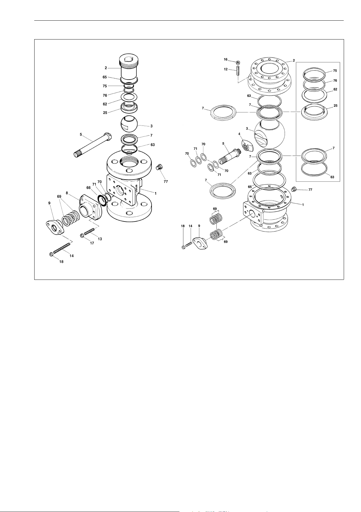
11 DIMENSIONS AND WEIGHTS
11.1 DN 25-40, 65, PN 40
DN 25-40, 65, PN 40
Type Dimensions in mm NPTFU1Kg
DN A A1 ØB ØD K
MA025M 25 160 80 115 25,4 145 1/4 6
MA040M 40 200 87 150 38,1 167 1/4 10,5
MD065M 65 290 95 185 58,7 176 1/2 21
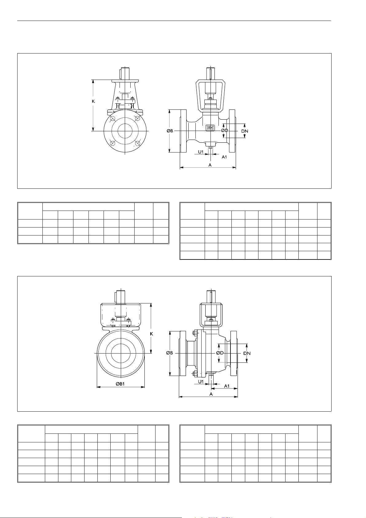
11.2 DN 50-200, PN 10, 16
DN 50-200, PN 25
Type Dimensions in mm NPTFU1Kg
DN A A1 ØB ØB1 ØD K
MA050L 50 216 90 165 146 50,8 168 1/2 16
MA080L 80 282 120 200 203 76,2 229 1/2 34
MA100L 100 305 137 235 254 101,6 264 1/2 62
MA150L 150 403 179 300 367 152,4 342 3/4 146
MA200L 200 502 226 360 467 203,2 440 3/4 264
PN 10, 16
Type Dimensions in mm NPTFU1Kg
DN A A1 ØB ØB1 ØD K
MT050J/K 50 178 79 165 153 50,8 168 1/2 13
MT080J/K 80 203 99 200 194 76,2 189 1/2 23
MT100J/K 100 229 114,5 220 2 52 101,6 250 1/2 42
MT150J/K 150 394 184 285 364 152,4 342 3/4 120
MT200J/K 200 457 229 340 460 203,2 440 3/4 212
PN 40
Type Dimensions in mm NPTFU1Kg
DN A A1 ØB ØB1 ØD K
MA050M 50 216 90 165 146 50,8 168 1/2 16
MA080M 80 282 120 200 203 76,2 229 1/2 34
MA100M 100 305 137 235 254 101,6 264 1/2 62
MA150M 150 403 179 300 367 152,4 342 3/4 14 6
MA200M 200 502 226 375 467 203,2 440 3/4 26 4

11.3 DN 25-40, 65 with hand lever LR
PN 40
Type Dimensions in mm Kg
DN A A1 ØBH J L
MA025M-
LR220
MA040M-
LR220
MD065M-
LR350
25 165,1 80 124 255 193 220 7,5
40 190,5 87 155 293 215 220 12,5
65 290 95 185 320 228 350 25
15
11.4 DN 50-100 with hand lever LR
PN 10, 16
Type Dimensions in mm Kg
DN A A1 ØB ØB1 H J L
MT50J/K-
LR350
MT080J/K-
LR350
MT100J/K-
LR450
50 178 79 165 153 297 220 350 16
80 203 99 200 194 338 241 350 26
100 2 29 114,5 220 2 52 4 28 3 02 4 50 45
PN 25, 40
Type Dimensions in mm Kg
DN A A1 ØB ØB1 H J L
MA050L/M-
LR350
MA080L/M
LR450
MA100L/M-
LR450
50 216 90 165 146 303 220 350 19
-
80 282 120 200 203 383 281 450 37
100 305 137 235 254 443 316 450 65

16
11.5 With hand wheel operator M
G
F
ø Z
V
ØB1
Type Dimensions in mm Kg
FGJ VØZ
M07 196 152 58 39 125 3
M10 297 239 67 52 200 5
M12 357 282 81 67 250 10
M14 435 345 94 90 457 18
M15 532 406 106 123 457 31
M16 642 466 127 154 610 45
K*
J

11.6 DN 25-40, 65 with pneumatic actuator
B1C
17
PN 40
Type Dimensions in mm NPT Kg
DN A A1 ØBF G H I J V X
MA025M-B1C6 25 165,1 80 124 400 260 310 220 203 36 90 1/4 13
MA040M-B1C6 40 190,5 87 155 400 260 350 220 225 36 90 1/4 17
MA040M-B1C9 40 190,5 87 155 455 315 360 215 226 43 110 1/4 22
MD065M-B1C9 65 290 95 185 455 315 382,5 215 235 43 110 1/4 37
MD065M-B1C11 65 290 95 185 540 375 401 225 241 51 135 3/8 43

18
11.7 DN 50-300 with pneumatic actuator B1C
PN 10, 16
Type Dimensions in mm NPT Kg
DN A A1 ØB ØB1 F G H I J V X
MT050J/K - B1C6 50 178 79 165 153 400 260 390 225 226 36 90 1/4 20
MT050J/K - B1C9 50 178 79 165 153 455 315 385 220 227 43 110 1/4 25
MT050J/K - B1C11 50 178 79 165 153 540 375 395 225 233 51 135 3/8 30
MT080J/K - B1C9 80 203 99 200 194 455 315 425 220 248 43 110 1/4 35
MT080J/K - B1C11 80 203 99 200 194 540 375 435 225 254 51 135 3/8 43
MT080J/K - B1C13 80 203 99 200 194 635 445 465 235 270 65 175 3/8 58
MT080J/K - B1C17 80 203 99 200 194 770 495 495 255 285 78 215 1/2 80
MT100J/K - B1C11 100 229 114,5 220 252 540 375 520 225 315 51 135 3/8 62
MT100J/K - B1C13 100 229 114,5 220 252 635 445 555 235 331 65 175 3/8 78
MT100J/K - B1C17 100 229 114,5 220 252 770 545 585 255 346 78 215 1/2 100
MT150J/K - B1C17 150 394 184 285 364 770 545 730 255 438 78 215 1/2 180
MT150J/K - B1C20 150 394 184 285 364 840 575 765 270 457 97 215 1/2 198
MT150J/K - B1C25 150 394 184 285 364 1040 710 825 310 480 121 265 1/2 255
MT150J/K - B1C32 150 394 184 285 364 1330 910 900 350 517 153 395 3/4 370
MT200J/K - B1C20 200 457 229 340 460 840 575 910 270 555 97 215 1/2 290
MT200J/K - B1C25 200 457 229 340 460 1040 710 970 310 578 121 265 1/2 348
MT200J/K - B1C32 200 457 229 340 460 1330 910 1045 350 615 153 395 3/4 470
MT200J/K - B1C40 200 457 229 340 460 1660 1150 1150 370 665 194 505 3/4 660
MT250J/K - B1C25 250 533 267 395/405 548 1040 710 1095 310 658 121 265 1/2 500
MT250J/K - B1C32 250 533 267 395/405 548 1330 910 1170 350 695 153 395 3/4 620
MT250J/K - B1C40 250 533 267 395/405 548 1660 1150 1275 370 745 194 505 3/4 815
MT300J/K - B1C25 300 610 305 445/460 624 1040 710 1175 310 699 121 265 1/2 675
MT300J/K - B1C32 300 610 305 445/460 624 1330 910 1250 350 736 153 395 3/4 795
MT300J/K - B1C40 300 610 305 445/460 624 1660 1150 1350 370 786 194 505 3/4 990
MT300J/K - B1C50 300 610 305 445/460 624 1970 1350 1455 415 836 242 610 1 1380

PN 25
Type Dimensions in mm NPT Kg
DN A A1 ØB ØB1 F G H I J V X
MA050L - B1C6 50 216 90 165 146 400 260 390 225 226 36 90 1/4 22
MA050L - B1C9 50 216 90 165 146 455 315 385 220 227 43 110 1/4 27
MA050L - B1C11 50 216 90 165 146 540 375 475 225 233 51 135 3/8 33
MA080L - B1C9 80 282 120 200 203 455 315 465 220 288 43 110 1/4 46
MA080L - B1C11 80 282 120 200 203 540 375 480 225 295 51 135 3/8 52
MA080L - B1C13 80 282 120 200 203 635 445 510 235 310 65 175 3/8 67
MA080L - B1C17 80 282 120 200 203 770 545 540 255 325 78 215 1/2 90
MA100L - B1C11 100 305 137 235 254 540 375 540 225 329 51 135 3/8 80
MA100L - B1C13 100 305 137 235 254 635 445 560 235 335 65 175 3/8 95
MA100L - B1C17 100 305 137 235 254 770 545 590 255 350 78 215 1/2 120
MA150L - B1C17 150 403 179 300 367 770 545 735 255 440 78 215 1/2 205
MA150L - B1C20 150 403 179 300 367 840 575 770 270 460 97 215 1/2 224
MA150L - B1C25 150 403 179 300 367 1040 710 825 310 480 121 265 1/2 280
MA150L - B1C32 150 403 179 300 367 1330 910 900 350 517 153 395 3/4 400
MA200L - B1C25 200 502 226 360 467 1040 710 975 310 580 121 265 1/2 400
MA200L - B1C32 200 502 226 360 467 1330 910 1050 350 615 153 395 3/4 520
MA250L - B1C25 250 568 285 425 580 1040 710 1110 310 658 121 265 1/2 515
MA250L - B1C32 250 568 285 425 580 1330 910 1185 350 695 153 395 3/4 630
MA250L - B1C40 250 568 285 425 580 1660 1150 1290 370 745 194 505 3/4 825
MA300L - B1C25 300 648 324 485 652 1040 710 1185 310 699 121 265 1/2 660
MA300L - B1C32 300 648 324 485 652 1330 910 1265 350 736 153 395 3/4 780
MA300L - B1C40 300 648 324 485 652 1660 1150 1365 370 786 194 505 3/4 975
MA300L - B1C50 300 648 324 485 652 1970 1350 1470 415 836 242 610 1 1360
19
PN 40
Type Dimensions in mm NPT Kg
DN A A1 ØB ØB1 F G H I J V X
MA050M - B1C6 50 216 90 165 146 400 260 390 225 226 36 90 1/4 22
MA050M - B1C9 50 216 90 165 146 455 315 385 220 227 43 110 1/4 27
MA050M - B1C11 50 216 90 165 146 540 375 475 225 233 51 135 3/8 33
MA080M - B1C9 80 282 120 200 203 455 315 465 220 288 43 110 1/4 46
MA080L - B1C11 80 282 120 200 203 540 375 480 225 295 51 135 3/8 52
MA080L - B1C13 80 282 120 200 203 635 445 510 235 310 65 175 3/8 67
MA080L - B1C17 80 282 120 200 203 770 545 540 255 325 78 215 1/2 90
MA100L - B1C11 100 305 137 235 254 540 375 540 225 329 51 135 3/8 80
MA100L - B1C13 100 305 137 235 254 635 445 560 235 335 65 175 3/8 95
MA100L - B1C17 100 305 137 235 254 770 545 590 255 350 78 215 1/2 120
MA100L - B1C20 100 305 137 235 254 840 575 625 270 370 97 215 1/2 140
MA100L - B1C25 100 305 137 235 254 1040 710 685 310 395 121 265 1/2 200
MA150L - B1C17 150 403 179 300 367 770 545 735 255 440 78 215 1/2 205
MA150L - B1C20 150 403 179 300 367 840 575 770 270 460 97 215 1/2 224
MA150L - B1C25 150 403 179 300 367 1040 710 825 310 480 121 265 1/2 280
MA150L - B1C32 150 403 179 300 367 1330 910 900 350 517 153 395 3/4 400
MA200L - B1C25 200 502 226 375 467 1040 710 975 310 580 121 265 1/2 400
MA200L - B1C32 200 502 226 375 467 1330 910 1050 350 615 153 395 3/4 520
MA250L - B1C25 250 568 285 450 580 1040 710 1110 310 658 121 265 1/2 515
MA250L - B1C32 250 568 285 450 580 1330 910 1185 350 695 153 395 3/4 630
MA250L - B1C40 250 568 285 450 580 1660 1150 1290 370 745 194 505 3/4 825
MA300L - B1C25 300 648 324 515 652 1040 710 1185 310 699 121 265 1/2 660
MA300L - B1C32 300 648 324 515 652 1330 910 1265 350 736 153 395 3/4 780
MA300L - B1C40 300 648 324 515 652 1660 1150 1365 370 786 194 505 3/4 975
MA300L - B1C50 300 648 324 515 652 1970 1350 1470 415 836 242 610 1 1360

20
11.8 DN 25-40, 65 with pneumatic
spring-return actuator B1J
PN 40
Type Dimensions in mm NPT Kg
DN A A1 ØBF G H I J V X
MA025M-B1J8 25 165,1 80 124 560 420 335 220 204 43 135 3/8 24
MA040M-B1J8 40 190,5 87 155 560 420 385 220 225 43 135 3/8 29
MA040M-B1J10 40 190,5 87 155 650 490 400 225 231 51 175 3/8 42
MD065M-B1J10 65 290 95 185 650 490 425 225 241 51 175 3/8 39
MD065M-B1J12 65 290 95 185 800 620 460 235 257 65 215 1/2 66

11.9 DN 50-300 with pneumatic
spring-return actuator B1J
21
PN 10, 16
Type Dimensions in mm NPT Kg
DN A A1 ØB ØB1 F G H I J V X
MT050J/K - B1J8 50 178 79 165 153 560 420 371 220 227 43 135 3/8 31
MT050J/K - B1J10 50 178 79 165 153 650 490 336 225 233 51 175 3/8 44
MT050J/K - B1J12 50 178 79 165 153 800 620 435 235 249 65 215 1/2 72
MT080J/K - B1J10 80 203 120 200 194 650 490 440 225 254 51 175 3/8 55
MT080J/K - B1J12 80 203 120 200 194 800 620 475 235 270 65 215 1/2 82
MT080J/K - B1J16 80 203 120 200 194 990 760 515 255 285 78 265 1/2 125
MT100J/K - B1J12 100 229 137 220 252 800 620 565 235 331 65 215 1/2 102
MT100J/K - B1J16 100 229 137 220 252 990 760 605 255 346 78 265 1/2 145
MT150J/K - B1J16 150 394 179 285 364 990 760 755 255 438 78 265 1/2 235
MT150J/K - B1J20 150 394 179 285 364 1200 935 840 270 457 97 395 3/4 300
MT150J/K - B1J25 150 394 179 285 364 1530 1200 915 310 480 121 505 3/4 475
MT200J/K- B1J20 200 457 226 340 460 1200 935 985 270 555 97 395 3/4 392
MT200J/K- B1J25 200 457 226 340 460 1530 1200 1060 310 578 121 505 3/4 565
MT200J/K - B1J32 200 457 226 340 460 1830 1410 1115 350 615 153 540 1 890
MT250K - B1J25 250 533 267 395 548 1530 1200 1185 310 658 121 505 3/4 720
MT250K - B1J32 250 533 267 395 548 1830 1410 1240 350 695 153 540 1 1050
MT300K - B1J32 300 610 305 445 624 1830 1410 1250 350 736 153 540 1 1225

22
PN 25
Type Dimensions in mm NPT Kg
DN A A1 ØB ØB1 F G H I J V X
MA050L - B1J8 50 216 90 165 146 560 420 375 220 227 43 135 3/8 35
MA050L - B1J10 50 216 90 165 146 650 490 405 225 233 51 175 3/8 48
MA050L - B1J12 50 216 90 165 146 800 620 440 235 249 65 215 1/2 75
MA080L - B1J10 80 282 120 200 203 650 490 485 225 294 51 175 3/8 66
MA080L - B1J12 80 282 120 200 203 800 620 520 235 310 65 215 1/2 93
MA080L - B1J16 80 282 120 200 203 990 760 560 255 325 78 265 1/2 136
MA100L - B1J12 100 305 137 235 254 800 620 570 235 335 65 215 1/2 122
MA100L - B1J16 100 305 137 235 254 990 760 610 255 350 78 265 1/2 165
MA100L - B1J20 100 305 137 235 254 1200 935 695 270 369 97 395 3/4 240
MA150L - B1J16 150 403 179 300 367 990 760 755 255 438 78 265 1/2 250
MA150L - B1J20 150 403 179 300 367 1200 935 840 270 457 97 395 3/4 325
MA150L - B1J25 150 403 179 300 367 1530 1200 915 310 480 121 505 3/4 500
MA150L - B1J32 150 403 179 300 367 1830 1410 970 350 517 153 540 1 820
MA200L- B1J20 200 502 226 360 467 1200 935 985 270 555 97 395 3/4 445
MA200L- B1J25 200 502 226 360 467 1530 1200 1065 310 578 121 505 3/4 620
MA200L - B1J32 200 502 226 360 467 1830 1410 1120 350 615 153 540 1 940
MA250L - B1J25 250 568 285 425 580 1530 1200 1200 310 658 121 505 3/4 730
MA250L - B1J32 250 568 285 425 580 1830 1410 1255 350 695 153 540 1 1050
MA300L - B1J25 300 648 324 485 652 1530 1200 1280 310 699 121 505 3/4 880
MA300L - B1J32 300 648 324 485 652 1830 1410 1335 350 736 153 540 1 1200
PN 40
Type Dimensions in mm NPT Kg
DN A A1 ØB ØB1 F G H I J V X
MA050M - B1J8 50 216 90 165 146 560 420 375 220 227 43 135 3/8 35
MA050M - B1J10 50 216 90 165 146 650 490 405 225 233 51 175 3/8 48
MA050M - B1J12 50 216 90 165 146 800 620 440 235 249 65 215 1/2 75
MA080M - B1J10 80 282 120 200 203 650 490 485 225 294 51 175 3/8 66
MA080M - B1J12 80 282 120 200 203 800 620 520 235 310 65 215 1/2 93
MA080M - B1J16 80 282 120 200 203 990 760 560 255 325 78 265 1/2 136
MA100M - B1J12 100 305 137 235 254 800 620 570 235 335 65 215 1/2 122
MA100M - B1J16 100 305 137 235 254 990 760 610 255 350 78 265 1/2 165
MA100M - B1J20 100 305 137 235 254 1200 935 695 270 369 97 395 3/4 240
MA100M - B1J25 100 305 137 235 254 1530 1200 770 310 392 121 505 3/4 415
MA150M - B1J16 150 403 179 300 367 990 760 755 255 438 78 265 1/2 250
MA150M - B1J20 150 403 179 300 367 1200 935 840 270 457 97 395 3/4 325
MA150M - B1J25 150 403 179 300 367 1530 1200 915 310 480 121 505 3/4 500
MA150M - B1J32 150 403 179 300 367 1830 1410 970 350 517 153 540 1 820
MA200M- B1J20 200 502 226 375 467 1200 935 985 270 555 97 395 3/4 445
MA200M- B1J25 200 502 226 375 467 1530 1200 1065 310 578 121 505 3/4 620
MA200M - B1J32 200 502 226 375 467 1830 1410 1120 350 615 153 540 1 940
MA250M - B1J25 250 568 285 450 580 1530 1200 1200 310 658 121 505 3/4 730
MA250M - B1J32 250 568 285 450 580 1830 1410 1255 350 695 153 540 1 1050
MA300M - B1J25 300 648 324 515 652 1530 1200 1280 310 699 121 505 3/4 880
MA300M - B1J32 300 648 324 515 652 1830 1410 1335 350 736 153 540 1 1200

12 TYPE CODE
23

24
Metso Automation Inc.
Europe, Levytie 6, P.O. Box 310, 00811 Helsinki, Finland. Tel. +358 20 483 150. Fax +358 20 483 151
North America, 44 Bowditch Drive, P.O. Box 8044, Shrewsbury, MA 01545, USA. Tel. +1 508 852 0200. Fax +1 508 852 8172
Latin America, Av. Independéncia, 2500- Iporanga, 18087-101, Sorocaba-São Paulo, Brazil.
Tel. +55 15 3235 9700. Fax +55 15 3235 9748/49
Asia Pacific, 501 Orchard Road, #05-09 Wheelock Place, 238880 Singapore. Tel. +65 673 552 00. Fax +65 673 545 66
Middle East, Roundabout 8, Unit AB-07, P.O. Box 17175, Jebel Ali Freezone, Dubai, United Arab Emirates.
Tel. +971 4 883 6974. Fax +971 4 883 6836
www.metsoautomation.com
en
 Loading...