


Ceramic Ball Valves
Series E2 and E6
Installation, Maintenance and
Operating Instructions
1 E2 70 en • 9/2011

2 1 E2 70 en
Table of Contents
1 GENERAL........................................................ 3
1.1 Valve description.................................... 3
1.2 Valve markings....................................... 3
1.3 Technical data................. ... ....................3
1.4 CE marking ............................................ 3
1.5 Recycling and disposal ...... ... .................3
1.6 Safety precautions ................................. 4
2 TRANSPORTATION, RECEPTION AND
STORAGE........................................................ 4
3 INSTALLATION AND USE .............................. 4
3.1 Valve insulation......................................6
4 MAINTENANCE............................................... 6
4.1 General ..................................................6
4.2 Changing the gland packing,
A-construction ........................................6
4.3 Changing the gland packing,
H-construction........................................8
4.4 Changing the gasket of the gland packing... 8
4.5 Changing the bearing,
A-construction and H-construction.........8
4.6 Changing the ceramic parts ................... 8
4.7 Detaching and installing the actuator..... 9
5 MALFUNCTION ............................................. 10
6 TOOLS NEEDED ........................................... 10
7 ORDERING SPARE PARTS ......................... 10
8 EXPLODED VIEWS AND PARTS LIST ........ 11
9 DIMENSIONS AND WEIGHTS ...................... 12
10 TYPE CODE................................................... 15
READ THESE INSTRUCTIONS FIRST!
These instructions provide information needed for safe handling and operation of the valve.
If you require additional assistance, please contact the manufacturer or manufacturer’s representa tive.
Addresses and phone numbers are printed on the back cover.
SAVE THESE INSTRUCTIONS!
Subject to change without notice.
All trademarks are property of their respective owners.

1 E2 70 en 3
1 GENERAL
1.1 Valve description
The E2 ceramic ball valve is a flangeless (wafer type),
and E6 is a single flange (lug type) reduced-bore valve
specially designed for control of erosive media.
The body and shaft are metal, while the trim is ceramic.
There are no separate ball seats; instead, the seating
surfaces are directly ground into the ceramic bushings.
The insert retaining ceramic parts is attached to the
body with threaded joint. The flow medium comes into
contact with the metallic valve body. Note this when the
valve is used for aggressive media.
Rotation transmission between shaft and ball takes
place through a slot head. Axial bearings are located
outside the valve, under the actuator mounting piece.
The valve is usually equipped with an actuator. (For
details, see type-specific instructions.
1.2 Valve markings
The markings stamped on the body indicate the
❑ body material
❑ nominal size
❑ pressure rating
The valve also has an identification plate, the type of
which depends upon the size of the valve. See Figure 1.
1.3 Technical data
Face-to-face length: IEC 534-3-2 / ISA S75.04
Body pressure rating: ASME Class 300
Max. diff. pressure/ temperature:
in control applications
ASME Class 150
in shut-off applications
ASME Class 300,
see Figure 2
For NPS 8/DN 200 the maximum
differential pressure is limited
to 20 bar.
Max. oper. temp.: A-construction: +200 °C (+392 °F)
H-construction: +450 °C (+842 °F)
Direction of flow: insert on upstream side
Characteristic curve: equal percentage
Tightness class: 10 x ISO 5208 Rate D
Media: not for inflammable media
Dimensions: see Section 9
Weights: see Section 9
Temperature °F
900 1000
110 0
100 200 300 400 500 600 700 800
bar
100
80
60
50
40
30
20
10
8
6
5
4
3
2
CF8M Class 150
CF8M Class 300
1200
1300
1400
psi
1500
1200
900
700
600
500
300
150
120
90
70
60
50
30
Fig. 1 Alternatives for identification plate
The different sections of the identification plate give the
following informations:
1. body material
2. trim material
3. shaft material
4. seat material
5. highest operating temperature
6. lowest operating temperature
7. maximum shut-off pressure differential
8. type designation
9. number in manufacturer’s list
10. pressure class
The type designation is defined in the type code, see
Section 10.
1.0
100 200 300 400 500 600 700 800
0
Temperature °C
Fig. 2 Pressure-temperature diagram
1.4 CE marking
The valve meets the requirements of the European
Directive 97/23/EC relating to pressure equipment, and
has been marked according to the Directive.
1.5 Recycling and disposal
Most valve parts can be recycled if sorted according to
material. Most parts have material marking. A material
list is supplied with the valve. In addition, separate
recycling and disposal instructions are available from
the manufacturer. A valve can also be returned to the
manufacturer for recycling and disposal against a fee.

4 1 E2 70 en
1.6 Safety precautions
CAUTION:
Due to the nature of ceramic material used in valve internals, the valve might cause an ignition of explosive gas
mixtures. Valve internals, when operating against each
other may cause sufficient heat to ignite the gaseous mixture inside the valve. Therefore the safe use of the valve
must be assessed when used in potentially explosive and
flammable applications. According to the Hazard Analysis
the valve is not creating an ignition risk to its environment
outside the valve. For further information, please contact
Metso’s Automation business.
CAUTION:
Do not exceed the valve performance limitations!
Exceeding the limitations marked on the valve body may
cause damage and lead to uncontrolled pressure
release.
Damage or personal injury may result.
CAUTION:
Do not dismantle the valve or remove it from the
pipeline if the valve is pressurized!
Damage or personal injury may result. Dismantling a
pressurized valve will cause uncontrolled pressure
release. Always isolate the required part of the pipeline,
release the pressure from the valve and remove the
medium before dismantling the valve. Be aware of the
medium type. Protect people and equipment in the area
from any harmful or poisonous medium. If the valve is
actuator operated, close and detach the actuator pressure supply pipeline.
CAUTION:
Be aware of the ball cutting movement!
When the valve is actuated, the ball functions as a cutting device.
Do not stick your hand or other body parts into the open
flow port. Prevent foreign objects from being left inside
the pipeline. If the valve is actuator operated, close and
detach the actuator pressure supply pipeline.
CAUTION:
Be aware of noise emission!
Depending on the application the valve may cause noise
emission during use. The noise level can be measured
with equipment designed for this purpose or by using
the Metso Nelprof software. Pay attention to work environment legislation concerning noise emission.
CAUTION:
Be aware of extreme temperatures!
During use the valve body may be very cold or very
hot. If extreme temperatures occur, protect people
from frost injuries or burns.
NOTE:
Do not drop, knock or hit the valve!
Internal parts of the valve are made of ceramic material.
Although the material is robust, it will not tolerate impact
as metals do.
NOTE:
Media which may solidify should not be allowed to stand
in the ball valve. Wash such media from the valve using a
suitable arrangement. Cycle a valve few times when
washing.
2 TRANSPORTATION, RECEPTION
AND STORAGE
Valves are delivered in the usual Metso packaging,
unless otherwise agreed with the customer.
Make sure that the valve and any possible accessories
have not been damaged during transport.
Do not remove the bore protectors before installation.
Store the valve with care, preferably indoors and in a
dry environment.
Take the valve to the installation site only just before
installation.
Fig. 3 Storage of the valve
NOTE:
Ceramic valves must be handled with particular care.
3 INSTALLATION AND USE
Remove the bore protectors and check that the valve is
clean. Also ensure that the pipeline is clean.
The pipeline must be firmly supported so that the valve
is not subjected to additional strain.
The valves can be installed between the following
flanges:
❑ EN PN 10, 16, 25, 40
❑ ASME 150, 300
❑ ISO 7005 PN 20, PN 50
❑ JIS 10 K, 16 K, 20 K, 30 K
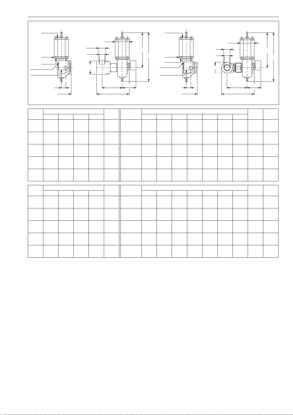
In some valve sizes the body of the valve has thread fillets for the two flange screws located closest to the shaft.
Size NPS 8 / DN 200 has thread fillets for all flange
screws. See Figure 4 and Tables 1 to 3. All other dimensions are shown in Section 9.
The valve is tight in both directions and may be
installed in any position. It must not, however, be
installed in such a way that the actuator is below the
valve (see Figure 5).
The actuator must not come into contact with the pipeline, as vibrations in the pipeline might damage the
actuator and its performance.

1 E2 70 en 5
S
R
Lmin.
A
S
Lmin.
R
TYPE E2
S
R
Lmin.
S
R
Lmin.
A
TYPE E6
Fig. 4 Flange drilling / neck bolting
Table 1 Flange drilling / neck bolting, dimensions in mm. ASME 150 / ISO 7005 PN 20. ASME 300 / ISO 7005 PN 50
ASME 150 / ISO 7005 PN 20 ASME 300 / ISO 7005 PN 50
TYPE
E2_025/E2_01 102 4 - - - - 4 - - - -
E2_040/E2_1H 114 4 - - - - 4 - - - -
E2_050/E2_02 124 4 - - - - 8 2 5/8" UNC / M16 17.0 70
E2_080/E2_03 165 4 - - - - 8 2 3/4" UNC / M20 20.0 85
E2_100/E2_04 194 8 2 5/8" UNC / M16 17.0 75 8 2 3/4" UNC / M20 20.0 90
E6_025/E6_01 102 4 - 1/2" UNC / M12 - - 4 - 5/8" UNC / M16 - -
E6_040/E6_1H 114 4 - 1/2" UNC / M12 - - 4 - 3/4" UNC / M20 - -
E6_050/E6_02 124 4 - 5/8" UNC / M16 - - 8 2 5/8" UNC / M16 28.5 75
E6_080/E6_03 165 4 - 5/8" UNC / M16 - - 8 2 3/4" UNC / M20 28.5 85
E6_100/E6_04 194 8 2 5/8" UNC / M16 29.5 80 8 2 3/4" UNC / M20 29.5 90
E6_150/E6_06 229 8 2 3/4" UNC / M20 28.5 80 12 2 3/4" UNC / M20 28.5 95
E6_200/E6_08 243 8 8 3/4" UNC / M20 28.5 80 12 12 7/8" UNC / M24 28.5 95
*) total number / flange
**) number of neck bolts / flange
Face-to-face A
Number of flange bolts *)
Number of neck bolts **)
Bolt size R
Depth of neck bolt drilling S
Length of neck bolts Lmin
Number of flange bolts *)
Number of neck bolts **)
Bolt size R
Depth of neck bolt drilling S
Length of neck bolts Lmin
Table 2 Flange drilling / neck bolting, dimensions in mm. EN PN 10, 16, 25, 40
EN PN 10 EN PN 16 EN PN 25 EN PN 40
TYPE
E2_025/E2_01 102 4 - - - - 4 - - - - 4 - - - - 4 ----
E2_040/E2_1H 114 4 - - - - 4 - - - - 4 - - - - 4 ----
E2_050/E2_021244----4----4----4----
E2_080/E2_03 165 8 2 M16 17.0 65 8 2 M16 17.0 65 8 2 M16 17.0 70 8 2 M16 17.0 70
E2_100/E2_04 194 8 2 M16 17.0 65 8 2 M16 17.0 65 8 2 M20 20.0 75 8 2 M20 20.0 75
E6_025/E6_01 102 4 - M12 - - 4 - M12 - - 4 - M12 - - 4 - M12 - -
E6_040/E6_1H 114 4 - M16 - - 4 - M16 - - 4 - M16 - - 4 - M16 - -
E6_050/E6_02 124 4 - M16 - - 4 - M16 - - 4 - M16 - - 4 - M16 - -
E6_080/E6_03 165 8 2 M16 28.5 70 8 2 M16 28.5 70 8 2 M16 28.5 75 8 2 M16 28.5 75
E6_100/E6_04 194 8 2 M16 29.5 70 8 2 M16 29.5 70 8 2 M20 29.5 80 8 2 M20 29.5 80
E6_150/E6_06 229 8 2 M20 28.5 75 8 2 M20 28.5 75 8 2 M24 28.5 85 8 2 M24 28.5 85
E6_200/E6_08 243 8 8 M20 28.5 75 12 12 M20 28.5 75 12 12 M24 28.5 85 12 12 M27 28.5 85
*) total number / flange
**) number of neck bolts / flange
Face-to-face A
Number of flange bolts *)
Number of neck bolts **)
Bolt size R
Depth of neck bolt drilling S
Length of neck bolts Lmin
Number of flange bolts *)
Number of neck bolts **)
Bolt size R
Depth of neck bolt drilling S
Length of neck bolts Lmin
Number of flange bolts *)
Number of neck bolts **)
Bolt size R
Depth of neck bolt drilling S
Length of neck bolts Lmin
Number of flange bolts *)
Number of neck bolts **)
Bolt size R
Depth of neck bolt drilling S
Length of neck bolts Lmin

6 1 E2 70 en
Table 3 Flange drilling / neck bolting, dimensions in mm. JIS 16 K, 20 K, 30 K
JIS 10 K JIS 16 K - 20 K JIS 30 K
TYPE
E2_025/E2_011024----4----4- --
E2_040/E2_1H 114 4 - - - - 4 - - - - 4 - - - -
E2_050/E2_02 124 4 - - - - 8 2 M16 17.0 65 8 2 M16 17.0 70
E2_080/E2_03 165 8 2 M16 17.0 65 8 2 M20 20.0 75 8 2 M20 20.0 80
E2_100/E2_04 194 8 2 M16 17.0 65 8 2 M20 20.0 75 8 2 M22 22.0 90
E6_025/E6_01 102 4 - M16 - - 4 - M16 - - 4 - M16 - -
E6_040/E6_1H 114 4 - M16 - - 4 - M16 - - 4 - M20 - -
E6_050/E6_02 124 4 - M16 - - 8 2 M16 28.5 70 8 2 M16 28.5 70
E6_080/E6_03 165 8 2 M16 28.5 70 8 2 M20 28.5 75 8 2 M20 28.5 80
E6_100/E6_04 194 8 2 M16 29.5 70 8 2 M20 29.5 80 8 2 M22 29.5 90
E6_150/E6_06 229 8 2 M20 28.5 75 12 2 M22 28.5 85 12 2 M24 28.5 95
E6_200/E6_08 243 12 12 M20 28.5 75 12 12 M22 28.5 85 12 12 M24 28.5 95
*) total number / flange
**) number of neck bolts / flange
Face-to-face A
Number of flange bolts *)
Number of neck bolts **)
Bolt size R
Depth of neck bolt drilling S
Length of neck bolts Lmin
Number of flange bolts *)
Number of neck bolts **)
Bolt size R
Depth of neck bolt drilling S
Length of neck bolts Lmin
Number of flange bolts *)
Number of neck bolts **)
Bolt size R
Depth of neck bolt drilling S
Length of neck bolts Lmin
3.1 Valve insulation
If necessary, the valve may be insulated. Insulation
must not continue above the upper level of the valve
body, see Figure 6.
Insulation limit
Fig. 5 Avoid this mounting position
To facilitate easy maintenance, the actuator should be
installed in such a way that there is plenty of room for
removing it.
The screws, nuts and washers used should be equivalent to the fastenings used elsewhere in the pipeline.
Pay particular attention when centring the flange gasket.
The inside diameter of the gasket should be acc. to the
nominal size of the valve, i.e. the gasket covers the insert (6)
and the rim of the ceramic bushing (3).
NOTE:
An eccentric flange gasket may cause premature body
wear, par ticularly with media containing particles.
The pipeline should be flushed carefully before use.
The valve should be kept entirely open during flushing.
Fig. 6 Insulation of the valve
4 MAINTENANCE
CAUTION:
Observe the safety precautions mentioned in 1.6
before you start work!
4.1 General
The valve does not require regular maintenance. Its operation should, however, be checked at regular intervals.
The end use may carry out the following maintenance
tasks himself.
4.2 Changing the gland packing,
A-construction
The component numbers given in brackets refer to the
diagram and component list given in Section 8.1. See
also Figure 7.

1 E2 70 en 7
4.2.1 Disassembly
CAUTION:
Do not detach or disassemble a pressurized valve!
This warning also applies to individual components (13).
1. Detach the air supply conduit from the actuator. Also
detach any cables preventing the removal of the actuator.
2. Remove the actuator from the bracket (5) by
unscrewing the fixing screws. Pull the actuator from
the shaft (4). Detaching the actuator is described in
more detail in Section 4.7.1.
3. Detach the key (20) from the shaft.
4. Detach the bracket (5) from the body (1) by opening
the screws (13) M12 or M16.
5. Detach the bearing (8), the axial bearing (7) and the
lock ring (19).
6. Loosen the strain ring (9) with a special tool, see
Table 4.
7. Pull the shaft (4), and lift it and gland bushing (10)
and parts (11, 12, 17) out of the valve body.
8. Pull the gland bushing off the shaft while rotating.
Now the gland packing may be disassembled.
9. Remove the gasket (16) between the gland bushing
and the body from the valve body.
4.2.2 Replacing parts
The gland packing set includes the V-ring set (11) and
the spring (12). Replace both parts at the same time.
NOTE:
Replace the gasket (16) between the gland bushing (10)
and the body (1) whenever the strain ring has been loosened. Leakage of the V-ring set (11) and leakage of the
gasket (16) may cause similar symptoms.
The O-ring (17) should be replaced if it is damaged.
The main purpose of the O-ring is to protect the shaft
from erosive media, such as sludge, and it therefore
does not need to be changed regularly.
4.2.3 Assembly
1. Apply silicon grease to the O-ring (17) and install it
into the gland bushing (10) cavity.
NOTE:
Make sure you do not damage the O-ring with the shaft
keyway and the shaft shoulder.
2. Slip the gland bushing (10) onto the shaft (4).
3. Install the spring (12) into the bottom of the gland
bushing (10). Before installation, the spiral should
be completely compressed once, for example in a
vice. This will make installation of the strain ring easier, since the working height of the spiral is roughly
0.6 x the free height of the spring.
4. Once the spiral is in place, slip the sheet ring (15)
into position. After this, install the V-ring (11) onto the
shaft, one by one.
NOTE:
Make sure you do not damage the gland packing rings
with the shaft keyway or shaft shoulder.
The order from bottom to top of the different rings is as
follows:
❑ base ring
❑ angle rings
❑ saddle ring
5. Place the gasket (16) into the valve body.
6. Insert the shaft together with the gland bushing
back into the valve body.
7. The shaft joint on the ball has been shaped in such
a way that the shaft only fits seat when it is in the
correct position. Check the direction of the bore by
observing the indicator line at the top of the shaft,
and take the position of the keyway into account
when you install the actuator.
8. Lubricate the thread of the strain ring with, for example, Molykote. Then fasten the strain ring (9). When
correctly fastened, the ring shoulder must be at least
on a level with the body, or 0.1 mm below it. The tightening torques are given in Table 4. The shoulder of the
strain ring must not remain above the surface level of
the body.
Table 4 Tightening torques of strain ring
Nominal
size
DN
25/20 M39 x 1.5 190 34-36 F14096_01
40/32 M45 x 1.5 250 40-42 F14096_1H
50/40 M50 x 2 320 45-50 F14096_02
80/65 M64 x 2 340 58-62 F14096_03
100/80 M75 x 2 560 68-75 F14096_04
150/100 M95 x 2 1330 80-90 F14096_06
200 M95 x 2 1330 80-90 F14096_06
Thread
Torque
Nm
Tool
DIN 1810A
Special
tool
9. Make sure that the bracket (5) is not carrying the
weight of the valve because this would have an
immediate effect on the bearing clearance.
10.Install the lock ring (19), the axial bearing (7) and
the bearing (8) onto the shaft.
11.Attach the bracket to the valve body. While fastening
the screws, make sure that the hole in the bracket is
properly centered in relation to the shaft. For the
correct tightening torques, see Table 5.
12.Install the actuator. See Section 4.7.2.
0...0,1 mm bellow the
top level of the bracket
sheet ring
(15)
spring
(12)
gland
bushing
(10)
gasket (16)shaft (4)
bracket (5)
strain ring
(9)
saddle ring
(11)
angle ring
(11)
base rings
(11)
O-ring
(17)
Fig. 7 Sealing of the shaft, A-construction

8 1 E2 70 en
Table 5 Tightening torques of bracket screws
Nominal size
DN
25/20, 40/32, 50/40 M12 80 19
80/65, 100/80, 150/100, 200 M16 190 24
Thread
Torque
Nm
Tool size
4.3 Changing the gland packing,
H-construction
CAUTION:
Do not detach or disassemble a pressurized valve!
This warning also applies to individual components (13).
The part numbers in this section refer to the diagram
and part list in Section 8.2 .
1. Unfasten the nuts (24) of the gland (22) and lift up
the gland.
2. Remove the old packing rings (11) by using, for
example, a sharp pricker.
3. Install the new packing rings.
4. Place the nuts on the studs and tighten the gland
packings while the valve is not pressurized, see
Table 6.
5. Retighten if necessary.
Table 6 Tightening torques of gland nuts
Nominal size
DN
25 M12 40 19
40 M12 50 19
50 M12 80 19
80 M16 55 24
100 M16 90 24
150, 200 M16 105 24
Thread
Torque
Nm
Tool size
4.4 Changing the gasket of the gland
packing
In an H-construction valve, changing the gland packing
does not require unfastening the strain ring, and this
does not entail changing the gasket (16).
When the gasket (16) needs to be changed, this can be done
by following the same instructions that were given for the Aconstruction. Note that there is no O-ring in the H-construction.
4.5 Changing the bearing,
A-construction and H-construction
1. Detach the actuator from the bracket, see Section
4.7.1.
2. Detach the bracket (5) from the valve body (1) by
unscrewing fixing screws (13) M12 or M16 and
detach the key from the shaft.
3. Detach and change the bearing (8).
4. Attach the bracket to the valve, see Table 5.
5. Install the actuator, see Section 4.7.2.
4.6 Changing the ceramic parts
Changing the ceramic parts, ball (2) and bushings (3)
requires special tools. It is highly recommended that
this work is done by the Metso service organisation.
4.6.1 Disassembly
1. Detach the actuator from the valve, see Section
4.7.1.
2. Detach the key (20), fixing screws (13), bracket (5),
axial bearing (7), bearing (8) and lock ring (19).
3. Fasten the valve firmly into a vice the insert (6) pointing upwards.
4. Fasten the special tool, Table 7, to the insert and
turn it open without removing it.
5. Remove the strain ring (9) with a special tool,
Table 4. See also Sections 4.2.1, 4.3 and 4.4.
6. Pull the shaft (4) with gland bushing (10) out of the
body.
7. Remove the insert (6) and detach the ceramic parts,
bushing (3), ball (2) and bushing (3), from the body.
8. Remove the gasket (25) between the insert and
body (8"/DN 200 only).
NOTE:
Replace the gasket (25) between the insert (6) and the
body (1) whenever the insert has been loosened.
4.6.2 Assembly
1. Apply Molykote 312R lubricant to the threads of the
insert (6).
2. Turn the insert into metal-to-metal contact with the
body (without ceramic parts) and draw a mark with
a felt tip pen to the body and insert seam.
3. Remove the insert.
4. Install the sheet rings (14) on the bushings (3).
5. Place the ball (2) between the bushings (3).
6. Push the ceramic parts as a package into the body.
Please note the position of the shaft slot.
7. Install the gasket (25) on the body (1) (8"/DN 200 only).
8. Turn the insert (6) lightly into the body.
9. Push a assembly guide tool, Table 7, through the
gland bore into the slot of the ball. Make sure that
the tool is properly engaged with the ball. The tool
will keep the bushings (3) in place during the tightening of the insert (6).
Table 7 Assembly guide tool
Nominal size Tool
1" / DN 25 280139
1.5" / DN 40 280140
2" / DN 50 280141
3" / DN 80 280142
4" / DN 100 280143
6" / DN 150 280529
8" / DN 200 F33977
10.Fasten the valve firmly into a vice the insert (6) pointing
upwards and tighten the insert evenly using a special
tool 1...2 mm past the mark made earlier. See Table 8.

1 E2 70 en 9
Table 8 Tightening torques of insert
Nominal size
DN
25/20 M52 x 1,5 60 C279922
40/32 M70 x 2 120 C279921
50/40 M85 x 2 240 C279921
80/65 M115 x 2 440 C279920
100/80 M140 x 2 770 C279920
150/100 M200 x 3 1450 F05016
200 M250 x 3 2000 F33976
*) Graphite lubricant applied to the threads
Thread
Max. torque
Nm *
Tool
11.Remove the assembly guide tool from the gland
bore and mount the shaft (4). See Sections 4.2.3,
4.3 and 4.4 for details of gland packing assembly.
Tighten the strain ring (9) according to Table 4.
4.7 Detaching and installing the actuator
4.7.1 Detaching from the valve
1. Detach the air supply tube from the actuator. Also detach
any cables preventing the removal of the actuator.
2. Detach the actuator from the bracket (5) by
unscrewing the fixing screws.
3. Pull the actuator off the shaft by using a special extraction tool, Figure 8. Prevent the shaft from pressing the
ceramic ball when removing, e.g. by gripping the shaft
with self-locking pliers (don’t damage the shaft) .
NOTE:
Make a note of the mutual position of the valve and the
actuator. This will enable you to keep the operating direction unchanged during reassembly. Also make a note of
the position of the actuator (valve open/closed).
4.7.2 Installation onto the valve
Clean the shaft boring of the actuator. Lubricate the
shaft boring and the valve shaft with, for example,
Cortec® VCI 369 anticorrosive agent.
The installation position of the actuator is determined as
follows:
❑ The B1C-actuator is installed in such a way that
the piston is in the extreme outward position
when the valve is closed.
❑ The B1J/B1JA-actuator is installed in one of two
positions, depending on the function required
(spring opens/spring closes).
❑ The actuator mounted the valve before is
installed in the same position.
❑ Carefully insert the actuator over the valve shaft
and make sure the shaft does not press the
ceramic ball, use e.g. self-locking pliers (don’t
damage the shaft).
NOTE:
Do not strike at the actuator during installation because
this might damage the ceramic parts.
❑ Make sure that the actuator is straight in relation
to the valve.
❑ Insert and tighten the fixing screws.
❑ Check to see that the limiter screws of the open
and closed position are properly adjusted.
NOTE:
The actuator has an arrow indicating the flow direction.
Make sure that this arrow is in the correct position in relation
to the bore.
NOTE:
The position of the ball is indicated by means of a groove at
the top of the shaft, which shows the direction of the bore.
Fig. 8 Removal of the actuator with an extractor
More information concerning the actuator is available in
the installation, operation and maintenance instructions
given for the model in question.

10 1 E2 70 en
5 MALFUNCTION
Table 9 shows malfunctions that might appear after prolonged use.
Table 9 Malfunctions
Symptom Possible fault Recommended action
Valve can not be opened/closed Impurities on the ball surface Clean the ball surface mechanically
through the flow ports
Leakage at the base of the shaft Gland packing leaks Check tightening of the strain ring/gland.
Change the gland packing, if needed
Gasket (16) leaks Check tightening of the strain ring.
Change the gasket, if needed
Valve is not tight Excessive wearing Contact manufacturer
Shaft presses ceramic parts Pull the shaft up
6 TOOLS NEEDED
In addition to the usual standard tools, the following
special tools are needed:
❑ Unfastening/tightening the strain ring:
- special tool, see Table 4
❑ Removing the actuator:
- extraction tool 303821 (BC 6)
- extraction tool H797 (BC/BJ 8-10)
- extraction tool H798 (BC/BJ 12-16)
❑ Unfastening/tightening the insert:
- special tool, see Table 7
❑ Assembling the ceramic parts:
- assembly guide, see Table 8
The special tools are available from the manufacturer.
7 ORDERING SPARE PARTS
When ordering spare parts, always include the following information:
❑ type code, sales order number, serial number
(stamped on a valve body)
❑ number of the parts list, part number, name of
the part and quantity required
This information can be found from the identification
plate or documents.

1 E2 70 en 11
8 EXPLODED VIEWS AND PARTS LIST
A-construction H-construction
Item Qty Description Spare part category
11Body
21Ball 3
3 2 Bushing 2
41Shaft 3
51Bracket
6 1 Insert
7 1 Axial bearing 3
81Bearing 1
9 1 Strain ring
10 1 Gland bushing
11 1 V-ring set 1
12 1 Spring (A-construction only)
13 4 Hexagon screw
14 2 Sheet ring 1
15 1 Sheet ring (A-construction only) 3
16 2 Gasket 1
17 1 O-ring (A-construction only) 1
19 1 Lock ring
20 1 Key
21 1 Identification plate
22 1 Gland (H-construction only)
23 2 Stud (H-construction only)
24 2 Hexagon nut (H-construction only)
25 1 Plate ring (8" / DN 200 only) 1
Spare part category 1: Recommended soft parts, always needed for the repair. Delivered as a set.
Spare part category 2: Parts for replacing of the seat. Delivered as a set.
Spare part category 3: Parts for replacing of the closing element.
Spares for the full overhaul: All parts from the categories 1, 2 and 3.

12 1 E2 70 en
9 DIMENSIONS AND WEIGHTS
Dimensions of
mounting level acc. to
ISO 5211
DN
P
O
øD
A
E2 DN25-100
Valve is in open position
Key acc. to ANSI B17.1
mounting level acc. to
M
R
( L )
øB
Dimensions of
ISO 5211
E
DN
øD
P
O
A
E6 DN25-200
Valve is in open position
Key acc. to ANSI B17.1
M
R
( L )
øB
E
Dimensions, mm
DN A
E2 E6
ø B ø B E2 E6
Eø DL O P R M
Mounting
face
Weight, kg
25 102 63.5 130 181 20 8 15 16.9 25 4.76 F07 5 7
40 114 82 160 186 32 8 20 22 35 4.76 F07 7 11
50 124 100 165 202 40 8 25 27.7 46 6.35 F07/F10 10 14
80 165 132 210 256 65 10 35 39 58 9.53 F12 19 27
100 194 157 254 282 80 10 40 44.5 68 9.53 F12/F14 30 45
150 229 - 325 363 100 12 55 60.5 90 12.7 F14 - 105
200 243 - 380 391 135 12 55 60.5 90 12.7 F16 - 330
Dimensions, inch
NPS A
E2 E6
Ø B Ø B E2 E6
EØ DL O P R M
Mounting
face
Weight, lb
1 4.02 2.50 5.12 7.13 0.79 0.31 0.59 0.67 0.98 3/16 F07 11 15
1 1/2 4.49 3.23 6.30 7.32 1.26 0.31 0.79 0.87 1.38 3/16 F07 15 24
2 4.88 3.94 6.50 7.95 1.57 0.31 0.98 1.09 1.81 1/4 F07/F10 22 31
3 6.50 5.20 8.27 10.08 2.56 0.39 1.38 1.54 2.28 3/8 F12 42 60
4 7.64 6.18 10.00 11.10 3.15 0.39 1.57 1.75 2.68 3/8 F12/F14 66 99
6 9.02 - 12.80 14.29 3.94 0.47 2.17 2.38 3.54 1/2 F14 - 231
8 9.57 - 14.96 15.39 5.31 0.47 2.17 2.38 3.54 1/2 F16 - 728
1 E2 70 en 13
I
NPT *) **)
NPT *)
NPT ***)
SUPPLY 1/4 NPT
SIGNAL PG 11
Valve
type
V
DN ø D A ø B F G H I J V X
MOUNTING POSITION A (STANDARD)
ØB
Dimensions, mm
X
DN
ØD
A
WeightkgActuator
E2 025 25 20 102 64 5
E2 040 40 32 114 82 7
E2 050 50 40 124 100 10
E2 080 80 65 165 132 19
E2 100 100 80 194 157 30
H
IJ
type
B1C 6/15
B1J 8/15
B1JA 8/15
B1C 6/20
B1J 8/20
B1JA 8/20
B1C 9/25
B1J 10/25
B1JA 8/25
B1C 13/35
B1J 12/35
B1JA 12/35
B1C 13/40
B1J 16/40
B1JA 16/40
NPT *) **)
G
F
NPT *)
NPT ***)
SUPPLY 1/4 NPT
SIGNAL PG 11
V
A
Dimensions, mm
400
560
560
400
560
560
455
650
560
635
800
800
635
990
990
260
420
420
260
420
420
315
490
420
445
620
620
445
760
760
290
314
314
295
319
319
320
359
333
432
452
452
461
521
521
220
215
215
220
215
215
215
220
215
230
235
235
230
250
250
MOUNTING POSITION B
DN
ØD
ØB
213
214
214
209
210
210
215
221
215
279
279
279
295
310
310
36
43
43
36
43
43
43
51
43
65
65
65
65
78
78
X
G
F
J
H
Weight
90
135
135
90
135
135
110
175
135
175
215
215
175
265
265
NPT
1/4*
3/8**
3/8***
1/4*
3/8**
3/8***
1/4*
3/8**
3/8***
3/8*
1/2**
1/2***
3/8*
1/2**
1/2***
kg
22
22
11
24
24
20
40
27
50
76
76
61
130
130
9
Valve
type
E2 0 1 0.79 4.02 2.52 11
E2 1H 1 1/2 1.26 4.49 3.23 15
E2 02 2 1.57 4.88 3.94 22
E2 03 3 2.56 6.50 5.20 42
E2 04 4 3.15 7.64 6.18 66
Dimensions, inch
WeightlbActuator
Size ø D A ø B F G H I J V X
B1C 6/15
B1J 8/15
B1JA 8/15
B1C 6/20
B1J 8/20
B1JA 8/20
B1C 9/25
B1J 10/25
B1JA 8/25
B1C 13/35
B1J 12/35
B1JA 12/35
B1C 13/40
B1J 16/40
B1JA 16/40
See Tables 1 to 3 for flange bolting dimensions
type
15.75
22.05
22.05
15.75
22.05
22.05
17.91
25.59
22.05
25.00
31.50
31.50
25.00
38.98
38.98
10.24
16.54
16.54
10.24
16.54
16.54
12.40
19.29
16.54
17.52
24.41
24.41
17.52
29.92
29.92
Dimensions, inch
11.42
12.36
12.36
11.61
12.56
12.56
12.60
14.13
13.11
17.01
17.80
17.80
18.15
20.51
20.51
8.66
8.46
8.46
8.66
8.46
8.46
8.46
8.66
8.46
9.06
9.25
9.25
9.06
9.84
9.84
8.39
8.43
8.43
8.23
8.27
8.27
8.46
8.70
8.46
10.98
10.98
10.98
11.61
12.20
12.20
1.42
1.69
1.69
1.42
1.69
1.69
1.69
2.01
1.69
2.56
2.56
2.56
2.56
3.07
3.07
3.54
5.31
5.31
3.54
5.31
5.31
4.33
6.89
5.31
6.89
8.46
8.46
6.89
10.43
10.43
NPT
1/4*
3/8**
3/8***
1/4*
3/8**
3/8***
1/4*
3/8**
3/8***
3/8*
1/2**
1/2***
3/8*
1/2**
1/2***
Weight
lb
20
48
48
24
53
53
44
88
59
110
167
167
134
286
286

14 1 E2 70 en
MOUNTING POSITION A (STANDARD)
ØB
Dimensions, mm
DN
X
ØD
A
WeightkgActuator
SUPPLY 1/4 NPT
SIGNAL PG 11
Val ve
type
NPT *) **)
NPT *)
NPT ***)
V
DN ø D A ø B F G H I J V X
E6 025 25 20 102 130 7
E6 040 40 32 114 160 11
E6 050 50 40 124 165 14
E6 080 80 65 165 210 27
E6 100 100 80 194 254 45
E6 150 150 100 229 325 105
E6 200 200 135 243 380 330
H
IJ
type
B1C 6/15
B1J 8/15
B1JA 8/15
B1C 6/20
B1J 8/20
B1JA 8/20
B1C 9/25
B1J 10/25
B1JA 8/25
B1C 13/35
B1J 12/35
B1JA 12/35
B1C 13/40
B1J 16/40
B1JA 16/40
B1C 20/55
B1J 20/55
B1JA 20/55
B1C 25/55
B1J 25/55
B1JA 25/55
NPT *) **)
G
F
NPT *)
NPT ***)
SUPPLY 1/4 NPT
SIGNAL PG 11
V
A
Dimensions, mm
400
560
560
400
560
560
455
650
560
635
800
800
635
990
990
840
1200
1200
1075
1490
1490
260
420
420
260
420
420
315
490
420
445
620
620
445
760
760
575
935
935
725
1140
1140
323
347
347
334
358
358
353
391
365
472
492
492
510
570
570
658
748
748
762
882
882
220
215
215
220
215
215
215
220
215
230
235
235
230
250
250
270
270
270
327
327
327
MOUNTING POSITION
DN
ØD
ØB
213
214
214
209
210
210
215
221
215
279
279
279
295
310
310
388
388
388
439
439
439
36
43
43
36
43
43
43
51
43
65
65
65
65
78
78
97
97
97
121
121
121
B
X
G
F
J
H
90
135
135
90
135
135
110
175
135
175
215
215
175
265
265
215
395
395
265
505
505
I
NPT
1/4*
3/8**
3/8***
1/4*
3/8**
3/8***
1/4*
3/8**
3/8***
3/8*
1/2**
1/2***
3/8*
1/2**
1/2***
1/2*
3/4**
3/4***
1/2*
3/4**
3/4***
Weight
kg
11
24
24
15
28
28
24
44
31
58
84
84
76
145
145
178
280
280
461
680
680
Val ve
type
E6 01 1 0.79 4.02 5.12 15
E6 1H 1 1/2 1.26 4.49 6.30 24
E6 02 2 1.57 4.88 6.50 31
E6 03 3 2.56 6.50 8.27 59
E6 04 4 3.15 7.64 10.00 99
E6 06 6 3.94 9.02 12.80 231
E6 08 8 5.31 9.57 14.96 728
Dimensions, inch
WeightlbActuator
Size ø D A ø B F G H I J V X
B1C 6/15
B1J 8/15
B1JA 8/15
B1C 6/20
B1J 8/20
B1JA 8/20
B1C 9/25
B1J 10/25
B1JA 8/25
B1C 13/35
B1J 12/35
B1JA 12/35
B1C 13/40
B1J 16/40
B1JA 16/40
B1C 20/55
B1J 20/55
B1JA 20/55
B1C 25/55
B1J 25/55
B1JA 25/55
See Tables 1 to 3 for flange bolting dimensions
type
15.75
22.05
22.05
15.75
22.05
22.05
17.91
25.59
22.05
25.00
31.50
31.50
25.00
38.98
38.98
33.07
47.24
47.24
42.30
58.70
58.70
10.24
16.54
16.54
10.24
16.54
16.54
12.40
19.29
16.54
17.52
24.41
24.41
17.52
29.92
29.92
22.64
36.81
36.81
28.50
44.90
44.90
Dimensions, inch
12.72
13.66
13.66
13.15
14.09
14.09
13.90
15.39
14.37
18.58
19.37
19.37
20.08
22.44
22.44
25.91
29.45
29.45
29.98
34.70
34.70
10.63
10.63
10.63
12.87
12.87
12.87
8.66
8.46
8.46
8.66
8.46
8.46
8.46
8.66
8.46
9.06
9.25
9.25
9.06
9.84
9.84
8.39
8.43
8.43
8.23
8.27
8.27
8.46
8.70
8.46
10.98
10.98
10.98
11.61
12.20
12.20
15.28
15.28
15.28
17.28
17.28
17.28
1.42
1.69
1.69
1.42
1.69
1.69
1.69
2.01
1.69
2.56
2.56
2.56
2.56
3.07
3.07
3.82
3.82
3.82
4.76
4.76
4.76
3.54
5.31
5.31
3.54
5.31
5.31
4.33
6.89
5.31
6.89
8.46
8.46
6.89
10.43
10.43
8.46
15.55
15.55
10.43
19.88
19.88
NPT
1/4*
3/8**
3/8***
1/4*
3/8**
3/8***
1/4*
3/8**
3/8***
3/8*
1/2**
1/2***
3/8*
1/2**
1/2***
1/2*
3/4**
3/4***
1/2*
3/4**
3/4***
Weight
lb
24
53
53
33
62
62
53
97
68
128
185
185
167
319
319
392
616
616
1016
1499
1499

1 E2 70 en 15
10 TYPE CODE
CERAMIC BALL VALVE, series E2
1. 2. 3. 4. 5. 6. 7.
E2 L A 100 X Z
1. CV-VALUE OF THE VALVE DN 25
- Standard, without sign
C05- Maximum C
C15- Maximum C
2. SERIES / CHARACTERISTICS
End entry, wafer type, reduced bore,
E2
seat supported
E6 End entry, lug type, reduced bore, seat supported
3. PRESSURE RATING
C ASME Class 150
D ASME Class 300
J PN 10
K PN 16
L PN 25
M PN 40
R JIS 10K
S JIS 16K
T JIS 20K
X ISO PN 20
Z ISO PN 50
5
v
15
v
5.
01 1" 25 mm 25
1H 1 1/2" 40 mm 040
02 2" 50 mm 050
03 3" 80 mm 080
04 4" 100 mm 100
06* 6" 150 mm 150*
08* 8" 200 mm 200*
6.
X CF8M XM-19 A2-70 316SS
7.
Z
ASME EN and JIS
Body Shaft Screws Other
Zirkoniumoxide, PSZ
+450 °C
T
max
SIZE
METAL PARTS
CERAMIC PARTS
BALL + SEATS
*) E6 only
5.
4. CONSTRUCTION
A Standard, V-ring gland packing
High temperature (over +200 °C / +392 °F),
H
graphite gland packing (max. +450 °C)

16 1 E2 70 en
Metso Automation Inc.
Europe, Vanha Porvoontie 229, P.O. Box 304, FI-01301 Vantaa, Finland. Tel. +358 20 483 150. Fax +358 20 483 151
North America, 44 Bowditch Drive, P.O. Box 8044, Shrewsbury, MA 01545, USA. Tel. +1 508 852 0200. Fax +1 508 852 8172
South America, Av. Independéncia, 2500-Iporanga, 18087-101, Sorocaba-São Paulo, Brazil. Tel. +55 15 3235 9700. Fax +55 15 3235 9748/49
Asia Pacific, 20 Kallang Avenue, Lobby B, #06-00, PICO Creative Centre, Singapore 339411, Singapore. Tel. +65 6511 1011. Fax +65 6250 0830
China, 19/F, the Exchange Beijing, No. 118, Jianguo Lu Yi, Chaoyang Dist, 100022 Beijing, China. Tel. +86-10-6566-6600. Fax +86-10-6566-2575
Middle East, Roundabout 8, Unit AB-07, P.O. Box 17175, Jebel Ali Freezone, Dubai, United Arab Emirates. Tel. +971 4 883 6974. Fax +971 4 883 6836
www.metso.com/valves
 Loading...