

Metro Therm METROAIR I 8, METROAIR I 12, METROAIR I 20, METROAIR I 16 Installer Manual
Installer manual
LEK
METROAIR I™
8, 12, 16, 20
Air/water heat pump
IHB EN 1817-2
431544


Table of Contents
41 Important information
4Safety information
6Symbols
6Marking
6Serial number
6Recovery
6Environmental information
6Country specific information
7Inspection of the installation
8Indoor modules
8Control modules
92 Delivery and handling
9Transport and storage
9Assembly
10Compressor heater
10Condensation
13Installation area
13Supplied components
14Removing the side cover and top panel
153 The heat pump design
15General
19Distribution box
367 Control - Introduction
36General
36LED status
36Master control
37Control conditions
38Control - Heat pump EB101
398 Disturbances in comfort
39Troubleshooting
409 Alarm list
4210 Accessories
4311 Technical data
43Dimensions
44Sound pressure levels
45Technical specifications
48Working area
49Heating
51Cooling
52Energy labelling
57Electrical circuit diagram
6512 1 års ekstra garanti
204 Pipe connections
20General
20Pipe coupling heating medium circuit
20Pressure drop, heating medium side
20Heat insulation
21Installing flex hoses
65Sådan gør du:
65METRO THERM garantibestemmelser
66Overensstemmelseserklæring
67Item register
225 Electrical connections
22General
23Accessibility, electrical connection
24Configuration using DIP switch
25Connections
29Optional connections
33Connecting accessories
346 Commissioning and adjusting
34Preparations
34Balance temperature
34Filling and venting
34Start-up and inspection
34Readjusting, heating medium side
35Adjustment, charge flow
3Table of Contents |METROAIR I™

1 Important information
Safety information
This manualdescribesinstallation and serviceprocedures
for implementation by specialists.
The manual must be left with the customer.
This appliance can be used by children
aged from 8 years and above and persons with reduced physical, sensory or
mental capabilities or lack of experience
and knowledge if they have been given
supervision or instruction concerninguse
of the appliance in a safeway andunderstand the hazards involved. The product
is intended for use by experts or trained
users in shops, hotels, light industry,
farming and similar environments.
Children must be instructed/supervised
to ensure that they do not play with the
appliance.
Do not allow children to clean or maintain the appliance unsupervised.
This is an original manual. It may not be
translated without the approval of
METROTHERM.
Rights to make any design or technical
modifications are reserved.
Safety precautions
Caution
Install the system in full accordance with this installation
manual.
Incorrect installationcancausebursts, personal injury,waterleaks,
refrigerant leaks, electric shocks and fire.
Pay attention to the measurement values before working on
the cooling system, especially when servicing in small rooms,
so that the limit for the refrigerant’s concentration is not exceeded.
Consult anexpert to interpretthe measurement values. If the refrigerant concentration exceeds the limit, there may be a shortage
of oxygen in the event of any leak, which can cause serious injury.
Use original accessories and the stated components for the
installation.
If parts other than those statedby us are used, water leaks, electric
shocks, fireand personalinjury may occur as theunit maynot work
properly.
Ventilate the working area well – refrigerant leakage may occur
during service work.
If therefrigerant comesinto contact withnaked flames, poisonous
gas is created.
Install the unit in a location with good support.
Unsuitable installationlocations can causethe unit to fall andcause
material damageand personal injury. Installationwithout sufficient
support can also cause vibrations and noise.
Ensure that the unit is stable when installed, so that it can
withstand earthquakes and strong winds.
Unsuitable installationlocations can causethe unit to fall andcause
material damage and personal injury.
The electrical installation must be carried out by a qualified
electrician and the system must be connected as a separate
circuit.
Power supply with insufficient capacity and incorrect function can
cause electric shocks and fire.
Use the stated cables for the electrical connection, tighten the
cables securely in the terminal blocks and relieve the wiring
correctly to prevent overloading the terminal blocks.
Loose connections or cable mountings can cause abnormal heat
production or fire.
Check, after completed installation or service, that no refrigerant leaks from the system in gas form.
If refrigerantgas leaks into thehouse and comes intocontact with
an aerotemp, an oven or other hot surface, poisonous gases are
produced.
Switch off the compressor before opening/breaching the refrigerant circuit.
If therefrigerant circuitis breached /opened whilst thecompressor
is running,air can enterthe processcircuit. This cancause unusually
high pressure in the process circuit, which can cause bursts and
personal injury.
Switch off the power supply in the event of a service or inspection.
If the power supply is not shut off, there is a risk of electric shocks
and damage due to the rotating fan.
Do not run the unit with removed panels or protection.
Touching rotating equipment, hot surfaces or high voltage parts
can cause personal injury due to entrapment, burns or electric
shocks.
Cut the power before starting electrical work.
Failure to cut the power can cause electric shocks, damage and incorrect function of the equipment.
Care
Carry out the electrical installation with care.
Do notconnect the ground leadto the gasline, water line, lightning
conductor or telephone line's ground lead. Incorrect grounding
can cause unit faults such aselectric shocks dueto short-circuiting.
Use main switch with sufficient breaking capacity.
If the switch does not have sufficient breaking capacity, malfunctions and fire can occur.
Always use a fuse with the correct rating in the locations where
fuses are to be used.
Connecting the unit with copper wire or other metal thread can
cause unit breakdown and fire.
Cables must be routed so that they are not damaged by metal
edges or trapped by panels.
Incorrect installation can cause electric shocks, heat generation
and fire.
Do not install the unit in close proximity to locations where
leakage of combustible gases can occur.
If leaking gases collect around the unit, fire may occur.
Do not install the unit where corrosive gas (for example nitrous
fumes) or combustible gas or steam (for example thinner and
petroleum gases) can build up or collect, or where volatile
combustible substances are handled.
Corrosive gas can cause corrosion to the heat exchanger, breaks
in plastic parts etc. and combustible gas or steam can cause fire.
Do not use the unit where water splashes may occur, for example in laundries.
The indoor section is not waterproof and electric shocks and fire
can therefore occur.
Do not use the unit for specialist purposes such as for storing
food, cooling precision instruments, freeze-conservation of
animals, plants or art.
This can damage the items.
METROAIR I™Chapter 1 | Important information4

Do not install and use the system close to equipment that
generates electromagnetic fields or high frequency harmonics.
Equipment such asinverters, standby sets, medicalhigh frequency
equipment andtelecommunications equipmentcan affect theunit
and cause malfunctions and breakdowns. The unit can also affect
medical equipment and telecommunications equipment, so that
it functions incorrectly or not at all.
Do not install the outdoor unit in the locations stated below.
- Locations where leakage of combustible gas can occur.
- Locations where carbon fibre, metal powder or other powder
that can enter the air.
- Locations where substances that canaffect the unit, for example,
sulphide gas, chlorine, acid or alkaline substances can occur.
- Locations with direct exposure to oil mist or steam.
- Vehicles and ships.
- Locationswhere machinesthat generatehigh frequency harmonics are used.
- Locations where cosmetic or special sprays are often used.
- Locations that can be subjected to direct salty atmospheres. In
this case,the outdoor unitmust be protected against directintakes
of salty air.
- Locations where large amounts of snow occur.
- Locations where the system is exposed to chimney smoke.
If the bottom frame of the outdoor section is corroded, or in
any other way damaged, due to long periods of operation, it
must not be used.
Using an old and damaged frame can cause the unit to fall and
cause personal injury.
If soldering near the unit, ensure that solder residue does not
damage the drip tray.
If solder residue enters the unit during soldering, small holes can
appear in the tray resulting in water leakage. To prevent damage,
keep the indoor unit in its packing or cover it.
Do not allow the drainage pipe to exit into channels where
poisonous gases, containing sulphides for example, can occur.
If the pipe exits into such a channel, any poisonous gases will flow
into the room and seriously affect the user's health and safety.
Insulate the unit's connection pipes so that the ambient air
moisture does not condense on them.
Insufficient insulation can cause condensation, which can lead to
moisture damageon theroof, floor,furniture andvaluable personal
property.
Do not install the outdoor unit in a location where insects and
small animals can inhabit.
Insects and small animals can enter the electronic parts and cause
damage and fire. Instruct the user to keep the surrounding equipment clean.
Take care when carrying the unit by hand.
If the unit weights more than 20 kg, it must be carried by two
people. Use gloves to minimize the risk of cuts.
Dispose of any packaging material correctly.
Any remaining packaging material can cause personal injury as it
may contain nails and wood.
Do not touch any buttons with wet hands.
This can cause electric shocks.
Do not touch any refrigerant pipes with your hands when the
system is in operation.
During operation the pipes become extremely hot or extremely
cold, depending on the method of operation. This can cause burn
injuries or frost injuries.
Do not shut off the power supply immediately after operation
has start.
Wait at least 5 minutes, otherwise there is a risk of water leakage
or breakdown.
Do not control the system with the main switch.
This can cause fire or water leakage. In addition, the fan can start
unexpectedly, which can cause personal injury.
5Chapter 1 | Important informationMETROAIR I™
Symbols
!
Serial number
Recovery
NOTE
This symbol indicates danger to person or machine .
Caution
This symbol indicates important information
about what you should consider when installing or servicing the installation.
TIP
This symbol indicates tips on how to facilitate
using the product.
Marking
The CE mark is obligatory for most products sold
CE
in the EU, regardless of where they are made.
Classification of enclosure of electro-technical
IP24
equipment.
Danger to person or machine.
Read the User Manual.
Leave the disposal of the packaging to the installer who installed the product or to special
waste stations.
Do not dispose of used products with normal
household waste. It must be disposed of at a
special wastestation or dealer who providesthis type of
service.
Improper disposal of the product by the user results in
administrative penalties inaccordance with current legislation.
Environmental information
The equipment contains R410A, a fluorinated greenhouse gas witha GWPvalue (Global Warming Potential)
of 2088. Do not release R410A into the atmosphere.
Country specific information
Denmark
Commissioning, setting and annual servicing of the
product has to be entrusted to an authorised service
technician, the manufacturer’s installers or a service
company approved by the manufacturer.
Work on the refrigerant system may only be carried out
by an authorised cooling engineer (at least Certificate
II), the manufacturer’s own installers or a service company approved by themanufacturer.The companymust
be registered/approved by KMO (Kølebranchens
Miljøordning).
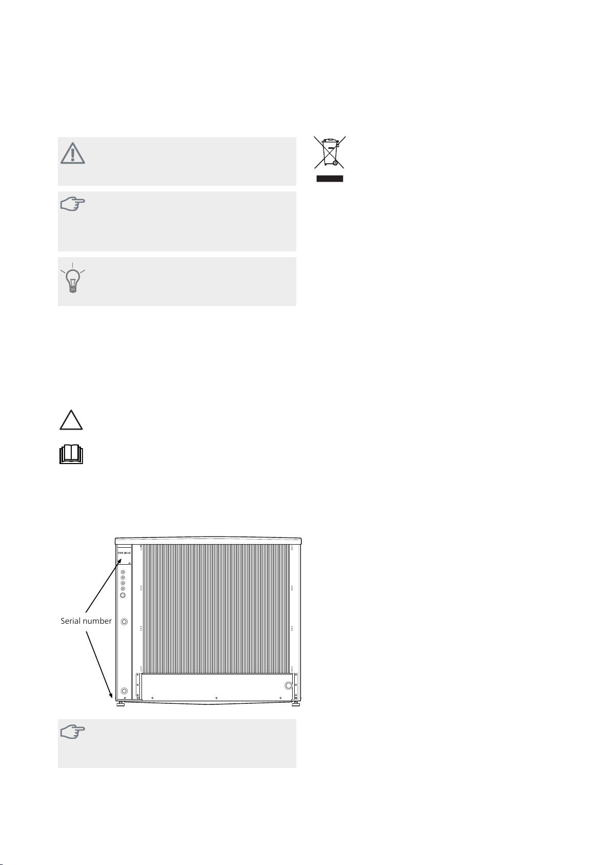
Serial number
The serial number can be found at the top left on the
rear cover and at the bottom on the side.
Caution
You needthe product's(14 digit) serialnumber
for servicing and support.
METROAIR I™Chapter 1 | Important information6
Inspection of the installation
✔
Current regulations require the heating installation to be inspected before it is commissioned. The inspection must
be carried out by a suitably qualified person. Fill in the page for information about installation data in the User
manual.
DateSignatureNotesDescription
Heating medium (page 20)
System flushed
System vented
Particle filter
Shut-off and drain valve
Charge flow set
Electricity (page 22)
Fuses property
Safety breaker
Earth circuit-breaker
Heating cable type/effect
Fuse size, heating cable (F3)
Communication cable connected
METROAIR I addressed (only when cascade connection)
Connections
Main voltage
Phase voltage
Miscellaneous
Condensation water pipe
Insulation condensation water pipe,
thickness (if KVR 10 is not used)
NOTE
Check the connections,main voltage and phase voltage before the machine is started, to prevent damage
to the heat pump electronics.
7Chapter 1 | Important informationMETROAIR I™

Indoor modules
Control modules
METROAIR 330
Stainless Steel, 3 x 400 V
Part no. 153 001 605
METROAIR S20
Control module
Part no. 150 209 601
METROAIR S40
Control module
Part no. 150 409 601
METROAIR I™Chapter 1 | Important information8

LEK
F2120
min 300 mm
LEK
F2120
min
70 mm
2 Delivery and handling
Transport and storage
METROAIR I must be transported and stored vertically.
NOTE
Ensure that the heat pump cannot fall over
during transport.
Ensure that the heat pump cannot be damaged during
transportation.
Assembly
■
Place METROAIR I outdoors on a solid level base that
can take theweight, preferablya concrete foundation.
If concrete slabs are used they must rest on asphalt or
shingle.
■
The lower edge of theevaporator must be atthe level
of the average local snow depth. The concrete foundation or concrete plinthsmust therefore beat least 70
mm high.
■
METROAIR I should not be positioned next to noise
sensitive walls, for example, next to a bedroom.
■
Also ensure that the placement does not inconvenience the neighbours.
■
METROAIR I must not be placed so that recirculation
of the outdoorair can occur. This causes lower output
and impaired efficiency.
■
The evaporator must be sheltered from direct wind / ,
which negativelyaffects the defrosting function.Place
METROAIR I protected from wind / against the evaporator.
■
Some water may drip from the drainage hole below
METROAIR I. Make sure that water can run off by selecting a suitable material underneath METROAIR I
(see page 10).
■
Care must be exercised so that the heat pump is not
scratched during installation.
If there is a risk of snow slip from roof, a protective roof
or covermust be erected toprotect the heat pump, pipes
and wiring.
Do not place METROAIR I directly on the lawn or other
non solid surface.
9Chapter 2 | Delivery and handlingMETROAIR I™
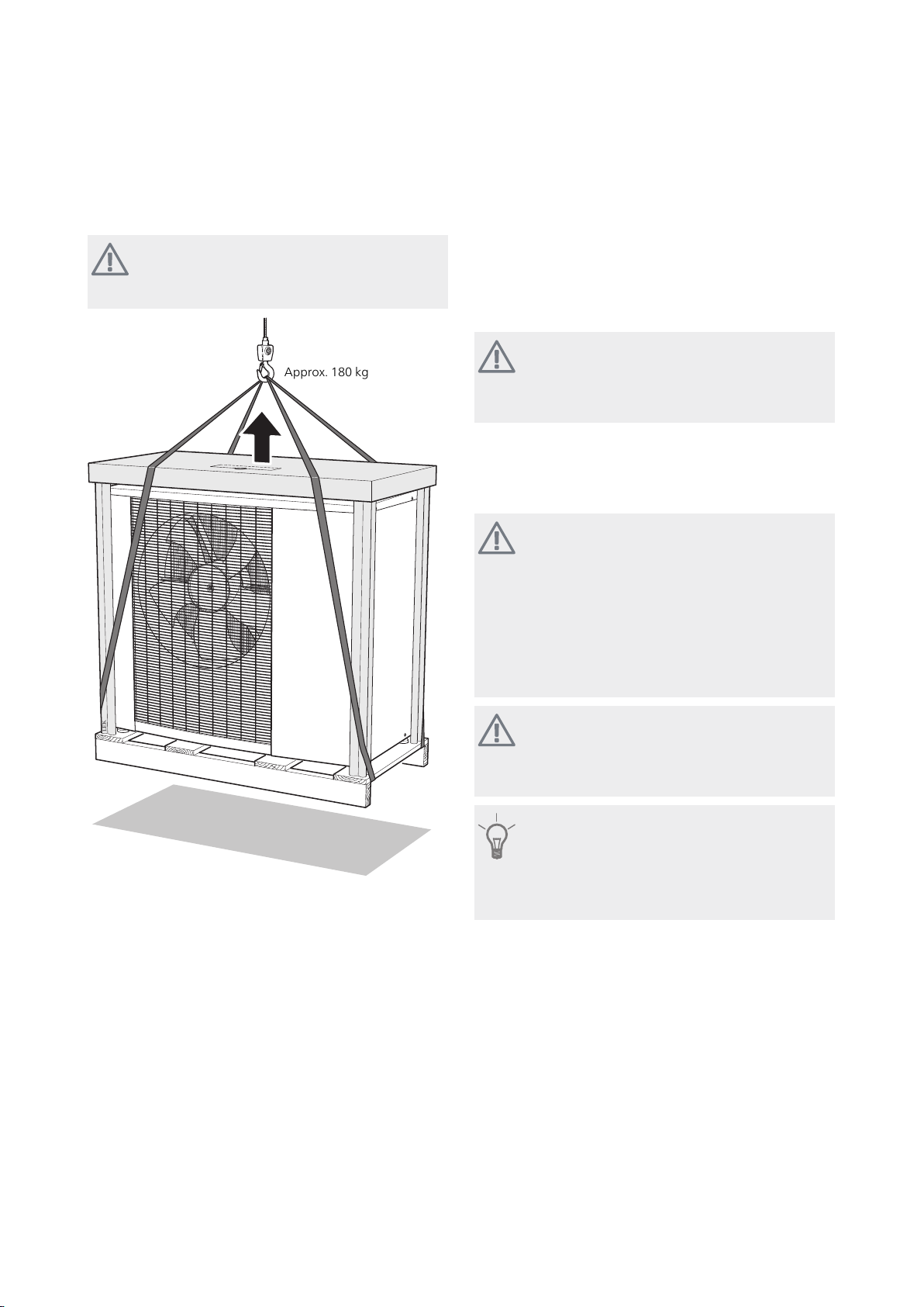
Lift from the street to the set up location
L
E
K
C:a 180 kg
Approx. 180 kg
If the base allows, the simplest thing is to use a pallet
truck to move the METROAIR I to the set up location.
Scrapping
When scrapping, theproduct is removed in reverseorder.
Lift by the bottom panel instead of a pallet!
NOTE
The centre of gravity is offset to one side (see
print on the packaging).
Compressor heater
METROAIR I is equipped with two compressor heaters
that heat the compressor before start-up and when the
compressor is cold.
NOTE
The compressor heater must have been active
for approx. 3 hours before the first start, see
section “Start-up and inspection” on page 34.
Condensation
The condensation water troughcollects and leads away
most of the condensation water from the heat pump.
NOTE
It is important to the heat pump function that
condensation water is led away and that the
drain for the condensation water run offis not
positioned so that it can cause damage to the
house.
Condensation runoff shouldbe checked regularly, especially during the autumn. Clean if
necessary.
NOTE
The electrical installation and wiring must be
carried outunder the supervisionof an authorised electrician.
TIP
Pipe with heating cable for draining the condensation water trough is not included.
To ensure this function the accessory KVR 10
If METROAIR I needs to be transported across soft
ground, such as a lawn, we recommend that a crane is
used that can lift the unit to the installation location.
■
When METROAIR I is lifted with a crane, the packaging
must be undisturbed, see the illustration above.
If a crane vehiclecannot be used the METROAIR I can be
transported on anextended sack truck. METROAIR Imust
■
be taken from its heaviest side and two people are required to lift METROAIR I.
Lift from the pallet to final positioning
Before lifting remove the packaging and the securing
■
■
strap to the pallet.
Place lifting straps around each machine foot. Lifting
from the pallet to the base requires four persons, one
for each lifting strap.
■
■
should be used.
The condensation water (up to 50 litres/24 hrs) that
collects inthe trough should berouted away by apipe
to an appropriate drain, it is recommended that the
shortest outdoor stretch possible is used.
The section of the pipe that can be affected by frost
must be heated by the heating cable to prevent
freezing.
Route the pipe downward from METROAIR I.
The outlet of the condensation water pipe must be at
a depth that is frost free or alternatively indoors (with
reservation for local ordinances and regulations).
Use a water trap for installations where air circulation
may occur in the condensation water pipe.
The insulation must seal against the bottom of the
condensation water trough.
METROAIR I™Chapter 2 | Delivery and handling10
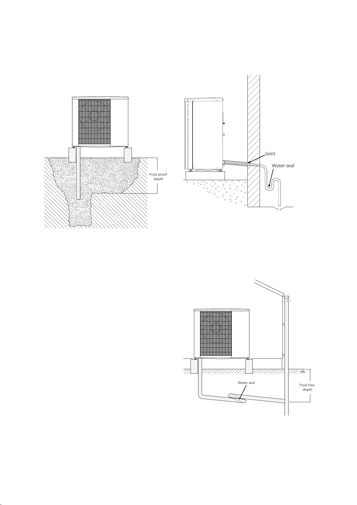
Recommended alternative for leading off
Frostfritt djup
F2120
Frost proof
depth
Water seal
Joint
LEK
F2120
Frostfritt
djup
Frost free
depth
Water seal
condensation water
Stone caisson
If the house has a cellar the stone caisson must be positioned so that condensation water does not affect the
house. Otherwise the stone caisson can be positioned
directly under the heat pump.
The outlet of the condensation water pipe must be at
frost free depth.
Drain indoors
The condensation water is lead to an indoor drain (subject to local rules and regulations).
Route the pipe downward from METROAIR I.
The condensation water pipe must have a water seal to
prevent air circulation in the pipe.
KVR 10 spliced as illustrated. Pipe routing inside house
not included.
Gutter drainage
The outlet of the condensation water pipe must be at
frost free depth.
Route the pipe downward from METROAIR I.
The condensation water pipe must have a water seal to
prevent air circulation in the pipe.
11Chapter 2 | Delivery and handlingMETROAIR I™

Caution
If none of the recommended alternatives is
used goodlead off of condensationwater must
be assured.
METROAIR I™Chapter 2 | Delivery and handling12
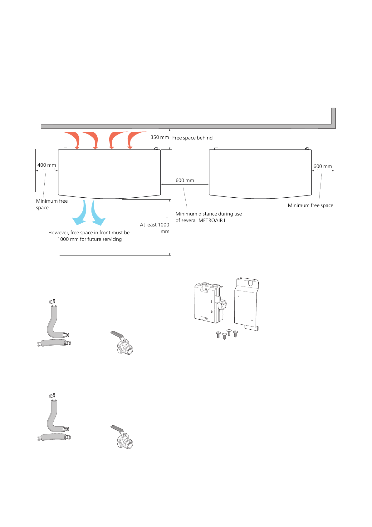
Installation area
350 mm
Fritt utrymme bakom
Fritt utrymme framför
dock 1000 mm för ev. framtida service
Min. avstånd
vid användning
av flera F2300
600 mm
1000 mm
400 mm
Minimalt
fritt utrymme
600mm
Minimalt
fritt utrymme
Minimum free
space
However, free space in front must be
1000 mm for future servicing
Minimum free space
Minimum distance during use
of several METROAIRI
600 mm
600 mm
At least 1000
mm
Free space behind
350 mm
400 mm
LEK
LEK
The distance between METROAIR I and the house wall
must be at least 350 mm. The free space above METROAIR I must be at least 1,000 mm. The free space in
front must be at least 1,000 mm for future servicing.
Supplied components
METROAIR I 8, METROAIR I 12
2 xflexible pipes(DN25, G1")
with 4 x gaskets.
METROAIR I 16, METROAIR I 20
2 x flexible pipes (DN25, G1
1/4") with 4 x gaskets.
Filterball (G1").
Filterball (G1 1/4").
1 xcircuit breakersincl. screw
and plate
13Chapter 2 | Delivery and handlingMETROAIR I™
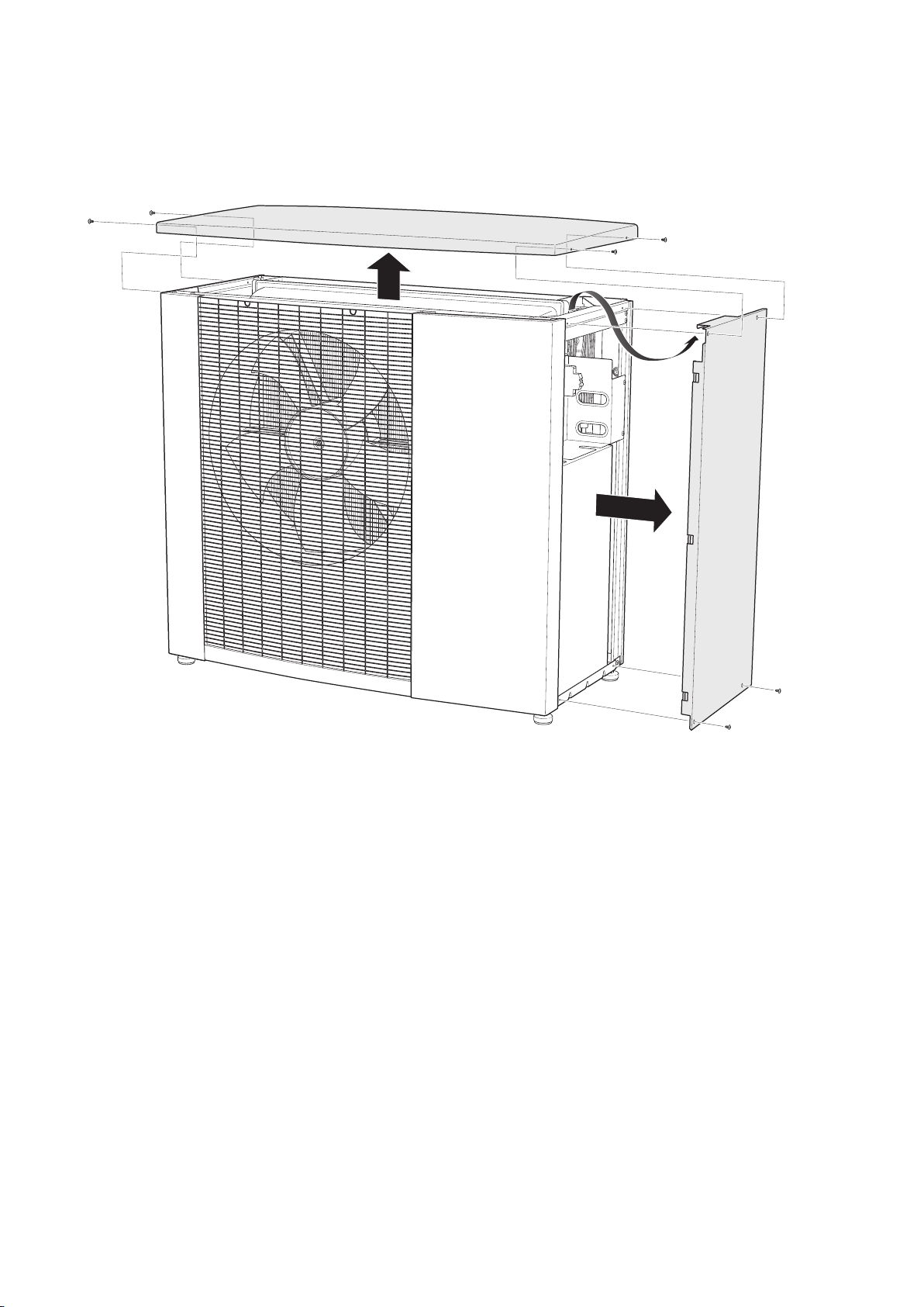
Removing the side cover and top panel
L
EK
METROAIR I™Chapter 2 | Delivery and handling14

LEK
GQ1
AA2
UB1
BT12
EP2
XL1
BT3
XL2
HS1
XL21
BT84
QN1
QN4
RM1
QN2
BP11
QN34
BT15
BT14
EB10
QA40 GQ10
BT17
RA1
BP9
BP1
BP2
BP8
XL20
BT81
HQ9
CA1
X6
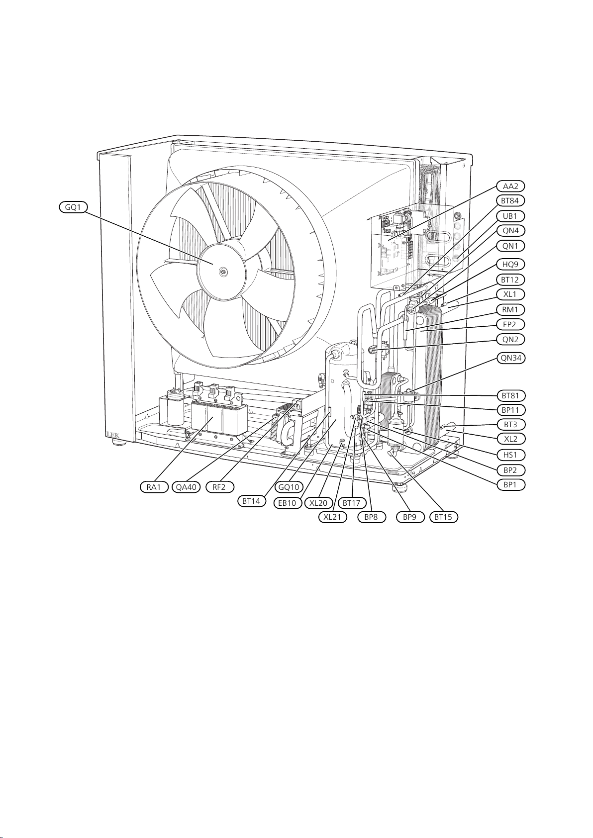
3 The heat pump design
General
METROAIR I (1x230V)
15Chapter 3 | The heat pump designMETROAIR I™
METROAIR I (3x400V)
LEK
GQ1
AA2
UB1
BT12
EP2
XL1
BT3
XL2
HS1
XL21
BT84
QN1
QN4
RM1
QN2
BP11
QN34
BT15
BT14
EB10
QA40 GQ10
BT17
RF2RA1
BP9
BP1
BP2
BP8
XL20
BT81
HQ9
METROAIR I™Chapter 3 | The heat pump design16
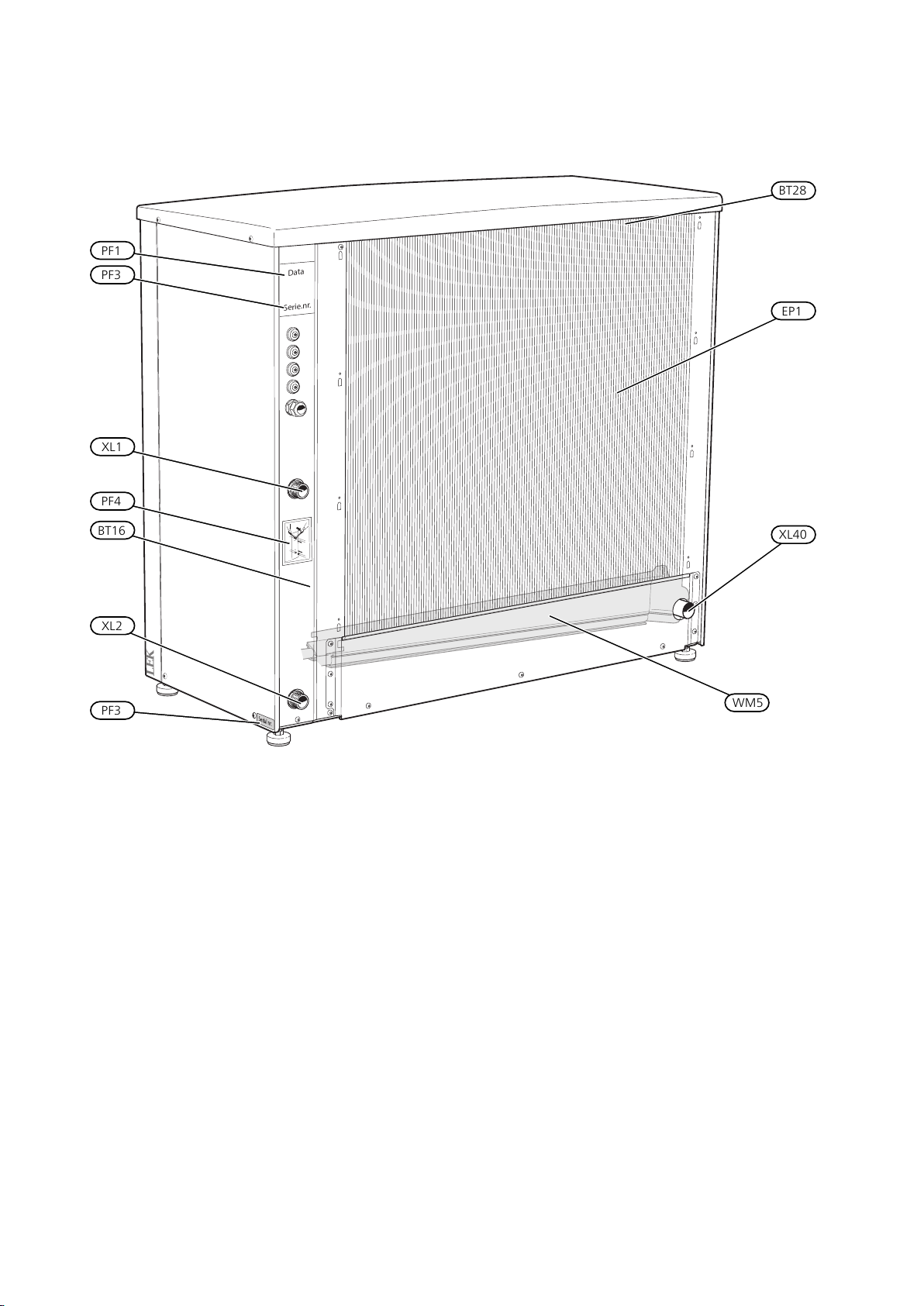
LEK
Data
Serie.nr.
Art.nr.
711453
O
UT
IN
PF4
BT16
PF1
BT28
EP1
WM5
XL40
XL1
XL2
PF3
PF3
17Chapter 3 | The heat pump designMETROAIR I™

Pipe connections
Connection, heating medium out of METROAIR IXL1
Connection, heating medium in to METROAIR I,XL2
Service connection, high pressureXL20
Service connection, low pressureXL21
Connection, drain condensation water troughXL40
Sensors etc.
High pressure pressostatBP1
Low pressure pressostatBP2
Low pressure transmitterBP8
High pressure sensorBP9
Pressure sensor, injectionBP11
Temperature sensor, returnBT3
Temperature sensor, condenser supply lineBT12
Temperature sensor, hot gasBT14
Temperature sensor, fluid pipeBT15
Temperature sensor, evaporatorBT16
Temperature sensor, suction gasBT17
Temperature sensor, ambientBT28
Temperature sensor, injection, EVI compressorBT81
Temperature sensor, suction gas evaporatorBT84
Miscellaneous
Type platePF1
Serial numberPF3
Sign, pipe connectionsPF4
Cable gland, incoming supplyUB1
Condensation water troughWM5
Electrical components
Base cardAA2
Capacitor (1x230V)CA1
Compressor heaterEB10
FanGQ1
InverterQA40
Harmonic filter (3x400V)RA1
Choke (1x230V)RA1
EMC filter (3x400V)RF2
Terminal block (1x230V)X6
Cooling components
EvaporatorEP1
CondenserEP2
CompressorGQ10
Particle filterHQ9
Drying filterHS1
Expansion valveQN1
Bypass valveQN4
4-way valveQN2
Expansion valve, subcoolingQN34
Non-return valveRM1
Designations in component locations according to standard IEC 81346-2.
METROAIR I™Chapter 3 | The heat pump design18
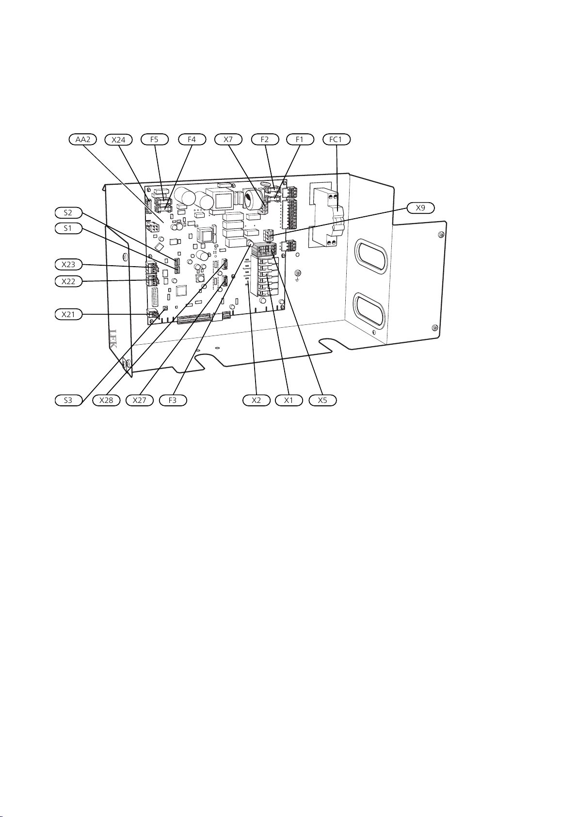
Distribution box
LEK
AA2 FC1
X24
F5 F4 X7 F2 F1
S2
S1
X23
X22
X21
X28 X27 F3 X2 X1 X5
X9
S3
Electrical components
Base cardAA2
Terminal block, incoming supplyX1
Terminal block, compressor supplyX2
Terminalblock, external control voltageX5
Terminal block, 230V~X7
Terminal block, connection KVRX9
X21
Fuse, operating 230V~F1
Fuse, operating 230V~F2
Fuse for external heating cable KVRF3
Fuse, fanF4
FC1
Fuse, fanF5
Miniature circuit breaker (Replacedwith automat-
ic protection (FB1) when installing accessory
KVR 10.)
S1
DIP switch, addressing heat pump during multi
operation
DIP switch, different optionsS2
Reset buttonS3
Terminal block, Compressor blocking,
Tariff
Terminal block, communicationsX22
Terminal block, communicationsX23
Terminal block, fanX24
Terminal block, expansion valve QN1X27
Terminal block, subcooling QN34X28
Designations in component locations according to
standard IEC 81346-2.
19Chapter 3 | The heat pump designMETROAIR I™
0
1
2
3
4
5
6
7
8
9
10
11
12
13
14
15
0
0,05
0,1 0,15 0,2 0,25 0,3 0,35 0,4 0,45 0,5 0,55 0,6 0,65 0,7 0,75 0,8 0,85 0,9
Tryckfall
[kPa]
Tryckfall F2120
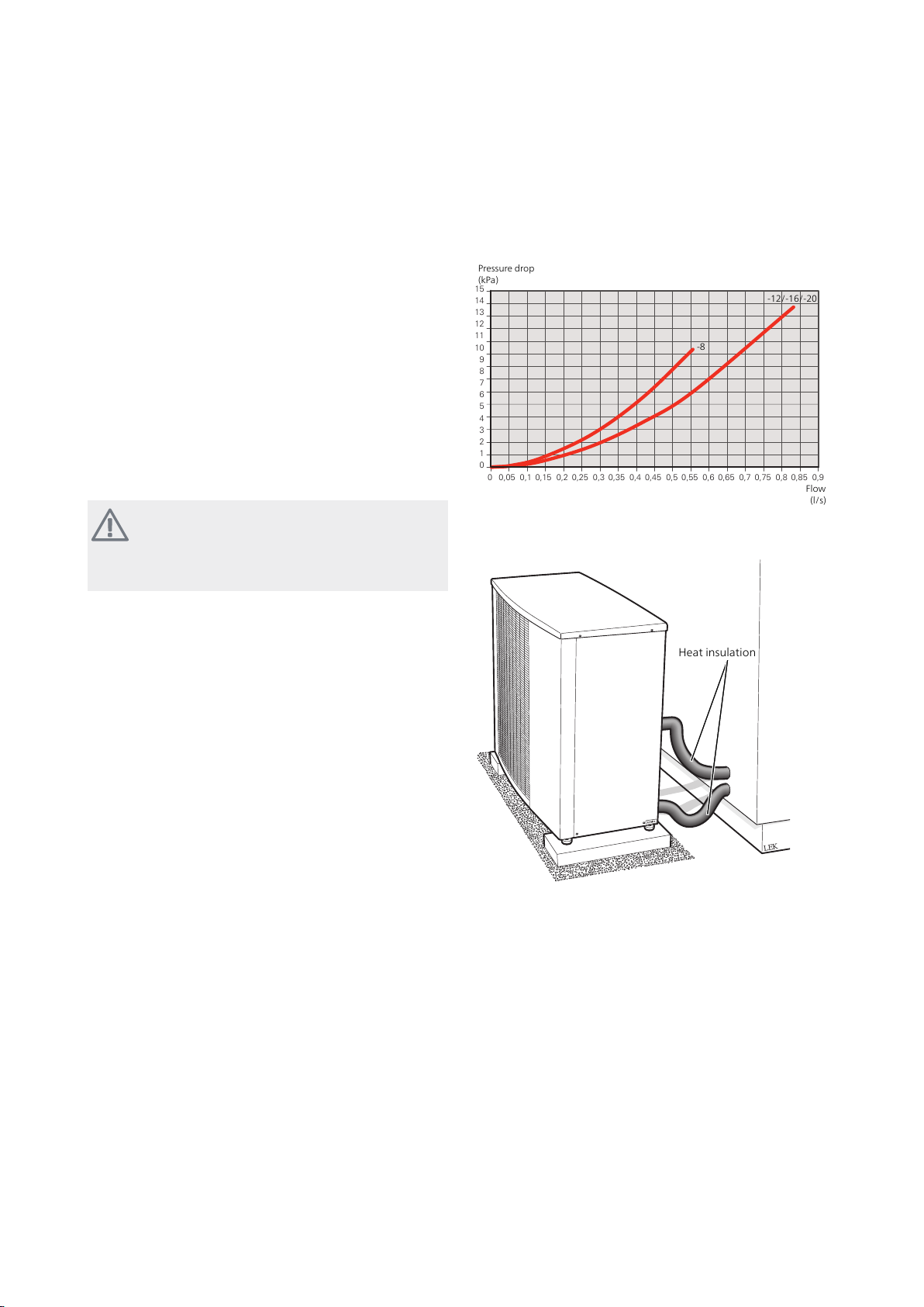
Pressure drop
(kPa)
Flow
(l/s)
-12/-16/-20
-8
LEK
Heat insulation
4 Pipe connections
General
Pipe installation must be carried out in accordance with
current norms and directives.
METROAIR Ican only operate up toa return temperature
of about 55 °C and an outgoing temperature of about
65 °C from the heat pump.
METROAIR Iis not equipped withexternal shut offvalves
on the water side; these must be installed to facilitate
any future servicing. The return temperature is limited
by the return line sensor.
Water volumes
Depending onthe size of METROAIR I,an available water
volume isrequired to prevent shortoperating times and
to enable defrosting. For optimal operation of METROAIR I, a minimum available water volume of 10 litres
times the size number is recommended. E.g. METROAIR I-12: 10 litres x 12 = 120 litres.
NOTE
The pipework must beflushed beforethe heat
pump is connected, so that any contaminants
do not damage the components.
Pipe coupling heating medium
Pressure drop, heating medium side
METROAIR I-8, -12, -16, -20
Heat insulation
circuit
■
The heat pump must be vented by the upper connection (XL1) using the venting nipple on the enclosed
flexible hose.
■
Install the enclosed particle filter before the inlet, i.e.
the lower connection (XL2) on METROAIR I.
■
All outdoor pipes must be thermally insulated with at
least 19 mm thick pipe insulation.
■
Install shutoffand drainvalves sothat METROAIR I can
be emptied in the event of prolonged power failures.
■
The supplied flexible hoses act as vibration dampers.
The flexible pipes are fitted so an elbow is created,
thus acting as vibration damping.
Charge pump
The charge pump (not included in the product) is
powered and controlled fromthe indoormodule/control
module. Ithas a built-inanti-freezing function andmust
therefore not be switched off when there is a risk of
freezing.
At temperatures below +2 °C the charge pump runs
periodically, to prevent the water from freezing in the
charge circuit. The function also protects against excess
temperatures in the charge circuit.
METROAIR I™Chapter 4 | Pipe connections20
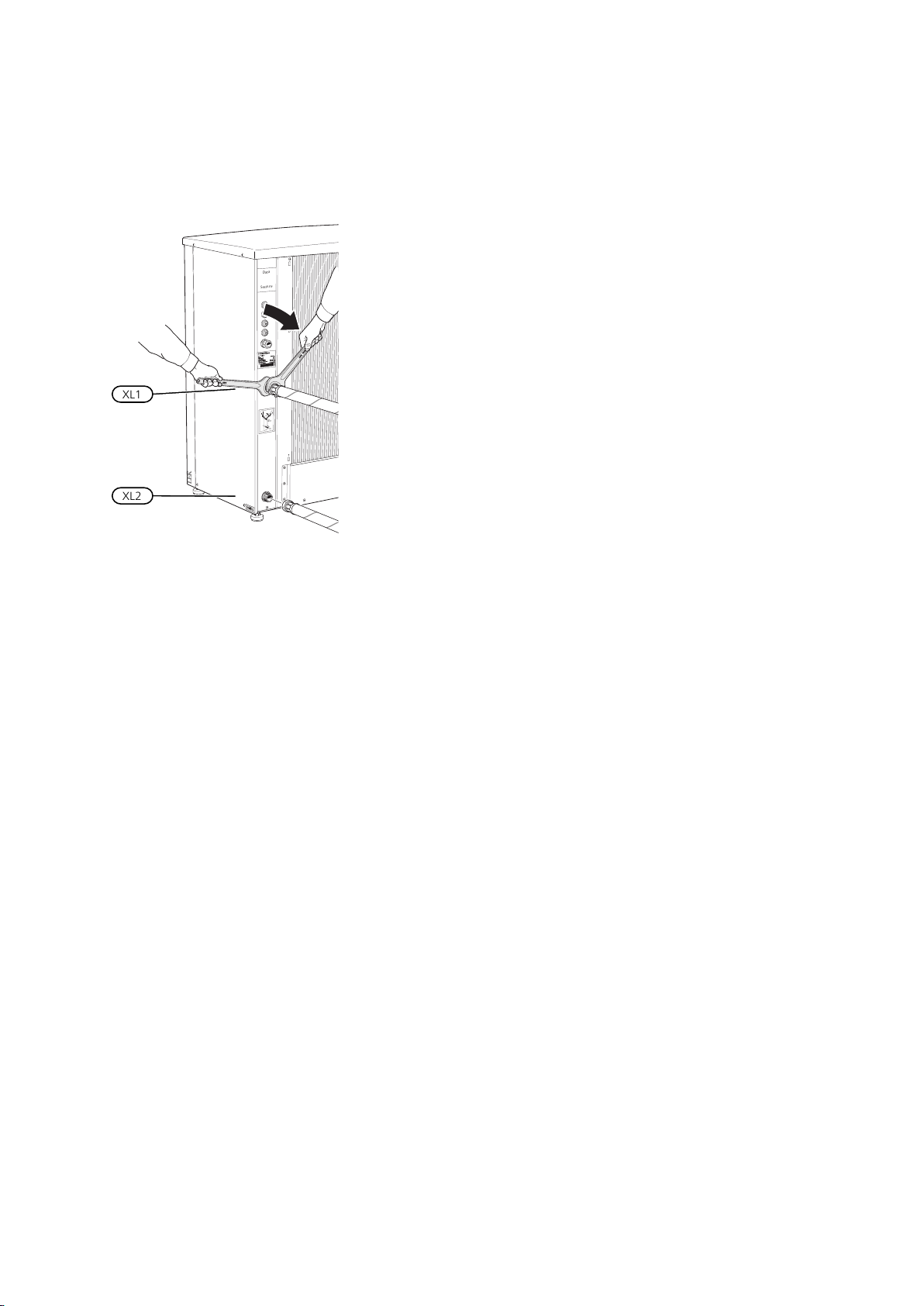
Installing flex hoses
LEK
Data
Serie.nr.
A
rt
.
nr
. 711453
OUT
IN
XL1
XL2
21Chapter 4 | Pipe connectionsMETROAIR I™
5 Electrical connections
General
■
The heat pump must not be connected without the
permission of the electricity supplier and must be
connected underthe supervisionof a qualified electrician.
■
If METROAIRI is fused witha miniature circuit breaker,
it must have at least motor characteristic ”C”. For MCB
size see "Technical Specifications".
■
METROAIR I does not include an omnipolar circuit
breaker on the incoming power supply. The heat
pump’s supply cable must be connected to a circuit
breaker with at least a 3 mm breaking gap. When the
building is equipped with an earth-fault breaker, the
heat pump should be equipped with a separate one.
The earth-fault breaker shouldhave a nominaltripping
current of nomore than30 mA.Incoming supply must
be 400V3N~ 50Hz viaelectrical distribution unitswith
fuses.
For 230V~ 50Hz, the incoming supply must be 230V~
50Hz via distribution box with fuses.
■
If an insulation test is to be carried outin the building,
disconnect the heat pump.
■
If the control is to be supplied separately from other
components in the heat pump (e.g. for tariff connection), a separate operating cable must be connected
to terminal block (X5).
■
The routing of cables for heavy current and signals
should be made out through the cable glands on the
heat pump's right-hand side, seen from the front.
■
The communication cable must be a three core,
screened cable andbe connectedbetween METROAIR I
terminal block X22 and the indoor module/control
module.
■
Connect the charge pumpto the indoor module/control module. See where the charge pump must be
connected in the installation manual for your indoor
module/control module.
NOTE
If the supply cable is damaged, only METROTHERM, its service representative or similar
authorised person may replace it to prevent
any danger and damage.
NOTE
Electrical installation and any servicing must
be carried out under the supervision of a qualified electrician. Disconnect the current with
the circuit breaker before carrying out any servicing. Electrical installation and wiring must
be carried out in accordance with the national
stipulations in force.
NOTE
Check theconnections, main voltage andphase
voltage before startingthe machine toprevent
damage tothe air/water heat pump’s electronics.
NOTE
The live external control must be taken into
consideration when connecting.
METROAIR I™Chapter 5 | Electrical connections22
 Loading...