

Metro Therm METROAIR AQUA HPM User Manual
HEAT PUMPS
Manual
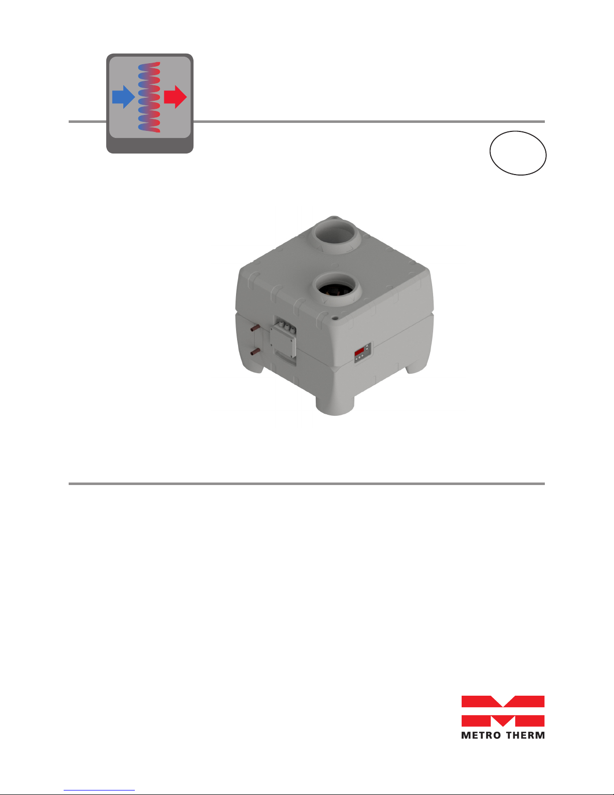
METROAIR AQUA
HEAT PUMP MODULE
DOMESTIC HOT
WATER HEAT PUMP
08:965-1609
EN
2
METROAIR AQUA HEAT
PUMP MODULE (HPM)
METRO article number: 156002601

3
Table of Contents
1 Transport 6
1.1 Delivery mode 6
1.2 Storage 6
1.3 Transport with forklift 6
1.4 Unloading the heat pump 6
2 Dimensions 7
3 About the product 8
3.1 General 8
3.2 Scope of delivery 8
3.3 Product description 8
3.4 Operation of the METROAIR AQUA 8
3.5 Technical data 9
3.6 Performance data 9
3.7 Refrigerant circuit – description 10
3.8 Requirements for the water circuit 11
3.8.1 Water circuit - diagram 12
3.9 Electrical diagram Optima 172 Control 13
3.10 Fan capacity 14
4 Before Installation and start up 15
4.1 Important safety instructions 15
4.1.1 Cooling system – safety instructions 15
4.1.2 Electrical circuit – safety instructions 15
4.1.3 Water circuit – safety instructions 15
4.1.4 Users 15
5 Installation 16
5.1 Location 16
5.2 Set-up sequence 16
5.3 Water connections 17
5.4 Location of connecting pipes 17
5.5 Connection of condensate drain 17
5.6 Air intake, air exhaust and connections 18

4
6 Commissioning 19
6.1 Leak test 19
6.2 Commissioning of the water circuit 19
6.3 Commissioning of the air circuit 19
6.4 Commissioning of the electrical circuit 19
7 Controls and Operations 20
7.1 Control panel Optima 170 20
7.2 Operation 20
7.3 Main Menu 20
7.3.1 Display view (main menu) 22
7.4 Service menu 22
7.4.1 Changing settings in the service menu 22
7.4.2 Service menu points 22
7.5 Table for set points 31
7.6 Table for defrosting 32
7.7 Functional description 32
7.7.1 Controlling Domestic hot water heat pump with Optima 170 33
7.7.2 Performance 33
7.7.3 The function of the heat pump 33
7.7.4 Water heating 34
7.7.5 Fan operation 34
7.7.6 Defrosting 36
7.8 Safety features 36
7.8.1 High pressure switch 36
7.8.2 Safety breakers 36
7.9 Alarms 36
7.9.1 PE: High pressure switch alarm 36
7.9.2 Er6: Atypical evaporator temperatures 36
Table of Contents

5
8 Maintenance 37
8.1 Environmental requirements 37
8.2 Cooling system and fan 37
8.3 Condensation and condensate drain 37
8.4 Water circulation and water tank 37
8.4.1 Pressure relief valve 37
9 Disassembly/decommissioning 38
10 Troubleshooting 39
10.1 The heat pump does not supply hot water 39
11 Warranty provisions 40
12 Declaration of conformity 41
13 Product and installer information 42

6
1 Transport
Immediately upon receipt, examine the Heat Pump Module (HPM) to make sure that it is intact
and undamaged. If not, inform this to the shipping company immediately. All shipments are the
responsibility of the recipient unless otherwise agreed.
1.1 Delivery mode
METROAIR AQUA HPM is delivered without condensate drain tube and the safety equipment for
the water circuit.
1.2 Storage
METROAIR AQUA HPM must be stored and transported upright free of water and within its
packaging.
Transport and storage may take place at temperatures between -10 °C and +50 °C. If the unit
has been transported or stored at sub-zero temperatures leave the unit at room temperatures
for 24 hrs before commissioning.
1.3 Transport with trolley
When transporting the METROAIR AQUA HPM by trolley the unit shall be in its disignated transportation box and transportet upright. The box shall be lifted from the disignated side.
Make sure that the trolley does not damage the cabinet or the various connections.
1.4 Tilting of unit
When carefully and manually transporting the METROAIR AQUA HPM over a short distance to
its final location the unit can be tilted up to 45°. If this limit is exceeded, the METROAIR AQUA
must be left in its normal upright position for at least 1 hour before it is started.
7
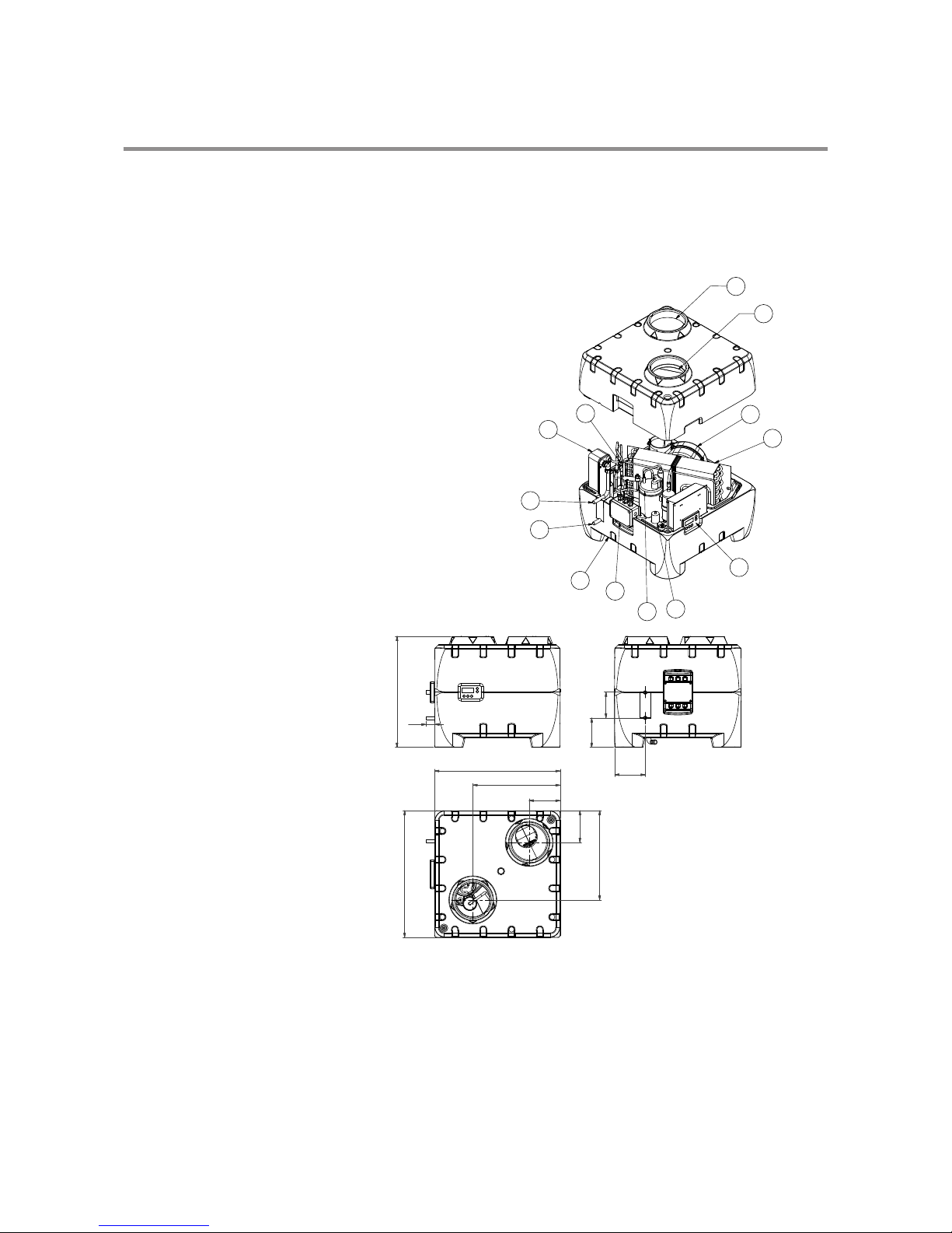
2 Dimensions
1 Inlet air Ø 160 mm
2 Outlet air Ø 160 mm
3 Cold water connection Ø15
4 Hot water connection Ø15
5 Circuit board
6 Electrical junction box
7 Condensate drain 3/4” hose connection
8 Condenser
9 Compressor
10 Capacitor
11 Evaporator
12 Fan
13 Thermostatic expansion valve
General arrangement METROAIR AQUA HPM
All dimensions in mm.
1
2
3
4
5
6
508
140
134
118,5
575
580
142
145
408
400
41
5
12
11
9
8
10
7
6
4
3
1
2
13

8
3 About the product
3.1 General
The heat pump module (HPM) has been designed and produced according to all relevant EU
guidelines (please also refer to the EEC-declaration of conformity).
3.2 Scope of delivery
• Hot water heat pump unit with built-in control.
• External temperature sensors T7 and T8.
• Manual including installation guidelines, operating instructions and technical data.
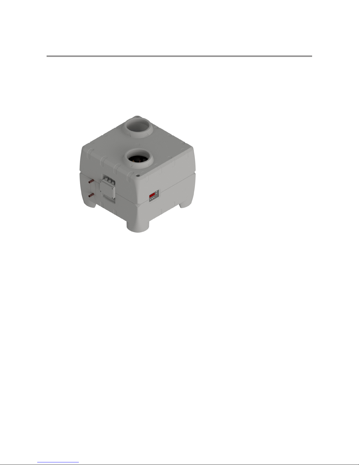
3.3 Product description
The METROAIR AQUA HPM is a hot water heat pump, ready made for installation. It has
been designed for domestic hot water application but can also be used for e.g. space heating
applications. It consists of cabinet, components for refrigerant, air and water circuits as well as
control panel, and control and monitoring equipment designed for automatic operation.
The application area and operating principles of the heat pump are specified in this manual.
3.4 Operation of the METROAIR AQUA HPM
The control starts the compressor when hot water is needed. The compressor operates until the
water in the water tank (T8) reaches the set temperature. Usually, the METROAIR AQUA HPM
can produce enough hot water to cover the need of a household of 4 persons.
If the METROAIR AQUA HPM is not able to produce enough domestic hot water, an electrical
immersion heater can be installed in the adjacent water tank and activated by the HPM.
This way more domestic hot water can be produced. It is possible to set the temperature to
which the electrical immersion heater should heat the water. The electrical immersion heater
should only be used when there is a need, as it consumes significantly more energy that the
compressor.
Any work carried out on
this unit must only be done by
skilled personnel.
Take all necessary precautions to
avoid accidents.
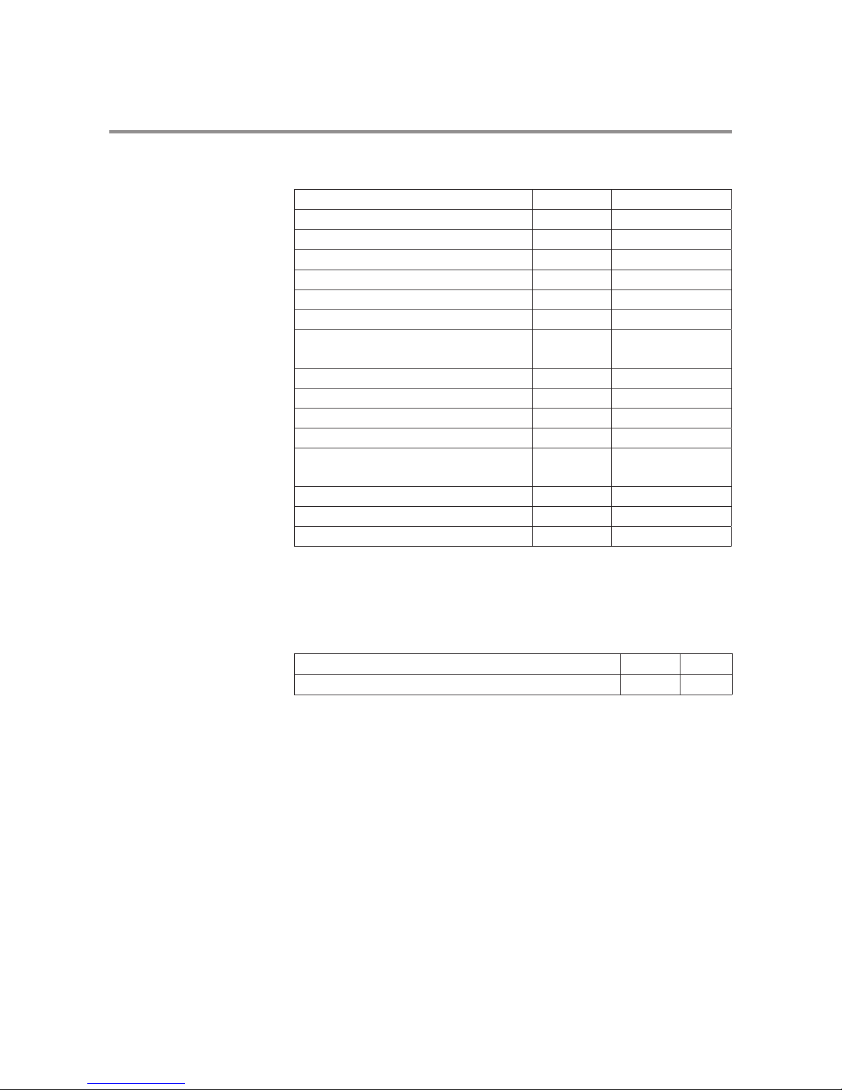
9
Dimensions (LxWxH) mm 580x575x508
Weight kg 30
Air duct connections mm Ø160
Water connections (compression fittings) mm Ø15
Condensate outlet (hose connection) “ 3/4
Maximum allowed water pressure MPa 1.0
Maximum allowed water temperature in tank °C 90
Allowed flow range external circulation pump
(not included)
I/hr 200-600
Refrigerant/quantity -/kg 134a/0.65
Electrical connections V/Hz 230/50 (L1, N, G)
Fuse size A 10 (13)
Max. water temperature (heat pump only) °C 60
Max. water temperature (heat pump and immersion heater)
°C 65
Air flow range (@100 Pa) m3/h 100-330
Temperature range for compressor operation °C -5 – + 35
Sound level 2 m in front om unit at 100% air flow dB(A) 44
COP acc. to EN-16147 class L , 7°C inlet air - 2.4
COP acc. to EN-16147 class L , 20°C inlet air - 3.3
3.6 Performance data
Performance specified for heating of domestic water from 10°C (cold water) to 52.5°C (domestic water) in a connected water tank of 300 l and extract air temperature 7°C:
3.5 Technical data
10
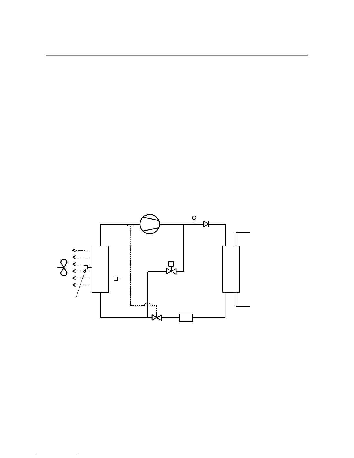
3.7 Refrigerant circuit – description
The cooling system is optimized for extracting the heat from the inlet air. Via the cooling system
the extracted heat is transferred to the water. The process is only possible with the addition of
additional external energy in the compressor. The cooling system is a closed system where the
HCFC-free refrigerant R134a is the energy carrier.
In the evaporator, heat is absorbed from the air and transferred to the refrigerant at low evaporation temperature. Refrigerant in gaseous form is fed to the compressor, in which it is raised up
to a higher pressure and temperature level and transported to the condenser. In the condenser
the refrigerant condense and the heat absorbed in the evaporator plus some of the compressor
energy is transferred to the water.
Finally the high condensing pressure is throttled to the evaporating pressure using an expansion
valve and the refrigerant can again absorb heat from the extract air in the evaporator.
3.7.1 Refrigerant circuit – diagram
3 About the product
Air temp
sensor
(T5)
Evaporating temp
sensor (T6)
Evapo
rator
Filter drier
Compressor
Thermostatic
expansion
valve
HP-switch
Condenser
Cold water
inlet
Hot water
outlet
Solonoid valve
Checkvalve
Fan
Hot water outlet

11
3.8 Requirements for the water circuit
The water circuit must be constructed in accordance with local norms and standards. The water
used must be of drinking water quality when charged to the system. Material compatibility in
the whole system must be ensured.
The pipe sizes for on-site installation shall be defined based on the available water pressure
as well as the expected pressure loss in the pipe system. The water circuit shall be designed
according to the drinking water installation regulative in force. Incorrect material combinations
in the water circuit can lead to corrosion damage due to galva-nic corrosion. This requires special
attention when using galvanized components and components that contain copper.
As for all pressurized vessels the heat pump associated water tank has to have an approved
safety valve (pressure setting depending on local rules and regulations) and a non return/
check valve on the cold water inlet. Max. working pressure is 1.0 MPa (10 bar) and max. inlet
temperature is 65°C. Dirt must be avoided in the pipe system (if necessary flush the pipes before
the heat pump is connected)!
12
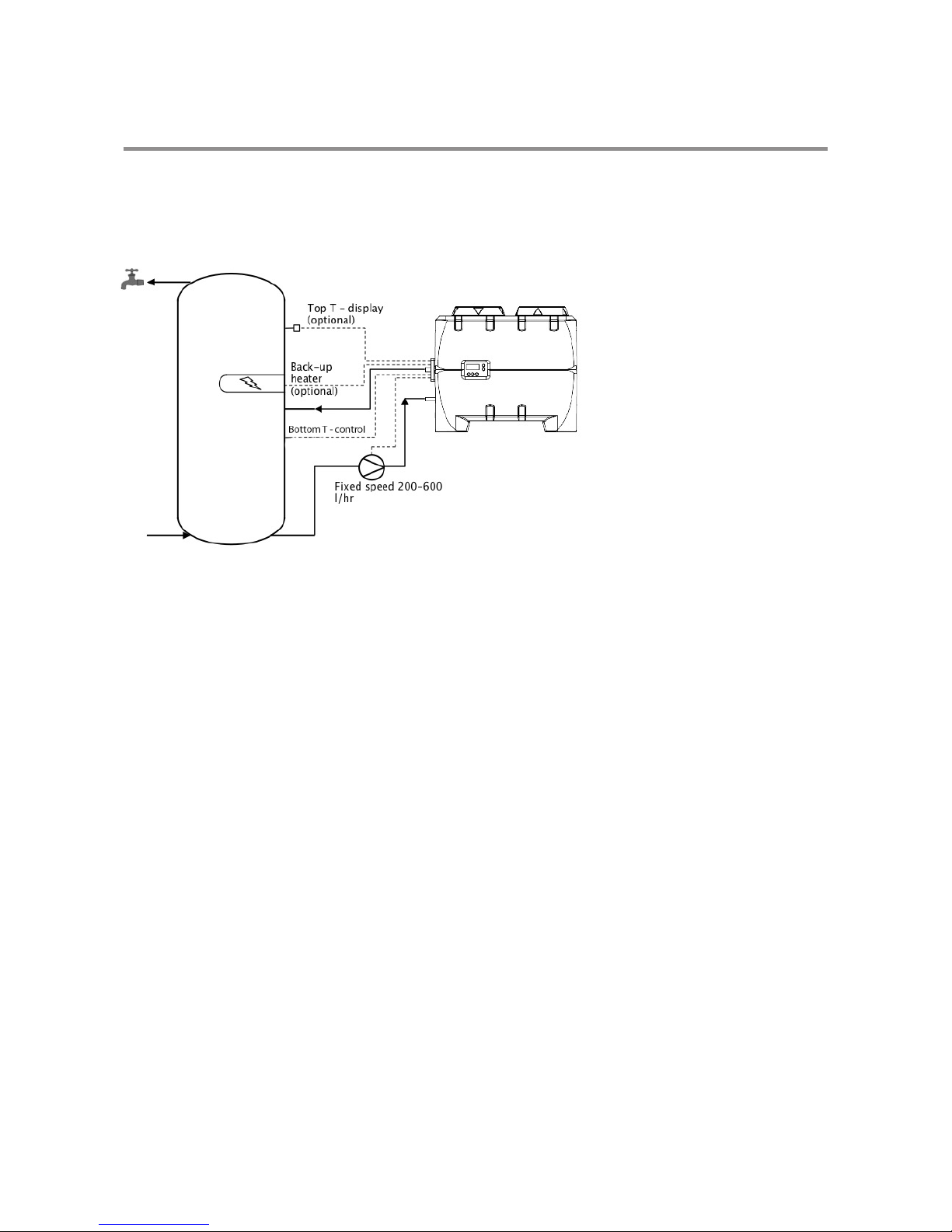
3.8.1 Water circuit - diagram
3 About the product
The HPM heats up the water by the principle of repeatable circulations to reach set point temperature, typically, 5-15 passes to fully heat op a water tank starting with cold water.
Therefore the following should be observed during installation:
- The hot water inlet from the heat pump shall be placed, e.g., 1/3 down from the top to ensure
that hot water is available for use while the heat pumpe heats up the lower 2/3 of the water
tank.
- The heat pump control sensor, T8, shall be located around the how water inlet from the heat
pump. If a higher readyness of hot water is required the sensor location can be lowered.
- Sensor T7 can be used for optional display of temperature in the top of the tank.
- If an optional electrical heater is controlled by the HPM sensor T7 shall be installed ABOVE the
electrical heating element sensor sensor T7 is controling sensor for the electrical heater. It is
recommended to use a safety breaker which will disengage at 80°C.
- A fixed speed pump shall be installed on the cold water return to the HPM. A pump rate
between 200-600 l/h is advisable. Higher pump rates gives better HPM performance but also
consumes more circulation pump power.
13
EP
M1
KP
NT
Skal jordforbindes jvt. stærkstrøms reglementet
Must have earth connection
Muss erdung haben
Tilslutning Datalog
Connection Datalog
Anschluss Datalog
MA4-
NT-
EP-
P-
T5-
T6-
T7-
T8-
T9-
T10-
80°C
Føler før køleflade
Sensor before the evaporator
Fühler bevor die kühlfläche
Føler Køleflade
Sensor on the evaporator
Kühlfläche fühler
Føler tank top
Sensor in the top of the tank
Oberer speicher fühler
Føler tank bund
Sensor in the bottom of the tank
Unterer Speicherfühler
Ekstra funktion
Ekstra Funktion
Extra Funktion
Føler start/stop
Sensor start/stop
Fühler start/stop
Tilslutning Datalog
Connection Datalog
Anschluss Datalog
T5-
T6-
T7-
T8-
T9-
T10-
Magnetventil afrimning
Magnetventile Abtau
Solonoid valve Defrost
Nettilslutning 1x230V 50Hz
sikring max. 13 Amp
end main: 1x230V 50Hz
fuse mx. 13 Amp
Netzende: 1x230V 50Hz
sicherung max 13 Amp
El-patron 1,5kW
Electric heating element 1,5kW
Heizstab 1,5kW
Højtrykspressostat
High pressure switch
Hochdruckpressostat
12 12
H1
12 12
H2
12
12
H6
1212
H7
1212
H8
12341234
L4
12341234
L5
12 3
12 3
H3
12 312 3
H5
12341234
L6
T7
T8
VL1
MA4
BUBNPE BUBNPE
M1
C
PE
R
S
C
PE
R
S
PE
121
2
1
2
1
2
1
1
1
1
1
1 1
1
1
1
1
1
11
2 2
2
2
2
2
2
2
2
2
2
2
2 2
3
3
3
3
3
3
3
3
344
4
4
4
4
5
PE PEPE PEPE PEPE PE
Q1=1,6A Q2=5A
H1
H2
H3
H4
H5
H6
H7
H8
L1
L2
L4
L5
L3 L6
F
F
F
F
F
F
F
N
N
N
N
N
N
1
1
1
1
1
1 1
1
1
1
1
1
11
2 2
2
2
2
2
2
2
2
2
2
2
2 2
3
3
3
3
3
3
3
3
344
4
4
4
4
5
PE PEPE PEPE PEPE PE
1234 1234
L2
BuBu
-M2
YeYe
1234 1234
L1
12345 12345
L3
T5
T6
M1-
EC blæser forsyning
EC fan supply
EC Lüfter strom
M2-
EC blæser kontrol
EC fan control
EC Lüfter regeln
T10
T9
Aux relæ
Aux Relay
Aux Relais
PEPE
1122
H4
PEPE
Pumpe
Pump
Pumpe
Included
Excluded
Excluded
Included
Included
Excluded
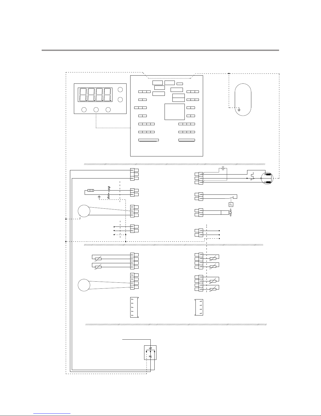
3.9 Electrical diagram Optima 172 Control
14
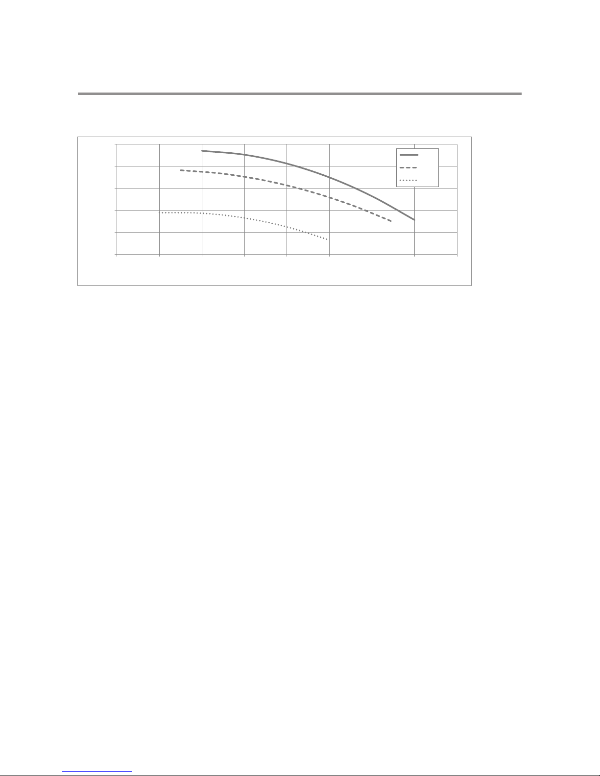
0,0
50,0
100,0
150,0
200,0
250,0
0 50 100 150 200 250 300 350 400
Pressure [Pa]
Air volume flow [m3/h]
100%
75%
50%
3.10 Fan capacity
It is recommended to keep the external pressure loss below 100 Pa.
3 About the product
 Loading...