

Metro Therm METROAIR AQUA 201, METROAIR AQUA 301 S User Manual
1
DOMESTIC HOT WATER HEAT PUMP
Manual
METROAIR AQUA 201
METROAIR AQUA 301 S
08:956-1806

2

3
TABLE OF CONTENTS
Introduction .....................................................................4
1. About the product ...............................................................4
2. Transport, Handling and Delivery ............................................. 13
3. Positioning .................................................................... 15
4. Water Circuit ..................................................................17
5. Air system .....................................................................21
6. Electric Connections ..........................................................24
7. Control and Operation ........................................................25
8. Maintenance ..................................................................42
9. Disassembly & Decommissioning .............................................45
10. Troubleshooting ...............................................................46
11. Warranty ......................................................................48
12. Declaration of conformity ....................................................50
13. Product and installer information ............................................51

4
INTRODUCTION
The aim of this manual is to give information, instructions and warnings on the heat
pump water heater. The manual is to be used by installers and plumbers as well as by
end users, since it contains important safety indications.
The manual is a part of the heat pump water heater and it is to be conserved with care,
since it contains important installation and maintenance instructions that can be useful to assure a long life time and an efficient operation.
1. ABOUT THE PRODUCT
The product is a heat pump water heater or also domestic hot water heat pump
(DHWHP) that has been designed according to EU directives. The product is intended
for hot water production for domestic use or for similar applications. The unit has
been designed to be ready for installation.
1.1. Safety precautions
• The product shall be installed, commissioned, repaired only by qualified technicians. Incorrect installation can result in damages of properties and injuries to people and animals.
• The unit shall be disconnected from the power supply when the cover is off.
• The unit shall not be used by children or people with limited physical or mental
capacity.
• Children should be supervised to ensure that they do not play with the appliance.
• Cleaning and maintenance shall not be made by children without supervision.
• Do not place flammable materials in contact or close to the unit.
• The water system and the air system should be installed as stated in the manual.
• When in service, the unit should not be placed in subzero temperature areas.
• When not in service, the unit can be placed in subzero temperature areas, but all the
water in the tank or in the condensate drain should be removed.
• Hot water can cause serious burns if directly connected to the taps. The installation
of a mixing valve is suggested.
• The unit should be used only for its specified use. The manufacturer is not liable for
any damages due to failure to observe this manual.
• Take all the possible precautions to avoid incidents.
• The product contains HFC-R134a.

5
1.2. Technical data
1.2.1. General
The heat pump water heater is composed of a water tank, a refrigerant circuit, a cabinet and a display connected to a control board. The main scope of the appliance is to
heat water stored in a tank.
1.2.2. Operation
The unit is programmed to start heating the water inside the tank when its temperature falls below a predetermined level. The unit stops when the water temperature
reaches a set point that can be regulated by the user. In general, the appliance is
designed to produce enough hot water to cover the need of a household of 4 persons
or more.
There are two ways in which the unit can heat the water:
1) Heat pump operation
In the operation with heat pump, a cooling cycle utilizes the operation of a compressor
and the extraction of heat from the air to heat the water in the tank. This is the standard way used to heat the domestic hot water, since it leads to lower electricity consumption, hence also lower running costs.
More information regarding the heat pump operation and the cooling circuit can be
found in paragraph 1.2.3.
2) Electric heater operation
The water is heated using an electric heater. An electric resistance is powered to heat
the water in a safe, fast and flexible way. However, using the electric heater can
become an expensive way to produce hot water. This operation should be used as a
back-up or as integration of the standard operation.
The electric heater is activated in case of:
• Failure of the heat pump operation.
• Too high or too low air temperatures.
• The quantity of hot water produced is not enough.
6
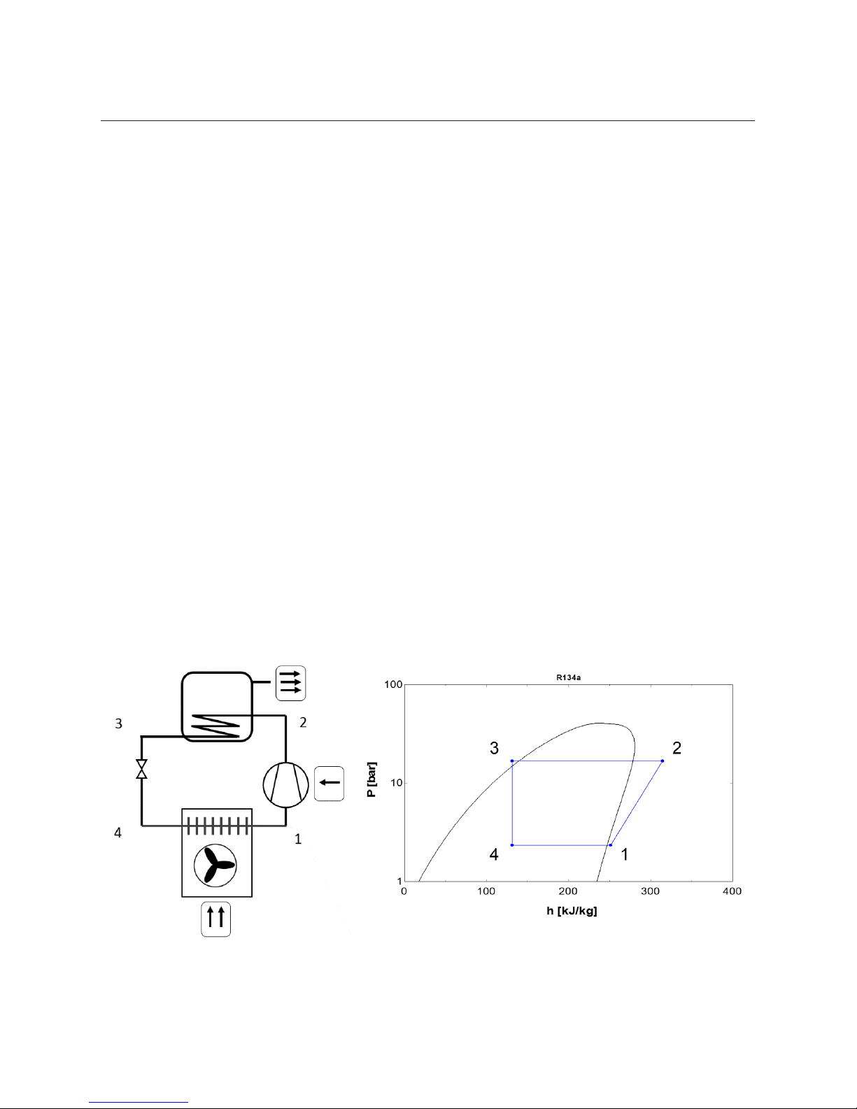
1.2.3. Cooling circuit
As depicted in Figure 1 and 2, the heat pump cycle can be divided in four main processes: compression (1-2), condensation (2-3), expansion (3-4), evaporation (4-1)
described below.
• At the suction of the compressor (1) the superheated gas refrigerant enters the
compressor at low pressure.
• In the compressor, the gas is compressed to a higher pressure and temperature
level (2).
• The gas is first de-superheated and condensed in the condenser, exchanging heat
with water stored in the tank.
• The refrigerant exits the condenser in a subcooled, liquid form (3)
• Through a thermostatic expansion valve the pressure of the refrigerant is lowered
to allow its evaporation at lower temperatures (4).
• The refrigerant is evaporated in the fin-coil heat exchanger that uses forced air as
heat source (1).
• The process goes on until the power supply to the compressor is stopped.
A deeper description of the cooling circuit and all components used for its design can
be found in Figure 3, 4 and 5.
3 2
14
Figure 1 – Heat pump principle Figure 2 – Pressure-Enthalpy diagram
7
Note: The extensive use of the electric heater leads to higher electricity consumption
and it may lead to high electricity bills. The operation with heat pump normally consumes more than 3 times less electricity than the operation with electric heater. The
energy released to the condenser (2-3) is, in fact, the sum between the free energy
extracted from the air in the evaporator (1-4) and the energy supplied to the compressor (2-1). On average, the energy absorbed by the evaporator is more than double of
the energy used to run the compressor.
1.2.4. Safety instructions – Cooling circuit
• Only skilled and trained technicians shall carry out repair and service of the heat
pump circuit.
• Before opening the cooling circuit, discharge the refrigerant to a level that allows
safe working conditions.
• The refrigerant can be toxic if inhaled or if in high concentrations.
• Special attention should be given if the work is carried out with an open flame.
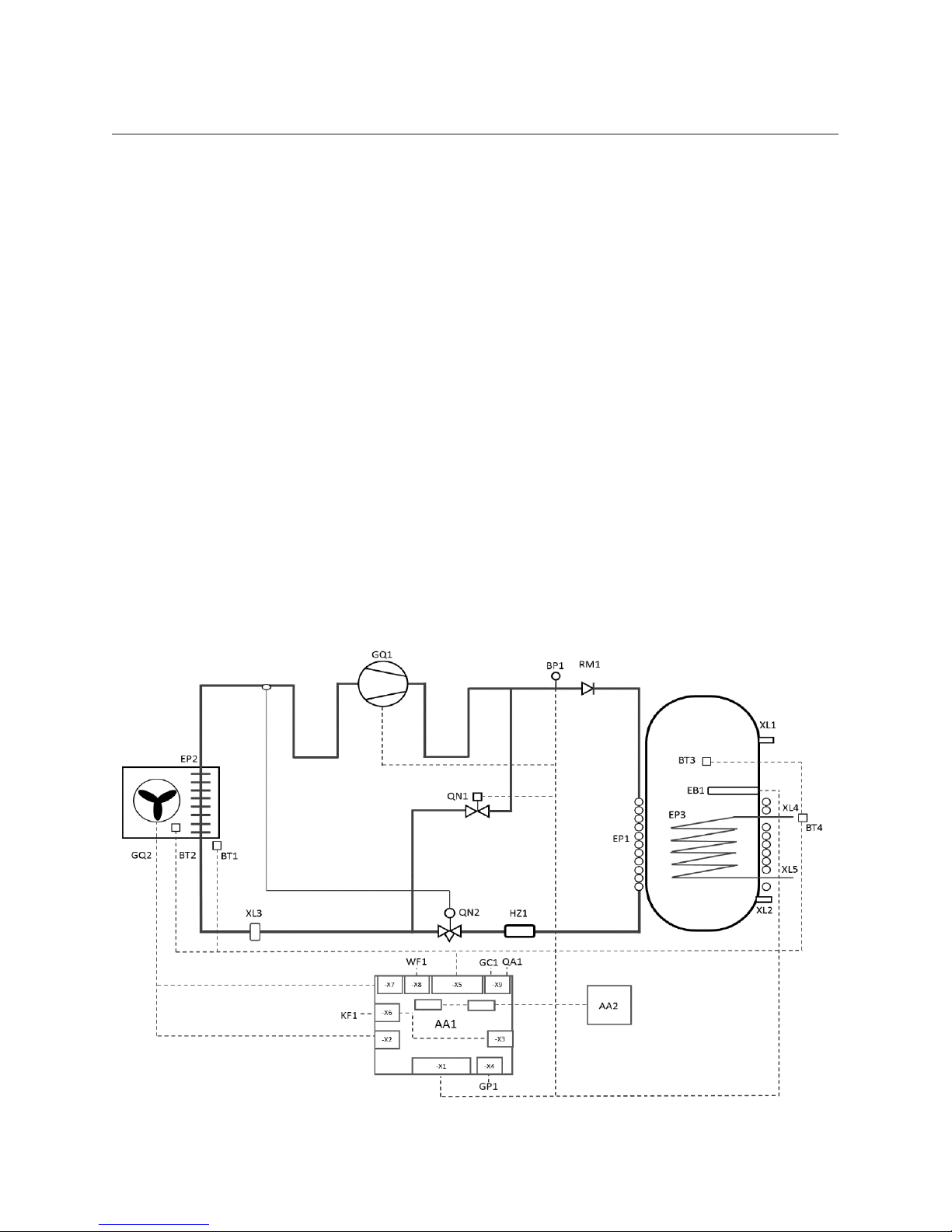
1.2.5. Process and Instrumentation Diagram
Figure 3 – Process and Instrumentation Diagram
8
AA1
XL7
XL6
GQ1
HZ1
RM1
CA1
GQ2
AA2
XL8
XL1
XL2
XL9
XL3
Refrigerant circuit
GQ1: Compressor
GQ2: Fan
RM1: Check valve
EP1: Condenser
EP2: Evaporator
HZ1: Filter drier
QN1: Solenoid valve
QN2: Thermostatic
expansion valve
XL3: Service valve
Water circuit
XL1: Water outlet
XL2: Water inlet
XL4*: Coil top
XL5*: Coil bottom
XL6: Air outlet
XL7: Air inlet
XL8: Condensate outlet
XL9*: Hot water circulation
EP3*: Coil
EB1: Electric heater
FR1: Anode
FN1: Thermal protection
The items with * are optional.
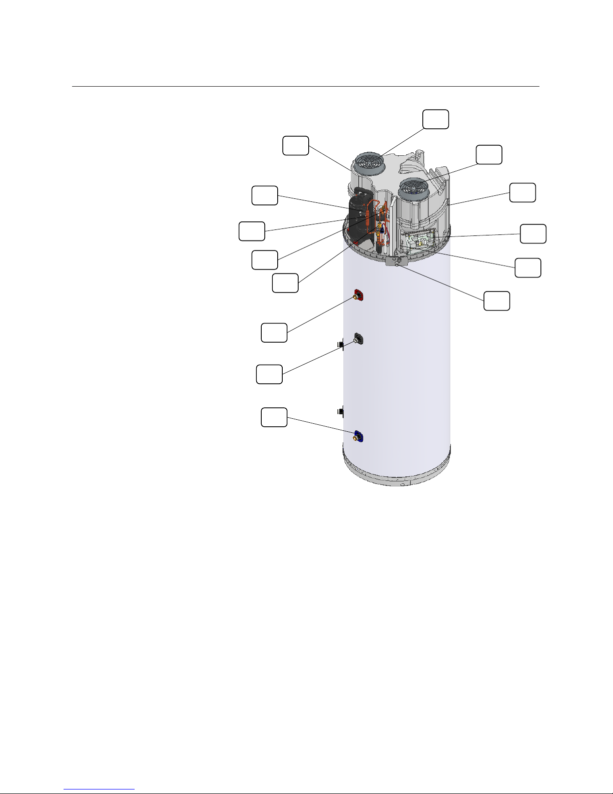
Figure 4 – Design of the cooling circuit and
the main components
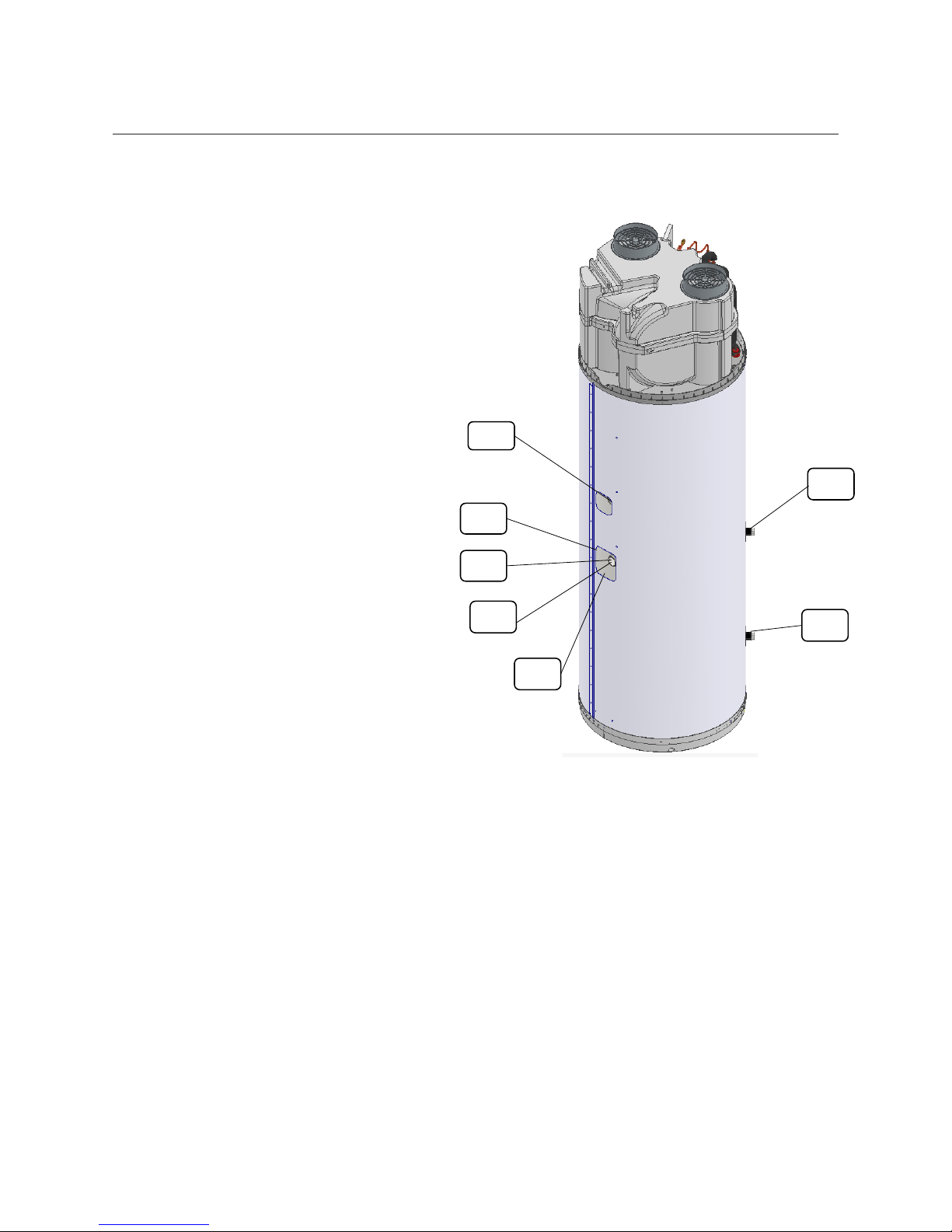
9
FR1
FN1
EB1
BT3
EP1
XL4
XL5
Sensors
BT1: Air inlet temperature
BT2: Evaporator temperature
BT3: Tank water temperature
BT4*: Additional temperature
BT5*: Additional temperature
(not included)
BP1: Pressostat
Electric components
AA1: Main printed circuit board
AA2: Display circuit board
WF1: Modbus port
GC1*: Solar 0-3V/10V
QA1*: SG-ready port
GP1*: Additional supply
to pump or damper
KF1*: Wi-Fi
The items with * are optional.
Nomenclature according to standard
IEC 81346-1 and 81346-2.
Figure 5 – Design of tank, condenser and
related components
10
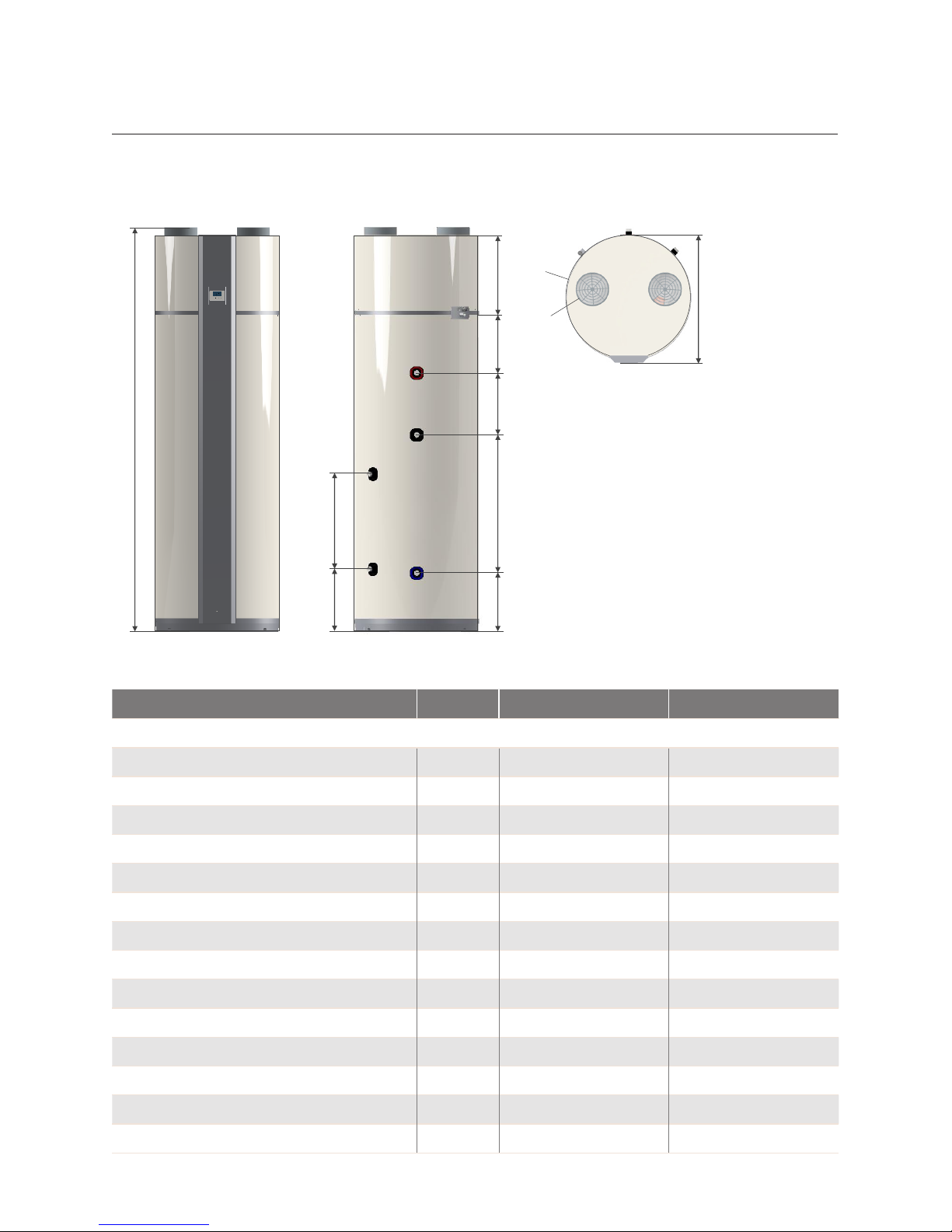
1.2.6. Main Technical Data
The main technical data are collected in the following figures and table.
A
B
C
H
F
G
D3
E2
D1
D2
E1
Figure 6 – Dimensional data
Parameter Unit 190L 260L
Dimensional data
A – Height mm 1610 1960
B mm 385 385
C mm 280 280
D1 mm 180 300
D2 mm 435 670
D3 mm 375 460
E1 mm 285 285
E2 mm 305 305
F – Diameter mm 603 603
G - Diameter mm 160 160
H – Max diameter mm 620 620
Height required for installation mm 1700 2040
Weight dry/wet (with coil) kg 94/284 (100/300) 100/350 (120/370)
Nominal insulation thickness mm 50 50
11
Parameter Unit 190L 260L
Electrical data
Power supply V/Hz 230/50
Fuse A 13 (10)
Electric connections - L1, N, G
Electric heater power W 1500
Cooling and water circuit
Refrigerant type - R134a
Refrigerant quantity g 1200 1280
GWP - 1430
CO2 equivalent ton 1,7 1,8
Cooling circuit - Hermetically sealed
Protection rating - IP21
Water connections - Enameled in ¾ - BSPT (ISO 7-1)
Water connections – Stainless* mm 22 – Compression fittings
Water condensate connection mm Ø19
Nominal insulation thickness mm 50 50
Corrosion protection - Magnesium anode / Stainless steel
Performance data
Outdoor air at 7°C (EN16147)
COP - 3.57 3.69
Heat up time hh:mm 06:28 09:12
Stand-by heat losses W 17 20
Sound power dB(A) 49 49
Indoor air at 20°C (EN16147)
COP - 4,13* 4.20
Heat up time hh:mm 05:15* 07:09
Stand-by heat losses W 17* 21
Sound power dB(A) 55.6 55.6
Volume at 40°C L 247 347
Paux W 1.61 1.61
*To be subjected to 3rd party test.
12
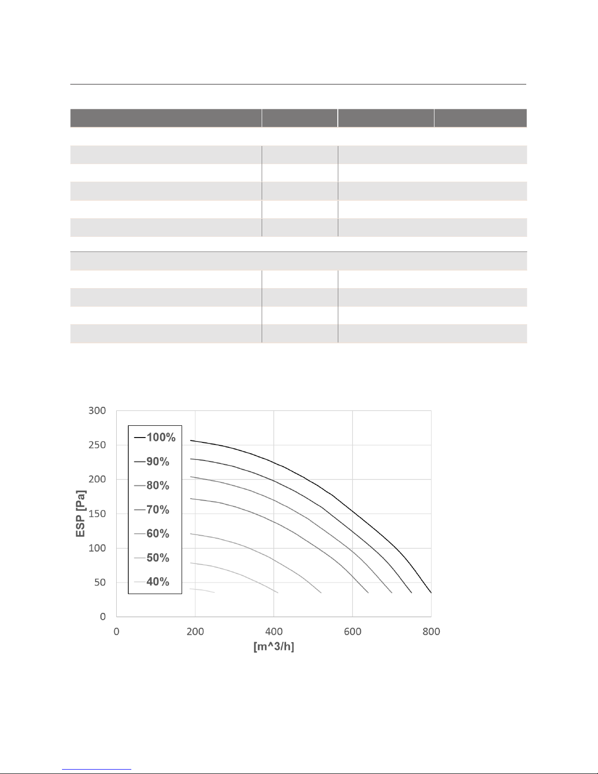
1.2.7. Fan Curve
Figure 7 – External static pressure vs airflow at different fan speeds.
In order to assure an efficient operation, it is suggested to keep the external pressure
drops below 200 Pa.
Parameter Unit 190L 260L
Airflow
Nominal air flow rate (variable range) m3/h 450 (0-800)
Maximum fan power consumption W 85
Max external static pressure Pa 200 Pa
G - Air duct connections mm 160
Minimum volume of room installation m
3
30
Operating limits
Max air temperature °C 40
Min air temperature °C -7
Max water temperature °C 60
Max water pressure MPa 0,6 or 1,0. Check nameplate

13
2. TRANSPORT, HANDLING AND DELIVERY
Immediately upon receipt, the domestic hot water heater pump must be examined to
make sure that it is intact and undamaged. If not, the shipping company must be
informed immediately. The recipient has the responsibility for all the shipments
unless otherwise agreed.
2.1. Delivery Mode
The appliance is delivered without condensate drain tube and the safety equipment
for the water circuit.
2.2. Storage
The unit must be stored and preferably transported upright, free of water and within
its packaging.
Transport and storage may take place at temperatures between -10 °C and +50 °C. If
the unit has been transported or stored at sub-zero temperatures the unit should be
left at room temperatures for 24 hours before commissioning.
2.3. Transport with Forklift
For transport with a forklift, the unit must stand on the associated transport frame.
Always lift the unit slowly. Due to the high center of gravity, the appliance must be
secured against tipping during transportation.
2.4. Unloading the Heat Pump
In order to avoid damages, the unit must be unloaded on a flat surface.
14
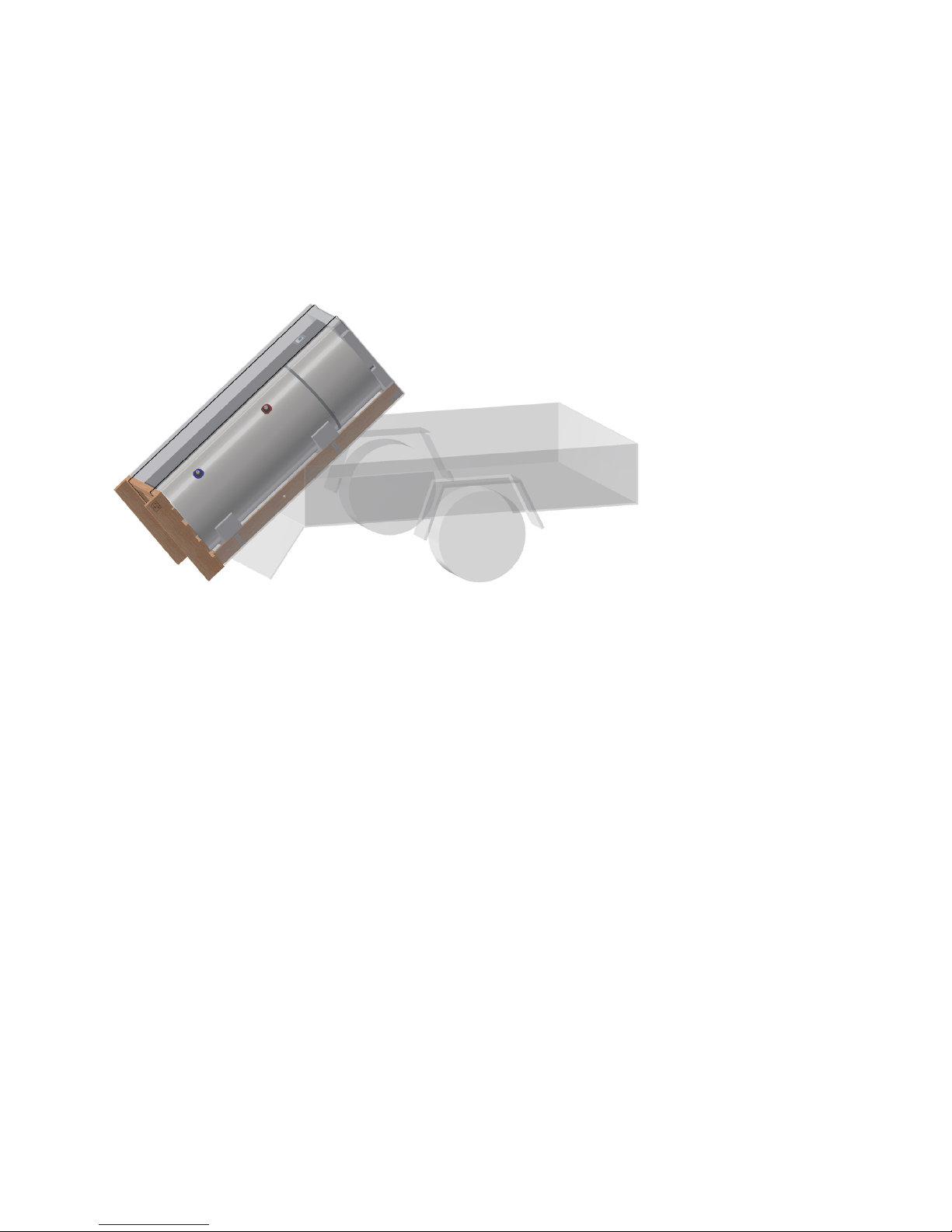
2.5. Transport with Trailer
The unit must only be transported on the associated transport frame. This also
applies to transport on stairs.
The unit must be secured against sliding on the trailer.
Water connections etc. shall not be used for transportation purposes.
It should be made sure that the trailer does not damage the cabinet or the
various connections.
Figure 8 - Transport with trailer
2.6 Horizontal transport
When carefully transporting the unit over a short distance to its final location, the unit
can be transported horizontally in its packaging on the dedicated side. If the unit has
been tilted more than 45°, the unit must be left in its normal upright position for at
least 24 hours before it is started.

15
3. POSITIONING
The installation site should be equipped with a power supply of 220-240V and 50 Hz.
The power supply and the hydraulic system must comply with the local regulations.
The unit should be placed vertically, with a maximum inclination of 1°. The unit must be
well balanced and stable on the ground surface. Use the built-in adjustable pads to
level the unit.
The unit must be installed as close as possible to the hydraulic system in order to minimize heat losses in the water pipes. The water pipe outlet should be insulated for the
same reason.
The unit should not be placed in direct contact with the sunlight.
The unit can only be installed in a frost-free room and it should follow the criteria:
• Room temperature between 5°C and 40°C.
• Drain possibility for condensate and floor drain.
• No abnormal dust concentration in the air.
• Solid base (approx. 500 kg / m2).
• It is necessary to ensure that there is sufficient space around the unit for mainte-
nance and service. A clearance of 0.5 m around the unit is recommended.
Ducted unit
In case of a ducted unit, the unit should be
installed as close as possible to the walls in order
to minimize pressure losses in the air ducts.
Not-ducted unit
In case the unit is used without exhaust/extraction air ducts, it should be placed in a room with
the following characteristics:
• The volume of the room should be more than
30 m3.
• The room should be well ventilated.
• There should be no other appliances that need
air to operate.
• The minimum distances described in Figure 9
should be respected.
Figure 9 - Minimum distance from
walls for not-ducted units
16
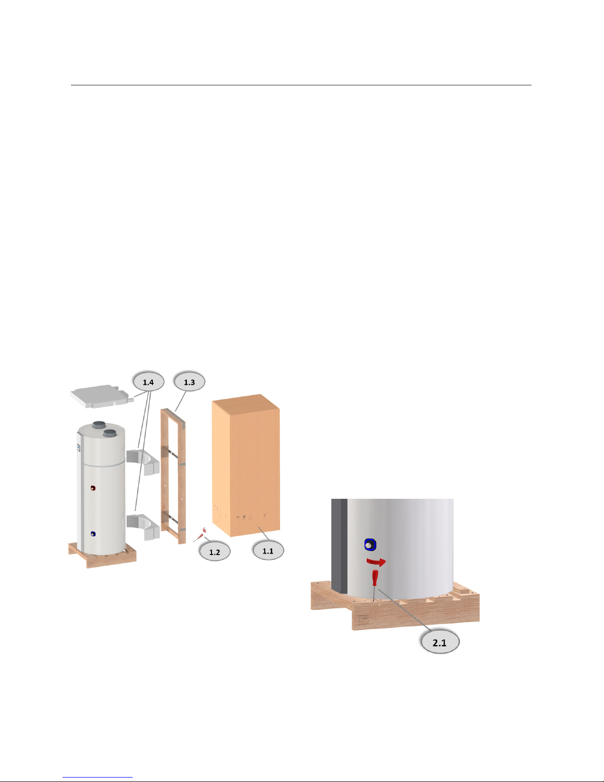
3.1. Set-up sequence
Once the unit is placed in a room with characteristics as specified in the previous
paragraph, then it can be prepared following the sequence described below:
1. Remove the packaging from the pallet.
2. Remove the transport fittings from the pallet.
3. Remove the unit off the pallet and place it on the floor.
4. Adjust the unit vertically by adjusting the feet.
5. Check that the unit has no damages.
6. Set-up the water circuit (See chapter 4) and fill the tank with water.
7. Set-up the air circuit (See chapter 5).
8. Set-up the electric connections (See chapter 6).
When the unit is supplied with electricity, it automatically starts running in its
standard operation according to the factory settings as described in Chapter 7.
Figure 10 - Set-up sequence
 Loading...