


Metronix Meßgeräte und Elektronik GmbH Telefon: +49-(0)531-8668-0
Kocherstraße 3 Telefax: +49-(0)531-8668-555
38120 Braunschweig E-mail: vertrieb@metronix.de
Germany http://www.metronix.de
Servo Positioning Controller ARS
2302 FS, 2305 FS and 2310 FS
designed for Functional Safety
Mounting Instructions
Version 9.0
1 General
1.1 Documentation
This installation information serves the purpose of a safe use of the ARS 2300 FS series servo
positioning controller. It contains safety notes, which must be complied with.
Further information can be found in the following manuals of the ARS 2000 FS product range:
Product Manual “Servo Positioning Controller ARS 2300 FS”: Description of the technical
specifications and the device functionality as well as notes on the installation and the operation of
the servo positioning controller ARS 2302 FS, 2305 FS and 2310 FS.
Software Manual “Servo Positioning Controller ARS 2000”: Description of the software and
firmware functions usable with the parameterisation program Metronix ServoCommander
®
.
CANopen Manual “Servo Positioning Controller ARS 2000“: Description of the implemented
CANopen protocol as per DSP402.
PROFIBUS Manual “Servo Positioning Controller ARS 2000”: Description of the implemented
PROFIBUS-DP protocol.
Sercos Manual “Servo Positioning Controller ARS 2000”: Description of the implemented
Sercos II protocol.
EtherCAT Manual “Servo Positioning Controller ARS 2000”: Description of the implemented
EtherCAT (CoE – CANopen over EtherCAT) protocol.
Product Manual “FSM 2.0 – STO”: Description of the technical specifications and the device
functionality.
Product Manual “FSM 2.0 – MOV”: Description of the technical specifications and the device
functionality (German version).
You can find all these documents on our homepage at the download area (http://www.metronix.de/).

Safety notes for electrical drives and controllers Page 2
2 Safety notes for electrical drives
and controllers
2.1 Used symbols
Information
Important information and notes.
Caution!
Nonobservance may result in severe property damages.
DANGER!
Nonobservance may result in property damages and in personal injuries.
Caution! Dangerous voltages.
The safety note indicates a possible perilous voltage.
2.2 General notes
In case of damage resulting from non-compliance with the safety notes in this manual, Metronix
Meßgeräte und Elektronik GmbH will not assume any liability.
Sound and safe operation of the servo drive controller requires proper and professional transportation,
storage, assembly and installation as well as proper operation and maintenance. Only trained and
qualified personnel may handle electrical devices:
TRAINED AND QUALIFIED PERSONNEL
in the sense of this product manual or the safety notes on the product itself are persons who are
involved in the project planning, the setup, assembly, commissioning and operation of the product as
well as all warnings and precautions as per the instructions in this manual and who are sufficiently
qualified in their field of expertise:
Education and instruction of standard specifications and accident prevention regulations, which
are necessessary in the application, and authorisation to switch devices/systems on and off and to
ground them as per the standards of safety engineering and to efficiently label them as per t he j ob
demands.
Education and instruction as per the standards of safety engineering regarding the maintenance
and use of adequate safety equipment.
Training in first aid.
The following notes must be read prior to the initial operation of the system to prevent personal
injuries and/or property damages:

Safety notes for electrical drives and controllers Page 3
These safety notes must be complied with at all times.
Do not try to install or commission the servo drive controller before carefully reading all safety
notes for electrical drives and controllers contained in this document. These safety
instructions and all other user notes must be read prior to any work with the servo drive
controller.
In case you do not have any user notes for the servo drive controller, please contact your
sales representative. Immediately demand these documents to be sent to the person
responsible for the safe operation of the servo drive controller.
If you sell, rent and/or otherwise make this device available to others, these safety notes
must also be included.
The user must not open the servo drive controller for safety and warranty reasons.
Professional control process design is a prerequisite for sound functioning of the servo drive
controller!
DANGER!
Inappropriate handling of the servo drive controller and non-compliance of the
warnings as well as inappropriate intervention in the safety features may result in
property damage, personal injuries, electri c sh ock or in extreme cases even death.
2.3 Danger resulting from misuse
DANGER!
High electrical voltages and high load currents!
Danger to life or serious personal injury from electrical shock!
DANGER!
High electrical voltage caused by wrong connections!
Danger to life or serious personal injury from electrical shock!
DANGER!
Surfaces of device housing may be hot!
Risk of injury! Risk of burning!
DANGER!
Dangerous movements!
Danger to life, serious personal injury or property damage due to unintentional
movements of the motors!

Safety notes for electrical drives and controllers Page 4
2.4 Safety notes
2.4.1 General safety notes
The servo positioning controller corresponds to IP20 degree of protection as well as pollution
degree 2. Make sure that the environment corresponds to this degree of protection and
pollution degree.
Only use replacements parts and accessories approved by the manufacturer.
The devices must be connected to the mains supply as per EN regulations, so that they can
be cut off the mains supply by means of corresponding separation devices (e.g. main switch,
contactor, power switch).
The servo drive controller may be protected using an AC/DC sensitive 300mA fault current
protection switch, type B (RCD = Residual Current protective Device).
Gold contacts or contacts with a high contact pressure should be used to switch the control
contacts.
As a precaution screening measures for switchgears must be met, as e.g. contactors and
relays with RC elements and/or diodes wire.
The safety rules and regulations of the country in which the device will be operated must be
complied with.
The environment conditions defined in the product documentation must be kept. Safetycritical applications are not allowed, unless specifically approved by the manufacturer.
The compliance with the limits required by national regulations is the responsibility of the
manufacturer of the machine or system.
The technical data and the connection and installation conditions for the servo drive controller
are to be found in this product manual and must be met.
DANGER!
The general setup and safety regulations for work on power installations (e.g. DIN, VDE,
EN, IEC or other national and international regulations) must be complied with.
Non-compliance may result in death, personal injury or serious property damages.
Without claiming completeness, the following regulations and others apply:
VDE 0100 Erection of power installations with nominal voltages up to 1000 V
EN 1037 Safety of maschinery - Prevention of unexpected start-up
EN 60204-1 Safety of machinery - Electrical equipment of machines
Part 1: General requirements
EN 61800-3 Adjustable speed electrical power drive systems
Part 3: EMC requirements and specific test methods
EN 61800-5-1 Adjustable speed electrical power drive systems
Part 5-1: Safety requirements - Electrical, thermal and energy

Safety notes for electrical drives and controllers Page 5
EN 61800-5-2 Adjustable speed electrical power drive systems
Part 5-2: Safety requirements - Functional
EN ISO 12100 Safety of machinery - General principles for design - Risk assessment and
risk reduction
EN ISO 13849-1 Safet y of machinery - Safety-related parts of control systems
Part 1: General principles for design
EN ISO 13849-2 Safet y of machinery - Safety-related parts of control systems
Part 2: Validation
More standards to be respected by the user:
EN 574 Safety of machinery - Two-hand control devices
EN 1088 Safety of machinery - Interlocking devices associated with guards
EN 1037 Safety of maschinery - Prevention of unexpected start-up
EN ISO 13850 Safety of machinery - Emergency stop
2.4.2 Safety notes for assembly and maintenance
The appropriate DIN, VDE, EN and IEC regulations as well as all national and local safety regulations
and rules for the prevention of accidents apply for the assembly and maintenance of the system. The
plant engineer or the operator is responsible for compliance with these regulations:
The servo drive controller must only be operated, maintained and/or repaired by personnel
trained and qualified for working on or with electrical devices.
Prevention of accidents, injuries and/or damages:
Additionally secure vertical axes against falling down or lowering after the motor has been
switched off, e.g. by means of:
Mechanical locking of the vertical axle
External braking, catching or clamping devices or
Sufficient balancing of the axle
The motor holding brake supplied by default or an external motor holding brake driven by the
drive controller alone is not suitable for personal protection!
Keep the electrical equipment voltage-free using the main switch and protect it from being
switched on again until the DC bus circuit is discharged, in the case of:
Maintenance and repair work
Cleaning
long machine shutdowns
Prior to carrying out maintenance work make sure that the power supply has been turned off,
locked and the DC bus circuit is discharged.
The external or internal brake resistor carries dangerous DC bus voltages during operation of
the servo drive controller and up to 5 minutes thereafter. Contact may result in death or
serious personal injury.

Safety notes for electrical drives and controllers Page 6
Be careful during the assembly. During the assembly and also later during operation of the
drive, make sure to prevent drill chips, metal dust or assembly parts (screws, nuts, cable
sections) from falling into the device.
Also make sure that the external power supply of the controller (24V) is switched off.
The DC bus circuit or the mains supply must always be switched off prior to switching off the
24V controller supply.
Carry out work in the machine area only, if AC and/or DC supplies are switched off. Switched
off output stages or controller enablings are no suitable means of locking. In the case of a
malfunction the drive may accidentally be put into action, except driv es with active safety
function “Safe Torque Off”.
Motor set up, automatic tuning and identification procedures must be done with free-wheeling
motor to prevent mechanical damage due to unexpected motor movement.
Electronic devices are never fail-safe. It is the user’s responsibility, in the case an electrical
device fails, to make sure the system is transferred into a secure state.
The servo drive controller and in particular the brake resistor, externally or internally, can
assume high temperatures, which may cause serious burns.
2.4.3 Protection against contact with electrical part s
This section only concerns devices and drive components carrying voltages exceeding 50 V. Contact
with parts carrying voltages of more than 50 V can be dangerous for people and may cause electrical
shock. During operation of electrical devices some parts of these devices will inevitably carry
dangerous voltages.
DANGER!
High electrical voltage!
Danger to life, danger due to electrical shock or serious personal injury!
The appropriate DIN, VDE, EN and IEC regulations as well as all national and local safety regulations
and rules for the prevention of accidents apply for the assembly and maintenance of the system. T he
plant engineer or the operator is responsible for compliance with these regulations:
Before switching on the device, install the appropriate covers and protections against
accidental contact. Rack-mounted devices must be protected against accidental contact by
means of a housing, e.g. a switch cabinet. The regulations VGB4 must be complied with!
Always connect the ground conductor of the electrical equipment and devices securely to the
mains supply. Due to the integrated line filter the leakage current exceeds 3.5 mA!
Comply with the minimum copper cross-section for the ground conductor over its entire
length as per EN 60617!
Prior to the initial operation, even for short measuring or testing purposes, always connect the
ground conductor of all electrical devices as per the terminal diagram or connect it to the
ground wire. Otherwise the housing may carry high voltages which can cause electrical
shock.

Safety notes for electrical drives and controllers Page 7
Do not touch electrical connections of the components when switched on.
Prior to accessing electrical parts carrying voltages exceeding 50 Volts, disconnect the
device from the mains or power supply. Protect it from being switched on again.
For the installation the amount of DC bus voltage must be considered, particularly regarding
insulation and protective measures. Ensure proper grounding, wire dimensioning and
corresponding short-circuit protection.
The device comprises a rapid discharge circuit for the DC bus as per EN60204 section 6.2.4.
In certain device constellations, however, mostly in the case of parallel connection of several
servo drive controllers in the DC bus or in the case of an unconnected brake resistor, this
rapid discharge may be ineffective. The servo drive controllers can carry voltage until up to 5
minutes after being switched off (residual capacitor charge).
2.4.4 Protection against electrical shock by means of protective extra-low
voltage (PELV)
All connections and terminals with voltages of up to 50 Volts at the servo drive controller are protective
extra-low voltage, which are designed safe from contact in correspondence with the following
standards:
International: IEC 60364-4-41.
European countries within the EU: EN 50178/1998, section 5.2.8.1.
DANGER!
High electrical voltages due to wrong connections!
Danger to life, risk of injury due to electrical shock!
Only devices and electrical components and wires with a protective extra low voltage (PELV) may be
connected to connectors and terminals with voltages between 0 to 50 Volts.
Only connect voltages and circuits with protection against dangerous voltages. Such protection may
be achieved by means of isolation transformers, safe optocouplers or battery operation.
The signals for the temperature sensor "MT-" (PIN 4) and "MT+" (PIN 5) on the motor
connector plug [X6] are not situated on safety extra-low voltage
(PELV - protective extra-low voltage). The connections are designed for non-PELV
temperature sensors. The isolation to PELV is part inside the ARS 2000 FS.

Safety notes for electrical drives and controllers Page 8
2.4.5 Protection against dangerous movements
Dangerous movements can be caused by faulty control of connected motors, for different reasons:
Improper or faulty wiring or cabling.
Error in handling of components.
Error in sensor or transducer.
Defective or non-EMC-compliant components.
Software error in superordinated control system
These errors can occur directly after switching on the device or after an indeterminate time of
operation.
The monitors in the drive components for the most part rule out malfunctions in the connected drives.
In view of personal protection, particularly the danger of personal injury and/or property damage, thi s
may not be relied on exclusively. Until the built-in monitors come into effect , faulty drive movements
must be taken into account; their magnitude depends on the type of control and on the operating
state.
DANGER!
Dangerous movements!
Danger to life, risk of injury, serious personal injuries or property damage!
For the reasons mentioned above, personal protection must be ensured by means of monitoring or
superordinated measures on the device. These are installed in accordance with the specific data of
the system and a danger and error analysis by the manufacturer. The safety regulations applying to
the system are also taken into consideration. Random movements or other malfunctions may be
caused by switching the safety installations off, by bypassing them or by not act i vating them.
2.4.6 Protection during handling and assembly
Handling and assembly of certain parts and components in an unsuitable manner may under adverse
conditions cause injuries.
DANGER!
Risk of injury due to improper handling!
Personal injury due to pinching, shearing, cutting, crushing!
The following general safety notes apply:
Comply with the general setup and safety regulations on handling and assembly.
Use suitable assembly and transportation devices.
Prevent incarcerations and contusions by means of suitable protective measures.

Safety notes for electrical drives and controllers Page 9
Use suitable tools only. If specified, use special tools.
Use lifting devices and tools appropriately.
If necessary, use suitable protective equipment (e.g. goggles, protective footwear, prot ect i ve
gloves).
Do not stand underneath hanging loads.
Remove leaking liquids on the floor immediately to prevent slipping.
2.4.7 Protection against contact with hot parts
DANGER!
Housing surfaces may be hot!
Risk of injury! Risk of burning!
Do not touch housing surfaces in the vicinity of heat sources! Danger of burning!
Before accessing devices let them cool down for 10 minutes after switching them off.
Touching hot parts of the equipment such as the housing, which contain heat sinks and
resistors, may cause burns!

Technical data Page 10
3 Technical data
Range ARS 2302 FS ARS 2305 FS ARS 2310 FS
Metronix part number
with FBA module
9200-2302-20 9200-2305-20 9200-2310-20
Metronix part number
with STO module
9200-2302-22 9200-2305-22 9200-2310-22
Metronix part number
with MOV module
9200-2302-23 9200-2305-23 9200-2310-23
Power connector set 9200-0230-20
Signal connector set 9200-0200-00
FBA module 9200-0150-00
STO module 9200-0151-00
MOV module 9200-0152-00
Ambient conditions and qualification:
Admissible temperature ranges Storage temperature: -25°C to +70°C
Operating temperature: 0°C to +40°C
+40°C to +50°C at reduced power 2,5%/K
Admissible installation height Mounting height maximum 2000 m above msl, above 1000 m
above msl with power reduction 1% per 100 m
Humidity Relative humidity up to 90%, not bedewing
Protection degree
IP20
Protection class
I
Pollution degree
2
CE conformity
Low-voltage directive:
EMC directive:
2006/95/EC
verified by application of the harmonised standard EN 61800-5-1
2004/108/EC
verified by application of the harmonised standard EN 61800–3
cULus certification Listed according to UL 508C, C22.2 No. 274-13
Dimensions and weight:
Dimensions: H*W*D 334,5 x 69 x 245,5 mm
Weight c. 3,7 kg
Performance data [X9]:
Supply voltage 3 x 230 ... 480 VAC [+/- 10%], 50…60 Hz
Alternative DC supply 60 ... 700 VDC

Technical data Page 11
Range ARS 2302 FS ARS 2305 FS ARS 2310 FS
24V supply
*) plus current consumption of a
possibly connected holding brake
and I/Os
24 VDC [± 20%] (1 A) *)
Internal brake resistor [X9]:
Brake resistance 68 Ω
Pulse power 8,5 KW
Continuous power 110 W
Threshold limit 760 V
External brake resistor [X9]:
Brake resistance external ≥ 40 Ω
Continuous power ≤ 5000 W
Permissible operating voltage ≥ 800 V
Motor connection specifications [X6]:
Specifications for operation with 3x 400 VAC [± 10%], 50 Hz, with an output stage clock frequency of 5 kHz
Output power 1,5 kVA 3 kVA 6 kVA
Max. output power for 3 s 3 kVA 6 kVA 12 kVA
Output current 2,5 A
RMS
5 A
RMS
10 A
RMS
Max. output current for 0.5 s and
f
s
> 5Hz
Max. output current for 3 s
10 A
RMS
7.5 A
RMS
20 A
RMS
10 A
RMS
40 A
RMS
(for 0,3s)
20 A
RMS
Max. mains current for continuous
operation
2,5 A
RMS
5 A
RMS
9 A
RMS
Output stage clock frequency 4…16 kHz (software programmable)
As a guideline: Power
loss/efficiency (with regard to the
rated output power)
typical 8% / 92%
Maximum motor cable length for interference emission as per EN 6180 0-3:
Category C2 (ex first ambient with
limited availability)
Switch cabinet assembly
l ≤ 50m
Category C3 (ex second ambient)
(industrial area)
l ≤ 50m
Cable capacity of a phase against
shield or between two lines
C‘ ≤ 200pF/m
Motor temperature monitoring:
Digital sensor
These contacts have a PELV
(Protective extra-low voltage).
Normally closed contact: R
cold
< 500 Ω R
hot
> 100 kΩ

Technical data Page 12
Range ARS 2302 FS ARS 2305 FS ARS 2310 FS
Analog sensor Silicon temperature sensor, e.g. KTY81, 82 or similar
R25 ≈ 2000 Ω R
100
≈ 3400 Ω
Resolver [X2A]:
Resolution 16 Bit
Delay time signal detection < 200 µs
Speed resolution ca. 4 min-1
Absolute accuracy of angle
detection
< 5´
Max. rotational speed 16.000 min-1
Encoder evaluation [X2B]:
Parameterisable number of encoder
lines
1 – 218 lines/rev
Angular resolution / Interpolation 10 Bit / period
Encoder signals A, B 1 VPP differential; 2.5 V offset
Encoder signal N 0.2 to 1 VPP differential; 2.5 V offset
Commutation track A1, B1
(optional)
1 VPP differential; 2.5 V offset
Input impedance encoder signals Differential input 120 Ω
Limit frequency f
Limit
> 300 kHz (high-res. signal)
f
Limit
ca. 10 kHz (commutation track)
Additional communication interface
EnDat (Heidenhain) and HIPERFACE (Stegmann)
Output supply 5 V or 12 V; max. 300 mA; currentlimited control via sensor lines
Setpoint programmable via software
Digital inputs and outputs [X1]:
Signal level 24V (8V...30V) active high, conforming with DIN EN 61131-2
Logic inputs general
DIN0
DIN1
DIN2
DIN3
Bit 0 \
Bit 1, \ Target selection for positioning
Bit 2, / 16 targets selectable from target table
Bit 3 /
DIN4 Control input stage enable at High
DIN5 Controller enable at High, clear error high-low transition at Low
DIN6 End switch input 0
DIN7 End switch input 1
DIN8 Control signal Start positioning
DIN9 Home switch for homing or saving of positions
Logic outputs general Galvanically separated, 24V (8V...30V) active high

Technical data Page 13
Range ARS 2302 FS ARS 2305 FS ARS 2310 FS
DOUT0 Operational state 24 V, max. 100 mA
DOUT1 Freely configurable 24 V, max. 100 mA
DOUT2 Freely configurable, optional use
as input DIN10
24 V, max. 100 mA
DOUT3 Freely configurable, optional use
as input DIN11
24 V, max. 100 mA
DOUT4 [X6] Holding brake 24 V, max. 2 A
Analog inputs and outputs [X1]:
High-resolution analog input:
AIN0
±10V input range, 16 Bit, differentially,
< 250µs delay time
Analog input:
AIN1
Optionally, this input can also be
parameterized as digital input
DIN AIN1 with a switching
threshold at 8V.
±10V, 10 Bit, single ended,
< 250µs delay time
Analog input:
AIN2
Optionally, this input can also be
parameterized as digital input
DIN AIN2 with a switching
threshold at 8V.
±10V, 10 Bit, single ended,
< 250µs delay time
Analog outputs:
AOUT0 and AOUT1
±10V output range, 9 bit resolution, f
Limit
> 1kHz
Incremental encoder input [X10]:
Parameterisable number of encoder
lines
1 – 228 lines/rev
Trace signals As per RS422 specification
Max. input frequency 1000 kHz
Pulse-direction interface As per RS422 specification
Output supply 5 V, max. 100 mA
Incremental encoder output [X11]:
Number of lines Programmable 1 – 213 and 214 lines/revolution
Connection level Differential / RS422 specification
Encoder signals A, B, N As per RS422 specification
speciality N-Trace disconnectible
Output impedance R
a,diff
= 66 Ω
Limit frequency f
Limit
> 1,8 MHz (lines/s)
Edge triggering
(minimum pulse width)
Can be limited by parameters
Output supply 5 V, max. 100 mA
Ethernet [X18]:
RJ45, 10/100 MBaud (auto select)
USB [X19]:
According to USB 2.0, USB-B, slave-client
SD card slot
SD, SDHC and MMC - FAT12, FAT16 and FAT32

Technical data Page 14
3.1 Supported motor feedback systems
Listing of supported motor feedback systems, valid from april 2009
Type Notes Protocol
Heidenhain EnDat encoder:
ROC 400
ECI 1100/1300
ECN 100/400/1100/1300
Single-turn absolute encoder with or without analog
signal.
EnDat 2.1 (01/21)
EnDat 2.2 (22)
ROQ 400
EQI 1100/1300
EQN 100/400/1100/1300
Multi-turn absolute encoder with or without analog
signal.
EnDat 2.1 (01/21)
EnDat 2.2 (22)
LC 100 / 400 Absolute linear encoders .
EnDat 2.1 (01)
EnDat 2.2 (22)
Stegmann HIPERFACE® Encoder:
SCS60/70
SCM60/70
Single- / multi-turn encoder with analog incremental
signal. Line count 512 (fix).
Number of multi-turn revolutions: +/- 2048 U.
HIPERFACE®
SRS50/60/64
SCKxx
SRM50/60/64
SCLxx
Single- / multi-turn encoder with analog incremental
signal. Line count 1024 (fix).
Number of multi-turn revolutions: +/- 2048 U
xx = 25 / 35 / 40 / 45 / 50 / 53
HIPERFACE®
SKS36
SKM36
Single- / multi-turn encoder with analog incremental
signal. Line count 128 (fix).
Number of multi-turn revolutions: +/- 2048 U
HIPERFACE®
SEK37/52
SEL37/52
Single- / multi-turn encoder with analog incremental
signal. Line count 16 (fix).
Number of multi-turn revolutions: +/- 2048 U
HIPERFACE®
L230
Absolute length measuring system with analog
incremental signal. Resolution: 156,25 µm.
Measuring length max. ca. 40 m.
HIPERFACE®
Yaskawa Σ-Encoder:
Σ (sigma 1) Digital incremental encoder with zero-pulse
Yaskawa-OEMprotocol
Analog incremental encoder:
ROD 400
ERO 1200/1300/1400
ERN 100/400/1100/1300
Heidenhain, encoder with zero- and reference pulse
Digital incremental encoder:
CDD50 Stegmann, encoder with hall sensors
Resolver:
Standard
transmission ratio typ. 0,5 +- 10 %,
Input supply typ. 7 Vrms

Mechanical installation Page 15
4 Mechanical installation
4.1 Important notes
Only use the servo positioning controller ARS 2300 FS as a built-in device for switch cabinets.
Mounting position vertical with supply lines
[X9] on top.
Mount to control cabinet plate using a fastening strap.
Installation spaces: Keep a minimum distance of 100 mm to other components each above and
underneath the device to ensure sufficient venting.
The servo positioning controller ARS 2300 FS may be installed adjacently in one switch cabinet
without a gap, proper usage and installation on a heat-dissipating rear panel provided. Please
note that excessive heat may cause premature aging and/or damaging of the device. In case the
servo positioning controller ARS 2300 FS are subject to high thermal stress, a space of 75 mm is
recommended!
The connections of the following illustrations for the servo positioning controller
ARS 2302 FS also apply to the servo positioning controller ARS 2305 FS and
ARS 2310 FS!

Mechanical installation Page 16
100 mm
100 mm installation free space for a sufficient
ventilation of the servo positioning controllers
ARS 2302 FS, ARS 2305 FS and ARS 2310 FS
100 mm installation free space for a sufficient
ventilation of the servo positioning controllers
ARS 2302 FS, ARS 2305 FS and ARS 2310 FS
100 mm
Status display
[X19] USB communication
Connection for
- [X4] CANopen interface
- [X5] serial tnterface RS232
RESET button
LED status
- READY / ERROR
- ENABLE
- CAN ON
[X18] Ethernet communication
Terminating resistor for
CANopen
Technology slots
TECH1 and TECH2 for
- MC 2000
- SERCOS II
- PROFIBUS-DP
- EtherCAT
- EA88
- service modul
Assembly mounting plate
Connection for the shield
- motor cable
- encoder cable
SD-Card slot
Boot action
FSM2.0 FBA with DIP switch to
set the slave address
FSM
STATE[X
19]USB[
X8]ETH
ERNET
[X
4]C AN
[X5]RS2
32/ RS48
5
[X4
]
[X5
]
CAN
TERM
SD
-/MMC-C
ARD
BOO
T
TECH
1
TECH
2
READ
Y/
ERRO
R
ENABL
E
CAN ON
RES
ET
OFF ON O
FFON
FIEL
DBU
SPA
RAM
ETER
0 1 2 3 4 5 76ON
FS
M
STATE[X19]USB[X8] ETHERNET
[X4]CAN
[X5]RS232/ RS485
[X4
]
[X5
]
CANTERM
SD-/MMC-CARD
BOOT
TECH
1
TECH
2
READ
Y/
ERRO
R
ENABL
E
CAN ON
RES
ET
OFF ON OFFON
FIELDBUSPARAMETER
0 1 2 3 4 5 76ON
(OPTIONAL)
[X40] FSM2.0-STO Safety
module SIL3 CL3 acc.
EN61800-5-2, EN62061/Cat.4
PLe acc. EN ISO 13849-1
FSM 2.0-STO
SIL3 SILCL3 acc.
EN61800-5-2,
EN62061/Cat.4
PLe acc.
EN ISO 13849-1
STATE
[X40] SAFE TORQUE OFF
STO_B
0V
24V
C1
C2
0V_B
0V_A
STO_A
1 2
3 4 5
6 87
ON
Fieldbus Parameter
ON
ARS2310 FS
ARS2310 FS
Figure 1: Servo positioning controller ARS 2310 FS: Front view and Installation space

Mechanical installation Page 17
[X11]: Incremental encoder output
[X10]: Incremental encoder input
[X1]: I/O interface
[X1] I/O[X10] IN[X11] OUT
[X9.]
PEBR-INTBR-CH
BR-EXT
ZK-ZK+L3L2L1
+24V GND24V
Power Supply [X9]:
L 1: mai ns phase 480VAC
L 2: mai ns phase 480VAC
L 3: mai ns phase 480VAC
ZK+: pos. DC bus vol tage
ZK-: neg. DC bus voltage
BR-EXT: extern brake chopper
BR-CH: brake chopper
BR-INT: intern brake chopper
PE: ground conductor from
mains
+24V: 24VDC
GND24V: GND 24VDC
Figure 2: Servo positioning controller ARS 2302 FS: Top view
Motor Connection [X6]:
BR-: holding brake
BR+:
holding brake
PE: inner shield
MT-:
motor sensor
MT+ motor sensor
PE:
motor ground conductor
W: motor phase 3
V: motor phase 2
U: motor phase 1
[X2A]: Connection for the resolver
[X2B]: Connection for the encoder
[X6.]
[X2A] RESOLVER
[X2B] ENCODER
UVWPEMT+MT-PEBR+BR-
Connection for the shield
Figure 3: Servo positioning controller ARS 2302 FS: Bottom view

Mechanical installation Page 18
4.2 Mounting
The servo positioning controller ARS 2300 FS has attachment lugs on the top and the bottom of the
device. These are used to mount the servo positioning controller vertically to a control cabinet plat e.
The lugs are part of the cooling body profile, thereby providing optimum heat transmission t o the
control cabinet plate.
Please use M5 screws for the mounting of the servo positioning controller ARS 2302 FS,
ARS 2305 FS and ARS 2310 FS.
R5
R2,6
R2,6
M4 flush head stud
M4 flush head stud
R2,5
5 mm
24 mm
31,75 mm
39,5 mm
58,5 mm
63,5 mm
69 mm
9 mm
12 mm
15 mm
21 mm
28,9 mm
320,8 mm
328,9 mm
334,5 mm
ca. 1 mm
Figure 4: Servo positioning controller ARS 2302 FS, ARS 2305 FS and ARS 2310 FS:
Mounting plate

Electrical installation Page 19
5 Electrical installation
Caution!
Operation with DC bus coupling together with devices of the ARS 2100 FS series is not
allowed.
5.1 Pin configuration I/O [X1]
Pin No. Denomination Value Specification
1 AGND 0V Shield for analog signals, AGND
14 AGND 0V Reference potential for analog signals
2 AIN0 Uon = ±10V
R
I
≥30kΩ
Setpoint input 0, differential, max. 30V input
voltage
15 #AIN0
3 AIN1 Uon = ±10V
R
I
≥30kΩ
Setpoint inputs 1 and 2, single ended, max. 30V
input voltage
16 AIN2
4 +VREF +10V Reference output for setpoint potentiometer
17 AMON0 ±10V Analog monitor output 0
5 AMON1 ±10V Analog monitor output 1
18 +24V 24V / 100mA Auxiliary voltage for IOs at X1
6 GND24 corresponding GND Reference potential f or digital I/Os
19 DIN0 POS Bit0 Target selection positioning Bit0 (LSB)
7 DIN1 POS Bit1 Target selection positioning Bit1
20 DIN2 POS Bit2 Target selection positioning Bit2
8 DIN3 POS Bit3 Target selection positioning Bit3 (MSB)
21 DIN4 FG_E Power stage enable
9 DIN5 FG_R Controller enable
22 DIN6 END0 Input end switch 0 (locks n > 0)
10 DIN7 END1 Input end switch 1 (locks n < 0)
23 DIN8 START Input for positioning start
11 DIN9 SAMP High-speed input
24 DOUT0 /
READY
24V / 100mA Output operational
12 DOUT1 24V / 100mA Output freely programmable
25 DOUT2 24V / 100mA Output freely programmable
13 DOUT3 24V / 100mA Output freely programmable

Electrical installation Page 20
5.2 Pin configuration Resolver [X2A]
Pin No. Denomination Value Specification
1
S2 3,5V
RMS
/ 5-10kHz
Ri > 5kΩ
SINE trace signal, differential
6 S4
2
S1 3,5V
RMS
/ 5-10kHz
Ri > 5kΩ
COSINE trace signal, differential
7 S3
3
AGND 0V Shield for signal pairs (inner shield)
8 MT- GND Reference potential temperature sensor
4
R1 7V
RMS
/ 5-10kHz
IA ≤ 150mA
RMS
Carrier signal for resolver
9 R2 GND
5
MT+ +3,3V / Ri=2kΩ
Motor temperature sensor, normally closed
contact, PTC, NTC, KTY
2
3
4
5
6
7
8
1
9
Connector
housing
1
5
9
6
Cable shield
(optional)
S3 / COS-
S1 / COS+
S2 / SIN+
AGND TEMP
R1 / carrier+
R2 / carrier-
TEMP+
S4 / SIN-
Resolver output at the
motor
D-SUB connector
at X2A
Male
Connector housing
The outer shield is always connected to PE (connector housing) on the controller side.
The three inner shields are connected on one side of the servo positioning controller
ARS 2300 FS to PIN 3 of [X2A].
5.3 Pin configuration Encoder [X2B]
At the 15-pole D-Sub connection [X2B], motors with encoder can be feedback. The possible
incremental encoders for the encoder connection are divided into several groups.
Standard incremental encoders with and without commutation signals.
Stegmann encoders with HIPERFACE®: single- and multi-turn encoders with analog incremental
signals.
Encoders with EnDat interface.
Serial encoders with and without analog signal

Electrical installation Page 21
Digital incremental encoder
Motor temperature sensor, normally
closed contact, PTC, NTC, KTY...
Sensor cables for encoder supply
Supply voltages for high-resolution
incremental encoder
Reference potential encoder supply and
motor temperature sensor
Reset pulse trace signal (differential)
from high-resolution and digital
incremental encoder
Phase U hall sensor for commutation
Phase V hall sensor for commutation
Phase W hall sensor for commutation
A trace signal RS422 (differential) from
digital incremental encoder
B trace signal RS422 (differential) from
digital incremental encoder
MT+
U_SENS+
U_SENS-
US
GND
N
#N
H_U
H_V
H_W
A
#A
B
#B
Analog incremental encoder
Motor temperature sensor, normally
closed contact, PTC, NTC, KTY
Sensor cables for encoder supply
Supply voltages for high-resolution
incremental encoder
Reference potential encoder supply and
motor temperature sensor
Reset pulse trace signal (differential) from
high-resolution incremental encoder
COSINE commutation signal
(differential) from high-resolution
incremental encoder
SINE commutation signal (differen tial)
from high-resolution incremental encoder
COSINE trace signal (differential) from
high-resolution incremental encoder
SINE trace signal (differential) from high-
resolution incremental encoder
MT+
U_SENS+
U_SENS-
US
GND
R
#R
COS_Z1*
#COS_Z1*
SIN_Z1*
#SIN_Z1
COS_Z0*
#COS_Z0*
SIN_Z0*
#SIN_Z0*
Incremental encoder with serial communication
interface (e.g. EnDat, HIPERFACE)
Motor temperature sensor, normally
closed contact, PTC, NTC, KTY
Sensor cables for encoder supply
Supply voltages for high-resolution
incremental encoder
Reference potential encoder supply
and motor temperature sensor
Bidirectional RS485 data line
(differential) (EnDat / HIPERFACE)
Clock output RS485 (differential)
(EnDat)
COSINE trace signal (differential)
from high-resolution incremental
encoder
SINE trace signal (differential) from
high-resolution incremental encoder
MT+
U_SENS+
U_SENS-
US
GND
DATA
#DATA
SCLK
#SCLK
COS_Z0*
#COS_Z0*
SIN_Z0*
#SIN_Z0*
Pin No
9
10
11
12
13
14
15
1
2
3
4
5
6
7
8
*) Heidenhain encoder: A = SIN_Z0; B = COS_Z0; C = SIN_Z1; D = COS_Z1

Electrical installation Page 22
5.4 Pin configuration CAN [X4]
Pin No. Denomination Value Specification
1 - - Not occupied
6 GND 0V CAN-GND, galvanically connected to GND in controller
2 CANL *) CAN-Low signal line
7 CANH *) CAN-High signal line
3 GND 0V See Pin no. 6
8 - - Not occupied
4 - - Not occupied
9 - - Not occupied
5 Cable shield PE Connection for cable shield
*) Externally connectable termination resistor (“CAN TERM” switch term i nating resistor 120Ω
required on both ends of the bus).

Electrical installation Page 23
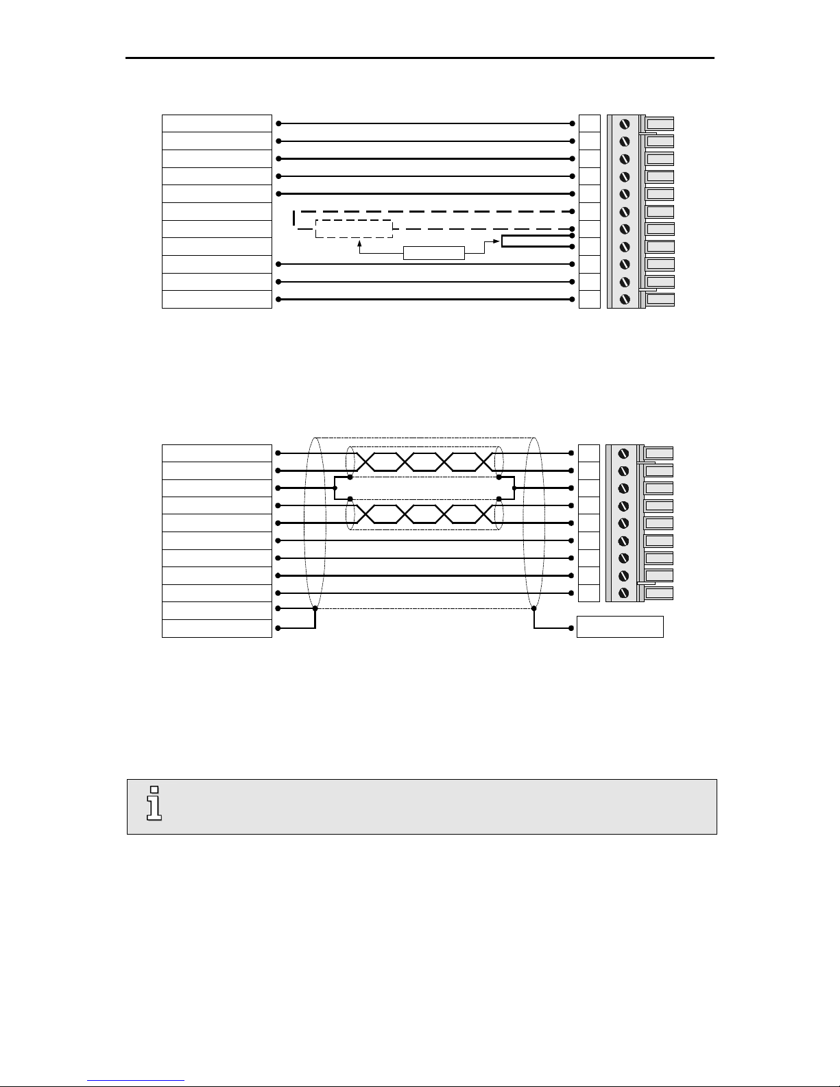
5.5 Pin configuration RS232 [X5]
Pin No. Denomination Value Specification
1 - - Not occupied
6 - - Not occupied
2 RxD 10 V / RI > 2kΩ Receive line, RS232 specification
7 - - Not occupied
3 TxD 10 V / RA < 2kΩ Transmitting line, RS232 specification
8 - - Not occupied
4 +RS485 - Reserve for option RS485 Interface
9 -RS485 - Reserve for option RS485 Interface
5 GND 0V In terfaces GND, galvanically connected to DGND
Servo
Positioning
Controller
PC
2
3
4
5
6
7
8
1
9
1
5
9
6
Connector
housing
2
3
4
5
6
7
8
1
9
1
5
9
6
Female Female
Connector
housing

Electrical installation Page 24
5.6 Wiring diagram Motor [X6] and Power Supply [X9]
Resolver / Encoder
SM
E
24V / 2A
for the
holding brake
Power Supply [X9]
Motor feedback [X2A] / [X2B]
ARS 2302 FS, 2305 FS and 2310 FS
24V Supply
Motor feedback
T
Permanent-magnet
synchronous maschine
Ground conductor from motor
L 3
PE
+24V
0V
F1
External brake
resistor
Bridge circuit for
internal brake resistor
alternative !
L 2
ZK+ Pos. DC bus voltage
ZK- Neg. DC bus voltage
BR-INT
Connection of internal brake
resistor
BR-CH
Brake chopper connection for
internal/external brake resistor
PE
Connection ground conductor from
mains
+24V
Supply for control part (1A) and
holding brake (2A)
GND24V Reference potential supply
Mains phase 2
L 3
Motor [X6]
U
Motor phase 2
W Motor phase 3
PE Ground connection from motor
MT+
Motor temperature sensor, normally
closed contact, PTC, KTY...
MT-
PE
Cable shield from holding brake
and motor temperature sensor
BR+
BR-
Holding brake, signal level
depentdent on switch status,
high side / low side sw i tch
Motor phase 1
V
L 1
Mains phase 1
Mains phase 3
230VAC ... 480 VAC
+/- 10%
L 2
L 1
BR-EXT
Connection of external brake
resistor
main fuse
Figure 5: Connection to power supply [X9] and motor [X6]
The servo positioning controller ARS 2300 FS is connected to the supply voltage, the motor, t he brake
resistor and the holding brakes as shown in Figure 5. The operation of the servo positioning controller
ARS 2300 FS requires a 24V supply source for the electronics, which is connected to the terminals
+24V and GND24V. The connection to the supply for the power output stage is either made to
terminals L1, L2 and L3 for AC supply or to ZK+ and ZK- for DC supply.
Electrical installation Page 25
PHOENIX-COMBICON at the [X9]
1
4
7
9
2
5
8
3
Power supply
6
BR-CH
L1
L2
L3
PE
BR-INT
ZK-
BR-EXT
ZK+
GND24V
+24V
11
10
External
brake resistor
alternative !
The motor is connected to the terminals U,V,W via motor cable to [X6].
The motor temperature sensore is connected to terminals MT+ and MT-, if it is lead into one cable
together with the motor phases. If a temperature sensor (e.g. KTY81) is used in the motor, i t is
connected via the encoder cable to [X2A] or [X2B].
PHOENIX-COMBICON at the [X6]
PE (optional)
Motor Phase U resp. 1
Motor Phase V resp. 2
Motor Phase W resp. 3
BRBR+
MT+
MT-
Motor s ide connect or
PE (Motor)
1
4
7
9
2
5
8
3
6
Connector housing
Motor housing
Cable shield
(PE terminal)
Connect the inner shields to PIN 3; maximum length 40 mm.
Length of unshielded cores maximum 35 mm.
Connect total shield on controller side flat to PE terminal; maximum l ength 40 mm. Use shield
clamp (SK14) or connect to PE screw terminal
Connect total shield on motor side flat to connector or motor housing; maximum length 40 mm .
The cable shield of the motor cable must also be connected to the controller housing
(PE screw terminal).
The connection of the shaft encoder via the D-Sub connector to [X2A] / [X2B] is roughly shown in
Figure 5.
The servo positioning controller ARS 2300 FS must be connected to ground with its PE connection.
The ARS 2300 FS must be completely wired first (excepted [X2B], see information mark below). Only
then may the operating voltages for the DC bus and the electronics supply be switched on. In the case
of inversed wiring of the operating voltage connections, excessive operating voltage or in the case of
confusing the connections for operating voltage and motor the servo positioning controller will be
damaged.

Electrical installation Page 26
The signals for the temperature sensor "MT-" (PIN 4) and "MT+" (PIN 5) on the motor
connector plug [X6] are not situated on safety extra-low voltage
(PELV - protective extra-low voltage). The connections are designed for non-PELV
temperature sensors. The isolation to PELV is part inside the ARS 2000 FS.
If the power supply is too high, the angle encoder can be destroyed! Make sure that you
have set the correct supply voltage before connected to [X2B]!

Electrical installation Page 27
5.7 Pin configuration Incremental Encoder Input [X10]
Pin No. Denomination Value Specification
1 A / CLK 5V / RI ≈ 120Ω Incr emental encoder signal A /
Stepper motor signal CLK
pos. polarity as per RS422
6 #A / #CLK 5V / RI ≈ 120Ω Incr emental encoder signal A /
Stepper motor signal CLK
neg. polarity as per RS422
2 B / DIR 5V / RI ≈ 120Ω Incr emental encoder signal B /
Stepper motor signal DIR
pos. polarity as per RS422
7 #B / #DIR 5V / RI ≈ 120Ω Incr emental encoder signal B /
Stepper motor signal DIR
neg. polarity as per RS422
3 N 5V / RI ≈ 120Ω Incremental encoder index pulse N
pos. polarity as per RS422
8 #N 5V / RI ≈ 120Ω Incremental encoder index pulse N
neg. polarity as per RS422
4 GND - Supply GND for encoder
9 GND - Shield for the connection cable
5 VCC +5V±5% 100mA Auxiliary supply, load with 100mA maximum,
short circuit-proof
2
3
4
5
6
7
8
1
9
Connector
housing
1
5
9
6
#B / #DIR
B / DIR
N
A / CLK
#N
GND
VCC
#A / #CLK
Incremental encoder input
D-SUB
connector at
X10
Male
Cable shield
(optional)
Connector housing

Electrical installation Page 28
5.8 Pin configuration Incremental Encoder Output [X11]
Pin No. Denomination Value Specification
1 A 5V / RA ≈ 66Ω *) Incremental encoder signal A
6 #A 5V / RA ≈ 66Ω *) Incremental encoder signal #A
2 B 5V / RA ≈ 66Ω *) Incremental encoder signal B
7 #B 5V / RA ≈ 66Ω *) Incremental encoder signal #B
3 N 5V / RA ≈ 66Ω *) Incremental encoder index pulse N
8 #N 5V / RA ≈ 66Ω *) Incremental encoder index pulse #N
4 GND - Reference GND f or encoder
9 GND - Shield for connection cable
5 VCC +5V ±5% 100mA
Auxiliary supply, to be loaded with maximal 100mA,
short-circuit-proof
*) The value for RA is the differential output resistance
2
3
4
5
6
7
8
1
9
Connector
housing
1
5
9
6
#B
B
N
A
#N
GND
VCC
#A
Incremental encoder
output
D-SUB
connector at
X11
Male
Cable shield
(optional)
Connector housing

Electrical installation Page 29
5.9 Ethernet communication (UDP interface) [X18]
The UDP communication enables the connection of the ARS 2300 FS servo positioning controller to
the Ethernet fieldbus system. The communication via the UDP interface [X 18] is realised with the aid
of a standard cabling.
UDP interface [X18] Values
Function Ethernet, 10/100 MBaud (auto select)
Connector type RJ45
5.10 USB communication [X19]
The ARS 2300 FS servo positioning controller comprises a USB (universal serial bus) communication
interface, which is for connection via PC and for using the parameterisation tool Metronix
ServoCommander
®
.
The USB communication interface requires no auxiliary power supply.
USB interface [X19]
Connector type USB-B
Standard 2.0
Transmission rate Support for both full-speed (12 Mbps) and high-speed (480 Mbps)
modes
Communication protocl Metronix specific (generic device)
Functionality Slave-Client
Pin configuration
1 VCC +5 VDC
2 D- Data 3 D+ Data +
4 GND Ground

Functional Safety (optional) Page 30
5.11 SD/SDHC/MMC card slot
The ARS 2300 FS servo drive comprises a SD/SDHC/MMC card slot for the support of Firmware
downloads (initialisation via boot switches) and uploads and downloads of parameter sets.
SD card slot
Card types SD, SDHC and MMC
File systems FAT12, FAT16 and FAT32
Functions Load a parameter set (DCO
file), save the current parameter set (DCO file),
load a firmware file
File names
Only file and directory names according to the 8.3 standard are supported.
5.11.1 BOOT-DIP-Switch
During a restart/reset, the BOOT-DIP-Switch is used to determine whether to perform a firmware
download from the SD/MMC card or not. The position of the switch is shown in Figure 1.
BOOT-DIP-Switch in position “ON” firmware download requested
BOOT-DIP-Switch in position “OFF” firmware download not requested
When there is no SD/MMC card in the card slot of the servo drive and the BOOT-DIP-Switch is in the
position “ON” (firmware download requested), the error 29-0 is triggered after a restart/reset.
This error stops all further performances. This means that there is no communication possible via
USB.

Functional Safety (optional) Page 31
6 Functional Safety (optional)
6.1 Overview module types and integrated Functional
Safety
Module type Integrated Functional Safety
FSM 2.0 - FBA none FBA = Fieldbus activation
This module is equipped with DIP switches for activation and
controlling the fieldbus communication.
The functionality of the DIP switches is identical to the
functionality of the DIP switches of the modules FSM 2.0 – STO
and FSM 2.0 - MOV.
FSM 2.0 – STO STO “Safe Torque Off” (STO) with SIL3 in accordance with
EN 61800-5-2 / EN 62061 / IEC 61508 or category 4 /
PL e in accordance with EN ISO 13849-1.
FSM 2.0 – MOV STO, SS1, SS2,
SOS, SLS, SSR,
SSM, SBC
Safety functions in accordance with EN 61800-5-2, SIL3 in
accordance with EN 61800-5-2, EN 61508 and EN 62061 ,
PL e in accordance with EN ISO 13849-1
1)
1) Maximum achievable classification, limitations dependent on the safety func t ion a s wel l a s c irc ui t ry and the
encoders.

Functional Safety (optional) Page 32
6.2 FSM 2.0 – FBA
6.2.1 Fieldbus specific functional assignment of the DIP switches
DIP switch Functionally of the DIP switch (fieldbus specific with technology module)
CAN
(in the basic device)
PROFIBUS Sercos (without
DIP switch)
EtherCAT
8 Communication:
1: On
0: Off
Communication:
1: On
0: Off
Communication:
1: On
0: Off
Communication:
1: On
0: Off
1)
7 Baudrate:
11: 1 MBaud
10: 500 kBaud
01: 250 KBaud
00: 125 kBaud
Slave address
respectively
address offset
2)
:
0 .. 127
valid range:
3 .. 125
Baudrate:
11: 16 MBaud
10: 8 MBaud
01: 4 MBaud
00: 2 MBaud
No function
1)
6
5 Node address
respectively address
offset
2)
:
1 ... 31
Drive address
respectively address
offset
2)
:
1 ... 31
4
3
2
1
1)
If all DIP switches == 0: automatic start-up of EtherCAT is activated EtherCAT is switched on.
If at least one of the DIP switches 1 to 7 <> 0 and DIP switch 8 == 0: no automatic start-up of EtherCAT
EtherCAT is switched off.
2)
If necessary, the addresses will be added as an offset of a predefined base address of the corresponding bus system.
The base address can be predefined in the Metronix ServoCommander
®
and can then be saved in the parameter set of
the ARS 2000 FS.
Please note that the module FSM 2.0 – FBA does not offer any safety functionalities.

Functional Safety (optional) Page 33
6.3 FSM 2.0 – STO
6.3.1 Features
The Functional Safety Module FSM 2.0 – STO serves as an expansion of the servo positioning
controller ARS 2000 FS.
It reaches the function “Safe Torque Off” (STO) with SIL3 according to EN 61800-5-2 / EN 62061 /
IEC 61508 or category 4 / PL e according to EN ISO 13849-1.
It reaches the function “Safe Torque Off” (STO) with SIL3 in accordance with EN 61800-5-2 and
PL e in accordance with EN 13849-1.
It is equipped with a floating feedback contact.
It can be simply plugged into the basic unit from the outside, so that it can be used f or upgrading
systems that are already equipped with ARS 2300 FS servo positioning controllers.
It is exclusively suitable for the ARS 2000 FS product range.
It offers a user-friendly parameterisation with the Metronix ServoCommander
®
software.
DANGER!
The function STO as a sole safety function is not sufficient for drives under
permanent torque, such as hanging loads.
DANGER!
For drives, the function STO must be validated after installation and after any
changes of the installation.
This validation must be documented by the commissioning engineer.
6.3.2 Pin assignment [X40]
Pin no. Name Value Specification
8 0V 0 V Reference potential for internal controller supply
7 24V +24 V DC 24 V supply out
6 C2 Feedback contact for the state “STO ” to an external
control
5 C1
4 0V_B 0 V Reference po ten tial for S TOB
3 STOB 0 V / 24 V Control input B for the function STO
2 0V_A 0 V Reference p otential for STOA
1 STOA 0 V / 24 V Control input A for the function STO
The functionality of the DIP switches is identical to the functionality of the DIP switches
of the module FSM 2.0 – FBA.

Functional Safety (optional) Page 34
6.4 FSM 2.0 – MOV
6.4.1 Features
The Functional Safety Module FSM 2.0 – MOV serves as an expansion of the servo positioning
controller ARS 2000 FS to implement the safety functions:
STO – Safe Torque Off
SS1 – Safe Stop 1
SS2 – Safe Stop 2
SOS – Safe Operating Stop
SLS – Safely-Limited Speed
SSR – Safe Speed Range
SSM – Safe Speed Monitor
SBC – Safe Brake Control
When suitable position transmitters are used and with suitable activation of the safety module, the
requirements are fulfilled in accordance with EN 61800-5-2 up to and including SIL3 and in
accordance with EN ISO 13849-1 up to and including Category 4 / PL e.
Depending on the encoders used for position recording, it is possible that only SIL2 is
implemented
It is equipped with a floating feedback contact.
It can be simply plugged into the basic unit from the outside, so that it can be used f or upgrading
systems that are already equipped with ARS 2100 FS servo positioning controllers.
It is exclusively suitable for the ARS 2000 FS product range.
It offers a user-friendly parameterisation with the Metronix ServoCommander® software wit h
including the SafetyTool.
DANGER!
The function STO as a sole safety function is not sufficient for drives under
permanent torque, such as hanging loads.
DANGER!
For drives, the safety functions must be validated after installation and after any
changes to the installation.
This validation must be documented by the commissioning engineer.

Functional Safety (optional) Page 35
6.4.2 Pin assignment [X40]
Pin
Designation Description (factory setting1))
X40A plug connector
1 DIN40A Digital input 40, two-channel
(Factory setting: Emergency stop switching device, STO and SBC request)
2 DIN40B
3 DIN42A
Digital input 42, two-channel
4 DIN42B
5 DOUT40A
Digital output 40, two-channel
6 DOUT40B
7 DIN44
Digital input 44
(Factory setting: Brake feedback)
8 DIN45
Digital inputs 45, 46, 47
(Factory setting: Mode selector switch)
9 DIN46
10 DIN47
11 DIN48
Digital input 48
(Factory setting: Error acknowledgement).
12 DIN49
Digital input 49
(Factory setting: Terminate safety function on rising edge).
X40B plug connector
13 DIN41A
Digital input 41, two-channel
14 DIN41B
15 DIN43A
Digital input 43, two-channel
16 DIN43B
17 DOUT41A
Digital output 41, two-channel
18 DOUT41B
19 DOUT42A
Digital output 42, two-channel
20 DOUT42B
21 C1
Signal contact, relay contacts
(Factory setting: Safe state reached, no safety condition violated).
– Opened: “Safety function not active”
– Closed: “Safety function active”
22 C2
23 GND24
0 V, reference potential for DINx / DOUTx / +24 V
24 +24 V
24 V output, auxiliary supply, e.g. for safety peripherals
(24 V DC logic supply of the motor controller).
1)
Function when the device is delivered or after resetting to factory se tt i ngs
(advanced parameterisation)
The functionality of the DIP switches is identical to the functionality of the DIP switches
of the module FSM 2.0 – FBA.

Functional Safety (optional) Page 36
6.5 Mechanical installation FSM 2.0
As a standard, the ARS 2300 FS series servo positioning controllers come supplied with the module
FSM 2.0 – FBA (short “FBA module”) integrated in the FSM slot.
You can remove the FBA module and replace it with a Functional Safety Module FSM 2.0 – STO or
FSM 2.0 – MOV (short “safety module“).
DANGER!
The servo positioning controller must be disconnected from any current-carrying
connections prior to the installation of the module.
To remove the FBA module from the servo positioning controller and then insert the safety module
module, please proceed as follows:
1. Remove the two fastening screws of the FBA module with a suitable Phillips screwdriver.
2. Loosen the FBA module a few millimetres by levering it slightly at the recesses of the upper and
lower edges of the front plate.
3. Remove the FBA module completely from the FSM slot.
4. Push the safety module module into the open FSM slot so that the lateral guides hold the board.
5. Push the safety module module into the slot and carefully into the connector at the backside of the
servo positioning controller until it reaches the stop.
6. Screw the safety module module onto the front side of the housing of the servo positioning
controller with the two fastening screws.
7. Ensure that the front plate of the safety module module has conducting contact with the housing of
the servo positioning controller.

EMC-compliant cabling Page 37
7 EMC-compliant cabling
The following must be considered for an EMC-compliant setup of the drive system:
In the first environment, the servo positioning controller ARS 2300 FS must be install ed in a st eel
switch cabinet. In most cases a standard model will sufficiently attenuate emitted interference. The
cable shields must be connected with the switch cabinet housing by means of metal cable glands.
In the second environment the servo positioning controller ARS 2300 FS can also be used without
a steel control cabinet. Installation in a control cabinet (possibly plastic), however, is still
necessary to guarantee proper usage.
The control cabinet bed plate must be conducting (zinc-coated design). The imperative central
grounding point should also be located on the control cabinet bed plate.
The signal lines must be as far away from the power cables as possible. They should not be
placed parallel. If intersections cannot be avoided, they should be perpendicular (i.e. at a 90°
angle), if possible.
In order to keep the leakage currents and the losses in the motor connection cable as small as
possible, the servo positioning controller ARS 2300 FS should be located as close to the motor as
possible (see also the following chapter).
The shield of the motor cable is connected to the housing of the servo positioning controller
ARS 2300 FS (shield connection terminal). In the first environment the shield of the motor cable
also has to be connected to the control cabinet housing by means of metal cable glands.
The mains-end PE connection is connected to the PE connection point of the supply connection
[X9].
The inner PE conductor of the motor cable is connected to the PE connection point of the mot or
connection [X6].
Motor cable and angle encoder cable must be shielded.
Unshielded signal and control lines should not be used. If their use is inevitable they should at
least be twisted.
Even shielded cables will inevitably have short unshielded ends (unless shielded connector
housings are used). In general, the following applies:
Connect the inner shields to the corresponding pins of the connectors; Maximum length
40 mm
Length of the unshielded cores 35 mm maximum
Connect the total shield on the controller side flat to the PE terminal; Maximum l ength 40 mm
Connect the total shield on the motor side flat to the connector housing or motor housing;
Maximum length 40 mm
Caution!
In residential surroundings this product may cause high frequency disturbances, which
may require interference rejection measures.

EMC-compliant cabling Page 38
DANGER!
For safety reasons, all PE ground conductors must be connected prior to initial
operation.
The EN 50178 regulations for protective earthing must be complied with during
installation!
7.1 Operation with long motor cables
In applications involving long motor cables and/or unsuitable motor cables with an inadvertently high
cable capacity, the filters may be thermally overloaded. To avoid such problems we highly recomm end
the following procedure for applications that require long motor cables:
As of a cable length of more than 25 m, only use cable with less than 150 pF/m (capacitance per
unit length) between the motor phase and the shield!
(Please contact your motor cable supplier if necessary).
Lower the power stage clock frequency when using cable lengths of 25 m or longer.
Both measures are also good for the EMC behavior of the entire drive:
The servo positioning controller generates less and less severe interference and the emission of
interference into the mains is reduced.

Additional requirements for the servo drives concerning the UL approval Page 39
8 Additional requirements for the
servo drives concerning the UL
approval
This chapter gives further information concerning the UL approval of the ARS 2302 FS, ARS 2305 FS
and ARS 2310 FS.
8.1 Circuit protection
In case of a required UL-certification the following data for the main fuse are to be
considered:
Listed Circuit Breaker according to UL 489, rated 480Y/277 Vac, 16 A,
SCR 10 kA
8.2 Wiring and environment regards
Use 60/75 or 75°C copper (CU) wire only.
The terminal tightening torque is 0.22...0.25 Nm.
To be used in a Pollution Degree 2 environment only.
8.3 Motor temperature sensor
Motor overtemperature sensing is not provided by the drive according to UL.
When a UL-certification is required, then in order to prevent motor overtemperatures the servo drives
may only be operated in connection with motors that are provided with an integrated motor
temperature sensor. The sensor has to be connected to the servo drive and the temperature
monitoring has to be activated accordingly on the software side.
 Loading...