

MET447
Digital Satellite Receiver
3500 channels
Parental Control
2 Scarts
DiSEqC 1.2
Timer
SIGNAL

www.metronic.com

3
www.metronic.com
Your TouchBOX 2 has ventilation slots. These slots must not be obstructed, even partially, in order to ensure proper ventilation. The lifetime and normal functioning of your device
depends on these factors. Installation in premises which are confined or subject to temperature or dampness changes (sheds, attics, cellars, tiny rooms, dry risers etc.) may cause an
overheating of the device or a premature ageing resulting in failures that are not covered by
the guarantee.
Never open the TouchBox 2 receiver even when it is not connected, because it contains
electrical components, which can be dangerous for you. In general electrical appliances are
not connecting to earth, so you can get electrical discharge (which is not risky), while implemented the connections. Our advice is to connect the equipment after all the sockets connections have been made.
To clean the receiver or his remote control does not use any solvent or detergent. Only use
a dry cloth for dust or slightly dampened with water for the front face. Always carry out this
operation after disconnecting the receiver from the main socket and from the satellite coaxial
cable.
For your own safety:
Never open the device. It contains no item that can be fixed by the user. If you open it,
make some changes on circuits or connections of non-compliant equipment it will cancel the
guarantee. Please return it for maintenance or repair to the point of sale if the device is under
guarantee, or to a qualified technician, if it is no longer under warranty. In order to reduce the
risks of fire, electrocution or damage caused to another equipment or someone, do not expose
the device to dampness, bad weather, dust, sand, radio electric radiation, sun, cold or high
temperature. You must use the device between 0°C to 40°C; 32°F to 104°F. Regarding to the
location, please avoid putting fabric, paper (magazines), plastic bags, a vase etc. Place your
Digital Satellite receiver in a dry place, safe from dust. It is not designed for outdoor use.
The remote control needs two AA 1.5V batteries. Check the polarity before fitting them into
the remote control. Do not throw your used battery in the bins; take them to your local store
where special boxes are provided to recycle them.
The installation and the use of the receiver are based on pre-programmed channels. In
the event of problem on a channel, get a specialized magazine to find out if this channel is
still Free To Air. For information, the operators frequently change the channel’s characteristics
without notice.
Your receiver is compatible with DiSEqC 1.2; it could be used then with a DiSEqC 1.2
motor (or rotator). In case of a DiSEqC 1.2 motorized installation, our advice is to install the
engine in an easily accessible location (avoid chimneys, for example). Indeed, an engine may
have to be screwed up or lubricated... An installation in a not very accessible place would be
difficult for you. For your information, the DiSEqC standard is a trademark by Eutelsat.
If you only have one digital tuner, you will not be able to record a different satellite channel
from the one you are watching. So we advise you to keep your terrestrial aerial if you have
already one.
Some channels, even if they are broadcasted Free To Air (you do not need a subscription)
are only for adults. To preserve your children of watching it, we advise you to install a parental
control and block these channels.
CAUTION

www.metronic.com
www.metronic.com
• The receiver’s programming will have to go through menus. For an easy use of this User
Manual and for a more friendly use of the user’s manual we put it as: MENU / menu / sub-
menu.
For example, when you read:
• Go in MAIN MENU / Installation / LNB & switches setup,
it is equivalent to :
• Press on MAIN MENU to go to the main menu.
• Press on 6 key to select the Installation menu.
• Press on OK to validate.
• Press on 6 key to selct the sub-menu / LNB & switches setup
• Press on OK to validate.
• You will notice that the words in bold in this user manual are the same than in the MENU
which appeared on the screen of your television.
This symbol is used on several occasions in this user manual. Pay the necessary
attention to it, the text point out by it is very important.
5
www.metronic.com
1 General description page 06
2
Installation of fixed satellite dish on a receiver page 10
3 Installation of several satellites page 11
4 Installation of a motorised unit page 13
5 Connection on a fixed satellite dish already aligned on a satellite page 24
6 Connection on a Bi-head system Astra19,2°+HotBird13°already aligned page 24
7 Connection on a DiSEqC 1.2 motorised system already aligned page 25
8 Remote control description page 27
9 Receiver description page 28
10 Day to day use page 28
11
Access a channel page 28
12 Add a channel page 29
13 Modify / Organise channels / Manage favorites page 32
14 Miscellaneous adjustment page 34
15 Reset the receiver page 36
16 Connection with an analogue receiver and a VCR page 36
17 Use with a VCR page 37
18 In case of problem page 37
19 Mechanical stops adjustment (with a DiSEqC 1.2 motor) page 38
20 Inclinometer for motor, ref 450907-8 page 39
Quality questionnaire
page 41
Assistance and advice
page 43
Channel guide
page 44
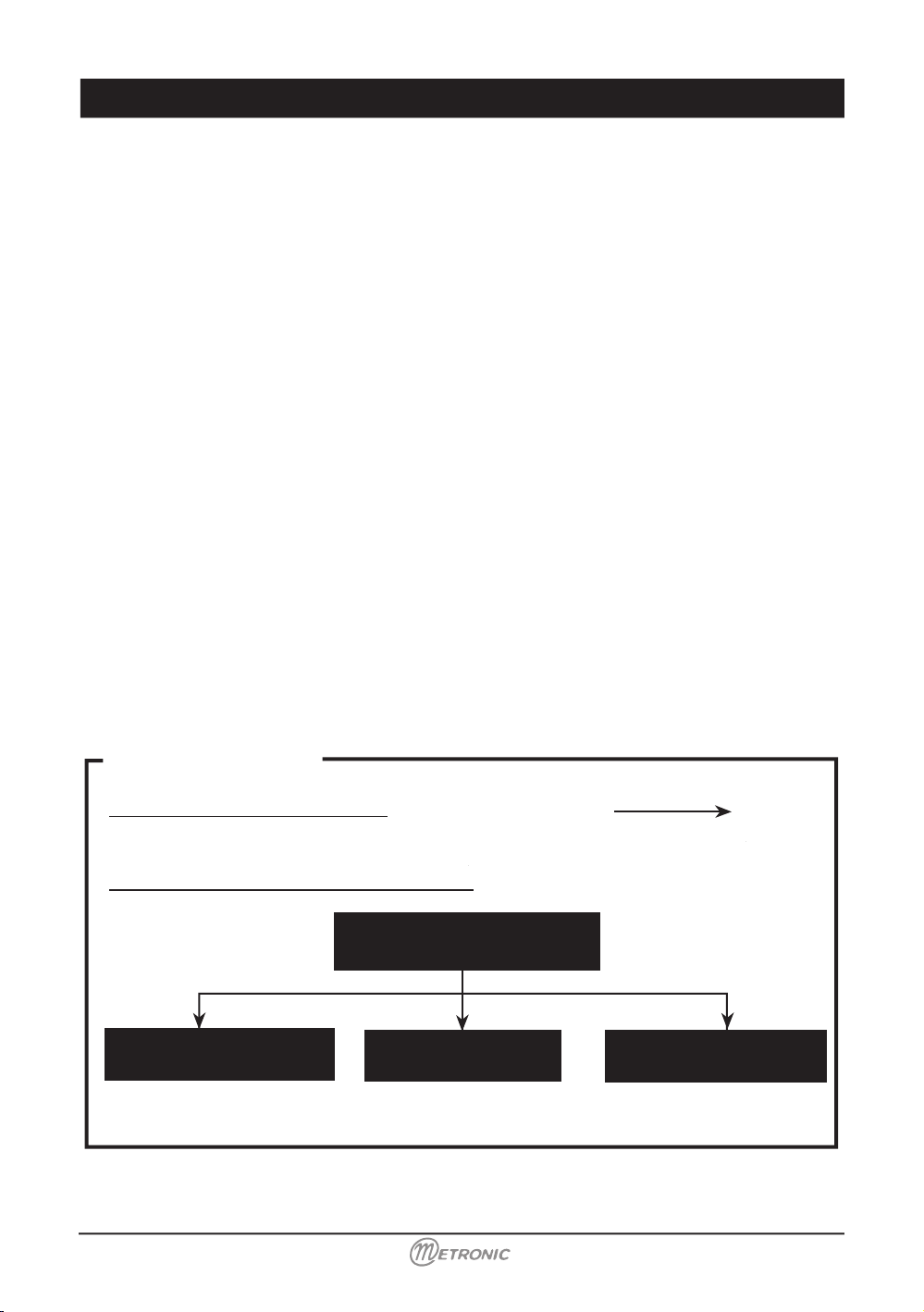
installation shortcut:
Purchase of the receiver alone
page 28
(your satellite is already aligned)
Purchase of the receiver + satellite dish:
Table of contents
Installation / General points
page 06
Satellite dish head
page 10
Satellite dish 2 head
page 11
Motorized satellite dish
page 13
6
www.metronic.com
www.metronic.com
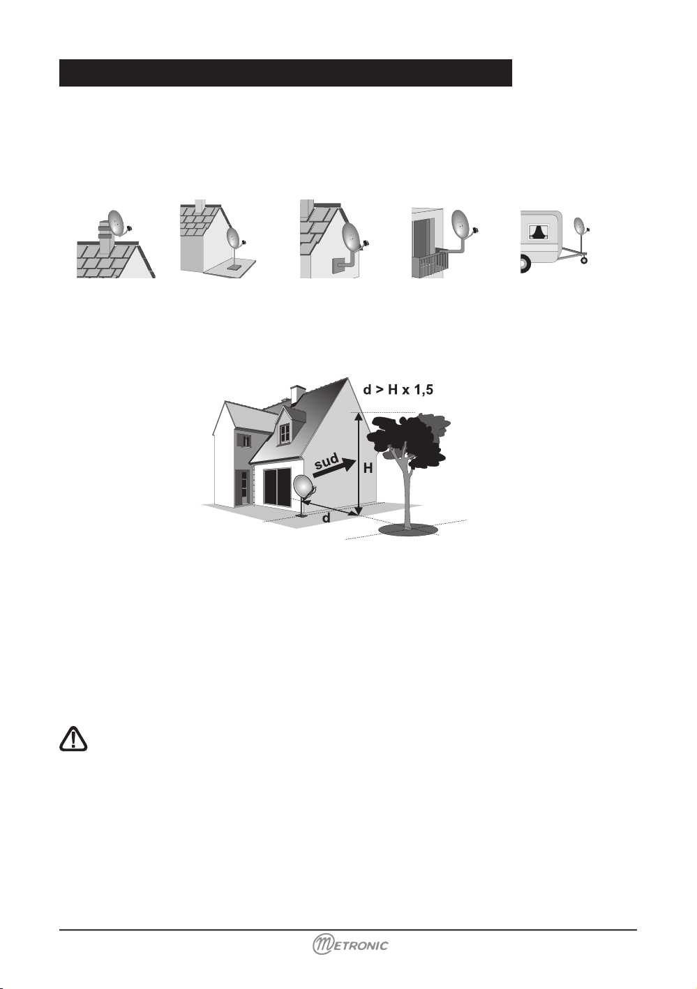
A - Choice of the location and satellite dish assembling
Whatever your choice of installation, your fixing must be stable and vertical.
In the event of an obstacle, respect the rule of distances explained below
Example: if your satellite dish is 2m above the ground, and a building, or a tree, with 10 m high
might obstruct, then the buildings needs to be at more than 12m.
For the satellite dish assembly, look in the user manual provided in the satellite dish screw
bag.
CAUTION: Please handle the satellite dish with precaution because his surround may
be sharp.
1 - Installation - General installation advice
www.metronic.com
SIGNAL
1
2
3
4
9
9
10
6
8
7
5
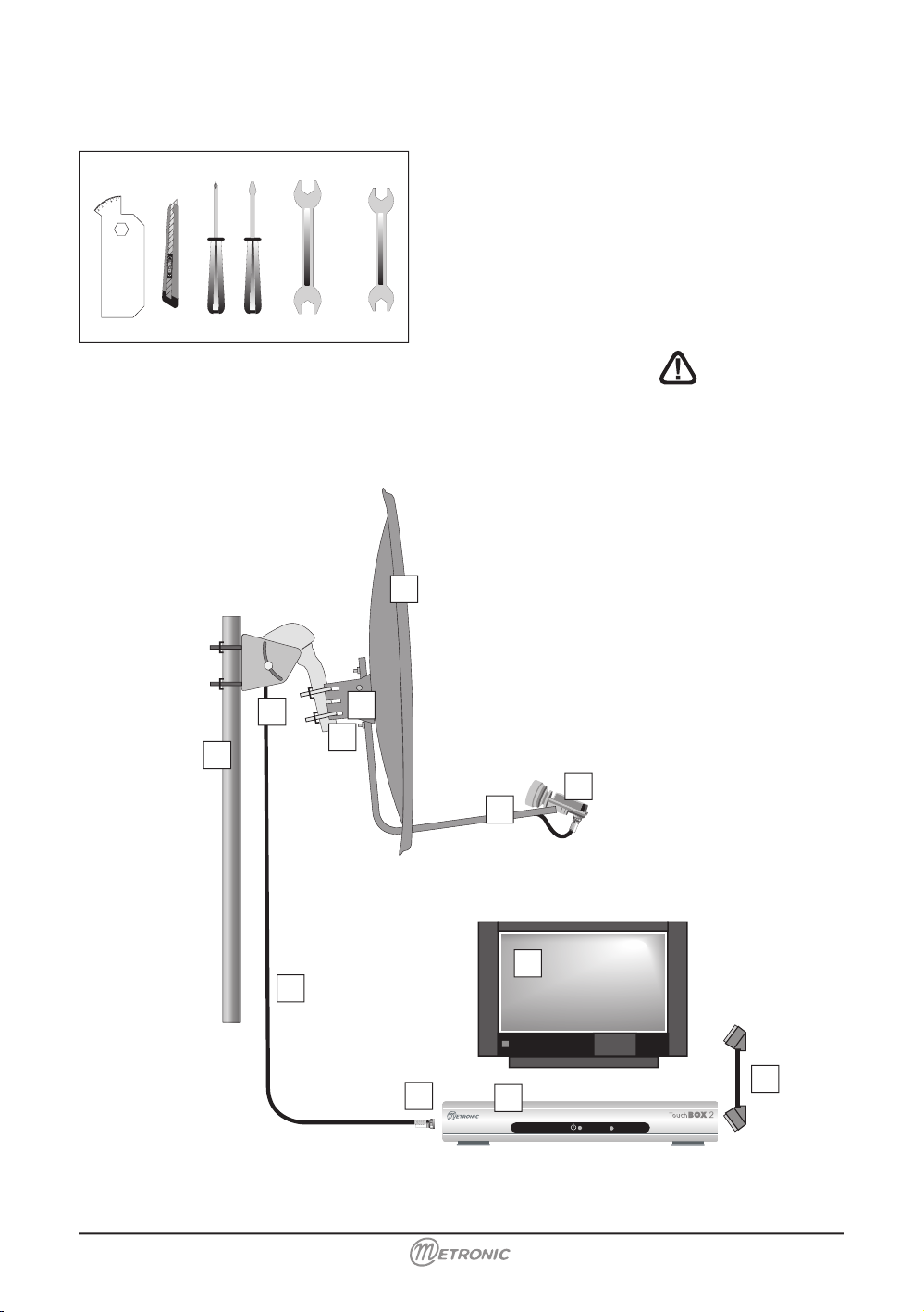
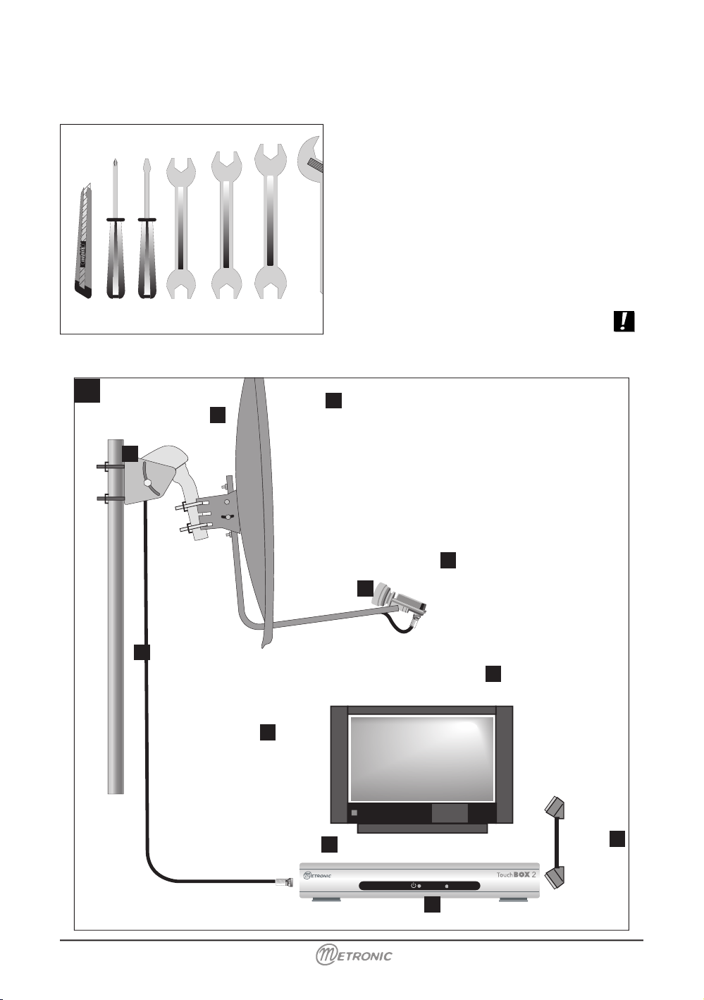
B - Necessary parts and tools :
1 Satellite dish
2 Screws and fixing
3 Offset arms
4 Universal LNB
5 Pole or wall mmounting bracket of Ø minimum
recommended : 40 mm
6 Digital satellite receiver with remote control
7 TV PAL or PAL/ SECAM
8 Scart lead 21 pins
9 «F» plug
10 Special satellite cable, the standard TV
cable is not appropriate.
13 mm
11 mm
12 mm
10 mm
9
8
www.metronic.com
www.metronic.com
D
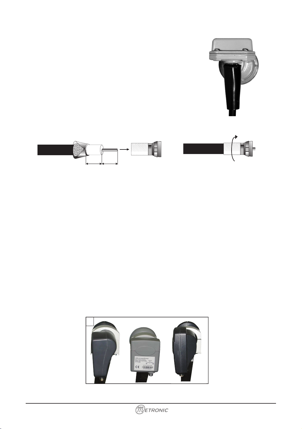
C - Assembly and insulation of the «F» plug
• The plug must be screwed on the strip iron aluminium,
which you have peeled back on the exterior cable. Take
care that there is not a strand of the braid in contact with
the central heart of the coaxial cable.
• When your installation is finished, do not forget to isolate
the LNB with insulation paste or in case use some silicone
gel (see picture opposite).
LNBs badly insulated or not insulated at all are not covered
by the guarantee.
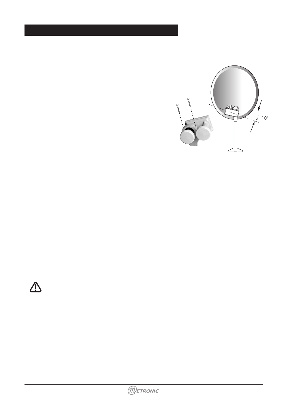
D - LNB’s assembly
• Your kit can contain various types of LNB
• LNB in metal grey (D1 schema): make sure to position the triangular mark (5) properly
upwards. It is normal that the body of the head is tilted on 45°, the cable leaves tilted to
45°.
• Another LNB (graduations): must be positioned vertically. See D2 schema (the cable leaves
vertically).
• Install the LNB at the end of the offset arm (see example below)
In both cases, never remove the protection cap of the horn.
5 mm
8 mm
9
www.metronic.com
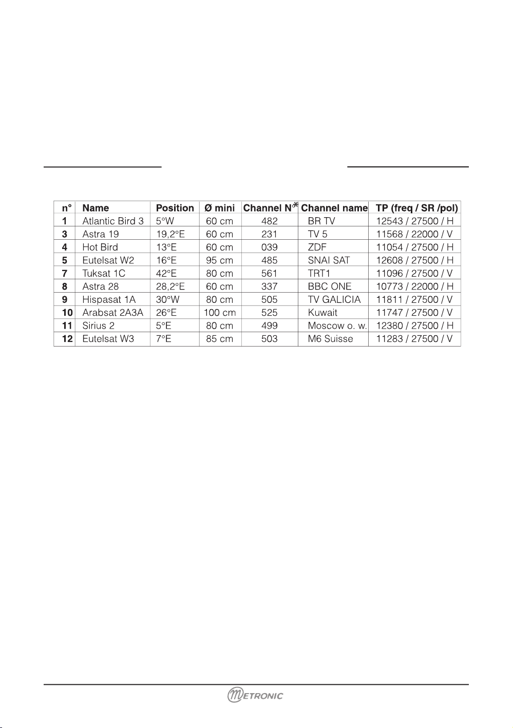
E - Pre-programmed channels and satellites
Your receiver is delivered pre-programmed on the main satellites available in Europe. Some
satellites require a one-meter satellite dish; you will not be able to receive them with a lower
size satellite dish, even if this satellite appears in your pre-programmed channels list. You
will use these channels to point your satellite dish towards the satellite you want. The Table
1 gives you the satellite dish necessary size, in the United Kingdom and the Republic of
Ireland, for each satellite, as well as references channel that will be useful for you to align
with a satellite.
Important notes:
Table 1 does not mention the satellites which do not emit (or with a very low signal) on Digital
Free to Air. The reference channels were validated at the time of drafting this user manual, we
cannot guarantee they will still be there. In the event of a problem at the time of the search
for a satellite, get specialized magazines (like What satellite and Digital TV) to check that the
reference channel is still a Free to Air channel.
For the alignment, you must imperatively know which satellite you wish to receive. If you have
any doubt check the pre-programmed channels at the end of this user manual. You will then
be able to choose the satellite depending on the channel that you wish.
F - Choice of language
When you start your receiver for the first time, you need to select the language you want with
the arrows
56 and then validate by OK. If you do not have the choice, we strongly advise
you to reset the receiver (see §15). You have to do this choice, as well, after resetting the
receiver.
Table 1: referencesʼ channel
(*) The channels numbers apply to the TV list at output of factory. If you modify the programming, these channels numbers are not valid any more.

www.metronic.com
www.metronic.com
2 - Installation of a xed dish on a satellite
A - Connections
The receiver must be disconnected from the power supply, connect directly the LNB to the
receiver LNB input. Connect the television to the receiver scart socket output. Switch on the
television and connect the receiver to the power supply. Press on the
key on the remote
control, the green LED ignites.
If the television does not display a black screen with a message “ No signal or bad signal “,
checks the scart leads connections and/or force the A/V or EXT mode of your television (see
your TV user manual).
B - Alignment / Satellite dish orientation
Find in Table 1 (page 9) the satellite reference channel number that you wish to receive. Type
on the remote control this channel number.
• Press on the remote control INFO key to show the reception gauge quality level at the
bottom of the screen. This indicator indicates normally 0% quality; the alignment will consist
in directing the satellite dish toward the satellite, which receives the maximum signal then
the quality. The maximum level is not important. What is important is the variation. When
you approach a satellite the level increase. When the quality increase, that means generally
that you are on the right satellite.
• Put the satellite dish vertically (the graduations on the back indicate 20-25°) and roughly
direct it towards the south. Make a slow sweeping (about 20 seconds) of a quarter of spin
on the left then a quarter of spin on the right while checking on the television. The indicator
should not show anything at this stage.
• Incline the satellite dish by 2 degrees (about 2cm on the top of the satellite dish) towards
the top and then start again the sweeping.
• Proceed by 2 degrees step until the indicator goes up and that the channel appears. Tighten
all the screws definitively, except those which fix the LNB in its support. If the indicator
increases, but no images appear on the screen, you are on another satellite, it is necessary
to continue sweeping.
C - Adjustment of counter polarization
Spin the LNB clockwise in its support for a few degrees to further increase the level of signal. If the signal decreases, spin it in the other way. Once you obtain the best signal, tighten
definitively the screws from the LNB. Your installation is finished. Press on EXIT to erase the
information banner. You can now watch all the satellite channels from the satellite you just
aligned your satellite dish on.
www.metronic.com
A - Installation of a bi-head satellite dish Astra 19.2 + HotBird
If the receiver is in factory adjustment (new or after a
reset), you do not have to modify the programming to
install a Monobloc. In that case, install the Monobloc as
indicated on the pictures opposite, and align the satellite
dish on Hotbird as explained in the preceding paragraph.
For the general case, this paragraph explains how to
program the receiver for a Monobloc or any switch.
• Go in the menu Installation / LNB Setup.
• On the line LNB, select LNB2 with the keys 34.
• Check that the line DiSEqC input indique 2.
Programming
• Go into MENU / Installation / LNB Setup
• Go onto Satellite line and then press OK to show the
satellite list.
• Select Hot Bird and validate by OK.
• Go onto LNB, select LNB1 with arrows 34.
• Go onto the Satellite line and press on OK to make the satellite list to appear.
• Select Astra 19° then validate by OK.
• On the line LNB, select LNB2 with the keys 34.
• Press on EXIT to leave all the menus.
Alignment
•
Install the monobloc as schematised above.
•
Do the alignment on HotBird like on a fixed dish (see preceding page).
•
Check that you receive the Astra channels.
•
If necessary, refine the alignment to receive properly the both satellites.
You can now watch the pre-programmed channel on Astra 19.2 and Hot Bird (see «Day to
day use» page 30).
Warning : some monoblocs have a reversed command. It might be necessary
sometimes to reverse 1 et 2.
3 - Installation on several satellites

www.metronic.com
www.metronic.com
B - Installation of a switch
If you install 2 satellite dishes, or more, you need to connect all the LNB head to a switch to
run only one cable.
Install and align each satellite dish like they were alone, by connecting directly his LNB to the
receiver input.
When all the dishes are installed and aligned, modify the receiver programming (see underneath) to associate each satellite to the right switch input.
Example of satellite reception for Astra and HotBird. Astra is on the B input and HotBird on
the A input:
Programming
• Go into MENU / Installation / Channel Setup
• Go onto the line Satellite and press on OK to make the satellite list to appear. Select Hot
Bird then validate by OK.
• Go onto LNB, select LNB1 with the keys 34.
• Go onto Satellite and press on OK to make the satellite list to appear. Select Astra 19°
and validate by OK.
• On the line LNB, select LNB2 with the keys 34.
• Press on EXIT to leave all the menus.
@ You can now watch the channels from Astra 19 and HotBird (see “Day to Day use”
page 30).

www.metronic.com
A - Foreword
This user manual shows you how to install a motorized unit with the motor, ref: 450907-8. Such installation requires some operations, on the motor and on the satellite receiver with which it is supposed to
work. To ease the read of this procedure, we have written it in two parts. The first describe the repetitive
operations that you have to do with the receiver. In the second part (installation as such), these operations will simply be quoted and pinpointed by a figure.
4 - Continuous rotation
In the menu DiSEqC 1.2 (see above), scroll down on the line continuously moving.
Press once on 4 to start the sweeping towards the right (towards the west). Another press stops the
motor. The use of the key
3 makes it spin a step towards the east. If the line Auto Stop is setup as
On, the motor stops as soon as it gets a quality signal.
5 - Step by step rotation
In the menu DiSEqC 1.2 (see above), scroll down on the line move steps.
Press on 4 to make the motor spin a step towards the right (towards the west).
The use of the key 3 makes it spin a step towards the east.
Put the receiver on the satellite reference channel. Go into the paragraph 1E (page 9) and then locate
the satellite reference channel. In case this channel is not valid anymore, choose, when it is possible, any
channel with a debit (SR) above 20000.
2 - Go into the menu DiSEqC 1.2
If it is not done already, go into Menu / Installation / Antenna type. On the first line, choose “moved”
with the key and press on EXIT. Go into MENU / Installation / Channel setup / Dish Position, press on
OK.
3 - Reset the motor
In the menu DiSEqC 1.2 (see above), scroll down onto the line Other Commands.
Select Goto ref with the key 34 and press on OK.
4 - Installation of a motorised unit
6 - Gives a number to a satellite
Go into Menu / Installation / Channel Setup
Scroll down on the line Satellite Number and choose the number with the arrows.
@If you choose a number already used by another satellite, a bottom line message will indicate it to
you for 3 seconds. In case of a doubt, use the number given in the picture paragraph 1E (page 9).
Press on OK.
7 - Memorised the satellite position
In the menu DiSEqC 1.2 (see above), if you are either on line continuously moving or move steps, a
press on OK memorise the actual position.
8 - Display the level indicator
Press on the key Info on the remote control to display the level and quality indicator. This indicator shows normally
0% in quality; the alignment will be to orientate the satellite dish to get the maximum level of signal then the quality.
The maximum level is not important. What it is important it’s the variation. When you get close to a satellite, the level
increase. When the quality increase, that means generally that you are on the right satellite.
www.metronic.com
www.metronic.com
Elements:
1 Satellite dish
2 Screw and fixing
3 Offset arm
4 Universal LNB
5 Mast or stand off arm Recommended
diameter minimum: 40 mm (1,6’’)
6 Satellite receiver
7 TV set PAL for digital reception and
PAL/SECAM for analogue (to be able
to watch it in colour)
8 Scart lead male/male 21 pin
9 «F» plug
10 Cable special for satellite,
(regular TV cable may not work)
11 Motor 450907
12
13
10
11
B - Necessary elements
SIGNAL
2
5
3
9
6
8
1
11
1
10
7
4
Necessary tools:
Note : for the motor itself, only a 13 mm spanner is necessary.
www.metronic.com
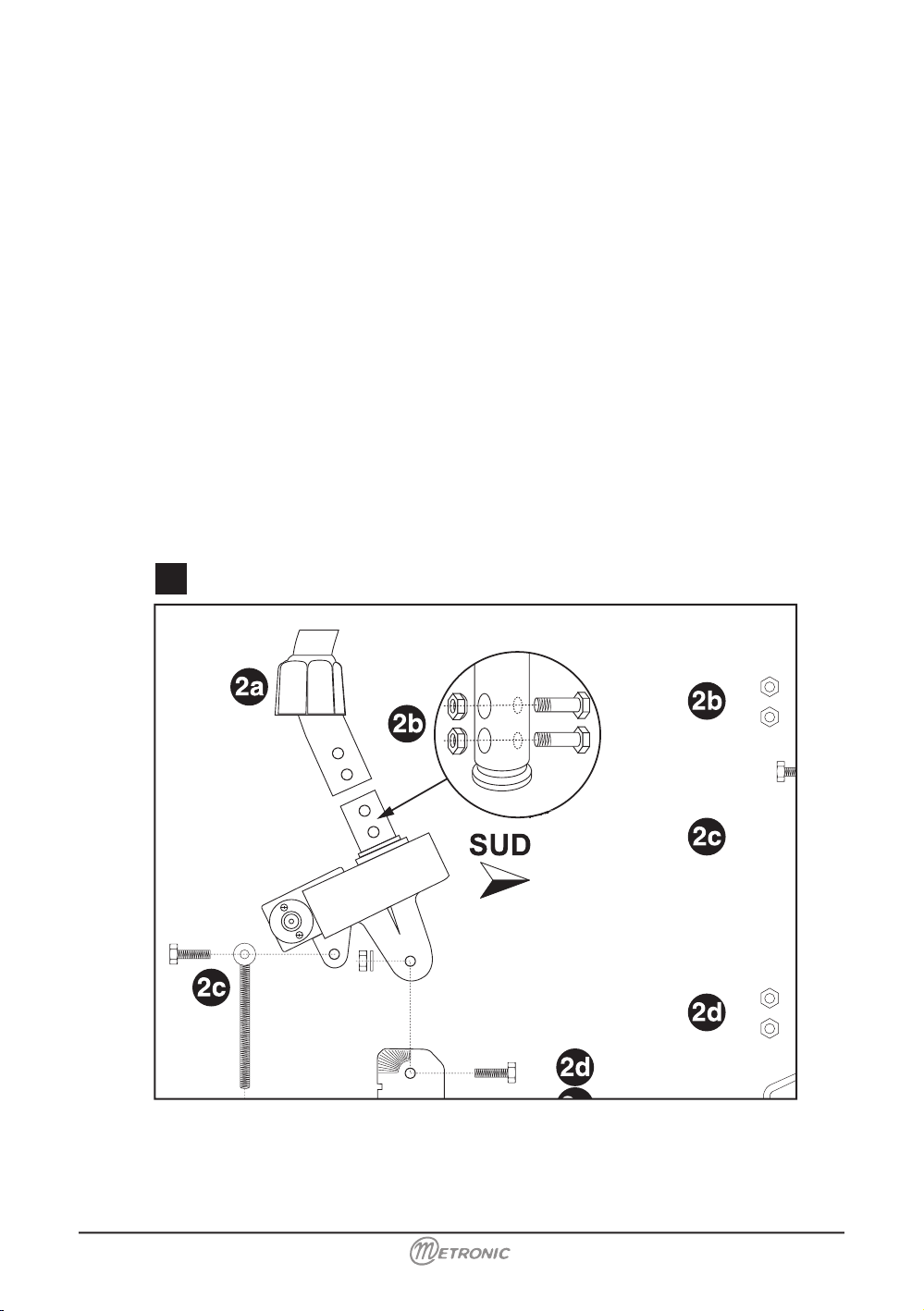
Assembling
• Make sure the fixing (tube or stand off arm) is stable and strictly vertical. An error bigger
than 1 degree (2 cm, or 3/4 inch per meter) from the vertical will preclude the motor for
working properly. If necessary, add some block between the wall and the fixing. Check the
verticality with a spirit level or a plumb line.
• Assemble together the parts of the motor (diagram 2). Put first the U-screws (1) through
the part (2). While assembling the part (2) with the body, pay attention to the washer (3) :
the part labelled «down» must be placed on the bottom, as shown on the picture.
• Once the motor is assembled, do not fix it straight away on the mast or the stand off arm,
some operations needs to be done near the receiver first.
2
www.metronic.com
www.metronic.com
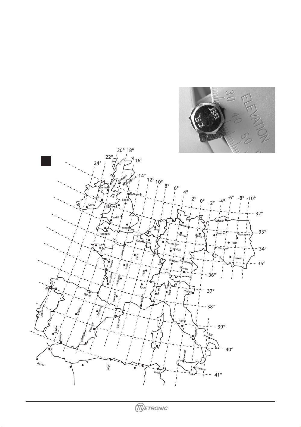
Angle adjustment
Look at the Europe map (diagram 3) and find your elevation angle in relation to the horizontal
line. For example, about 31,5° for Glasgow, 38° for Bordeaux and 39,5° for Napoli, 34,5° for
Brussels.
When the right angle as been adjusted, tighten the screws.
Be sure to read the angle on the side labelled «ELEVATION», not on the side labelled
«LATITUDE»
Inclination and angular reading for Hotbird 3
Example for Brussels
3

www.metronic.com
D - Connection
For the installation you will need 2 pieces of cable. The first one, roughly 1,5m (5ft) to go from
the LNB to the motor, the second one as long as it takes to go from the motor to the receiver.
Prepare the cables and assemble the “F” plug at the end of the cable.
Respect the dimension indicated on the diagram 4; the plug must screw on the aluminium foil
rolled up on the outer sheath. Make sure that none of the braid strand is in contact with the
central core of the cable.
Connect the receiver to the television set with a scart lead. Put the motor near the receiver,
on a table or on the floor, and connect the receiver LNB input to the Motor RECEIVER output
with the 1,5m (5ft) cable, then switch on the receiver.
4
M
oteur Horizon-Horizon
R
5
E - Reset the motor and checking of the stop
The reset of the motor is to reset its position, and put it at 0°, which means face south.
Go into the DiSEqC 1.2
(2)
menu and then reset the motor
(3)
.
• The motor will reset while looking for his reference position. If the motor does not turn,
connect the motor to the LNB with the long cable then reset the motor.
(2)(3)
Go to corresponding paragraph page 13

www.metronic.com
www.metronic.com
F - Prepare the motor
You will now store the position of Hot Bird then put back the motor precisely at 0° to assemble
the satellite dish.
1) Put the receiver on the Hotbird reference channel
(1)
.
2) Give a number to the Hotbird satellite
(6)
(in any doubt put 4), and then wait that the motor
stops turning.
3) Look on the map of Europe (3) and find your Hotbird angular reading in relation to the
vertical lines. For example, 18° E in Glasgow, 15° E in Bordeaux, and 2°W in Napoli.
4) Go into the DiSEqC 1.2
(2)
menu then, with a continuing rotation
(4)
, bring the motor roughly
on the Hotbird azimuth with a step by step rotation
(5)
.
Example: London = 14°
With the remote control you must make the motor turn until the metallic notch used to read
the azimuth reaches 14°. See example on the picture 6.
When the arrow is on the right hand side of the 0, the motor turns the dish to the East.
5) Store the Hotbird position
(7)
6) Reset
(3)
the motor to bring it back to the 0° position.
7) Switch off the receiver, take off the cables and then fix the motor on the wall mount or
mast. Tighten the screws (4) with such a torque that it doesn’t fall down, but to still allow
to turn around the mast.
8) Direct roughly the motor towards the south. In case of an assembling on a wall, make
sure the wall faces south (+/- 20%).
9) Link the receiver and the motor with the long wire prepared at the step D.
6
Exemple for London
(1)(2)(3)(4)(5)(6)(7)
Go to corresponding paragraph page 13

www.metronic.com
G - Satellite dish assembling
Assemble the different parts of the satellite dish (see the user manual included with it).
H - Assemble the satellite dish on the motor
• Assemble the satellite dish and fix it on the motor’s stem. The satellite dish U-Bolt must
be as low as possible on the stem. As the motor is at 0°, make sure you perfectly align the
dish offset arm with the motor (diagram H1). In order to prevent the dish from falling down
in case of breakdown of the U-screw of the dish, we advise you to put the security-bolt
(marked 4 on the figure page
15). If this bolt is to short to maintain the U-screw, link it to
the dish with the help of a strong wire.
• Direct approximately the whole set(satellite dish + rotor) towards the south. Adjust the
angle on the back support of the dish, so that the dish is vertical.
• Switch on the receiver.
• Do a continuing rotation
(4)
until the stop 75° East and 75° West to check if there is no
obstacle. If you get close from an obstacle during the rotation, go to paragraph N page 24
to adjust your electronic limits.
• Put the receiver on the Hotbird reference channel.
H1
North
H2
South
OK
WRONG
(4)
Go to corresponding paragraph page 13

20
www.metronic.com
www.metronic.com
K - Alignment / Satellite dish orientation
• At the end of the step K, you will receive the Hotbird reference channel on the television
screen. Do not go to step L (adjusting the alignment) if you do not receive this channel.
1) Put the receiver on the Hotbird reference channel then display the signal indicator
(8)
.
2) While checking the level, sweep slowly (for 20 seconds) a quarter of a turn on the right,
then a quarter of a turn on the left while pivoting the whole (satellite dish + rotor) around
the mast. If the level is not going up, increase the satellite dish incline of 2° and do the
same manual scan. Carry on as above by steps of 2° followed by a sweep until the level
increase. When you are on the right satellite, the image will appear in the background.
Adjust it to obtain the maximum level and quality (bar as long as possible). In some area,
it is normal that you will turn up to 20 sweeps, be patient.
3) Block temporally all the nuts.
I - Assembling the LNB head
Check the LNB and receiver user manual.
J - Checking
Before going to the final stage (the alignment) check that your installation looks like the
picture below (exept the cables).
J
(8)
Go to corresponding paragraph page 13

www.metronic.com
L - Orientation adjustment
• Put the receiver on the Atlantic Bird 3 reference
(1)
channel. This satellite doesn’t
broadcast popular or interesting channels. However, its position in the sky makes it an
interesting one for dish and motor alignment.
• Check in diagram the Atlantic Bird 3 angular reading of your geographical area.
• Give
(6)
a satellite number to Atlantic Bird 3 (put 01 in case of hesitation).
• If the motor does not stop at the right value, bring it with a continuing research
(4)
or step
by step
(5)
.
• Store
(7)
this position for Atlantic Bird 3. Exemple : Edingburg = 2°W
Leave all the menus and check that you correctly receive the Atlantic Bird 3 reference
channel
(3)
. If it is not the case, you have 2 cases:
First case: You do not receive anything at all, even when you slightly move the satellite dish
alignment. In that case, it means that a big error has been made during the installation (mast
not vertical, error between east and West, bad reading of the angle…). Restart the installation
from scratch while checking each detail very carefully.
(1)(3)(4)(5)(6)(7)
Go to corresponding paragraph page 13

www.metronic.com
www.metronic.com
Angular reading for Atlantic Bird 3
Second case: You have a bad reception and you have to adjust slightly the satellite dish
position angle (1 or 2 degrees) to receive correctly Atlantic Bird 3. In that case, the design
curve of the motor is out of line with the real curve. We then advise you to go back to the step
K while putting 2° more for the Hotbird position in your area. If the result is not good, try 2°
less.

23
www.metronic.com
M - Validation of the satellites
For each satellite, you have now to storethe right position in the motor. The operation is done
for Hotbird and Atlantic Bird 3, you have to do it for Astra, etc.
Example for Astra 19° E
• Go onto the Astra reference channel.
• Go into the DiSEqC 1.2
(2)
menu and give a number
(6)
to Astra 19°E (03 if you hesitate).
• By a continuous rotation
(4)
and then a step by step rotation
(5)
, make the motor turn to
obtain the maximum level and quality.
• Store
(7)
the position founded.
• Check that you receive the Astra channel. If not, it means that you stored the position
of another satellite, which broadcasts some channels at the same frequency. Try the
operation above again and make sure that your satellite dish is pointed slightly on the left
from Hotbird like shown on the Diagram 17. Do the same operations for the other satellites.
When you receive all the satellites, screw definitively all the nuts. Your installation is
finished.
Note: The Hispasat or Turksat reception with a motorised installation is very difficult and
needs a perfect alignment. For the reception of this satellite, we advise a fixed
Arabsat
Turksat
Astra 28
(Astra 2)
Astra 19
(Astra 1)
Eutelsat W2
Hotbird
Eutelsat W1
Eutelsat W3
Atlantic Bird 3
Hispasat
17
Your motor has got mechanical limits that preclude from moving too far east or west (maximum +/- 75 degrees roughly). These mechanical limits are not adjustable. If ever you put
the motor in a location where there is a risk for the dish to hit an obstacle, then you must set
electronic limit. See the user manual of your satellite receiver for such settings.
(2)(4)(5)(6)(7)
Go to corresponding paragraph page 13

www.metronic.com
www.metronic.com
Electronic stops adjustment (with DiSEqC 1.2 motor)
This paragraph explain you how to reset your motor electronic stops in case you need to do
it.
• Go into MENU / Installation / Channel Setup / Dish Position press OK.
• On the line Limit set, choose disable with the arrows 34 and press on OK.
• Enter you PIN code (0000 at output of factory)
• Check that the line Auto stop indicates off.
• Go onto the line continuously moving and press on 4 to bring the motor at the maximum
to the west.
• On the line limit set, choose West limit and validate by OK.
• Go onto the line continuously moving and press on 3 to bring the motor at the maximum
to the east.
• On the line Limit set, choose East Limit and validate by OK.
The receiver being disconnected from power supply, connect directly the LNB to the LNB
receiver input. Connect a scart lead from the television to the receiver TV output scart socket.
For the moment, do not connect any other standard appliance on the receiver DEMO output.
Switch on the television; connect the receiver on the power supply. Press on the key, the
green LED in the front switch on. Check in the list of the pre programmed channels at the end
of the user manual. You can select and visualize the channels of this satellite towards which
you are pointing.
@Notes : if your satellite dish is currently pointed towards Atlantic Bird 3 (ex Telecom
2C = French national analogue channel in Free To Air), you will not have access to any
digital channels. We then advise you to install another satellite dish to keep receiving the
French national channels in analogue and watch others channels in digital.
5 -
Connection on a xed satellite dish already aligned on a satellite

25
www.metronic.com
LNB
DEMO
TV
VCR /
13/18 V
500 mA
S/PDIF
DiSEqC
1.2
6 -
Connexion on a bi-head system Astra 19,2° + Hotbird already aligned
Remarks : this paragraph goes as well for Monoblocs.
Connect the cables and the leads as indicated on the figure below. It is useful to know on which
inputs of the switch the heads Astra and Hotbird are connected. If you do not know it and that
the installation is difficult to reach, test the 2 possible combinations:
Astra on A (or 1) and HotBird on B (or 2) or the opposite.
To program your receiver, follow the instructions from paragraph 3B page 12.
Caution: you should not touch the satellite dish adjustments nor to the switch, it is
only necessary to program your digital receiver.
Tone Burst
TouchBOX2
LNB
DEMO
TV
VCR /
13/18 V
500 mA
S/PDIF
DiSEqC
1.2
schema

26
www.metronic.com
www.metronic.com
Connect the cables and the leads as indicated on the figures below.
When 2 satellite receivers (a digital and an analogue receiver for example) control
the same motor, it is important that each one of them give the same number to a
given satellite. For an easiest installation of your new digital receiver, locate the classification of the satellites used by your analogue receiver.
If your motor and your receiver have never been used before, use the number that you wish
for each satellite.
7 -
Connection on a motorised DiSEqC 1.2 already aligned
LNB
DEMO
TV
VCR /
13/18 V
500 mA
S/PDIF
DiSEqC
1.2
LNB
DEMO
TV
VCR /
13/18 V
500 mA
S/PDIF
DiSEqC
1.2
figure 5
OU
If you do not have an analogue demodulator, connect directly the receiver to the television.
TouchBOX2
Arrière
Analogique
TouchBOX2
Arrière
Analogique
For each satellite you want to receive in digital, it is necessary to proceed as follows:
Example on HotBird
• Go in MENU / Installation / Antenna type.
• On the line LNB dish, choose Moved with the key 34

www.metronic.com
For each satellite, you will go onto the reference channel (see table 1 page 9) then give a
number to this satellite. For that:
• Go into MENU / Installation / Channel Setup
• On the line Satellite Number, choose the number with the arrows 34. If the number that
you are giving is already taken, an alert message is appearing 3 seconds at the bottom of
the screen.
• Press on OK to give a number to a satellite and then wait until the motor stops moving.
• If your motor was correctly aligned, and that you have entered the right number for
HotBird, the signal indicator must be green. If it is not the case, check the alignment and
your satellite numeration with your analogue receiver, if you have one.
• Press on EXIT to leave all the menus and check that you effectively receive the channel
from the satellite in question.
• Do the same thing for the other satellites.

28
www.metronic.com
www.metronic.com
Digital keys. In normal use, it allows to type the channel
number desired. In the programming mode, that allows to
enter the digital values.
Touch ON / OFF. Allows switching on or switching off and
putting the terminal in standby.
MENU Key. Allow you to enter in the main menu or to leave
the main menus.
3VOL4 key makes it possible to regulate the volume on
a normal use. In the menu, allow you to modify various
parameters.Gives you the ability, as well, to display the
following page (4) or the preceding page (3) in the long list.
6CH5 keys. In normal use, a press on one of the keys
change channel. In the menus, allow you to pass from one
line to another.
OK key. Allow you to display the channels. Validation in the
menus.
EXIT key. Allow you to go back to the preceding menu.
EPG key (Electronic Program Guide). Show the program in
progress and the following ones, when the channels transmit
this information. Press on OK to select the channel or the
emission you would like to watch.
Lang Key. When several audio ways are transmitted (Euronews
on Hot Bird for example) it makes it possible to choose the
language of the broadcast.
Unused key on the TouchBox 2 model.
MUTE Key. A first press makes it possible to switch off the
sound. A second press returns in normal mode.
PRE Key. To go to the preceding channel, the one you were
just watching. Allow you, as well, to switch from one page to
another in the long list.
FAV Key. To access your favourite channels.
PAUSE Key. Allow you to do pause on an image. Another press allow you to go back to the emission.
INFO Key, display technical information on the channel in progress. Allow you, as well, to switch from
one page to another in the long list.
SAT Key, to display the channel list from one satellite.
TV/AV Key, to release the television commutation. You can then watch the normal channel on your
television, while recording another one on satellite.
TXT to deactivate the teletext.
AUDIO Key to switch from the normal mode (stereo) to the mode mono-right or mono-left.
TV/RADIO Key to switch from TV mode to RADIO and opposite.
1
2
3
4
5
6
7
8
9
10
11
12
13
14
15
16
17
18
19
20
8 -
Remote control description

29
www.metronic.com
Infrared cell (detects the remote control infra-red signal).
Signal Indicator. Switch on if the reception is good.
ON / OFF Key. Green when the receiver is on, switch off otherwise.
LNB entry to connect the input lead of the satellite.
LNB output, DEMO, to connect a demodulator or a digital receiver.
Radio mode Indicator (switch off if you watch the television).
Input / output VCR scart. When you play a cassette, the VCR take over automatically on
the receiver. You can use this scart socket to connect an analogical demodulator.
TV scart socket. To connect the receiver to the television TV/Radio Key.
RS232 connector for SAV only.
Power Supply.
Digital audio output, Is active only for the channels, which emit in digital sound (very
rare).
Analogue audio output for direct connection to your HI-FI system.
LNB
DEMO
TV
VCR /
B
SIGNAL
C
13/18 V
500 mA
S/PDIF
DiSEqC
1.2
G
E D
F
K1
LNB
DEMO
TV
VCR /
13/18 V
500 mA
RCA
DiSEqC
1.2
G
E D
F
K2
A
B
C
D
E
F
K1
G
H
I
9 -
Receiver description
version
version
K2

www.metronic.com
www.metronic.com
In normal use, you will use only the following keys whose function is described in the following paragraph:
• 34 Keys to regulate the volume of sound.
• 65 Keys to change channels
• Key to switch off and switch on the sound.
• Digital Keys to go directly to a channel
• EPG Key to reach the programs guide.
• OK Key to access a TV channel or a radio.
At output of factory (and after a reset), the
56 keys allow me to change some channels
among the list of the pre-programmed channels. You can also access directly a channel
while entering its number.
By pressing on OK you will make the TV channel list to appear.
10 -
Day to day use
11 -
Access a channel

www.metronic.com
12 - Add a channel
You can either add a particular channel, of which you know the technical features (manual
search), or add a new unknown channel (automatic search).
A - Manual search
A channel is emitted by what is called a transponder (TP). It is a satellite relay of which you
should known the 4 following parameters:
• Its frequency (e.g. 12551 MHz).
• Its debit of symbol SR (e.g. 22000)
• Its polarity (e.g. Vertical)
• The satellite which emits it (e.g. Astra 19.2).
You will find these parameters in specialized magazines, which propose a monthly update,
or on www.satcodx.com, www.lyngsat.com , etc.)
• Go into MENU / Installation / Channel setup
• On the Satellite line, press on OK to display the satellite list.
• With the 5CH6keys, select the satellite, which emits the channel to be added, then press
on OK.
• Go onto the line Frequency and type OK to display the list of transponders.
• With the 56 keys, select the transponder (TP) which emit the channel to add and type OK.
If the TP does not appear in the list, add it as described in the paragraph 12C page 32.
• Check that the quality indicator is green. If it is not the case, that means the TP parameters
are incorrect, that the LNB properties are false or that the satellite dish is not aligned on the
right satellite.
• On the line SCAN MODE, display FTA only with the key 34.
Note: your receiver can only receive the channel in clear (FTA), but some channels in
clear are sometimes declared as encrypted by the broadcaster. To add these channels,
select all.
• On the line Network search, display off thanks to the keys34. If you select On, the
search will wider to all the frequencies transmitted by the broadcaster.
• Press onto the green key (TP Scan) to launch the search. A confirmation window will
appears: type EXIT.
@Note: the EXIT key adds at the end of the list the new channels from the transponder.
The channels already in memory will not be affected. If you type OK, the channels already
in memory will be deleted, then all the channels from the selected transponder will be put
at the end of the list.
• The window Program Search opens, the list of channel found appears then the receiver
goes back into the Menu Channel Setup. Press 3 times on EXIT to leave all the menus.

www.metronic.com
www.metronic.com
B - Automatic channel search
• Go into MENU / Installation / Channel Setup
• Go onto Satellite, press on OK to display the
satellites list.
• With the 5CH6 keys, selecte the satellite, which
emits the channel to be added, then press on
OK.
• Press on the blue key (Sat scan).
• Press on EXIT to launch the search while adding
all the new channels at the end of the channel
list.
• The window search program appears and
display all the channels found.
@Note: The automatic search (Sat scan) sweeps the transponders list associated to the
satellite. If a channel is not found, and you are sure that it exists, it may be because you need
to update the transponders list. (see following paragraph)
C - Add / Delete / Edit a transponder
• Go into MENU / Installation / Channel Setup
• Press OK on the Satellite line to display the satellites list.
• Choose the satellite with the 34 keys and validate by OK.
• Go onto the line Frequency and type OK to display the transponders’ list.
To delete a transponder
• Go onto the transponder to delete with the keys 56 then press on the yellow key. Confirm
by OK. Note: deleting the obsolete transponder accelerate the channel automatic search.
To add a transponder
• Press on the blue key (add).
• Enter the 5 figures of the frequency 4
• Selectthe polarity (H/V) with the 6 key then press
on4
• Press the 5 debit figures (SR) and the (save).
• Press on OK to leave the transporters’ list.

www.metronic.com
D - Particular channel search (PID)
In some cases (rare) a manual or automatic search could not find a channel that effectively exists.
You should then add it with its “PID” which you will find in the specialized magazines or specialised
website.
• Go into in MENU / Installation / Channel setup
• Onto Satellite, press on OK to display the satellites
list.
• With the 5 CH 6 keys, select the satellite, which
emits the channel, to be added then press on OK.
• Go onto FREQUENCY, type OK to display the
transponders list.
• Go onto the TP where the channel to add is and
validate by OK. If the TP is not in the list, add it (see
preceding paragraph).
• Press onto the yellow key to display the data entry
window PID.
• Enter the Video PID onto the line V-PID, the PID
audio onto the line A-PID and the PID PCR onto the
line P-PID. Note, the PID PCR is very often equal to the video PID.
• The new channel is now added at the end of the list under the name “TV CH”. You then have
to rename it by following the explications from the paragraph 13E page 35.
E - Add a satellite
If the channel is emitted by a satellite which is not factory pre-programmed, you have to create the
satellite before researching the channel. For that:
• Go into MENU / Installation / Channel Setup
• Type OK on the line satellite to display the satellite
list.
• Scroll down with the key 6 on the line which follows
the last satellite.
• Press onto the blue key to give a name to the
satellite (see paragraph 13E page 35).
• If you are in a motorised reception, give a free
number on the line Satellite number. If you are in
commuted reception, choose the right LNB on the
LNB line. (see § 3 B page 12).
• Scroll down onto the line Frequency and type OK to
display the transponder’s list.
• Add the necessary TP as indicated in the paragraph 12C page 32.

www.metronic.com
www.metronic.com
Whatever if it is the TV list or the radios list, you can move a channel, remove it, rename it, mask it or
block it. A masked channel is not accessible with the 5CH6 keys. A blocked channel requires a PIN code
to be watched. You can also sort the channel list according to some criteria. To personalize the television
channel list, go into MENU / Channel organizer.
Before modifying a channel, you could pre-watch it by selecting it with
5 CH6 keys then by typing
on OK.
At any time, you can:
A - Delete one or several channels
• Press on the yellow key
• Select the channel to delete with keys 56.
• Press onto the red key, a ticked box appears on the line
• You can select some other channels and tick it with the red key.
• When your selection is finished, press several times on EXIT to leave all the menus.
B - Delete all the channels
• Press onto the yellow key then onto the blue key
• Confirm by OK then enter the PIN code (0000 at output of factory)
• Press several times on EXIT to leave all the menus.
C - Move the channels
• Go onto the channels to move with the keys 56
• Press onto the red key then the yellow key
• Type the location number you want for this channel
• You can move some other channels the same way before leaving.
• When your reorganisation is finished, press on EXIT, on OK, then enter the PIN code.
D - Hide channels
A hidden channel is a channel which does not appears in the channel list. You could if you want to get
it back in the future.
• Go onto the channels to hide with the keys 56.
• Press onto the green key then onto the blue key.
• You can hide some other channels the same way before leaving.
• When your selection is finished, press on EXIT. The hidden channels will now appear with a blue arrow
in the edition channel list. To undo the hiding, use the same way as you do to hide.
13 - Modify / Organise channels / Running the favorites

www.metronic.com
E - Rename a channel
• Go onto the channels to rename with the keys 56.
• Press onto the green key the keyboard appears. The initial name appears in the top window,
surrounded by green.
• Place the cursor under the letter you want to modify.
@Note: the INFO key delete the letter above the cursor, the Key PRE erase totally
the name.
• Press on 6 to activate the keyboard and select the letters by OK.
• When your selection is over scroll up into the windows name with the key 5 (green window) and
validate by OK.
Some channels, even emitted in clear (without subscription) are reserved for
an adult public. To preserve your children, we advise you to install a parental
Pin code and block these channels (see paragraph 14E).
F - Lock a channel
A locked channel asked the PIN code to be watched.
• Go onto the channel to lock with the keys 56.
• Press onto the green key then onto the red key.
• Type the PIN code (0000 at output of factory), a lock appears.
• You can lock other channels, the same way, before leaving.
• When you selection is finished, press on EXIT.
G - Sort channels
Press onto the red key then
• Onto the red key for an alphabetical sort
• Onto the blue key for a sort by type (clear / encrypted)
• Onto the green key for a sort by satellite
Press on EXIT, on OK then enter the PIN code (0000 at output of factory).
H - Favorites channels
You can manage 4 favorites channel lists.
• Press onto the blue key to enter in the favourite channel selection mode.
• Go onto the channel to be selected with the arrows, and then press on the colour key
corresponding to the list you want.
• A heart with the colour in question appears following the channel name.
@Note: A channel could be put in several favourite lists at the same time. A heart
appears for each list.
• When your selection is finished, press on EXIT.
To access the favourite channel list, simply press on the FAV key. Several following press
will scroll the 4 lists.

www.metronic.com
www.metronic.com
A - Choice of language
To choose the language of the menus, press on the remote control key MENU, select the 4th
line and press on OK. Select again the 4th line and press OK. Select the 1st line and press
on OK then select the language you want with keys 34.
Press 4 times on EXIT to leave all the menus.
Some channels broadcast in several languages or emit some sub-titles in several languages
(very rare). You could choose the language by default in the Menu / Installation / System
setup / Language settings
.
B - TV scart adjustment
In MENU / Installation / System setup / TV settings, you could adjust the picture which
going to the television
• On the line TV Mode, leave Auto. You could however force the SECAM mode if your
television is not compatible with PAL.
• On the line Screen mode, choose 4:3 LetterBox if you have a normal television, 16:9 if
you have a 16:9 television.
• On the line CVBS/ RGB, the mode by default is CVBS (standard mode which always
work). But you can use the
RGB mode, which gives a better picture if your television is
compatible.
The lines UHF Mode and UHF channel are not used in the TouchBox2.
C - Time setting
The time setting is necessary if you want to use the timer (programmed switching on to record
pre-recorded program).
Into MENU / Installation / System setup / Time settings, you can set up the time manually
or automatically. For an automatic adjustment, choose On on the line GMT usage. You then
have to adjust the time difference, which is in the UK and in the Republic of Ireland GMT+0.
Some channel emits a false time. He might be useful to adjust manually the system. On the
line GMT usage, choose Off then adjust manually the time on the line Set local time and the
date on the line Set date.
@Note: it is common that the time displayed by the channel is wrong. It is the
“normal” that when you change channel the system time change. Metronic cannot
guarantee the exact time displayed on its receiver.
14 - Miscellaneous adjustment

www.metronic.com
D - Programming of recording
You can program an automatic switch on and switch off of the receiver, for example, to record
a later time program.
In the main menu, the menu Timer menu allows you to program up to 8 later time
recordings.
• On the line Timer state, choose Enable.
• On the line Timer Mode, choose Power On.
• On the line Timer cycle, choose One Time for one off recording. You could repeat it, as
well, everyday (Every Day) or every week (Every Week
).
• On the line Date, adjust the event time,
• On the line Time, adjust the time of start
• On the line Ending Time, adjust the time of the end of the program,
• On the line Channel, press on OK to display the channel list. Choose then the channel to
record with the arrow then validate by OK.
• Press on Menu to record the adjustment and come back to the main menu.
@Note: Take a sufficient margin concerning the starting time. The time of the system
is not effectively, very accurate, and varies very often when you change channels.
Advice: Switch off your television with button ON/OFF to avoid it to switch on when the
timer will start.

www.metronic.com
www.metronic.com
E - Parental control
To block some channels, go to the paragraph 13 F page 35
To make your protection efficient, you need to change the PIN code at lock access to
menus:
• Go into MENU / Installation / Parental lock, adjust lock on the line Installation
• On the line Old PIN type the 4 figures of the actual code (0000 at output of factory)
• On the line New PIN, type the 4 figures of your new code.
• Enter again these 4 new figures on the line Verify PIN.
• Your new code is automatically saved, keep it preciously.
This operation put back in memory the factory parameters, as well as the channel list.
Be careful, all the modifications you carried out will be lost (new channels, favourite
channels…)
To reset the receiver, do the followings:
• Go into MENU / Installation / System setup / Factory reset
• Type the PIN code (0000 at output of factory) and patient.
The figure 6 page 39 proposes two connexions among all the possible configurations. The
figure 6a is an assembly in cascade. It leaves space for a possible decoder for Pay per View
channels, but does not allow you to record the analogue channels.
The figure 6b show a star assembly. It allows you to record analogue, but does not work
with all the analogue receiver. It is a solution (which requires a scart to scart adaptor), which
consists in connecting the video cassette recorder and the digital receiver on the analogue
receiver VCR scart input.
To record the digital channels, it is necessary that the receiver is switch on the channel to
record. Then launch the recording on the video cassette recorder channel A/V. To read a
cassette, simply launch the reading, the video cassette recorder will automatically take the
hand on the receiver. If it is not the case, press on remote control TV/VCR key of your video
cassette recorder.
15 - Reset the receiver
16 - Connection with an analogue receiver and video
cassette recorder

www.metronic.com
LNB
DEMO
TV
VCR /
13/18 V
500 mA
S/PDIF
DiSEqC
1.2
LNB
DEMO
TV
VCR /
13/18 V
500 mA
S/PDIF
DiSEqC
1.2
Figure 6
Connect simply your video cassette recorder on the receiver VCR scart input. To record the
digital, it is necessary that the receiver is switch on the channel to record. Then launch the
recording on the video cassette recorder AV channels (0, AV, EXT....) see the video cassette
recorder user manual for exact handling.
To read a cassette, launch simply the reading, the video cassette recorder will automatically take
the hand on the receiver. If it is not the case, press on the remote control TV/VCR key of your
video cassette recorder.
• The screen displays «No signal or Bad signal»
Three possibilities:
1. The program (channel) that you wish to watch has disappeared from the transponder. Get a
specialized magazine to know if the parameters of these channels have changed or if she has
disappeared.
2. You are on another satellite, which emits channels on the same frequency as the one you
would like to watch.
3. The motor work and the satellite dish spin, wait until it’s finished.
17 - Use with a VCR
18 - In case of problem
VCR back
TouchBOX2
Analogue back

40
www.metronic.com
www.metronic.com
• On one or more channels, the screen remains black.
The channel you want to watch is probably scrambled. For your information, an operator can
emit a channel scrambled with information making believe to the receiver that is a free to air
channel. The opposite is possible. `
Be careful: A channel could be free to air sometimes during the day.
• The terminal asks me a PIN code to watch a channel
Enter 0000 if you did not input a PIN code. If you input a PIN code, but you forgotten it, reset
the receiver, contact the hotline.
• My motor spin but does not go beyond a certain angle.
See paragraph 19 (below).

www.metronic.com
Name:
Address:
Postal Code:
City:
Tel.
• Do you already have an installation satellite? yes no
If yes, which made?
• Product bought:
Fixed Digital kit
Motorised digital kit
Digital receiver alone
• Reason of purchase :
Access to digital quality
More channel choice
Foreign channels
• How did you know METRONIC ?
Friends / parents
Advertising / catalogues
In store
I have already a METRONIC receiver
• Did you already use the METRONIC help line ?
yes no
If yes, what do you think about it ?
In the event of a complete kit purchase:
• Did you install it yourself ? yes no
• Did you go through a fitter ?
yes no
If yes, for which amount ?
• Which difficulties did you encounter at the time of the installation ?
1 Assembly of the plug on the cable Easy Difficult
2 Satellite dish assembly Easy Difficult
3 Heads (LNBs) assembly Easy Difficult
4 Motor assembly Easy Difficult
(in the event of motorized kit)
6 Alignment Easy Difficult
Date of purchase :
Place of purchase :
Name of the shop :
QUESTIONNAIRE QUALITY
TouchBOX2
Send to : IT4E – 30, Heathfield Court – London W4 4LR

www.metronic.com
www.metronic.com
• Did you isolate the LNBs (heads) ? yes no
METRONIC isolated paste
Other products METRONIC
Silicone adhesive tape
Ruban adhésif
Other.............
• Do you think the user manual is user friendly when you have to install, without an installer, a satellite kit?
yes no
Which modifications would you wish to see?
• Where did you install your satellite kit ?
On a balcony
On the roof (chimney...)
On the wall
On the ground
Other.............
• Which cable lenght did you use ?
05 m
10 m
15 m
20 m
30 m
40 m
more
Other remarks or suggestions :
• Or you satisfied of your purchase ?
yes no

43
www.metronic.com
You will find in the following pages, the channels characteristics that we programmed
in the receiver. This programming was established according to information’s, which are at our
disposal to date, and according to programs’ which are emitted to date.
The operators responsible for the television broadcasts by satellites sometimes change
without notice the frequencies and the transponders; we cannot unfortunately guarantee the
accuracy of these programming in time, please accept our apologies on this matter. You will
be able to ameliorate these factory adjustments if you follow the instructions given on §12
page 31.
In spite the care that we brought to the design of our products and the drafting of this
user manual, you may have encountered problems.
Please do not hesitate to contact us, our specialists are at your disposal to advise you free of
charge except the call cost :
You can contact us by e-mail :
hotline@metronic.com
IMPORTANT : in the object of your message, make sure the word METRONIC appears.
Phone number : 0033 (0)892 350 315
Monday to friday, from 9:00 to 12:00 am and from 2:00 to 7:00 pm (french hour)
B
EFORE CALLING make sure you have the followings:
• Receiver Model: TouchBox 2
• Satellite received :
In a constant preoccupation to improve our products, could you please send us back the quality questionnaire
(postage refunded on request). If you send us back the questionnaire, it gives you 3 months of additional guarantee
(parts only).
CERTIFICATE OF GUARANTEE
The TouchBox 2 receiver is guaranteed one year parts and labour. In the event of
a breakdown, the transport charges outward are the customer responsibility; the costs
carriage back is our responsibility.
To be valid, the certificate of guarantee must duly be filled and send back with the
invoice photocopy or the sales slip.
Réf. du matériel: TouchBOX2
Date of purchase: Serial number:
Address : SAV Métronic, BP 56, La Tombe, 37320 Esvres sur Indre, FRANCE
email: hotline@metronic.com
ASSISTANCE AND ADVICE

www.metronic.com
www.metronic.com
Hotbird---------------------------------------------------------------
1 RAI1 11766 V 27500
2 RAI2 11766 V 27500
3 RAI3 11766 V 27500
4 Retequattro 11919 V 27500
5 Canale 5 11919 V 27500
6 Italia 1 11919 V 27500
7 RaiMed 11766 V 27500
8 Rai Edu1 11804 V 27500
9 RaiEdu2 11766 V 27500
10 RaiUtile 11804 V 27500
11 RaiSportSat 11804 V 27500
12 RaiNotizie24 11804 V 27500
13 RaiDoc 11804 V 27500
14 4fun.TV 10719 V 27500
15 EWTN 10723 H 29900
16 Geo TV 10723 H 29900
17 Sony 10723 H 29900
18 Mediatel 10949 V 27500
19 Tele Lumiere 10949 V 27500
20 MTA INTL 10723 H 29900
21 Sun KTV 10949 V 27500
22 Maharishi 10949 V 27500
23 Vectone Urdu 10949 V 27500
24 Vectone Bangla 10949 V 27500
25 Sun TV 10949 V 27500
26 Casino Channel 10949 V 27500
27 Vectone Tamil 10949 V 27500
28 Vectone Hindi 10949 V 27500
29 TRT INT 10957 H 04340
30 SKY Prima Fila 10990 V 27500
31 CCTV9 11034 V 27500
32 Euronews france 11034 V 27500
33 God TV 11034 V 27500
34 Beur TV 11034 V 27500
35 RTR-Planet 11034 V 27500
36 TFJ 11034 V 27500
37 VOX CH 11054 H 27500
38 NBC 11054 H 27500
39 ZDF 11054 H 27500
40 RTL Television 11054 H 27500
41 RTL CH 11054 H 27500
42 ARTE GERMAN 1 11060 V 06510
43 ARTE FRENCH 1 11060 V 06510
44 Kurdsat 11096 H 27500
45 CNL New Life Cha 11096 H 27500
46 TV 5 - FBS 11137 H 27500
47 TV 5 Europe 11137 H 27500
48 Roma Uno 11137 H 27500
49 Videolook 11137 H 27500
50 Kurdistan TV 11137 H 27500
51 TBNE 11137 H 27500
52 Videolina 11137 H 27500
53 Telegenova 11137 H 27500
54 RTB 11137 H 27500
55 starMarket 11137 H 27500
56 ELITE SHOPPING 11200 V 27500
57 Sailing Channel 11200 V 27500
58 NOELLO SAT 11200 V 27500
59 CardMania TV 11200 V 27500
60 SuperPippa 11200 V 27500
61 ODEON SAT 11200 V 27500
62 TAXI channel 11200 V 27500
63 TLC SAT 11200 V 27500
64 STARSAT 11200 V 27500
65 PIEMONTE SAT 11200 V 27500
66 ROMA SAT 11200 V 27500
67 AL HAYAT 11200 V 27500
68 PUNTO SAT 11200 V 27500
69 Olisat VV Cont 11304 H 27500
70 Olisat Mundovisi 11304 H 27500
71 Video Mediterran 11304 H 27500
72 Olisat Cubavisio 11304 H 27500
73 TV5 11338 V 05632
74 TVN 11408 V 27500
75 TVN Siedem 11408 V 27500
76 MANGO 24 11408 V 27500
77 TVN METEO 11408 V 27500
78 TVN TURBO 11408 V 27500
79 Polsat 1 11412 H 06198
80 Polsat 2 11412 H 06198
81 DW-TV 11604 H 27500
82 tv.nrw 11604 H 27500
83 VIVA polska 11604 H 27500
84 ARD Das Erste 11604 H 27500
85 RTL 2 CH 11604 H 27500
86 Super RTL CH 11604 H 27500
87 TV ROMANIA 11623 V 27500
88 Chai TV 11623 V 27500
89 102.5 HIT Ch 11623 V 27500
90 CANAL CLUB 11623 V 27500
91 ITALIA CLUB 11623 V 27500
92 123SAT/69XTV 11623 V 27500
93 Bloomberg Europe 11642 H 27500
94 Bloomberg German 11642 H 27500
95 Bloomberg Englis 11642 H 27500
96 Miracle TV 11642 H 27500
97 EDTV 11746 H 27500
98 EDTV SPORT 11746 H 27500
99 EDTV BUSINESS 11746 H 27500
100 PMC 11746 H 27500
101 EDTV DRAMA 11746 H 27500
102 Senato 11766 V 27500
103 TVE INTERNACIONA 11785 H 27500
104 CANAL 24 HORAS 11785 H 27500
105 TVE INTER. ASIA 11785 H 27500
106 RaiNettunoSat1 11804 V 27500
107 RaiNettunoSat2 11804 V 27500
108 Camera Deputati 11804 V 27500
109 SAT2000 11804 V 27500
110 Sport Promo 11843 V 27500
111 HSE 11900 H 27500
112 ORT-I 11938 H 27500
113 DAN SS MUSIC +49 11938 H 27500
114 SKY On Air 11977 H 27500
115 IQRAA - ARABESQU 12015 H 27500
116 MA3 12015 H 27500
117 FUTURE TV - ARAB 12015 H 27500
118 Telesierra 12092 H 27500
119 HB CHANNEL 12111 V 27500
120 ARM 1 12111 V 27500
121 Made In Italy 12111 V 27500
122 Ceramicanda 12111 V 27500
123 AL JAZEERA 12111 V 27500
124 UNOSAT 12111 V 27500
125 Coming Soon TV 12111 V 27500
126 MediterraneoSat 12111 V 27500
127 GAY.TV 12111 V 27500
128 DunaTV 12149 V 27500
CHANNELS GUIDE

45
www.metronic.com
129 TV7 Tunis 12149 V 27500
130 Khabar TV 12149 V 27500
131 ChatGameTV 12149 V 27500
132 TizianaSat 12149 V 27500
133 LIDER TV AZE 12149 V 27500
134 CCTV 12169 H 27500
135 BALKANIA TV 12188 V 27500
136 HIGH TV 12188 V 27500
137 RTS SAT 12188 V 27500
138 TV MAGIC 12188 V 27500
139 O-6 TV 12188 V 27500
140 ERT SAT 12188 V 27500
141 EXTRA TV 12188 V 27500
142 TELEASTY 12188 V 27500
143 MKTV 12188 V 27500
144 FASHION 12245 H 27500
145 ADJARA TV 12245 H 27500
146 DCTV-german 12265 V 27500
147 DCTV-english 12265 V 27500
148 DCTV-italy 12265 V 27500
149 DCTV-turkish 12265 V 27500
150 DCTV-spanish 12265 V 27500
151 DCTV-french 12265 V 27500
152 DCTV-portuguese 12265 V 27500
153 NAPOLI INT. 12303 V 27500
154 MAGIC 12303 V 27500
155 COUNTDOWN 12303 V 27500
156 ITALIAN MUSIC 12303 V 27500
157 OASI.TV 12303 V 27500
158 DANCE TV 12303 V 27500
159 SAT8 12303 V 27500
160 TV Puls 12322 H 27500
161 Info/Teleuniwers 12360 H 27500
162 PilotTV 12360 H 27500
163 Telepace 12380 V 27500
164 Syria Satellite 12380 V 27500
165 SAT 7 12380 V 27500
166 Abu Dhabi TV 12380 V 27500
167 RTV Montenegro 12380 V 27500
168 ASB 12380 V 27500
169 Jordan TV 12380 V 27500
170 SFi 12399 H 27500
171 EbS 12476 H 27500
172 metv 12476 H 27500
173 LibertyTV.com 12476 H 27500
174 2M Maroc 12476 H 27500
175 SET 12520 V 27500
176 SARDEGNA UNO 12520 V 27500
177 ITV 12520 V 27500
178 Jaam E Jam 12520 V 27500
179 TAPESH 12520 V 27500
180 PUGLIA CHANNEL 12520 V 27500
181 IPN 12520 V 27500
182 BENI CULTURALI 12520 V 27500
183 MEDIOLANUM 12540 H 27500
184 Nile TV Internat 12540 H 27500
185 Nile News 12540 H 27500
186 Bulgaria TV 12540 H 27500
187 24ore.tv 12558 V 27500
188 OPENET.TV 12558 V 27500
189 TELE PADRE PIO 12558 V 27500
190 ANN 12597 V 27500
191 EuroNews 12597 V 27500
192 Al Arabiya 12597 V 27500
193 BBC World 12597 V 27500
194 Sharjah 12654 H 27500
195 Qatar 12654 H 27500
196 Saudi 1 12654 H 27500
197 Kuwait 12654 H 27500
198 Libya 12654 H 27500
199 Oman 12654 H 27500
200 ESC 12654 H 27500
201 Iraq 12654 H 27500
202 Al manar 12654 H 27500
203 E-TV 12673 V 27500
204 Emi.Li TV 12673 V 27500
205 Thai TV5 12673 V 27500
206 3ABN 12673 V 27500
207 Tv Moda 12673 V 27500
208 Studio Europa 12673 V 27500
209 Playlist Italia 12673 V 27500
210 Telemarket 12673 V 27500
211 GAME NETWORK 12673 V 27500
212 PASSIONS 12692 H 27500
213 ONYX 12692 H 27500
214 AB SAT PROMO 12692 H 27500
215 SKY TG 24 12713 V 27500
216 Live ShowTV 11623 V 27500
217 SEXY Cine TV 11623 V 27500
218 ULTRA BLUE TV 11623 V 27500
219 Italiasat 12092 H 27500
220 Erotic TV 12092 H 27500
221 SEXY SAT 12245 H 27500
222 PLEASURE TV 12303 V 27500
223 BLU LINE TV 12303 V 27500
224 Xstream 12476 H 27500
Astra19--------------------------------------------------------------
225 TV TRWAM 10833 H 22000
226 Bibel TV 10833 H 22000
227 RAZE TV 10833 H 22000
228 Tango TV 10833 H 22000
229 Al Jazeera 11568 V 22000
230 CANAL ALGERIE 11568 V 22000
231 TV 5 11568 V 22000
232 ESC1 - EGYPT 11568 V 22000
233 RAI 1 11568 V 22000
234 DW-TV 11568 V 22000
235 RTPI 11568 V 22000
236 TV7 11568 V 22000
237 ARTE 11568 V 22000
238 2M Maroc 11568 V 22000
239 DW-TV 11597 V 22000
240 Sky News Intl 11597 V 22000
241 TVEi 11597 V 22000
242 RTM MAROC 11597 V 22000
243 TVC INT. 11686 V 22000
244 ANDALUCÍA TV 11686 V 22000
245 EUSKADI TV 11686 V 22000
246 TM SAT/LAOTRA 11686 V 22000
247 TV GALICIA 11686 V 22000
248 MTV Central 11740 V 27500
249 Travel 11778 V 27500
250 CNN Int. 11778 V 27500
251 EURONEWS 11817 V 27500
252 Das Erste 11837 H 27500
253 Bayerisches FS 11837 H 27500
254 hessen fernsehen 11837 H 27500
255 arte 11837 H 27500
CHANNELS GUIDE

46
www.metronic.com
www.metronic.com
256 SR Fernsehen S? 11837 H 27500
257 WDR Köln 11837 H 27500
258 BR-alpha 11837 H 27500
259 SÜDWEST BW 11837 H 27500
260 Phoenix 11837 H 27500
261 KTO 11895 V 27500
262 ZDF 11954 H 27500
263 ZDFinfokanal 11954 H 27500
264 ZDFdokukanal 11954 H 27500
265 ZDFtheaterkanal 11954 H 27500
266 3sat 11954 H 27500
267 KiKa 11954 H 27500
268 EuroNews 11954 H 27500
269 Eurosport 11954 H 27500
270 ProSieben Schwei 12051 V 27500
271 ProSieben Austri 12051 V 27500
272 Kabel 1 Schweiz 12051 V 27500
273 Kabel 1 Austria 12051 V 27500
274 SAT.1 A 12051 V 27500
275 rbb Berlin 12109 H 27500
276 rbb Brandenburg 12109 H 27500
277 MDR FERNSEHEN 12109 H 27500
278 EinsMuXx 12109 H 27500
279 EinsFestival 12109 H 27500
280 EinsExtra 12109 H 27500
281 SÜDWEST RP 12109 H 27500
282 NDR FS MV 12109 H 27500
283 TV.BERLIN 12148 H 27500
284 lastminute.de 12148 H 27500
285 TV TRAVEL SHOP 12148 H 27500
286 SAT.1-CH 12148 H 27500
287 hollywood †cin 12148 H 27500
288 VIC-TV NET DE1 12148 H 27500
289 GOD Channel 12148 H 27500
290 RTL Televisio 12188 H 27500
291 RTL2 12188 H 27500
292 Super RTL? 12188 H 27500
293 VOX 12188 H 27500
294 RTL Shop 12188 H 27500
295 FRANCE 5 12207 V 27500
296 LCP 12207 V 27500
297 BTV 12226 H 27500
298 MTV2 Pop Channel 12226 H 27500
299 L1MBURG 12226 H 27500
300 RTL Austria 12226 H 27500
301 VOX Austria 12226 H 27500
302 RTL2 Austria 12226 H 27500
303 Super RTL A 12226 H 27500
304 ZIK / XXL 12285 V 27500
305 BBC WORLD 12285 V 27500
306 FASHION-TV 12285 V 27500
307 ProSieben 12480 V 27500
308 KABEL1 12480 V 27500
309 NEUN LIVE Tele 12480 V 27500
310 DSF 12480 V 27500
311 HSE24 12480 V 27500
312 SAT.1 12480 V 27500
313 N24 12480 V 27500
314 TELE 5 12480 V 27500
315 Sonnenklar TV 12480 V 27500
316 RTL TELE Letzebu 12552 V 22000
317 QVC GERMANY 12552 V 22000
318 VIVA PLUS 12552 V 22000
319 Bloomberg TV Ger 12552 V 22000
320 Chamber TV 12552 V 22000
321 BVN 12574 H 22000
322 RTBF SAT 12610 V 22000
323 CNBC Europe 12610 V 22000
324 TV5 Europe 12610 V 22000
325 Club Teleachat 12610 V 22000
326 LibertyTV.com 12610 V 22000
327 TV6 12610 V 22000
328 Wishline 12610 V 22000
329 Bahn TV 12633 H 22000
330 K-TV 12633 H 22000
331 XXP 12633 H 22000
332 rhein main tv 12633 H 22000
333 n-tv 12670 V 22000
334 VIVA 12670 V 22000
335 TW1 12692 H 22000
336 OTTO SHOP 12460 H 27500
Astra 28-------------------------------------------------------------
337 BBC 1 London 10773 H 22000
338 BBC 2 England 10773 H 22000
339 BBC NEWS 24 10773 H 22000
340 ETV 10773 H 22000
341 BBC TES 3 10773 H 22000
342 CBBC Channel 10773 H 22000
343 CBeebies 10773 H 22000
344 BBC 1 NI 10773 H 22000
345 price-drop.tv 11954 H 27500
346 Screenshop 11954 H 27500
347 TV Travelshop 11954 H 27500
348 TV Travelshop 2 11954 H 27500
349 Broadband TV 11954 H 27500
350 Ideal World 12032 H 27500
351 ITV News 12032 H 27500
352 QVC 12032 H 27500
353 QVC TSVNOW 12032 H 27500
354 bid-up.tv 12032 H 27500
355 CNN 12051 V 27500
356 Travel Channel 12051 V 27500
357 Travel Deals 12051 V 27500
358 BBC PARL’MNT 12129 V 27500
359 S4C~ Digidol 12129 V 27500
360 S4C~2 12129 V 27500
361 Vitality 12129 V 27500
362 Create & Craft 12129 V 27500
363 Sky News 12207 V 27500
364 Sky News 12207 V 27500
365 Sky News 12207 V 27500
366 Sky News UK 12207 V 27500
367 Sky News Eire 12207 V 27500
368 STAR News 12284 V 27500
369 Boomerang 12324 V 27500
370 TV SHOP 12344 H 27500
371 Reality TV 12344 H 27500
372 FO2 12344 H 27500
373 Factory Outlet 12344 H 27500
374 TVWarehouse.. 12344 H 27500
375 Shop America 12344 H 27500
376 TV Warehouse 12344 H 27500
377 Shop 24/7 12344 H 27500
378 JML Direct 12344 H 27500
379 Game Network 12344 H 27500
380 YES 12344 H 27500
381 Shop Smart 12344 H 27500
382 Community 12382 H 27500
CHANNELS GUIDE

www.metronic.com
383 UCB TV 12402 V 27500
384 ATN 12402 V 27500
385 Overload 12402 V 27500
386 Teletext Holiday 12422 H 27500
387 Going Places 10920 H 22000
388 PCNE Chinese 11565 V 27500
389 TLM(Browser) 10861 H 22000
390 The Betting Zone 10861 H 22000
391 VOLV4 12012 V 27500
392 BADA4 12012 V 27500
393 NISS4 12012 V 27500
394 TWFR4 12460 H 27500
395 NIPV 12246 V 27500
396 ETV2 10802 H 22000
397 BBC 1 Wales 10802 H 22000
398 BBC 2W 10802 H 22000
399 BBC 1 Scotland 10802 H 22000
400 BBC 2 Scotland 10802 H 22000
401 BBC 2 NI 10802 H 22000
402 T4 DEV-4 10847 V 22000
403 BBC 1 W Mids 10788 V 22000
404 BBC 1 N West 10788 V 22000
405 BBC 1 EYks&L 10788 V 22000
406 BBC 1 Yorks 10788 V 22000
407 BBC 1 E Mids 10788 V 22000
408 BBC 1 East (E) 10788 V 22000
409 ETV5 10788 V 22000
410 BBC 1 West 10817 V 22000
411 BBC 1 S East 10817 V 22000
412 BBC 1 South 10817 V 22000
413 BBC 1 S West 10817 V 22000
414 BBC 1 NE & C 10817 V 22000
415 BBC 1 Oxford 10817 V 22000
416 ETV6 10817 V 22000
417 POP 11426 V 27500
418 The Vault 11426 V 27500
419 nation277 11426 V 27500
420 L!VE TV 11426 V 27500
421 POP Plus 11426 V 27500
422 Simply Home 11488 V 27500
423 Simply Ideas 11488 V 27500
424 Rapture TV 11488 V 27500
425 Simply Shop. 11488 V 27500
426 JobsTV 11488 V 27500
427 GayDateTV 11488 V 27500
428 Chart Show TV 11488 V 27500
429 Open Access 11488 V 27500
430 Classic FM TV 11488 V 27500
431 BestDirect+ 11584 H 27500
432 Best Direct 11584 H 27500
433 Auctionworld 11584 H 27500
434 Dating Channel 11584 H 27500
435 Shop on TV 11546 H 27500
436 Thane Direct 11546 H 27500
437 Shoppingworld 11546 H 27500
438 Stop + Shop 11546 H 27500
439 i Sports TV 11546 H 27500
440 Thomas Cook 11526 V 27500
441 Entertainment 11526 V 27500
442 Motors TV 11526 V 27500
443 SAB TV 11388 H 27500
444 Performance 11388 H 27500
445 channel U 11388 H 27500
446 FO3 11388 H 27500
447 txt me 11388 H 27500
448 ACTV 11388 H 27500
449 Chat Box 11388 H 27500
450 Golf Channel 11388 H 27500
451 E&M TV 11388 H 27500
452 Record TV 11388 H 27500
453 Game In TV 11388 H 27500
454 EDTV1 11642 V 27500
455 EDTV Sport 11642 V 27500
456 EDTV Business 11642 V 27500
457 Vectone Bangla 11642 V 27500
458 VECTONE Urdu 11642 V 27500
459 VECTONE Tamil 11642 V 27500
460 VECTONE India 11642 V 27500
461 Extreme Sports 11680 V 27500
462 EuroNews 11680 V 27500
463 GOD Channel 11680 V 27500
464 GOD REVIVAL 11680 V 27500
465 Life TV 11680 V 27500
466 TBN Europe 11680 V 27500
467 OBE 11680 V 27500
468 HollywoodTV 11680 V 27500
469 GOD 2 11680 V 27500
470 mta-muslim tv 11661 H 27500
471 BEN 11661 H 27500
472 Abu Dhabi TV 11661 H 27500
473 CCTV-9 11661 H 27500
474 TelSell 11623 H 27500
475 Wonderful 11623 H 27500
476 revelation 11623 H 27500
477 Classics TV 11623 H 27500
478 Information TV 11623 H 27500
479 g3w8 11623 H 27500
480 FRIENDLY TV 11623 H 27500
481 Fashion TV 11623 H 27500
AtlanticBird--------------------------------------------------------
482 BRTV 12543 H 27500
483 GCPE 1 12543 H 27500
484 GCPE 2 12543 H 27500
Eutelsat W2--------------------------------------------------------
485 SNAI SAT 12608 H 27500
486 SERVICE 5 12608 H 27500
487 LA7 12630 H 6111
488 MTV ITALIA 12630 H 6111
489 RTK PRISHTINA 12633 V 4883
490 Adjara tv 12675 V 4340
491 TOP CHANNEL 11449 H 16000
Sirius-----------------------------------------------------------------
492 NOVY KANAL 11766 H 27500
493 TET 11766 H 27500
494 ENTER-FILM 11766 H 27500
495 INTER 11766 H 27500
496 ENTER 11766 H 27500
497 TRK UKRAINA 11766 H 27500
498 QVC 12303 H 25547
499 Moscow Open Worl 12380 H 27500
500 RTL9 11370 V 3260
CHANNELS GUIDE

48
www.metronic.com
www.metronic.com
EutelsatW3---------------------------------------------------------
501 TV Polonia 11175 V 27500
502 OCCA 1 W3 11283 V 27500
503 M6 Suisse 11283 V 27500
Hispasat1ABC-----------------------------------------------------
504 SOL PORT 11535 V 24500
505 TV Galicia 11811 V 27500
506 Via Local 11932 H 27500
507 Movida Local 11932 H 27500
508 Max Local 11932 H 27500
509 Canal 7 Tv 11932 H 27500
510 REDE RECORD 11932 H 27500
511 Tu Farmacia Tv 11932 H 27500
512 Popular Tv 11932 H 27500
513 Gigashopping 11932 H 27500
514 Vision Local 11932 H 27500
515 Programação 12012 V 27500
516 ATLAS SERVICIO A 11731 H 28126
517 Canal 4 11731 H 28126
518 NUEVA ERA 11731 H 28126
519 EHS 11731 H 28126
520 TVE INTERNACIONA 12092 V 27500
521 CNBC 12092 V 27500
522 TBN ENLACE 12092 V 27500
Arabast2/3A--------------------------------------------------------
523 Bahrain TV 11747 V 27500
524 Saudi 1 11747 V 27500
525 Kuwait 11747 V 27500
526 Libya 11747 V 27500
527 Sudan 11747 V 27500
528 Saudi 2 11747 V 27500
529 Almajd TV 11747 V 27500
530 Oman 11747 V 27500
531 Eritrea 11747 V 27500
532 Iraq Media 11747 V 27500
533 AlManar 11785 V 27500
534 Future 11785 V 27500
535 LBCI 11785 V 27500
536 Star Academy 11785 V 27500
537 TeleLiban 11785 V 27500
538 NBN 11785 V 27500
539 ALArabiya 11785 V 27500
540 NEW TV 11785 V 27500
541 channel 2 11785 V 27500
542 MBC 11785 V 27500
543 Syria TV 11938 V 27500
544 Yemen TV 11938 V 27500
545 Sharjah tv 11938 V 27500
546 Algeria TV 11938 V 27500
547 Tunisia TV 11938 V 27500
548 Aljazeera TV 11938 V 27500
549 Mauritania TV 11938 V 27500
550 Morocco TV 11938 V 27500
551 Almustakilla 11938 V 27500
552 Jordan TV 11938 V 27500
Turksat1C-----------------------------------------------------------
553 Cine5 11025 V 06510
554 Gala 11025 V 06510
555 Viva 11025 V 06510
556 Supersport 11025 V 06510
557 CNN Turk 11584 V 08800
558 Dream TV 11584 V 08800
559 Euro D 11584 V 08800
560 KANAL 7 11135 V 04444
561 TRT 1 11096 V 27500
562 TRT 2 11096 V 27500
563 TRT INT 11096 V 27500
564 TRT 3 11096 V 27500
565 TRT 4 11096 V 27500
566 Service 1 11129 V 04268
567 www.tgrt.com.tr 11882 V 03400
568 E TV ANTALYA 12705 H 02400
569 BRTK KKTC 10968 V 04557
570 STV 11154 V 04557
571 atv 12633 V 04800
572 yeni tv 12638 V 02200
CHANNELS GUIDE

49
www.metronic.com
DIGITAL RADIOS
Hotbird--------------------------------------------------------------
1 TPS & Vous 10796 V 27500
2 Le Mouv 10796 V 27500
3 France bleu 10796 V 27500
4 France Culture 10796 V 27500
5 France Info 10796 V 27500
6 France Inter 10796 V 27500
7 FIP 10796 V 27500
8 Hector 10796 V 27500
9 France Musiques 10796 V 27500
10 Beur FM 10796 V 27500
11 GAME AVENUE 10796 V 27500
12 Europe 1 10873 V 27500
13 Europe 2 10873 V 27500
14 RFM 10873 V 27500
15 RTL 10873 V 27500
16 NRJ 10873 V 27500
17 Radio Classique 10873 V 27500
18 Chérie FM 10873 V 27500
19 Fun Radio 10873 V 27500
20 RTL 2 10873 V 27500
21 RMC 10873 V 27500
22 Rire&Chansons 10873 V 27500
23 MFM 10873 V 27500
24 Nostalgie 10873 V 27500
25 HITWEST 10873 V 27500
26 GUIDE 10873 V 27500
27 BANDIAGARA 10873 V 27500
28 Jazz Moderne 10911 V 27500
29 Jazz 10911 V 27500
30 Blues 10911 V 27500
31 Relaxation 10911 V 27500
32 Contemporain 10911 V 27500
33 Opéra 10911 V 27500
34 Baroque 10911 V 27500
35 Symphonies 10911 V 27500
36 Grand Classique 10911 V 27500
37 Les Tubes Fran? 10911 V 27500
38 RFI 10911 V 27500
39 Skyrock 10911 V 27500
40 Radio Courtoisie 10911 V 27500
41 Contact FM 10911 V 27500
42 Zi-One 10911 V 27500
43 BFM 10911 V 27500
44 PLAYIN TV 10911 V 27500
45 Météo Express 10911 V 27500
Astra19--------------------------------------------------------------
46 CSAT RADIOS 12207 V 27500
47 CANALSAT RADIOS 12207 V 27500
48 RADIOS 2 12207 V 27500
49 RADIOS 3 12207 V 27500
50 RF 12207 V 27500
51 FRANCE MUSIQUES 12207 V 27500
52 FIP 12207 V 27500
53 France INFO 12207 V 27500
54 France INTER 12207 V 27500
55 France BLEU 12207 V 27500
56 RFI INT 12207 V 27500
57 RADIO CLASSIQUE 12207 V 27500
58 EUROPE 1 12207 V 27500
59 RMC 12207 V 27500
60 RTL 12207 V 27500
61 RIRE ET CHANSONS 12207 V 27500
62 SUD RADIO 12207 V 27500
63 M FM 12207 V 27500
64 TSF 12207 V 27500
65 NOSTALGIE 12207 V 27500
66 BFM 12207 V 27500
67 PARIS JAZZ 12207 V 27500
68 NRJ 12207 V 27500
69 EUROPE 2 12207 V 27500
70 RTL 2 12207 V 27500
71 SKYROCK 12207 V 27500
72 FUN RADIO 12207 V 27500
73 LE MOUV 12207 V 27500
74 RADIO NOVA 12207 V 27500
75 RADIO FG 12207 V 27500
76 VIBRATION 12207 V 27500
77 CONTACT FM 12207 V 27500
78 RADIO LATINA 12207 V 27500
79 RFM 12207 V 27500
80 CHERIE FM 12207 V 27500
81 ALOUETTE 12207 V 27500
82 VOLTAGE 12207 V 27500
83 OUI FM 12207 V 27500
84 ADO 12207 V 27500
85 COULEUR 3 12207 V 27500
86 RFI MUSIQUE 12207 V 27500
87 RADIO NOTRE-DAME 12207 V 27500
88 RADIO ALPHA 12207 V 27500
89 RCJ / SHALOM 12207 V 27500
90 BEUR FM 12207 V 27500
91 MEDIA TROPICAL 12207 V 27500
92 AFRICA N1 12207 V 27500
93 MEDI 1 12207 V 27500
94 France CULTURE 12207 V 27500
95 RADIO INT 2 12207 V 27500
96 RADIO INT 12207 V 27500
97 RADIO INT 3 12207 V 27500
98 WRN 12207 V 27500

www.metronic.com
www.metronic.com

www.metronic.com

Node Park Touraine
BP 1 TAUXIGNY
37310 REIGNAC SUR INDRE
CEDEX FRANCE
www.metronic.com
Made in Asia
 Loading...