

Page 1

ScanSelect™ Scanner Programming Guide
MLPN 2186
Page 2

Locations:
USA Corporate Headquarters Europe
Metrologic Instruments, Inc. Metrologic Instruments GmbH
Blackwood, NJ 08012 Munich, Germany
Customer Service: 1-800-ID-METRO Tel: 49-89-89018-0
Tel: 609-228-8100 Fax: 49-89-89019-200
Fax: 609-228-6673
South America Metrologic Asia (PTE) Ltd.
Metrologic Instruments Singapore 417818
CEP 04571-090, São Paulo-SP, Brasil Tel: 65-842-7155
Outside Brazil: Fax: 65-842-7166
Tel: 55-11-5505-6568
Fax: 55-11-5505-1681
In Brazil:
Tel: 55-11-5505-2396
Fax: 55-11-5507-2301
Copyright
© 1998 by Metrologic Instruments, Inc. All rights reserved. No part of this work may be reproduced, transmitted, or stored in any form or by any means without prior
®
written consent, except by reviewer, who may quote brief passages in a review, or provided for in the Copyright Act of 1976.
Products and brand names mentioned in this document are trademarks of their respective companies.
ASIA
ii
Page 3

Enter/Exit Program Mode
1 2 3 4 5 6 6 6 6 6
0
iii
7
Page 4

Load Defaults
1 2 3 4 5 6 6 6 6 1
0
iv
2
Page 5

Introduction
Section A ......... . . . . . . . . . . . . . . . . . . . . . . . . . . . . . . . . . . . . . . . . . . . . Code Types
Section B . . . . . . . . . . . . . . . . . . . . . . . . . . . . . . . . . . . . . . . . . . . . . . . . . . . . . .Communication Protocol
Section C. . . . . . . . . . . . . . . . . . . . . . . . . . . . . . . . . . . . . . . . . . . . . . . . . . . . . . .Scanner Operation
Section D. . . . . . . . . . . . . . . . . . . . . . . . . . . . . . . . . . . . . . . . . . . . . . . . . . . . . . General Format Options
Section E. . . . . . . . . . . . . . . . . . . . . . . . . . . . . . . . . . . . . . . . . . . . . . . . . . . . . . RS-232 Parameters
Section F. . . . . . . . . . . . . . . . . . . . . . . . . . . . . . . . . . . . . . . . . . . . . . . . . . . . . . . Keyboard Wedge Parameters
Section G. . . . . . . . . . . . . . . . . . . . . . . . . . . . . . . . . . . . . . . . . . . . . . . . . . . . . . .Reserved Features
Section H. . . . . . . . . . . . . . . . . . . . . . . . . . . . . . . . . . . . . . . . . . . . . . . . . . . . . . .Supplemental/UCC Codes
Section I. . . . . . . . . . . . . . . . . . . . . . . . . . . . . . . . . . . . . . . . . . . . . . . . . . . . . . . Code Bytes
Section J. . . . . . . . . . . . . . . . . . . . . . . . . . . . . . . . . . . . . . . . . . . . . . . . . . . . . . . 6720 Specific Codes
v
Page 6

Introduction
during the programming of
This
will return the scanner to the RS-232 communication protocol.
The default settings for the non-RS232 protocols are differ-
The scanner is shipped from the factory programmed to a set of
default conditions noted in this guide by an asterisk that appears
before the brief definition. Since each host system is unique,
configure the scanner to match the specific host system
requirements.
1. Connect the scanner to the host system. (Refer to the
Installation and User’s Guide)
2. Enter the program mode by scanning the ENTER/EXIT program
mode bar code.
3. Scan the appropriate the bar code(s) that appear in this guide.
(Reveal only one bar code to the scanner each time.)
4. Exit the program mode by scanning the ENTER/EXIT bar code
again.
Enter/Exit Program Mode
1 2 3 4 5 6 6 6 6 6
0
7
Load Defaults
1 2 3 4 5 6 6 6 6 1
0
If the original factory settings are needed
the scanner, scan the LOAD DEFAULTS bar code. Any settings
selected during that session or any previous session will be lost.
For other communications activate the protocol, i.e., OCIA, Keyboard Wedge, IBM. Then change all necessary parameters for
the protocol. Verify that the scanner hardware is equipped/configured for the appropriate interface.
Note:
ent when enabled via ScanSelect™ versus ScanSet™.
2
vi
Page 7

Cloning allows the configuration of a scanner by making its settings
the scanner to transmit the current scanner configuration to an RS-
232 host. The scanner will transmit a sequential list of bar code data
that can be printed as UPC bar codes and used to configure another
While in the Program Mode, scan the Configuration bar code to allow
the same as another scanner. This is done by connecting the cloning
cable between the two scanners.
1. Turn off both scanners.
Configuration
2. Connect the cloning cable between the two scanners.
3. Turn both the scanners on by plugging in the transformers.
4. Once each scanner is ready, scan the cloning bar code with
the scanner that has the settings that need to be transferred
to the other scanner.
Cloning
1 2 3 4 5 7 7 7 7 7
0
6
1 2 3 4 5 6 6 6 6 9
0
scanner to match the first scanner.
vii
8
Page 8

Section A
Code Types
This section provides various bar codes that can be enabled or disabled that are needed for a specific application.
E/D = Enable/Disable CD = Check Digit
E/D UPC/EAN (A - 1) E/D MSI Plessey (A - 6) E/D EAN-8 (A - 10)
E/D Code 128 (A - 1) E MSI Plessey 10/10 CD (A - 6) E/D EAN-13 (A - 11)
E/D Code 93 (A - 2) E MSI Plessey Mod 10 CD (A - 6) E/D UPC-E (A - 11)
E/D Codabar (A - 2) D Both MSI Plessey CD (A - 7) E/D UPC-A (A - 12)
E/D ITF (A - 3) E/D UK Plessey (A - 7) ITF Symbol Length 1 (Byte 1) (A - 12)
E/D Mod 10 Check on ITF (A - 3) E/D Airline 2 of 5 (A - 8) ITF Symbol Length 2 (Byte 2) (A - 12)
E/D Code 11 (A - 4) E/D Telepen (A - 8) Minimum Symbol Length (Byte) (A - 13)
E/D Code 39 (A - 4) E/D MECCA (A - 9) Symbol Length Lock (Byte) (A - 13)
E/D Full ASCII Code 39 (A - 5) E/D Paraf Support (A - 9)
E/D Mod 43 Check Code 39 (A - 5) E/D Matrix 2 of 5 (A - 10)
A - i
Page 9
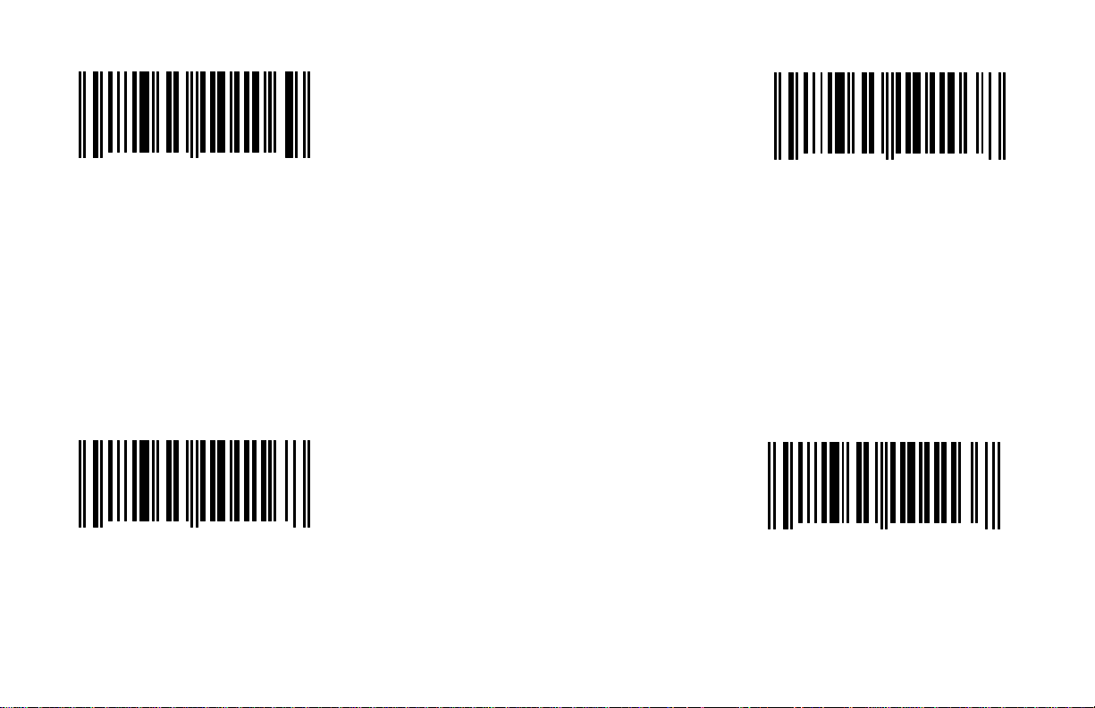
*Enable UPC/EAN *Enable Code 128
1 2 3 4 5 1 0 1 0 6
0
When this option is enabled, the scanner When this option is enabled, the scanner
will scan UPC/EAN bar codes. will scan Code 128 bar codes.
9
1 2 3 4 5 1 0 1 0 3
0
8
Disable UPC/EAN
1 2 3 4 5 1 0 1 1 6
0
When this option is disabled, the scanner
will not scan UPC/EAN bar codes.
8
A - 1
Disable Code 128
1 2 3 4 5 1 0 1 1 3
0
When this option is disabled, the scanner
will not scan Code 128 bar codes.
7
Page 10
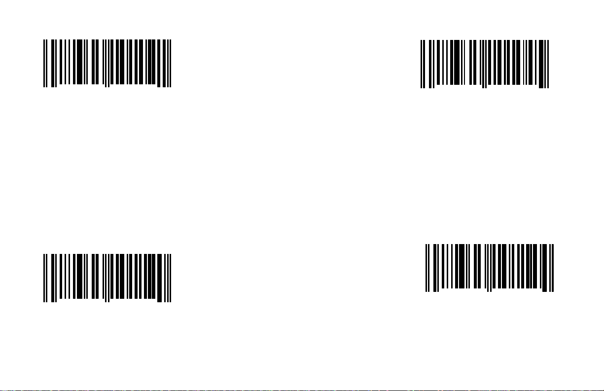
*Enable Code 93 *Enable Codabar
1 2 3 4 5 1 0 1 0 2
0
When this option is enabled, the scanner When this option is enabled, the scanner
will scan Code 93 bar codes. will scan Codabar bar codes.
1
1 2 3 4 5 1 0 1 0 4
0
5
Disable Code 93
1 2 3 4 5 1 0 1 1 2
0
When this option is disabled, the scanner
will not scan Code 93 bar codes.
0
A - 2
Disable Codabar
1 2 3 4 5 1 0 1 1 4
0
When this option is disabled, the scanner
will not scan Codabar bar codes.
4
Page 11
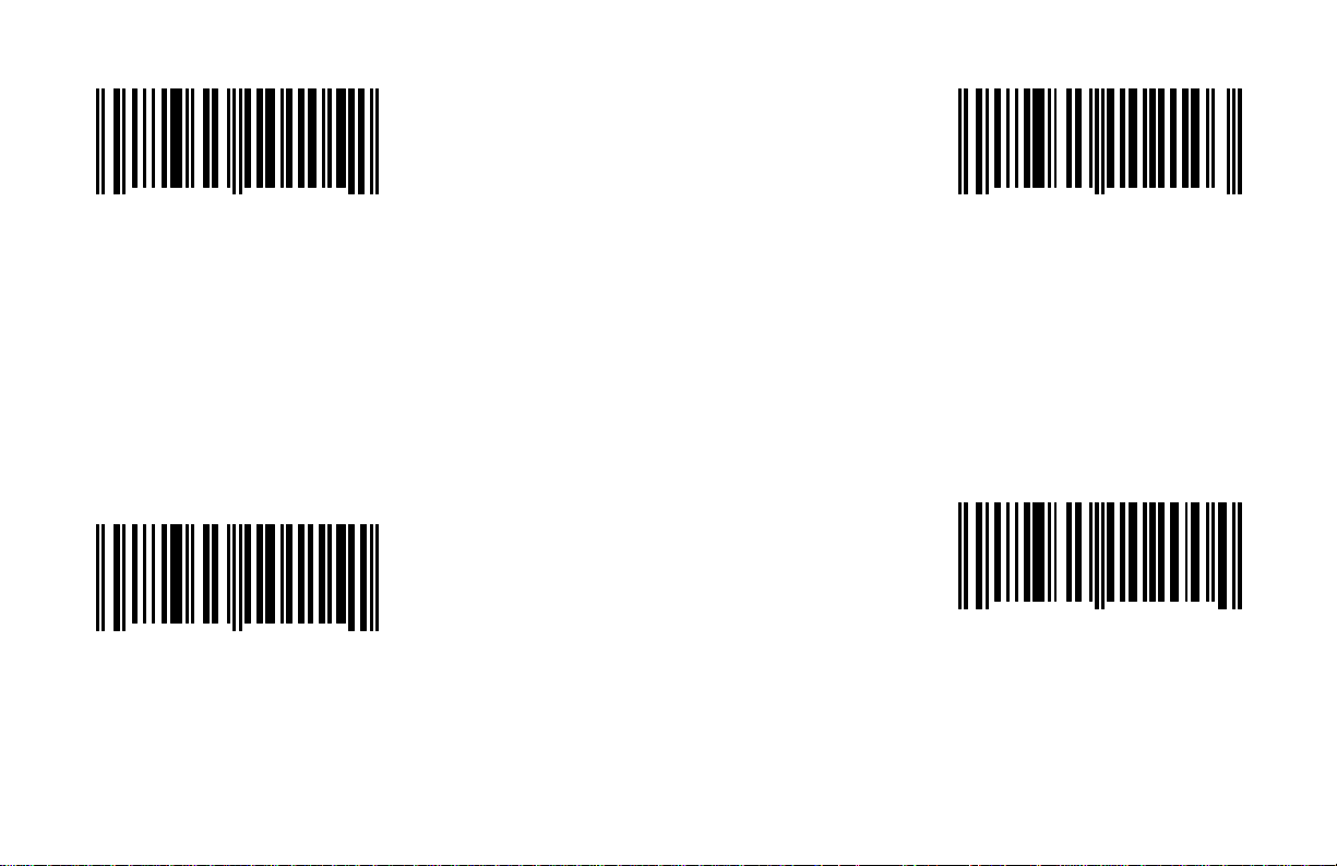
*Enable Interleaved 2 of 5 (ITF) Enable MOD 10 Check on ITF
When this option is enabled, the scanner
will scan Interleaved 2 of 5 (ITF) bar codes
When this option is disabled, the scanner
1 2 3 4 5 1 0 1 0 5
0
When this option is enabled, the scanner
will scan Interleaved 2 of 5 (ITF) bar codes.
Disable Interleaved 2 of 5 (ITF)
1 2 3 4 5 1 0 1 1 5
0
When this option is disabled, the scanner
will not scan Interleaved 2 of 5 (ITF)
bar codes.
2
1
A - 3
1 2 3 4 5 1 0 2 1 0
0
that have a Modulo 10 check digit.
*Disable MOD 10 Check on ITF
1 2 3 4 5 1 0 2 0 0
0
will not scan ITF bar codes that have a
Modulo 10 check digit.
3
4
Page 12
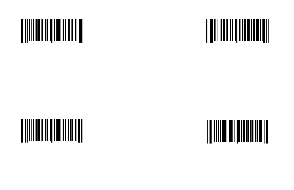
Enable Code 11 *Enable Code 39
1 2 3 4 5 1 0 2 0 3
0
When this option is enabled, the scanner When this option is enabled, the scanner
will scan Code 11 bar codes. will scan Code 39 bar codes.
*Disable Code 11
1 2 3 4 5 1 0 2 1 3
0
When this option is disabled, the scanner
will not scan Code 11 bar codes.
5
4
A - 4
1 2 3 4 5 1 0 1 0 1
0
Disable Code 39
1 2 3 4 5 1 0 1 1 1
0
When this option is disabled, the scanner
will not scan Code 39 bar codes.
3
4
Page 13

Enable Full ASCII Code 39 Enable MOD 43 Check on Code 39
will not scan Code 39 bar codes that have
1 2 3 4 5 1 0 2 1 7
0
When this option is enabled, the scanner When this option is enabled, the scanner
will scan Full ASCII Code 39 bar codes. will scan Code 39 bar codes that have a
2
1 2 3 4 5 1 0 2 1 1
0
Modulo 43 check digit.
0
*Disable Full ASCII Code 39
1 2 3 4 5 1 0 2 0 7
0
When this option is disabled, the scanner
will not scan Full ASCII Code 39 bar codes.
*Disable MOD 43 Check on Code 39
1 2 3 4 5 1 0 2 0 1
3
A - 5
0
When this option is disabled, the scanner
a Modulo 43 check digit.
1
Page 14
Enable MSI Plessey Enable MSI Plessey 10/10 Check Digits
*Enable MSI Plessey MOD 10 Check Digits
1 2 3 4 5 1 0 2 0 2
0
When this option is enabled, the scanner When this option is enabled, the scanner
will scan MSI Plessey bar codes. will scan MSI Plessey bar codes that have
*Disable MSI Plessey
1 2 3 4 5 1 0 2 1 2
0
When this option is disabled, the scanner When this option is enabled, the scanner
will not scan MSI Plessey bar codes. will scan MSI Plessey bar codes that have
8
7
A - 6
1 2 3 4 5 2 0 3 3 4
0
a double Modulo 10 check digit.
1 2 3 4 5 2 0 3 2 4
0
a single Modulo 10 check digit.
3
4
Page 15

Disable Both MSI Plessey Check Digits Enable UK Plessey
1 2 3 4 5 2 0 3 0 4
0
When this option is chosen, the scanner When this option is enabled, the scanner
will not scan MSI Plessey bar codes that will scan UK Plessey bar codes.
have a single or double Modulo 10 check
digit.
6
1 2 3 4 5 1 2 8 1 4
0
*Disable UK Plessey
1 2 3 4 5 1 2 8 0 4
0
When this option is disabled, the scanner
will not scan UK Plessey bar codes.
1
2
A - 7
Page 16
Enable Airline 2 of 5 Enable Telepen
1 2 3 4 5 1 2 9 1 1
0
When this option is enabled, the scanner will When this option is enabled, the scanner
scan Airline 2 of 5 bar codes. will scan Telepen bar codes.
*Disable Airline 2 of 5
1 2 3 4 5 1 2 9 0 1
0
When this option is disabled, the scanner
will not scan Airline 2 of 5 bar codes.
7
8
A - 8
1 2 3 4 5 1 2 9 1 6
0
*Disable Telepen
1 2 3 4 5 1 2 9 0 6
0
When this option is disabled, the scanner
will not scan Telepen bar codes.
2
3
Page 17
Enable MECCA Enable Paraf Support
will not convert Code 39 bar codes to paraf
1 2 3 4 5 1 0 2 0 5
1 2 3 4 5 1 0 1 0 0
0
When this option is enabled Metrologic When this option is enabled, the scanner
Enhanced Code Correcting Algorithm will convert Code 39 bar codes to paraf
(MECCA) will be activated. This feature format.
allows for increased accuracy in reading
poor quality bar codes, but may slightly.
reduce the aggressiveness of the scanner.
7
0
9
*Disable MECCA
1 2 3 4 5 1 0 1 1 0
0
When this option is chosen, MECCA
will not be active.
*Disable Paraf Support
1 2 3 4 5 1 0 2 1 5
6
A - 9
0
When this option is disabled, the scanner
format.
8
Page 18
Enable Matrix 2 of 5 *Enable EAN-8
1 2 3 4 5 1 2 9 1 2
0
When this option is enabled, the scanner When this option is enabled, the scanner
will scan Matrix 2 of 5 bar codes will scan EAN-8 bar codes.
4
1 2 3 4 5 1 0 2 1 4
0
1
*Disable Matrix 2 of 5
1 2 3 4 5 1 2 9 0 2
0
When this option is disabled, the scanner
will not scan Matrix 2 of 5 bar codes.
5
A - 10
Disable EAN-8
1 2 3 4 5 1 0 2 0 4
0
When this option is chosen, the scanner
will not scan EAN-8 bar codes.
2
Page 19
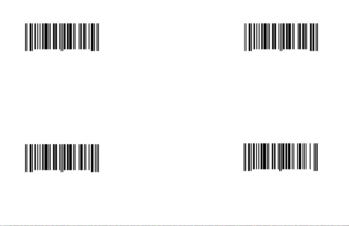
*Enable EAN-13 *Enable UPC-E
1 2 3 4 5 1 0 3 1 7
0
When this option is enabled, the scanner When this option is enabled, the scanner
will scan EAN-13 bar codes. will scan UPC-E bar codes.
Disable EAN-13
1 2 3 4 5 1 0 3 0 7
0
When this option is chosen, the scanner
will not scan EAN-13 bar codes.
9
0
A - 11
1 2 3 4 5 1 0 3 1 6
0
Disable UPC-E
1 2 3 4 5 1 0 3 0 6
0
When this option is chosen, the scanner
will not scan UPC-E bar codes.
2
3
Page 20
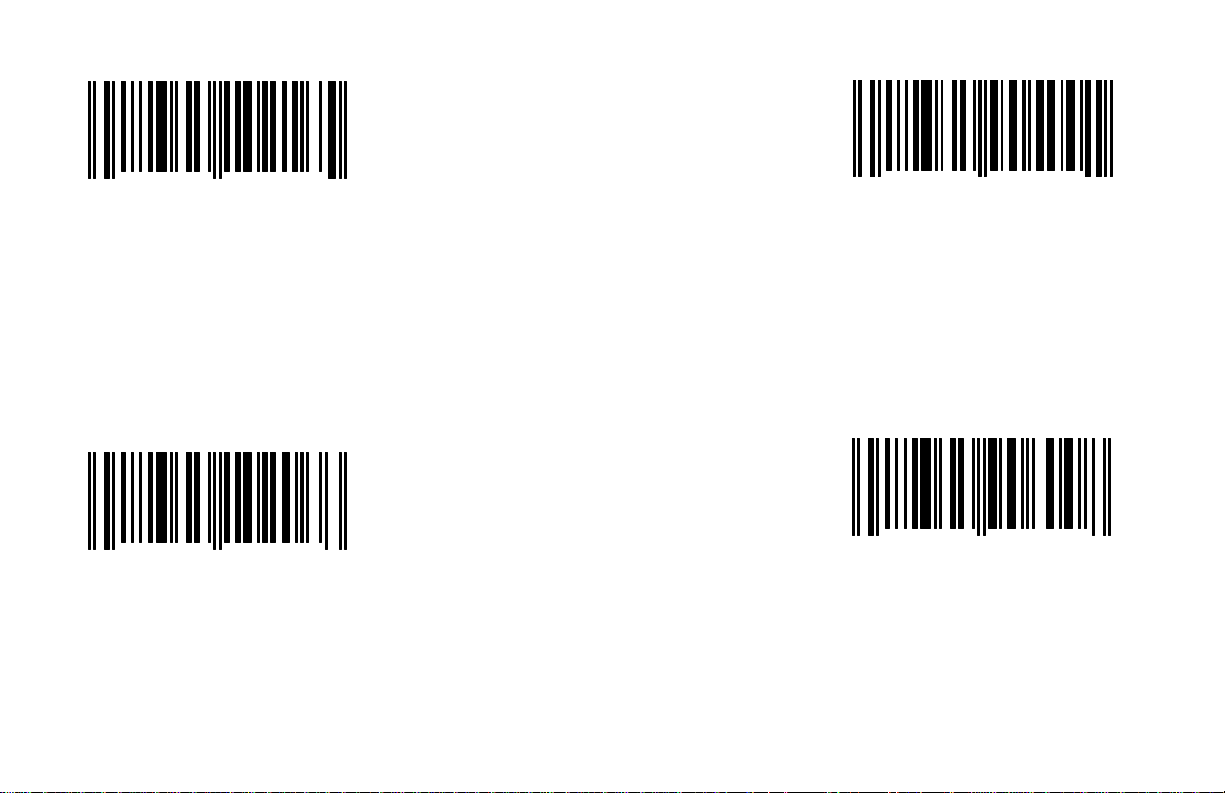
*Enable UPC-A ITF Symbol Length 1 (Byte 1)
To specify the number of ITF (Interleaved 2 of 5)
digits in the bar codes that will be scanned, scan
the above bar code and the appropriate Code
To specify a second number, scan the above
bar code and the appropriate Code Byte bar
code in Section I. Only scan the above bar code
1 2 3 4 5 1 0 2 1 6
0
When this options enabled, the scanner
will scan UPC-A bar codes.
Disable UPC-A
1 2 3 4 5 1 0 2 0 6
0
When this option is chosen, the scanner
will not scan UPC-A bar codes.
5
6
A - 12
1 2 3 4 5 9 0 5 0 0
0
Byte bar code in Section I.
ITF Symbol Length 2 (Byte 2)
1 2 3 4 5 9 0 6 0 0
0
when a second ITF number needs to be
specified.
1
8
Page 21

Minimum Symbol Length (Byte)
1 2 3 4 5 9 0 7 0 0
0
To specify the minimum number of characters
in the bar codes that will be scanned, scan the
above bar code and the appropriate Code Byte
bar code in Section I.
Symbol Length Lock (Byte)
1 2 3 4 5 9 0 8 0 0
0
When the scanner will always scan bar codes
that are the same length, the length of the bar
code can be locked into place by scanning the
above bar code and the appropriate Code Byte
bar code in Section I.
5
2
A - 13
Page 22

Section B
Communication Protocol
This section provides bar codes that can be enabled or disabled for the proper communication interface for a specific host device.
Enable RS-232 (B - 1) RS-232 Protocols (B - 3)
Enable IBM 4680 Communication (B - 1) Parallel Protocols (B - 3)
Enable Parallel Communication (B - 1) Light Pen Protocols (B - 3)
Enable Light Pen Emulation (B - 1) OCIA Protocols (B - 3)
Enable No Communication Mode (B - 2) Poll Light Pen Source (B - 4)
OCIA Output (B - 2) *Do Not Poll Light Pen Source (B - 4)
Multi-drop Network (B - 2) E/D Light Pen Extra Transition (B - 5)
Enable Keyboard Wedge Emulation (B - 4) Multi-drop Address (B - 5)
B - i
Page 23
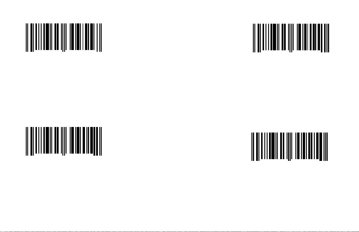
*Enable RS-232 Enable Parallel Communication
This option should be selected if the scanner
This option should be selected if the scanner
will be used in place of a light pen. It will provide
light pen emulation of each bar code that is
registers. This is not Centronics parallel and
should not be connected to such an interface.
For the most part, parallel registers allow input
1 2 3 4 5 3 0 9 5 5
0
When this option is enabled, the scanner
will work with RS-232 +-12V serial output. will provide parallel output to various cash
Enable IBM 4680 Communication
1 2 3 4 5 3 0 9 0 5
0
This option should be selected if communications with an IBM 46XX register is needed.
This will enable RS-485 communications. Not
all scanners support this interface as the correct
interface board is required. scanned.
7
2
1 2 3 4 5 3 0 9 1 5
0
of UPC/EAN bar codes only.
Enable Light Pen Emulation
1 2 3 4 5 3 0 9 2 5
0
1
0
B - 1
Page 24

Enable No Communication Mode Multi-drop Network
This option should be selected if the scanner
will provide RS-422 type output for National
This option should be selected if the scanner
will provide keyboard emulation by converting
the scanned bar code data to the PC keyboard
Semi-conductor/ICL cash registers. This is a
specific format which is only supported when
1 2 3 4 5 3 0 9 3 5
0
This option should be selected if the scanner
will not interface with a host device.
OCIA Output
1 2 3 4 5 3 0 9 4 5
0
This option should be selected if the communications requirement is OCIA (Optically Coupled
Interface Adaptor). This is a clocked (by the
host) serial interface.
9
8
B - 2
1 2 3 4 5 3 0 9 6 5
0
the proper interface board is being used.
Enable Keyboard Wedge Emulation
1 2 3 4 5 3 0 9 7 5
0
scan code equivalent.
6
5
Page 25

1 2 3 4 5 2 0 9 0 3
Spaces High/ as Scanned
Bars High/ as Scanned
0
When using one of the following, this feature
will work as indicated:
RS-232 - Odd Parity
Parallel - IBM
Light Pen - Spaces High as Code 39
OCIA - DTS/SIEMENS
1 2 3 4 5 2 0 9 1 3
0
When using one of the following communications, this
feature will work as indicated:
RS-232 = *Space Parity
Parallel - *SWEDA
Light Pen = *Bars High as Code 39
OCIA = *DTS/NIXDORF
1
0
B - 3
1 2 3 4 5 2 0 9 2 3
0
When using one of the following,
this feature will work as indicated:
RS-232 = Even Parity
Parallel = Fujitsu
Light Pen =
OCIA = NCR F
1 2 3 4 5 2 0 9 3 3
0
When using one of the following
communications, this feature will work as
indicated:
RS-232 = Mark Parity
Parallel = OMRON
Light Pen =
OCIA = NCR S
9
8
Page 26
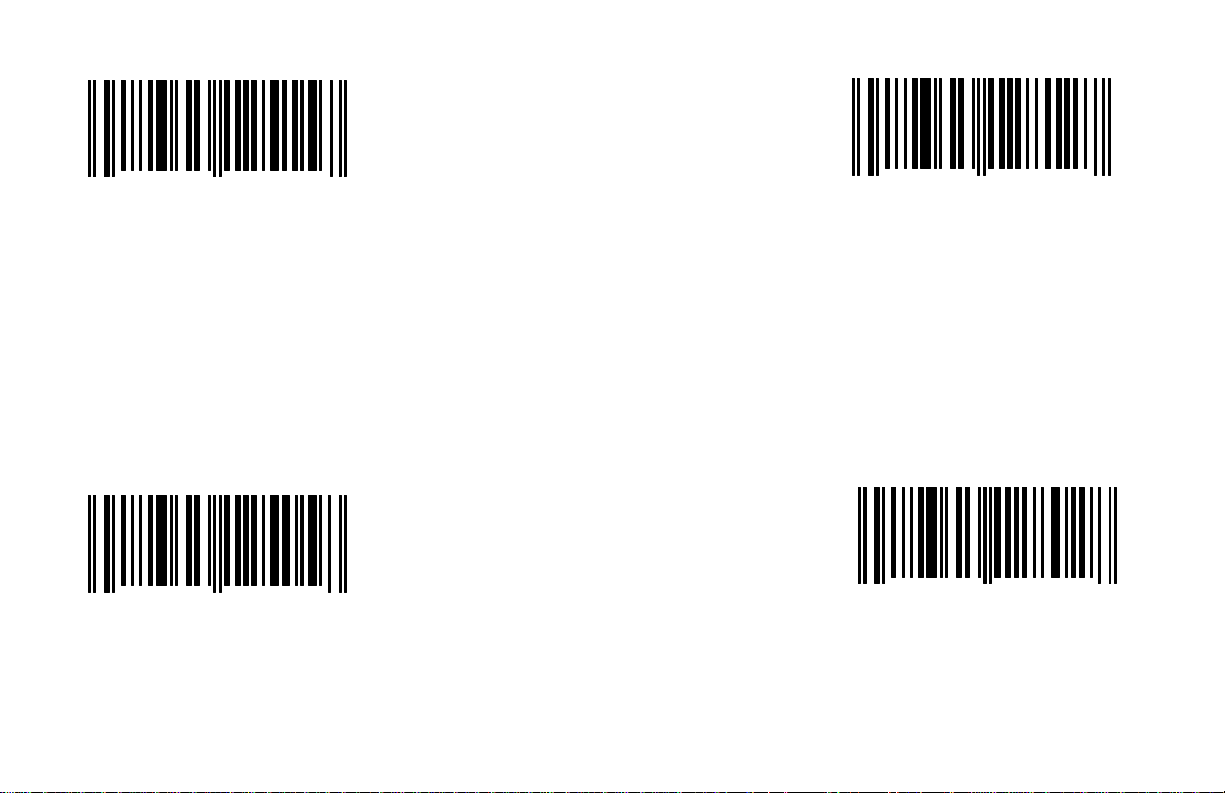
Poll Light Pen Source
Enable Light Pen Extra Transition Before Bar Code
BarCode
1 2 3 4 5 1 2 5 1 5
0
When this option is chosen, the scanner
will wait for an active source voltage before
transmitting the data.
*Do Not Poll Light Pen Source
1 2 3 4 5 1 2 5 0 5
0
When this option is chosen, the scanner
will not wait for an active source voltage
before transmitting the data.
7
8
B - 4
1 2 3 4 5 1 2 8 1 2
0
When this option is enabled, the scanner
will toggle the light pen data line prior to
transmitting the bar code. This may be
needed for certain decode devices.
*Disable Light Pen Extra Transition Before
1 2 3 4 5 1 2 8 0 2
0
When this option is disabled, the scanner
will not toggle the light pen data line prior
to transmitting the bar code.
7
8
Page 27

Multi-drop Address
1 2 3 4 5 9 3 1 0 0
0
When using Multi-drop communication, scan
the above bar code and the appropriate Code
Byte in Section I to specify the address.
Enable Keyboard Wedge Emulation
1 2 3 4 5 3 0 9 7 5
0
This option should be selected if the scanner
will provide keyboard emulation by converting
the scanned bar code data to the PC keyboard
scan code equivalent.
0
5
B - 5
Page 28

Section C
Scanner Operation
This section provides bar codes that can change the general operating characteristics of the scanner. These include beeper operation, timeout options, depth of field, and test modes.
E/D = Enable/Disable
Normal Tone (C - 1) E/D No Same Symbol Time-out (C - 6)
Alternate Tone 1 (C - 1) E/D Infinite Same Symbol Time-out (C - 7)
Alternate Tone 2 (C - 1) E/D Same Symbol Rescan Time-out: 100 msec (C - 7)
No Beep (C - 1) Same Symbol Rescan Time-out: 200 msec (C - 8)
E/D Fast Beep (C - 2) Same Symbol Rescan Time-out: 500 msec (C - 8)
Loudest Volume Setting (C - 2) Same Symbol Rescan Time-out: 1250 msec (C - 8)
Medium Volume Setting (C - 2) Same Symbol Rescan Time-out: 2000 msec (C - 8)
Lowest Volume Setting (C - 3) Scanability On/Off (C - 9)
Quietest (No Volume) (C - 3) Scan Count Mode On/Off (C - 9)
Beep Before/After Transmit (C - 3) Extended Depth of Field (C - 10)
E/D Communication Time-outs (C - 4) Normal Depth of Field (C - 10)
Razz Tone on Time-out (C - 4) Close Depth of Field (C - 10)
No Razz Tone on Time-out (C - 4) Intercharacter Delay:
Three Beeps on Time-out (C - 5) RS-232 Protocols (C - 11, C - 12)
No Beeps on Time-out (C - 5) Parallel Protocols (C - 11, C - 12)
10 Min Touchplate/IR Time-out (C - 5) OCIA Protocols (C - 11, C - 12)
2 Min Touchplate/IR Time-out (C - 5) KB Wedge Protocols (C - 11, C - 12)
30 Min Touchplate/IR Time-out (C - 6) 1 Scan Buffer (C - 13)
No Touchplate/IR Time-out (C - 6) 2 Scan Buffers (C - 13)
C - i
Page 29
*Normal Tone Alternate Tone 2
available: Normal, Alt 1, Alt 2, and No Beep.
When No Beep is chosen, the scanner will not
available: Normal, Alt 1, Alt 2, and No Beep.
When No Beep is chosen, the scanner will not
1 2 3 4 5 2 1 0 3 6
0
The following beeper tone options are available: The following beeper tone options are
Normal, Alt 1, Alt 2, and No Beep. When
No Beep is chosen, the scanner will not
emit an audible beep. emit an audible beep.
Alternate Tone 1 No Beep
1 2 3 4 5 2 1 0 2 6
0
The following beeper tone options are available: The following beeper tone options are
Normal, Alt 1, Alt 2, and No Beep. When No
Beep is chosen, the scanner will not emit an
audible beep. emit an audible beep.
5
6
C - 1
1 2 3 4 5 2 1 0 1 6
0
1 2 3 4 5 2 1 0 0 6
0
8
7
Page 30
Enable Fast Beep *Loudest Volume Setting
chosen, the scanner will not emit an audible
chosen, the scanner will not emit an audible
1 2 3 4 5 1 2 8 1 0
0
When this option is selected, the scanner
will use the selected tone but shorten the
duration of the beep.
*Disable Fast Beep
1 2 3 4 5 1 2 8 0 0
0
When this option is selected, the scanner
will not shorten the beep duration.
3
4
C - 2
1 2 3 4 5 2 1 0 3 4
0
The following beeper volume options are
available: Quietest (No Volume), Lowest,
Medium, and Loudest. When Quietest is
beep.
Medium Volume Setting
1 2 3 4 5 2 1 0 2 4
0
The following beeper volume options are
available: Quietest (No Volume), Lowest,
Medium, and Loudest. When Quietest is
beep.
1
2
Page 31

Lowest Volume Setting *Beep Before Transmit
1 2 3 4 5 1 1 0 1 3
1 2 3 4 5 2 1 0 1 4
0
The following beeper volume options
are available: Quietest (No Volume),
Lowest, Medium, and Loudest. When
Quietest is chosen, the scanner will
not emit an audible beep.
3
0
When this option is chosen, the scanner
will beep before each label is transmitted.
9
Quietest (No Volume)
1 2 3 4 5 2 1 0 0 4
0
The following beeper volume options are
available: Quietest (No Volume), Lowest,
Medium, and Loudest. When Quietest is
chosen, the scanner will not emit an audible
beep.
4
C - 3
Beep After Transmit
1 2 3 4 5 1 1 0 0 3
0
When this option is chosen, the scanner
will beep after each label is transmitted.
0
Page 32
Enable Communication Time-outs Razzberry Tone on Time-out
will not produce an audible razzberry tone
1 2 3 4 5 1 1 0 1 2
0
When this option is enabled, the scanner will When this option is chosen, the scanner
time-out if it does not transmit its data to the will produce an audible razzberry tone
host after two seconds during communication. when communications have timed out.
This is only valid in modes where some type of
handshaking is involved.
*Disable Communication Time-outs
1 2 3 4 5 1 1 0 0 2
0
When this option is disabled, the scanner will
not time-out if it does not transmit its data to When this option is chosen, the scanner
the host after two seconds during communication. This is only valid in modes where some when communications have timed out.
type of handshaking is involved.
2
3
1 2 3 4 5 1 1 0 1 1
0
No Razzberry Tone on Time-out
1 2 3 4 5 1 1 0 0 1
0
5
6
C - 4
Page 33
Three Beeps on Time-out *10 Minutes Touchplate/IR Time-outs
This time represents the duration of time of
inactivity from the last scan until the scanner
enters a “standby” mode. The scanner will not
return to scanning until either the scanner’s
touchplate is pressed or an object is waved
This time represents the duration of time of
inactivity from the last scan until the scanner
enters a “standby” mode. The scanner will not
return to scanning until either the scanner’s
touchplate is pressed or an object is waved in
1 2 3 4 5 1 1 0 1 0
0
When this option is chosen, the scanner
will beep three times when communications
have timed out.
8
1 2 3 4 5 2 0 9 3 0
0
in front of the IR sensor.
7
No Beeps on Time-out
1 2 3 4 5 1 1 0 0 0
0
When this option is chosen, the scanner
will not beep when communications
have timed out.
9
C - 5
Two Minutes Touchplate/IR Time-outs
1 2 3 4 5 2 0 9 2 0
0
front of the IR sensor.
8
Page 34
Thirty Minutes Touchplate/IR Time-outs Enable No Same Symbol Time-out
1 2 3 4 5 2 0 9 1 0
0
This time represents the duration of time of When this option is enabled, the same
inactivity from the last scan until the scanner bar code is scanned again without any
enters a “standby” mode. The scanner will not time delay. When enabled, this option
return to scanning until either the scanner’s overrides any selected same symbol
touchplate is pressed or an object is waved in rescan time-out option.
front of the IR sensor.
No Touchplate/IR Time-outs *Disable No Same Symbol Time-out
9
1 2 3 4 5 1 2 8 1 5
0
8
1 2 3 4 5 2 0 9 0 0
0
When this option is chosen, the scanner will When this option is disabled, there is
not enter a “standby” mode. When using a a same symbol rescan time-out.
Tech scanner, select this option since these
units do not have an IR sensor or a touchplate.
0
C - 6
1 2 3 4 5 1 2 8 0 5
0
9
Page 35
Enable Infinite Same Symbol Time-out
Enable Same Symbol Rescan Time-out: 100
*Disable Same Symbol Rescan Time-out:
1 2 3 4 5 1 2 8 1 6
0
When this option is enabled, the scanner never
scans the same bar code repetitively during a
scanning session. When enabled, this option
overrides all of the same symbol rescan time-outs.
5
msec
1 2 3 4 5 1 2 8 1 1
0
The available same symbol time-outs
are 100, 200, 500, 1250 and 2000
milliseconds. These numbers represent
the amount of time that a bar code must
be out of the scan field before that bar
code can be scanned again.
0
*Disable Infinite Same Symbol Time-out
1 2 3 4 5 1 2 8 0 6
0
When this option is disabled, the same bar
code can be scanned again after a rescan time-out.
6
C - 7
100 msec
1 2 3 4 5 1 2 8 0 1
0
When this option is disabled, any other
selected same symbol rescan time-out
will be recognized. Note: If 100 mesc is
enabled, the time-out will override all
other rescan time-outs until the above
bar code is scanned.
1
Page 36
Same Symbol Rescan Time-out 200 msecs
Same Symbol Rescan Time-out: 1250 msecs
are 200, 500, 1250 and 2000 milliseconds.
Same Symbol Rescan Time-out 2000 msecs
are 200, 500, 1250 and 2000 milliseconds.
1 2 3 4 5 2 1 1 3 0
0
The available same symbol time-outs are 200, The available same symbol time-outs
500, 1250 and 2000 milliseconds. These
numbers represent the amount of time that a These numbers represent the amount of
bar code must be out of the scan field before time that a bar code must be out of the
that bar code can be scanned again. scan field before that bar code can be
*Same Symbol Rescan Time-out: 500 msecs
1 2 3 4 5 2 1 1 2 0
0
The available same symbol time-outs are 200, The available same symbol time-outs
500, 1250 and 2000 milliseconds. These
numbers represent the amount of time that a These numbers represent the amount of
bar code must be out of the scan field before time that a bar code must be out of the
that bar code can be scanned again. scan field before that bar code can be
0
1
C - 8
1 2 3 4 5 2 1 1 1 0
0
scanned again.
1 2 3 4 5 2 1 1 0 0
0
scanned again.
2
3
Page 37

Scanability On Scan Count Mode On
will enter scan count test mode. The firmware
number of the scanner will also be transmitted
to the host device. Do not enable this feature
unless instructed to do so by a Metrologic
Do not enable this feature unless instructed
1 2 3 4 5 1 1 1 1 7
0
When this option is enabled, the scanner will When this option is enabled, the scanner
enter scanability test mode. Do not enable this
feature unless instructed to do so by a
Metrologic representative.
*Scanability Off
1 2 3 4 5 1 1 1 0 7
0
Do not enable this feature unless instructed to
do so by a Metrologic representative.
4
5
C - 9
1 2 3 4 5 1 1 1 1 6
0
representative.
*Scan Count Mode Off
1 2 3 4 5 1 1 1 0 6
0
to do so by a Metrologic representative.
7
8
Page 38

Extended Depth of Field Close Depth of Field
Do not change this setting unless instructed
1 2 3 4 5 2 1 6 0 0
0
Do not change this setting unless instructed to
do so by a Metrologic representative.
*Normal Depth of Field
1 2 3 4 5 2 1 6 1 0
0
Do not change this setting unless instructed to
do so by a Metrologic representative.
8
7
1 2 3 4 5 2 1 6 2 0
0
to do so by a Metrologic representative.
6
C - 10
Page 39
Intercharacter Delay Intercharacter Delay
of time in between transmission of characters.
KB Wedge - 10 mesc
of time in between transmission of characters.
KB Wedge - 100 mesc
1 2 3 4 5 3 1 1 3 2
0
If the host device does not require an
intercharacter delay, choose this option.
RS-232 - None OCIA - None
Parallel - None KB Wedge - None
Intercharacter Delay
1 2 3 4 5 3 1 1 2 2
0
The time specified represents the interim of
time in between transmission of characters.
RS-232 - *1 msec OCIA - *1 msec
Parallel - *1 msec KB Wedge - *1 msec
1
2
C - 11
1 2 3 4 5 3 1 1 1 2
0
The time specified represents the interim
RS-232 - 5 mesc OCIA - 5 mesc
Parallel - 2 mesc
Intercharacter Delay
1 2 3 4 5 3 1 1 0 2
0
The time specified represents the interim
RS-232 - 20 mesc OCIA - 20 mesc
Parallel - 5 mesc
3
4
Page 40
Intercharacter Delay Intercharacter Delay
The time specified represents the interim of
time in between transmission of characters.
KB Wedge - 50 mesc
The time specified represents the interim of
time in between transmission of characters.
KB Wedge - 75 mesc
1 2 3 4 5 3 1 7 0 0
0
The time specified represents the interim of
time in between transmission of characters.
RS-232 - Reserved OCIA - Reserved RS-232 - Reserved OCIA - Reserved
Parallel - Reserved KB Wedge - 5 mesc Parallel - Reserved
Intercharacter Delay Intercharacter Delay
1 2 3 4 5 3 1 1 6 2
0
The time specified represents the interim of
time in between transmission of characters.
RS-232 - Reserved OCIA - Reserved RS-232 - Reserved OCIA - Reserved
Parallel - Reserved KB Wedge - 25 mesc Parallel - Reserved
2
8
1 2 3 4 5 3 1 1 5 2
0
1 2 3 4 5 3 1 1 4 2
0
9
0
C - 12
Page 41

*1 Scan Buffer
1 2 3 4 5 1 0 9 0 2
0
When this option is enabled, the scanner will
scan continuously if two different labels are in
the scan field.
2 Scan Buffers
1 2 3 4 5 1 0 9 1 2
0
When this option is enabled, the scanner will
scan two different labels in the scan field once.
It will not scan the bar code again until the
same symbol time-out has elapsed.
7
6
C - 13
Page 42

Section D
General Format Options
This section provides bar codes that can be chosen to select the output format for UPC/EAN bar codes and transmission formats for NonUPC scanned data. Many of the formatting options are dependent upon which interface is being used.
DN/T = Do Not Transmit/Transmit
DN/T UPC-A Check Digit (D - 1) DN/T Codabar Start/Stop Characters (D - 5)
DN/T UPC-E Check Digit (D - 1) DN/Enable CLSI Editing (D - 6)
DN/Expand UPC - E (D - 2) DN/T Mod 43 Check Digit on Code 39 (D - 6)
DN/Convert UPC-A to EAN-13 (D - 2) DN/T Code 39 Start/Stop Characters (D - 7)
DN/T Lead Zero on UPC-E (D - 3) DN/T Mod 10/ITF (D - 7)
DN/Convert EAN-8 to EAN-13 (D - 3) DN/T Code 11 Check Digit (D - 8)
DN/T EAN-13 Check Digit (D - 4) DN/T MSI Plessey Check Digits (D - 8)
DN/T EAN-8 Check Digit (D - 4) DN/T UK Plessey Check Digits (D - 9)
DN/T UPC-A Number System (D - 5)
D - i
Page 43
*Transmit UPC-A Check Digit Transmit UPC-E Check Digit
1 2 3 4 5 1 1 4 1 6
1 2 3 4 5 1 1 4 1 7
0
When this option is chosen, the scanner When this option is chosen, the scanner
will transmit the UPC-A check digit. will transmit the UPC-E check digit.
5
0
8
Do not Transmit UPC-A Check Digit
1 2 3 4 5 1 1 4 0 7
0
When this option is chosen, the scanner
will not transmit the UPC-A check digit.
6
D - 1
*Do not Transmit UPC-E Check Digit
1 2 3 4 5 1 1 4 0 6
0
When this option is chosen, the scanner
will not transmit the UPC-E check digit.
9
Page 44
Expand UPC-E Convert UPC-A to EAN-13
will convert UPC-A to EAN-13 by transmitting
1 2 3 4 5 1 1 4 1 5
0
When this option is chosen, the scanner
will expand UPC-E to the 12 digit
equivalent UPC-A.
1
1 2 3 4 5 1 1 4 1 4
0
When this option is chosen, the scanner
a leading zero before the bar code.
4
*Do not Expand UPC-E
1 2 3 4 5 1 1 4 0 5
0
When this option is chosen, the scanner
will not expand UPC-E to the 12 digit
equivalent UPC-A.
2
D - 2
*Do not Convert UPC-A to EAN-13
1 2 3 4 5 1 1 4 0 4
0
When this option is chosen, the scanner
will not convert UPC-A to EAN-13.
5
Page 45
Transmit Lead Zero on UPC-E Convert EAN-8 to EAN-13
When this option is chosen, the scanner will
convert EAN-8 to EAN-13 by transmitting five
When this option is chosen, the scanner will not
1 2 3 4 5 1 1 4 1 2
1 2 3 4 5 1 1 4 1 3
0
When this option is chosen, the scanner
will output a zero before each UPC-E bar code.
*Do not Transmit Lead Zero on UPC-E
1 2 3 4 5 1 1 4 0 3
0
When this option is chosen, the scanner
will not output a zero before each UPC-E bar code.
7
8
0
zeroes before the bar code.
*Do not Convert EAN-8 to EAN-13
1 2 3 4 5 1 1 4 0 2
0
convert EAN-8 to EAN-13.
0
1
D - 3
Page 46

*Transmit EAN-13 Check Digit *Transmit EAN-8 Check Digit
1 2 3 4 5 1 1 2 0 0
1 2 3 4 5 1 1 2 0 2
0
When this option is chosen, the scanner When this option is chosen, the scanner
will transmit the EAN-13 check digit. will transmit the EAN-8 check digit.
Do not Transmit EAN-13 Check Digit Do not Transmit EAN-8 Check Digit
7
0
3
1 2 3 4 5 1 1 2 1 2
0
When this option is chosen, the scanner When this option is chosen, the scanner
will not transmit the EAN-13 check digit. will not transmit the EAN-8 check digit.
6
D - 4
1 2 3 4 5 1 1 2 1 0
0
2
Page 47
*Transmit UPC-A Number System
Transmit Codabar Start/Stop Characters
When this option is chosen, the scanner will
transmit Codabar's start and stop characters
*Do not Transmit Codabar Start/Stop Characters
When this option is chosen, the scanner will not
transmit Codabar's start and stop characters
1 2 3 4 5 1 1 4 1 1
0
When this option is chosen, the scanner will
transmit the UPC-A number system character.
Do not Transmit UPC-A Number System
1 2 3 4 5 1 1 4 0 1
0
Metrologic strongly discourages the disabling
of this feature because duplicate numbers
may result in the database when the scanner
is programmed not to transmit the UPC-A
number system character.
3
4
D - 5
1 2 3 4 5 1 1 5 1 7
0
before and after each bar code.
1 2 3 4 5 1 1 5 0 7
0
before and after each bar code.
2
3
Page 48

Enable CLSI Editing
Transmit Mod 43 Check Digit on Code 39
When this option is chosen, the scanner will
transmit Code 39’s Mod 43 check character.
This feature works in conjunction with the Mod
43 Check on Code 39 option in Section A. Both
must be enabled in order for this feature to work.
*Do not Transmit Mod 43 Check Digit on
When this option is chosen, the scanner will
not transmit Code 39’s Mod 43 check character.
1 2 3 4 5 1 1 5 1 6
0
When this option is enabled, the scanner
will perform CLSI library type editing before
the information is transmitted to the host.
This editing only works with 14 digit Codabar
type labels.
*Do not Enable CLSI Editing
1 2 3 4 5 1 1 5 0 6
0
When this option is chosen, the scanner
will not perform CLSI library type editing
before the information is transmitted to the
host.
5
6
D - 6
1 2 3 4 5 1 1 5 1 5
0
Code 39
1 2 3 4 5 1 1 5 0 5
0
8
9
Page 49
Transmit Code 39 Stop/Start Characters Transmit Mod 10/ITF
When this option is chosen, the scanner will
transmit the Interleaved 2 of 5 (ITF) mod 10
not transmit the Interleaved 2 of 5 (ITF) mod 10
conjunction with the Mod 10 Check on ITF in
Section A. Both must be enabled in order for this
When this option is chosen, the scanner will
1 2 3 4 5 1 1 5 1 0
0
When this option is chosen, the scanner will
transmit Code 39’s start and stop characters
before and after each bar code. check character. This feature works in
*Do not Transmit Code 39 Start/Stop Characters
1 2 3 4 5 1 1 5 0 0
0
When this option is chosen, the scanner will
not transmit Code 39’s start and stop characters check character.
before and after each bar code.
3
4
D - 7
1 2 3 4 5 1 1 5 1 4
0
feature to work.
*Do not Transmit Mod 10/ITF
1 2 3 4 5 1 1 5 0 4
0
1
2
Page 50
Transmit Code 11 Check Digit Transmit MSI Plessey Check Digits
When this option is chosen, the scanner will
transmit MSI Plessey’s check digit characters.
Plessey options in Section A. This option and
one or both of the MSI Plessey Mod options
must be enabled in order for this feature to work.
*Do not Transmit MSI Plessey Check Digits
When this option is chosen, the scanner will not
transmit MSI Plessey’s check digit characters.
1 2 3 4 5 1 1 5 1 3
0
When this option is chosen, the scanner will
transmit Code 11 check characters. This
feature works in conjunction with the Enable This feature works in conjunction with the
Code 11 option in Section A. Both must be
enabled in order for this feature to work.
*Do not Transmit Code 11 Check Digit
1 2 3 4 5 1 1 5 0 3
0
When this option is chosen, the scanner will
not transmit Code 11 check characters.
4
5
D - 8
1 2 3 4 5 1 1 5 1 1
0
1 2 3 4 5 1 1 5 0 1
0
0
1
Page 51

Transmit UK Plessey Check Digits
1 2 3 4 5 1 2 9 1 7
0
When this option is chosen, the scanner will
transmit UK Plessey’s check digit characters.
This feature works in conjunction with the UK
Plessey option in Section A.
*Do not Transmit UK Plessey Check Digits
1 2 3 4 5 1 2 9 0 7
0
When this option is chosen, the scanner will
not transmit UK Plessey’s check digit characters.
9
0
D - 9
Page 52

Section E
RS-232 Parameters
All of the options in this section are available with RS-232 communication. However, some of the data formatting options also apply for
keyboard wedge mode.
E/D = Enable/Disable
DN/T = Do Not Transmit/Transmit
Odd/Space Parity (E - 1) E/D UPC Suffix (E - 9)
Even/Mark Parity (E - 1) E/D STX Prefix (E - 9)
19200/9600 Baud Rate (E - 2) E/D ETX Suffix (E - 10)
4800/2400 Baud Rate (E - 2) E/D Carriage Return (E - 10)
1200/600 Baud Rate (E - 3) E/D Line Feed (E - 11)
300/38400 Baud Rate (E - 3) E/D Tab Prefix (E - 11)
8/7 Data Bits (E - 4) E/D Tab Suffix (E - 12)
DN/T Sanyo ID Characters (E - 4) E/D DE Disable Command (E - 12)
E/D Shell/Schulmberger Formatting (E - 5) E/D FL Laser Enable Command (E - 13)
E/D SNI Beetle Mode (E - 5) E/D DTR Handshaking Support (E - 13)
E/D French PC Term (E - 6) E/D RTS/CTS Handshaking (E - 14)
DN/T AIM ID Characters (Chrs.) (E - 6) Character/Message RTS/CTS (E - 14)
E/D Nixdorf ID (E - 7) E/D XON/XOFF Handshaking (E - 15)
Program Prefix Chrs., RS-232 (Byte 1)/(Byte 2) (E - 7) E/D ACK/NAK (E - 15)
Program Suffix Chrs., RS-232 (Byte 1)/(Byte 2) (E - 8) E/D 5 Retries ACK/NAK Time-out (E - 16)
E/D UPC Prefix (E - 8)
E - i
Page 53
Odd Parity Even Parity
The scanner's parity must match the host's
potential single-bit data transmission errors.
The scanner's parity must match the host's
1 2 3 4 5 2 0 9 0 3
0
Parity is an extra bit attached to the transmitted data byte which is used to catch parity. Select even to make the additional
potential single-bit data transmission errors. parity bit either a 0 or 1 to guarantee that
The scanner's parity must match the host's an even number of bits are ones.
parity. Select odd to make the additional
parity bit either a 0 or 1 to guarantee that
an odd number of bits are ones.
1
1 2 3 4 5 2 0 9 2 3
0
9
*Space Parity
1 2 3 4 5 2 0 9 1 3
0
Parity is an extra bit attached to the transmitted data byte which is used to catch
potential single-bit data transmission errors.
The scanner's parity must match the host's
parity. Select space to make the parity bit
always 0.
Mark Parity
0
E - 1
1 2 3 4 5 2 0 9 3 3
0
Parity is an extra bit attached to the transmitted data byte which is used to catch
parity. Select mark to make the parity bit
always 1.
8
Page 54
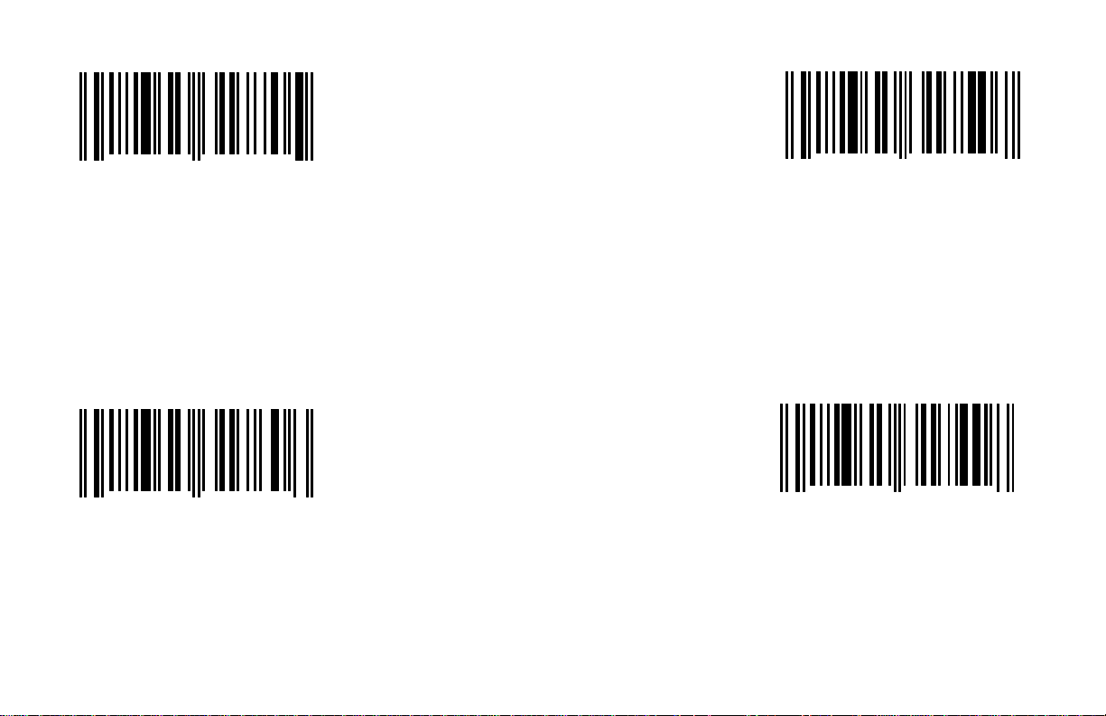
19200 Baud Rate 4800 Baud Rate
A baud rate is a unit that measures the speed
with which information is transferred. The baud
rate of the scanner must equal the baud rate of
the host device. Select the rate that matches
A baud rate is a unit that measures the speed
with which information is transferred. The baud
rate of the scanner must equal the baud rate of
the host device. Select the rate that matches
1 2 3 4 5 3 1 7 7 0
0
A baud rate is a unit that measures the
speed with which information is transferred.
The baud rate of the scanner must equal the
baud rate of the host device. Select the rate
that matches the host device’s requirements.
*9600 Baud Rate
1 2 3 4 5 3 1 7 6 0
0
A baud rate is a unit that measures the speed
with which information is transferred. The baud
rate of the scanner must equal the baud rate of
the host device. Select the rate that matches the
host device’s requirements.
5
6
E - 2
1 2 3 4 5 3 1 7 5 0
0
the host device’s requirements.
2400 Baud Rate
1 2 3 4 5 3 1 7 4 0
0
the host device’s requirements.
7
8
Page 55
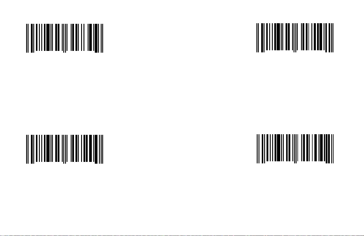
1200 Baud Rate 300 Baud Rate
A baud rate is a unit that measures the speed
with which information is transferred. The baud
rate of the scanner must equal the baud rate of
the host device. Select the rate that matches
A baud rate is a unit that measures the speed
with which information is transferred. The baud
rate of the scanner must equal the baud rate of
the host device. Select the rate that matches
1 2 3 4 5 3 1 7 3 0
0
A baud rate is a unit that measures the speed
with which information is transferred. The baud
rate of the scanner must equal the baud rate of
the host device. Select the rate that matches the
host device’s requirements. the host device’s requirements.
600 Baud Rate 38400 Baud Rate
1 2 3 4 5 3 1 7 2 0
0
A baud rate is a unit that measures the speed
with which information is transferred. The baud
rate of the scanner must equal the baud rate of
the host device. Select the rate that matches the
host device’s requirements. the host device’s requirements.
9
0
E - 3
1 2 3 4 5 3 1 7 1 0
0
1 2 3 4 5 3 1 7 0 0
0
1
2
Page 56
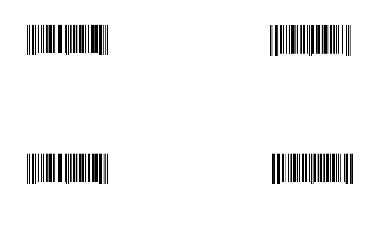
8 Data Bits Transmit Sanyo ID Characters
When this option is chosen, the scanner will
transmit code identifiers before each bar code.
These identifiers are expected by many Sanyo
*Do not Transmit Sanyo ID Characters
When this option is chosen, the scanner will
not transmit code identifiers before each bar
1 2 3 4 5 1 1 9 1 4
0
RS-232 serial communication requires ASCII
data to be transmitted in either 7 or 8 data bits.
In addition, one parity bit will be transmitted. If
the host device requires 8 data bits, select this registers.
option.
*7 Data Bits
9
1 2 3 4 5 1 1 9 1 6
0
3
1 2 3 4 5 1 1 9 0 4
0
RS-232 serial communication requires ASCII
data to be transmitted in either 7 or 8 data bits.
In addition, one parity bit will be transmitted. code.
0
E - 4
1 2 3 4 5 1 1 9 0 6
0
4
Page 57
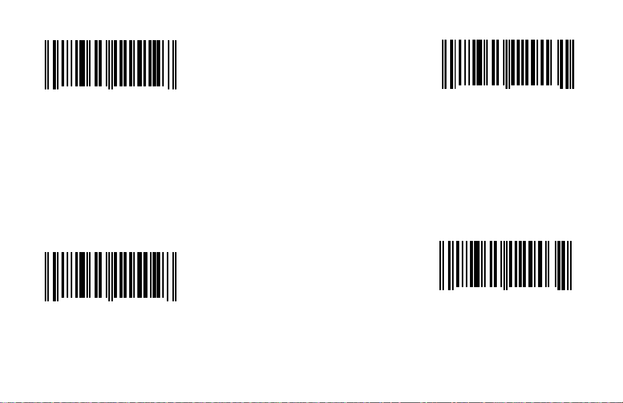
Enable Shell/Schulmberger Formatting Enable SNI Beetle Mode
will transmit the ID characters that SNI Beetle
When this option is disabled, the scanner
will not transmit the ID characters that the
1 2 3 4 5 1 1 5 1 2
0
When this option is chosen, the scanner When this option is enabled, the scanner
will output an LRC (check character) after
the bar code. In addition, ETX suffix and cash register expects.
STX prefix must be enabled while CR and
LF must be disabled.
*Disable Shell/ Schulmberger Formatting
1 2 3 4 5 1 1 5 0 2
0
When this option is chosen, the scanner
will not output an LRC (check character)
after the bar code.
7
8
E - 5
1 2 3 4 5 1 2 9 1 3
0
*Disable SNI Beetle Mode
1 2 3 4 5 1 2 9 0 3
0
SNI Beetle cash register expects.
1
2
Page 58
Enable French PC Term Transmit AIM ID Characters
Currently, the scanners do not support this
will not transmit AIM symbology identifiers.
Currently, the scanners do not support this
1 2 3 4 5 1 2 9 1 4
0
When this option is enabled, the scanner When this option is chosen, the scanner
will transmit PC type make/break scan will transmit AIM symbology identifiers.
codes instead of ASCII data characters.
*Disable French PC Term *Do not Transmit AIM ID Characters
1 2 3 4 5 1 2 9 0 4
0
When this option is disabled, the scanner
will not transmit PC type make/break scan
codes instead of ASCII data characters.
8
9
1 2 3 4 5 1 1 9 1 5
0
feature.
1 2 3 4 5 1 1 9 0 5
0
When this option is chosen, the scanner
feature.
6
7
E - 6
Page 59

Enable Nixdorf ID
Programmable Prefix Characters, RS-232
When this option is chosen, one programmable
prefix ID character can be assigned and added
to the scanned data transmission. To specify
the character, scan the above bar code and the
Programmable Prefix Characters, RS-232
transmission. To specify the second character,
scan the above bar code and the appropriate
1 2 3 4 5 1 1 9 1 7
0
When this option is enabled, the scanner will
transmit the code identifiers before each bar
code. Many Siemens/Nixdorf registers require
these code identifiers.
0
(Byte1)
1 2 3 4 5 9 2 0 0 0
0
appropriate Code Byte in Section I.
4
*Disable Nixdorf ID
1 2 3 4 5 1 1 9 0 7
0
When this option is chosen, the scanner will
not transmit the code identifiers before each
bar code.
1
E - 7
(Byte 2)
1 2 3 4 5 9 2 1 0 0
0
When this option is chosen, a second
programmable prefix ID character can be
assigned and added to the scanned data
Code Byte in Section I.
1
Page 60
Programmable Suffix Characters, RS-232 (Byte1) Enable UPC Prefix
When this option is enabled, the scanner will
transmit a prefix before any UPC/EAN bar
code. The prefixes are A (UPC-A), EO (UPC-
When this option is chosen, the scanner will
not transmit a prefix before any UPC/EAN bar
1 2 3 4 5 9 2 2 0 0
0
When this option is chosen, one programmable
suffix ID character can be assigned and added
to the scanned data transmission. To specify
the character, scan the above bar code and E), F (EAN-13) and FF (EAN-8).
the appropriate Code Byte in Section I.
Programmable Suffix Characters, RS-232 (Byte2) *Disable UPC Prefix
1 2 3 4 5 9 2 3 0 0
0
When this option is chosen, a second programmable
suffix ID character can be assigned and added to the
scanned data transmission. To specify the second code.
character, scan the above bar code and the appropriate
Code Byte in Section I.
8
5
E - 8
1 2 3 4 5 1 1 8 1 7
0
1 2 3 4 5 1 1 8 0 7
0
3
4
Page 61

Enable UPC Suffix Enable STX Prefix
When this option is enabled, the scanner will
t (ASCII 02H) before
When this option is chosen the scanner will not
t (ASCII 02H) before
1 2 3 4 5 1 1 8 1 5
1 2 3 4 5 1 1 8 1 6
0
When this option is enabled, the scanner will
transmit a suffix after any UPC/EAN bar code. transmit a Start of TeX
The suffixes are A (UPC-A), EO (UPC-E), F each bar code.
(EAN-13) and FF (EAN-8).
6
0
9
*Disable UPC Suffix
1 2 3 4 5 1 1 8 0 6
0
When this option is chosen, the scanner will
not transmit a suffix after any UPC/EAN bar
code.
7
E - 9
*Disable STX Prefix
1 2 3 4 5 1 1 8 0 5
0
transmit a Start of TeX
each bar code.
0
Page 62

Enable ETX Suffix *Enable Carriage Return (CR)
When this option is enabled, the scanner will
eturn (CR) after each bar
When this option is chosen, the scanner will
eturn (CR) after each
1 2 3 4 5 1 1 8 1 3
1 2 3 4 5 1 1 8 1 4
0
When this option is enabled, the scanner will
transmit an End of TeXt (ASCII 03H) after each transmit a Carriage R
bar code. code.
2
0
5
*Disable ETX Suffix
1 2 3 4 5 1 1 8 0 4
0
When this option is chosen, the scanner will
not transmit an End of TeXt (ASCII 03H) after
each bar code.
Disable Carriage Return (CR)
1 2 3 4 5 1 1 8 0 3
3
0
not transmit a Carriage R
bar code.
E - 10
6
Page 63

*Enable Line Feed Enable Tab Prefix
When this option is enabled, the scanner will
transmit a TAB (ASCII 09H) before each bar
When this option is chosen, the scanner will
not transmit a TAB (ASCII 09H) before each
1 2 3 4 5 1 1 8 1 2
0
When this option is enabled, the scanner will
transmit a Line Feed (LF) after each bar code.
Disable Line Feed *Disable Tab Prefix
1 2 3 4 5 1 1 8 0 2
0
When this option is chosen, the scanner will
not transmit a Line Feed (LF) after each bar
code. bar code.
8
9
E - 11
1 2 3 4 5 1 1 8 1 1
0
code.
1 2 3 4 5 1 1 8 0 1
0
1
2
Page 64
Enable Tab Suffix Enable “DE” Disable Command
When this option is enabled, the scanner will
stop scanning when it receives an ASCII “D”
When this option is chosen, the scanner will
not stop scanning when it receives an ASCII
from the host device. Scanning will resume
when the scanner receives an ASCII “E”. This
feature will only work with RS-232 communica-
1 2 3 4 5 1 1 8 1 0
0
When this option is enabled, the scanner will
transmit a TAB (ASCII 09H) after each bar code.
*Disable Tab Suffix *Disable “DE” Disable Command
1 2 3 4 5 1 1 8 0 0
0
When this option is chosen, the scanner will
not transmit a TAB (ASCII 09H) after each bar
code. “D” from the host device.
4
5
E - 12
1 2 3 4 5 1 1 2 1 5
0
tion.
1 2 3 4 5 1 1 2 0 5
0
7
8
Page 65
Enable “FL” Laser Enable Command Enable DTR Handshaking Support
When this option is enabled, the scanner will
eady
When this option is chosen, the scanner will
erminal
1 2 3 4 5 1 1 2 1 4
0
When this option is enabled, the laser will
turn off when the scanner receives an ASCII stop scanning when the Data Terminal R
“F” from the host device. The laser will turn (DTR) signal goes inactive.
on when the scanner receives an ASCII “L”.
This feature will only work with RS-232 communication.
*Disable “FL” Laser Enable Command *Disable DTR Handshaking Support
1 2 3 4 5 1 1 2 0 4
0
When this option is chosen, the laser will
not turn off when the scanner receives an not stop scanning when the Data T
ASCII “F” from the host device. Ready (DTR) signal goes inactive.
0
1
1 2 3 4 5 1 1 7 1 7
0
1 2 3 4 5 1 1 7 0 7
0
6
7
E - 13
Page 66
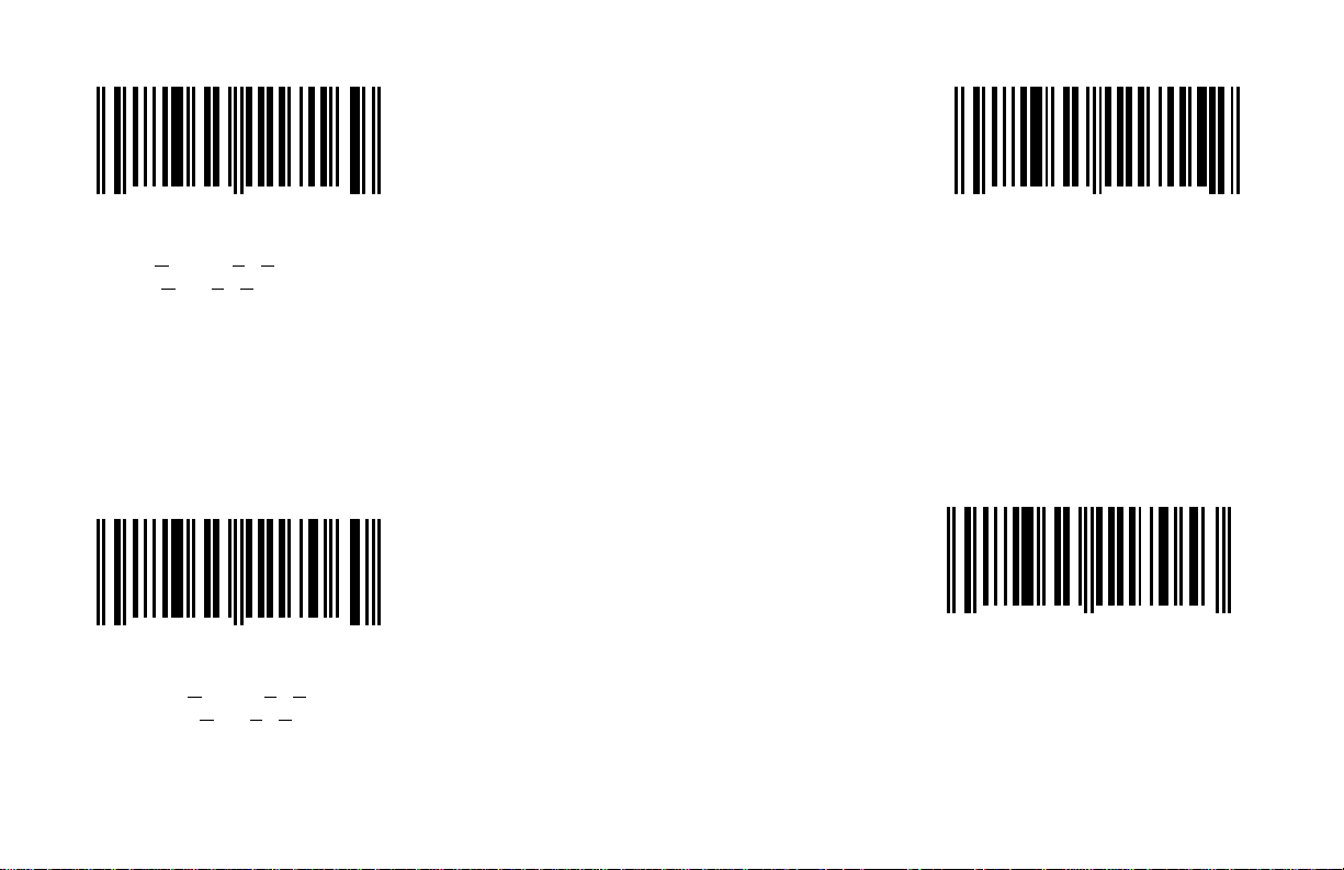
Enable RTS/CTS Handshaking *Character RTS/CTS
When this option is chosen, the scanner will
When this option is chosen, the scanner will
activate and deactivate its RTS signal on each
message that it transmits. This mode should
1 2 3 4 5 1 1 7 1 6
0
When this option is enabled, the scanner will
output a Request To Send (RTS) signal and
wait for a Clear To Send (CTS) signal before
any data is transmitted.
*Disable RTS/CTS Handshaking
1 2 3 4 5 1 1 7 0 6
0
When this option is chosen, the scanner will
not output a Request To Send (RTS) signal
and wait for a Clear To Send (CTS) signal
before any data is transmitted.
9
0
E - 14
1 2 3 4 5 1 1 7 1 5
0
activate and deactivate its RTS signal on
each character that it transmits.
Message RTS/CTS
1 2 3 4 5 1 1 7 0 5
0
normally be enabled for Sanyo registers.
2
3
Page 67
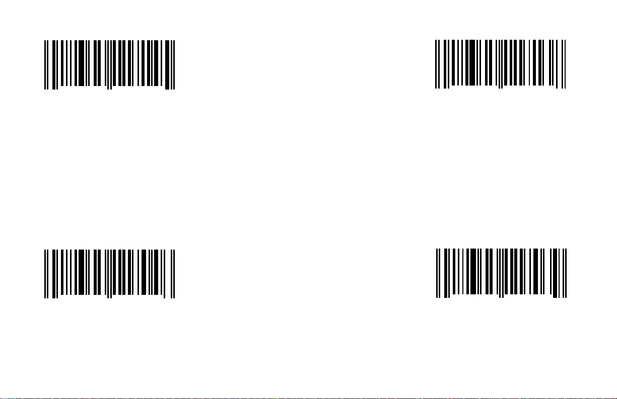
Enable XON/XOFF Handshaking Enable ACK/NAK
When ACK/NAK is enabled, the scanner will
not scan again unless an ACK (ASCII 06H) is
received after transmission of a bar code. If a
NAK (ASCII 15H) is received, the scanner will
1 2 3 4 5 1 1 7 1 4
0
When this option is enabled, the scanner will
stop transmission whenever an XOFF (ASCII
13H) is received. Transmission will resume after
an XON (ASCII 11H) is received.
*Disable XON/XOFF Handshaking *Disable ACK/NAK
1 2 3 4 5 1 1 7 0 4
0
When this option is chosen, the scanner will When this option is chosen, ACK/NAK
not stop transmission whenever an XOFF handshaking will not occur.
(ASCII 13H) is received.
5
6
E - 15
1 2 3 4 5 1 1 7 1 3
0
retransmit the bar code.
1 2 3 4 5 1 1 7 0 3
0
8
9
Page 68

Enable 5 Retries on ACK/NAK Time-out
1 2 3 4 5 1 1 2 1 3
0
When this option is enabled, the scanner will
transmit five times when an ACK/NAK communication time-out is reached.
*Disable 5 Retries on ACK/NAK Time-out
1 2 3 4 5 1 1 2 0 3
0
When this option is enabled, the scanner will
transmit one time when an ACK/NAK communication time-out is reached.
3
4
E - 16
Page 69

Section F
Keyboard Wedge Parameters
This section provides bar codes that can be chosen for various options available with keyboard emulation. This protocol is only available with
a version 17 scanner.
E/D = Enable/Disable
Enable Keyboard Wedge Emulation (F - 1) Reserved Keyboard (F - 4)
USA Keyboard (F - 1) E/D Caps Lock (F - 4)
Spain Keyboard (F - 1) E/D Alt Mode (F - 5)
Italy Keyboard (F - 2) E/D Reserved Wedge Function (F - 5)
Germany Keyboard (F - 2) Inter Scan Code Delay: None (F - 6)
France Keyboard (F - 2) Inter Scan Code Delay: 800 Fsec (micro) (F - 6)
UK Keyboard (F - 2) Inter Scan Code Delay: 7.5 msec (milli) (F - 6)
Belgium Keyboard(Swiss) (F - 3) Inter Scan Code Delay: 15 msec (F - 6)
XT Keyboard (F - 3) Transmit/Do Not Transmit F0H Break Code (F - 7)
AT Keyboard (F - 3) E/D MS6720 Extended Country Code Table (F - 7)
PS/2 Keyboard (F - 3) E/D MS700i/860i Extended Country Code Table (F - 8)
IBM 4700 Financial Keyboard (F - 4) Stand Alone or Single Ended Wedge Mode (F - 9)
E/D Stand Alone (F - 9)
F - i
Page 70

Enable Keyboard Wedge Emulation *USA Keyboard
If keyboard emulation is enabled, scan this
bar code to enable the keyboard type USA.
If keyboard emulation is enabled, scan this
bar code to enable the keyboard type Spain.
1 2 3 4 5 3 0 9 7 5
0
This option should be selected if the scanner will
provide keyboard emulation by converting the
scanned bar code data to the PC keyboard
scan code equivalent.
Application Notes:
For most applications, it will be desirable to disable line
feed transmission. (Pg. E - 11)
For non-USA keyboards, 10 mesc (Pg. C - 11) is probably
the best intercharacter delay.
For network system installations, tuning of the intercharacter
and inter scan code options may be required.
5 0
F - 1
1 2 3 4 5 3 1 7 6 0
Spain Keyboard
1 2 3 4 5 3 1 7 5 0
0
6
7
Page 71
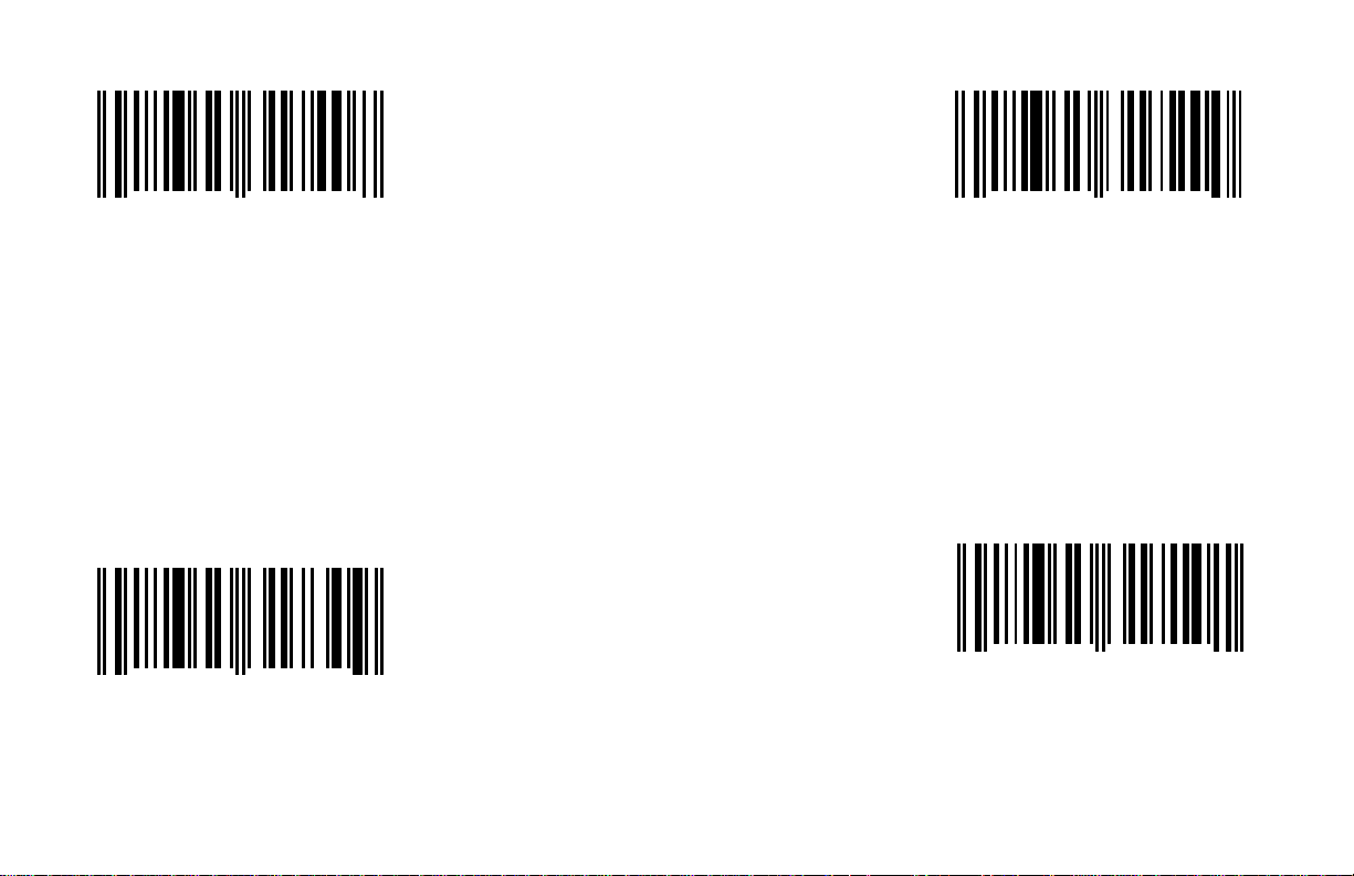
Italy Keyboard France Keyboard
If keyboard emulation is enabled, scan this
bar code to enable the keyboard type France.
If keyboard emulation is enabled, scan this
1 2 3 4 5 3 1 7 4 0
0
If keyboard emulation is enabled, scan this
bar code to enable the keyboard type Italy.
Germany Keyboard
1 2 3 4 5 3 1 7 3 0
0
If keyboard emulation is enabled, scan this
bar code to enable the keyboard type Germany.
8
9
F - 2
1 2 3 4 5 3 1 7 2 0
0
UK Keyboard
1 2 3 4 5 3 1 7 1 0
0
code to enable the keyboard type UK.
0
1
Page 72
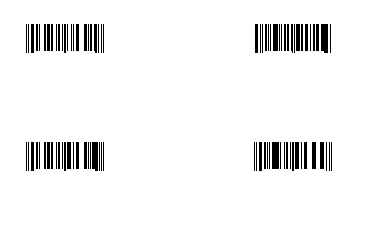
Belgium Keyboard (Swiss)* *AT Keyboard
(includes IBM® PS/2 and compatible models 50,
(includes IBM® PC and compatible models 30,
1 2 3 4 5 3 1 7 0 0
0
If keyboard emulation is enabled, scan this If using an AT computer, scan the above.
bar code to enable the keyboard type Belgium.
*(scan this code and enable extended country 55, 60, 80).
code table bar code pg. F-7 to activate Swiss
Keyboard mode).
XT Keyboard
1 2 3 4 5 2 1 7 0 5
0
If using an XT computer, scan the above.
2
0
F - 3
1 2 3 4 5 2 1 7 1 5
0
PS/2 Keyboard
1 2 3 4 5 2 1 7 2 5
0
If using a PS/2 computer, scan the above.
70, 8556).
9
8
Page 73
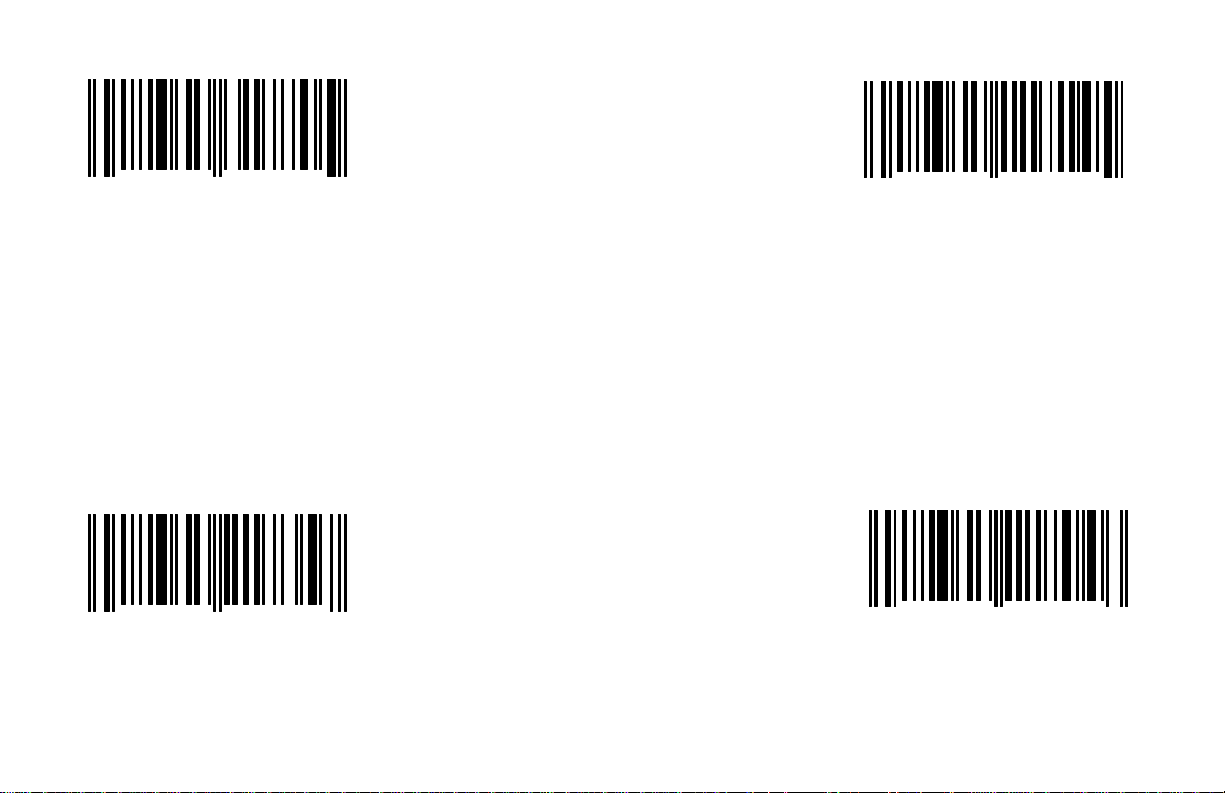
IBM® 4700 Financial Keyboard Enable Caps Lock
Automatically detects Caps
When this option is disabled, the Caps Lock
1 2 3 4 5 3 1 7 7 0
0
If using an IBM® 4700 Financial Keyboard,
scan the above.
5
1 2 3 4 5 1 1 7 1 4
0
AT Mode
PS/2 or XT Mode User-defined Caps
These modes may not work with all applications.
5
Locks status
Lock status
Reserved Keyboard
1 2 3 4 5 2 1 7 3 5
0
*Disable Caps Lock
1 2 3 4 5 1 1 7 0 4
7
F - 4
0
feature is not supported.
6
Page 74

Enable Alt Mode Enable Reserved Wedge Function
1 2 3 4 5 1 1 7 1 7
0
When this option is enabled, the scanner will
duplicate this keyboard sequence: Hold down
the Alt key; Type the decimal number that
corresponds to the appropriate character.
6
1 2 3 4 5 1 1 7 1 3
0
8
*Disable Alt Mode
1 2 3 4 5 1 1 7 0 7
0
Caution: If the host software application uses the Alt
key as a "Hot" key, make sure Alt mode is disabled.
7
F - 5
*Disable Reserved Wedge Function
1 2 3 4 5 1 1 7 0 3
0
9
Page 75
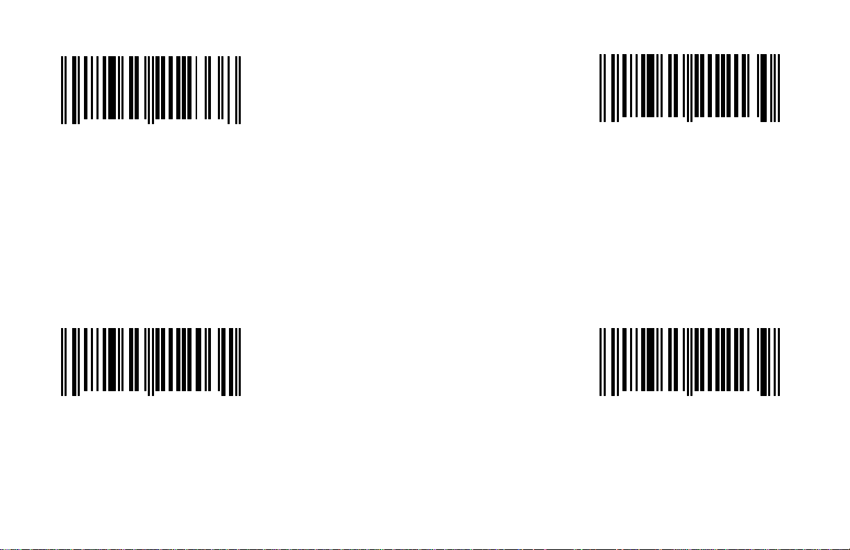
Inter Scan Code Delay: None Inter Scan Code Delay: 7.5 msec
of time between individual 9-bit scan codes.
1 2 3 4 5 2 1 2 1 3
1 2 3 4 5 2 1 2 3 3
0
If an inter scan code delay is not required, The time specified represents the amount
choose this option. of time between individual 9-bit scan codes.
*Inter Scan Code Delay: 800 FFsec (micro-seconds) Inter Scan Code Delay: 15 msec
8
0
This parameter may need to be adjusted for
operation with certain PC keyboard BIOS.
0
1 2 3 4 5 2 1 2 0 3
0
The time specified represents the amount The time specified represents the amount
of time between individual 9-bit scan codes.
This parameter may need to be adjusted for This parameter may need to be adjusted for
operation with certain PC keyboard BIOS. operation with certain PC keyboard BIOS.
1
F - 6
1 2 3 4 5 2 1 2 2 3
0
9
Page 76
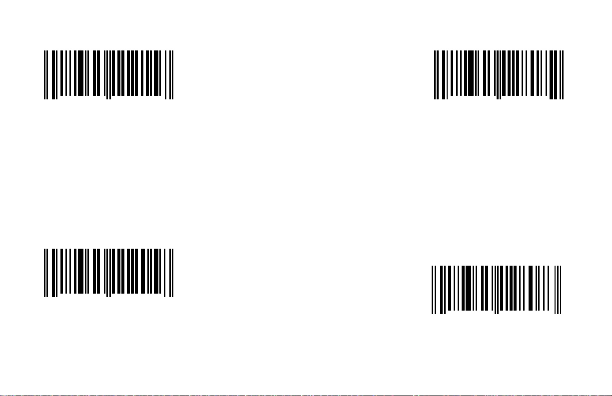
Do Not Transmit F0H Break Code
Enable MS6720 Extended Country Code
When this option is enabled, the scanner will
Disable MS6720 Extended Country Code
(AT and PS/2 keyboards) Table
1 2 3 4 5 1 1 2 1 5
0
When enabled, the scanner will not transmit
the F0H in the break-code sequence.
*Transmit F0H Break Code
(AT and PS/2 keyboards)
1 2 3 4 5 1 1 2 0 5
0
When this option is chosen, the scanner will
transmit the F0H in the break-code sequence.
7
access the extended country code table when
used with a corresponding primary country
code.
Table
8
F - 7
1 2 3 4 5 1 2 8 1 7
0
1 2 3 4 5 1 2 8 0 7
0
2
3
Page 77

Enable MS700i/860i Extended Country Code Table
1 2 3 4 5 1 1 7 1 3
0
When this option is enabled, the scanner will
access the extended country code table when
used with a corresponding primary country
code.
Disable MS700i/860i Extended Country Code Table
1 2 3 4 5 1 1 7 0 3
0
8
9
F - 8
Page 78

Stand Alone or Single Ended Wedge Mode* Enable Stand Alone
Some installations require a keyboard wedge scanner to connect to a
PC compatible keyboard port without an external keyboard. A cable that
has only the male keyboard connector that plugs into the motherboard
would be typically used. Enabling this mode allows the scanner to send
keyboard diagnostic completion codes and maintain the status of
variable keyboard functions such as num lock, caps lock and scroll lock.
*At this printing, this feature is not available for the MS6720.
This method was first developed to work through the auxiliary keyboard
port of an IBM 4614 Sure One POS terminal. It can also be used with
some, but not all notebook computers equipped with an external
keyboard port.
Application Test Note:
Due to variations in host systems, Metrologic cannot guarantee that a
stand alone scanner in single ended mode will work with your system. A
reliable test for compatibility would be to connect an external keyboard
to the notebook and power up the unit. If the notebook accepts data
from both the external keyboard and the built in keyboard, the notebook
is likely to work with the scanner in single ended mode.
1 2 3 4 5 1 1 2 1 6
0
If keyboard emulation is enabled, scan this
bar code to enable the Stand Alone mode.
Disable Stand Alone
1 2 3 4 5 1 1 2 0 6
0
4
5
F - 9
Page 79

Section G
Reserved Features
This section provides bar codes to select pre-encoded reserved functions. They execute a variety of special software features. However, they
should not be selected without written instructions from Metrologic.
E/D = Enable/Disable
E/D Reserved Code 4 (G - 1) E/D Reserved Code 30 (G - 9) E/D Reserved Code 47 (G - 18)
E/D Reserved Code 8 (G - 1) E/D Reserved Code 31 (G - 10) E/D Reserved Code 48 (G - 18)
E/D Reserved Code 9 ( G - 2) E/D Reserved Code 32 (G - 10) E/D Reserved Code 49 (G - 19)
E/D Reserved Code 14 (G - 2) E/D Reserved Code 33 (G - 11) E/D Reserved Code 50 (G - 19)
E/D Reserved Code 17 (G - 3) E/D Reserved Code 34 (G - 11) E/D Reserved Code 51 (G - 20)
E/D Reserved Code 18 (G - 3) E/D Reserved Code 35 (G - 12) E/D Reserved Code 52 (G - 20)
E/D Reserved Code 19 (G - 4) E/D Reserved Code 36 (G - 12) E/D Reserved Code 53 (G - 21)
E/D Reserved Code 20 (G - 4) E/D Reserved Code 37 (G - 13) E/D Reserved Code 54 (G - 21)
E/D Reserved Code 21 (G - 5) E/D Reserved Code 38 (G - 13) E/D Reserved Code 55 (G - 22)
E/D Reserved Code 22 (G - 5) E/D Reserved Code 39 (G - 14) E/D Reserved Code 56 (G - 22)
E/D Reserved Code 23 (G - 6) E/D Reserved Code 40 (G - 14) E/D Reserved Code 57 (G - 23)
E/D Reserved Code 24 (G - 6) E/D Reserved Code 41 (G - 15) E/D Reserved Code 58 (G - 23)
E/D Reserved Code 25 (G - 7) E/D Reserved Code 42 (G - 15) E/D Reserved Code 59 (G - 24)
E/D Reserved Code 26 (G - 7) E/D Reserved Code 43 (G - 16) E/D Reserved Code 60 (G - 24)
E/D Reserved Code 27 (G - 8) E/D Reserved Code 44 (G - 16) E/D Reserved Code 61 (G - 25)
E/D Reserved Code 28 (G - 8) E/D Reserved Code 45 (G - 17) E/D Reserved Code 62 (G - 25)
E/D Reserved Code 29 (G - 9) E/D Reserved Code 46 (G - 17) E/D Reserved Code 63 (G - 26)
E/D Reserved Code 64 (G - 26)
E/D Reserved Code 65 (G - 27)
G - i
Page 80
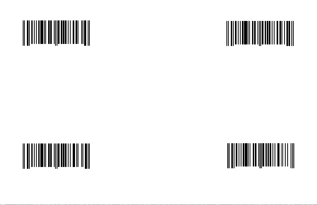
Enable Reserved Code 4 Enable Reserved Code 8
This option should not be enabled without
1 2 3 4 5 1 2 8 1 3
0
This option should not be enabled without
written instructions from Metrologic.
4
1 2 3 4 5 1 2 8 1 7
0
written instructions from Metrologic.
2
*Disable Reserved Code 4
1 2 3 4 5 1 2 8 0 3
0
*Disable Reserved Code 8
1 2 3 4 5 1 2 8 0 7
5
G - 1
0
3
Page 81
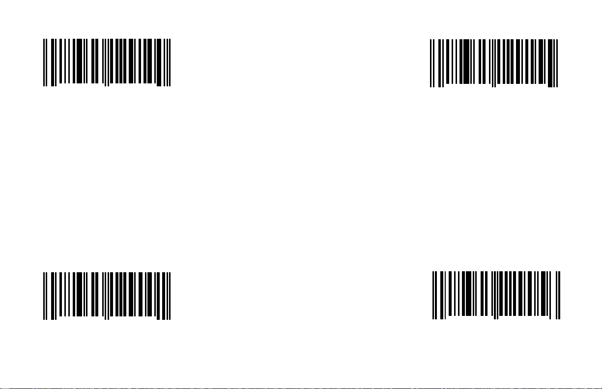
Enable Reserved Code 9 Enable Reserved Code 14
This option should not be enabled without
1 2 3 4 5 1 2 9 1 0
0
This option should not be enabled without
written instructions from Metrologic.
0
1 2 3 4 5 1 2 9 1 5
0
written instructions from Metrologic.
5
*Disable Reserved Code 9
1 2 3 4 5 1 2 9 0 0
0
*Disable Reserved Code 14
1 2 3 4 5 1 2 9 0 5
1
G - 2
0
6
Page 82
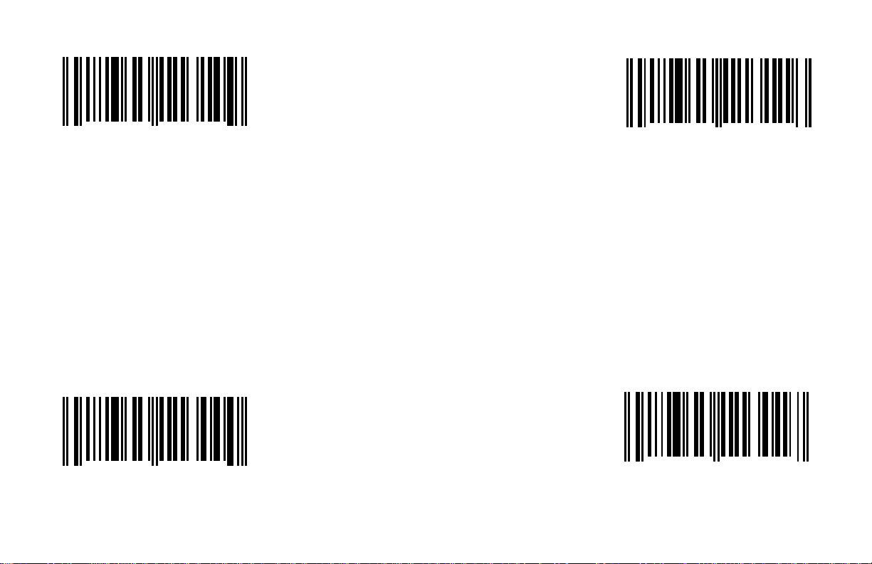
Enable Reserved Code 17 *Enable Reserved Code 18
This option should not be enabled without
1 2 3 4 5 1 1 3 1 0
0
This option should not be enabled without
written instructions from Metrologic. written instructions from Metrologic.
9
1 2 3 4 5 1 1 3 1 1
0
6
*Disable Reserved Code 17
1 2 3 4 5 1 1 3 0 0
0
Disable Reserved Code 18
1 2 3 4 5 1 1 3 0 1
0
G - 3
0
7
Page 83
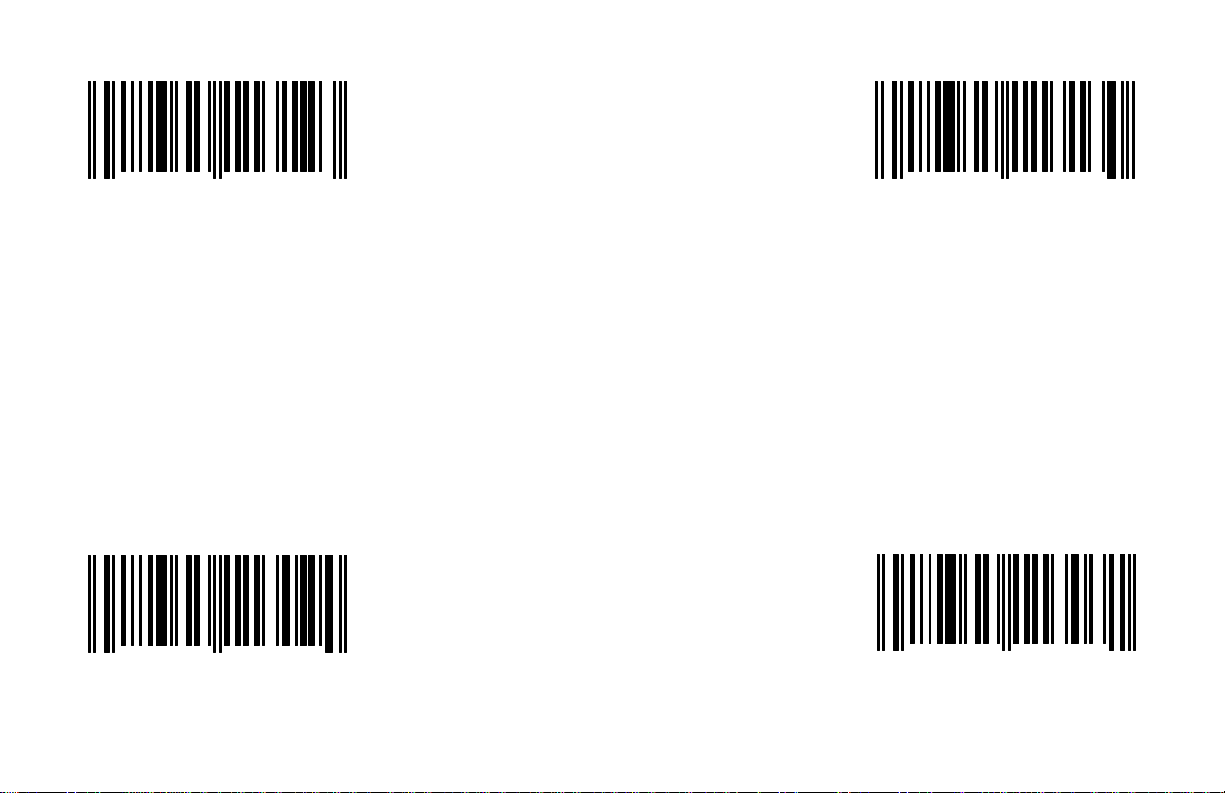
Enable Reserved Code 19 Enable Reserved Code 20
This option should not be enabled without
1 2 3 4 5 1 1 3 1 2
0
This option should not be enabled without
written instructions from Metrologic. written instructions from Metrologic.
*Disable Reserved Code 19 *Disable Reserved Code 20
1 2 3 4 5 1 1 3 0 2
0
3
4
G - 4
1 2 3 4 5 1 1 3 1 3
0
1 2 3 4 5 1 1 3 0 3
0
0
1
Page 84
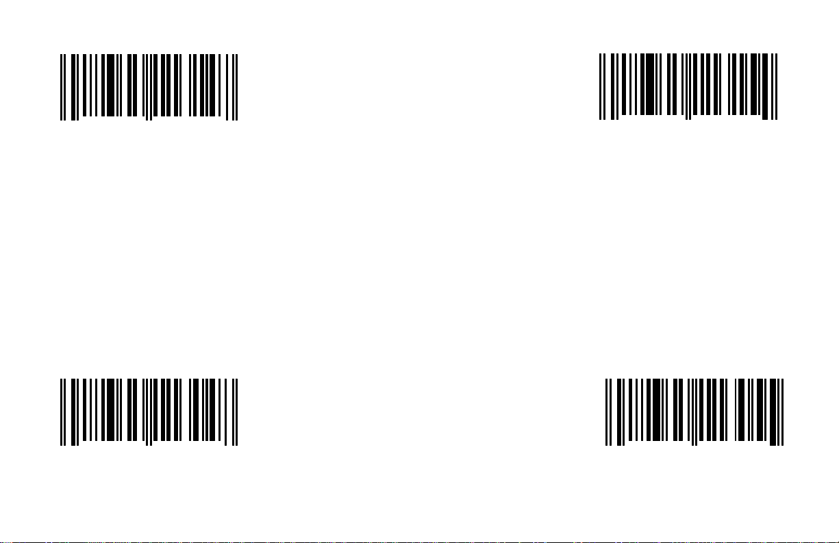
Enable Reserved Code 21 Enable Reserved Code 22
This option should not be enabled without
1 2 3 4 5 1 1 3 1 4
0
This option should not be enabled without
written instructions from Metrologic. written instructions from Metrologic.
*Disable Reserved Code 21 *Disable Reserved Code 22
1 2 3 4 5 1 1 3 0 4
0
7
8
G - 5
1 2 3 4 5 1 1 3 1 5
0
1 2 3 4 5 1 1 3 0 5
0
4
5
Page 85
Enable Reserved Code 23 Enable Reserved Code 24
This option should not be enabled without
1 2 3 4 5 1 1 3 1 6
0
This option should not be enabled without
written instructions from Metrologic. written instructions from Metrologic.
*Disable Reserved Code 23 *Disable Reserved Code 24
1 2 3 4 5 1 1 3 0 6
0
1
2
G - 6
1 2 3 4 5 1 1 3 1 7
0
1 2 3 4 5 1 1 3 0 7
0
8
9
Page 86
Enable Reserved Code 25 Enable Reserved Code 26
This option should not be enabled without
1 2 3 4 5 1 1 4 1 0
0
This option should not be enabled without
written instructions from Metrologic. written instructions from Metrologic.
*Disable Reserved Code 25
1 2 3 4 5 1 1 4 0 0
0
6
7
G - 7
1 2 3 4 5 1 1 6 1 2
0
*Disable Reserved Code 26
1 2 3 4 5 1 1 6 0 2
0
4
5
Page 87

Enable Reserved Code 27 Enable Reserved Code 28
This option should not be enabled without
1 2 3 4 5 1 1 6 1 3
0
This option should not be enabled without
written instructions from Metrologic. written instructions from Metrologic.
*Disable Reserved Code 27 *Disable Reserved Code 28
1 2 3 4 5 1 1 6 0 3
0
1
2
G - 8
1 2 3 4 5 1 1 6 1 4
0
1 2 3 4 5 1 1 6 0 4
0
8
9
Page 88
Enable Reserved Code 29 Enable Reserved Code 30
This option should not be enabled without
1 2 3 4 5 1 1 6 1 5
0
This option should not be enabled without
written instructions from Metrologic. written instructions from Metrologic.
*Disable Reserved Code 29
1 2 3 4 5 1 1 6 0 5
0
5
6
G - 9
1 2 3 4 5 1 1 6 1 6
0
*Disable Reserved Code 30
1 2 3 4 5 1 1 6 0 6
0
2
3
Page 89
Enable Reserved Code 31 Enable Reserved Code 32
This option should not be enabled without
1 2 3 4 5 1 1 6 1 7
0
This option should not be enabled without
written instructions from Metrologic. written instructions from Metrologic.
*Disable Reserved Code 31 *Disable Reserved Code 32
1 2 3 4 5 1 1 6 0 7
0
9
0
G - 10
1 2 3 4 5 1 1 9 1 0
0
1 2 3 4 5 1 1 9 0 0
0
1
2
Page 90
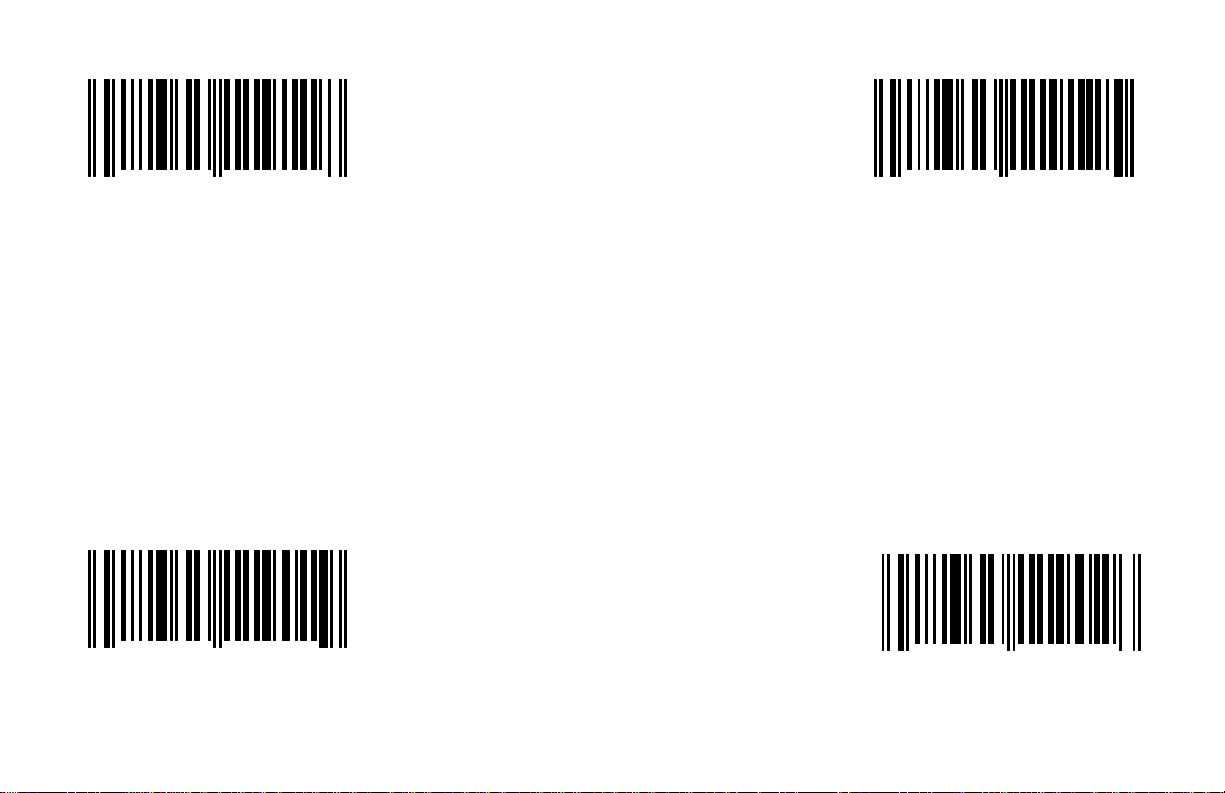
Enable Reserved Code 33 Enable Reserved Code 34
This option should not be enabled without
1 2 3 4 5 1 1 9 1 1
0
This option should not be enabled without
written instructions from Metrologic.
*Disable Reserved Code 33
1 2 3 4 5 1 1 9 0 1
0
8
9
G - 11
1 2 3 4 5 1 1 9 1 2
0
written instructions from Metrologic.
*Disable Reserved Code 34
1 2 3 4 5 1 1 9 0 2
0
5
6
Page 91

Enable Reserved Code 35 Enable Reserved Code 36
This option should not be enabled without
1 2 3 4 5 1 2 5 1 4
0
This option should not be enabled without
written instructions from Metrologic.
*Disable Reserved Code 35
1 2 3 4 5 1 2 5 0 4
0
0
1
G - 12
1 2 3 4 5 1 2 5 1 3
0
written instructions from Metrologic.
*Disable Reserved Code 36
1 2 3 4 5 1 2 5 0 3
0
3
4
Page 92
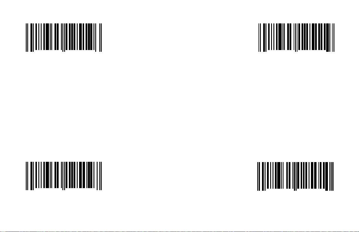
Enable Reserved Code 37 Enable Reserved Code 38
This option should not be enabled without
1 2 3 4 5 1 2 5 1 2
0
This option should not be enabled without
written instructions from Metrologic.
*Disable Reserved Code 37
1 2 3 4 5 1 2 5 0 2
0
6
7
G - 13
1 2 3 4 5 1 2 5 1 1
0
written instructions from Metrologic.
*Disable Reserved Code 38
1 2 3 4 5 1 2 5 0 1
0
9
0
Page 93
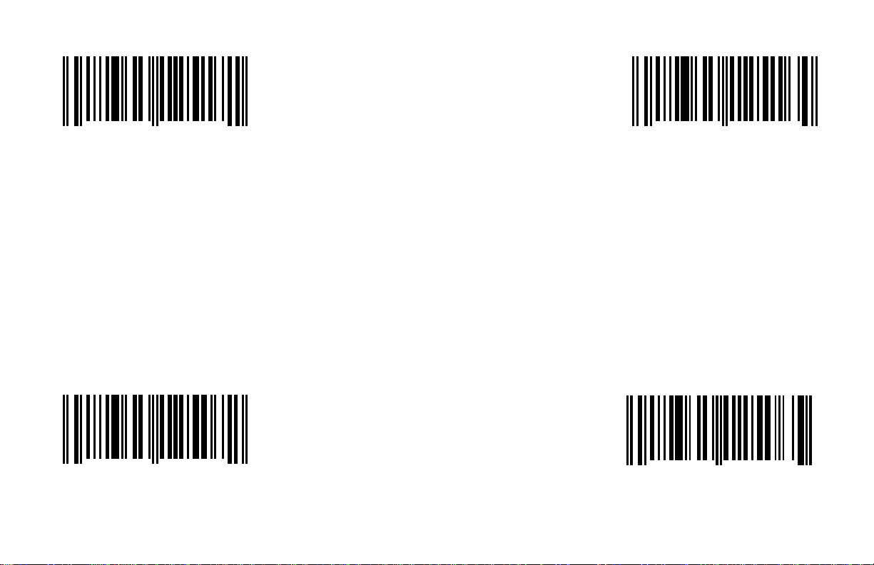
Enable Reserved Code 39 Enable Reserved Code 40
This option should not be enabled without
1 2 3 4 5 1 2 5 1 7
0
This option should not be enabled without
written instructions from Metrologic.
*Disable Reserved Code 39
1 2 3 4 5 1 2 5 0 7
0
1
2
G - 14
1 2 3 4 5 1 2 5 1 6
0
written instructions from Metrologic.
*Disable Reserved Code 40
1 2 3 4 5 1 2 5 0 6
0
4
5
Page 94
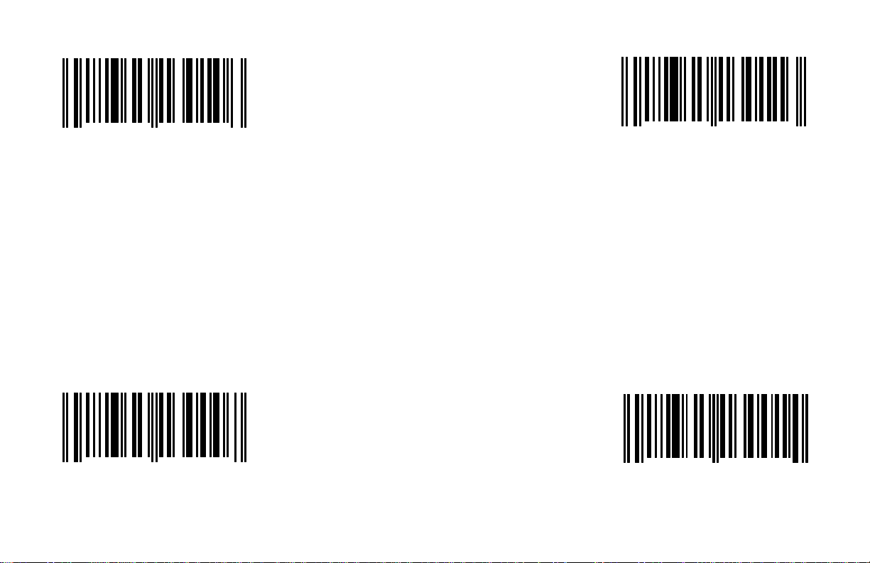
Enable Reserved Code 41 Enable Reserved Code 42
This option should not be enabled without
1 2 3 4 5 1 3 0 1 1
1 2 3 4 5 1 3 0 1 0
0
This option should not be enabled without
written instructions from Metrologic.
6
0
written instructions from Metrologic.
3
*Disable Reserved Code 41
1 2 3 4 5 1 3 0 0 0
0
*Disable Reserved Code 42
7
G - 15
1 2 3 4 5 1 3 0 0 1
0
4
Page 95
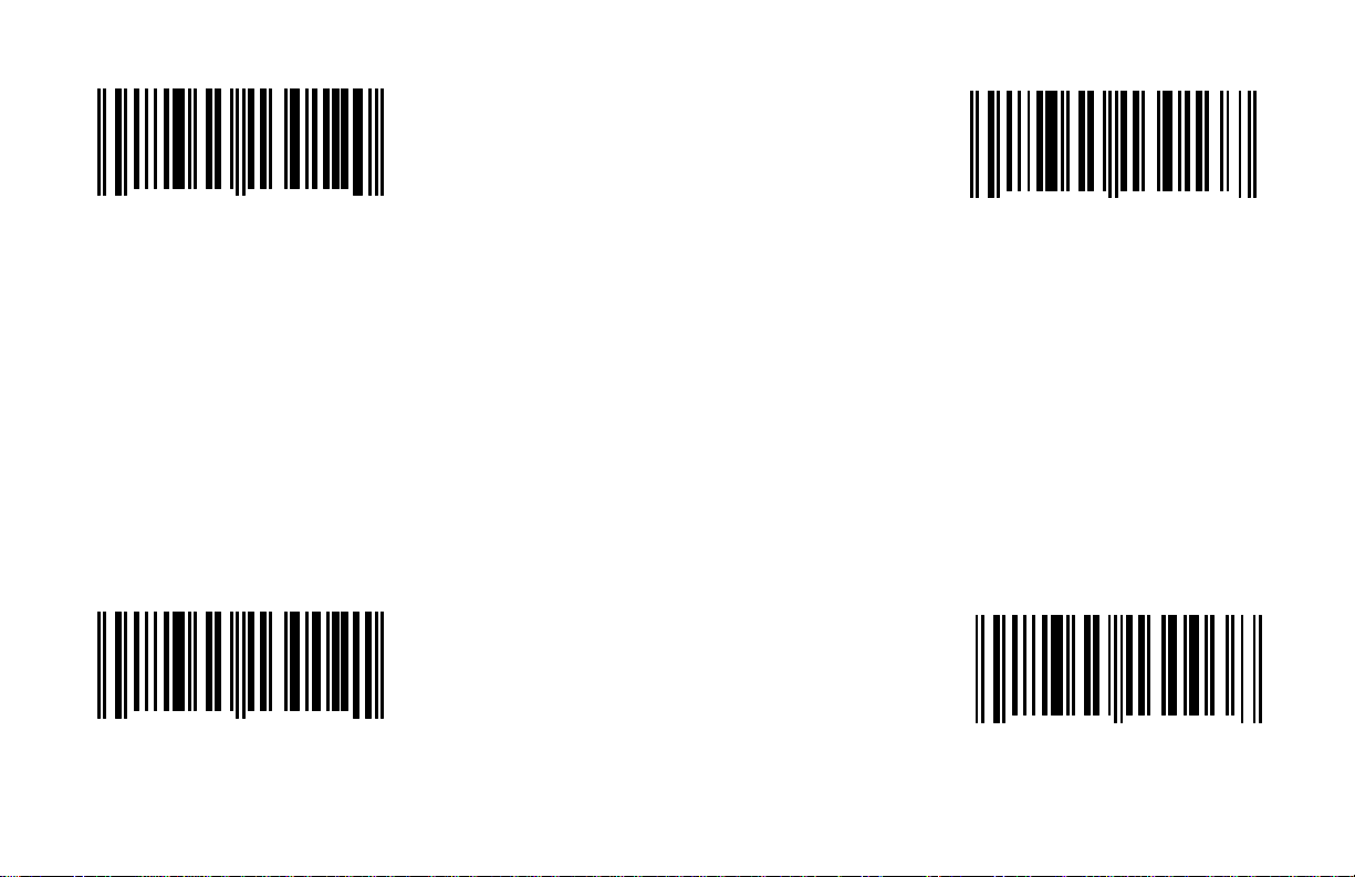
Enable Reserved Code 43 Enable Reserved Code 44
This option should not be enabled without
1 2 3 4 5 1 3 0 1 2
0
This option should not be enabled without
written instructions from Metrologic.
0
1 2 3 4 5 1 3 0 1 3
0
written instructions from Metrologic.
7
*Disable Reserved Code 43
1 2 3 4 5 1 3 0 0 2
0
*Disable Reserved Code 44
1
G - 16
1 2 3 4 5 1 3 0 0 3
0
8
Page 96
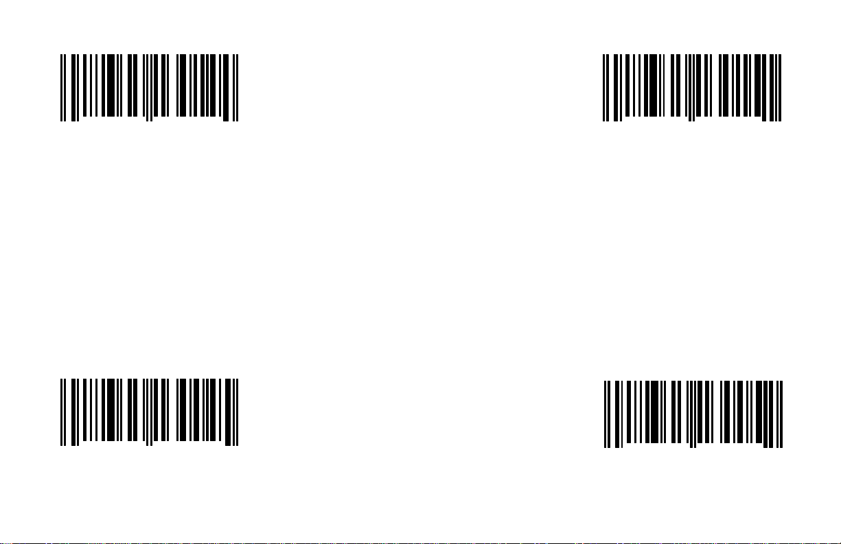
Enable Reserved Code 45 Enable Reserved Code 46
This option should not be enabled without
1 2 3 4 5 1 3 0 1 4
0
This option should not be enabled without
written instructions from Metrologic.
*Disable Reserved Code 45
1 2 3 4 5 1 3 0 0 4
0
4
5
G - 17
1 2 3 4 5 1 3 0 1 5
0
written instructions from Metrologic.
*Disable Reserved Code 46
1 2 3 4 5 1 3 0 0 5
0
1
2
Page 97

Enable Reserved Code 47 Enable Reserved Code 48
This option should not be enabled without
1 2 3 4 5 1 3 0 1 6
0
This option should not be enabled without
written instructions from Metrologic.
8
1 2 3 4 5 1 3 0 1 7
0
written instructions from Metrologic.
5
*Disable Reserved Code 47
1 2 3 4 5 1 3 0 0 6
0
*Disable Reserved Code 48
9
G - 18
1 2 3 4 5 1 3 0 0 7
0
6
Page 98
Enable Reserved Code 49 Enable Reserved Code 50
This option should not be enabled without
1 2 3 4 5 1 2 4 1 0
0
This option should not be enabled without
written instructions from Metrologic.
5
1 2 3 4 5 1 2 4 1 1
0
written instructions from Metrologic.
2
*Disable Reserved Code 49
1 2 3 4 5 1 2 4 0 0
0
*Disable Reserved Code 50
6
G - 19
1 2 3 4 5 1 2 4 0 1
0
3
Page 99
Enable Reserved Code 51 Enable Reserved Code 52
This option should not be enabled without
1 2 3 4 5 1 2 4 1 2
0
This option should not be enabled without
written instructions from Metrologic. written instructions from Metrologic.
*Disable Reserved Code 51 *Disable Reserved Code 52
1 2 3 4 5 1 2 4 0 2
0
9
0
G - 20
1 2 3 4 5 1 2 4 1 3
0
1 2 3 4 5 1 2 4 0 3
0
6
7
Page 100
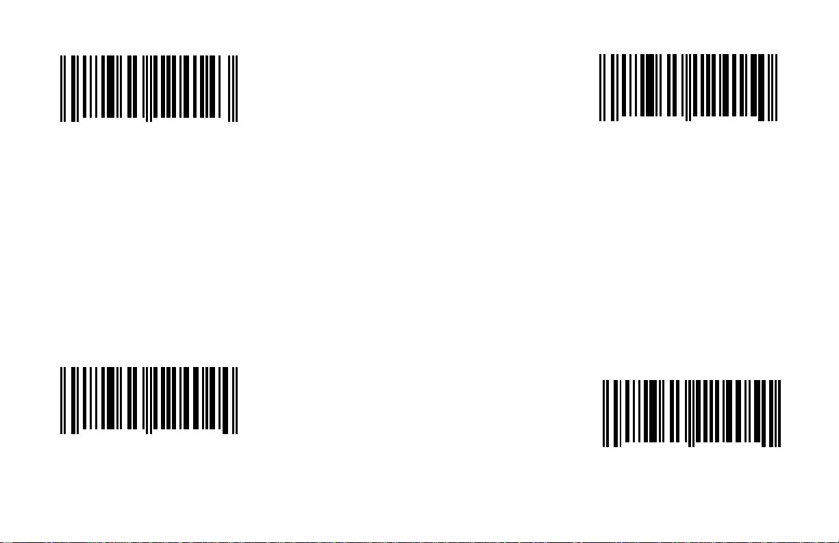
Enable Reserved Code 53 Enable Reserved Code 54
This option should not be enabled without
1 2 3 4 5 1 2 4 1 4
0
This option should not be enabled without
written instructions from Metrologic. written instructions from Metrologic.
*Disable Reserved Code 53
1 2 3 4 5 1 2 4 0 4
0
3
4
G - 21
1 2 3 4 5 1 2 4 1 5
0
*Disable Reserved Code 54
1 2 3 4 5 1 2 4 0 5
0
0
1
 Loading...