


RC series
Instruction Manual

Metrol Co., Ltd.
Model : RC-R02
Power : DC24V
R 001-A00052
CMIIT ID : 2012DJ3661
Made in Malaysia
FCC ID : AORMETROLRCR02
This device complies with
Part 15 of the FCC Rules.
Operation is subject to the
following two conditions:
1-
this device may not cause
harmful interference. and
2-
this device must accept
any interference received,
Including interference that
may cause undesired
operation.
Metrol Co., Ltd.
Model : RC-K3E
Power : 3.6V
R 001-A00026
CMIIT ID : 2012DJ3660
Made in Japan
FCC ID : AORMETROLRCK3E002
■Technical conformity marks
This device complies with Part 15 of the FCC Rules.
Operation is subject to the following two conditions:
1-this device may not cause harmful interference. and
2-this device must accept any interference received,
Including interference that may cause undesired operation.

www.baysupply.com
INDEX
1.
Before using
Terms of Warranty
Usage precautions
2.
Basic specification
3.
Software specification
Transmitter
Receiver
4.
Matching transmitter and receiver
5.
Parameter switch (DIP switch)
Details of parameter switch (DIP switch)
Details of LED display
6.
Transmission range when combining transmitter and receiver
7.
Receiver installation
. . . . . . . . . . . . . . . . . . . .
. . . . . . . . . . . . . . . . . . . .
. . . . . . . . . . . . . . . . . . . .
. . . . . . . . . . . . . . . . . . . .
. . . . . . . . . . . . . . . . . . . .
. . . . . . . . . . . . . . . . . . . .
. . . . . . . . . . . . . . . . . . . .
. . . . . . . . . . . . . . . . . . . .
. . . . . . . . . . . . . . . . . . . .
. . . . . . . . . . . . . . . . . . . .
P11−13
P14−16
P1−2
P3
P5−6
P7
P8
P9
P17
P19
8.
Transmitter installation
Stylus attachment
Installing the battery
Attachment of the transmitter to shank
Stylus centering adjustment
9.
Maintenance
10.
Troubleshooting
. . . . . . . . . . . . . . . . . . . .
. . . . . . . . . . . . . . . . . . . .
. . . . . . . . . . . . . . . . . . . .
. . . . . . . . . . . . . . . . . . . .
. . . . . . . . . . . . . . . . . . . .
. . . . . . . . . . . . . . . . . . . .
P27−28
P21
P22
P23
P24
P25

4
www.baysupply.com
1.
Before using
■Terms of Warranty
We endeavor to achieve zero claims and complaints rate with respect to product quality assurance.
Although malfunctions are a problem that comes before the warranty and even one should be
prevented, malfunctions cannot be prevented through our efforts alone. We would therefore like
to request that our customers have an understanding of the functions and specifications of
applicable products as indicated in our catalogs, instruction manuals and web site to ensure
that they are used properly under specified conditions.
Furthermore, applicable products are designed and manufactured primarily for general
industrial use.
Therefore, we would also like to request our customers to cooperate in employing a safe
design for preventing accidents, fires and the like through providing of fail-safe measures,
preventing operational errors and employing redundant safety designs.
1
Applicable products
The warranty defined below is applicable to products manufactured and sold by METROL (to
be referred to as the "applicable products").
2
Warranty period
The warranty for applicable products is valid for one year and three months from the original
delivery date to the location designated by the customer.
*The initial three months are assumed to be a preparation period until use of the products
following purchase.
3
Range of coverage
a.
A replacement product will be provided on an exchange basis or the malfunctioned product
will be repaired free of charge within the warranty period. If the product is or becomes
defective and that at the sole discretion of METROL, the defects due to faulty materials or
workmanship.
However, applicable products will not covered by the warranty in the case of the following
malfunctions even within the warranty period.
( I )
Malfunctions occurred due to use of a product in a manner that deviates from
standards, specifications, environments, usage procedures or usage precautions
described in the catalog, instruction manual or specifications.
(
II ) Malfunctions having occurred for reasons other than those attributable to the delivered
product.
( III ) Malfunctions having occurred due to modifications or repairs made by someone else
other than the Metrol representative.
(IV) Malfunctions or damage that results from external causes outside our control which
shall include accident fire disaster, other nature disaster or other force majeure.


2
www.baysupply.com
b.
The range of coverage is limited to warranty of the applicable product only, and any other
secondary loss or damage resulting from the malfunction of an applicable product is not
covered by the warranty.
c.
Please be aware that charges for service (including installation, de-installation on-site
confirmation and repairs) are not included in the price of products.
4
Applications
Applicable products are designed and manufactured as general-purpose products used in
ordinary industrial environments.
In the case of incorporating an applicable product in an apparatus, machine or system,
please confirm the suitability of the application along with any related standards, regulations
and restrictions.
With respect to the applications indicated below in particular, customers are requested to
conduct necessary tests on an actual product in advance after consulting with the
manufacturer regarding usage conditions and other details.
a.
Applications for which usage conditions or environment are outside those presumed by the
manufacturer or applications unable to be confirmed as being appropriate by the
manufacturer when using applicable products.
b.
Applications likely to have an effect on human life or property (such as nuclear power
equipment, transportation machinery or medical devices), applications used in public
utilities (such as electricity, gas or water lines), or applications applying correspondingly
thereto.
c.
Applications in harsh environments (special environments requiring heat resistance, vacuum
and the like)
*Although METROL believes that sound reliability in harsh environments is one of the
characteristics of our products, there are still cases in which it is difficult to ascertain actual
circumstances.
Since there is the potential for accidents in such cases, customers are requested to have an
understanding of protective structures, materials and so forth and provide additional covers
and other equipment as necessary.
5
Other matters
The contents of this catalogue, including specific models and, specifications, and any
other contents, are subject to change without notice at METROL’s sole discretion.
Although the utmost care has been taken in producing this manual, the manufacturer is
not responsible for any damages incurred as a result of clerical or other errors in this
manual.

3
www.baysupply.com
1.
Before using
■
Usage precautions
1
Battery
The transmitter comes with two 1 / 2AA size lithium metal batteries (non-rechargeable).
Please dispose of used batteries in accordance with laws and regulations relating to the
environment and safety regulations in your area. Do not attempt to recharge these batteries.
When replacing the battery, confirm that the battery is of the recommended or applicable
type, and confirm that the battery is inserted while correctly aligning the electrodes in
accordance with the procedure described in this manual and the indications on the product.
Please refer to the instruction manual of the battery manufacturer for guidelines relating to
specific battery applications, safety and disposal.
・Please confirm that all batteries are inserted with the electrodes correctly aligned.
・Do not store batteries in locations subject to direct sunlight or rain.
・Do not allow the battery to be heated or incinerated.
・Do not intentionally discharge the battery.
・Do not allow the battery to be short-circuited.
・Do not disassemble the battery, subject the battery to excessive pressure, drill holes in the
battery or allow it to be deformed.
・Take precautions so that the battery is not accidentally swallowed. Store the battery in a
location out of the reach of children.
・Do not allow the battery to become wet.
2
Glass window
The transmitter has a glass window. In the case the glass window should happen to be
broken, handle the product carefully to prevent injury.
3
Installation
Please confirm that the following guidelines are strictly observed at the responsibility of the
person performing installation work to ensure that the product functions properly.
・Please install while placing the interface at an adequate distance from electrical noise
generation sources such as transformers or servo amplifiers.
・Connect all 0V / ground connections to a central ground terminal on the machine.
(
The grounding and shielded cables of all devices can be connected to ground.)
This is extremely important, and failure to do so can cause the generation of an electrical
potential between the product and ground.
・Connect all shields as indicated in the user's guide.
・Place cables at an adequate distance from large-current cables such as motor and other
power cables as well as high-speed data cables.
・Try to keep cable lengths as short as possible at all times.
4) Product usage
Use of this product in a manner other than that specified by METROL may cause a decrease
in the guaranteed performance and functions of the product.

4
www.baysupply.com
NOTE

5
www.baysupply.com
Communication
Bi-direction
Antenna
On board chip antenna
Contact signal
1 point NC
LED display
1 LED(Red:signal output of transmitter)
Power source
1/2AA thionyl chloride battery
Once battery is installed to the battery holder, the current consumption starts.
For long-term storage, it is recommendable to remove the battery from the battery holder.
Weight(excluding a shank)
With battery:290g / Without battery:280g
Battery life(calculation)
Standby mode : 200 days
5% use(72min/day) : 87 days
Continuous use
: 180 hours
Communication
Bi-directional
Antenna
1/4λ dipole antenna
Transmission range
Max. 15m
ID control
Receiver performs communication exclusively with the transmitter using its ID number
after coupling operation.
LED display
4 LEDs (Blue:Power, Orange : Battery alarm, Green:Communication status, Blue :
Skip signal output of transmitter)
Parameter switch
DIP Switch on board 8bit
Output signal
φ7.2/14 cores oil resistant cable with watreproof connector
Input : power source (DC 24V), M code(power ON/OFF signal)
Output : Skip signal (Probe status 2a), Probe status1, Battery alarm, Probe status 2b)
Response speed
Min.1ms
(From transmitter turns ON until receiver skip signal activates. However, this depends on communicatin status)
Power supply voltage
24V±10%
Current consumption
Max.100mA(24V ± 10%)
Data rate
2MbpS.
RF put
Max. 0dBm (without antenna)
Sensitivity
Max. -82dBm (without antenna)
Protective structure
IEC IP67
Frequency range
2400 - 2480 MHz
No. of channels
37
Channel occupation width
2MHz
Modulation
FSK (DSSS)
2.
Basic specification
The transmitter communicates with the receiver using 2.4GHz ISM band.
The receiver receives touching signal, battery alarm signal and communication alarm signal from
the transmitter and outputs the decoded signals to CNC controller through the cable.
This system gains FCC, CE, TELEC (JAPAN), SRCC (CHINA) and RoHS, WEEE certification.
2-1
Common specification
2-2
Transmitter specification
2-3
Receiver specification

6
www.baysupply.com
4.7kΩ
BLUE
BLUE / BLACK
VIOLET
VIOLET / BLACK
GREEN
GREEN / BLACK
WHITE
BROWN
YELLOW
GRAY
ORANGE
+24V
PROBE STATUS 1
+24V
LOW BATTERY
+24V
ERROR
MACHINE START +
MACHINE START 0V
SKIP +
SKIP 0V
PROBE STATUS 2b
RED
BLACK
GREEN / YELLOW
+24V (12V-30V)
0V
MACHINE GROUND
2-3-1
Wiring diagram
2-3-2
LED display
System status is displayed with four LED shown at right.
・Power LED :Indicates status of power supply.
・Com. LED :Indicates communication status between transmitter and receiver.
:Communication status decreased or interrupted, or searching for connection
・Batt. LED :Indicates battery status of transmitter.
・Touch LED :Indicates the signal output of the transmitter.
OFF :Battery normal
OFF:Contact OFF
:Standby (approxmately 60 seconds after
machine tool power is switched on)
:Normal power supply status
:Normal communication status
:Recommed replacing the battery
(
low residual charge)
:Battery dead
*During the matching procedure, it indicates completion of matching mode (refer to P9)
(
transmitter signal output OFF)
:Contact ON
(
touch probe signal output ON)

7
www.baysupply.com
3.
Software specification
3-1
Transmitter
Transmitter has 3 modes.
1
Sleep mode
When M code (power ON signal) does not exist, transmitter operates in the Sleep mode to
suppress power consumption.
Transmitter periodically attempts to make communication witht the receiver.
Transmitter and receiver communicate with each other and exchange data every 14 - 27
seconds, if the communication is possible.
In this communication, transmitter sends the battery alarm signal to the receiver while receiver
sends the channel information to transmitter.
In case it stays incommunicable for 30 seconds or longer, it changes channels automatically.
When the transmitter is incommunicable with the receiver, it attempts to communicate by
changing channels.
Once the communication is established, its functions will be recovered within 4 seconds.
2
Measuring mode
Once the transmitter received M code (power ON signal) from the receiver, it enters Measuring
mode.
In this Measuring mode, transmitter communicates with receiver every 2ms.
In case the communication is not successful, the transmitter immediately changes channels.
The LED of the transmitter turns on when the contact touches a workpiece.
The transmitter enters Sleep mode automatically if it stays incommunicable for 1 minute.
Even in this case, the transmitter returns to Measuring mode soon after M code (power ON
signal) is sent from the receiver.
3
Matching mode
This mode is the initial setting.
In this wireless communication system, the transmitter stores ID number.
By using ID number, it performs matching with the receiver so that the receiver stores ID.
Once ID number is stored in the receiver, it performs communication exclusively and is never
affected by any other communication systems.
This ID number (transmitter) is stored nonvolatile.
Note: Matching is necessary every time transmitter is exchanged.

8
www.baysupply.com
LED
LED display
Output signal
Power LED (Blue)
Power supply status(Lit: Normal, Flashing: in preparation)
Com. LED (Green)
Communication Status(Lit: Normal, Flashing: Bad communication)
Error (Lit: ON )
Batt. LED (Orange)
Battery Status (Flashing: Low battery, Lit: Dead battery)
Error (Flashing: ON )
Touch LED (Blue)
Output signal from transmitter(Lit: Contact ON, Unlit: Contact OFF)
Probe status, skip
3-2
Receiver
Receiver has 3 modes.
1
Sleep mode
Receiver watches 2400-2480 MHz range anytime and find out the empty channel.
It waits until M code (power ON signal) is sent, continuously sending radio wave state (empty
channel information) to the transmitter.
If the communication with the transmitter is successful, the Com. LED (Green) of the receiver is
turned on.
If the communication cannot be achieved, the Com. LED (Green) flashes.
In the Sleep mode, no alarm signal is output to a control device even if the communication is
abnormal.
Batt. LED (Orange) flashes or lights up when the battery runs out, but the receiver does not
output alarm signal.
2
Measuring mode <After receiving Measuring ON Signal (M code)>
After the receiver sends M code (power ON signal) to the transmitter, receiver and other system
enters the Measuring mode.
Then it waits for the sensor ON signal from transmitter. At the same time, it prepares for
sending all alarm signal to control device.
All LEDs become active.
* It depends on battery state at the time of input of M code, and is effective only for 10 seconds.
When M code (power OFF signal) is sent from a control device, receiver transmits it to the
transmitter. Then both receiver and transmitter enter the Sleep mode from the Measuring mode.
3
Matching mode
This mode is the initial setting.
The receiver stores the ID number of transmitter in order not to be affected by any similar
signals.
This ID number (transmitter) is stored nonvolatile.
Note: Matching is necessary every time the transmitter is exchanged.
*

9
www.baysupply.com
Power. LED
Com. LED
Batt. LED
Touch. LED
LED Flashing/
LED Flashing
LED Flashing
LED OFF
LED ON
1 2 3 4 5 6 7 8
Parameter switch
1 2 3 4 5 6 7 8
Power. LED LED Flashing/
LED ON
Com. LED LED Flashing
Batt. LED LED OFF
Touch. LED LED OFF
4.
Matching transmitter and receiver
It is necessary to match the transmitter and receiver when first installing the system.
Matching is also required when replacing either the transmitter or the receiver.
Matching can be performed anywhere within the range of movement of the system.
1
Receiver matching procedure
1)
Remove the cover of the receiver.
2)
Switch the parameter switch #8 (DIP switch) on the receiver to OFF.
Parameter switch
ON
2
Transmitter matching procedure
1)
Remove the cover of the transmitter and affix it again (Restart the transmitter).
① Remove the battery cover
with a screwdriver or coin
2)
Matching is completed when the Batt. LED lights.
3
Matching mode completion procedure
1)
Switch the parameter switch (DIP switch) #8 on the receiver to OFF.
2)
Complete the matching procedure by attaching the receiver cover.
Note : The matching procedure is performed to record the transmitter ID number in the receiver and
prevent interference by other radio signals.
Once the matching procedure has been performed, further matching is not required provided
the transmitter is not replaced (or repaired).
②Reinsert the battery
OFF
③
Affix the battery cover

10
www.baysupply.com
NOTE

10
www.baysupply.com
Parameter switch No.
ON/OFF
Output signal
Description
1
OFF
PROBE STATUS 1
LEVEL output
ON
PROBE STATUS 1
PULSE output
2
OFF
PROBE STATUS 1
NO (Nomally open)
ON
PROBE STATUS 1
NC (Nomally close)
1 = OFF Sensor ON Sensor OFF
2 = ON
OFF
ON
1, 2 = ON
40ms
OFF
ON
1, 2 = OFF Sensor ON
OFF
Sensor OFF
ON
1 = ON
2 = OFF
OFF
ON
40ms
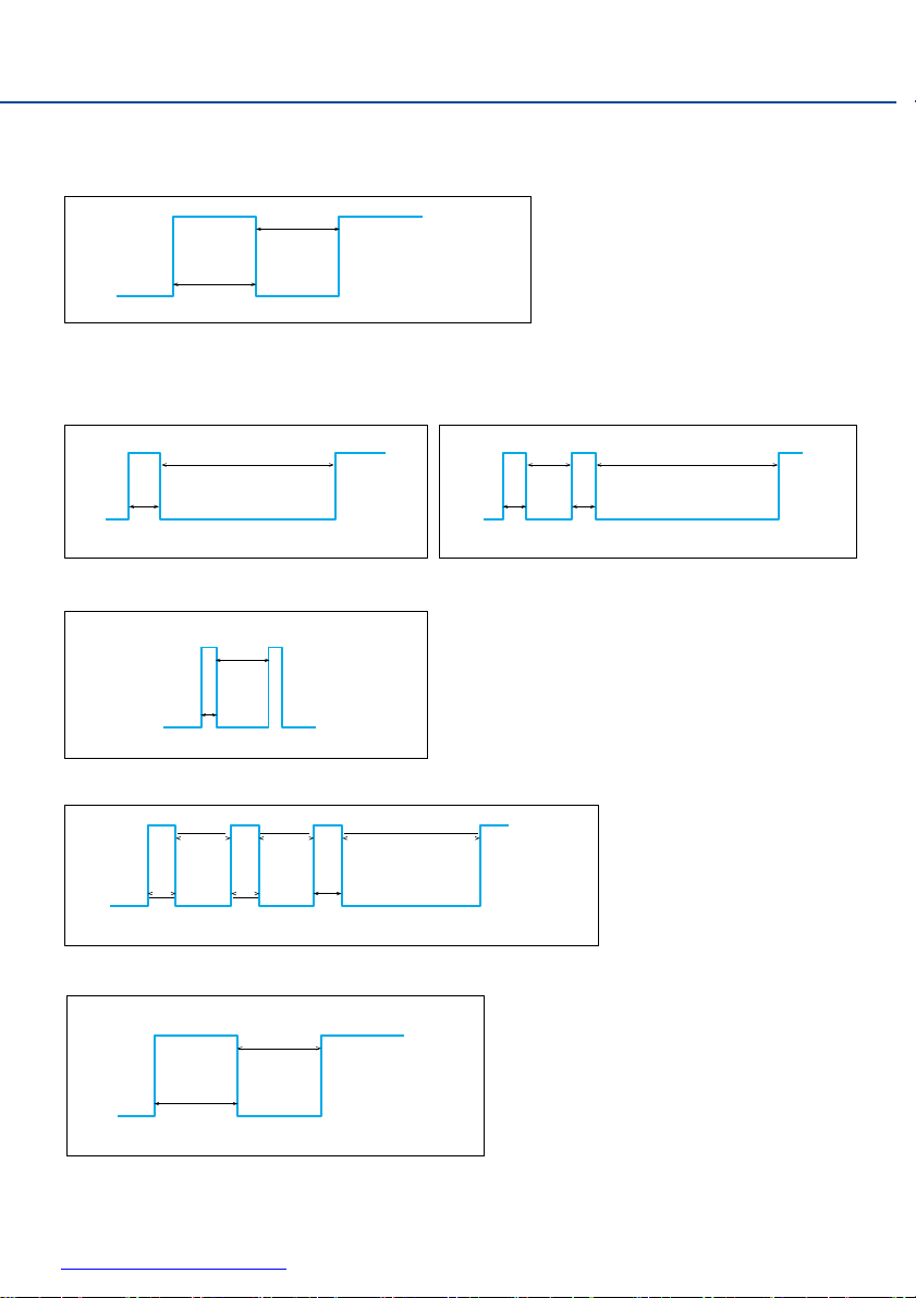
5.
Parameter switch (DIP switch)
5-1
Details of parameter switch (DIP switch)
PROBE STATUS1
PROBE STATUS 2a, 2b
LOW BATTERY NC (Nomally close)
ERROR NC (Nomally close)
PULSE
NC NC
(Nomally close)
PULSE
(Nomally close)
ON
1 2 3 4 5 6 7
LEVEL
NO NO
(Nomally open)
LEVEL
(Nomally open)(Nomally close)
Note: The waveform is the signal output after M code (power ON signal) is applied.
NC
PULSE
Matching mode ON
MACHINE START LEVEL
Matching mode ON
Mode changeover
switch
8

12
www.baysupply.com
Parameter switch No.
ON/OFF
Output signal
Description
3
OFF
PROBE STATUS 2a, 2b
LEVEL output
ON
PROBE STATUS 2a, 2b
PULSE output
4
OFF
PROBE STATUS 2a, 2b
NO (Nomally open)
ON
PROBE STATUS 2a, 2b
NC (Nomally close)
Parameter switch No.
ON/OFF
Output signal
Description
5
OFF
LOW BATTERY
NO (Nomally open)
ON
LOW BATTERY
NC (Nomally close)
Parameter switch No.
ON/OFF
Output signal
Description
6
OFF
ERROR
NC (Nomally close)
ON
ERROR
NO (Nomally open)
6 = OFF
Error occured
OFF
ON
6 = ON
Error occured
OFF
ON
5 = OFF Battery dead
OFF
ON
5 = ON Battery dead
OFF
ON
3 = OFF
Sensor ON Sensor OFF
4 = ON
OFF
ON
3, 4 = ON
40ms
OFF
ON
3, 4 = OFF
Sensor ON
Sensor OFF
OFF
ON
3 = ON
4 = OFF
OFF ON
40ms
Probe status 2a = Skip signal

13
www.baysupply.com
Parameter switch No.
ON/OFF
Output signal
Description
7
OFF
MACHINE START
PULSE input
ON
MACHINE START
LEVEL input
Parameter switch No.
ON/OFF
Description
8
OFF
Normal mode
ON
Matching mode
7 = OFF
20ms
≦
H
L
10ms
≦
1st PULSE 2nd PULSE 3rd PULSE
M code (Measuring start) M code (Measuring finish)
M code (Measuring start)
7 = ON
M code (Measuring start) M code (Measuring start)
H
L
M code (Measuring finish) M code (Measuring finish)
5. Parameter switch (DIP switch)
Note: All parameter switches (DIP switches) were in OFF position at the factory default
14
www.baysupply.com
200ms
Repeat
OFF
200ms
ON
160ms
160ms
440ms
Repeat
OFF
80ms
80ms
80ms
11ms
Repeat
OFF
1ms
ON
160ms
1680ms
Repeat
OFF
80ms
80ms
ON 1700ms
Repeat
OFF
300ms
500ms
ON
Repeat
OFF
500ms
5-2
Details of LED display
1.
Power LED flashing
2.
Com. LED flashing
1)
Transmitting NG 2) Transmitting NG
3)
Unstable communication in Measuring mode: early stage
4)
Incommunicable in Measuring mode:output the error signal
5)
Inside memory problem

15
www.baysupply.com
200ms
ON
Repeat
OFF
200ms
ON OFF Sensor ON
Sensor OFF
ON
200ms
Repeat
OFF 200ms ON
500ms
Repeat
OFF 500ms
ON
OFF
Matching complete
DIP switch #8 OFF
ON 840ms
Repeat
OFF 160ms ON
420ms
Repeat
OFF 80ms
5. Parameter switch (DIP switch)
6)
Matching phase
Seeking for the channel Matching complete
3.
Batt. LED flashing
1)
Matching phase
2)
Inside memory problem
4.
Touch LED
1)
Inside memory problem

16
www.baysupply.com
easuring start
PROBE STATUS 2b
Max 50V 500mA
0V
SKIP +
Max 50V 500mA
SKIP 0V
4.7kΩ
MACHINE START +
Max 70mA
MACHINE START 0V
+24V
Max 55V 50mA
ERROR
+24V
Max 55V 50mA
LOW BATTERY
+24V
Max 55V 50mA
PROBE STATUS 1
4.
PROBE STATUS 1
ERROR
I/O circuit
LOW BATTERY
MACHINE START
PROBE STATUS 2a (SKIP)
5.
Output waveform of the receiver
Machine ON
M code
(M
easuring start restoration (Measuring complete) (Measuring start)
Receiver
ready
Sensor OFF
)
Sensor ON
PROBE STATUS 2b
Commnucation
Communication
error
Battery dead
M code
10 sec. after M code
M code
(M
PROBE
STATUS1
LOW
BATTERY
ERROR
OFF
ON
OFF
ON
OFF
ON
SKIP(PROBE
STATUS 2a) ON
Note: These waveforms are output when all parameter switches (DIP switches) are in OFF position at
OFF
the factory default setting.
)
Battery
exchange

17
www.baysupply.com
*
Receiver
Transmitter
*
External installation
The antenna should be inside
of the splash guard in the case of
installing the receiver externally.
Workpiece
Internal
installation
Numerical control
(NC) device
*Install the receiver so that the antenna
is at not less than 30mm away from metals.
Transmission range when conbining transmitter and receiver
6.
Install the receiver at a location so that it can maintain communication over the movement range
of the transmitter.
RC sensor series are uninterrupted by any obstacles in between the transmitter and reciver.
Use the communication LED display of the receiver as a reference for determining the optimum
installation position.

18
www.baysupply.com
NOTE

18
www.baysupply.com
31.2
7.
Receiver installation
Inside
■
For external installation
φ
10.5
machine
Outside
machine
7.5
50
2-φ6.6
Splash guard
Recommended monting holes
■
For internal installation
Splash guard
Inside
2-φ6.6
50
Recommended monting holes
machine
Outside
machine
Splash guard
machine
■
Attachment of direct cable
•
Since the connector provides a waterproofing function when connected, insert the
connector securely and tighten the clamp nut.
•
Install the cable at an adequate distance away from electromagnetic noise generation
sources.
•
Always make sure to connect the cable to ground when connecting.
Inside
Outside
machine
Splash guard

20
www.baysupply.com
NOTE

20
www.baysupply.com
2. Tighten using the hexagonal
wrench and spanner.
1. Insert the stylus
Hexagonal wernch 0.89mm
Spanner S907
8.
Transmitter installation
8-1
Stylus attachment (RC-K3E)

www.baysupply.com
22
1.
Remove the battery cover
with a flat-head screwdriver or coin.
2.
Insert the battery and
attach the battery cover.
8-2
Installing the battery
・Confirm the alignment of the battery electrodes when inserting the battery.
・Does not function properly if a dead battery is mistakenly inserted into the transmitter.
・Do not allow coolant or cuttings to get inside the battery case.

23
www.baysupply.com
±0.1
2-M4
For fixing transmitter
(corn point fixing screws)
4-M4 (4 magnification)
For centering transmitter
(flat-tipped fixing screw)
17.5
≦
Mounting part of the shank
3
+0.01
φ
11
0
G
8.
Transmitter installation
8-3
Attachment of the transmitter to shank
1.
Attach the shank to the transmitter.
2.
Tighten two transmitter fixing
screws (corn point fixing screws)
with a hexagonal wrench.

www.baysupply.com
24
1.
Adjust centering by pushing and pulling
four flat-tipped fixing screws for transmitter
centering adjustment with lever type dial gauge
or similar tool and fasten them after adjusting.
2.
Tighten two transmitter fixing
screws (corn point fixing screws).
Lever type dial gauge
8-4
Stylus centering adjustment (mainly for RC-K3E)
Caution:It is necessary to recheck the centering adjustment if the transmitter has been dropped.
Absolutely never strike the transmitter when adjusting centering.

25
www.baysupply.com
1. Remove the battery cover
with a flat-bladed screwdriver or coin.
2. Take out the battery to replace it.
Be careful so that water and oil do not
get inside battery case when replacing the battery.
3. Before attaching the battery
cover, confirm that the battery
cover seal (O ring) is attached to
the groove of the battery case.
9.
Maintenance
■Cleaning the transmitter
Wipe the window of the transmitter with a clean cloth to remove any cuttings and other
debris such as coolant. Clean the transmitter regularly to maintain the signal transmission
capabilities of the transumitter in the optimum state.
■
Battery replacement
Caution:
・Confirm that the electrodes are correctly aligned when replacing the battery.
・Does not function properly if a worn down battery is mistakenly inserted into the probe.
・Do not leave a worn down battery installed in the transmitter.
・Confirm that the battery cover seal (O ring) has not been removed and use caution to prevent
it from being damaged.
・Be careful so that coolant or cuttings do not get inside battery case when replacing the
battery.
・Before attaching the battery cover, check to make sure there is no damage or debris on the
seal and its contact surface.
・Refer to page 3 for information on safe use of the battery.
・After having replaced a worn down battery, wait for at least 15 seconds before inserting a
new battery.

www.baysupply.com
26
NOTE

27
www.baysupply.com
Problem
Possible Cause
Corrective Action
Transmitter power
does not come on.
Dead battery
Replace the battery.
Use of battery other than
recommended battery
Replace the battery.
Battery is installed improperly
Check the alignment of
the electrodes of the battery.
The time the battery has been
removed is too short, preventing
the transmitter from resetting.
Wait for at least 15 seconds
before installing a new battery.
Tranmitter does
not operate even
when the measurement cycle is
executed.
Transmitter does not switch to the
Measuring mode.
Check whether the M code output
(power ON signal) of the control device
is pulse or level.
Receiver is set to pulse input as the
factory default settings. In case of
level output, turn on the DIP switch
No.7 of the receiver to set to level input.
Transmitter starts measurement
before switching to Measuring mode.
Turn on the dwell after M code (power
ON signal) switched on.(It takes up to a
second to switch to a measurement
mode after receiving the power ON
signal. In case of poor communication
environment, it might take up to 3
seconds.)
Probe’s power supply is off state .
After confirming that the transmitter is
within the range of movement try sending
M code (power ON signal) again.
Transmitter and receiver
outside signal transmission range.
Check the positional relationship
between the transmitter and receiver
(
refer to P17).
Dead battery
Replace the battery.
Machine stops at
an unexpected
location during
the measurement
cycle.
Defective wireless communication
or transmitter is outside signal
transmission range.
Check the position of the receiver
and remove any obstacles.
Problem with control device.
Refer to the user's guide of the
control device.
Dead battery
Replace the battery.
Transmitter unable to detect target
object.
Check whether workpiece is properly
installed and secured and whether
the stylus has been damaged.
Malfunction (false detection) due to
sudden acceleration and deceleration
Inspect the measurement software.
Collision with
probe
Workpiece present on transmitter
movement path.
Inspect the measurement software.
10.
Troubleshooting

www.baysupply.com
28
Problem
Possible Cause
Corrective Action
Defective
repeatability or
measurement
accuracy
Debris present on workpiece or transmitter.
Clean the workpiece or transmitter.
Inadequate coupling between probe
and shank or loose stylus
Check each location and retighten.
Defective repeatability of sensor
replacement by ATC
Recalibrate the sensor whenever
the it is changed.
Calibration value has not been updated or calibration value is incorrect.
Inspect the measurement software.
Difference in transmission rates
between calibration and measurement
Inspect the measurement software.
Sensor ON signal is output before
contacting the workpiece (signal output due
to machine acceleration or deceleration)
Inspect the measurement software.
Problem with control device
Inspect control device accuracy.
Receiver communication error LED
lights during measurement cycle.
Transmitter and receiver outside
signal transmission range.
Check the positional relationship
between the transmitter and receiver
(
refer to P17).
Receiver battery
alarm LED lights/flashes
Battery is worn down.
Promptly replace the battery.
Signal transmission
range excessively
short.
Interference by other wireless
device
Identify and remove the source of
the interference.
LED lights during
processing.
(Transmitter
power does not
turn off.)
M code (power OFF signal) not
transmitted from receiver.
Inspect M code (power OFF signal) of
the measurement program.
Com. LED flashes
more than 5 minutes
after machine power
turned on.
Transmitter and receiver outside
signal transmission range.
Check the positional relationship
between the transmitter and receiver
(
refer to P17).
Problem with receiver
Please contact us.

29
www.baysupply.com
The specifications and descriptions are subject to change without notice due to improvements in products.
GM-RC-E-K001
 Loading...