

Metro DataVac AccessPoint Operator's Manual
Metro® AccessPoint™
Mobile Computing System
Operator Manual
Document Number LO1-530
Revision 1.0

InterMetro Industries Corporation
651 N. Washington Street
Wilkes-Barre, PA 18705 USA
www.Metro.com
800-992-1776
InterMetro Customer Service: For all customer service related issues, or if you need technical assistance, call
our customer service department.
1-800-992-1776 Americas
905-676-9890 Canada
+31 76 58 77550 Europe
+9714 811 8286 Middle East
+65 6567 8003 Asia Pacific
InterMetro Industries Corporation reserves the right to make improvements or changes in the products
described in this manual at any time without notice.
While reasonable efforts have been made in the preparation of this document to assure its accuracy,
InterMetro Industries Corporation assumes no liability resulting from any errors or omissions in this document,
or from the use of the information contained herein.
© 2013 Emerson Electric Co. All rights reserved.
Metro logo is a trademark of InterMetro Industries Corporation. The Emerson logo is a trademark and a service
mark of Emerson Electric Co.
InterMETRO Industries Corporation is a division of Emerson Electric Co.
This manual is copyrighted. All rights reserved. This manual may be printed for personal use only. This manual,
whole or in part, may not be copied, photocopied, reproduced, translated, or reduced to any electronic
medium or machine-readable form for distribution. This manual, whole or in part, may not be modifi ed
without prior consent, in writing, from InterMetro Industries Corporation.
T-2

Contents
1 Introduction to AccessPoint
System Workstations . . . . . . . . . . . . . . . . . . . . . . . . . 1-1
Introduction . . . . . . . . . . . . . . . . . . . . . . . . . . . . . . . . . . . . . . . . . . . . . . . . . . . . . . . . 1-2
Equipment Classification . . . . . . . . . . . . . . . . . . . . . . . . . . . . . . . . . . . . . . . . . . . .1-3
Important Product Notices . . . . . . . . . . . . . . . . . . . . . . . . . . . . . . . . . . . . . . . . . . .1-4
Important Safety Instructions for Installers . . . . . . . . . . . . . . . . . . . . . . . . . . . . . . .1-4
Disposal . . . . . . . . . . . . . . . . . . . . . . . . . . . . . . . . . . . . . . . . . . . . . . . . . . . . . . . . .1-5
Intended Use . . . . . . . . . . . . . . . . . . . . . . . . . . . . . . . . . . . . . . . . . . . . . . . . . . . . . . . 1-6
Chapter Content . . . . . . . . . . . . . . . . . . . . . . . . . . . . . . . . . . . . . . . . . . . . . . . . . . .1-6
Illustrations . . . . . . . . . . . . . . . . . . . . . . . . . . . . . . . . . . . . . . . . . . . . . . . . . . . . . . .1-6
Safety Information . . . . . . . . . . . . . . . . . . . . . . . . . . . . . . . . . . . . . . . . . . . . . . . . . . . 1-8
Regulatory Compliance . . . . . . . . . . . . . . . . . . . . . . . . . . . . . . . . . . . . . . . . . . . . .1-8
Important Safety Instructions . . . . . . . . . . . . . . . . . . . . . . . . . . . . . . . . . . . . . . . . .1-8
Notes . . . . . . . . . . . . . . . . . . . . . . . . . . . . . . . . . . . . . . . . . . . . . . . . . . . . . . . . . . .1-9
FCC Information . . . . . . . . . . . . . . . . . . . . . . . . . . . . . . . . . . . . . . . . . . . . . . . . . .1-10
Industry Canada . . . . . . . . . . . . . . . . . . . . . . . . . . . . . . . . . . . . . . . . . . . . . . . . . .1-10
Safety Labels . . . . . . . . . . . . . . . . . . . . . . . . . . . . . . . . . . . . . . . . . . . . . . . . . . . .1-11
Revision History . . . . . . . . . . . . . . . . . . . . . . . . . . . . . . . . . . . . . . . . . . . . . . . . . . . . 1-11
™
Mobile Computing
2 Getting Started . . . . . . . . . . . . . . . . . . . . . . . . . . . . . . 2-1
Getting Started with the Workstation . . . . . . . . . . . . . . . . . . . . . . . . . . . . . . . . . . . . 2-2
Unpacking . . . . . . . . . . . . . . . . . . . . . . . . . . . . . . . . . . . . . . . . . . . . . . . . . . . . . . .2-2
Inspection . . . . . . . . . . . . . . . . . . . . . . . . . . . . . . . . . . . . . . . . . . . . . . . . . . . . . . . .2-2
Shipment of Power Supply . . . . . . . . . . . . . . . . . . . . . . . . . . . . . . . . . . . . . . . . . . .2-2
Connect the Power Supply Batteries . . . . . . . . . . . . . . . . . . . . . . . . . . . . . . . . . . .2-4
Charge Power Supply Battery . . . . . . . . . . . . . . . . . . . . . . . . . . . . . . . . . . . . . . . .2-7
Computer Power Tips and Cable Connections . . . . . . . . . . . . . . . . . . . . . . . . . . .2-9
Configure Selectable Voltages . . . . . . . . . . . . . . . . . . . . . . . . . . . . . . . . . . . . . . .2-11
Integration . . . . . . . . . . . . . . . . . . . . . . . . . . . . . . . . . . . . . . . . . . . . . . . . . . . . . . . . 2-13
Remove Work Surface . . . . . . . . . . . . . . . . . . . . . . . . . . . . . . . . . . . . . . . . . . . . .2-13
Technology Tray . . . . . . . . . . . . . . . . . . . . . . . . . . . . . . . . . . . . . . . . . . . . . . . . .2-14
Setup Keyboard and Mouse . . . . . . . . . . . . . . . . . . . . . . . . . . . . . . . . . . . . . . . .2-19
Set up the Monitor . . . . . . . . . . . . . . . . . . . . . . . . . . . . . . . . . . . . . . . . . . . . . . . .2-21
Routing Monitor Cables . . . . . . . . . . . . . . . . . . . . . . . . . . . . . . . . . . . . . . . . . . . .2-22
Install Work Surface . . . . . . . . . . . . . . . . . . . . . . . . . . . . . . . . . . . . . . . . . . . . . . .2-23
Revision 1.0 Metro® AccessPoint™ Mobile Computing System Operator Manual i
LO1-530

Wake on LAN / Wake on Power . . . . . . . . . . . . . . . . . . . . . . . . . . . . . . . . . . . . . . . 2-24
Wake on LAN . . . . . . . . . . . . . . . . . . . . . . . . . . . . . . . . . . . . . . . . . . . . . . . . . . . .2-24
Wake on Power . . . . . . . . . . . . . . . . . . . . . . . . . . . . . . . . . . . . . . . . . . . . . . . . . .2-31
3 Workstation Operation . . . . . . . . . . . . . . . . . . . . . . . 3-1
Introduction . . . . . . . . . . . . . . . . . . . . . . . . . . . . . . . . . . . . . . . . . . . . . . . . . . . . . . . . 3-2
Metro AccessPoint Workstation Base . . . . . . . . . . . . . . . . . . . . . . . . . . . . . . . . . .3 -2
Power Supply . . . . . . . . . . . . . . . . . . . . . . . . . . . . . . . . . . . . . . . . . . . . . . . . . . . . .3-2
LED Lights . . . . . . . . . . . . . . . . . . . . . . . . . . . . . . . . . . . . . . . . . . . . . . . . . . . . . . .3-3
Keypad Controller . . . . . . . . . . . . . . . . . . . . . . . . . . . . . . . . . . . . . . . . . . . . . . . . .3-4
Keypad Controller LED Battery Fuel Gauge . . . . . . . . . . . . . . . . . . . . . . . . . . . . .3-5
Height Adjustable Column/Work Surface Adjustment . . . . . . . . . . . . . . . . . . . . . . 3-8
Raising the Workstation . . . . . . . . . . . . . . . . . . . . . . . . . . . . . . . . . . . . . . . . . . . . .3-8
Lowering the Workstation . . . . . . . . . . . . . . . . . . . . . . . . . . . . . . . . . . . . . . . . . . .3-8
Keyboard Tray . . . . . . . . . . . . . . . . . . . . . . . . . . . . . . . . . . . . . . . . . . . . . . . . . . . . . . 3-9
Monitor Mount . . . . . . . . . . . . . . . . . . . . . . . . . . . . . . . . . . . . . . . . . . . . . . . . . . . . . 3-12
Rear Handle . . . . . . . . . . . . . . . . . . . . . . . . . . . . . . . . . . . . . . . . . . . . . . . . . . . . . . . 3-13
Casters . . . . . . . . . . . . . . . . . . . . . . . . . . . . . . . . . . . . . . . . . . . . . . . . . . . . . . . . . . . 3-14
Power Cord . . . . . . . . . . . . . . . . . . . . . . . . . . . . . . . . . . . . . . . . . . . . . . . . . . . . . . . . 3-14
4 BatteryPro . . . . . . . . . . . . . . . . . . . . . . . . . . . . . . . . . . 4-1
Starting BatteryPro . . . . . . . . . . . . . . . . . . . . . . . . . . . . . . . . . . . . . . . . . . . . . . . . . . 4-2
BatteryPro Settings . . . . . . . . . . . . . . . . . . . . . . . . . . . . . . . . . . . . . . . . . . . . . . . .4-2
Stop BatteryPro . . . . . . . . . . . . . . . . . . . . . . . . . . . . . . . . . . . . . . . . . . . . . . . . . . .4-3
Status Indicators . . . . . . . . . . . . . . . . . . . . . . . . . . . . . . . . . . . . . . . . . . . . . . . . . . . . 4-4
Status Icon . . . . . . . . . . . . . . . . . . . . . . . . . . . . . . . . . . . . . . . . . . . . . . . . . . . . . . .4-4
Desktop Status Window . . . . . . . . . . . . . . . . . . . . . . . . . . . . . . . . . . . . . . . . . . . . .4-5
BatteryPro Configuration and Status . . . . . . . . . . . . . . . . . . . . . . . . . . . . . . . . . . . 4-8
Open the BatteryPro Power Properties Dialog Window . . . . . . . . . . . . . . . . . . . . .4-9
Always Display Battery Status Checkbox . . . . . . . . . . . . . . . . . . . . . . . . . . . . . . .4-9
Power Meter . . . . . . . . . . . . . . . . . . . . . . . . . . . . . . . . . . . . . . . . . . . . . . . . . . . . .4-10
Alarms . . . . . . . . . . . . . . . . . . . . . . . . . . . . . . . . . . . . . . . . . . . . . . . . . . . . . . . . .4-11
Status . . . . . . . . . . . . . . . . . . . . . . . . . . . . . . . . . . . . . . . . . . . . . . . . . . . . . . . . . .4-13
ii Metro® AccessPoint™ Mobile Computing System Operator Manual Revision 1.0
LO1-530

5 Maintenance and Storage . . . . . . . . . . . . . . . . . . . . . 5-1
Cleaning and Inspection . . . . . . . . . . . . . . . . . . . . . . . . . . . . . . . . . . . . . . . . . . . . . . 5-2
Transport and Storage . . . . . . . . . . . . . . . . . . . . . . . . . . . . . . . . . . . . . . . . . . . . . . . 5-3
Casters . . . . . . . . . . . . . . . . . . . . . . . . . . . . . . . . . . . . . . . . . . . . . . . . . . . . . . . . . . . . 5-3
Monitor Knuckle Tension Adjustment . . . . . . . . . . . . . . . . . . . . . . . . . . . . . . . . . . . 5-3
Monitor Counter-Balance Fine Adjustment . . . . . . . . . . . . . . . . . . . . . . . . . . . . . . . 5-4
Monitor Arm Adjustments . . . . . . . . . . . . . . . . . . . . . . . . . . . . . . . . . . . . . . . . . . . .5-4
Troubleshooting . . . . . . . . . . . . . . . . . . . . . . . . . . . . . . . . .A-1
Overview . . . . . . . . . . . . . . . . . . . . . . . . . . . . . . . . . . . . . . . . . . . . . . . . . . . . . . . . . . . A-2
Power Supply and Battery . . . . . . . . . . . . . . . . . . . . . . . . . . . . . . . . . . . . . . . . . . . . A-3
Low LED Flashing: Battery Nearing End of Charge . . . . . . . . . . . . . . . . . . . . . . . . A-3
Power Supply Overheating . . . . . . . . . . . . . . . . . . . . . . . . . . . . . . . . . . . . . . . . . .A-3
Battery Pack Overheating, Critical . . . . . . . . . . . . . . . . . . . . . . . . . . . . . . . . . . . . .A-4
Power Supply Low Temperature . . . . . . . . . . . . . . . . . . . . . . . . . . . . . . . . . . . . . .A-4
No Battery Warning . . . . . . . . . . . . . . . . . . . . . . . . . . . . . . . . . . . . . . . . . . . . . . . .A-5
Short Circuit or Overload . . . . . . . . . . . . . . . . . . . . . . . . . . . . . . . . . . . . . . . . . . . .A-5
Power Supply Overheating, Charger Module . . . . . . . . . . . . . . . . . . . . . . . . . . . .A-6
Low Battery Temperature Warning . . . . . . . . . . . . . . . . . . . . . . . . . . . . . . . . . . . .A-6
Accessories . . . . . . . . . . . . . . . . . . . . . . . . . . . . . . . . . . . . .B-1
Accessories for AccessPoint Workstations . . . . . . . . . . . . . . . . . . . . . . . . . . . . . . B-2
Equipment Return . . . . . . . . . . . . . . . . . . . . . . . . . . . . . . . . . . . . . . . . . . . . . . . . . . . B-4
Technical Specifications . . . . . . . . . . . . . . . . . . . . . . . . . .C-1
Technical Specifications Metro AccessPoint Workstation . . . . . . . . . . . . . . . . . . C-2
Warranty Information . . . . . . . . . . . . . . . . . . . . . . . . . . . . .D-1
Metro AccessPoint™ Standard Limited Warranty . . . . . . . . . . . . . . . . . . . . . . . . . D-2
Resolution Procedure . . . . . . . . . . . . . . . . . . . . . . . . . . . . . . . . . . . . . . . . . . . . . .D-2
Replacement Parts and RMA Policy . . . . . . . . . . . . . . . . . . . . . . . . . . . . . . . . . . .D-2
What is Covered . . . . . . . . . . . . . . . . . . . . . . . . . . . . . . . . . . . . . . . . . . . . . . . . . .D-3
Warranty Exclusions—What is Not Covered . . . . . . . . . . . . . . . . . . . . . . . . . . . . .D-3
Revision 1.0 Metro® AccessPoint™ Mobile Computing System Operator Manual iii
LO1-530

Index . . . . . . . . . . . . . . . . . . . . . . . . . . . . . . . . . . . . . . . Index-1
iv Metro® AccessPoint™ Mobile Computing System Operator Manual Revision 1.0
LO1-530

1 Introduction to
™
AccessPoint
Mobile Computing
System
Workstations
Introduction. . . . . . . . . . . . . . . . . . . . . . . . . . . . . . . . . . . . . . . . . . . . . . . . . . . . . . .1-2
Equipment Classification . . . . . . . . . . . . . . . . . . . . . . . . . . . . . . . . . . . . . . .1-3
Important Product Notices . . . . . . . . . . . . . . . . . . . . . . . . . . . . . . . . . . . . .1-4
Disposal . . . . . . . . . . . . . . . . . . . . . . . . . . . . . . . . . . . . . . . . . . . . . . . . . . . . .1-5
Intended Use . . . . . . . . . . . . . . . . . . . . . . . . . . . . . . . . . . . . . . . . . . . . . . . . . . . . . .1-6
Chapter Content . . . . . . . . . . . . . . . . . . . . . . . . . . . . . . . . . . . . . . . . . . . . . .1-6
Illustrations . . . . . . . . . . . . . . . . . . . . . . . . . . . . . . . . . . . . . . . . . . . . . . . . . .1-6
Safety Information . . . . . . . . . . . . . . . . . . . . . . . . . . . . . . . . . . . . . . . . . . . . . . . . .1-8
Regulatory Compliance . . . . . . . . . . . . . . . . . . . . . . . . . . . . . . . . . . . . . . . .1-8
Important Safety Instructions. . . . . . . . . . . . . . . . . . . . . . . . . . . . . . . . . . .1-8
Notes. . . . . . . . . . . . . . . . . . . . . . . . . . . . . . . . . . . . . . . . . . . . . . . . . . . . . . . .1-9
FCC Information . . . . . . . . . . . . . . . . . . . . . . . . . . . . . . . . . . . . . . . . . . . . 1-10
Industry Canada . . . . . . . . . . . . . . . . . . . . . . . . . . . . . . . . . . . . . . . . . . . . 1-10
Safety Labels . . . . . . . . . . . . . . . . . . . . . . . . . . . . . . . . . . . . . . . . . . . . . . . 1-11
Revision History . . . . . . . . . . . . . . . . . . . . . . . . . . . . . . . . . . . . . . . . . . . . . . . . . 1-11
Revision 1.0 Metro® AccessPoint™ Mobile Computing System Operator Manual 1-1
LO1-530

Introduction to AccessPoint™ Mobile Computing System Workstations: Introduction
Introduction
Metro AccessPoint™ has been designed to provide an unmatched user
experience to both caregivers and IT professionals. Using a scalable
platform, with an array of new ergonomic features and next-generation
power options, the workstation provides comfort and convenience for any
worker with unparalleled flexibility for long-term value.
All Metro AccessPoint workstations include these features.
Expandable multi-layer technology tray allows customers to utilize
larger scale 17” laptops and future expansion of PC technology or
accessories.
Monitor mount supports a wide variety of display options, including
touch screens, all-in-one computers and monitors up to 20 lbs.
Power supply provides both fan and fan-less charging options as well as
ability to perform battery-only upgrades in the future.
Keypad controller allows customers to easily power the computer on a nd
off without IT involvement while providing access to battery level and
lighting controls.
Ergonomic keyboard tray provides 10° of positive tilt, 20° of negative
tilt, 180° of rotation and 8” of independent height adjustment.
LED lights illuminate work surface and keyboard to provide ample
lighting when working in a patient room during night hours.
Height adjustment mechanism provides strain-free adjustment for a
keyboard height range of 23”- 48”.
Easy roll casters provide maximum maneuverability in tight spaces and
over thresholds.
Integrated footrest allows users to relax in a more ergonomic position
throughout the day.
These options are also available on selected AccessPoint Configurations:
Electronic Lifter
BatteryPro Software
Dual Monitors
Ergonomic Push Handles
SecureRx Medication Module
1-2 Metro® AccessPoint™ Mobile Computing System Operator Manual Revision 1.0
LO1-530

Introduction to AccessPoint™ Mobile Computing System Workstations: Introduction
Equipment Classification
The Metro AccessPoint Mobile Computing Workstation is Intertek certified
with respect to electric shock, fire and mechanical hazards only in
accordance with UL 60601-1 and CAN/CSA 22.2 No. 601.1 as Patient Care
Medical Equipment suitable for use in patient vicinities.
The Mobile Computing Workstation is Class I Equipment that is also
internally powered.
According to the degree of protection against ingress of water, the Mobile
Computing Workstation is considered ordinary.
The Mobile Computing Workstation is suitable for continuous operation.
Revision 1.0 Metro® AccessPoint™ Mobile Computing System Operator Manual 1-3
LO1-530

Introduction to AccessPoint™ Mobile Computing System Workstations: Introduction
Important Product Notices
The Power Supply used with the Metro AccessPoint Mobile Computing
Workstation is provided with a “Hospital Grade” or “Hospital Only”
attachment plug for connection to the AC supply circuit.
To ensure equipment grounding reliability, the Power Supply used with the
Metro AccessPoint Mobile Computing Workstation should only be
connected to AC outlet receptacles, which are marked “Hospital Grade” or
“Hospital Only”.
Where the integrity of the external protective earth connector arrangement is
in doubt, equipment shall be operated from its internal electrical power
source.
Important Safety Instructions for Installers
Metro AccessPoint is available as a fully integrated workstation. When
selecting a fully integrated AccessPoint, Metro integrates all computer
equipment to comply with rules and regulation of the Intertek certification
and delivers a fully functional cart at the customer's site. When a customer
does not choose a fully integrated AccessPoint, Metro delivers the core
AccessPoint cart and the customer is responsible for integrating their
computer equipment.
For safe operation and compliance with the Intertek certification, the
installer needs to follow these instructions:
All technology equipment added to the cart must be listed with a Nationally
Recognized Test Lab (NRTL) for use in the United States; carry a CE Mark
for use in Europe; or carry the appropriate approval marks for the country of
intended use.
The maximum continuous output power of a DC system is 150 W and 20 0
W for a maximum duration of 5 minutes.
The maximum continuous output power of an AC system (use of the AC
inverter) is 135 W and 180 W for a maximum duration of 5 minutes.
The base cart is equipped with a Multiple Portable Socket Outlet (MPSO).
No additional MPSOs or extension cords shall be used.
1-4 Metro® AccessPoint™ Mobile Computing System Operator Manual Revision 1.0
LO1-530

Disposal
Introduction to AccessPoint™ Mobile Computing System Workstations: Introduction
The weight of the monitor shall not exceed 20 lbs. In case of dual monitors,
the weight of both monitors combined shall not exceed 20 lbs.
The combined weight of the computer equipment (computer, monitor,
keyboard, auxiliary equipment, etc.) shall not exceed 35 lbs.
Not following the above instructions and altering of the base cart will void
the Intertek certification and is expressly prohibited by InterMetro Industries
Corporation.
For batteries recycling/disposal in the United States and Canada, contact
Call2Recycle.
For other countries, batteries must be recycled/disposed of in
compliance with local regulations.
Revision 1.0 Metro® AccessPoint™ Mobile Computing System Operator Manual 1-5
LO1-530

Introduction to AccessPoint™ Mobile Computing System Workstations: Intended Use
Intended Use
Chapter Content
The Metro AccessPoint™ mobile computing workstation was designed to be
safely used within general patient areas for the purpose of clinical data entry
and retrieval. The AccessPoint workstation complies with UL 60601-1
electromagnetic leakage and safety requirements if operated according to the
guidelines covered in this manual.
This manual is organized into the following chapters:
1 Introduction — Provides instructions to access the system and safety
information.
2 Getting Started — Provides instructions to unpack and setup your
workstation. Includes instructions on setting up Wake on LAN/Wake on
Power.
Illustrations
3 Workstation Operation Overview — Describes general workstation
operation, options.
4 BatteryPro Software — Describes the software application.
5 Maintenance and Storage — Describes operation maintenance and storage
information.
Appendix A Troubleshooting — Provides basic troubleshooting information.
Appendix B Accessories — Includes the user-orderable accessories parts list.
Appendix C Technical Specifications — Includes the AccessPoint
workstation technical specifications.
Appendix D Warranty Information — Provides Metro Warranty information.
All illustrations in this manual are provided as examples only. Screens
shown in this manual do not necessarily reflect or emulate your exact patient
data or the precise appearance of your screen.
1-6 Metro® AccessPoint™ Mobile Computing System Operator Manual Revision 1.0
LO1-530

Conventions
Introduction to AccessPoint™ Mobile Computing System Workstations: Intended Use
In this manual, all names appearing in examples and illustrations are
fictitious. The use of any real person's name is purely coincidental.
This manual is written with certain conventions designed to make the
information understandable and readable. Please familiarize yourself with
the following:
Items in Bold text are buttons or switches on the equipment, keyb oard
keys, or text to be entered.
Italicized items are buttons, labels, options or other fields within the
software application.
References to Enter require pressing the Enter or Return key on the
keyboard. Do not type the word enter.
A keystroke combination is displayed as two key names with a plus sign
between them. It requires holding down one key while pressing another
key on the keyboard. For example, Press Ctrl + Enter means hold the
Ctrl key while pressing the Enter key.
References to the space bar appear as <Space>. The brackets remind
you to press the space bar. Do not type the word space.
References to click can be also be performed by touching the
touchscreen.
Revision 1.0 Metro® AccessPoint™ Mobile Computing System Operator Manual 1-7
LO1-530

Introduction to AccessPoint™ Mobile Computing System Workstations: Safety Information
Safety Information
Regulatory Compliance
This system was tested and complies with UL 60601-1, CAN/CSA C22.22
No.601.1 and IEC/EN 60601-1-1 medical safety standards.
The product is certified by Intertek with respect to electrical shock, fire and
mechanical hazards only in accordance with UL 60601-1, CAN/CSA C22.22
No.601.1 and IEC/EN 60601-1-1 as Patient Care Medical Equipment
suitable for use in patient vicinity.
Attention: Consult accompanying documents.
Important Safety Instructions
This section contains important safety and operating instructions for
AccessPoint workstation. Please read all instructions on the workstation
before putting into service.
AccessPoint workstation and the power supply are not for use in hazardous
(classified) locations. Do not use nor recharge the power supply battery in
oxygen enriched areas; areas where flammable anesthetics are used or
stored; or any other hazardous, classified location.
User maintenance consists solely of cleaning and minor external
adjustments. For safety purposes, all servicing must be performed by
qualified service personnel only. For all service items, contact InterMetro
Customer Service.
Do not operate the AccessPoint workstation if it has received a severe impact
or has been otherwise physically damaged. Have a qualified service person
inspect both the AccessPoint workstation in conjunction with its power
supply for any performance or safety hazard prior to putting back into
service.
To prevent damage to any cords or connectors when disconnecting, always
grasp and pull by the connector and not the cord. Do not operate the
AccessPoint workstation with damaged cords or connectors. Replace the
damaged component immediately. Contact InterMetro Customer Service for
replacement parts and service.
1-8 Metro® AccessPoint™ Mobile Computing System Operator Manual Revision 1.0
LO1-530

Introduction to AccessPoint™ Mobile Computing System Workstations: Safety Information
Risk of Electric Shock - The AC power cord is the only means to disconnect
the power supply and AccessPoint workstation from the AC power grid
(mains). The ON switch on the power supply does not disconnect from main
power.
On the other side, the power supply employs a Li-Nano, SLA, LiFe batteries
to provide mobile DC output power. Low voltage (10-16 VDC) DC power is
available from the power supply even when the AC cord is disconnected
from an AC outlet. To remove DC power, put the ON switch in the (OFF)
position.
The maximum design load (safe working load limit) for the AccessPoint
workstation is 5 lbs.(2.2 kg.).
The receiver of this product is responsible for freight damage claims.
This equipment must be opened immediately for inspection.
All visible damages must be reported to freight co. within 48 hours,
and must be noted on freight bill at time of delivery.
Concealed damage is your responsibility - you must advice carrier of
any loss or damage within 15 days after receipt of material.
If there is damage, retain original packaging for inspectors.
Notes
NOTE
For products that have or could have casters (without grease
fittings)
Regularly inspect this product. Tighten loose fasteners and replace worn
or damaged parts with new InterMetro approved parts. For mobile units,
regularly inspect casters and replace worn or damaged casters
immediately.
NOTE
For products that have or could have casters (with grease fittings)
Regularly inspect this product. Tighten loose fasteners and replace worn
or damaged parts with new InterMetro approved parts. For mobile units,
regularly inspect casters and replace worn or damaged casters
immediately; lubricate casters regularly (if equipped with grease
fittings).
Revision 1.0 Metro® AccessPoint™ Mobile Computing System Operator Manual 1-9
LO1-530

Introduction to AccessPoint™ Mobile Computing System Workstations: Safety Information
FCC Information
NOTE
For products that do not have casters
Regularly inspect this product. Tighten loose fasteners and replace worn
or damaged parts with new InterMetro approved parts.
Changes or modifications to this device not expressly approved by
InterMetro Industries Corporation could void the user’s authority to operate
this equipment. Shielded cables must be used with this unit to ensure
compliance with the FCC Class A limits.
This device complies with FCC Rules, part 15. Operation is subject to the
following conditions:
1. This device may not cause harmful interference, and
2. This device must accept any interference that may be received, including
interference that may cause undesired operation.
Industry Canada
This equipment has been tested and found to comply with the limits
for a Class A digital device, pursuant to part 15 of the FCC rules.
These limits are designed to provide reasonable protection against
harmful interference when the equipment is operated in a
commercial environment. This equipment generates, uses, and can
radiate radio frequency energy and, if not installed and used in
accordance with the instruction manual, may cause harmful
interference to radio communications. Operation of this equipment
in a residential area is likely to cause harmful interference in which
case the user will be required to correct the interfer ence at the user’s
expense.
This class A digital apparatus meets all requirements of the Canadian
Interface Causing Equipment Regulations. Operation is subject to the
following two conditions:
1. This device may not cause harmful interference, and
2. This device must accept any interference received, including
interference that may cause undesired operation.
1-10 Metro® AccessPoint™ Mobile Computing System Operator Manual Revision 1.0
LO1-530

Introduction to AccessPoint™ Mobile Computing System Workstations: Revision History
Safety Labels
Revision History
Each page of the original operator manual shipped with your system has a
revision letter on it. As the document is updated, the revision letter is
changed.
Revision Date Comments
1.0 08/30/2013 Initial release of AccessPoint Mobile Computing System
Workstations.
Revision 1.0 Metro® AccessPoint™ Mobile Computing System Operator Manual 1-11
LO1-530

Introduction to AccessPoint™ Mobile Computing System Workstations: Revision History
Page Intentionally Blank
1-12 Metro® AccessPoint™ Mobile Computing System Operator Manual Revision 1.0
LO1-530

2 Getting Started
Getting Started with the Workstation . . . . . . . . . . . . . . . . . . . . . . . . . . . . . . . .2-2
Unpacking . . . . . . . . . . . . . . . . . . . . . . . . . . . . . . . . . . . . . . . . . . . . . . . . . . .2-2
Inspection. . . . . . . . . . . . . . . . . . . . . . . . . . . . . . . . . . . . . . . . . . . . . . . . . . . .2-2
Shipment of Power Supply . . . . . . . . . . . . . . . . . . . . . . . . . . . . . . . . . . . . .2-2
Connect the Power Supply Batteries . . . . . . . . . . . . . . . . . . . . . . . . . . . . .2-4
Charge Power Supply Battery . . . . . . . . . . . . . . . . . . . . . . . . . . . . . . . . . . .2-7
Computer Power Tips and Cable Connections . . . . . . . . . . . . . . . . . . . .2-9
Configure Selectable Voltages . . . . . . . . . . . . . . . . . . . . . . . . . . . . . . . . 2-11
Integration . . . . . . . . . . . . . . . . . . . . . . . . . . . . . . . . . . . . . . . . . . . . . . . . . . . . . . 2-13
Remove Work Surface . . . . . . . . . . . . . . . . . . . . . . . . . . . . . . . . . . . . . . . 2-13
Technology Tray . . . . . . . . . . . . . . . . . . . . . . . . . . . . . . . . . . . . . . . . . . . . 2-14
Setup Keyboard and Mouse . . . . . . . . . . . . . . . . . . . . . . . . . . . . . . . . . . 2-19
Install Work Surface . . . . . . . . . . . . . . . . . . . . . . . . . . . . . . . . . . . . . . . . . 2-23
Routing Monitor Cables . . . . . . . . . . . . . . . . . . . . . . . . . . . . . . . . . . . . . . 2-22
Wake on LAN / Wake on Power . . . . . . . . . . . . . . . . . . . . . . . . . . . . . . . . . . . . 2-24
Wake on LAN . . . . . . . . . . . . . . . . . . . . . . . . . . . . . . . . . . . . . . . . . . . . . . . 2-24
Wake on Power . . . . . . . . . . . . . . . . . . . . . . . . . . . . . . . . . . . . . . . . . . . . . 2-31
Revision 1.0 Metro® AccessPoint™ Mobile Computing System Operator Manual 2-1
LO1-530

Getting Started: Getting Started with the Workstation
Getting Started with the Workstation
Unpacking
The AccessPoint workstation will arrive fully assembled and fully functional
at the customer’s site (most accessories do not ship assembled to the
workstation). After cutting the strapping bands, lift the top of the box over
the workstation. In order to avoid any injury, two (2) people should lift the
workstation from the padding blocks.
Inspection
After the AccessPoint workstation has been unpacked, inspect the unit for
any shipping damage. If there is any damage, contact InterMetro Customer
Service immediately.
Shipment of Power Supply
CAUTION
Before placing the Power Supply (Li-Nano, SLA, LiFe) into
service on a AccessPoint workstation, the power supply
batteries may need to be connected. Depending on the
shipment, they may or may not be connected due to USDOT
and IATA regulations.
The Power Supply is available in 3 battery chemistry options. Depending on
the battery chemistry, the preparation of the shipment is different.
Lithium Iron Phosphate Battery (LiFe)
The LiFe Battery can be connected or disconnected and requires a fully
regulated Class 9 shipment in any shipping mode. The shipper must be
certified for Li-Ion Class 9 shipments. The power supply must be shipped
per “UN3481, Lithium ion batteries contained in equipment” on cargo
aircraft only.
The power supply contains one battery pack. Ratings below given per
battery pack:
2-2 Metro® AccessPoint™ Mobile Computing System Operator Manual Revision 1.0
LO1-530

Getting Started: Getting Started with the Workstation
Battery weight: 7.33 kg
Wh rating: 512 Wh
Equivalent Li Content (ELC): 48 g
SLA
The SLA battery is not considered a Hazardous Material (Dangerous Goods)
and there is no restriction on shipping the SLA batteries.
Lithium Iron Nanophosphate Battery (Li-Nano)
Non Class 9 Shipment
In the USA the Li-Nano batteries can be disconnected from the power supply
for a regular Ground shipment. The shipping container must have the
following marking:
Class 9 Shipment
Outside the USA in any shipping mode and air or sea transport inside the
US, the power supply must be shipped as fully regulated Class 9 (Hazardous
Material / Dangerous Goods). In this shipping mode the batteries can be
connected or disconnected. The shipper must be certified for Li-Ion Class 9
shipments. The power supply must be shipped per “UN3481 Lithium ion
batteries contained in equipment” on cargo aircraft only.
Typically, a power supply contains two battery packs. Ratings below given
per battery pack:
Battery weight: 2.75 kg
Wh rating: 264 Wh
Equivalent Li Content (ELC): 24 g
Revision 1.0 Metro® AccessPoint™ Mobile Computing System Operator Manual 2-3
LO1-530

Getting Started: Getting Started with the Workstation
Connect the Power Supply Batteries
First plug in power supply and check the status of battery on fuel gauge
LED. If the LED flashes as shown in figure below, then connect the batteries
CAUTION
Only qualified service personnel should perform the
following procedure for connecting the power supply
batteries.
CAUTION
To prevent damage to any cords or connectors when
disconnecting, always grasp and pull by the connector and
not the cord.
The battery cells may or may not be connected during shipment due to
USDOT and IATA regulations. The procedure is required immediately
after unpacking before powering up and using the workstation for the
first time.
2-4 Metro® AccessPoint™ Mobile Computing System Operator Manual Revision 1.0
LO1-530

Getting Started: Getting Started with the Workstation
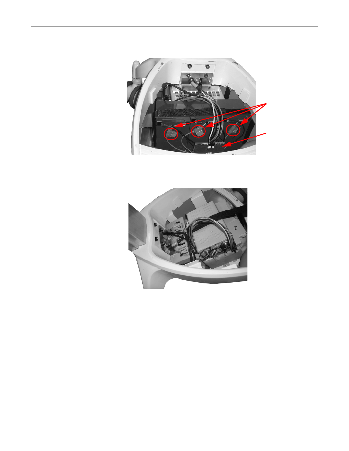
Connectors
1. Ensure the AC cable is disconnected from the wall outlet and power
supply is in OFF (down) position.
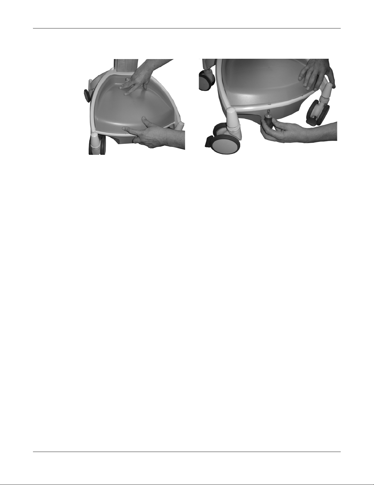
2. Loosen and remove mounting screws (2x) from bottom of base cover as
shown below.
a. Li-Nano Power Supply Batteries: Plug both connectors to the Li-
Nano batteries and check for accuracy.
Revision 1.0 Metro® AccessPoint™ Mobile Computing System Operator Manual 2-5
LO1-530
Getting Started: Getting Started with the Workstation
Connectors
Gas Gauge Board
b. SLA Power Supply Batteries: SLA batteries are always shipped
connected as shown below.
c. LiFe Power Supply Batteries: Plug the connectors to the LiFe
batteries and check for accuracy.
2-6 Metro® AccessPoint™ Mobile Computing System Operator Manual Revision 1.0
LO1-530
Getting Started: Getting Started with the Workstation
3. Install base cover and tighten the screws (2x) as shown below.
Charge Power Supply Battery
NOTE
The workstation’s electrical connections to the monitor, keyboard and
technology tray must be made per the AccessPoint Workstation Wiring
Diagram. Contact Metro Service for the most current wiring diagram.
Before placing an AccessPoint workstation into service for the first time
with the Li-Nano, SLA, LiFe power supply, the power supply battery should
be initially charged at least 8 hours. To charge the battery, plug the coiled
AC power cord into an AC outlet and put the ON/OFF switch into the “ON”
position which is located on the back of power supply as shown below.
Revision 1.0 Metro® AccessPoint™ Mobile Computing System Operator Manual 2-7
LO1-530

Getting Started: Getting Started with the Workstation
In the “ON” position, the power supply provides power to the AccessPoint
workstation. If the workstation is not being used for an extended period of
time, the ON/OFF switch should be put in the OFF position. The switch
position disconnects the battery from any internal or external equipment and
avoids deep discharges of the battery, which can cause damage to the
battery.
WARNING
Risk of Electric Shock - The power supply employs a
Lithium Iron Nano-Phosphate (Li-Nano) battery to provide
mobile DC output power. Low voltage (11-15V) DC power
is available from the power supply even when the AC cord
is disconnected from an AC outlet. To remove DC power,
put the ON/OFF Switch in the “OFF” position.
NOTE
After the initial charge, the charge time from a completely discharged
battery is typically 2 hours in fan mode and 3 hours in fan less mode
with LiFe and Li-Nano and 4 hours for SLA regardless of fan mode.
NOTE
If the Power Supply has been switched to “OFF” for more than 1 week,
connect the workstation to AC to wake up the power supply before.
2-8 Metro® AccessPoint™ Mobile Computing System Operator Manual Revision 1.0
LO1-530

Getting Started: Getting Started with the Workstation
Computer Power Tips and Cable Connections
Computer Power Tips
Tip No. Metro P/N Voltage Computers Tip No. Metro P/N Voltage Computers
MT2 C13-957 12V Praim XP9400-A, Thin Client MT41 C13-523 19V Acer Veriton Z2610, All in One
Praim I10, Thin Client AOPEN DE5100, Mini PC
IGEL UD3, Thin Client Lenovo M72 Tiny, Mini-PC
IGEL UD5, Thin Client Lenovo M92 Tiny, Mini-PC
IGEL H700C, Thin Client Nexlink Mini X11, Mini-PC
Motion Computing C5, Tablet Tangent Rugged Mini VI (Bar
106), Mini-PC
Wyse C90LE, C90LEW,
C90LEW7, Thin Client
MT2 C13-957 16V Panasonic H2, Tablet Tangent Rugged Mini N, Mini-
MT5 C13-632 19V HP t510, Thin Client Tangent Vita LT, All in One
HP t5565, Thin Client Tangent Vita 2000SA, All in
HP t5740, Thin Client Wyse D90D7, Thin Client
Seneca MP-57, Mini-PC Wyse R90L, R90LW, Thin
Tangent Medix T19B, All in One Wyse V90LE, V90LEW, Thin
Tangent Medix T19i, All in One Wyse Z90LE, Z90LEW,
Tangent Medix T22a, All in One Zotac ZBOX HD-ID40, Mini-
Tangent Medix T22i, All in One MT44 C13-482 19V All Lenovo Laptop computers
Tangent Rugged Mini UT,
Mini-PC
PC
One
Client
Client
Z90D7, Z90DW, Z90SW, Thin
Client
PC
Tangent Rugged Mini 965, Mini-PCMT55 C13-484 19V All HP Laptop computers
MT23 C13-483 19 V All Dell E Series laptop
computers
MT41 C13-532 12V Tangent Rugged Mini I, Mini-PC Panasonic CF-51, Laptop
Tangent Rugged Mini VA, MiniPC
VXL Itona F24, Thin Client
Revision 1.0 Metro® AccessPoint™ Mobile Computing System Operator Manual 2-9
MT41 C13-523 16V Panasonic H1, Tablet
Panasonic T7, Laptop
Panasonic CF-18, Laptop
Panasonic CF-19, Laptop
LO1-530

Getting Started: Getting Started with the Workstation
Tip Dimensions
Tip # Tip P/N Tip Size
MT #2 C13-957 ID 2.10 mm, OD 5.50 mm & 11.00 mm long
MT #5 C13-632 ID 1.60 mm, OD 4.80 mm & 11.00 mm long
MT #23 C13-483 ID 5.00 mm, OD 7.40 mm & 12.50 mm long
MT #41 C13-532 ID 2.50 mm, OD 5.50 mm & 12.50 mm long
MT #44 C13-482 ID 5.45 mm, OD 7.90 mm & 11.50 mm long
MT #55 C13-484 ID 5.00 mm, OD 7.40 mm & 12.50 mm long
Computer Power Cables
Metro P/N Voltages Computer
C13-781 19V HP 7800, 7900, 8000, 8200, 8300 USDT Computer
HP t610, Thin Client
HP 6000, 6300, 8200, 8300 ELITE, All in One
402049 12V Tangent Medix 1500, 1700SF, 1900SF, All in One
402384 19V Tangent Rugged Mini GM, Mini-PC
402743 19V Tangent Rugged Mini VI (Bar 105), Mini-PC
Tangent Vita 2150, All in One
AC Dell Optiplex 780/790/7010/9010, USFF
Dell FX-160, Thin Client
HP 6300/8300 Elite, All in One
Lenovo A70Z, M71Z, M72Z, All in One
2-10 Metro® AccessPoint™ Mobile Computing System Operator Manual Revision 1.0
LO1-530
Getting Started: Getting Started with the Workstation
Configure Selectable Voltages
1. Request a link from Intermetro Customer Service to download
BatteryPro400.
2. Install BatteryPro400 on a laptop computer to change the voltage(s).
3. Connect the computer to via USB to the power supply.
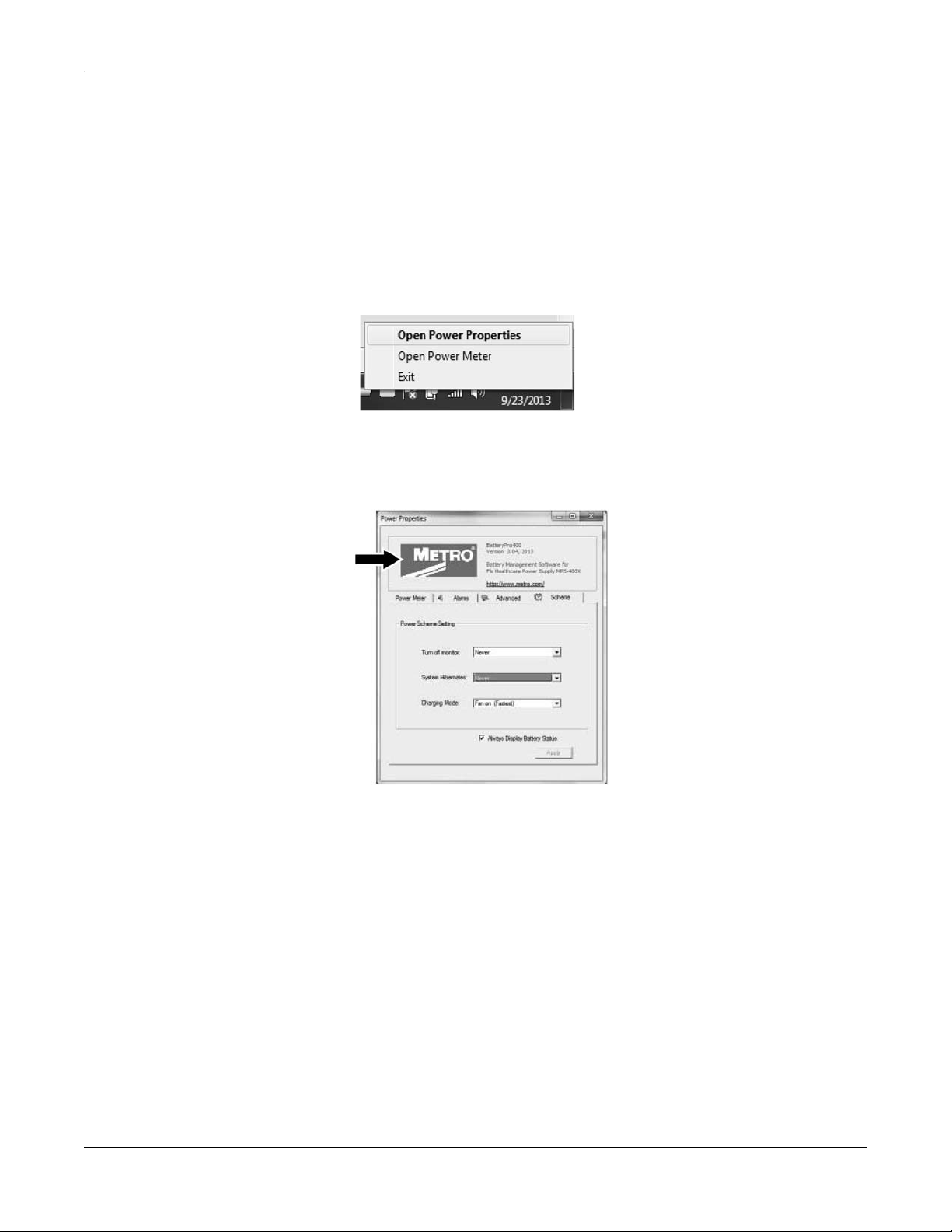
4. Start BatteryPro400 and right click on the BatteryPro400 icon (grey
battery icon).
5. Select “Open Power Properties”.
6. Hold down the CTRL key and click on the METRO label as shown
below. The Diagnosis tab opens.
7. In order to change the selectable voltage on Diagnosis tab:
Click on “DC1 Setting” for 12-24 V (DC1) or
Revision 1.0 Metro® AccessPoint™ Mobile Computing System Operator Manual 2-11
LO1-530
Getting Started: Getting Started with the Workstation
DC 1 Setting
DC 3 Setting
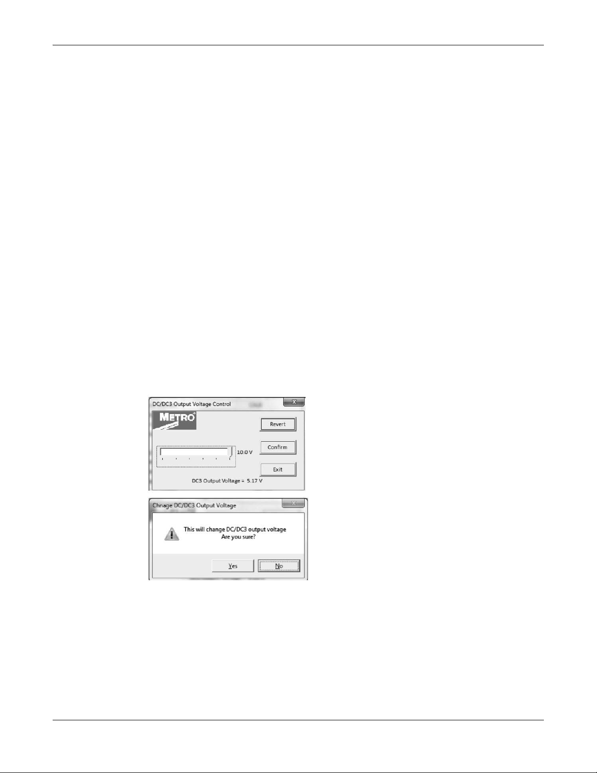
Click on “DC3 Setting” for 5-10 V (DC3).
8. With the slider select the desired voltage. After selecting the voltage
click “Confirm.”
9. To confirm the voltage change, click “YES” as shown.
2-12 Metro® AccessPoint™ Mobile Computing System Operator Manual Revision 1.0
LO1-530
 Loading...