

Page 1
WCM5100
Managed Ethernet Extender
V8.23
User Manual
DATE: 5th September 2013
DOCUMENT NO: 76-02-087
REVISION: D
PREPARED BY: Ian Banbrook
Metrodata Ltd
Fortune House, Crabtree Office Village
Eversley Way, Egham Surrey, TW20 8RY, UK
Tel +44 1 784 744700
Fax: +44 1 784 744730
E-Mail: [email protected]
Page 2

METRODATA LTD WCM5100
User Manual
METRODATA LTD
No part of this publication may be reproduced, transmitted,
transcribed, stored in a retrieval system, or translated into any
language or computer language, in any form or by any means,
electronic, mechanical, magnetic, optical, chemical, manual or
otherwise, without the prior written permission of
Metrodata Ltd, Fortune House,
Crabtree Office Village, Eversley Way,
2 of 123
Egham, Surrey, TW20 8RY, United Kingdom
.
DISCLAIMER
Metrodata Ltd makes no representations or warranties with respect
to the contents hereof and specifically disclaims any implied
warranties or merchantability or fitness for any particular purpose.
Further, Metrodata Ltd reserves the right to revise this publication
and to make changes from time to time in the content hereof without
obligation of Metrodata Ltd to notify any person of such revision or
changes.
Copyright 2013 by Metrodata Ltd,
All Rights Reserved
76-02-087 Rev D
Page 3

METRODATA LTD WCM5100
User Manual
Document Revision History
3 of 123
4th April 2011 XA Document Created
15th April 2011 XB Updated for Multiple VC modes
20th May 2011 A Document Released
29th June 2011 B Document typos corrected
New feature VC-3 allocation added
22nd August 2011 C Updated to add multiple VC-3 with VCAT and
LCAS support
5th September 2013 D Updated manual for 8.23 software
76-02-087 Rev D
Page 4

METRODATA LTD WCM5100
4 of 123
User Manual
TABLE OF CONTENTS
1 INTRODUCTION........................................................................................................10
1.1
WCM5100 Rear Panel ..................................................................................................................................... 11
1.2
Safety................................................................................................................................................................. 11
1.3
Electro Magnetic Compatibility......................................................................................................................12
1.3.1 EN55022 Statement....................................................................................................................................... 12
1.3.2 FCC Declaration............................................................................................................................................ 12
1.4
WEEE Directive ...............................................................................................................................................12
1.5
RoHS Compliance ............................................................................................................................................ 12
2 INSTALLATION .........................................................................................................13
2.1
WCM5100 Rear Panel .................................................................................................................................... 13
2.1.1 Mains Power.................................................................................................................................................. 13
2.1.2 DC Power ...................................................................................................................................................... 13
2.2
Base Label and Bit Switches............................................................................................................................ 14
2.2.1 WCM5100 Base Label .................................................................................................................................. 14
2.2.2 Bit Switches................................................................................................................................................... 14
2.2.2.1 Bit switch 1, Boot Mode 0 ................................................................................................................... 14
2.2.2.2 Bit switch 2, Boot Mode 1 ................................................................................................................... 15
2.2.2.3 Bit switch 3, DHCP.............................................................................................................................. 15
2.2.2.4 Bit switch 4, Framing........................................................................................................................... 15
2.2.2.5 Bit switch 5, Timing Mode .................................................................................................................. 15
2.2.2.6 Bit switch 6,Unused ............................................................................................................................. 16
2.2.2.7 Bit switch 7, SFP Mode .......................................................................................................................16
2.2.2.8 Bit switch 8, Factory Default ............................................................................................................... 16
2.3
Rackmounting................................................................................................................................................... 16
3 WCM APPLICATIONS...............................................................................................18
3.1
WCM Normal Mode ........................................................................................................................................18
3.2
WCM VLAN Trunk Mode .............................................................................................................................. 18
3.3
VLAN Mode...................................................................................................................................................... 19
3.4
S-Tag Mode.......................................................................................................................................................19
4 QUICK START CONFIGURATION............................................................................20
4.1
Cold Start the Unit ...........................................................................................................................................20
4.2
Access the WCM............................................................................................................................................... 20
4.3
Logging onto WCM5100..................................................................................................................................21
4.3.1 User Interface Navigation.............................................................................................................................. 21
76-02-087 Rev D
Page 5

METRODATA LTD WCM5100
5 of 123
User Manual
4.4
Configure the WAN interface..........................................................................................................................23
4.4.1 WCM5100 WAN Configuration ...................................................................................................................23
4.5
Set IP Address................................................................................................................................................... 24
4.6
Set Default Route..............................................................................................................................................25
4.7
Save the Configuration.....................................................................................................................................26
5 ADVANCED CONFIGURATION................................................................................27
5.1
System Configuration....................................................................................................................................... 27
5.1.1 Setting the Time and Date .............................................................................................................................28
5.1.2 Setting the Node Name..................................................................................................................................29
5.1.3 Access Control............................................................................................................................................... 30
5.1.3.1 Password ..............................................................................................................................................30
5.1.3.1.1 Password Recovery ......................................................................................................................... 31
5.1.3.2 ‘View’ User.......................................................................................................................................... 31
5.1.3.3 Super Me.............................................................................................................................................. 31
5.1.3.4 TACACS+............................................................................................................................................31
5.1.3.4.1 Authentication.................................................................................................................................32
5.1.3.4.2 Timeout ........................................................................................................................................... 32
5.1.3.4.3 Retries ............................................................................................................................................. 32
5.1.3.4.4 Server .............................................................................................................................................. 32
5.1.3.4.5 Encryption Key ............................................................................................................................... 32
5.1.4 Welcome Screen............................................................................................................................................ 33
5.1.5 Software Version ........................................................................................................................................... 35
5.1.6 Output Config................................................................................................................................................ 36
5.1.7 Input Config................................................................................................................................................... 36
5.1.8 Warm Start..................................................................................................................................................... 36
5.1.9 Cold Start....................................................................................................................................................... 37
5.1.10
Event Logs................................................................................................................................................ 37
5.1.10.1 System Event Log ................................................................................................................................ 38
5.1.10.2 Alarm Event Log.................................................................................................................................. 38
5.1.10.3 Config Event Log................................................................................................................................. 39
5.2
Operational Modes........................................................................................................................................... 40
5.2.1 VLAN Mode..................................................................................................................................................40
5.2.2 Flow Control..................................................................................................................................................40
5.2.3 Max Frame Size.............................................................................................................................................41
5.2.4 Priority Translation........................................................................................................................................41
5.2.5 RSTP.............................................................................................................................................................. 42
5.2.5.1 Mode ....................................................................................................................................................42
5.2.5.2 Priority ................................................................................................................................................. 42
5.2.5.3 Max Age............................................................................................................................................... 42
5.2.5.4 Hello Time ...........................................................................................................................................43
5.2.5.5 Forward Delay......................................................................................................................................43
5.2.5.6 Tx Hold................................................................................................................................................ 43
5.2.5.7 Version................................................................................................................................................. 43
5.2.5.8 Status....................................................................................................................................................44
5.2.5.8.1 Port Role..........................................................................................................................................44
5.2.5.8.2 Port State......................................................................................................................................... 44
5.3
Port Set Up Menu............................................................................................................................................. 45
5.3.1 LAN Port ....................................................................................................................................................... 46
5.3.1.1 State...................................................................................................................................................... 46
5.3.1.2 Link Status ...........................................................................................................................................46
5.3.1.3 Auto Negotiation.................................................................................................................................. 47
76-02-087 Rev D
Page 6

METRODATA LTD WCM5100
6 of 123
User Manual
(Max).............................................................................................................................................................47
5.3.1.4 Speed....................................................................................................................................................47
5.3.1.5 (Max) Duplex.......................................................................................................................................47
5.3.1.6 Negotiated............................................................................................................................................ 47
5.3.1.7 MDI/MDIX.......................................................................................................................................... 48
5.3.1.8 Tagging and Priority ............................................................................................................................48
5.3.1.8.1 C-VLAN Mode ............................................................................................................................... 48
5.3.1.8.1.1 VLAN Allocation..................................................................................................................... 48
5.3.1.8.1.2 Untagged..................................................................................................................................49
5.3.1.8.1.3 Default VLAN .........................................................................................................................49
5.3.1.8.1.4 Priority Source ......................................................................................................................... 49
5.3.1.8.1.5 Default Priority ........................................................................................................................ 50
5.3.1.8.1.6 Control C-VLAN ..................................................................................................................... 50
5.3.1.8.2 QinQ/S-VLAN Mode...................................................................................................................... 50
5.3.1.8.2.1 Port Mode................................................................................................................................. 51
5.3.1.8.2.2 S-VLAN (Access Port) ............................................................................................................ 51
5.3.1.8.2.3 Priority Source (Access Port)................................................................................................... 51
5.3.1.8.2.4 Default Priority (Access Port)..................................................................................................52
5.3.1.8.2.5 S-VLAN Allocation (Trunk Port )...........................................................................................52
5.3.1.8.2.6 EtherType (Trunk Port)............................................................................................................ 52
5.3.1.8.2.7 Control S-VLAN...................................................................................................................... 52
5.3.1.9 OAM ....................................................................................................................................................53
5.3.1.9.1 OAM Mode ..................................................................................................................................... 54
5.3.1.9.2 OAM Status..................................................................................................................................... 54
5.3.1.9.3 OAM Counters ................................................................................................................................55
5.3.1.9.4 OAM Events....................................................................................................................................55
5.3.1.10 RSTP.................................................................................................................................................... 56
5.3.1.10.1 RSTP Port Priority......................................................................................................................... 56
5.3.1.10.2 RSTP Port Cost.............................................................................................................................. 56
5.3.1.10.3 RSTP Port Fast ..............................................................................................................................56
5.3.1.11 Link Loss Forwarding.......................................................................................................................... 57
5.3.1.12 Counters............................................................................................................................................... 57
5.3.2 SFP Port......................................................................................................................................................... 58
5.3.2.1 SFP Type.............................................................................................................................................. 58
5.3.2.2 State...................................................................................................................................................... 58
5.3.2.3 Link State............................................................................................................................................. 59
5.3.2.4 (Max) Speed.........................................................................................................................................59
5.3.2.5 Auto Negotiation.................................................................................................................................. 59
5.3.2.6 Negotiated............................................................................................................................................ 59
5.3.2.7 SFP Management ................................................................................................................................. 60
5.3.2.7.1 Device Details ................................................................................................................................. 60
5.3.2.7.2 Notifications.................................................................................................................................... 61
5.3.2.8 Tagging and Priority ............................................................................................................................62
5.3.2.9 OAM ....................................................................................................................................................62
5.3.2.10 RSTP.................................................................................................................................................... 62
5.3.2.10.1 RSTP Port Priority......................................................................................................................... 62
5.3.2.10.2 RSTP Port Cost.............................................................................................................................. 63
5.3.2.10.3 RSTP Port Fast ..............................................................................................................................63
5.3.2.11 Link Loss Forwarding.......................................................................................................................... 63
5.3.2.12 Counters............................................................................................................................................... 63
5.3.3 VCG...............................................................................................................................................................64
5.3.3.1 State...................................................................................................................................................... 64
5.3.3.2 Encapsulation.......................................................................................................................................64
5.3.3.2.1.1 GFP FCS.................................................................................................................................. 65
5.3.3.2.1.2 Strip MAC FCS........................................................................................................................ 65
5.3.3.2.1.3 Payload Scrambler ................................................................................................................... 65
5.3.3.2.2 Priority Table................................................................................................................................... 66
5.3.3.2.2.1 802.1p Mode ............................................................................................................................ 66
5.3.3.2.2.2 IP DSCP Mode......................................................................................................................... 66
76-02-087 Rev D
Page 7

METRODATA LTD WCM5100
User Manual
7 of 123
5.3.3.3 LCAS/VCAT ....................................................................................................................................... 67
5.3.3.4 LCAS Status......................................................................................................................................... 67
5.3.3.5 Tagging and Priority ............................................................................................................................68
5.3.3.6 OAM ....................................................................................................................................................68
5.3.3.7 RSTP.................................................................................................................................................... 69
5.3.3.7.1 RSTP Port Priority........................................................................................................................... 69
5.3.3.7.2 RSTP Port Cost ............................................................................................................................... 69
5.3.3.7.3 RSTP Port Fast................................................................................................................................ 69
5.3.3.8 Link Loss Forwarding.......................................................................................................................... 70
5.3.3.9 Counters............................................................................................................................................... 70
5.3.4 WAN Ports .................................................................................................................................................... 71
5.3.4.1 State...................................................................................................................................................... 71
5.3.4.2 SFP Type.............................................................................................................................................. 71
5.3.4.3 SFP Management ................................................................................................................................. 72
5.3.4.3.1 Device Details ................................................................................................................................. 72
5.3.4.3.2 Notifications.................................................................................................................................... 73
5.3.4.4 Active Port ...........................................................................................................................................73
5.3.4.5 Fallback Timeout .................................................................................................................................74
5.3.4.6 Timing..................................................................................................................................................74
5.3.4.7 Framing................................................................................................................................................ 74
5.3.4.8 Overhead.............................................................................................................................................. 75
5.3.4.8.1 C1/J0 Selection................................................................................................................................75
5.3.4.8.2 J0 Transmit...................................................................................................................................... 75
5.3.4.8.3 J0 Expected ..................................................................................................................................... 75
5.3.4.8.4 Receiving.........................................................................................................................................76
5.3.4.8.5 E1 Value.......................................................................................................................................... 76
5.3.4.9 Payload................................................................................................................................................. 76
5.3.4.10 Unused Tributaries Send...................................................................................................................... 76
5.3.5 VC-4 Configuration....................................................................................................................................... 77
5.3.5.1 State...................................................................................................................................................... 77
5.3.5.2 Path Signal Label ................................................................................................................................. 77
5.3.5.3 Receiveing............................................................................................................................................ 77
5.3.5.4 J1 Transmit........................................................................................................................................... 78
5.3.5.5 J1 Expected .......................................................................................................................................... 78
5.3.5.6 Receiving ............................................................................................................................................. 78
5.3.5.7 RDI Type ............................................................................................................................................. 78
5.3.5.8 VCG..................................................................................................................................................... 78
5.3.6 VC-3.............................................................................................................................................................. 79
5.3.6.1 State...................................................................................................................................................... 79
5.3.6.2 Path Signal Label ................................................................................................................................. 79
5.3.6.3 Receiveing............................................................................................................................................ 79
5.3.6.4 J1 Transmit........................................................................................................................................... 80
5.3.6.5 J1 Expected .......................................................................................................................................... 80
5.3.6.6 Receiving ............................................................................................................................................. 80
5.3.6.7 RDI Type ............................................................................................................................................. 80
5.3.6.8 VCG..................................................................................................................................................... 80
5.4
V.24 Setup ......................................................................................................................................................... 81
5.4.1 Usage.............................................................................................................................................................81
5.4.2 Console Set Up.............................................................................................................................................. 82
5.4.2.1 Terminal Type...................................................................................................................................... 82
5.4.2.2 via Modem ...........................................................................................................................................83
5.4.2.3 Baud Rate.............................................................................................................................................83
5.4.2.4 Parity.................................................................................................................................................... 83
5.4.2.5 Data Bits............................................................................................................................................... 84
5.4.2.6 Stop Bits...............................................................................................................................................84
5.4.2.7 Load New Config................................................................................................................................. 84
5.5
Management Entity..........................................................................................................................................85
76-02-087 Rev D
Page 8

METRODATA LTD WCM5100
User Manual
8 of 123
5.5.1 Proxying ........................................................................................................................................................85
5.5.1.1 Server Mode Proxy ..............................................................................................................................86
5.5.1.1.1 Proxying .......................................................................................................................................... 86
5.5.1.1.2 Host Interface..................................................................................................................................86
5.5.1.1.3 DHCP.............................................................................................................................................. 86
5.5.1.1.4 IP Address ....................................................................................................................................... 87
5.5.1.1.5 Network Mask................................................................................................................................. 87
5.5.1.2 Client Mode Proxy...............................................................................................................................87
5.5.1.2.1 Interface...........................................................................................................................................87
5.5.2 Interface......................................................................................................................................................... 88
5.5.2.1 State...................................................................................................................................................... 88
5.5.2.2 Physical Address..................................................................................................................................88
5.5.2.3 DHCP................................................................................................................................................... 89
5.5.2.4 IP Address............................................................................................................................................ 89
5.5.2.5 Network Mask...................................................................................................................................... 89
5.5.2.6 AT Table .............................................................................................................................................. 89
5.5.2.7 Statistics............................................................................................................................................... 90
5.5.2.8 c-VLAN ............................................................................................................................................... 90
5.5.2.9 QinQ/S-VLAN.....................................................................................................................................90
5.5.2.10 802.1p Priority ..................................................................................................................................... 90
5.5.2.11 Override Incoming ............................................................................................................................... 91
5.5.3 IP ................................................................................................................................................................... 91
5.5.3.1 Default TTL .........................................................................................................................................91
5.5.3.2 DSCP Priority ...................................................................................................................................... 91
5.5.3.3 Routing Table....................................................................................................................................... 92
5.5.3.3.1 Add a new Route............................................................................................................................. 92
5.5.3.3.2 Delete a Route .................................................................................................................................93
5.5.3.4 Forwarding........................................................................................................................................... 93
5.5.3.5 Statistics............................................................................................................................................... 93
5.5.4 UDP...............................................................................................................................................................95
5.5.4.1 Statistics............................................................................................................................................... 95
5.5.5 TCP................................................................................................................................................................ 95
5.5.5.1 Statistics............................................................................................................................................... 96
5.5.5.2 Connection Table ................................................................................................................................. 96
5.5.6 SNMP Management ...................................................................................................................................... 97
5.5.6.1 Read/Write/Trap Community............................................................................................................... 97
5.5.6.2 Contact Person .....................................................................................................................................97
5.5.6.3 Node Name .......................................................................................................................................... 98
5.5.6.4 Location ............................................................................................................................................... 98
5.5.6.5 Managers..............................................................................................................................................98
5.5.6.6 Statistics............................................................................................................................................... 99
5.5.6.7 Trap Alarms .......................................................................................................................................100
5.5.6.7.1 LAN Port Trap Definitions............................................................................................................100
5.5.6.7.2 SFP Port Trap Defintions ..............................................................................................................101
5.5.6.7.3 VCG Port Trap Defintions ............................................................................................................ 103
5.5.6.7.4 WAN Port Trap Defintions ........................................................................................................... 103
5.5.6.7.5 VC-4 Traps.................................................................................................................................... 104
5.5.6.7.6 VC-3 Traps.................................................................................................................................... 105
5.5.7 Telnet / SSH ................................................................................................................................................107
5.5.7.1 Access Method...................................................................................................................................107
5.5.7.2 Timeout.............................................................................................................................................. 107
5.5.8 TFTP............................................................................................................................................................108
5.5.8.1 TFTP Configuration........................................................................................................................... 108
5.5.8.1.1 Client Mode................................................................................................................................... 108
5.5.8.1.1.1 Remote IP............................................................................................................................... 108
5.5.8.1.1.2 Get New Software..................................................................................................................108
5.5.8.1.1.3 Boot S/W Upgrade.................................................................................................................109
5.5.8.1.1.4 Get Confuration File ..............................................................................................................110
5.5.8.1.1.5 Put Configuration File............................................................................................................ 110
76-02-087 Rev D
Page 9

METRODATA LTD WCM5100
User Manual
9 of 123
5.5.8.1.1.6 put Report............................................................................................................................... 111
5.5.8.1.2 Server Mode..................................................................................................................................111
5.5.9 Ping..............................................................................................................................................................112
5.6
Saving the Configuration...............................................................................................................................113
5.7
Global Status...................................................................................................................................................114
5.7.1 Interface....................................................................................................................................................... 114
5.7.2 State.............................................................................................................................................................114
5.7.3 Test.............................................................................................................................................................. 115
5.7.4 Alarms ......................................................................................................................................................... 115
5.7.4.1 LAN Port Alarms............................................................................................................................... 116
5.7.4.2 SFP Port Alarms................................................................................................................................. 116
5.7.4.3 VCG Alarms ...................................................................................................................................... 117
5.7.4.4 WAN Ports.........................................................................................................................................118
5.7.4.4.1 VC-4..............................................................................................................................................118
5.7.4.4.2 VC-3 Alarms ................................................................................................................................. 119
5.7.5 Mode, Speed, Duplex .................................................................................................................................. 119
5.7.6 VLAN Allocation ........................................................................................................................................119
5.8
ALARM EXTENSION .................................................................................................................................. 120
5.8.1 Clear Alarm Outputs.................................................................................................................................... 120
5.8.2 Alarm Actions..............................................................................................................................................121
5.9
Performance Data...........................................................................................................................................122
5.9.1 Interface....................................................................................................................................................... 122
5.9.2 Display Mode .............................................................................................................................................. 122
5.9.3 Summary Style ............................................................................................................................................ 123
5.9.4 Physical Layer Stats.....................................................................................................................................123
76-02-087 Rev D
Page 10
METRODATA LTD WCM5100
10 of 123
User Manual
1 INTRODUCTION
The Metrodata WCM5100 allows for the extension of an Ethernet Service over an SDH,
Wide Area Network Connection. The WCM5100 is a managed unit allowing for the
effective demarcation between LAN and WAN services. Management of the WCM5100 is
achieved using either Telnet/SSH or SNMP (V1/V2c) via either the LAN or WAN ports.
In cases where management is not required, or undesired, the WCM5100 can operate
standalone with simple configuration options provided using bit switches located on the
underside of the unit.
The Metrodata WCM5100 is a manageable multiport Ethernet Switch with an SDH uplink,
supporting automatic fallback when using dual SFP modules. The WCM5100 provides two
10/100/1000BaseT Auto Negotiating, Auto switching Ports as well as a single SFP port
supporting either 1000Base-X or 100Base-FX SFP modules. The WCM5100 operates as a
layer 2 bridge and as such may be used to extend a LAN segment over an SDH WAN link.
The WCM5100 has an internal LAN switch offering full wire-speed switching between
ports. The WCM5100 uses MAC address filtering to filter all local traffic and only forward
traffic destined for remote stations. Each of the WCM5100’s LAN ports support automatic
cross-over switching and will therefore connect directly to a Hub/Switch/Router or PC End
Station.
The WCM5100 has support for both tagged and untagged frames, with both VLAN C-Tag,
and Provider Bridge S-Tag (QinQ) modes supported.
The WCM5100 supports either IP DSCP, or IEEE802.1p based traffic prioritisation with
outgoing traffic being queued in one of four priority queues.
The WCM5100 supports link OAM, IEEE802.3ah and RSTP for loop prevention.
The WCM5100 performs GFP frame encapsulation and supports the VC-4 and VC-3 EoS (
Ethernet over Sonet ) modes. Internal packet buffers enable the WCM5100 to smooth out
bursty traffic and prevent packet loss as the higher layer protocols rate adapt to the SDH
capacity.
76-02-087 Rev D
Page 11
METRODATA LTD WCM5100
11 of 123
User Manual
1.1 WCM5100 Rear Panel
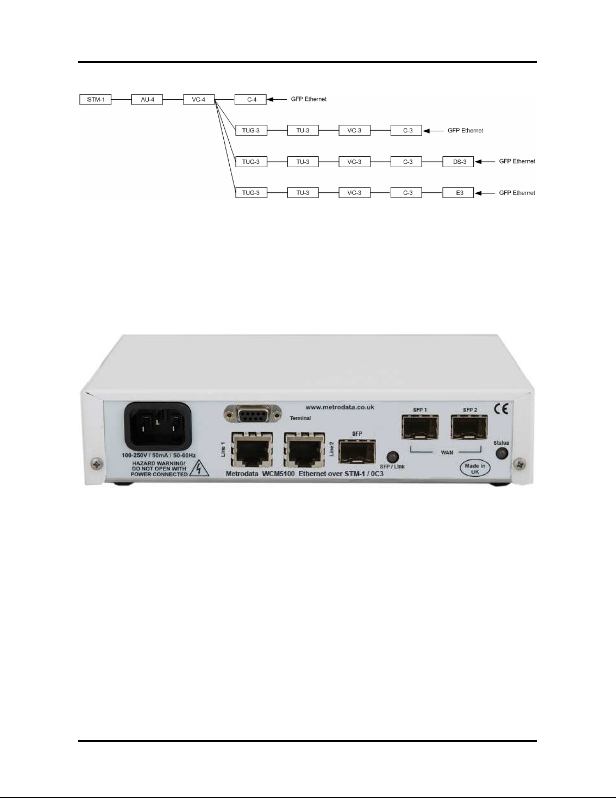
The WCM5100 device is a compact unit, as shown below, occupying half a shelf in a
traditional 19inch rack. All power and data connectors and LED status indicators are
accessible from the rear of the unit.
1.2 Safety
The WCM5100 must not be connected to cabling which would be required by BS6701 to
equipped with over voltage protection. The following ports on the WCM5100 are
designated SELV ( Safety Extra Low Voltage ) within the scope of EN41003
Terminal Port 9 Way D-Type
LAN Port(s) RJ45 10/100/1000BaseT
SFP
These ports must only be connected to SELV ports on other equipment in accordance with
EN60950 clause 2.3
76-02-087 Rev D
Page 12

METRODATA LTD WCM5100
12 of 123
User Manual
1.3 Electro Magnetic Compatibility
In order to ensure EMC compliance, all signal and data cables must be shielded and use
screened connector shells. The cable screens must be terminated to the screened
connector shell and not connected to any pins of the connector. Failure to use the correct
connectors may compromise EMC compliance.
1.3.1 EN55022 Statement
The WCM5100 is a Class A product. In a domestic environment, this product may cause
radio interference, in which case the user will be required to take adequate measures.
1.3.2 FCC Declaration
This equipment has been tested and found to comply with the limits of the Class A digital
device, pursuant to Part 15 of the FCC rules. These limits are designed to provide
reasonable protection against harmful interference when the equipment is operated in a
commercial environment. This equipment generates, uses and can radiate radio frequency
energy and, if not installed and used in accordance with the Installation and Operation
manual, may cause harmful interference to the radio communications. Operation of this
equipment in a residential area is likely to cause harmful interference in which case the
user will be required to correct the interference at his own expense.
1.4 WEEE Directive
The WCM5100 is covered by Directive 2002/96/EC ( OJ:L37/24/2003 ) on Waste Electrical
and Electronic Equipment ( WEEE ) Units must therefore not be disposed of in standard
landfill.
1.5 RoHS Compliance
The WCM5100 is compliant with the EU RoHS Directive 2002/95/EC. The RoHS directive
bans the use of six hazardous materials in products placed on the market after July 1st
2006. The six banned materials are Lead, Mercury, Hexavalent Chromium,
Polybrominated Biphenys, Polybrominated Diphenyl Ethers and Cadmium.
The WCM5100 is manufactured using a lead free soldering process and as such is fully
RoHS 6/6 compliant.
76-02-087 Rev D
Page 13
METRODATA LTD WCM5100
User Manual
2 INSTALLATION
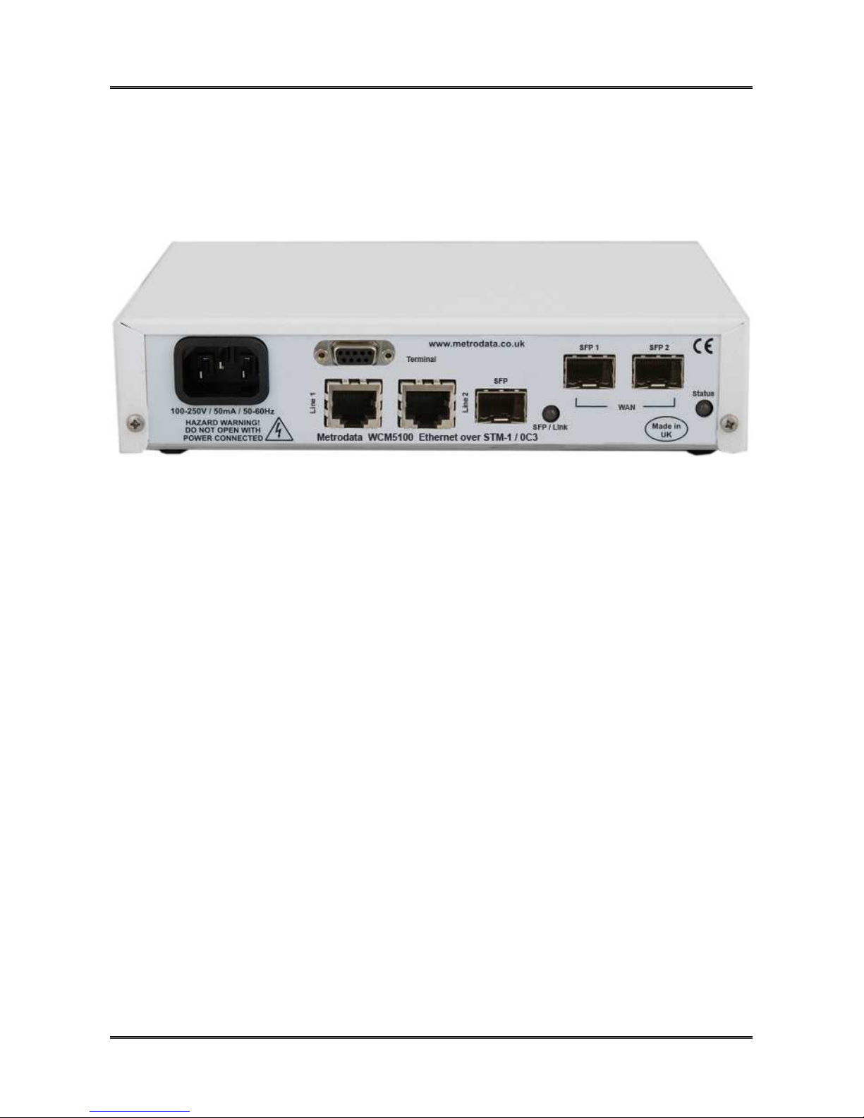
2.1 WCM5100 Rear Panel
13 of 123
The WCM5100 is available with either AC Mains or DC power options.
2.1.1 Mains Power
The WCM5100 has an internal power supply and is supplied via an IEC mains power
socket. The WCM5100 operates over the wide range 100 to 250V AC and draws less
than 6 watts.
2.1.2 DC Power
The WCM5100 is available with an internal DC power supply with two variants available,
DC -48V ( 36 to 72V DC )
DC 24V ( 7 to 36V DC )
DC powered units have an external earth stud which must be securely connected to an
earth connection to ensure EMC compliance.
76-02-087 Rev D
Page 14
METRODATA LTD WCM5100
14 of 123
User Manual
2.2 Base Label and Bit Switches
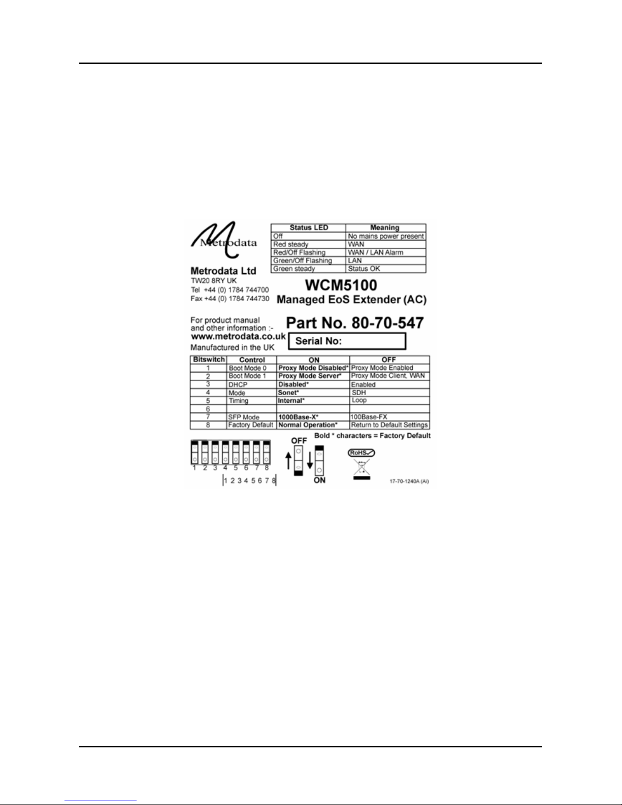
On the underside of the WCM5100 unit there are bit switches which may be used to
configure certain functions within the unit. The bit switches are used to configure the
default settings following a cold start.
2.2.1 WCM5100 Base Label
2.2.2 Bit Switches
The bit switches are used to configure the default settings following a cold start, either
from the console, or by powering on with switch 8 in the OFF position.
2.2.2.1 Bit switch 1, Boot Mode 0
This bit switch is used to determine whether the IP proxy management mode is enabled or
not. IP proxy mode utilises OAM to remotely manage a WCM5100 device.
ON Proxy Mode Disabled
OFF Proxy Mode Enabled,
76-02-087 Rev D
Page 15

METRODATA LTD WCM5100
15 of 123
User Manual
2.2.2.2 Bit switch 2, Boot Mode 1
This bit switch is ignored if Proxy Mode is disabled. When Proxy mode is enabled, this
switch setting determines whether the unit acts as Master/Server, or Slave/Client.
ON Proxy Mode, Server
OFF Proxy Mode, Client
2.2.2.3 Bit switch 3, DHCP
This bit switch enables DHCP for IP address allocation.
ON DHCP Disabled
OFF DHCP Enabled
2.2.2.4 Bit switch 4, Framing
This bit switch determines the operating mode of the SDH WAN interface.
ON SONET OC-3
OFF SDH STM-1
This bit switch is currently unused on the WCM5100 which does not offer SONET
operation.
2.2.2.5 Bit switch 5, Timing Mode
This bit switch determines the timing source for the SDH WAN interface
ON Internal Timing
OFF Loop Timing
Note, it is vital that one end of SDH WAN link is set to internal, as loop/loop will give an
unstable system.
76-02-087 Rev D
Page 16

METRODATA LTD WCM5100
16 of 123
User Manual
2.2.2.6 Bit switch 6,Unused
This bit switch is unused on the WCM5100,
2.2.2.7 Bit switch 7, SFP Mode
This bit switch is used to force the configuration of the SFP interface to match the SFP
type inserted.
ON 1000Base-X SFP
OFF 100Base-FX SFP
2.2.2.8 Bit switch 8, Factory Default
This bit switch will clear the stored configuration and return the unit to the default settings
as defined by the bit switches.
ON Normal Operation
OFF Factory Cold Start, load default settings
The main use of this switch it to ensure a unit can be accessed in the event that the
password has been lost.
2.3 Rackmounting
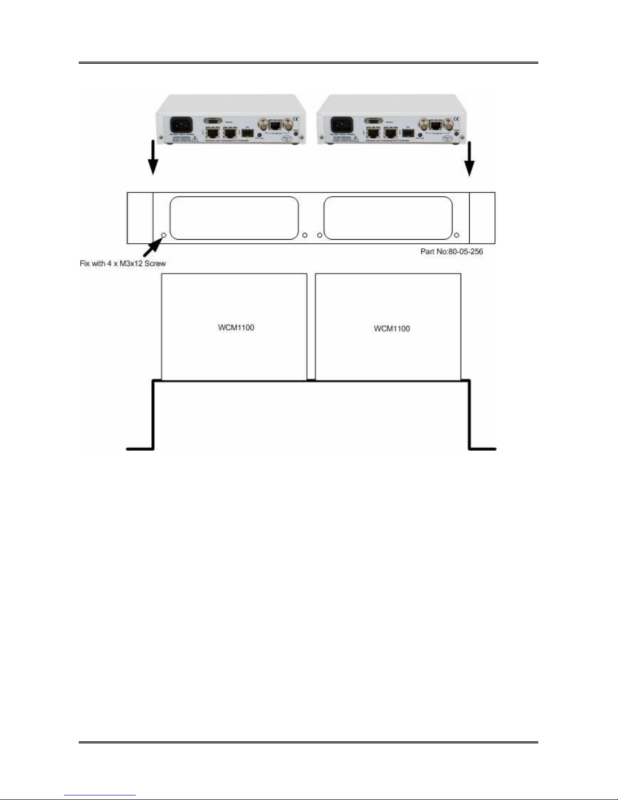
The WCM5100 is a standalone, desktop unit however it may be mounted in a standard 19
inch rack using the rack mounting kit, part number 80-05-256.
76-02-087 Rev D
Page 17
METRODATA LTD WCM5100
User Manual
17 of 123
To mount the WCM5100 in the 19 inch rack mount adaptor first remove the two M3x12
screws and washers from the rear panel of the unit. Then align the WCM5100 rear panel
with the mounting bracket, and secure the unit to the adaptor using the previously
removed screws.
When rack mounting, please ensure that the bit switches on the underside are correctly
configured prior to mounting the units in the rack.
76-02-087 Rev D
Page 18
METRODATA LTD WCM5100
18 of 123
User Manual
3 WCM APPLICATIONS
3.1 WCM Normal Mode
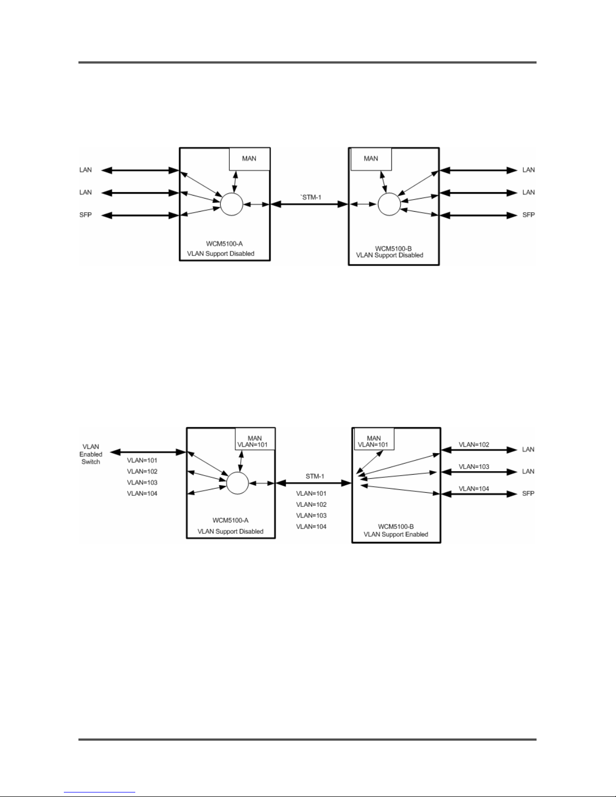
In this application, the WCM5100 is operating with Traffic Isolation Disabled. In this mode,
the WCM5100 acts as a simple, layer 2, 5 port switch with packetsswitched based on MAC
address alone. The WCM5100 supports both local and remote switching, and forwarding
over the WAN trunk.
Management traffic is not isolated from the through data traffic, and both units may be
managed from any port.
3.2 WCM VLAN Trunk Mode
In this application, WCM-A is connected to a VLAN enabled LAN switch. The LAN switch
is configured as a VLAN trunk and all packets are tagged with VLAN Tags. WCM-A is
operating with VLAN support enabled but all ports defined as Trunks. A VLAN ID is
allocated to the Manager and thus management traffic is isolated from the user traffic and
the management VLAN, in this case 101, can be used to manage the WCM’s. WCM1100B is configured with VLAN support enabled but each port is configured as an access port
and isolated to a single VLAN.
Trunk ports expect packets to be tagged, whilst access ports expect untagged packets and
will add tag and priority to incoming packets.
76-02-087 Rev D
Page 19
METRODATA LTD WCM5100
19 of 123
User Manual
3.3 VLAN Mode
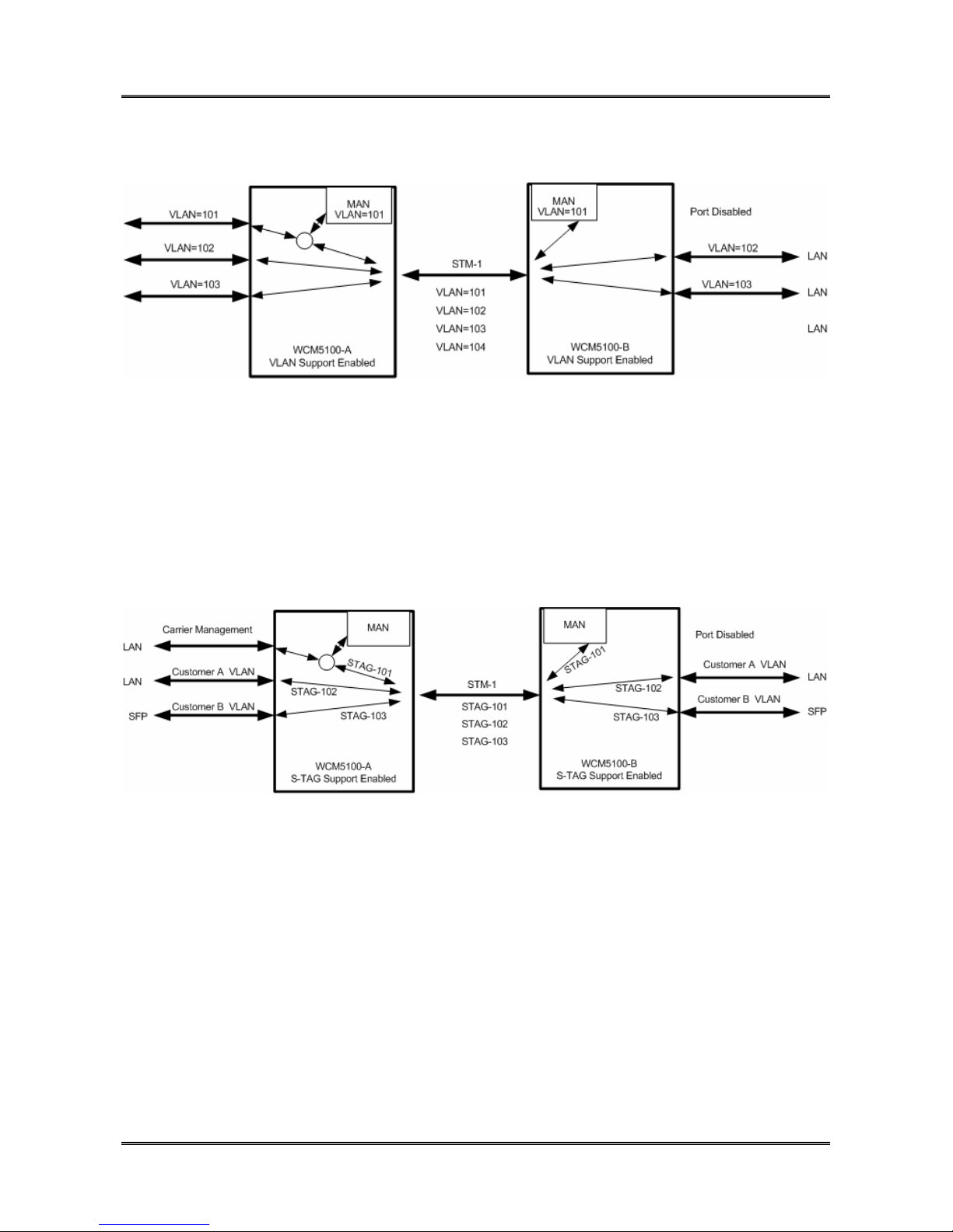
In this mode, both WCM units have VLAN support enabled, and all ports are defined as
access ports VLAN 101 is used as the management VLAN and in unit WCM-A the VLAN
group 101 includes the LAN Port 1, the Manager and the SDH WAN port. At the remote
end, The SFP port is disabled to prevent customer access to the WCM manager.
3.4 S-Tag Mode
In this mode, the WCM adds a, port based, S-TAG to all incoming traffic. Where customer
traffic is already VLAN tagged, this leads to double tagging or ‘QinQ’ operation. The use
of the S-TAG enables the carrier to isolate customer traffic. Carrier management traffic is
carried with a separate S-Tag giving management access to both units, and on the
customer site the external management access is disabled.
76-02-087 Rev D
Page 20

METRODATA LTD WCM5100
20 of 123
User Manual
4 QUICK START CONFIGURATION
The following guide gives a simple, quick start introduction to configuring the WCM5100
for Normal Mode operation as shown in section 2.1
4.1 Cold Start the Unit
When a WCM5100 is shipped from the factory it will be in the default condition, however
with previously used equipment this may not be the case. To return the unit to the default
state will require a power cycle and configuration of the bit switches.
The underside of the unit has a set of accessible bit switches and a label, as shown below
for the two products:
Ensure all other bit switches are in the desired default positions.
To cold start the unit, first set bit switch 8 (Cold Start) to the OFF (Return to Default
Settings) position. Power up the WCM5100, wait for the Status LED to come on in any
state, and then power down. To return to normal mode, return bit switch 8 to the ON
(Normal Operation) position.
4.2 Access the WCM
Initial access to the WCM5100 is made using the Terminal Port on the rear panel of the
unit. The Terminal port defaults to 19200baud, 8bit, No Parity, 1 Stop Bit. The 9 Way DType is configured as a DCE port with standard pin out as shown below:
Pin Direction
Signal
1 out DCD
2 out RXD*
3 In TXD*
4 In DTR
5 Signal Ground*
6 out DSR
7 In RTS
8 out CTS
Figure 3.3 Terminal Port Connector Pin Configuration
76-02-087 Rev D
9 no connect
Page 21

METRODATA LTD WCM5100
21 of 123
User Manual
4.3 Logging onto WCM5100
The initial access to the WCM must use a terminal connected to the terminal port.
The WCM has a password protected, menu driven user interface. When a management
session is connected to the WCM, the welcome banner will be displayed as shown:
Metrodata WCM5100: Local connection to “”
Password (‘view’ to view only ) :
At the prompt, enter the password to gain access to the WCM. The default password is
the product name, ie “wcm5100” For security, the password is obscured with an asterisk
(*) being displayed for each character typed. An incorrect password will lead to the
welcome banner being redisplayed. A correct password will lead onto the main set up
menu as shown below:
Metrodata WCM5100 "" Alarms: Major
MAIN SET-UP
Global status <display>
alarm eXtension <menu>
Operational Modes <menu>
Port set-up <menu>
V.24 set-up <menu>
Management Entity <menu>
System <menu>
Update EEPROM
circuit/flow Tests <menu>
performance Data <menu>
First CAPITAL - select item
<escape> - exit menu
4.3.1 User Interface Navigation
The WCM user interface is a simple, menu based interface. Each selectable item may be
selected by typing the first capital of the option, e.g. for “Port set-up” type <P>1 or <p>.
Sometimes, where multiple items have the same starting letter the selection capital will not
be the first letter, e.g. “alarm eXtension” which is selected with <X> or <x>.
1
Encapsulating an item within < > indicates a key press is required, for example <P>
means type P.
76-02-087 Rev D
Page 22

METRODATA LTD WCM5100
22 of 123
User Manual
On the right side of the display is a list of what is below each item. This could be:
<menu> This indicates a sub-menu will be entered
<display> This indicates an information screen will be displayed. This may be
status or statistics.
Additional keys may be used to navigate the menu system:
<ESC> This will exit the current menu, or log out from the main set up menu.
<SPACE> This will toggle through a list of selectable options
<ENTER> This will select an item
76-02-087 Rev D
Page 23

METRODATA LTD WCM5100
23 of 123
User Manual
4.4 Configure the WAN interface
In order for two WCM units to communicate they must be connected using the WAN port.
The WAN interface must be configured to match the network NTU configuration.
The WAN port is configured by selecting the Port Set-Up Menu,
Metrodata WCM5100 "" Alarms: Major
PORT SET-UP
lan1 <menu>
lan2 <menu>
SFP <menu>
VCG <menu>
WAN <menu>
vc-4 <menu>
vc-3 <menu>
First CAPITAL - select item
<escape> - exit menu
4.4.1 WCM5100 WAN Configuration
Metrodata WCM5100 "" Alarms: Major
WAN1
State Up
sfp type OC-3 SM IR
sFP Management <menu>
Active Port Yes
fallBack timeout None
tIming Internal
Framing SDH
Overhead <menu>
paYload VC-4
Unused tribs send Unequipped
First CAPITAL - select item
<escape> - exit menu
Ensure that the interface, timing and framing modes are correctly set to match the network
NTU settings.
76-02-087 Rev D
Page 24

METRODATA LTD WCM5100
24 of 123
User Manual
4.5 Set IP Address
From the Main Setup Menu, select Management Entity,
Metrodata WCM5100 "" Alarms: Major
MANAGEMENT ENTITY
proXying <menu>
intErface <menu>
IP <menu>
UDP <menu>
tCp <menu>
sNmp <menu>
Telnet/SSH <menu>
tFtp <menu>
Ping <display>
First CAPITAL - select item
<escape> - exit menu
and then the Interface Menu.
Metrodata WCM5100 "" Alarms: Major
INTERFACE
State Up
Phys. address 0:c0:81:0:14:64
DHCP Off
IP addr 192.168.0.1
Net mask 255.255.255.0
AT table <display>
sTats. <display>
c-VLAN None
First CAPITAL - select item
<escape> - exit menu
76-02-087 Rev D
Page 25

METRODATA LTD WCM5100
User Manual
To change the IP settings for installation:
DHCP For operation in a DHCP enabled network and automatic
IP address allocation set this parameter to ON to enable
DHCP address allocation.
IP Address If DHCP is not used, you must manually assign the
required IP address for correct installation into the
network. (Note the default IP address is set to
169.254.42.42)
Net mask If DHCP is not used, you must assign the required network
mask for correct installation into the network.
4.6 Set Default Route
From the Main Setup Menu, select Management, then IP,
25 of 123
Metrodata WCM5100 "" Alarms: Major
IP
default TTL 32
DSCP priority 0
Routing table <display>
Forwarding Disabled
Stats. <display>
First CAPITAL - select item
<escape> - exit menu
then select the Routing Table menu and set the default route,
Metrodata WCM5100 "" Alarms: Major
Destination Next Hop I/f Type Prot. Age Mask
-----------------------------------------------------------------------------
192.168.0.0 0.0.0.0 Mgmt direct local 80636 255.255.255.0
A - add entry
D - delete entry
any other key to exit:
Add route.
Destination: 0.0.0.0
Mask: 0.0.0.0
Next-hop: 192.168.0.254
76-02-087 Rev D
Page 26

METRODATA LTD WCM5100
26 of 123
User Manual
Metrodata WCM5100 "" Alarms: Major
Destination Next Hop I/f Type Prot. Age Mask
-----------------------------------------------------------------------------
192.168.0.0 0.0.0.0 Mgmt direct local 80764 255.255.255.0
0.0.0.0 192.168.0.254 Mgmt indirect local 0 0.0.0.0
A - add entry
D - delete entry
any other key to exit:
Add a new route table entry with destination and mask as 0.0.0.0 and configure the next
hop as required.
Note, that the default route will be added automatically if DHCP is enabled.
4.7 Save the Configuration
From the Main Set Up menu, select the Update EEPROM option to save the configuration
to non volatile memory. Answer ‘Y’ at the prompt.
Metrodata WCM5100 "" Alarms: Major
MAIN SET-UP
Global status <display>
alarm eXtension <menu>
Operational Modes <menu>
Port set-up <menu>
V.24 set-up <menu>
Management Entity <menu>
System <menu>
Update EEPROM
circuit/flow Tests <menu>
performance Data <menu>
First CAPITAL - select item
<escape> - exit menu
76-02-087 Rev D
Page 27

METRODATA LTD WCM5100
27 of 123
User Manual
5 ADVANCED CONFIGURATION
5.1 System Configuration
The system menu provides the basic administrative configuration items for the WCM and
should be configured first. The System Menu is shown below:
Metrodata WCM5100 "" Alarms: Major
SYSTEM
Time & date <menu>
Node name
pRovider id
Access Control <menu>
weLcome screen <menu>
Software version Main 8.23 / Boot 5.5
Output config <display>
Input config
Warm start
Cold start
Event logs <menu>
First CAPITAL - select item
<escape> - exit menu
76-02-087 Rev D
Page 28

METRODATA LTD WCM5100
28 of 123
User Manual
5.1.1 Setting the Time and Date
The WCM does not provide a non volatile Real Time Clock, instead it uses NTP to set the
date and time following power up. In applications where NTP is not available, the WCM
defaults to providing a simple uptime display.
To configure the NTP parameters, select the “Time and date” menu from the “System”
menu. The menu is as below:
Metrodata WCM5100 "" Alarms: Major
TIME & DATE
local Time 22:35:42
local Date Sat 1/1/2000
system up time 0d22h35m42s
time Zone GMT+0
NTP server 0.0.0.0
last sync never
Sync now
First CAPITAL - select item
<escape> - exit menu
If NTP is available, then the following parameters need to be set,
Time Zone +/-12 Since NTP uses GMT, time zone adjustment allows the
correct time to be configured wherever the units are
deployed globally.
NTP Server Enter the IP address of the network NTP server.
According to the NTP protocol, the WCM will wait for a random period of between 1 and 5
minutes before requesting an NTP update.
If NTP is not available, then the user can manually enter the time and date, however since
these are non volatile and not maintained over a power cycle it is not recommended.
Additionally the system up time parameter is provided.
76-02-087 Rev D
Page 29

METRODATA LTD WCM5100
29 of 123
User Manual
5.1.2 Setting the Node Name
To enable identification of the WCM, it is useful to enter a meaningful name for the unit.
The node name is entered as a string of up to 32 alpha numeric characters, including
spaces.
Metrodata WCM5100 "WCM Node A" Alarms: Major
SYSTEM
Time & date <menu>
Node name WCM Node A
pRovider id
Access Control <menu>
weLcome screen <menu>
Software version Main 8.23 / Boot 5.5
Output config <display>
Input config
Warm start
Cold start
Event logs <menu>
First CAPITAL - select item
<escape> - exit menu
Once a node name has been defined, in this case “WCM Node A” it is displayed at the top
of each user menu to assist the user identify which device is currently connected.
76-02-087 Rev D
Page 30

METRODATA LTD WCM5100
30 of 123
User Manual
5.1.3 Access Control
The access control menu defines the security policy for management access to the WCM
unit.
The Access Control menu is shown below:
Metrodata WCM3100 "WCM Node A" Alarms: Major
ACCESS CONTROL
Password ********
'View' user Enabled
Super Me No
TACACS+ <menu>
First CAPITAL - select item
<escape> - exit menu
5.1.3.1 Password
The local password for the WCM may be changed from the access control menu. The
default password is the product name, ie “wcm5100” however for deployment a more
secure password may be required.
To change the unit password, select “Password” from the system menu. The WCM will
display the following:
Enter new password
Password >
Enter the new password, up to 16 alphanumeric characters. For security, each character
is shown on the screen as an asterisk “*”. Once the new password is entered, the display
changes to
Enter new password
Password > ***********
Verify>
Re-enter the new password. If the password is correctly verified the unit will assume the
new password for the next logon.
For security, passwords are stored in encrypted form within the unit configuration files that
may be uploaded using TFTP.
76-02-087 Rev D
Page 31

METRODATA LTD WCM5100
31 of 123
User Manual
5.1.3.1.1 Password Recovery
If for any reason, the password for access to the WCM is lost, the unit may be cold started
by using bit switch 8 which will return the unit to the default factory configuration. The
default factory password is the product name, “wcm5100”.
Note, that returning the unit to factory default will erase the configuration memory and all
configuration items including IP address will be lost.
5.1.3.2 ‘View’ User
The WCM supports two levels of access: admin and view. An Admin user has full access
rights over the WCM configuration. A view user has read only access to the configuration.
In some cases it may be desirable to prevent the “view” user access.
To disable the view user access, select the View User menu item and toggle the option to
disabled. It will now not be possible to log in with the “view” password.
5.1.3.3 Super Me
The super me option will raise the user level to super user which will enable some extra
diagnostic and debug screens.
5.1.3.4 TACACS+
Where greater access control and security is required, the WCM units support TACACS+
for central password authentication.
Metrodata WCM5100 "" Alarms: Major
TACACS+
Authentication TACACS+,Local
Timeout 3
Retries 3
Server 192.168.100.45
Encryption key ************
First CAPITAL - select item
<escape> - exit menu
76-02-087 Rev D
Page 32

METRODATA LTD WCM5100
32 of 123
User Manual
5.1.3.4.1 Authentication
The WCM supports three modes of password access control and authentication. The
options are:
Local (Default) The password access control is handled locally by the
WCM unit and the unit password should be used to log in.
TACACS+, Local In this mode, the WCM unit will attempt to contact the
TACACS+ server for authentication, however if the server
cannot be accessed, it will fall back to local password
administration.
TACACS+ Use TACACS+ for password authentication. If the server is
unavailable, access to the unit will not be allowed.
5.1.3.4.2 Timeout
The timeout defines how long the WCM unit will wait for a response from the TACACS+
server. The timeout is specified in seconds in the range 1 to 90 seconds.
5.1.3.4.3 Retries
This defines the number of attempts the WCM unit will make when trying to access the
TACACS+ server. The valid range is 1 to 10.
5.1.3.4.4 Server
This defines the IP address of the TACACS+ Authentication server. When a login attempt
is made, this server will be accessed.
5.1.3.4.5 Encryption Key
This key is used by both the WCM and the TACACS+ server to provide a secure,
encrypted password exchange and authentication. This must be set the same on both
WCM and Server.
For security reasons, the Encryption key is shown as a string of * to prevent the key being
read by unauthorized users.
76-02-087 Rev D
Page 33

METRODATA LTD WCM5100
33 of 123
User Manual
The Encryption key may be changed as follows:
Enter new string
Password> **********
Verify> **********
In order for the new key to be accepted, both strings must match, a mismatch will lead to
the warning message:
Invalid entry - any key to continue
5.1.4 Welcome Screen
By default, the initial access to the WCM will display the welcome banner as shown below:
Metrodata WCM5100: Local connection to “WCM Node A”
Password (‘view’ to view only ) :
However, it is possible to customize the welcome banner to give further information about
the unit, or to inform the user of access restrictions.
To configure the welcome screen select the “welcome screen” menu item which will lead
to the menu:
Metrodata WCM5100 "WCM Node A" Alarms: Major
WELCOME SCREEN
Welcome screen Disabled
First CAPITAL - select item
<escape> - exit menu
76-02-087 Rev D
Page 34

METRODATA LTD WCM5100
34 of 123
User Manual
If a customized welcome is required, change to enabled and the menu will change as
shown below:
Metrodata WCM5100 "WCM Node A" Alarms: Major
WELCOME SCREEN
Welcome screen Enabled
1st line
2nd line
3rd line
4th line
5th line
6th line
7th line
8th line
Clear all text
Display screen <display>
First CAPITAL - select item
<escape> - exit menu
To configure the Welcome Screen enter each line using alpha numeric characters with
each line supporting upto 80 characters as in the example below:
Metrodata WCM5100 "WCM Node A" Alarms: Major
WELCOME SCREEN
Welcome screen Enabled
1st line This is an example
2nd line of a Welcome Banner
3rd line
4th line Welcome to the WCM
5th line
6th line
7th line Please enter the password>
8th line
Clear all text
Display screen <display>
First CAPITAL - select item
<escape> - exit menu
Once the welcome message has been defined, it may be displayed using the display
screen option, and for this example, the Display Screen shows:
76-02-087 Rev D
Page 35

METRODATA LTD WCM5100
User Manual
Metrodata WCM5100 "WCM Node A" Alarms: Major
WELCOME SCREEN
--------------
This is an example
of a Welcome Banner
Welcome to the WCM
Please enter the password>
<Escape> - exit, other key - refresh
35 of 123
which leads to a welcome banner displayed as follows when a management session is
started up:
This is an example
of a Welcome Banner
Welcome to the WCM
Please enter the password>
password ('view' to view only):
5.1.5 Software Version
This display only item shows the software version that is running on the unit. This will
usually be required when requesting technical support on the products.
76-02-087 Rev D
Page 36

METRODATA LTD WCM5100
36 of 123
User Manual
5.1.6 Output Config
Normally TFTP is used to upload/download the system configuration files, however the
text file may be output to the screen.
To output the configuration file, you will need a terminal emulator such as Tera Term or
Hyper Term which have the capability of capturing the screen output.
When output config is selected, the following prompt is displayed
Metrodata WCM5100 "WCM Node A" Alarms: Major
Start capture then press a key.
After transfer, stop capture then press another key.
At this point, start the screen capture and then press a key to output the configuration file
to the screen. Once the complete file has been displayed, stop the capture and then press
a key to continue.
5.1.7 Input Config
The input configuration menu item allows a configuration file to be loaded onto the WCM
unit using the serial port. The configuration file for use may have been generated using
either the serial output configuration option, or have been saved via TFTP.
To load the configuration file, the terminal emulator application must be capable of sending
a text file to the serial port.
Selecting the Input Config menu item leads to the following prompt
Send file. Esc to End
At this point, send the text file and once it is complete type <ESC> to terminate the
transfer. At this point, the WCM will validate the configuration and then reboot using the
new configuration.
Please note, that with some terminal emulation packages, if error messages are
encountered, it may be necessary to set the character delay to 10mS
5.1.8 Warm Start
A warm Start will force the WCM to restart and reload the configuration from the EEPROM.
Note, any changes to configuration that have not been saved to the EEPROM will be lost.
When a user issues a warm start request, the WCM will indicate that a warm start is in
progress and then close the connection.
76-02-087 Rev D
Page 37

METRODATA LTD WCM5100
37 of 123
User Manual
5.1.9 Cold Start
Cold Start will return the WCM to the factory default condition, as defined by the bit switch
settings.
Note, that a cold start will erase IP addresses and Routing Table entries and it is therefore
highly likely that remote access will be lost following a cold start.
For this reason a cold start request must be confirmed before it is actioned, and the user
must type Y at the prompt
Returns all settings to defaults!
Are you sure?
Once confirmed the unit will restart, and default the internal non volatile configuration
memory returning the unit to the factory default state.
5.1.10 Event Logs
The event logging system on the WCM units provide a diagnostic capability to assist
problem diagnosis when errors or faults occur in the network.
The event log menu is as shown below:
Metrodata WCM5100 "WCM Node A" Alarms: Major
EVENT LOGS
System event log <display>
Alarm event log <display>
Config. event log <display>
Full event log <display>
First CAPITAL - select item
<escape> - exit menu
The event log is split into 3 separate sections grouped by event type, or alternatively the
complete event log may be displayed to give full time relationship between events.
76-02-087 Rev D
Page 38

METRODATA LTD WCM5100
38 of 123
User Manual
5.1.10.1 System Event Log
The system event log stores events that are related to the operation of the system as
shown below:
Metrodata WCM5100 "WCM Node A" Alarms: Major
--- System Event Log -- 1/1/2000 00:00:00 performance log cleared
1/1/2000 00:00:00 rtc needs to be set
1/1/2000 00:00:00 config restored
1/1/2000 00:00:00 event logs cleared
press any key to continue
5.1.10.2 Alarm Event Log
The alarm event log stores the set and clear times for all alarm conditions as shown below:
Metrodata WCM5100 "WCM Node A" Alarms: Major
--- Alarm Event Log -- 1/1/2000 00:00:02 Major ON VCG
1/1/2000 00:00:01 Major ON WAN
1/1/2000 00:00:01 Major ON SFP
1/1/2000 00:00:01 Major ON LAN2
1/1/2000 00:00:01 Major ON LAN1
press any key to continue
The alarm event log is useful to see when the various ports detected faults. The possible
alarms for each port are nominated as either major or minor alarm conditions and the
alarm log displays the onset/clear time for the aggregate major/minor alarms on each port.
For example, LinkDown, LKDN is defined as LAN port Major alarm and the log above
shows the Onset of a major alarm on LAN1.
To fully gain an understanding of the actual alarm, the Global status screen will show
which alarms are currently active, or are historic for each port so if an alarm has cleared,
viewing the global status screen will display which actual alarm within the major group
occurred.
76-02-087 Rev D
Page 39

METRODATA LTD WCM5100
39 of 123
User Manual
5.1.10.3 Config Event Log
The config event log stores all changes that are made to the unit configuration as shown
below:
Metrodata WCM5100 "WCM Node A" Alarms: Major
--- Config. Event Log -- 5/1/2000 17:59:07 Config. updated
1/1/2000 23:00:21 Default config. set
1/1/2000 22:58:28 Default config. set
1/1/2000 22:37:12 Config. updated
1/1/2000 21:58:00 Config. updated
1/1/2000 00:00:00 Default config. set
press any key to continue
76-02-087 Rev D
Page 40

METRODATA LTD WCM5100
40 of 123
User Manual
5.2 Operational Modes
The operational mode menu defines the operating mode for the unit. The menu is shown
below:
Metrodata WCM5100 "" Alarms: Major
OPERATIONAL MODES
VLAN Mode C-VLAN
Flow control Disabled
maX frame size 2048
Priority Trans <menu>
RSTP <menu>
First CAPITAL - select item
<escape> - exit menu
5.2.1 VLAN Mode
The WCM units support two modes of operation, C-VLAN and QinQ/S-VLAN. The modes
are explained below:
In C-VLAN mode, frames may be untagged, or tagged with an IEEE 802.1q VLAN tag with
Ethertype 8100. Since this is standard VLAN operation they are defined as Customer or
C-VLANs within the WCM range.
In QinQ/S-VLAN mode, frames may ingress an access port either untagged, or already
tagged with a C-VLAN tag and an S-Tag will be pushed onto the frame when it egresses
from a trunk port. An S-Tag uses a user definable EtherType with default value 9100.
5.2.2 Flow Control
The WCM supports IEEE 802.3x pause frame based flow control on all auto negotiating
ports. Flow control may be globally enabled or disabled for the device.
If flow control is enabled, then any port will advertise flow control during auto negotiation
and if required generate pause frames to throttle a port to prevent packet loss.
In practice, flow control will normally be disabled as it interferes with priority based
queueing as it acts per port and shuts it down for all traffic meaning high priority is blocked
as well. With priority queueing enabled, when congestion is encountered the higher
priority traffic will keep passing, whilst the lower priority traffic will be buffered and
eventually discarded.
76-02-087 Rev D
Page 41

METRODATA LTD WCM5100
41 of 123
User Manual
5.2.3 Max Frame Size
The Max Frame size setting globally defines the MTU for the WCM unit. The options are
as below
2048 Frames upto 2048 bytes will be accepted, this will allow for multiple layers
of MPLS or QinQ tagging
1522 This is the standard MAC MTU size as defined by IEEE 802.3 and
supports 1518 bytes untagged, or 1522 bytes with a single VLAN Tag
applied.
5.2.4 Priority Translation
The WCM allows priority to sourced from the IP DSCP marker. DSCP is a 6 bit control,
and as such has a range of 0 to 63. When DSCP is used to source a tag priority there are
only 3 bits used thus a translation is required.
The menu is shown below:
Metrodata WCM5100 "" Alarms: Major
PRIORITY TRANS
pcp 6/7 DSCP 48-63
pcp 4/5 DSCP 32-47
pcp 2/3 DSCP 16-31
pcp 0/1 DSCP 0-15
Restore Defaults
First CAPITAL - select item
<escape> - exit menu
The translation allows for the definition of 4 levels of priority as shown. The DSCP
priorities are translated to PCP values. Whether the pcp used is odd or even is dependant
upon the port default priority, as shown
76-02-087 Rev D
Page 42

METRODATA LTD WCM5100
42 of 123
User Manual
5.2.5 RSTP
The WCM supports RSTP for loop prevention when resilient network topology is used.
This menus defines the global RSTP configuration for the switch, port specific parameters,
including PortFast are configured under the port menus.
The RSTP configuration menu, once enabled, is as below:
Metrodata WCM5100 "WCM1100" Alarms: Major
RSTP
Mode Enabled
Priority 8
maxAge 20
Hello time 2
Forward delay 15
Tx Hold 1
Version rstp
Status <display>
First CAPITAL - select item
<escape> - exit menu
5.2.5.1 Mode
RSTP may be enabled, all ports not configured as PortFast, will transmit and receive
BPDU’s according to the RSTP IEEE802.1D standard to prevent loop conditions occurring.
5.2.5.2 Priority
The RSTP protocol defines a ROOT switch as the core of the network. The protocol
automatically determines the ROOT switch as the device which has the lowest Bridge
Identifier. The Bridge identifier is composed of the bridge MAC address combined with the
Priority.
The priority system uses the lowest number 0, as highest priority and 15 as lowest priority.
If it is desirable to define the ROOT switch then setting the priority to 0, will in most cases
force this unit to become the root.
5.2.5.3 Max Age
This defines the maximum age of information transmitted by the Root Bridge. The allowed
range for this parameter is in the range 6 to 40 seconds.
76-02-087 Rev D
Page 43

METRODATA LTD WCM5100
43 of 123
User Manual
5.2.5.4 Hello Time
The Hello Time parameter defines the period between configuration BPDU transmissions
on designated ports.
5.2.5.5 Forward Delay
The Forward Delay is the timeout used by a port which is not receiving BPDU’s before a
port will transition from DISCARDING to FORWARDING.
The allowed range is 4 to 30 seconds.
When RSTP is enabled, and a port is connected to a non RSTP port, such as a PC it will
not receive BPDU’s. It will then wait for 15 seconds before transitioning to the Forwarding
state and passing traffic.
PortFast may be used on ports not connected to RSTP enabled devices to bypass the
Forward Delay time on startup.
5.2.5.6 Tx Hold
The transmit Hold count is used to limit the transmission rate.
5.2.5.7 Version
The version selects the protocol that is running, currently this may be RSTP or the older,
and less efficient STP.
76-02-087 Rev D
Page 44

METRODATA LTD WCM5100
44 of 123
User Manual
5.2.5.8 Status
The status screen enables the user to determine the RSTP state of the device and its
position within the network topology.
Metrodata WCM5100 "" Alarms: Major
RSTP STATUS
-----------
| Root | Time Since | Topology
BPE Id | Bridge Id | Topology Change | Change Count
------------+-----------------+-----------------+-------------- 0001 800000c081001366 0:00:29 2
| | | | Forwarding | Rx | Tx |
| Role | State | BPE Id | Transition | BPDU | BPDU |
| | | | Count | | |
-------+-----------+-----------+--------+------------+--------+-------+
LAN Disabled Disabled 0001 00000000 00000000 00000000
SFP1 Designated Forwarding 0001 00000001 00000000 00000035
SFP2 Disabled Disabled 0001 00000000 00000000 00000000
VCG Designated Forwarding 0001 00000001 00000000 00000035
<Esc> - exit, <Enter> - refresh
5.2.5.8.1 Port Role
The port role indicates the value of the port in the network:
Root Primary Connection to the Root Bridge
Alternate Alternate Connection back to Root Bridge
Designated Connection to other bridges
5.2.5.8.2 Port State
A port may be in one of four states
Disabled Port administratively down, or physically Link Down
Discarding Port is blocking all traffic
Learning Port is learning, but not passing data
Forwarding Port is passing data.
76-02-087 Rev D
Page 45

METRODATA LTD WCM5100
45 of 123
User Manual
5.3 Port Set Up Menu
This section deals with the configuration of each of the user data port types including
WAN, and LAN ports. A simple configuration will be shown for each type of port.
The port configuration is accessed from the main setup menu by selecting the data port
menu. The data port menu gives the following options
Metrodata WCM5100 "WCM Node A" Alarms: Major
PORT SET-UP
lan1 <menu>
lan2 <menu>
SFP <menu>
VCG <menu>
WAN <menu>
First CAPITAL - select item
<escape> - exit menu
76-02-087 Rev D
Page 46

METRODATA LTD WCM5100
46 of 123
User Manual
5.3.1 LAN Port
The WCM has two external copper LAN ports which by default operate in
10/100/1000BaseT auto negotiating, auto crossover mode. The LAN ports are presented
on RJ45 connectors and support access to the other external local LAN ports, the
management processor or the WAN forwarding port.
The LAN port menu allows for configuration of the LAN port parameters and VLAN settings
Metrodata WCM5100 "WCM Node A" Alarms: Major
LAN1
State Up
link status Down
max spEed 1000M
max Duplex Full
Auto-negotiation Enabled
negotiated -- MDI/MDIX Auto
Tagging & Priority <menu>
OAM <menu>
RSTP <menu>
linK Loss Fwding Disabled
Counters <display>
First CAPITAL - select item
<escape> - exit menu
5.3.1.1 State
The port state is the administrative state of this port. The state may be up or down. When
‘UP’, the port is enabled and will generate a Major Alarm if the link is physically down.
When in the ‘DOWN’ state, the port is disabled.
5.3.1.2 Link Status
The Link Status is a display of the current link status. If the link is up, the link status will
show UP and vice versa. Only when the link status is UP are the operating parameters
valid when in auto negotiating mode.
76-02-087 Rev D
Page 47

METRODATA LTD WCM5100
47 of 123
User Manual
5.3.1.3 Auto Negotiation
The port may be configured to automatically determine the optimal operating parameters
for link speed and duplex. Alternatively, it may be disabled to enable configuration of fixed
operating parameters.
Note, the Auto Negotiating algorithm works optimally with a link partner that also supports
auto negotiation. For operation where one end of a link uses fixed configuration and does
not negotiate, it must be noted that only Speed, 10 or 100M, can be determined, the auto
negotiating node will fall back to use half duplex. 1000M operation requires auto
negotiation to be used.
5.3.1.4 (Max) Speed
When in auto negotiating mode, the max speed displayed is the highest that will be
advertised to the link partner. In non auto negotiating mode, the speed is manually set by
the user.
5.3.1.5 (Max) Duplex
When in auto negotiating mode, the max duplex displayed is the highest that will be
advertised to the link partner. In non auto negotiating mode, the duplex is manually set by
the user.
5.3.1.6 Negotiated
This item displays the actual operating parameters of the link following auto negotiation
and may take the values:
1000/FD 1000Mbps, Full Duplex
100/FD 100Mbps, Full Duplex
100/HD 100Mbps, Half Duplex
10/FD 10Mbps, Full Duplex
10/HD 10Mbps, Half Duplex
76-02-087 Rev D
Page 48

METRODATA LTD WCM5100
48 of 123
User Manual
5.3.1.7 MDI/MDIX
By default, the ports support automatic crossover configuration when required. The port
may be configured as follows:
AUTO Auto Sense and configure
MDI Present MDI interface, direct connection to switch
MDIX Present MDIX Interface, direct connection to PC
5.3.1.8 Tagging and Priority
The tagging and priority menu defines the action to be taken for untagged or tagged
frames on ingress to the port. A port has two modes of operation, either C-VLAN mode
where a tag may be pushed onto untagged frames, or the tags of received frames may be
checked against the port VLAN membership allocation. When the WCM is operated in
QinQ/S-Tag mode, ports defined as access will have tags pushed, whilst ports defined as
trunk will egress with tags applied.
5.3.1.8.1 C-VLAN Mode
The Tagging and Priority menu when in C-VLAN mode is shown below:
Metrodata WCM5100 "WCM Node A" Alarms: Major
TAGGING & PRIORITY, LAN1
vlan Alloc 1-255
Untagged Add Default Tag
default VLAN 1
Priority Source Default
Default Priority 0
Control C-VLAN 1
First CAPITAL - select item
<escape> - exit menu
5.3.1.8.1.1 VLAN Allocation
The VLAN Allocation defines which VLAN’s this port has membership of, Ingress frames
with VLAN ID’s included in the allocation will be accepted, ID’s outside this range will be
discarded.
The valid range is 1 to 4095
76-02-087 Rev D
Page 49

METRODATA LTD WCM5100
49 of 123
User Manual
Note, when the port is set to push tags onto untagged frames, the VLAN allocation should
be set to that VLAN ID only.
5.3.1.8.1.2 Untagged
The Untagged action option defines the action taken when an untagged frame ingresses
the port.
The valid options are:
Discard Untagged frames will be discarded by this port
Leave Untagged Untagged frames will be accepted at this port.
Add default Tag Untagged frames will have the port default tag pushed using the
default ID, and the configured priority source.
5.3.1.8.1.3 Default VLAN
When the untagged action is set to Add Default Tag, the Default VLAN defines the ID for
the tag to be pushed onto the frame.
The valid range is 1 to 4095.
5.3.1.8.1.4 Priority Source
The priority source is used to determine the source of the priority value in the frames
egress tag. The options are as below:
Default Use the default port priority for all frames ingressing this
port. This will overwrite any incoming tag PCP bits with
the default value.
C-Tag, Default For incoming tagged frames, use the priority PCP bits
from the received tag, for untagged frames use the port
default priority.
DSCP, Default For incoming IP frames use the DSCP priority, with the
76-02-087 Rev D
translation to determine the PCP value. For non IP use
the default value.
Page 50

METRODATA LTD WCM5100
50 of 123
User Manual
C-Tag, DSCP, Default For incoming tagged frames, the priority will be taken from
the tag PCP priority. For untagged frames, the DSCP
value will be used, according to the priority translation
setting where available, otherwise the port default priority
setting will be used.
5.3.1.8.1.5 Default Priority
The default priority is the priority value to be used for frames ingressing this port, unless
any other source has been specified.
The valid range is 0 (low) to 7 (high)
5.3.1.8.1.6 Control C-VLAN
The control C-VLAN is used for CFM OAM traffic where that option is available. It is not
supported in the WCM so this setting may be left in the default setting.
5.3.1.8.2 QinQ/S-VLAN Mode
When the operational mode of the WCM is set to QinQ/S-VLAN mode the tagging and
priority menu is as below, for access or trunk ports
Metrodata WCM5100 "" Alarms: Major
TAGGING & PRIORITY, LAN1
port Mode Access
s-VLAN 1
Priority Source Default
Default Priority 0
Control S-VLAN 1
First CAPITAL - select item
<escape> - exit menu
76-02-087 Rev D
Page 51

METRODATA LTD WCM5100
51 of 123
User Manual
Metrodata WCM5100 "" Alarms: Major
TAGGING & PRIORITY, LAN1
port Mode Trunk
s-vlan Alloc 1-5
EtherType 9100
Control S-VLAN 1
First CAPITAL - select item
<escape> - exit menu
5.3.1.8.2.1 Port Mode
The port determines whether the port will act as an access or a trunk port.
Access Frames ingressing an access port will have an S-Tag pushed which will
use the defined ID and priority as determined by the priority source setting.
Frames may be tagged or untagged.
Trunk All frames traversing a trunk port must be tagged with an S-Tag with an
Ethertype matching the defined value.
5.3.1.8.2.2 S-VLAN (Access Port)
The S-VLAN definition defines the ID to be used for tags pushed onto frames ingressing
an access port. This value also defines that frames ingressing a trunk port with this ID will
egress with the S-Tag popped from this port.
5.3.1.8.2.3 Priority Source (Access Port)
The priority source is used to determine the source of the priority value in the frames
egress tag. The options are as below:
Default Use the default port priority for all frames ingressing this
port. This will overwrite any incoming tag PCP bits with
the default value.
C-Tag, Default For incoming tagged frames, use the priority PCP bits
76-02-087 Rev D
from the received tag, for untagged frames use the port
default priority.
Page 52

METRODATA LTD WCM5100
52 of 123
User Manual
DSCP, Default For incoming IP frames use the DSCP priority, with the
translation to determine the PCP value. For non IP use
the default value.
C-Tag, DSCP, Default For incoming tagged frames, the priority will be taken from
the tag PCP priority. For untagged frames, the DSCP
value will be used, according to the priority translation
setting where available, otherwise the port default priority
setting will be used.
5.3.1.8.2.4 Default Priority (Access Port)
The default priority is the priority value to be used for frames ingressing this port, unless
any other source has been specified.
The valid range is 0 (low) to 7 (high)
5.3.1.8.2.5 S-VLAN Allocation (Trunk Port )
A trunk port will only accept frames which are tagged with an S-Tag having a valid
Ethertype and also an ID that is within the allocated range. Untagged, or ID’s outside the
allocation will be discarded.
5.3.1.8.2.6 EtherType (Trunk Port)
The Ethertype for an S-VLAN tag is configurable to ensure interoperability and maximum
flexibility of application. The EtherType may take the following values:
9100 Default, S-Tag Ethertype
8100 Standard VLAN QinQ operation
88A8 Provider Bridge, ( IEEE 802.1ad )
5.3.1.8.2.7 Control S-VLAN
The control S-VLAN is used for the transport of CFM OAM frames, however this function is
not supported on the WCM range so this value may be left as default.
76-02-087 Rev D
Page 53

METRODATA LTD WCM5100
53 of 123
User Manual
5.3.1.9 OAM
The WCM supports IEEE 802.3ah Link OAM which may be configured on a per port basis:
Metrodata WCM5100 "" Alarms: Major
OAM, LAN1
Mode Active
Status <display>
counTers <display>
Events <display>
First CAPITAL - select item
<escape> - exit menu
76-02-087 Rev D
Page 54

METRODATA LTD WCM5100
54 of 123
User Manual
5.3.1.9.1 OAM Mode
The port may be configured to be:
Disabled OAM packets not generated, and discarded
Active OAM status requests generated once per second
Passive OAM Status Updates will be generated in response to Status
Requests.
5.3.1.9.2 OAM Status
When two ports are running OAM, the status screen enables the user to determine the
status of the remote device.
Metrodata WCM5100 "" Alarms: Major
OAM STATUS
----------
| Local | Local | Peer | Peer | Peer | Peer
| Status | Support | Mode | MAC address | VendorInfo | Support
----------+----------+---------+------+-------------+------------+------- LAN1 SendAny L active 00c081001375 00000037 L
Remote Status
------------Unit: WCM5100
Node name: "Test Unit"
Interface: LAN1
Interface AdSt OpSt
LAN2 Up Down
SFP Up Down
VCG Up Up
<Esc> - exit, <Enter> - refresh
Where the peer device is another Metrodata device, proprietary extensions to OAM are
used to report further remote peer status information.
76-02-087 Rev D
Page 55

METRODATA LTD WCM5100
55 of 123
User Manual
5.3.1.9.3 OAM Counters
The counters provide an indication of the OAM interactions taking place. In normal
operation, the information frames should be incrementing at a rate of 1 per second.
Metrodata WCM5100 "" Alarms: Major
OAM Statistics
--------------
Rx Tx
Unsupported Codes 0 0
Information 372 373
Unique Event 0 0
Duplicate Event 0 0
Variable Request 0 0
Variable Response 0 0
Loopback Control 0 0
Organisation Specific 4 4
<Esc> - exit, C - clear, <Enter> - refresh
5.3.1.9.4 OAM Events
The OAM event log maintains a list of events that occur within the OAM module for the
selected port.
Metrodata WCM5100 "" Alarms: Major
OAM Events
----------
(no events)
<Esc> - exit, C - clear, <Enter> - refresh
76-02-087 Rev D
Page 56

METRODATA LTD WCM5100
56 of 123
User Manual
5.3.1.10 RSTP
When RSTP is enabled on the WCM unit, there are several parameters which need to be
defined on a per port basis. The port rstp menu is shown below:
Metrodata WCM5100 "" Alarms: Major
RSTP, LAN1
Priority 128
Cost 0
portFast Disabled
First CAPITAL - select item
<escape> - exit menu
5.3.1.10.1 RSTP Port Priority
The port priority is used by the RSTP algorithm to determine which connections should be
used.
5.3.1.10.2 RSTP Port Cost
The port cost is used by the RSTP algorithm to determine which connections should be
used.
5.3.1.10.3 RSTP Port Fast
When RSTP is enabled, a port will power up in the blocked state and listen for BPDU’s in
order to determine the network topology, and whether it should transition to the forwarding
state. In the event that a port running RSTP is connected to a port which is not, then
eventually after a timeout when no BPDU’s are received the port will decide that it may
transition to the forwarding state.
By enabling Port Fast on a port, the user is declaring that it is not possible for the this port
to form a loop, and it should therefore transition to forwarding immediately.
76-02-087 Rev D
Page 57

METRODATA LTD WCM5100
57 of 123
User Manual
5.3.1.11 Link Loss Forwarding
When equipment is connected together over a network with intermediate nodes, and fault
in the network may well not actually be seen by the end stations. Link loss forwarding is a
mechanism for propagating link faults towards an end station.
When link loss forwarding is enabled, if the selected port encounters a problem, eg Link
Down, then the port with LLF enabled will also enter the link down state.
5.3.1.12 Counters
Each LAN port provides a set of counters supporting the basic MIB-2 SNMP parameters
as below:
Interface Statistics
------------------------ ifInOctets 808916
ifInUcastPkts 2012
ifInNUcastPkts 5600
ifInDiscards 0
ifInErrors 0
ifInUnknownProtos 0
ifOutOctets 186612
ifOutUcastPkts 2562
ifOutNUcastPkts 1
ifOutDiscards 0
ifOutErrors 0
76-02-087 Rev D
Page 58

METRODATA LTD WCM5100
58 of 123
User Manual
5.3.2 SFP Port
The SFP port configuration menu is accessed via the data port set up menu and is as
shown below:
Metrodata WCM5100 "" Alarms: Major
SFP
sfp type 1000BASE-LX
State Up
link status Up
max spEed 1000M
Auto-negotiation Enabled
negotiated 1000M/FD
sFP Management <menu>
Tagging & Priority <menu>
OAM <menu>
RSTP <menu>
linK Loss Fwding Disabled
Counters <display>
First CAPITAL - select item
<escape> - exit menu
5.3.2.1 SFP Type
This display item indicates the type of SFP fitted. This value is read from the SFP device
itself and is a decode of the interface type bytes according to the SFP MSA definition.
Metrodata supplied SFP devices will indicate the SFP type, however some lower cost,
lower quality SFP devices may not be correctly programmed and will indicate
“UNKNOWN” as the device type cannot be determined.
If no SFP is fitted, this will show “NOT FITTED”
5.3.2.2 State
This setting defines the administrative state of the port and may be UP or DOWN. When
the state is DOWN, no alarm processing is performed. If an SFP is not fitted, it is
important to change this state to DOWN to prevent the SFP MAJOR alarm being
generated.
76-02-087 Rev D
Page 59

METRODATA LTD WCM5100
59 of 123
User Manual
5.3.2.3 Link State
When the SFP is fitted, this displays the operational state of the link and also may be UP
or DOWN.
5.3.2.4 (Max) Speed
When a unit cold starts, the default speed is set according to the setting of bit switch 7 on
the underside of the unit.
The options are:
1000 1000 Base X Mode
100 100 Base FX Mode
This setting should be set to match the SFP device inserted.
5.3.2.5 Auto Negotiation
When operating in 1000baseX mode, Auto negotiation should normally be enabled,
however it may be disabled if necessary.
In 100BaseFX mode, auto negotiation should be disabled.
5.3.2.6 Negotiated
When Auto Negotiation is enabled, this displays the mode negotiated.
For 1000Base X mode, the valid displays are
1000M/FD 1000M, Full Duplex
76-02-087 Rev D
Page 60

METRODATA LTD WCM5100
60 of 123
User Manual
5.3.2.7 SFP Management
The SFP management menu gives the user the option of displaying the SFP information
inclulding module details and when available the diagnostics information. The menu also
allows the notifications to be defined to allow for traps and alarms to be generated based
on the SFP diagnostic information.
The SFP management menu is shown below:
Metrodata WCM5100 "" Alarms: none
SFP MANAGEMENT
Device Details <display>
Notifications <menu>
First CAPITAL - select item
<escape> - exit menu
5.3.2.7.1 Device Details
This menu displays further information regarding the SFP device:
Metrodata WCM5100 "" Alarms: Major
SFP Info Interface: SFP
------- Transmit
Status Type Vendor Part No. Wavelength
---------------------------------------------------------------------- Good 1000BASE-LX HG GENUINE MXPD-243S-G 1310nm
SFP Diagnostic Info
-------------------
Diagnostic Current Alarm Threshold Warning Threshold
Item Status Value Unit High Low High Low
--------------------------------------------------------------------- Tx Power OK -6 dBm -1 -11 -2 -8
Rx Power OK -5 dBm -3 -19 -5 -17
Bias OK 15.1 mA 60.0 1.0 50.0 1.0
Temp OK 54 C 85 -5 80 0
Supply OK 3.27 V 3.60 3.0 3.50 3.10
<Esc> - exit, <Enter> - refresh
76-02-087 Rev D
Page 61

METRODATA LTD WCM5100
61 of 123
User Manual
Where the fitted SFP supports the extended diagnostic interface, the extra information is
displayed.
5.3.2.7.2 Notifications
The Notifications menu allows traps and alarms to be generated based on alarms or
warnings raised by the SFP diagnostic information.
The menu is shown below, with a common set up with traps/alarms enabled for the high
termperature and low receive power.
Metrodata WCM3100 "WCM3100_Left" Alarms: none
NOTIFICATIONS
1 - Temp High Alarm & Warning
2 - Temp Low None
3 - Supply High None
4 - Supply Low None
5 - Bias High None
6 - Bias Low None
7 - Tx Power High None
8 - Tx Power Low None
9 - Rx Power High None
A - Rx Power Low Alarm & Warning
B - SFP Removed None
C - OTDR Fault None
First CAPITAL - select item
<escape> - exit menu
The options for each notification is as follows:
None Do not generate a trap or alarm for this diagnostic parameter
Alarm Generate an alarm and trap when the Alarm threshold is
exceeded.
Alarm & Warning Generate an alarm and trap when either the Alarm or Warning
threshold has been exceeded.
76-02-087 Rev D
Page 62

METRODATA LTD WCM5100
62 of 123
User Manual
5.3.2.8 Tagging and Priority
The tagging and priority menu defines the action to be taken for untagged or tagged
frames on ingress to the port. A port has two modes of operation, either C-VLAN mode
where a tag may be pushed onto untagged frames, or the tags of received frames may be
checked against the port VLAN membership allocation. When the WCM is operated in
QinQ/S-Tag mode, ports defined as access will have tags pushed, whilst ports defined as
trunk will egress with tags applied.
Refer to section 5.3.1.8 for a full description
5.3.2.9 OAM
The WCM supports IEEE 802.3ah Link OAM which may be configured on a per port basis
Refer to section 5.3.1.9 for a full description of this function
5.3.2.10 RSTP
When RSTP is enabled on the WCM unit, there are several parameters which need to be
defined on a per port basis. The port rstp menu is shown below:
Metrodata WCM5100 "" Alarms: Major
RSTP, SFP
Priority 128
Cost 0
portFast Disabled
First CAPITAL - select item
<escape> - exit menu
5.3.2.10.1 RSTP Port Priority
The port priority is used by the RSTP algorithm to determine which connections should be
used.
76-02-087 Rev D
Page 63

METRODATA LTD WCM5100
63 of 123
User Manual
5.3.2.10.2 RSTP Port Cost
The port cost is used by the RSTP algorithm to determine which connections should be
used.
5.3.2.10.3 RSTP Port Fast
When RSTP is enabled, a port will power up in the blocked state and listen for BPDU’s in
order to determine the network topology, and whether it should transition to the forwarding
state. In the event that a port running RSTP is connected to a port which is not, then
eventually after a timeout when no BPDU’s are received the port will decide that it may
transition to the forwarding state.
By enabling Port Fast on a port, the user is declaring that it is not possible for the this port
to form a loop, and it should therefore transition to forwarding immediately.
5.3.2.11 Link Loss Forwarding
When equipment is connected together over a network with intermediate nodes, and fault
in the network may well not actually be seen by the end stations. Link loss forwarding is a
mechanism for propagating link faults towards an end station.
When link loss forwarding is enabled, if the selected port encounters a problem, eg Link
Down, then the port with LLF enabled will also enter the link down state.
5.3.2.12 Counters
The SFP provides counters to show the packets that pass over this port as shown below:
Metrodata WCM5100 "" Alarms: Major
Interface Statistics
--------------------
ifInOctets 0
ifInUcastPkts 480
ifInNUcastPkts 0
ifInDiscards 0
ifInErrors 2
ifInUnknownProtos 0
ifOutOctets 0
ifOutUcastPkts 480
ifOutNUcastPkts 0
ifOutDiscards 0
ifOutErrors 0
<Esc> - exit, C - clear, <Enter> - refresh
76-02-087 Rev D
Page 64

METRODATA LTD WCM5100
64 of 123
User Manual
5.3.3 VCG
The VCG ( virtual concatenation group ) configuration menu is used to define the
encapsulation method used for frames being transported over the WAN port.
The VCG configuration menu is as below:
Metrodata WCM5100 "" Alarms: Major
VCG
State Up
Encapsulation <menu>
LCAS/VCAT VCAT only
lcas statUs <display>
Tagging & Priority <menu>
OAM <menu>
RSTP <menu>
linK Loss Fwding Disabled
Counters <display>
First CAPITAL - select item
<escape> - exit menu
5.3.3.1 State
The VCG state setting controls the administrative state of the VCG. For normal operation
the state should be set to UP.
5.3.3.2 Encapsulation
This menu allows the configuration of the packet encapsulation mode for transporting
packets across the WAN port.
Metrodata WCM5100 "" Alarms: Major
ENCAPSULATION, VCG
Encapsulation GFP
GFP FCS Enabled
strip MAC FCS Yes
paYload scrambler Enabled
Priority Table <menu>
First CAPITAL - select item
<escape> - exit menu
76-02-087 Rev D
Page 65

METRODATA LTD WCM5100
65 of 123
User Manual
The WCM offers GFP encapsulation. GFP uses idle packets to delimit and pad, and
appends a four byte header to the packet along with a 32 bit FCS.
5.3.3.2.1.1 GFP FCS
The GFP FCS, frame check sequence, may be added to the frame to provide error
protection. The GFP FCS should always be enabled as this will allow the decapsulator to
detect frame errors.
5.3.3.2.1.2 Strip MAC FCS
A LAN packet is protected by a 32 bit FCS. Since the encapsulator will add an GFP FCS it
is possible to save bandwidth by removing the Ethernet FCS and recalculate at the far
end.
Both ends of the link MUST match otherwise traffic will not flow.
5.3.3.2.1.3 Payload Scrambler
For security purposes and to ensure a good ones density an X^43 scrambler may be
applied
Both ends of the link MUST match otherwise traffic will not flow.
76-02-087 Rev D
Page 66

METRODATA LTD WCM5100
66 of 123
User Manual
5.3.3.2.2 Priority Table
The WCM support priority queuing and may be configured to use the 802.1p priority tag, or
the IP DSCP flag as the priority indication.
The WCM supports 4 levels of priority queuing on the WAN port. The Priority table menu
allows the user to map the 8 levels of 802.1p, and 64 levels of DSCP to the four levels of
the WCM.
5.3.3.2.2.1 802.1p Mode
Metrodata WCM5100 "" Alarms: Major
PRIORITY TABLE
Priority Scheme 802.1p
1 High 6,7
2 Medium 4,5
3 Low 2,3
4 Best Effort 0,1
Restore Defaults
First CAPITAL - select item
<escape> - exit menu
5.3.3.2.2.2 IP DSCP Mode
Metrodata WCM5100 "" Alarms: Major
PRIORITY TABLE
Priority Scheme DSCP
1 High 40-63
2 Medium 24-39
3 Low 8-23
4 Best Effort 0-7
Restore Defaults
First CAPITAL - select item
<escape> - exit menu
76-02-087 Rev D
Page 67

METRODATA LTD WCM5100
67 of 123
User Manual
5.3.3.3 LCAS/VCAT
The WCM5100 supports VCAT and LCAS for bonding multiple links together. In VC-4
operating mode, only a single link is used and the VCAT only mode is selected. In VC-3
mode, 1, 2 or 3 containers may be used with either VCAT only or VCAT + LCAS modes
available
The options are
VCAT only insert a single VCAT Control byte in the first frame of each
multiframe, but mark as fixed.
VCAT+LCAS insert a single VCAT control byte and run the LCAS protocol over the
top.
If multiple VC-3 containers are used then if LCAS is used a fault with one container will
force LCAS to remove it from the link and reduce the available bandwidth to keep the link
running. If LCAS is not enabled, then all members of the link must be operational or the
link will fail.
5.3.3.4 LCAS Status
In the event that LCAS is being used in VC-3 mode, the LCAS status screen gives useful
information about the status of the link.
Metrodata WCM5100 "" Alarms: Major
LCAS Status
-----------
| outbound (source) | inbound (sink) |
| sending | receiving | receiving | sending |
trib h/w vcg | sq ctrl | mst rsack | sq ctrl gid | mst rsack | lom
------------------------------------------------------------------------- 1 0 1 | 0 norm | okay 1 | 0 norm dd37| okay 1 | n
2 1 1 | 1 norm | okay 1 | 1 norm dd33| okay 1 | n
3 2 1 | 2 eos | okay 1 | 2 eos dd31| okay 1 | n
<Esc> - exit, <Enter> - refresh
76-02-087 Rev D
Page 68

METRODATA LTD WCM5100
68 of 123
User Manual
5.3.3.5 Tagging and Priority
The tagging and priority menu defines the action to be taken for untagged or tagged
frames on ingress to the port. A port has two modes of operation, either C-VLAN mode
where a tag may be pushed onto untagged frames, or the tags of received frames may be
checked against the port VLAN membership allocation. When the WCM is operated in
QinQ/S-Tag mode, ports defined as access will have tags pushed, whilst ports defined as
trunk will egress with tags applied.
Refer to section 5.3.1.8 for a full description.
5.3.3.6 OAM
The WCM supports IEEE 802.3ah Link OAM which may be configured on a per port basis:
Refer to section 5.3.1.9 for a full description.
76-02-087 Rev D
Page 69

METRODATA LTD WCM5100
69 of 123
User Manual
5.3.3.7 RSTP
When RSTP is enabled on the WCM unit, there are several parameters which need to be
defined on a per port basis. The port rstp menu is shown below:
Metrodata WCM5100 "" Alarms: Major
RSTP, VCG
Priority 128
Cost 0
portFast Disabled
First CAPITAL - select item
<escape> - exit menu
5.3.3.7.1 RSTP Port Priority
The port priority is used by the RSTP algorithm to determine which connections should be
used.
5.3.3.7.2 RSTP Port Cost
The port cost is used by the RSTP algorithm to determine which connections should be
used.
5.3.3.7.3 RSTP Port Fast
When RSTP is enabled, a port will power up in the blocked state and listen for BPDU’s in
order to determine the network topology, and whether it should transition to the forwarding
state. In the event that a port running RSTP is connected to a port which is not, then
eventually after a timeout when no BPDU’s are received the port will decide that it may
transition to the forwarding state.
By enabling Port Fast on a port, the user is declaring that it is not possible for the this port
to form a loop, and it should therefore transition to forwarding immediately.
76-02-087 Rev D
Page 70

METRODATA LTD WCM5100
70 of 123
User Manual
5.3.3.8 Link Loss Forwarding
When equipment is connected together over a network with intermediate nodes, and fault
in the network may well not actually be seen by the end stations. Link loss forwarding is a
mechanism for propagating link faults towards an end station.
When link loss forwarding is enabled, if the selected port encounters a problem, eg Link
Down, then the port with LLF enabled will also enter the link down state.
5.3.3.9 Counters
The VCG provides counters to show the packets that pass over this port as shown below:
Metrodata WCM5100 "" Alarms: Major
Interface Statistics
--------------------
ifInOctets 0
ifInUcastPkts 480
ifInNUcastPkts 0
ifInDiscards 0
ifInErrors 2
ifInUnknownProtos 0
ifOutOctets 0
ifOutUcastPkts 480
ifOutNUcastPkts 0
ifOutDiscards 0
ifOutErrors 0
<Esc> - exit, C - clear, <Enter> - refresh
The interface statistics are mapped onto the MIB-2 IF statistics and have the following
significance
ifInUcastPkts This is a count of all packets received on the VCG
ifInErrors This is a count of packets received with a checksum error
ifOutUcastPkts This is a count of all packets transmitted on the VCG
76-02-087 Rev D
Page 71

METRODATA LTD WCM5100
71 of 123
User Manual
5.3.4 WAN Ports
The WCM5100 is fitted with two WAN ports presented using SFP modules. The ports
must be configured for the same timing, framing and payload options as they operate as a
1 for 1 backup link. When fall back is enabled, alarms occurring on the active port will
force a fallback to the backup link if it is available. ( Note, this fallback mechanism does
not use APS and as such may not work correctly unless used with dark fibre links, full APS
support is due in a future software release )
When the WAN port is selected, the user is prompted to select between WAN port 1 and 2
and once selection has been made the WAN port menu is as shown below:
Metrodata WCM5100 "" Alarms: Major
WAN1
State Up
sfp type OC-3 SM IR
sFP Management <menu>
Active Port Yes
fallBack timeout None
tIming Internal
Framing SDH
Overhead <menu>
paYload VC-3
Unused tribs send Unequipped
First CAPITAL - select item
<escape> - exit menu
5.3.4.1 State
The port state setting defines the administrative state of the port and may be up or down.
A port that is in the up state will be active and will raise alarms if faults are present, or will
pass data when properly connected.
When a port is in the down state, no alarms will be raised. At least one WAN port should
always be in the up state, however the second WAN port if it is not to be used as a backup
link should be placed in the down state.
5.3.4.2 SFP Type
The SFP type display shows a summary of the type of SFP that is fitted. The interface
operates at 155Mbps, and as such should use OC-3 SFP devices.
The type display gives an indication of the Speed, fibre type and distance supported by the
fitted SFP, in this case, OC-3, Single Mode, Intermediate Reach (10km )
76-02-087 Rev D
Page 72

METRODATA LTD WCM5100
72 of 123
User Manual
5.3.4.3 SFP Management
The SFP management menu gives the user the option of displaying the SFP information
inclulding module details and when available the diagnostics information. The menu also
allows the notifications to be defined to allow for traps and alarms to be generated based
on the SFP diagnostic information.
The SFP management menu is shown below:
Metrodata WCM5100 "" Alarms: none
SFP MANAGEMENT
Device Details <display>
Notifications <menu>
First CAPITAL - select item
<escape> - exit menu
5.3.4.3.1 Device Details
This menu displays further information regarding the SFP device:
Metrodata WCM5100 "" Alarms: Major
SFP Info Interface: SFP
------- Transmit
Status Type Vendor Part No. Wavelength
----------------------------------------------------------------------Good OC-3 SM IR HG GENUINE MXPD-033S-G 1310nm
Diagnostic Current Alarm Threshold Warning Threshold
Item Status Value Unit High Low High Low
--------------------------------------------------------------- Tx Power OK -11 dBm -6 -17 -8 -15
Rx Power ALARM -7 dBm -8 -28 -10 -26
Bias OK 9 mA 60 1 50 1
Temp OK 45 C 85 -5 80 0
Supply OK 3.30 V 3.60 3.00 3.50 3.10
<Esc> - exit, <Enter> - refresh
76-02-087 Rev D
Page 73

METRODATA LTD WCM5100
73 of 123
User Manual
Where the fitted SFP supports the extended diagnostic interface, the extra information is
displayed.
5.3.4.3.2 Notifications
The Notifications menu allows traps and alarms to be generated based on alarms or
warnings raised by the SFP diagnostic information.
The menu is shown below, with a common set up with traps/alarms enabled for the high
termperature and low receive power.
Metrodata WCM5100 "" Alarms: none
NOTIFICATIONS
1 - Temp High Alarm & Warning
2 - Temp Low None
3 - Supply High None
4 - Supply Low None
5 - Bias High None
6 - Bias Low None
7 - Tx Power High None
8 - Tx Power Low None
9 - Rx Power High None
A - Rx Power Low Alarm & Warning
B - SFP Removed None
C - OTDR Fault None
First CAPITAL - select item
<escape> - exit menu
The options for each notification is as follows:
None Do not generate a trap or alarm for this diagnostic parameter
Alarm Generate an alarm and trap when the Alarm threshold is
exceeded.
Alarm & Warning Generate an alarm and trap when either the Alarm or Warning
threshold has been exceeded.
5.3.4.4 Active Port
The WCM5100 has a pair of WAN ports, however only one of these is active and passing
data at any point. This display indicates which is the currently active WAN port.
76-02-087 Rev D
Page 74

METRODATA LTD WCM5100
74 of 123
User Manual
5.3.4.5 Fallback Timeout
The Fallback timer is used to provide protection switching to a back up link if the active link
fails. Fallback is disabled if the timeout is set to 0.
The timeout provides a level of integration to allow for things to settle down after a switch
to prevent link flapping, and also to reduce the sensitivity to intermittent alarms.
The fallback system works by starting the timeout when a major alarm occurs on the active
link. If the alarm is still present when the timeout expires the device will switch to the back
up link if that is not in an alarmed state. Once the switch has occurred, the timeout is
again started but this time to prevent a switch back to allow for the new interface to settle
and prevent flaps.
5.3.4.6 Timing
When the WCM5100 is connected to an SDH network, the WAN ports should be
configured to operate in loop timing mode, with the timing sourced from the network.
When used over a dark fibre, either internal/internal or internal/loop may be used.
Options:
Loop Use the timing provided by the network to source the transmit timing
Internal Use the local oscillator for the transmit timing.
5.3.4.7 Framing
This display item shows that the WAN port is operating in SDH mode and as such
supports either a VC-4 or VC-4/VC-3 payload configuration.
76-02-087 Rev D
Page 75

METRODATA LTD WCM5100
75 of 123
User Manual
5.3.4.8 Overhead
The WCM5100 allows for certain overhead bytes to be configured as follows:
Metrodata WCM5100 "" Alarms: Major
OVERHEAD
C1/J0 selection J0
J0 transmit "WCM5100-A"
j0 eXpected "WCM5100-A"
receiving "WCM5100-A"
E1 value 00
First CAPITAL - select item
<escape> - exit menu
5.3.4.8.1 C1/J0 Selection
The C1/J0 selection is for backwards compatibility. The original STM-1 standard specified
the overhead position as C1 and it had a fixed value. As the standard was updated the
overhead position changed to be defined as J0,
an SDH Network a "Name".
This message (Name) enables the receiver to check the
Path Trace. It is used to give a path through
continuity of its connection with the desired transmitter
5.3.4.8.2 J0 Transmit
The J0 transmit option allows the Path Label to be defined for this WAN port. In the
example above the label is defined as “WCM5100-A”. This label allows for equipment to
verify it is connected to the correct circuit.
5.3.4.8.3 J0 Expected
Where path labels are used, setting the expected value will generate an alarm if an
incorrect connection is detected where the received label is not the same as the expected
label.
In the above example, the expected and received labels are the same indicating a correct
connection.
Leaving the expected string empty will disable the path label processing.
76-02-087 Rev D
Page 76

METRODATA LTD WCM5100
76 of 123
User Manual
5.3.4.8.4 Receiving
This display item shows the string that is currently being received in the J0 overhead
position.
5.3.4.8.5 E1 Value
The E1 overhead position is for a communications voice channel. In some cases codecs
may complain with a 00 value, this value is configurable to correct this issue. In practice
however, very few SDH interfaces have problems with E0, and as such this can normally
be left in the default 00 state.
5.3.4.9 Payload
The WCM5100 offers two payload options for the transport of Ethernet over STM-1, which
one to use is determined by the STM-1 service supplied by the network operator.
VC-4 The STM-1 Frame transports a single VC-4 container giving around
149Mbps payload capability.
VC-3 The STM-1 Frame transports 3 separate VC-3 containers, each
offering around 48Mbps. Using VCAT 1, 2 or 3 VC-3 containers
may be used giving an available bandwidth of 48, 96 or 144Mbps
5.3.4.10 Unused Tributaries Send
When VC-3 mode is selected, and not all are used for payload the unused tributaries must
send an idle payload. To indicate idle payload the options are
Unequipped Indicate normal operation, and an unused tributariy
AIS Indicate a controlled downstream alarm condition.
76-02-087 Rev D
Page 77

METRODATA LTD WCM5100
77 of 123
User Manual
5.3.5 VC-4 Configuration
Whether the payload is configured for VC4 or VC-3, a VC-4 is used and must therefore be
configured. The VC-4 configuration menu is as shown below:
Metrodata WCM5100 "" Alarms: Major
VC-4
State Up
Path signal label 02 (TUG)
receiving 02 (TUG)
J1 transmit "WCM5100 VC-4"
j1 eXpected "WCM5100 VC-4"
receiving "WCM5100 VC-4"
RDI type 1-bit
VCG -
First CAPITAL - select item
<escape> - exit menu
5.3.5.1 State
The state setting determines the admin state of the VC-4. For data to pass over the STM1 the state must be UP.
5.3.5.2 Path Signal Label
The Path Label signal is the C2 overhead byte of the VC-4. The C2 should be left in the
default states as follows:
VC-4 Mode 1B (GFP)
VC-3 Mode 02 (TUG)
5.3.5.3 Receiveing
This display item shows the value of C2 being received. For correct operation this should
always be the same as the path label signal, if not it indicates a misconfiguration or
misconnection.
76-02-087 Rev D
Page 78

METRODATA LTD WCM5100
78 of 123
User Manual
5.3.5.4 J1 Transmit
The J1 overhead is the High Order path Trace Label and is used to allow for links to be
identified.
To identify the path, a meaningful label should be defined, eg “WCM5100 VC-4”
5.3.5.5 J1 Expected
To provide protection against misconnection, and expected value may be supplied for the
J1 Path Trace label. If the Received and Expected labels do not match then a TIM
mismatch alarm will be raised.
If labels are not used, then the expected label may be left blank to disable the function.
5.3.5.6 Receiving
This display item shows the received J0 Path Trace label.
5.3.5.7 RDI Type
By default the RDI operating mode is set to a single bit, in which case an RDI is simply
sent in response to a received fault condition.
If the RDI is set to 3-bit, the RDI will comprise the RDI alarm indication along with an extra
status to indicate the type of fault encountered.
This value should be configured according to the network operator requirements, though
can usually be left in the default state.
5.3.5.8 VCG
This configuration item defines which VCG this VC-4 container is allocated to.
In VC-4 mode, this will always show VCG=1, and as the VC-4 is not actually carrying
payload in VC-3 mode, it is shown as -, ie not allocated
76-02-087 Rev D
Page 79

METRODATA LTD WCM5100
79 of 123
User Manual
5.3.6 VC-3
When the payload is configured for VC-3 mode, the VC-3’s must be configured. When
selecting the VC_3 configuration menu, firstly the individual VC-3 ( 1,2 or 3 ) must be
selected, leading to the menu:
Metrodata WCM5100 "" Alarms: Major
VC-3#1
State Up
Path signal label 1b (GFP)
receiving 1b (GFP)
J1 transmit "WCM5100 VC-3-1"
j1 eXpected "WCM5100 VC-3-1"
receiving "WCM5100 VC-3-1"
RDI type 1-bit
VCG 1
First CAPITAL - select item
<escape> - exit menu
5.3.6.1 State
The state setting determines the admin state of the individual VC-3. For data to pass over
the VC-3 the state must be UP.
When not all three VC-3’s are used it is advisable to change the state of the unused
tributaries to the DOWN state to prevent alarms being raised.
5.3.6.2 Path Signal Label
The Path Label signal is the C2 overhead byte of the VC-3. The C2 should be left in the
default states as follows:
VC-3 Mode 1B (GFP)
5.3.6.3 Receiveing
This display item shows the value of C2 being received. For correct operation this should
always be the same as the path label signal, if not it indicates a misconfiguration or
misconnection.
76-02-087 Rev D
Page 80

METRODATA LTD WCM5100
80 of 123
User Manual
5.3.6.4 J1 Transmit
The J1 overhead is the Low Order path Trace Label and is used to allow for links to be
identified.
To identify the path, a meaningful label should be defined, eg “WCM5100 VC-3-1”
5.3.6.5 J1 Expected
To provide protection against misconnection, and expected value may be supplied for the
J1 Path Trace label. If the Received and Expected labels do not match then a TIM
mismatch alarm will be raised.
If labels are not used, then the expected label may be left blank to disable the function.
5.3.6.6 Receiving
This display item shows the received J0 Path Trace label.
5.3.6.7 RDI Type
By default the RDI operating mode is set to a single bit, in which case an RDI is simply
sent in response to a received fault condition.
If the RDI is set to 3-bit, the RDI will comprise the RDI alarm indication along with an extra
status to indicate the type of fault encountered.
This value should be configured according to the network operator requirements, though
can usually be left in the default state.
5.3.6.8 VCG
This configuration item defines which VCG this VC-3 container is allocated to.
76-02-087 Rev D
Page 81

METRODATA LTD WCM5100
81 of 123
User Manual
5.4 V.24 Setup
The V.24 setup menu configures the local terminal interface for the WCM device. The
menu is shown below:
Metrodata WCM5100 "" Alarms: Major
V.24 SET-UP
Usage Console
Console set-up <menu>
First CAPITAL - select item
<escape> - exit menu
5.4.1 Usage
When a service provider installs a unit on a customer site, it may be desirable to prevent
local management access to the device. The WCM offers the option of disabling the
terminal interface preventing access.
Options:
Console Normal terminal interface available
Disabled Terminal port disabled.
When the console is disabled, any attempt to access the WCM unit via the terminal port
will receive the following prompt:
Console is disabled.
A disabled console may be restored by either cold starting the unit, or from a telnet/ssh
management session.
76-02-087 Rev D
Page 82
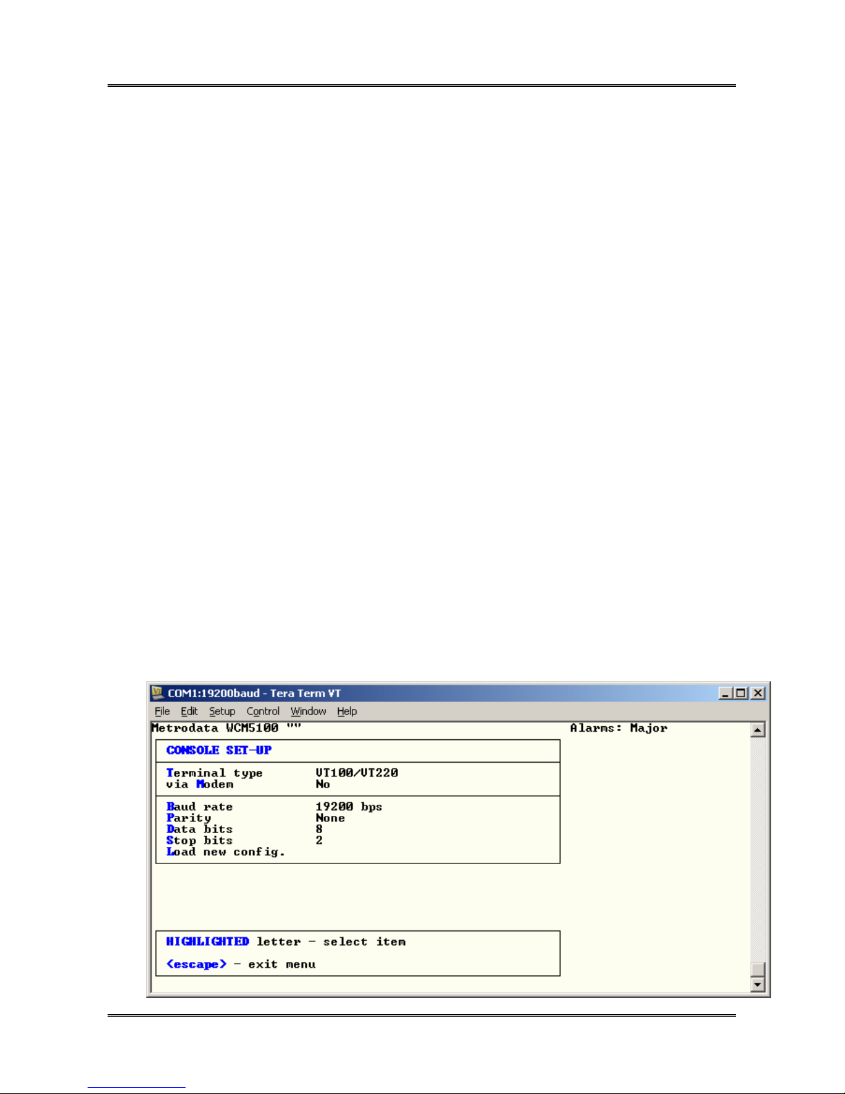
METRODATA LTD WCM5100
82 of 123
User Manual
5.4.2 Console Set Up
This menu defines the operating parameters of the terminal interface as shown:
Metrodata WCM5100 "" Alarms: Major
CONSOLE SET-UP
Terminal type TTY
via Modem No
Baud rate 19200 bps
Parity None
Data bits 8
Stop bits 2
Load new config.
First CAPITAL - select item
<escape> - exit menu
5.4.2.1 Terminal Type
The terminal type setting defines the output type of the user interface. There are 3
settings:
TTY A simple terminal interface sent line by line with scrolling screens and no
cursor control, or graphics
VT100 Enhanced display for VT100 emulation with highlighted characters, cursor
control and graphic borders
76-02-087 Rev D
Page 83

METRODATA LTD WCM5100
83 of 123
User Manual
ANSI Enhanced Vt100 mode
5.4.2.2 via Modem
The WCM supports management access via a dial up modem. When a call is connected
the terminal activates when DTR is raised by the modem, and will automatically disconnect
when DTR is negated.
Options
No Normal Terminal operation, 3 wire connection may be used
Yes Hardware Control based interface, full RS-232 interface needed including
DTR control signal
5.4.2.3 Baud Rate
This sets the baud rate for the terminal interface. The default setting is 19200baud.
The options are:
2400
4800
9600
19200
5.4.2.4 Parity
This sets the parity for the terminal interface. The default setting is None
The options are:
None
Odd
Even
76-02-087 Rev D
Page 84

METRODATA LTD WCM5100
84 of 123
User Manual
5.4.2.5 Data Bits
This sets the number of data bits per character for the terminal interface. The default
setting is 8.
The options are
8
7
5.4.2.6 Stop Bits
This sets the number of stop bits per character for the terminal interace. The default
setting is 2.
The options are
2
1
5.4.2.7 Load New Config
Once the parameters for the terminal interface have all been configured, they must be
loaded using the Load New Config command.
Once loaded, the new parameters will be in use, and the terminal emulator will also need
to be changed to match the required settings.
76-02-087 Rev D
Page 85

METRODATA LTD WCM5100
85 of 123
User Manual
5.5 Management Entity
The management entity menu defines the IP functionality of the WCM unit to enable
remote management access via the LAN, SFP or WAN ports.
Metrodata WCM5100 "" Alarms: Major
MANAGEMENT ENTITY
proXying <menu>
intErface <menu>
IP <menu>
UDP <menu>
tCp <menu>
sNmp <menu>
Telnet/SSH <menu>
tFtp <menu>
Ping <display>
First CAPITAL - select item
<escape> - exit menu
5.5.1 Proxying
The WCM product range supports proxy mode management where a local unit acts as a
proxy server and is configured with the IP address of the remote unit. The remote unit
may be simply installed in proxy client mode and it will assume all IP configuration from the
proxy server unit.
Proxying uses a proprietary extension to IEEE 802.3ah OAM and as such will only be
available for direct connections between units.
Metrodata WCM5100 "" Alarms: Major
PROXYING
Mode Disabled
First CAPITAL - select item
<escape> - exit menu
The default mode is determined by the bit switches on the underside of the unit with the
supported options being Disabled, Client, Server as below
76-02-087 Rev D
Page 86

METRODATA LTD WCM5100
86 of 123
User Manual
5.5.1.1 Server Mode Proxy
Setting the mode to Server enables the WCM unit to act as a proxy server to a group of
proxy clients attached to each of the ports. As a proxy server, the WCM unit will respond
to ARP for remote proxy IP addresses and communicate using an in band management
protocol with the client.
A client can be supported at the far end of each port of the unit, though in general, only
remote units connected via the VCG will be managed as proxy clients. The proxy client
set up menu is shown below:
Metrodata WCM5100 "" Alarms: Major
VCG
Proxying Enabled
Host interface Mgmt
DHCP Off
IP address 169.254.42.50
Net mask 255.255.0.0
First CAPITAL - select item
<escape> - exit menu
5.5.1.1.1 Proxying
For each client, proxying may be either Enabled or disabled.
Enabled Proxy mode active on this link,
Disabled Proxy mode disabled on this link
5.5.1.1.2 Host Interface
This is a display item only and cannot be changed. It indicates that the proxy client will
use the remote management interface.
5.5.1.1.3 DHCP
For each proxy client, DHCP may be enabled such that the IP address will be
administered automatically, otherwise it may be disabled, for manual IP address setting.
76-02-087 Rev D
Page 87

METRODATA LTD WCM5100
87 of 123
User Manual
5.5.1.1.4 IP Address
If DHCP is enabled, this will display the IP address served by the DHCP server, or if no
server is available it will have the initial default IP address of 169.254.42.xx where xx is
dependant upon which port the client is defined.
If DHCP is not enabled, enter the IP address for the remote device.
5.5.1.1.5 Network Mask
If DHCP is enabled, this will display the net mask served by the DHCP server, or if no
server is available it will have the default net mask of 255.255.0.0.
If DHCP is not enabled, enter the required net mask for the remote device.
5.5.1.2 Client Mode Proxy
When a device is set to be a Proxy client, it simply needs to be configured for which port
will be used for the proxy management. The client menu is as below:
Metrodata WCM5100 "" Alarms: Major
PROXYING
Mode Client
Interface VCG
First CAPITAL - select item
<escape> - exit menu
5.5.1.2.1 Interface
This toggle menu item selects which interface the proxy mode management will use.
Normally this will be the VCG, as this is the connection to the remote device.
76-02-087 Rev D
Page 88

METRODATA LTD WCM5100
88 of 123
User Manual
5.5.2 Interface
The interface menu is used to define the IP parameters for the unit management entity as
shown in the menu screen below:
Metrodata WCM5100 "" Alarms: Major
INTERFACE
State Up
Phys. address 0:c0:81:0:14:55
DHCP Off
IP addr 192.168.0.1
Net mask 255.255.255.0
AT table <display>
sTats. <display>
c-VLAN None
QinQ/S-VLAN 0
802.1p priority 0
Override incoming No
First CAPITAL - select item
<escape> - exit menu
5.5.2.1 State
This defines the administrative stat for the management entity. For management access
this must be set to up.
5.5.2.2 Physical Address
The physical address is the unique MAC address assigned to this unit. This address will
be of the form:
00:C0:81:xx:yy:zz where 00:C0:81 is the Metrodata OUI, and xx.yy.zz is the unit
identifier
76-02-087 Rev D
Page 89

METRODATA LTD WCM5100
89 of 123
User Manual
5.5.2.3 DHCP
The management entity can use DHCP for automatic IP address allocation, or it may be
disabled for manual administration.
Options
ON DHCP active, will try to get an IP address from a DHCP server, otherwise
will use the default IP address 169.254.42.42
OFF DHCP inactive, manual setting of IP address required.
5.5.2.4 IP Address
If DHCP is enabled, this will display the IP address allocated, or the default unit address of
169.254.42.42 if no server can be found.
If DHCP is not available, enter the required IP address.
5.5.2.5 Network Mask
If DHCP is enabled, this will display the net mask allocated, or the default mask of
255.255.0.0 if no server can be found.
If DHCP is not available, enter the required net mask
5.5.2.6 AT Table
The AT table is a display of the ARP resolutions that the WCM unit has made as shown
below:
Metrodata WCM5100 "" Alarms: Major
AT TABLE
--------
IP Address Ethernet Address Age
---------------------------------------
192.168.100.48 0.19.99.46.b7.8d 13
<Esc> - exit, <Enter> - refresh
76-02-087 Rev D
Page 90

METRODATA LTD WCM5100
90 of 123
User Manual
5.5.2.7 Statistics
The management interface provides a full set of MIB-2 IfTable statistics for the port as
shown below:
Metrodata WCM5100 "" Alarms: Major
Interface Statistics
--------------------
ifInOctets 12451
ifInUcastPkts 0
ifInNUcastPkts 141
ifInDiscards 0
ifInErrors 0
ifInUnknownProtos 0
ifOutOctets 0
ifOutUcastPkts 0
ifOutNUcastPkts 2
ifOutDiscards 0
ifOutErrors 0
ifOutQLen 0
<Esc> - exit, <Enter> - refresh
5.5.2.8 c-VLAN
Management access to the device may be tagged or untagged with a C-VLAN tag. This
tag is supported in both C-VLAN and QinQ/S-VLAN mode of operation.
If no C-Tag is required enter 0 for None, otherwise enter the VLAN ID for the management
connection in the range 1 to 4095.
5.5.2.9 QinQ/S-VLAN
When the device is in QinQ/S-VLAN mode, the management traffic will need to be
configured with an S-Tag defined by either the Access port default tag setting, or the SVID
used on a trunk port. The valid range is 1 to 4095.
5.5.2.10 802.1p Priority
When the Manager transmits a tagged packet, C-Tag, or S-Tag this priority setting is used
as the PCP info in the tag.
The valid range is 0 to 7, with 7 being highest priority.
76-02-087 Rev D
Page 91

METRODATA LTD WCM5100
91 of 123
User Manual
5.5.2.11 Override Incoming
The override incoming option allows the management frames to be promoted to the
configured priority level.
When override is enabled, a VLAN frame entering any port will have the PCP priority
overwritten with the value configured as the interface 802.1p priority.
Where the management VLAN transits the unit, the PCP value will be overwritten with the
new value on egress on a trunk port.
5.5.3 IP
The IP menu defines the layer 3 functionality for the manager interface and is shown
below:
Metrodata WCM5100 "" Alarms: Major
IP
default TTL 32
DSCP priority 0
Routing table <display>
Forwarding Disabled
Stats. <display>
First CAPITAL - select item
<escape> - exit menu
5.5.3.1 Default TTL
The default TTL setting is used as the TTL field in all management IP packets transmitted.
The default value is 32. The TTL value is decremented at each router hop and is intended
to prevent undelivered packets circulating the internet forever.
The valid range is 1 to 255
5.5.3.2 DSCP Priority
The configured DSCP value will be used in all IP frames transmitted by the manager. The
permitted range is 0 to 63 and where DSCP priority is used, should be set to match the
high priority setting of the network to prevent management traffic packet loss.
76-02-087 Rev D
Page 92

METRODATA LTD WCM5100
92 of 123
User Manual
5.5.3.3 Routing Table
Where management frames are destined for IP subnets that are not part of the local
subnet, a router must be used. To assist the manager in understanding how to route
frames to remote subnets, the IP routing table gives directions on how to reach each
remote destination.
The routing table with a default route added automatically by DHCP is shown below:
Metrodata WCM5100 "" Alarms: Major
Destination Next Hop I/f Type Prot. Age Mask
-----------------------------------------------------------------------------
192.168.100.0 0.0.0.0 Mgmt direct local 1653 255.255.255.0
0.0.0.0 192.168.100.113 Mgmt indirect local 1653 0.0.0.0
A - add entry
D - delete entry
any other key to exit:
5.5.3.3.1 Add a new Route
To add a new route, simply select Add Entry, and then enter the remote subnet, net mask
and next hop router address as shown below:
Metrodata WCM5100 "" Alarms: Major
Destination Next Hop I/f Type Prot. Age Mask
-----------------------------------------------------------------------------
192.168.100.0 0.0.0.0 Mgmt direct local 1772 255.255.255.0
0.0.0.0 192.168.100.113 Mgmt indirect local 1772 0.0.0.0
A - add entry
D - delete entry
any other key to exit:
Add route.
Destination: 192.168.0.0
Mask: 255.255.255.0
Next-hop: 192.168.100.229
Metrodata WCM5100 "" Alarms: Major
Destination Next Hop I/f Type Prot. Age Mask
-----------------------------------------------------------------------------
192.168.100.0 0.0.0.0 Mgmt direct local 1877 255.255.255.0
0.0.0.0 192.168.100.113 Mgmt indirect local 1877 0.0.0.0
192.168.0.0 192.168.100.229 Mgmt indirect local 0 255.255.255.0
A - add entry
D - delete entry
any other key to exit:
76-02-087 Rev D
Page 93

METRODATA LTD WCM5100
93 of 123
User Manual
5.5.3.3.2 Delete a Route
To delete a routing table entry, select delete entry and enter the IP address of the subnet
you wish to delete along with the net mask as shown
Metrodata WCM5100 "" Alarms: Major
Destination Next Hop I/f Type Prot. Age Mask
-----------------------------------------------------------------------------
192.168.100.0 0.0.0.0 Mgmt direct local 2019 255.255.255.0
0.0.0.0 192.168.100.113 Mgmt indirect local 2019 0.0.0.0
192.168.0.0 192.168.100.229 Mgmt indirect local 142 255.255.255.0
A - add entry
D - delete entry
any other key to exit:
Delete route.
Destination: 192.168.0.0
Mask: 255.255.255.0
Metrodata WCM5100 "" Alarms: Major
Destination Next Hop I/f Type Prot. Age Mask
-----------------------------------------------------------------------------
192.168.100.0 0.0.0.0 Mgmt direct local 2032 255.255.255.0
0.0.0.0 192.168.100.113 Mgmt indirect local 2032 0.0.0.0
A - add entry
D - delete entry
any other key to exit:
5.5.3.4 Forwarding
For products that provide a routing function, forwarding enables packets to be forwarded
between IP subnets, the WCM product range does not support routing and as such
forwarding is fixed as disabled.
5.5.3.5 Statistics
The Management IP Layer provides a comprehensive list of the IP and ICMP layer
statistics for assistance when diagnosing problems or monitoring performance in the
network.
76-02-087 Rev D
Page 94

METRODATA LTD WCM5100
94 of 123
User Manual
The available statistics are shown below:
Metrodata WCM5100 "" Alarms: Major
IP Statistics
------------ipInReceives 843
ipInHdrErrors 0
ipInAddrErrors 1
ipForwDatagrams 0
ipInUnknownProtos 0
ipInDiscards 0
ipInDelivers 842
ipOutRequests 2
ipOutDiscards 0
ipOutNoRoutes 0
ipReasmReqds 0
ipReasmOKs 0
ipReasmFails 0
ipFragOKs 0
ipFragFails 0
ipFragCreates 0
ipRoutingDiscards 0
press any key to continue
icmpInMsgs 0
icmpInErrors 0
icmpInDestUnreachs 0
icmpInTimeExcds 0
icmpInParmProbs 0
icmpInSrcQuenchs 0
icmpInRedirects 0
icmpInEchos 0
icmpInEchoReps 0
icmpInTimestamps 0
icmpInTimestampReps 0
icmpInAddrMasks 0
icmpInAddrMaskReps 0
icmpOutMsgs 0
icmpOutErrors 0
icmpOutDestUnreachs 0
icmpOutTimeExcds 0
icmpOutParmProbs 0
icmpOutSrcQuenchs 0
icmpOutRedirects 0
press any key to continue
icmpOutEchos 0
icmpOutEchoReps 0
icmpOutTimestamps 0
icmpOutTimestampReps 0
icmpOutAddrMasks 0
icmpOutAddrMaskReps 0
press any key to continue
76-02-087 Rev D
Page 95

METRODATA LTD WCM5100
95 of 123
User Manual
5.5.4 UDP
The UDP menu displays the port numbers used for SNMP Get and Set operations as well
as for Trap operation. These should not be altered.
Metrodata WCM5100 "" Alarms: Major
UDP
snmp Port 161
snmp Trap port 162
Stats. <display>
First CAPITAL - select item
<escape> - exit menu
5.5.4.1 Statistics
The UDP statistics menu displays the UDP statistics available in SNMP MIB-2 for a UDP
interface.
Metrodata WCM5100 "" Alarms: Major
UDP Statistics
-------------udpInDatagrams 940
udpNoPorts 929
udpInErrors 0
udpOutDatagrams 2
press any key to continue
5.5.5 TCP
The TCP menu is shown below:
Metrodata WCM5100 "" Alarms: Major
TCP
Stats. <display>
Conn table <display>
First CAPITAL - select item
<escape> - exit menu
76-02-087 Rev D
Page 96

METRODATA LTD WCM5100
96 of 123
User Manual
5.5.5.1 Statistics
The statistics menu displays the SNMP MIB-2 IfTable TCP statistics as shown:
Metrodata WCM5100 "" Alarms: Major
TCP Statistics
-------------tcpActiveOpens 1
tcpPassiveOpens 0
tcpAttemptFails 0
tcpEstabResets 0
tcpInSegs 13
tcpOutSegs 7
tcpRetransSegs 0
tcpInErrs 0
tcpOutRsts 0
press any key to continue
5.5.5.2 Connection Table
The Connection table displays a list, and status of TCP connections to the managent entity
of the WCM device.
Metrodata WCM5100 "" Alarms: Major
TCP CONNECTION TABLE
--------------------
State LocalAddress Loc Port RemAddress Rem Port
-----------------------------------------------------------established 192.168.100.39 23 192.168.100.48 3665
<Esc> - exit, <Enter> - refresh
Note, a maximum of four simultaneous TCP Telnet or SSH sessions may be opened at
any one time, further attempts to open sessions will lead to the session being rejected.
When enabled, TACACS+ always has a session available for use so cannot be locked out.
76-02-087 Rev D
Page 97

METRODATA LTD WCM5100
97 of 123
User Manual
5.5.6 SNMP Management
The WCM needs to be configured with the details of the SNMP Network Management
Station before the unit will generate traps, or respond to SNMP polls.
The SNMP parameters are configured using the SNMP menu found under the
Management menu
Metrodata WCM5100 "" Alarms: Major
SNMP
Read community public
Write community public
Trap community public
Managers <menu>
contact Person Metrodata Limited,Fortune House,
Crabtree Office Village,Eversl..
Node name
Location
Stats. <display>
trap Alarms <menu>
First CAPITAL - select item
<escape> - exit menu
5.5.6.1 Read/Write/Trap Community
To provide a level of security, communities are used to control access to the unit via
SNMP. Separate communities may be configured for Read/Write or Trap access.
5.5.6.2 Contact Person
The contact person is the SNMP MIB-2 system SysContact parameter, the default setting
is:
Metrodata Limited, Fortune House, Eversley Way, Egham, Surrey, TW20 8RY
The parameter may be up to 255 characters and should be configured to reflect the actual
installation requirements.
76-02-087 Rev D
Page 98

METRODATA LTD WCM5100
98 of 123
User Manual
5.5.6.3 Node Name
The node name is the SNMP MIB-2 system SysName parameter. By default this entry is
blank. The parameter may be up to 255 characters and should be configured to reflect the
actual installation requirements.
5.5.6.4 Location
The location is the SNMP MIB-2 system SysLocation parameter. By default this entry is
blank. The parameter may be up to 255 characters and should be configured to reflect the
actual installation requirements.
5.5.6.5 Managers
To enable access to the WCM using SNMP, specific manager addresses must be
configured. Once a Manager is assigned, the WCM will respond to polls and generate
traps for that manager. The WCM supports up to 10 configured Network Management
Stations. The manager may be configured to operate as SNMP V1 or V2c
The Add Manager Menu is as below:
Metrodata WCM5100 "" Alarms: Major
ADD MANAGER
IP address 0.0.0.0
Access rights None
receives Traps No
snmp Version SNMPv2c
Remove manager
First CAPITAL - select item
<escape> - exit menu
The IP address is the IP address of the assigned Network Management Station.
76-02-087 Rev D
Page 99

METRODATA LTD WCM5100
99 of 123
User Manual
The Access Rights supported are:
None No Access
Read Only Only SNMP GET access is allowed
Read-Write SNMP GET/SET access allowed
The Receive Traps parameter determines whether, under alarm conditions, Traps should
be sent to this Network Manager.
The SNMP version may be configured for the manager to support either SNMP V1 or
SNMP V2c.
5.5.6.6 Statistics
The WCM management entity provides a set of SNMP MIB-2 IfTable SNMP statistics for
the interface:
Metrodata WCM5100 "" Alarms: Major
SNMP Statistics
--------------snmpInPkts 0
snmpOutPkts 0
snmpInBadVersions 0
snmpInBadCommunityNames 0
snmpInBadCommunityUses 0
snmpInASNParseErrs 0
snmpInTooBigs 0
snmpInNoSuchNames 0
snmpInBadValues 0
snmpInReadOnlys 0
snmpInGenErrs 0
snmpInTotalReqVars 0
snmpInTotalSetVars 0
snmpInGetRequests 0
snmpInGetNexts 0
snmpInSetRequests 0
snmpInGetResponses 0
snmpInTraps 0
press any key to continue:
snmpOutTooBigs 0
snmpOutNoSuchNames 0
snmpOutBadValues 0
snmpOutGenErrs 0
snmpOutGetRequests 0
snmpOutGetNexts 0
snmpOutSetRequests 0
snmpOutGetResponses 0
snmpOutTraps 0
press any key to continue
76-02-087 Rev D
Page 100

METRODATA LTD WCM5100
100 of 123
User Manual
5.5.6.7 Trap Alarms
The WCM units have a large number of interfaces, all with a large number of alarms and
possible sources of trap generation. This menu allows the individual alarm conditions to
be defined as to whether they will force a trap to be generated or not.
There is a separate configuration menu for each port type within the unit as shown below:
Metrodata WCM5100 "" Alarms: Major
TRAP ALARMS
lan1 <menu>
lan2 <menu>
SFP <menu>
VCG <menu>
WAN <menu>
vc-4 <menu>
vc-3 <menu>
First CAPITAL - select item
<escape> - exit menu
5.5.6.7.1 LAN Port Trap Definitions
Metrodata WCM5100 "" Alarms: Major
LAN1
1 - LKDN Trap
3 - LLF Trap
5 - OAM Trap
6 - CFM Trap
First CAPITAL - select item
<escape> - exit menu
The alarm definitions for the LAN port are as follows
LKDN Link Down, this Alarm indicates that the link is not operational due to
either a cable not being attached, the remote device either powered
down or not connected, or problems with auto negotiation or auto
MDI/MDIX selection
LLF Link Loss Forward, this Alarm indicates that the port has been forced
down due to the link state forwarding source having an alarm.
OAM Loss of OAM ( 802.3ah ) contact with peer device
76-02-087 Rev D
 Loading...