

Page 1

WCM1100 (E1/T1)
WCM3100 (E3/DS-3)
WCM-Serial
Managed Ethernet Extender
V7.17
Quick Start Guide
DATE: 21st August 2012
DOCUMENT NO: 76-02-082
REVISION: D
PREPARED BY: Ian Banbrook
Metrodata Ltd
Fortune House, Crabtree Office Village
Eversley Way, Egham Surrey, TW20 8RY, UK
Tel +44 1 784 744700
Fax: +44 1 784 744730
E-Mail: [email protected]
Page 2

METRODATA LTD WCM1100 / WCM3100 / WCM-Serial
Quick Start Guide
METRODATA LTD
No part of this publication may be reproduced, transmitted,
transcribed, stored in a retrieval system, or translated into any
language or computer language, in any form or by any means,
electronic, mechanical, magnetic, optical, chemical, manual or
otherwise, without the prior written permission of
Metrodata Ltd, Fortune House,
Crabtree Office Village, Eversley Way,
2 of 75
Egham, Surrey, TW20 8RY, United Kingdom
.
DISCLAIMER
Metrodata Ltd makes no representations or warranties with respect
to the contents hereof and specifically disclaims any implied
warranties or merchantability or fitness for any particular purpose.
Further, Metrodata Ltd reserves the right to revise this publication
and to make changes from time to time in the content hereof without
obligation of Metrodata Ltd to notify any person of such revision or
changes.
Copyright 2012 by Metrodata Ltd,
All Rights Reserved
76-02-082 Rev D
Page 3

METRODATA LTD WCM1100 / WCM3100 / WCM-Serial
Quick Start Guide
Document Revision History
3 of 75
6th December 2010 A Document Created
29th June 2011 B Document updated for Software version
30th January 2012 C Upgraded for V7.14 application software,
21st August 2012 D Updated fro 7.17 Application software and
7.9 and merged with WCM3100 product
manual.
and added support for WCM-Serial
product
base label updates
76-02-082 Rev D
Page 4

METRODATA LTD WCM1100 / WCM3100 / WCM-Serial
4 of 75
Quick Start Guide
TABLE OF CONTENTS
1 INTRODUCTION..........................................................................................................8
2 WCM APPLICATIONS...............................................................................................10
2.1
WCM Normal Mode ........................................................................................................................................10
2.2
WCM VLAN Trunk Mode .............................................................................................................................. 10
2.3
VLAN Trunk Mode.......................................................................................................................................... 11
2.4
S-Tag Mode....................................................................................................................................................... 11
3 QUICK START CONFIGURATION............................................................................12
3.1
Base Label.........................................................................................................................................................12
3.1.1 WCM1100 Base Label .................................................................................................................................. 12
3.1.2 WCM3100 Base Label .................................................................................................................................. 13
3.1.3 WCM-Serial Base Label................................................................................................................................13
3.2
Cold Start the Unit ...........................................................................................................................................14
3.2.1 Bit Switches...................................................................................................................................................14
3.2.1.1 Bitswitch 1, Boot Mode 0 ....................................................................................................................14
3.2.1.2 Bitswitch 2, Boot Mode 1 ....................................................................................................................14
3.2.1.3 Bitswitch 3, DHCP............................................................................................................................... 14
3.2.1.4 Bitswitch 4, Framing............................................................................................................................15
3.2.1.5 Bitswitch 5, Timing Mode ...................................................................................................................15
3.2.1.6 Bitswitch 6, Interface Mode.................................................................................................................16
3.2.1.7 Bitswitch 7, SFP Mode ........................................................................................................................ 16
3.2.1.8 Bitswitch 8, Factory Default ................................................................................................................ 16
3.3
Access the WCM............................................................................................................................................... 17
3.4
Logging onto WCM.......................................................................................................................................... 17
3.4.1 User Interface Navigation..............................................................................................................................18
3.5
Configure the WAN interface.......................................................................................................................... 19
3.5.1 WCM1100 E1 Configuration ........................................................................................................................ 19
3.5.2 WCM3100 E3 Configuration ........................................................................................................................ 20
3.5.3 WCM3100 DS-3 Configuration .................................................................................................................... 20
3.5.4 WCM-Serial Configuration ...........................................................................................................................21
3.6
Set IP Address...................................................................................................................................................22
3.7
Set Default Route.............................................................................................................................................. 23
3.8
Save the Configuration..................................................................................................................................... 24
3.9
Warm Start to activate the configuration ......................................................................................................25
4 ADVANCED CONFIGURATION................................................................................26
4.1
System Configuration.......................................................................................................................................26
76-02-082 Rev D
Page 5

METRODATA LTD WCM1100 / WCM3100 / WCM-Serial
Quick Start Guide
5 of 75
4.1.1 Setting the Time and Date ............................................................................................................................. 27
4.1.2 Setting the Node Name.................................................................................................................................. 28
4.1.3 Password........................................................................................................................................................29
4.1.3.1 Password Recovery.............................................................................................................................. 29
4.1.4 ‘View’ User ...................................................................................................................................................29
4.1.5 Welcome Screen............................................................................................................................................30
4.1.6 Warm Start.....................................................................................................................................................32
4.1.7 Cold Start.......................................................................................................................................................32
4.2
Data Port Configuration ..................................................................................................................................33
4.2.1 LAN Port .......................................................................................................................................................34
4.2.1.1 State...................................................................................................................................................... 35
4.2.1.2 Link Status ........................................................................................................................................... 35
4.2.1.3 Auto Negotiation..................................................................................................................................35
4.2.1.4 Speed.................................................................................................................................................... 35
4.2.1.5 Duplex.................................................................................................................................................. 35
4.2.1.6 Negotiated............................................................................................................................................35
4.2.1.7 MDI/MDIX..........................................................................................................................................36
4.2.1.8 Counters............................................................................................................................................... 36
4.2.1.9 OAM .................................................................................................................................................... 37
4.2.1.9.1 OAM Mode ..................................................................................................................................... 37
4.2.1.9.2 OAM Status.....................................................................................................................................38
4.2.1.10 Mgmt traffic.........................................................................................................................................38
4.2.1.11 VLAN ID ............................................................................................................................................. 39
4.2.1.12 QinQ S-TAG ID...................................................................................................................................39
4.2.1.13 default Priority ..................................................................................................................................... 39
4.2.2 SFP Port......................................................................................................................................................... 40
4.2.2.1 SFP Type..............................................................................................................................................41
4.2.2.2 State...................................................................................................................................................... 41
4.2.2.3 Link State.............................................................................................................................................41
4.2.2.4 Speed.................................................................................................................................................... 41
4.2.2.5 Auto Negotiation..................................................................................................................................41
4.2.2.6 Negotiated............................................................................................................................................41
4.2.2.7 SFP Info ............................................................................................................................................... 42
4.2.2.8 Counters............................................................................................................................................... 42
4.2.2.9 OAM .................................................................................................................................................... 43
4.2.2.9.1 OAM Mode ..................................................................................................................................... 43
4.2.2.9.2 OAM Status.....................................................................................................................................44
4.2.2.10 mGmt Traffic ....................................................................................................................................... 44
4.2.2.11 VLAN ID ............................................................................................................................................. 45
4.2.2.12 QinQ S-TAG ID...................................................................................................................................45
4.2.2.13 default Priority ..................................................................................................................................... 45
4.2.3 WCM1100 WAN Port ...................................................................................................................................46
4.2.3.1 State...................................................................................................................................................... 47
4.2.3.2 Interface ...............................................................................................................................................47
Timing ........................................................................................................................................................... 47
4.2.3.3...................................................................................................................................................................... 47
4.2.3.4 RX Sensitivity...................................................................................................................................... 47
4.2.3.5 Framing................................................................................................................................................ 48
4.2.3.6 Allocation.............................................................................................................................................48
4.2.3.7 CRC-4 .................................................................................................................................................. 49
4.2.3.8 sigNalling.............................................................................................................................................49
4.2.3.9 Counters............................................................................................................................................... 49
4.2.3.10 OAM .................................................................................................................................................... 50
4.2.3.10.1 OAM Mode.................................................................................................................................... 50
4.2.3.10.2 OAM Status ...................................................................................................................................51
mGmt Traffic.................................................................................................................................................51
4.2.3.11.................................................................................................................................................................... 51
4.2.3.12 VLAN ID ............................................................................................................................................. 52
76-02-082 Rev D
Page 6

METRODATA LTD WCM1100 / WCM3100 / WCM-Serial
Quick Start Guide
6 of 75
4.2.3.13 QinQ S-TAG ID...................................................................................................................................52
4.2.3.14 default Priority ..................................................................................................................................... 52
4.2.4 WCM3100 WAN Port ...................................................................................................................................53
4.2.4.1 State...................................................................................................................................................... 54
4.2.4.2 Interface ...............................................................................................................................................54
4.2.4.3 Timing.................................................................................................................................................. 54
4.2.4.4 TX Line Build Out (DS-3 mode Only) ................................................................................................54
4.2.4.5 Framing................................................................................................................................................ 55
4.2.4.6 Counters............................................................................................................................................... 55
4.2.4.7 OAM .................................................................................................................................................... 56
4.2.4.7.1 OAM Mode ..................................................................................................................................... 56
4.2.4.7.2 OAM Status.....................................................................................................................................57
4.2.4.8 mGmt Traffic ....................................................................................................................................... 57
4.2.4.9 VLAN ID ............................................................................................................................................. 58
4.2.4.10 QinQ S-TAG ID...................................................................................................................................58
4.2.4.11 default Priority ..................................................................................................................................... 58
4.2.5 WCM-Serial WAN Port Configuration......................................................................................................... 59
4.2.5.1 State...................................................................................................................................................... 60
4.2.5.2 Interface ...............................................................................................................................................60
4.2.5.3 Mode .................................................................................................................................................... 61
4.2.5.4 Controls................................................................................................................................................ 61
4.2.5.5 State...................................................................................................................................................... 61
4.2.5.6 Counters............................................................................................................................................... 62
4.2.5.7 OAM .................................................................................................................................................... 63
4.2.5.7.1 OAM Mode ..................................................................................................................................... 63
4.2.5.7.2 OAM Status.....................................................................................................................................64
4.2.5.8 mGmt Traffic ....................................................................................................................................... 64
4.2.5.9 VLAN ID ............................................................................................................................................. 65
4.2.5.10 QinQ S-TAG ID...................................................................................................................................65
4.2.5.11 default Priority ..................................................................................................................................... 65
4.2.6 Encapsulation................................................................................................................................................. 66
4.2.6.1 Encapsulation....................................................................................................................................... 66
4.2.6.1.1 HDLC.............................................................................................................................................. 66
4.2.6.1.1.1 HDLC FCS...............................................................................................................................66
4.2.6.1.1.2 Strip MAC FCS........................................................................................................................67
4.2.6.1.1.3 Payload Scrambler ................................................................................................................... 67
4.2.6.1.2 X.86................................................................................................................................................. 67
4.2.6.1.2.1 Strip MAC FCS........................................................................................................................67
4.2.6.1.2.2 Payload Scrambler ................................................................................................................... 67
4.2.6.1.2.3 VCAT....................................................................................................................................... 67
4.2.6.1.3 GFP ................................................................................................................................................. 68
4.2.6.1.3.1 Strip MAC FCS........................................................................................................................68
4.2.6.1.3.2 Payload Scrambler ................................................................................................................... 68
4.2.6.1.3.3 VCAT....................................................................................................................................... 68
4.2.6.2 Flow Control ........................................................................................................................................ 68
4.2.6.3 Max Frame Size ................................................................................................................................... 68
4.2.6.4 Priority Table ....................................................................................................................................... 69
4.2.6.4.1 802.1p Mode.................................................................................................................................... 69
4.2.6.4.2 IP DSCP Mode................................................................................................................................ 69
4.2.7 Traffic Isolation............................................................................................................................................. 70
4.2.8 RSTP..............................................................................................................................................................70
4.3
SNMP Management .........................................................................................................................................71
4.3.1 Read/Write/Trap Community........................................................................................................................71
4.3.2 Contact Person...............................................................................................................................................71
4.3.3 Node Name.................................................................................................................................................... 72
4.3.4 Location......................................................................................................................................................... 72
4.3.5 Managers ....................................................................................................................................................... 72
76-02-082 Rev D
Page 7

METRODATA LTD WCM1100 / WCM3100 / WCM-Serial
7 of 75
Quick Start Guide
4.4
Saving the Configuration................................................................................................................................. 73
5 TFTP SOFTWARE UPDATE .....................................................................................74
5.1
TFTP Configuration.........................................................................................................................................74
5.1.1 Client Mode................................................................................................................................................... 74
5.1.2 Server Mode ..................................................................................................................................................75
76-02-082 Rev D
Page 8

METRODATA LTD WCM1100 / WCM3100 / WCM-Serial
8 of 75
Quick Start Guide
1 INTRODUCTION
This guide instructs the user in the use of the WCM1100 Managed Ethernet Extender over
E1, WCM3100 Managed Ethernet Extender over E3/DS-3 or WCM-Serial Managed
Ethernet Extender of Serial Connections This guide describes the functionality of
Software Release 7.14.
Throughout this document, the term WCM will be used to describe generic functions,
whilst WCM1100, WCM3100 or WCM-Serial will be used for product specific areas.
The Metrodata WCM allows for the extension of an Ethernet Service over a Wide Area
Network Connection. The WCM is a managed unit allowing for the effective demarcation
between LAN and WAN services. Management of the WCM is achieved using either
Telnet or SNMP via either the LAN or WAN ports.
In cases where management is not required, or undesired, the WCM can operate
standalone, with simple configuration options provided using bit switches located on the
underside of the unit.
The Metrodata WCM is a managed, multi port Ethernet Switch with a WAN uplink. The
WCM provides two 10/100/1000BaseT Auto Negotiating, Auto Switching Ports as well as a
single SFP port supporting either 1000Base-X or 100Base-FX SFP modules. The WCM
operates as a layer 2 bridge and as such may be used to extend a LAN segment over a
WAN link.
The WCM has an internal LAN switch offering full wire-speed switching between ports.
The WCM uses MAC address filtering to filter all local traffic and only forward traffic
destined for remote stations. Each of the WCM’s LAN ports support automatic cross-over
switching and will therefore connect directly to a Hub/Switch/Router or PC End Station.
The WCM has support for both tagged and untagged frames, with both VLAN C-Tag, and
Provider Bridge S-Tag (QinQ) modes supported.
The WCM supports either IP DSCP, or IEEE802.1p based traffic prioritisation with
outgoing traffic being queued in one of four priority queues.
The WCM supports link OAM, IEEE802.3ah and RSTP for loop prevention.
The WCM encapsulates the Ethernet traffic for transport across the WAN link. The WCM
supports HDLC in all cases, and for framed modes X.86 and GFP encapsulations are also
supported. Internal packet buffers enable the WCM to smooth out bursty traffic and
prevent packet loss as the higher layer protocols rate adapt to the WAN capacity.
The WCM1100 E1 port supports unframed, framed (with or without CRC-4 ) or fractional
(Nx64k) operating modes.
The WCM3100 supports unframed or framed operation, supporting E3 G.832 or DS-3 CBit Framing modes.
76-02-082 Rev D
Page 9

METRODATA LTD WCM1100 / WCM3100 / WCM-Serial
9 of 75
Quick Start Guide
The WCM-Serial supports unframed operation only, and normally operates as a serial DTE
interface for connection to a carrier NTU. An optional DCE mode, allows for back to back
operation.
76-02-082 Rev D
Page 10
METRODATA LTD WCM1100 / WCM3100 / WCM-Serial
10 of 75
Quick Start Guide
2 WCM APPLICATIONS
2.1 WCM Normal Mode
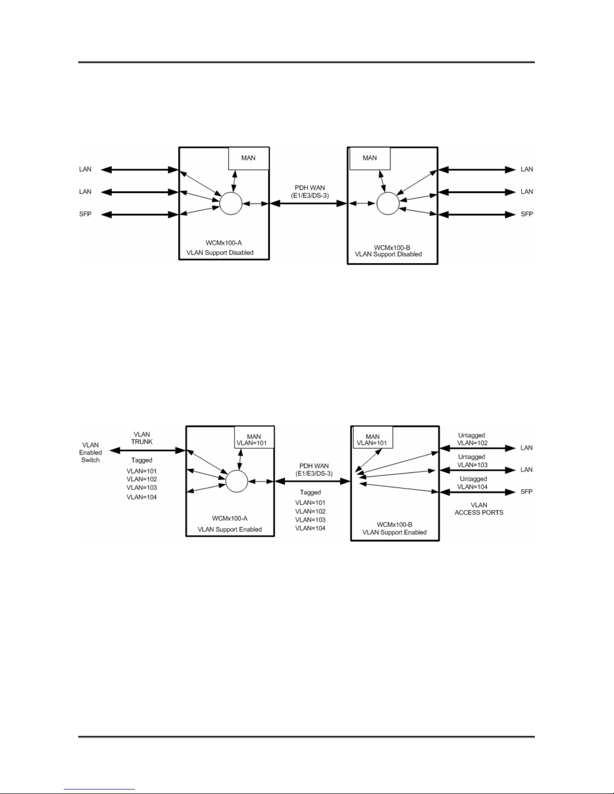
In this application, the WCM is operating with Traffic Isolation Disabled. In this mode, the
WCM acts as a simple, layer 2, 5 port switch with packets being switched based on MAC
address alone. The WCM supports both local and remote switching, and forwarding over
the WAN trunk.
Management traffic is not isolated from the through data traffic, and both units may be
managed from any port.
2.2 WCM VLAN Trunk Mode
In this application, WCM-A is connected to a VLAN enabled LAN switch. The LAN switch
is configured as a VLAN trunk and all packets are tagged with VLAN Tags. WCM-A is
operating with VLAN support enabled but all ports defined as Trunks. A VLAN ID is
allocated to the Manager and thus management traffic is isolated from the user traffic and
the management VLAN, in this case 101, can be used to manage the WCM’s. WCM1100B is configured with VLAN support enabled but each port is configured as an access port
and isolated to a single VLAN.
Trunk ports expect packets to be tagged, whilst access ports expect untagged packets and
will add tag and priority to incoming packets.
76-02-082 Rev D
Page 11
METRODATA LTD WCM1100 / WCM3100 / WCM-Serial
11 of 75
Quick Start Guide
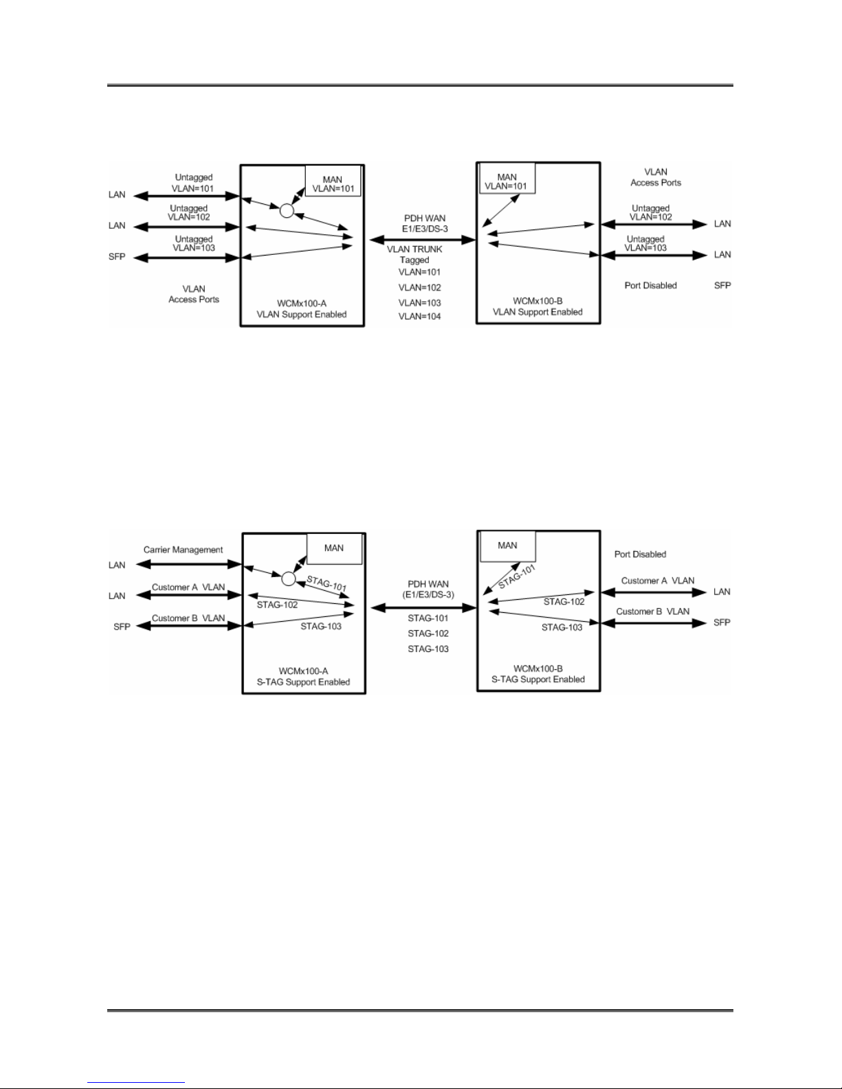
2.3 VLAN Trunk Mode
In this mode, both WCM units have VLAN support enabled, and all ports are defined as
access ports VLAN 101 is used as the management VLAN and in unit WCM1100-A the
VLAN group 101 includes the LAN Port 1, the Manager and the PDH WAN port. At the
remote end, The SFP port is disabled to prevent customer access to the WCM manager.
2.4 S-Tag Mode
In this mode, the WCM adds a, port based, S-TAG to all incoming traffic. Where customer
traffic is already VLAN tagged, this leads to double tagging or ‘QinQ’ operation. The use
of the S-TAG enables the carrier to isolate customer traffic. Carrier management traffic is
carried with a separate S-Tag giving management access to both units, and on the
customer site the external management access is disabled.
76-02-082 Rev D
Page 12
METRODATA LTD WCM1100 / WCM3100 / WCM-Serial
12 of 75
Quick Start Guide
3 QUICK START CONFIGURATION
The following guide gives a simple, quick start introduction to configuring the WCM for
Normal Mode operation as shown in section 2.1
3.1 Base Label
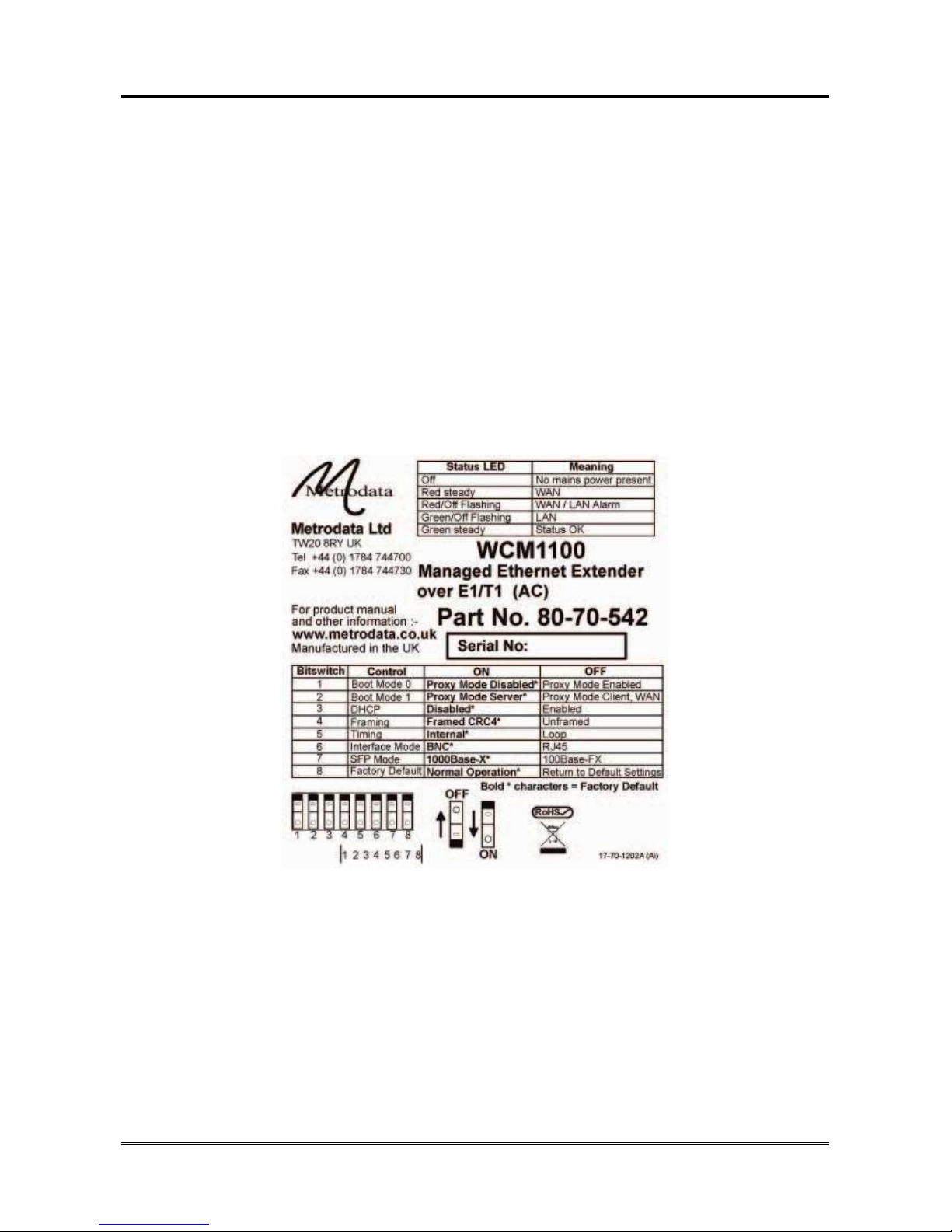
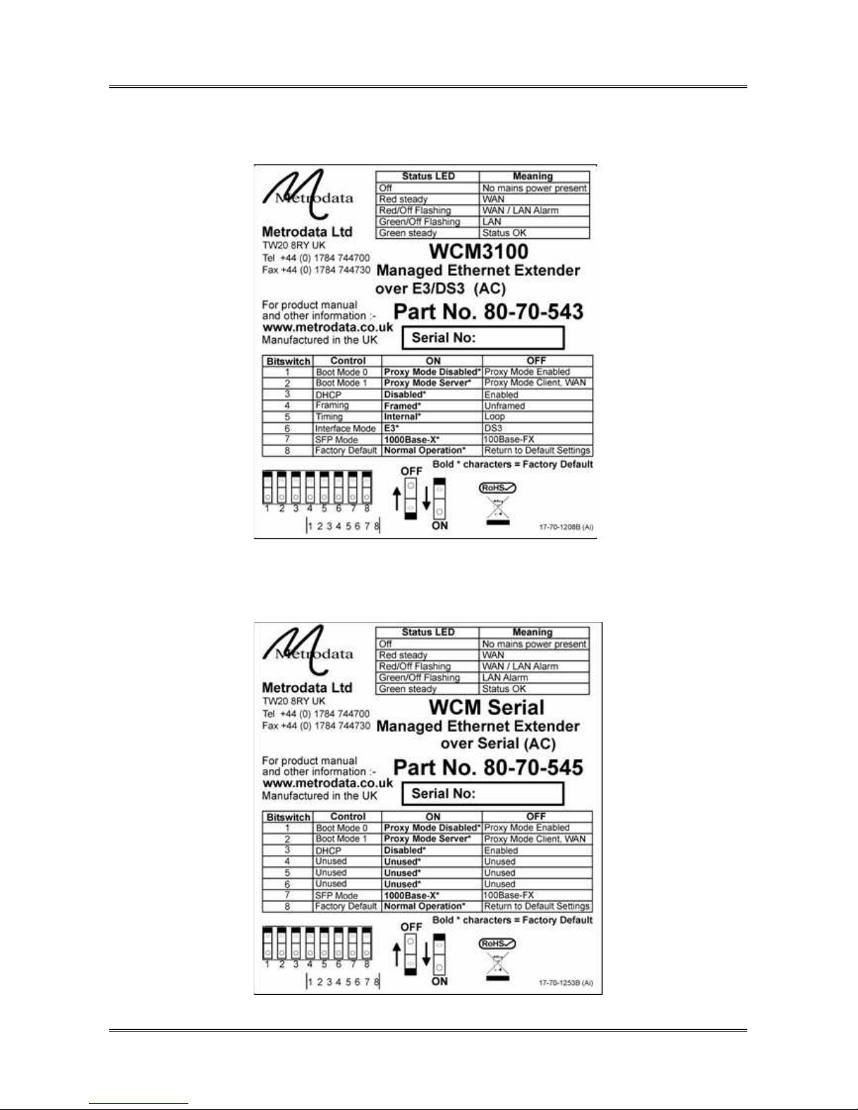
There is a label on the underside of each product which defines the cold start default
configuration of the unit.
3.1.1 WCM1100 Base Label
76-02-082 Rev D
Page 13
METRODATA LTD WCM1100 / WCM3100 / WCM-Serial
Quick Start Guide
3.1.2 WCM3100 Base Label
13 of 75
3.1.3 WCM-Serial Base Label
76-02-082 Rev D
Page 14

METRODATA LTD WCM1100 / WCM3100 / WCM-Serial
14 of 75
Quick Start Guide
3.2 Cold Start the Unit
When a WCM is shipped from the factory it will be in the default condition, however with
previously used equipment this may not be the case. To return the unit to the default state
will require a power cycle and configuration of the bit switches.
The underside of the unit has a set of accessible bit switches and a label, as shown below
for the two products:
Ensure all other bit switches are in the desired default positions.
To cold start the unit, first set bit switch 8 (Cold Start) to the OFF (Return to Default
Settings) position. Power up the WCM, wait for the Status LED to come on in any state,
and then power down. To return to normal mode, return bit switch 8 to the ON (Normal
Operation) position.
3.2.1 Bit Switches
The bit switches are also used to define the default settings and should be set accordingly
as defined below:
3.2.1.1 Bitswitch 1, Boot Mode 0
This bitswitch is used to determine whether the IP proxy management mode is enabled or
not. IP proxy mode utilises OAM to remotely manage a WCM device.
ON Proxy Mode Disabled
OFF Proxy Mode Enabled,
I
3.2.1.2 Bitswitch 2, Boot Mode 1
This bitswitch is ignored if Proxy Mode is disabled. When Proxy mode is enabled, this
mode determines whether the unit acts as Master/Server, or Slave/Client.
ON Proxy Mode, Server
OFF Proxy Mode, Client
3.2.1.3 Bitswitch 3, DHCP
This bitswitch enables DHCP for IP address allocation.
ON DHCP Disabled
OFF DHCP Enabled
76-02-082 Rev D
Page 15

METRODATA LTD WCM1100 / WCM3100 / WCM-Serial
Quick Start Guide
3.2.1.4 Bitswitch 4, Framing
This bitswitch determines the operating mode of the PDH WAN interface.
ON E1 G.703, G.704 Framed with CRC-4 Enabled (WCM1100)
E3 G.703, G.832 Framed (WCM3100)
DS-3 G.703 C-Bit Framed (WCM3100)
OFF E1/E3/DS-3 G.703 Unframed
This bitswitch is unused on the WCM-Serial which does not offer framed modes.
15 of 75
3.2.1.5 Bitswitch 5, Timing Mode
This bitswitch determines the timing source for the PDH WAN interface
ON Internal Timing
OFF Loop Timing
Note, it is vital that one end of PDH WAN link is set to internal, as loop/loop will give an
unstable system.
This bitswitch is unused on the WCM-Serial, timing is defined by the auto sensing cable
type used.
76-02-082 Rev D
Page 16

METRODATA LTD WCM1100 / WCM3100 / WCM-Serial
16 of 75
Quick Start Guide
3.2.1.6 Bitswitch 6, Interface Mode
This bitswitch selects between the two optional interface modes,
For WCM1100, E1 Interface
ON BNC, Unbalanced 75Ohm
OFF RJ45, Balanced 120Ohm
For WCM3100,
ON E3 G.703
OFF DS-3 G.703
This bitswitch is not used on the WCM-Serial as the interface mode is automatically
selected by the auto sensing cables.
3.2.1.7 Bitswitch 7, SFP Mode
This bitswitch is used to force the configuration of the SFP interface to match the SFP type
inserted.
ON 1000Base-X SFP
OFF 100Base-FX SFP
3.2.1.8 Bitswitch 8, Factory Default
This bitswitch will clear the stored configuration and return the unit to the default settings
as defined by the bit switches.
ON Normal Operation
OFF Factory Cold Start, load default settings
The main use of this switch it to ensure a unit can be accessed in the even that the
password has been lost.
76-02-082 Rev D
Page 17

METRODATA LTD WCM1100 / WCM3100 / WCM-Serial
17 of 75
Quick Start Guide
3.3 Access the WCM
Initial access to the WCM is made using the Terminal Port on the rear panel of the unit.
The Terminal port defaults to 19200baud, 8bit, No Parity, 1 Stop Bit. The 9 Way D-Type
is configured as a DCE port with standard pinout as shown below:
Pin Direction
Signal
1 out DCD
2 out RXD*
3 In TXD*
4 In DTR
5 Signal Ground*
6 out DSR
7 In RTS
8 out CTS
9 no connect
Figure 3.3 Terminal Port Connector Pin Configuration
3.4 Logging onto WCM
The initial access to the WCM must use a terminal connected to the terminal port.
The WCM has a password protected, menu driven user interface. When a management
session is connected to the WCM, the welcome banner will be displayed as shown:
Metrodata WCM1100: Local connection to “”
Password (‘view’ to view only ) :
or
Metrodata WCM3100: Local connection to “”
Password (‘view’ to view only ) :
or
Metrodata WCM-Serial: Local connection to “”
Password (‘view’ to view only ) :
76-02-082 Rev D
Page 18

METRODATA LTD WCM1100 / WCM3100 / WCM-Serial
18 of 75
Quick Start Guide
At the prompt, enter the password to gain access to the WCM. The default password is
the product name, ie “wcm1100”, “wcm3100” or “wcm-serial”. For security, the password
is obscured with an asterisk (*) being displayed for each character typed. An incorrect
password will lead to the welcome banner being redisplayed. A correct password will lead
onto the main set up menu as shown below:
Metrodata WCM "" Alarms: Major
MAIN SET-UP
Global status <display>
alarm eXtension <menu>
Data port set-up <menu>
V.24 set-up <menu>
Management <menu>
System <menu>
Update EEPROM
Testing <menu>
Performance data <menu>
First CAPITAL - select item
<escape> - exit menu
3.4.1 User Interface Navigation
The WCM user interface is a simple, menu based interface. Each selectable item may be
selected by typing the first capital of the option, e.g. for “Data port set-up” type <D>1 or
<d>. Sometimes, where multiple items have the same starting letter the selection capital
will not be the first letter, e.g. “alarm eXtension” which is selected with <X> or <x>.
On the right side of the display is a list of what is below each item. This could be:
<menu> This indicates a sub-menu will be entered
<display> This indicates an information screen will be displayed. This may be
status or statistics.
Additional keys may be used to navigate the menu system:
<ESC> This will exit the current menu, or log out from the main set up menu.
<SPACE> This will toggle through a list of selectable options
<ENTER> This will select an item
1
Encapsulating an item within < > indicates a key press is required, for example <D>
means type D.
76-02-082 Rev D
Page 19
METRODATA LTD WCM1100 / WCM3100 / WCM-Serial
19 of 75
Quick Start Guide
3.5 Configure the WAN interface
In order for two WCM units to communicate they must be connected using the PDH WAN
port. The WAN interface must be configured to match the network NTU configuration.
The WAN port is configured by selecting the Data Port Set-Up Menu,
Metrodata WCM "" Alarms: Major
DATA PORT SET-UP
lan1 <menu>
lan2 <menu>
SFP <menu>
WAN <menu>
Encapsulation <menu>
traffic Isolation <menu>
RSTP <menu>
First CAPITAL - select item
<escape> - exit menu
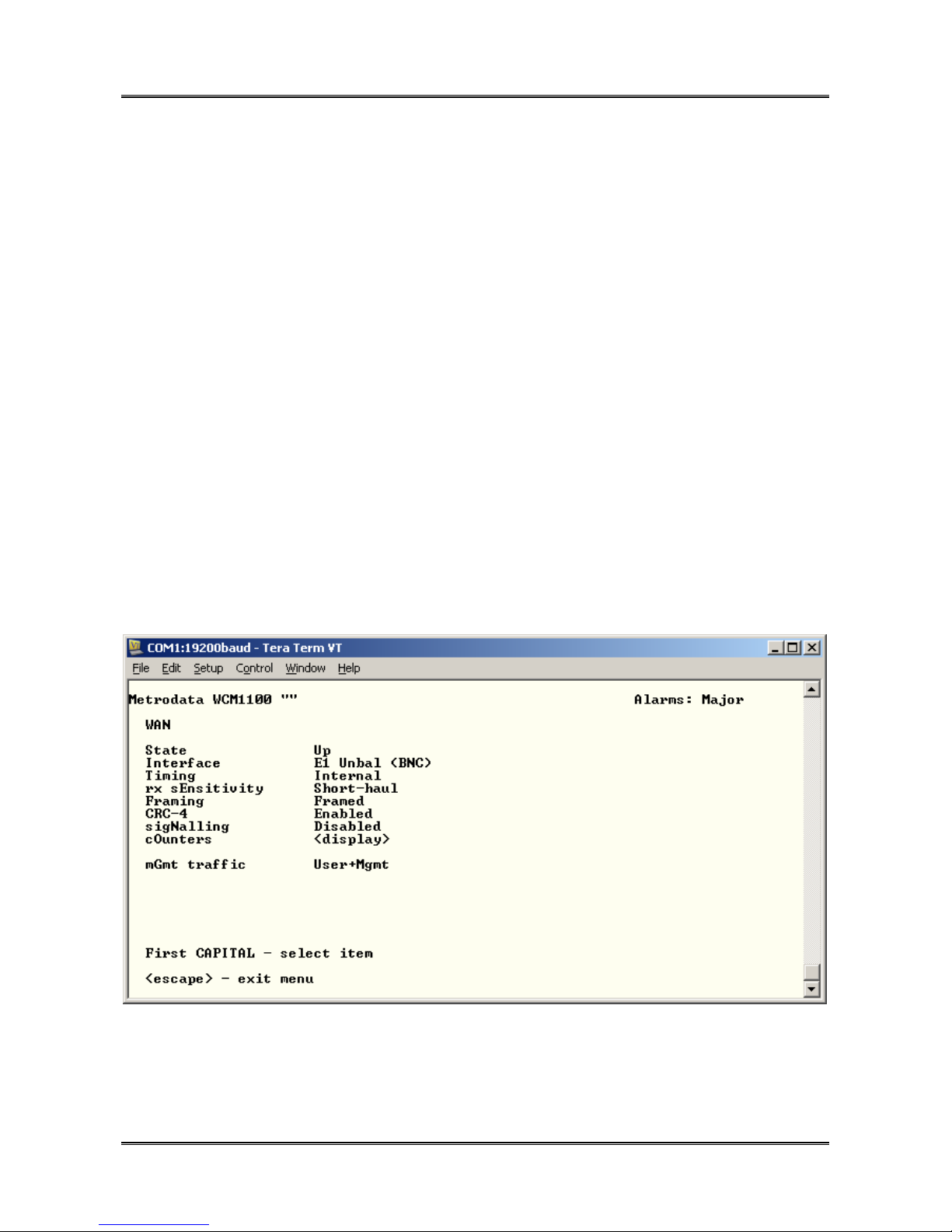
3.5.1 WCM1100 E1 Configuration
Ensure that the interface, timing and framing modes are correctly set to match the network
NTU settings.
76-02-082 Rev D
Page 20
METRODATA LTD WCM1100 / WCM3100 / WCM-Serial
Quick Start Guide
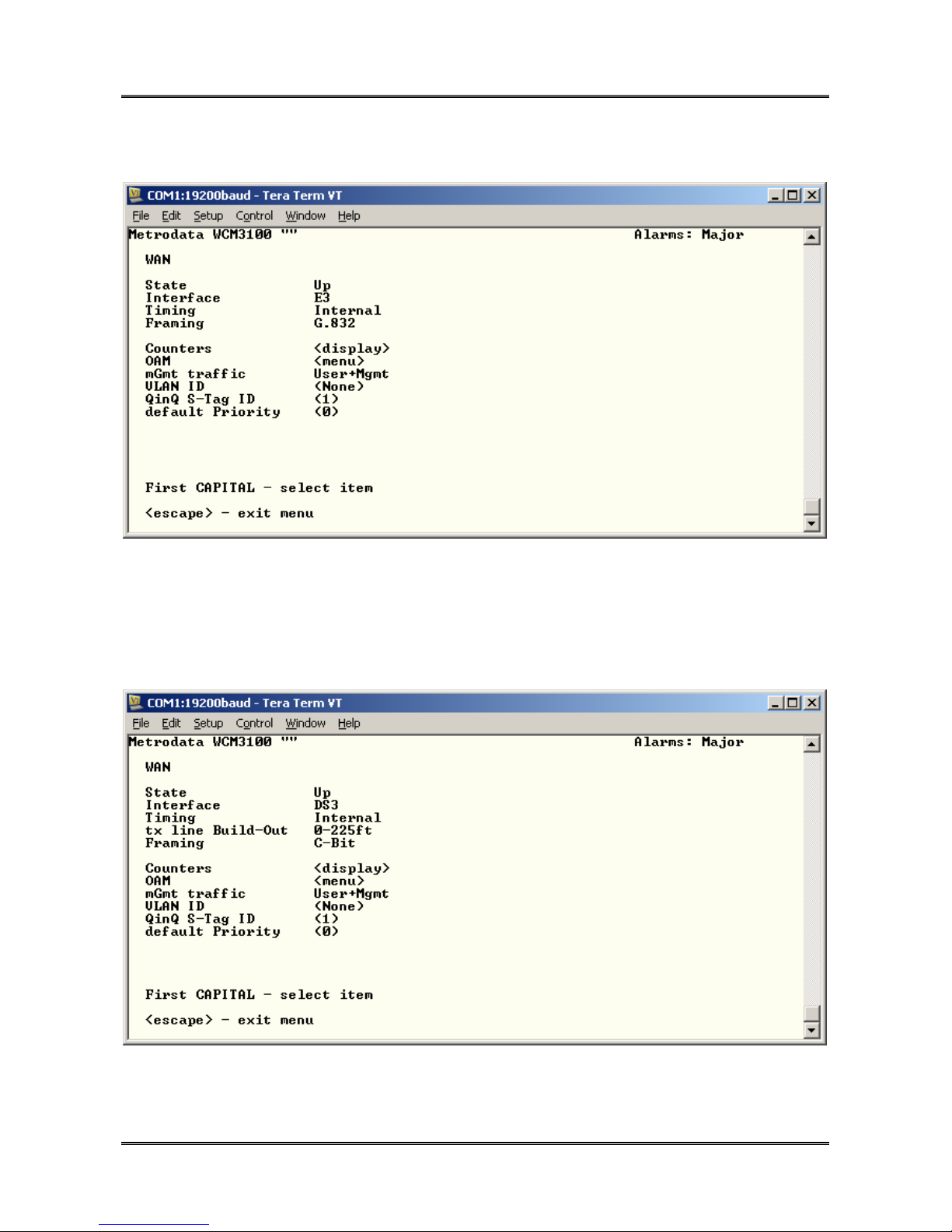
3.5.2 WCM3100 E3 Configuration
20 of 75
For the E3 interface, the framing mode ( G.832 or Unframed ) must be configured as well
as the interface timing.
3.5.3 WCM3100 DS-3 Configuration
When DS-3 mode is selected, the framing mode ( C-Bit or Unframed ) must be set as well
as the interface timing. Additionally, the transmitter power must be configured by setting
the line build out to support either short ( <225ft ) or longer cable runs.
76-02-082 Rev D
Page 21
METRODATA LTD WCM1100 / WCM3100 / WCM-Serial
21 of 75
Quick Start Guide
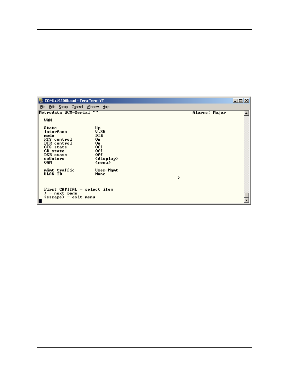
3.5.4 WCM-Serial Configuration
The WCM-Serial has a multi-serial interface which can support many different electrical
interface standards. The multi serial interface is presented on an HD60 connector and is
compatible with standard Cisco serial cables. The interface automatically senses the
cable type that is connected, and configures itself accordingly.
The WAN Configuration Menu when a CAB-V35-MT is fitted is shown below:
The WCM-Serial always operates in an unframed mode.
76-02-082 Rev D
Page 22

METRODATA LTD WCM1100 / WCM3100 / WCM-Serial
Quick Start Guide
3.6 Set IP Address
From the Main Setup Menu, select Management,
Metrodata WCM "" Alarms: Major
MANAGEMENT
proXying <menu>
intErface <menu>
IP <menu>
UDP <menu>
tCp <menu>
sNmp <menu>
Telnet <menu>
tFtp <menu>
Ping <display>
First CAPITAL - select item
<escape> - exit menu
22 of 75
and then the Interface Menu.
Metrodata WCM "" Alarms: Major
INTERFACE
State Up
Phys. address 0:c0:81:0:13:85
DHCP Off
IP addr 169.254.42.42
Net mask 255.255.0.0
Broadcast address from bit 1
AT table <display>
sTats. <display>
VLAN ID (0)
QinQ S-Tag ID (1)
802.1p priority 0
traffic isOlation <menu>
First CAPITAL - select item
<escape> - exit menu
76-02-082 Rev D
Page 23

METRODATA LTD WCM1100 / WCM3100 / WCM-Serial
Quick Start Guide
To change the IP settings for installation:
DHCP For operation in a DHCP enabled network and automatic
IP address allocation set this parameter to ON to enable
DHCP address allocation.
IP Address If DHCP is not used, you must manually assign the
required IP address for correct installation into the
network. ( Note the default IP address is set to
169.254.42.42 )
Net mask If DHCP is not used, you must assign the required network
mask for correct installation into the network.
3.7 Set Default Route
From the Main Setup Menu, select Management, then IP,
23 of 75
Metrodata WCM "" Alarms: Major
IP
default TTL 32
Max reassy time 0 sec
DSCP priority 0
Routing table <display>
Forwarding Disabled
Stats. <display>
First CAPITAL - select item
<escape> - exit menu
then select the Routing Table menu and set the default route,
Metrodata WCM "" Alarms: Major
Destination Next Hop I/f Type Prot. Age Mask
-----------------------------------------------------------------------------
169.254.0.0 0.0.0.0 Mgmt direct local 157 255.255.0.0
A - add entry
D - delete entry
any other key to exit:
Add route.
Destination: 0.0.0.0
Mask: 0.0.0.0
Next-hop: 169.254.0.254
76-02-082 Rev D
Page 24

METRODATA LTD WCM1100 / WCM3100 / WCM-Serial
24 of 75
Quick Start Guide
Metrodata WCM "" Alarms: Major
Destination Next Hop I/f Type Prot. Age Mask
-----------------------------------------------------------------------------
169.254.0.0 0.0.0.0 Mgmt direct local 182 255.255.0.0
0.0.0.0 169.254.0.254 Mgmt indirect local 0 0.0.0.0
A - add entry
D - delete entry
any other key to exit:
Add a new route table entry with destination and mask as 0.0.0.0 and configure the next
hop as required.
3.8 Save the Configuration
From the Main Set Up menu, select the Update EEPROM option to save the configuration
to non volatile memory. Answer ‘Y’ at the prompt.
Metrodata WCM "" Alarms: Major
MAIN SET-UP
Global status <display>
alarm eXtension <menu>
Data port set-up <menu>
V.24 set-up <menu>
Management <menu>
System <menu>
Update EEPROM
Testing <menu>
Performance data <menu>
First CAPITAL - select item
<escape> - exit menu
76-02-082 Rev D
Page 25

METRODATA LTD WCM1100 / WCM3100 / WCM-Serial
Quick Start Guide
3.9 Warm Start to activate the configuration
From the Main Set Up Menu, select system and then Warm start.
Metrodata WCM "" Alarms: Major
SYSTEM
Time & date <menu>
Node name
Password ********
'View' user Enabled
weLcome screen <menu>
Software version 7.14
Output config <display>
Input config
Warm start
Cold start
Event logs <menu>
First CAPITAL - select item
<escape> - exit menu
25 of 75
Select the Warm Start ooption and the unit will now reboot and will operate as a simple
managed, layer 2 bridge.
76-02-082 Rev D
Page 26

METRODATA LTD WCM1100 / WCM3100 / WCM-Serial
26 of 75
Quick Start Guide
4 ADVANCED CONFIGURATION
4.1 System Configuration
The system menu provides the basic administrative configuration items for the WCM and
should be configured first. The System Menu is shown below:
Metrodata WCM "" Alarms: Major
SYSTEM
Time & date <menu>
Node name
Password ********
'View' user Enabled
weLcome screen <menu>
Software version 7.14
Output config <display>
Input config
Warm start
Cold start
Event logs <menu>
First CAPITAL - select item
<escape> - exit menu
76-02-082 Rev D
Page 27

METRODATA LTD WCM1100 / WCM3100 / WCM-Serial
27 of 75
Quick Start Guide
4.1.1 Setting the Time and Date
The WCM does not provide a non volatile Real Time Clock, instead it uses NTP to set the
date and time following power up. In applications where NTP is not available, the WCM
defaults to providing a simple uptime display.
To configure the NTP parameters, select the “Time and date” menu from the “System”
menu. The menu is as below:
Metrodata WCM "" Alarms: Major
TIME & DATE
local Time 00:05:29
local Date Sat 1/1/2000
system up time 0d0h5m29s
time Zone GMT+0
NTP server 0.0.0.0
last sync never
Sync now
First CAPITAL - select item
<escape> - exit menu
If NTP is available, then the following parameters need to be set,
Time Zone +/-12 Since NTP uses GMT, time zone adjustment allows the
correct time to be configured wherever the units are
deployed globally.
NTP Server Enter the IP address of the network NTP server.
According to the NTP protocol, the WCM will wait for a random period of between 1 and 5
minutes before requesting an NTP update.
If NTP is not available, then the user can manually enter the time and date, however since
these are non volatile and not maintained over a power cycle it is not recommended.
Additionally the system up time parameter is provided.
76-02-082 Rev D
Page 28

METRODATA LTD WCM1100 / WCM3100 / WCM-Serial
28 of 75
Quick Start Guide
4.1.2 Setting the Node Name
To enable identification of the WCM, it is useful to enter a meaningful name for the unit.
The node name is entered as a string of up to 32 alpha numeric characters, including
spaces.
Metrodata WCM "WCM Node A" Alarms: Major
SYSTEM
Time & date <menu>
Node name WCM Node A
Password ********
'View' user Enabled
weLcome screen <menu>
Software version 7.14
Output config <display>
Input config
Warm start
Cold start
Event logs <menu>
First CAPITAL - select item
<escape> - exit menu
Once a node name has been defined, in this case “WCM Node A” it is displayed at the top
of each user menu to assist the user identify which device is currently connected.
76-02-082 Rev D
Page 29

METRODATA LTD WCM1100 / WCM3100 / WCM-Serial
29 of 75
Quick Start Guide
4.1.3 Password
The password for the WCM may be changed from the system menu. The default
password is the product name, ie “wcm1100”, “wcm3100” or “wcm-serial”, however for
deployment a more secure password may be required.
To change the unit password, select “Password” from the system menu. The WCM will
display the following:
Enter new password
Password >
Enter the new password, up to 16 alphanumeric characters. For security, each character
is shown on the screen as an asterisk “*”. Once the new password is entered, the display
changes to
Enter new password
Password > ***********
Verify>
Re-enter the new password. If the password is correctly verified the unit will assume the
new password for the next logon.
4.1.3.1 Password Recovery
If for any reason, the password for access to the WCM is lost, the unit may be cold started
by using bit switch 8 which will return the unit to the default factory configuration. The
default factory password is the product name, “wcm1000”, “wcm3100” or “wcm-serial”.
Note, that returning the unit to factory default will erase the configuration memory and all
configuration items including IP address will be lost.
4.1.4 ‘View’ User
The WCM supports two levels of access: admin and view. An Admin user has full access
rights over the WCM configuration. A view user has read only access to the configuration.
In some cases it may be desirable to prevent the “view” user access.
To disable the view user access, select the View User menu item and toggle the option to
disabled. It will now not be possible to log in with the “view” password.
76-02-082 Rev D
Page 30

METRODATA LTD WCM1100 / WCM3100 / WCM-Serial
30 of 75
Quick Start Guide
4.1.5 Welcome Screen
By default, the initial access to the WCM will display the welcome banner as shown below:
Metrodata WCM: Local connection to “WCM Node A”
Password (‘view’ to view only ) :
However, it is possible to customize the welcome banner to give further information about
the unit, or to inform the user of access restrictions.
To configure the welcome screen select the “welcome screen” menu item which will lead
to the menu:
Metrodata WCM "WCM Node A" Alarms: Major
WELCOME SCREEN
Welcome screen Disabled
First CAPITAL - select item
<escape> - exit menu
If a customized welcome is required, change to enabled and the menu will change as
shown below:
Metrodata WCM "WCM Node A" Alarms: Major
WELCOME SCREEN
Welcome screen Enabled
1st line
2nd line
3rd line
4th line
5th line
6th line
7th line
8th line
Clear all text
Display screen <display>
First CAPITAL - select item
<escape> - exit menu
76-02-082 Rev D
Page 31

METRODATA LTD WCM1100 / WCM3100 / WCM-Serial
31 of 75
Quick Start Guide
To configure the Welcome Screen enter each line using alpha numeric characters with
each line supporting upto 80 characters as in the example below:
Metrodata WCM "WCM Node A" Alarms: Major
WELCOME SCREEN
Welcome screen Enabled
1st line This is an example
2nd line of a Welcome Banner
3rd line
4th line Welcome to the WCM
5th line
6th line
7th line Please enter the password>
8th line
Clear all text
Display screen <display>
First CAPITAL - select item
<escape> - exit menu
Once the welcome message has been defined, it may be displayed using the display
screen option, and for this example, the Display Screen shows:
Metrodata WCM3100 "WCM1x00 Node A" Alarms: Major
WELCOME SCREEN
--------------
This is an example
of a Welcome Banner
Welcome to the WCM
Please enter the password>
<Escape> - exit, other key - refresh
which leads to a welcome banner displayed as follows when a management session is
started up:
76-02-082 Rev D
Page 32

METRODATA LTD WCM1100 / WCM3100 / WCM-Serial
32 of 75
Quick Start Guide
This is an example
of a Welcome Banner
Welcome to the WCM
Please enter the password>
password ('view' to view only):
4.1.6 Warm Start
A warm Start will force the WCM to restart and reload the configuration from the EEPROM.
Note, any changes to configuration that have not been saved to the EEPROM will be lost.
When a user issues a warm start request, the WCM will indicate that a warm start is in
progress and then close the connection.
4.1.7 Cold Start
Cold Start will return the WCM to the factory default condition and as defined by the bit
switch settings.
Note, that a cold start will erase IP addresses and Routing Table entries and it is therefore
highly likely that remote access will be lost following a cold start.
For this reason a cold start request must be confirmed before it is actioned, and the user
must type Y at the prompt
Returns all settings to defaults!
Are you sure?
Once confirmed the unit will restart, and default the internal non volatile configuration
memory and return the unit to the default state.
76-02-082 Rev D
Page 33

METRODATA LTD WCM1100 / WCM3100 / WCM-Serial
33 of 75
Quick Start Guide
4.2 Data Port Configuration
This section deals with the configuration of each of the user data port types including
WAN, and LAN ports. A simple configuration will be shown for each type of port.
The port configuration is accessed from the main setup menu by selecting the data port
menu. The data port menu gives the following options
Metrodata WCM "" Alarms: Major
DATA PORT SET-UP
lan1 <menu>
lan2 <menu>
SFP <menu>
WAN <menu>
Encapsulation <menu>
traffic Isolation <menu>
RSTP <menu>
First CAPITAL - select item
<escape> - exit menu
76-02-082 Rev D
Page 34

METRODATA LTD WCM1100 / WCM3100 / WCM-Serial
34 of 75
Quick Start Guide
4.2.1 LAN Port
The WCM has two external copper LAN ports which by default operate in
10/100/1000BaseT auto negotiating, auto crossover mode. The LAN ports are presented
on RJ45 connectors and support access to the other external local LAN ports, the
management processor or the WAN forwarding port.
The LAN port menu allows for configuration of the LAN port parameters and VLAN settings
Metrodata WCM "" Alarms: Major
LAN1
State Up
link status Down
spEed 1000M
Duplex Full
Auto-negotiation Enabled
negotiated ---
MDI/MDIX Auto
Counters <display>
OAM <menu>
mGmt traffic User+Mgmt
VLAN ID (None)
QinQ S-Tag ID (1)
>
First CAPITAL - select item
> - next page
<escape> - exit menu
and the next page
Metrodata WCM "" Alarms: Major
LAN1
<
default Priority (0)
First CAPITAL - select item
< - prev page
<escape> - exit menu
76-02-082 Rev D
Page 35

METRODATA LTD WCM1100 / WCM3100 / WCM-Serial
35 of 75
Quick Start Guide
4.2.1.1 State
The port state is the administrative state of this port. The state may be up or down. When
‘UP’, the port is enabled and will generate a Major Alarm if the link is physically down.
When in the ‘DOWN’ state, the port is disabled.
4.2.1.2 Link Status
The Link Status is a display of the current link status. If the link is up, the link status will
show UP and vice versa. Only when the link status is UP are the operating parameters
valid when in auto negotiating mode.
4.2.1.3 Auto Negotiation
The port may be configured to automatically determine the optimal operating parameters
for link speed and duplex. Alternatively, it may be disabled to enable configuration of fixed
operating parameters.
Note, the Auto Negotiating algorithm works optimally with a link partner that also supports
auto negotiation. For operation where one end of a link uses fixed configuration and does
not negotiate, it must be noted that only Speed, 10 or 100M, can be determined, the auto
negotiating node will fall back to use half duplex. 1000M operation requires auto
negotiation to be used.
4.2.1.4 Speed
When in auto negotiating mode, the speed displayed is the highest that will be advertised
to the link partner. In non auto negotiating mode, the speed is manually set by the user.
4.2.1.5 Duplex
When in auto negotiating mode, the duplex displayed is the highest that will be advertised
to the link partner. In non auto negotiating mode, the duplex is manually set by the user.
4.2.1.6 Negotiated
This item displays the actual operating parameters of the link following auto negotiation
and may take the values:
1000/FD 1000Mbps, Full Duplex
100/FD 100Mbps, Full Duplex
100/HD 100Mbps, Half Duplex
10/FD 10Mbps, Full Duplex
10/HD 10Mbps, Half Duplex
76-02-082 Rev D
Page 36

METRODATA LTD WCM1100 / WCM3100 / WCM-Serial
36 of 75
Quick Start Guide
4.2.1.7 MDI/MDIX
By default, the ports support automatic crossover configuration when required. The port
may be configured as follows:
AUTO Auto Sense and configure
MDI Present MDI interface, direct connection to switch
MDIX Present MDIX Interface, direct connection to PC
4.2.1.8 Counters
Each LAN port provides a set of counters supporting the basic MIB-2 SNMP parameters
as below:
Interface Statistics
------------------------ ifInOctets 808916
ifInUcastPkts 2012
ifInNUcastPkts 5600
ifInDiscards 0
ifInErrors 0
ifInUnknownProtos 0
ifOutOctets 186612
ifOutUcastPkts 2562
ifOutNUcastPkts 1
ifOutDiscards 0
ifOutErrors 0
76-02-082 Rev D
Page 37

METRODATA LTD WCM1100 / WCM3100 / WCM-Serial
37 of 75
Quick Start Guide
4.2.1.9 OAM
The WCM supports IEEE 802.3ah Link OAM which may be configured on a per port basis:
Metrodata WCM "" Alarms: Major
OAM
Mode Active
Status <display>
First CAPITAL - select item
<escape> - exit menu
4.2.1.9.1 OAM Mode
The port may be configured to be:
Disabled OAM packets not generated, and discarded
Active OAM status requests generated once per second
Passive OAM Status Updates will be generated in response to Status
Requests.
76-02-082 Rev D
Page 38

METRODATA LTD WCM1100 / WCM3100 / WCM-Serial
38 of 75
Quick Start Guide
4.2.1.9.2 OAM Status
When two ports are running OAM, the status screen enables the user to determine the
status of the remote device.
Metrodata WCM "" Alarms: Major
OAM STATUS
----------
| Local | Local | Peer | Peer | Peer | Peer
| Status | Support | Mode | MAC address | VendorInfo | Support
---------+----------+---------+------+-------------+------------+-------LAN1 Fault L
Remote Status
------------Not available
<Escape> - exit, other key - refresh
Where the peer device is another Metrodata device, proprietary extensions to OAM are
used to report further peer status information.
4.2.1.10 Mgmt traffic
In order to provide traffic isolation this parameter defines what type of traffic passes over
this interface. The options are as below
User + Mgmt This port carries user and management traffic. Management frames
are switched to the processor, whilst user frames are switched to the
WAN port.
User only This port only carries user traffic and ALL frames are switched to the
WAN port with no access to the management processor
Mgmt only This port only carries Management Traffic and all frames are
forwarded to the management processor with no frames forwarded to
the WAN port.
76-02-082 Rev D
Page 39

METRODATA LTD WCM1100 / WCM3100 / WCM-Serial
39 of 75
Quick Start Guide
4.2.1.11 VLAN ID
If the Traffic Isolation mode is set to VLAN then the LAN port may be configured as either
ACCESS, or TRUNK.
A port is configured as an Access Port if it is assigned to a VLAN, ie given a VLAN ID
between 1 and 4095. All frames ingressing this port will have a VLAN Tag added, and on
egress will have the tag removed. This configuration item defines the VLAN ID which will
be added and may be in the range (1 to 4095 ). One or more ports may be assigned to the
same VLAN and packets will then only switch between those ports and trunk ports.
A port is configured as TRUNK, if the VLAN ID 0 or none is selected. In this case frames
ingress, or egress, with tags unchanged. A trunk is assumed to be a member of all VLANs
4.2.1.12 QinQ S-TAG ID
If the Traffic Isolation mode is set to QinQ then the LAN port may be assigned provider
mode Service Tag, S-TAG. and all frames ingressing this port will have the S-Tag added.
This configuration item defines the S-TAG ID which will be added and may be in the range
(1 to 4095 ). One or more ports may be assigned the same S-TAG and packets will then
only switch between those ports and the WAN interface.
In QinQ mode, ingress packets may be tagged or untagged and all will have a single STAG stripped before egress.
4.2.1.13 default Priority
When the traffic isolation mode is VLAN, this is the priority value that is added with the
VLAN ID during ingress at an Access Port. In QinQ mode, untagged packets are given
this default priority, whilst tagged packets promote the C-TAG priority to the S-TAG
priority.
76-02-082 Rev D
Page 40

METRODATA LTD WCM1100 / WCM3100 / WCM-Serial
40 of 75
Quick Start Guide
4.2.2 SFP Port
The SFP port configuration menu is accessed via the data port set up menu and is as
shown below:
Metrodata WCM "" Alarms: Major
SFP
sfp type 1000BASE-SX
State Up
link status Down
spEed 1000M
Auto-negotiation Enabled
negotiated ---
sfp Info <display>
Counters <display>
OAM <menu>
mGmt traffic User+Mgmt
VLAN ID (None)
QinQ S-Tag ID (1)
>
First CAPITAL - select item
> - next page
<escape> - exit menu
and next page
Metrodata WCM "" Alarms: Major
OAM
Mode Active
Status <display>
First CAPITAL - select item
<escape> - exit menu
76-02-082 Rev D
Page 41

METRODATA LTD WCM1100 / WCM3100 / WCM-Serial
41 of 75
Quick Start Guide
4.2.2.1 SFP Type
This display item indicates the type of SFP fitted. This value is read from the SFP device
itself and is a decode of the interface type bytes according to the SFP MSA definition.
Metrodata supplied SFP devices will indicate the SFP type, however some lower cost,
lower quality SFP devices may not be correctly programmed an will indicate “UNKNOWN”
as the device type cannot be determined.
If no SFP is fitted, this will show “NOT FITTED”
4.2.2.2 State
This setting defines the administrative state of the port and may be UP or DOWN. When
the state is DOWN, no alarm processing is performed. If an SFP is not fitted, it is
important to change this state to DOWN to prevent the SFP MAJOR alarm being
generated.
4.2.2.3 Link State
When the SFP is fitted, this displays the operational state of the link and also may be UP
or DOWN.
4.2.2.4 Speed
The speed setting replicates the underside switch 7 setting and selects between
1000BaseX and 100BaseFX operating mode.
This setting should be set to match the SFP device inserted.
Alternatively, this can be set to AUTO, in which case the software will read the device type
from the SFP and select either 1000BaseX or 100BaseFX determined by the information
read back.
4.2.2.5 Auto Negotiation
When operating in 1000baseX mode, Auto negotiation must be enabled.
4.2.2.6 Negotiated
When Auto Negotiation is enabled, this displays the mode negotiated.
76-02-082 Rev D
Page 42

METRODATA LTD WCM1100 / WCM3100 / WCM-Serial
Quick Start Guide
4.2.2.7 SFP Info
This menu displays further information regarding the SFP device:
Metrodata WCM "" Alarms: Major
EoPDH SFP Info Slot: 0
------------- Transmit
Status Type Vendor Part No. Wavelength
---------------------------------------------------------------------- Good 1000BASE-SX HG GENUINE MXPD-248S-F 850nm
<Escape> - exit, other key – refresh
42 of 75
4.2.2.8 Counters
The counters option displays the MIB-2 statistics gathered for the WAN port.
Metrodata WCM "" Alarms: Major
Interface Statistics
--------------------
ifInOctets 0
ifInUcastPkts 0
ifInNUcastPkts 0
ifInDiscards 0
ifInErrors 0
ifInUnknownProtos 0
ifOutOctets 0
ifOutUcastPkts 0
ifOutNUcastPkts 0
ifOutDiscards 0
ifOutErrors 0
<Escape> - exit, C - clear, other key - refresh
76-02-082 Rev D
Page 43

METRODATA LTD WCM1100 / WCM3100 / WCM-Serial
43 of 75
Quick Start Guide
4.2.2.9 OAM
The WCM supports IEEE 802.3ah Link OAM which may be configured on a per port basis:
Metrodata WCM "" Alarms: Major
OAM
Mode Active
Status <display>
First CAPITAL - select item
<escape> - exit menu
4.2.2.9.1 OAM Mode
The port may be configured to be:
Disabled OAM packets not generated, and discarded
Active OAM status requests generated once per second
Passive OAM Status Updates will be generated in response to Status
Requests.
76-02-082 Rev D
Page 44

METRODATA LTD WCM1100 / WCM3100 / WCM-Serial
44 of 75
Quick Start Guide
4.2.2.9.2 OAM Status
When two ports are running OAM, the status screen enables the user to determine the
status of the remote device.
Metrodata WCM "" Alarms: Major
OAM STATUS
----------
| Local | Local | Peer | Peer | Peer | Peer
| Status | Support | Mode | MAC address | VendorInfo | Support
---------+----------+---------+------+-------------+------------+-------SFP Fault L
Remote Status
------------Not available
<Escape> - exit, other key - refresh
Where the peer device is another Metrodata device, proprietary extensions to OAM are
used to report further peer status information.
4.2.2.10 mGmt Traffic
In order to provide traffic isolation this parameter defines what type of traffic passes over
this interface. The options are as below
User + Mgmt This port carries user and management traffic. Management frames
are switched to the processor, whilst user frames are switched to the
LAN ports.
User only This port only carries user traffic and ALL frames are switched to the
LAN ports with no access to the management processor
Mgmt only This port only carries Management Traffic and all frames are
forwarded to the management processor with no frames forwarded to
the LAN ports. This state MUST be avoided as it would prevent any
user data passing over the E1 interface.
76-02-082 Rev D
Page 45

METRODATA LTD WCM1100 / WCM3100 / WCM-Serial
45 of 75
Quick Start Guide
4.2.2.11 VLAN ID
If the Traffic Isolation mode is set to VLAN then the LAN port may be configured as either
ACCESS, or TRUNK.
A port is configured as an Access Port if it is assigned to a VLAN, ie given a VLAN ID
between 1 and 4095. All frames ingressing this port will have a VLAN Tag added, and on
egress will have the tag removed. This configuration item defines the VLAN ID which will
be added and may be in the range (1 to 4095 ). One or more ports may be assigned to the
same VLAN and packets will then only switch between those ports and trunk ports.
A port is configured as TRUNK, if the VLAN ID 0 or none is selected. In this case frames
ingress, or egress, with tags unchanged. A trunk is assumed to be a member of all VLANs
4.2.2.12 QinQ S-TAG ID
If the Traffic Isolation mode is set to QinQ then the LAN port may be assigned provider
mode Service Tag, S-TAG. and all frames ingressing this port will have the S-Tag added.
This configuration item defines the S-TAG ID which will be added and may be in the range
(1 to 4095 ). One or more ports may be assigned the same S-TAG and packets will then
only switch between those ports and the WAN interface.
In QinQ mode, ingress packets may be tagged or untagged and all will have a single STAG stripped before egress.
4.2.2.13 default Priority
When the traffic isolation mode is VLAN, this is the priority value that is added with the
VLAN ID during ingress at an Access Port. In QinQ mode, untagged packets are given
this default priority, whilst tagged packets promote the C-TAG priority to the S-TAG
priority.
76-02-082 Rev D
Page 46
METRODATA LTD WCM1100 / WCM3100 / WCM-Serial
Quick Start Guide
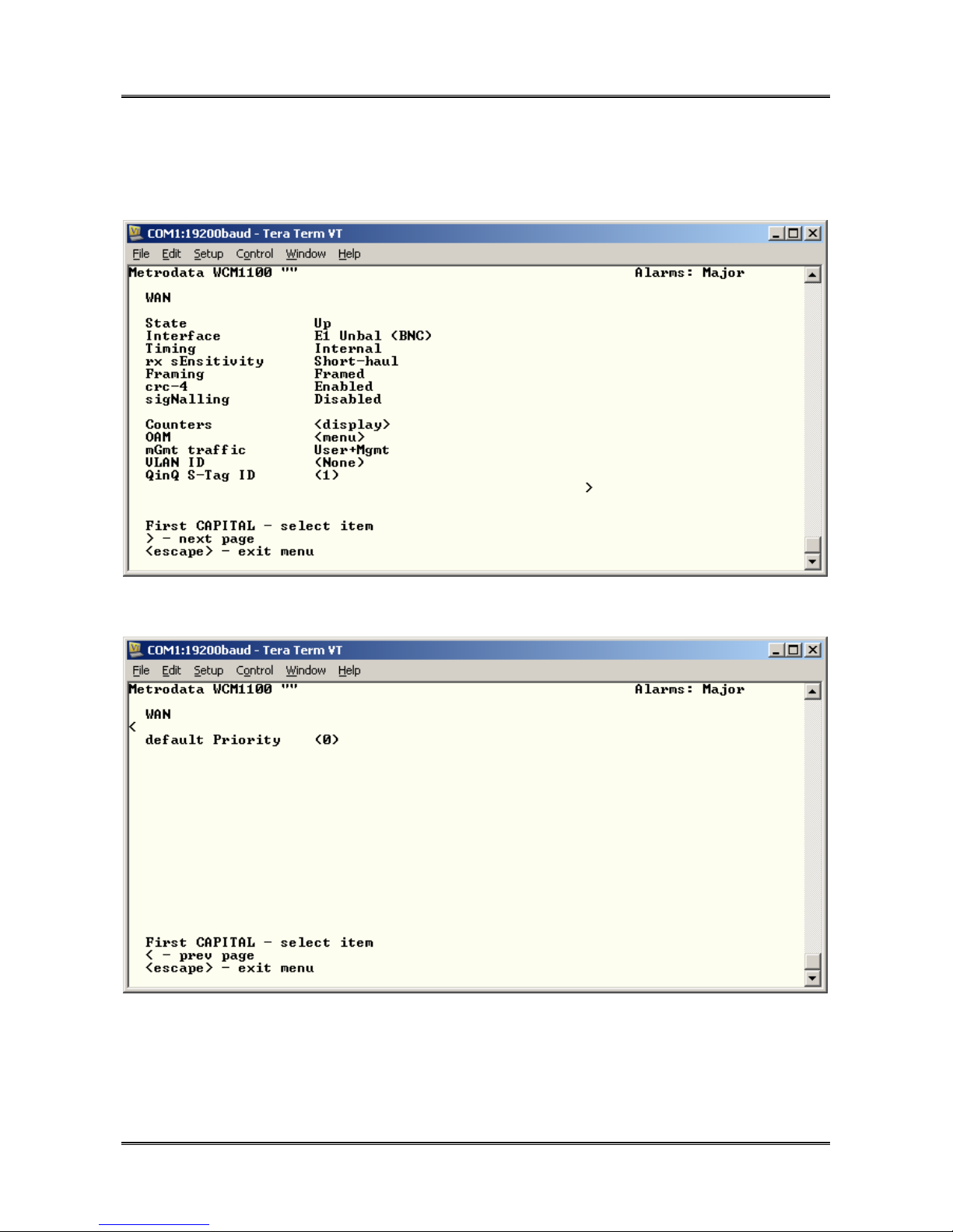
4.2.3 WCM1100 WAN Port
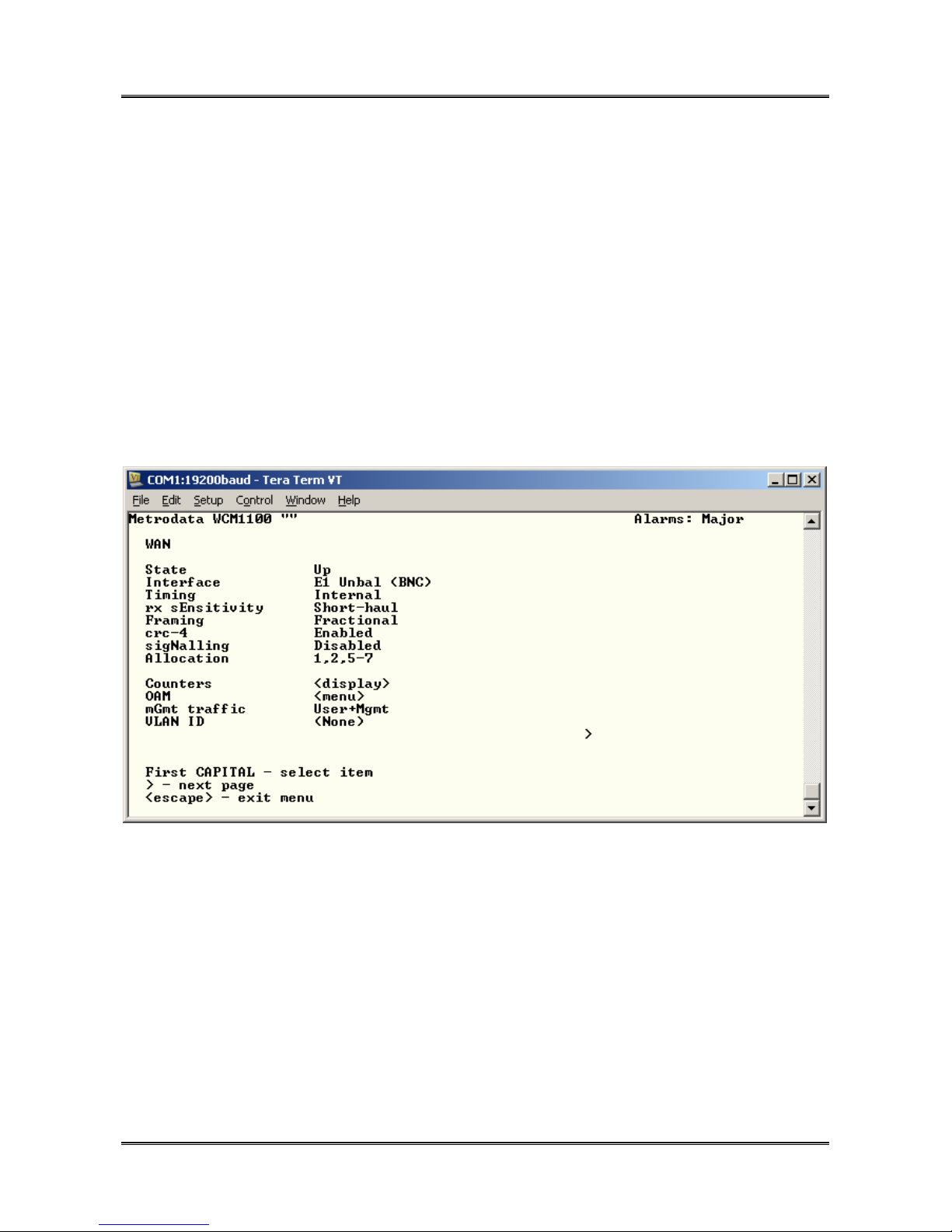
The WCM1100 WAN Port menu is as below:
46 of 75
and next page
The available options are as below:
76-02-082 Rev D
Page 47

METRODATA LTD WCM1100 / WCM3100 / WCM-Serial
47 of 75
Quick Start Guide
4.2.3.1 State
The state configuration defines the Administrative State of the WAN port. For normal
operation it must be set to UP.
In applications where the WAN link is not used, the state should be set to Down to disable
the alarm processing on the WAN port.
4.2.3.2 Interface
The E1 port physical interface may be selected as below:
Unbalanced (BNC) E1 port operates in 75ohm, unbalanced mode presented
on BNC connectors
Balanced (RJ45) E1 port operates in 120ohm, balanced mode presented on
the RJ45 connector.
4.2.3.3 Timing
The E1 port may be operated in either:
Internal E1 Transmit Timing derived from the internal oscillator
Loop E1 Transmit Timing derived from the E1 Receive Timing. Under loss
of signal conditions, the timing will fall back to the local oscillator.
4.2.3.4 RX Sensitivity
The E1 port supports both short and long haul modes of operation. The Rx Sensitivity
mode may be toggled between
Short Haul max cable loss 12 dB
Long Haul max cable loss 43 dB
76-02-082 Rev D
Page 48
METRODATA LTD WCM1100 / WCM3100 / WCM-Serial
48 of 75
Quick Start Guide
4.2.3.5 Framing
The WAN port may be configured to operate in the following modes
Unframed Clear channel, 2.048Mbps
Framed G.704 Framed, 1.984Mbps payload
Fractional G.704 Framed, Nx64
4.2.3.6 Allocation
When Fractional Framing mode is selected, this configuration item allows the required
timeslots to be configured.
The timeslot allocation may be contiguous or non contiguous and may be defined as
follows:
1,2,3 Select timeslot 1, 2 and 3
1-3 Select timeslot 1 to 3
1,2,5-7 Select timeslots 1, 2 and 5, 6 and 7.
76-02-082 Rev D
Page 49
METRODATA LTD WCM1100 / WCM3100 / WCM-Serial
49 of 75
Quick Start Guide
4.2.3.7 CRC-4
When operating in Framed or Fractional mode CRC-4 multiframe mode may be enabled or
disabled.
4.2.3.8 sigNalling
When operating in framed mode, the signaling option determines whether timeslot 16 is
available for payload. With Signalling Enabled timeslot 16 is not used for payload giving a
link capacity of 1.920MBps rather than 1.984MBps.
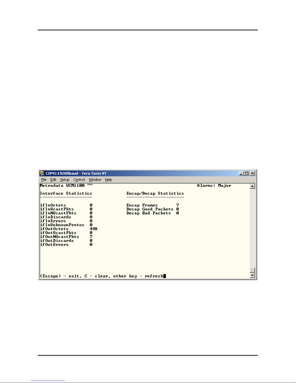
4.2.3.9 Counters
The counters option displays the MIB-2 statistics gathered for the WAN port.
Additionally, the WAN ports displays the statistics for the packet encapsulator. Since the
WAN port operates at a lower speed then the LAN ports, there may be traffic overload
leading to packet discards. The Interface Statistics contain the frames that enter/leave the
WAN port on the system side. The ifIn statistics correspond to the Encap Frames count
and thus if the combined “ifInUcastPkts” and “ifInNUcastPkts” counts are greater than the
Encap Frames, it is a sign that packets are being discarded due to WAN link overload.
76-02-082 Rev D
Page 50
METRODATA LTD WCM1100 / WCM3100 / WCM-Serial
50 of 75
Quick Start Guide
4.2.3.10 OAM
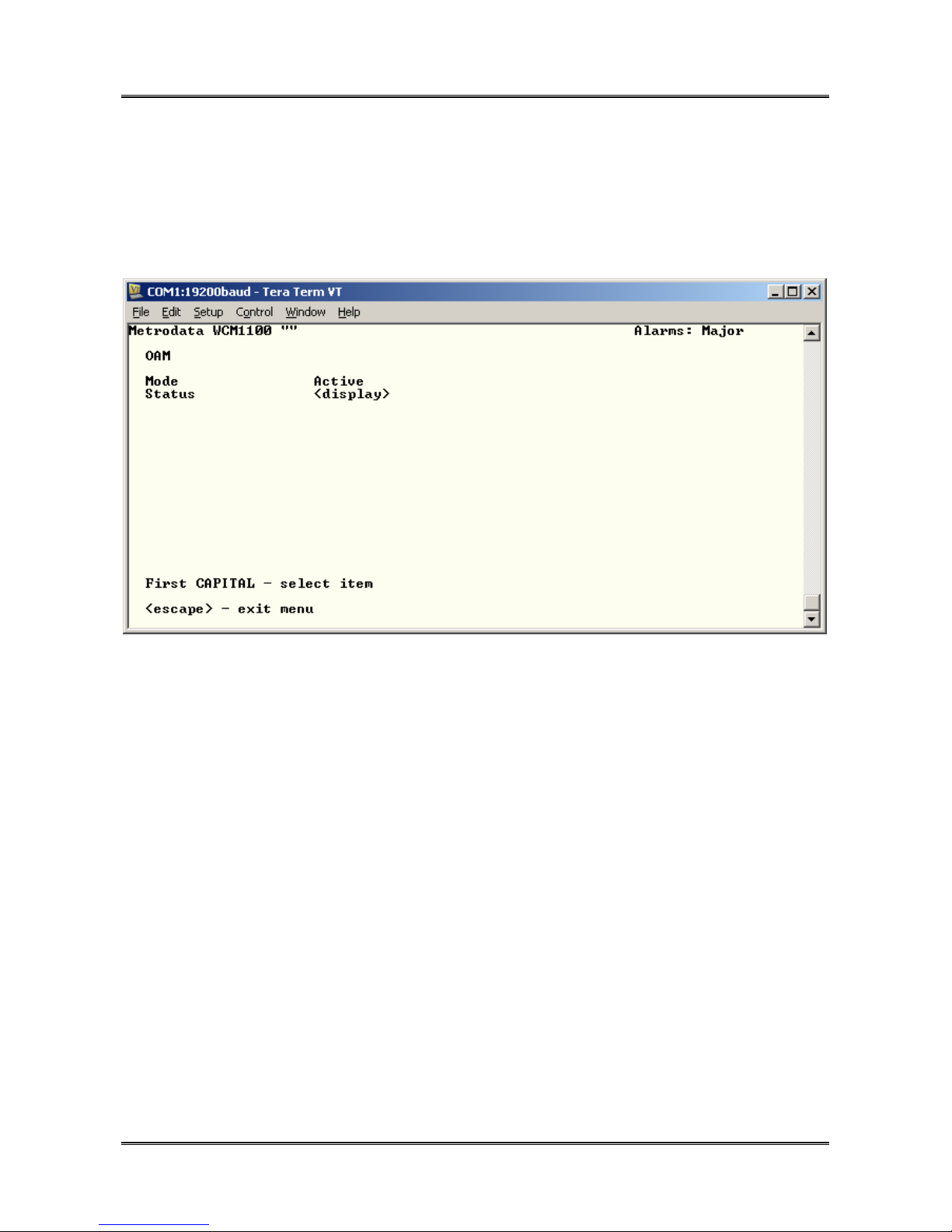
The WCM1100 WAN Port supports IEEE 802.3ah Link OAM which may be configured on
a per port basis:
4.2.3.10.1 OAM Mode
The port may be configured to be:
Disabled OAM packets not generated, and discarded
Active OAM status requests generated once per second
Passive OAM Status Updates will be generated in response to Status
Requests.
76-02-082 Rev D
Page 51
METRODATA LTD WCM1100 / WCM3100 / WCM-Serial
51 of 75
Quick Start Guide
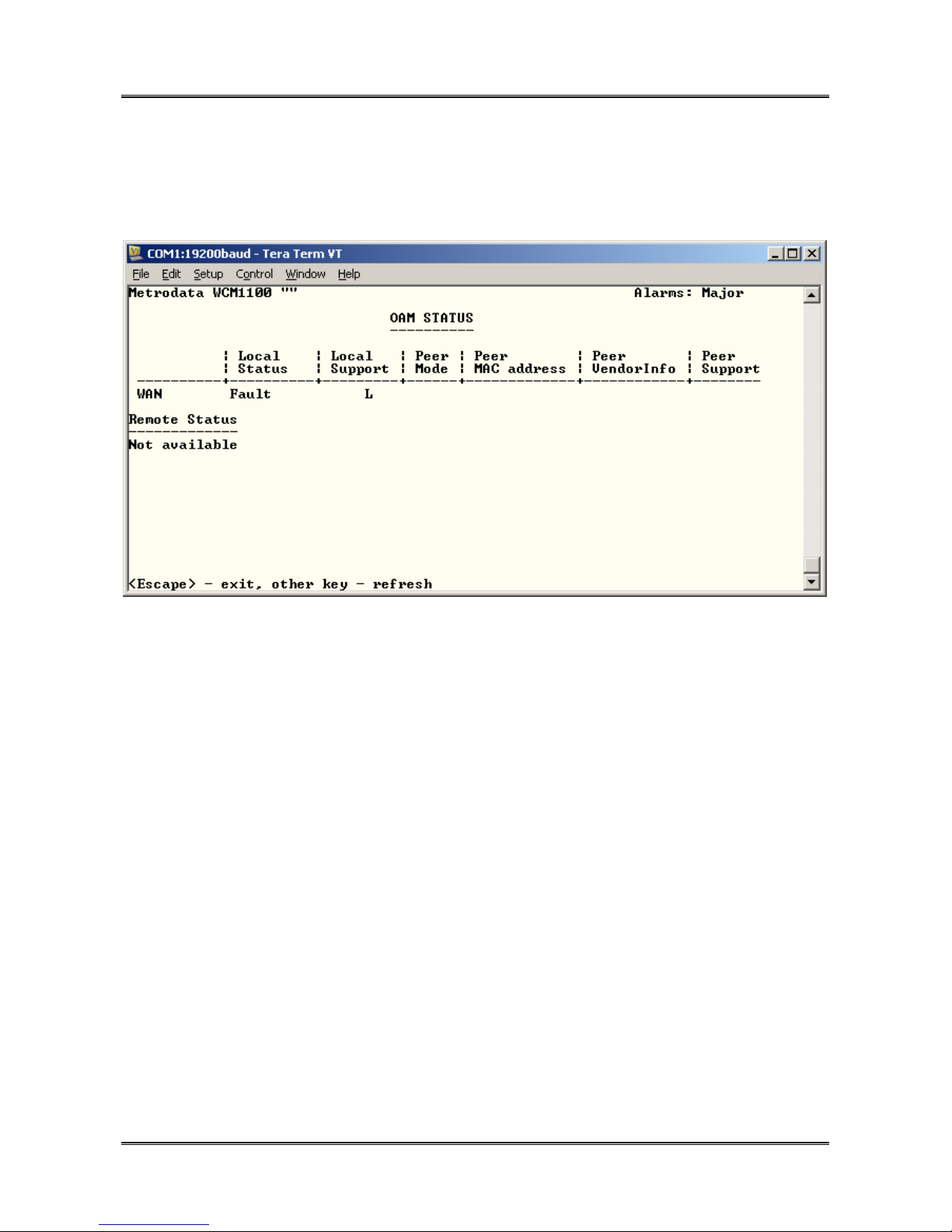
4.2.3.10.2 OAM Status
When two ports are running OAM, the status screen enables the user to determine the
status of the remote device.
Where the peer device is another Metrodata device, proprietary extensions to OAM are
used to report further peer status information.
4.2.3.11 mGmt Traffic
In order to provide traffic isolation this parameter defines what type of traffic passes over
this interface. The options are as below
User + Mgmt This port carries user and management traffic. Management frames
are switched to the processor, whilst user frames are switched to the
LAN ports.
User only This port only carries user traffic and ALL frames are switched to the
LAN ports with no access to the management processor
Mgmt only This port only carries Management Traffic and all frames are
forwarded to the management processor with no frames forwarded to
the LAN ports. This state MUST be avoided as it would prevent any
user data passing over the E1 interface.
76-02-082 Rev D
Page 52

METRODATA LTD WCM1100 / WCM3100 / WCM-Serial
52 of 75
Quick Start Guide
4.2.3.12 VLAN ID
If the Traffic Isolation mode is set to VLAN then the WAN port may be configured as either
ACCESS, or TRUNK.
A port is configured as an Access Port if it is assigned to a VLAN, ie given a VLAN ID
between 1 and 4095. All frames ingressing this port will have a VLAN Tag added, and on
egress will have the tag removed. This configuration item defines the VLAN ID which will
be added and may be in the range (1 to 4095 ). One or more ports may be assigned to the
same VLAN and packets will then only switch between those ports and trunk ports.
A port is configured as TRUNK, if the VLAN ID 0 or none is selected. In this case frames
ingress, or egress, with tags unchanged. A trunk is assumed to be a member of all VLANs
In normal operation, the WAN port will be assigned Trunk Status.
4.2.3.13 QinQ S-TAG ID
If the Traffic Isolation mode is set to QinQ then the WAN port may be assigned provider
mode Service Tag, S-TAG. and all frames ingressing this port will have the S-Tag added.
This configuration item defines the S-TAG ID which will be added and may be in the range
(1 to 4095 ). One or more ports may be assigned the same S-TAG and packets will then
only switch between those ports and the WAN interface.
In QinQ mode, ingress packets may be tagged or untagged and all will have a single STAG stripped before egress.
4.2.3.14 default Priority
When the traffic isolation mode is VLAN, this is the priority value that is added with the
VLAN ID during ingress at an Access Port. In QinQ mode, untagged packets are given
this default priority, whilst tagged packets promote the C-TAG priority to the S-TAG
priority.
76-02-082 Rev D
Page 53
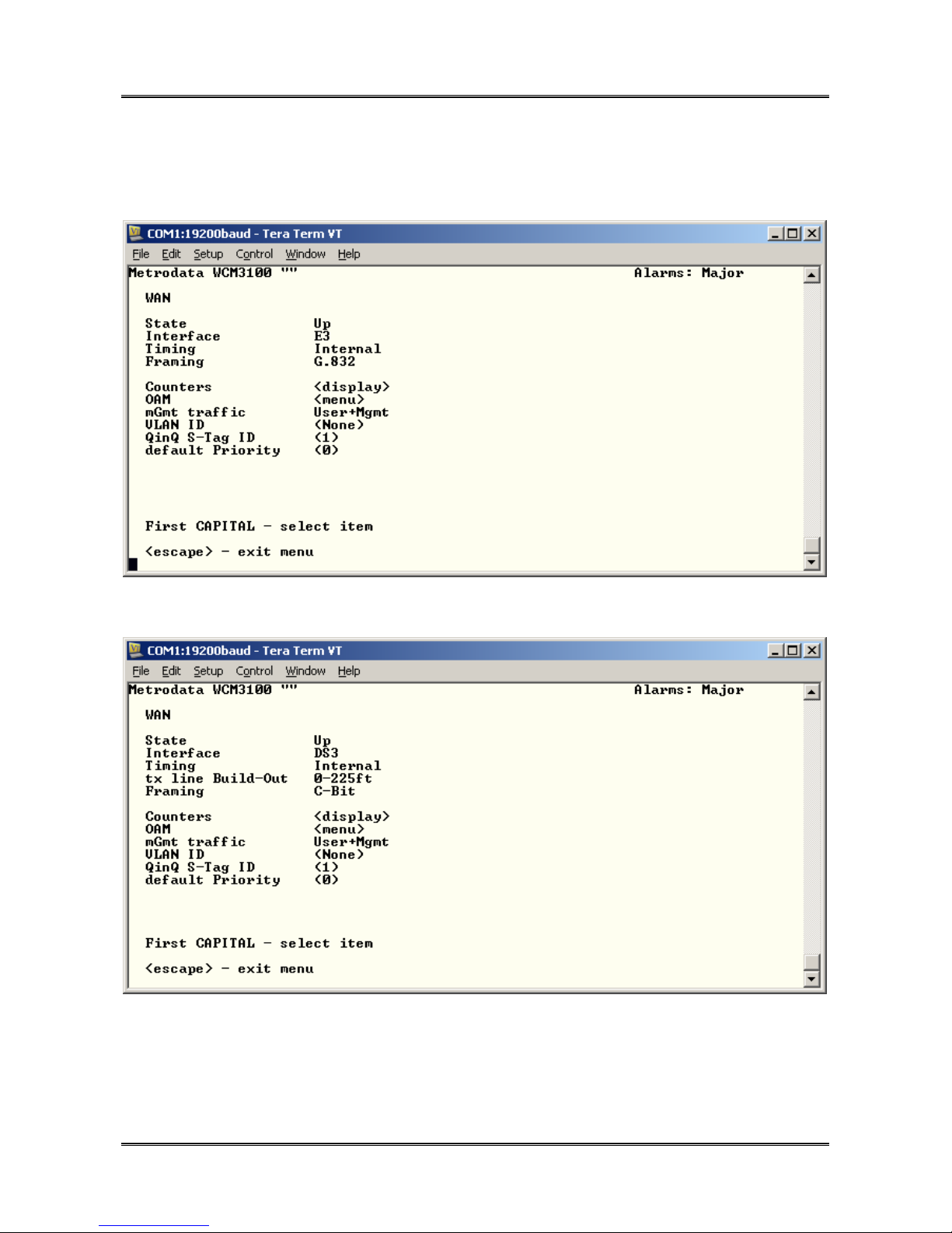
METRODATA LTD WCM1100 / WCM3100 / WCM-Serial
Quick Start Guide
4.2.4 WCM3100 WAN Port
The WCM3100 WAN Port menu is as below:
53 of 75
and when DS-3 is selected
The available options are as below:
76-02-082 Rev D
Page 54

METRODATA LTD WCM1100 / WCM3100 / WCM-Serial
54 of 75
Quick Start Guide
4.2.4.1 State
The state configuration defines the Administrative State of the WAN port. For normal
operation it must be set to UP.
In applications where the WAN link is not used, the state should be set to Down to disable
the alarm processing on the WAN port.
4.2.4.2 Interface
The WAN port physical interface may be selected as below:
E3 The WAN port operates in E3, G.703 mode at
34.368Mbps. The interface can operate in G.832 Framed
mode or clear channel, unframed mode.
DS-3 The WAN port operates in DS-3, G703 mode at
44.736Mbps. The interface can operate in C-Bit Framed
mode or clear channel, unframed mode.
4.2.4.3 Timing
The WAN port may be operated in either:
Internal Transmit Timing derived from the internal oscillator
Loop Transmit Timing derived from the Receive Timing. Under loss of
signal conditions, the timing will fall back to the local oscillator.
4.2.4.4 TX Line Build Out (DS-3 mode Only)
The DS-3 standard defines the wave shape at the far end of the cable and as such to
prevent overdrive of a short cable run, the transmitter power may be reduced.
The line build out configures the interface to drive cables of differing lengths as below:
0 – 225ft Set for Shorter cable runs
>225ft Set for longer cable runs upto 450ft.
76-02-082 Rev D
Page 55
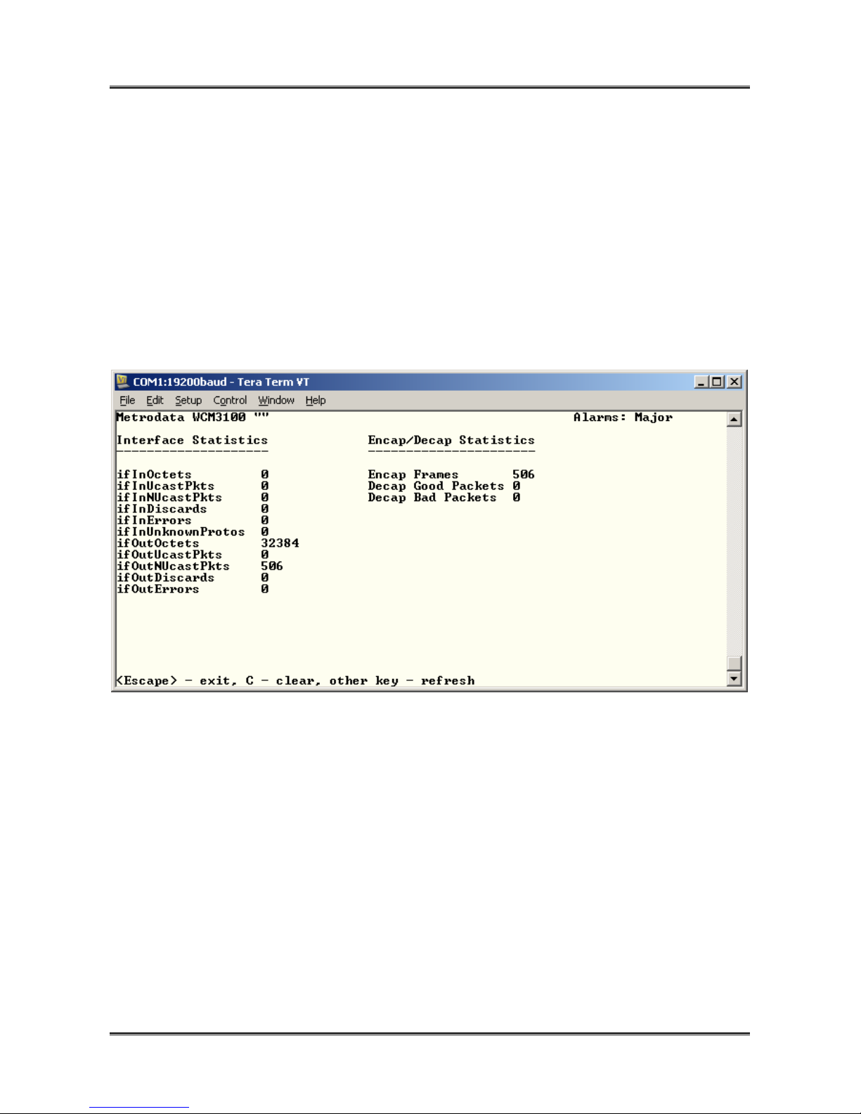
METRODATA LTD WCM1100 / WCM3100 / WCM-Serial
Quick Start Guide
4.2.4.5 Framing
The WAN port may be configured to operate in the following modes
Unframed Clear channel, E3 or DS-3
Framed G.832 E3 / C-Bit DS-3
4.2.4.6 Counters
The counters option displays the MIB-2 statistics gathered for the WAN port.
55 of 75
Additionally, the WAN ports displays the statistics for the packet encapsulator. Since the
WAN port operates at a lower speed then the LAN ports, there may be traffic overload
leading to packet discards. The Interface Statistics contain the frames that enter/leave the
WAN port on the system side. The ifIn statistics correspond to the Encap Frames count
and thus if the combined “ifInUcastPkts” and “ifInNUcastPkts” counts are greater than the
Encap Frames, it is a sign that packets are being discarded due to WAN link overload.
76-02-082 Rev D
Page 56
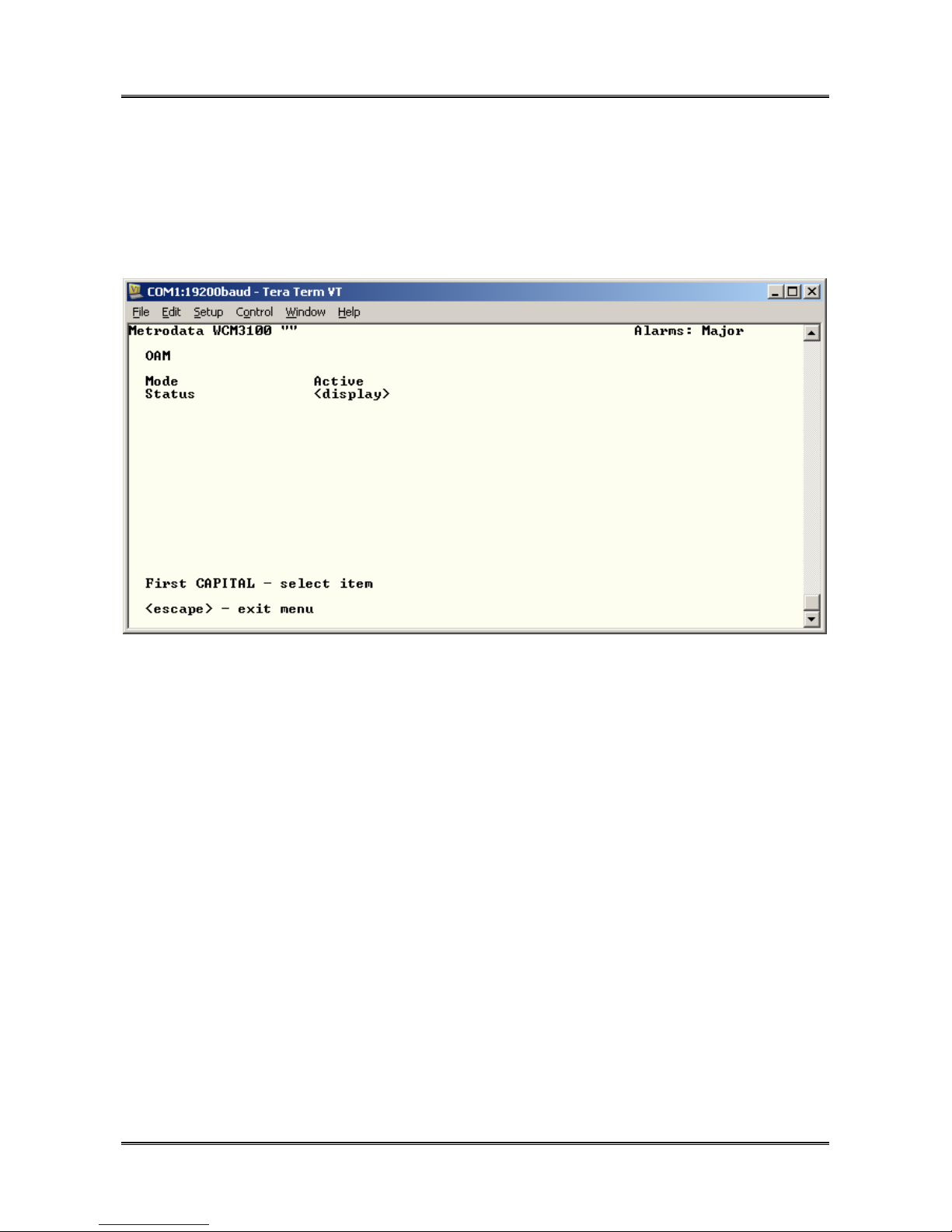
METRODATA LTD WCM1100 / WCM3100 / WCM-Serial
56 of 75
Quick Start Guide
4.2.4.7 OAM
The WCM3100 WAN Port supports IEEE 802.3ah Link OAM which may be configured on
a per port basis:
4.2.4.7.1 OAM Mode
The port may be configured to be:
Disabled OAM packets not generated, and discarded
Active OAM status requests generated once per second
Passive OAM Status Updates will be generated in response to Status
Requests.
76-02-082 Rev D
Page 57
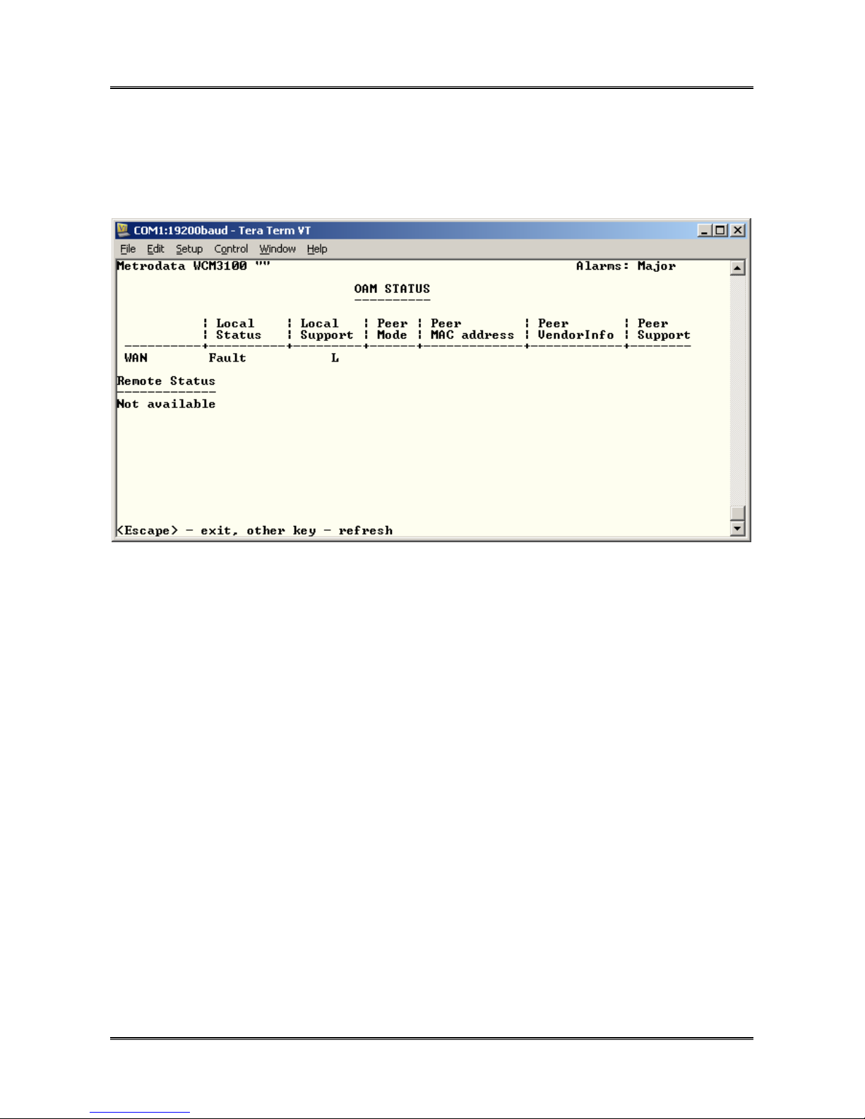
METRODATA LTD WCM1100 / WCM3100 / WCM-Serial
57 of 75
Quick Start Guide
4.2.4.7.2 OAM Status
When two ports are running OAM, the status screen enables the user to determine the
status of the remote device.
Where the peer device is another Metrodata device, proprietary extensions to OAM are
used to report further peer status information.
4.2.4.8 mGmt Traffic
In order to provide traffic isolation this parameter defines what type of traffic passes over
this interface. The options are as below
User + Mgmt This port carries user and management traffic. Management frames
are switched to the processor, whilst user frames are switched to the
LAN ports.
User only This port only carries user traffic and ALL frames are switched to the
LAN ports with no access to the management processor
Mgmt only This port only carries Management Traffic and all frames are
forwarded to the management processor with no frames forwarded to
the LAN ports. This state MUST be avoided as it would prevent any
user data passing over the E1 interface.
76-02-082 Rev D
Page 58

METRODATA LTD WCM1100 / WCM3100 / WCM-Serial
58 of 75
Quick Start Guide
4.2.4.9 VLAN ID
If the Traffic Isolation mode is set to VLAN then the WAN port may be configured as either
ACCESS, or TRUNK.
A port is configured as an Access Port if it is assigned to a VLAN, ie given a VLAN ID
between 1 and 4095. All frames ingressing this port will have a VLAN Tag added, and on
egress will have the tag removed. This configuration item defines the VLAN ID which will
be added and may be in the range (1 to 4095 ). One or more ports may be assigned to the
same VLAN and packets will then only switch between those ports and trunk ports.
A port is configured as TRUNK, if the VLAN ID 0 or none is selected. In this case frames
ingress, or egress, with tags unchanged. A trunk is assumed to be a member of all VLANs
In normal operation, the WAN port will be assigned Trunk Status.
4.2.4.10 QinQ S-TAG ID
If the Traffic Isolation mode is set to QinQ then the WAN port may be assigned provider
mode Service Tag, S-TAG. and all frames ingressing this port will have the S-Tag added.
This configuration item defines the S-TAG ID which will be added and may be in the range
(1 to 4095 ). One or more ports may be assigned the same S-TAG and packets will then
only switch between those ports and the WAN interface.
In QinQ mode, ingress packets may be tagged or untagged and all will have a single STAG stripped before egress.
4.2.4.11 default Priority
When the traffic isolation mode is VLAN, this is the priority value that is added with the
VLAN ID during ingress at an Access Port. In QinQ mode, untagged packets are given
this default priority, whilst tagged packets promote the C-TAG priority to the S-TAG
priority.
76-02-082 Rev D
Page 59
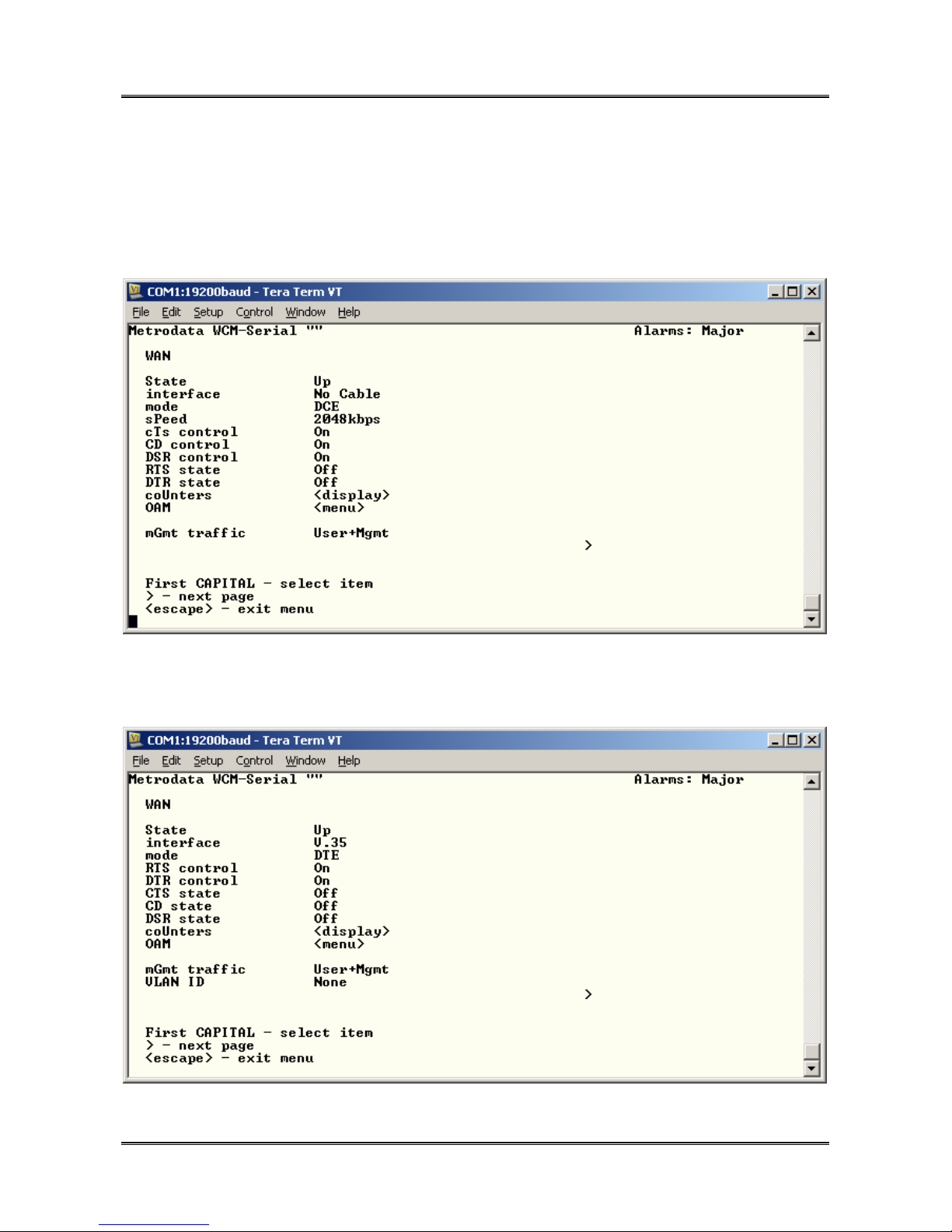
METRODATA LTD WCM1100 / WCM3100 / WCM-Serial
59 of 75
Quick Start Guide
4.2.5 WCM-Serial WAN Port Configuration
The main serial port menu varies depending upon which cable type is fitted. Below are the
options shown for no cable, V.35 and X.21
For no cable fitted:
With V.35 DTE ( CAB-V35-MT ) fitted:
76-02-082 Rev D
Page 60
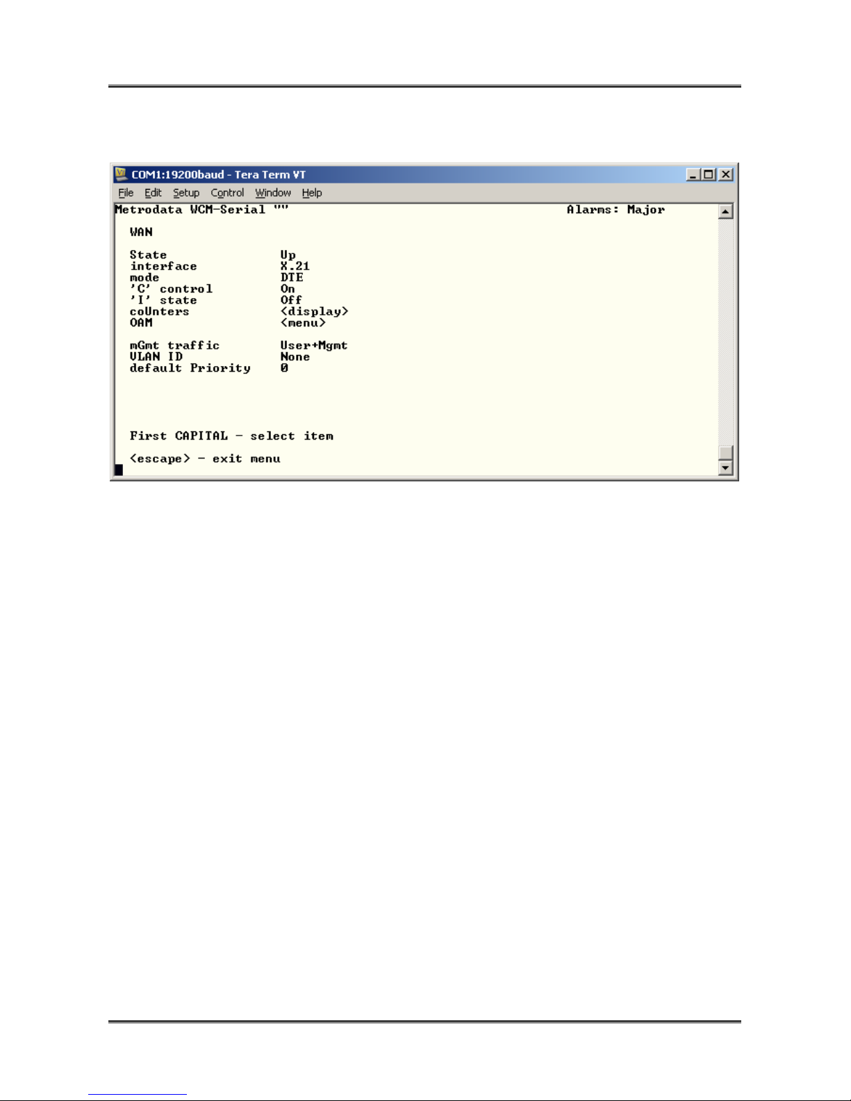
METRODATA LTD WCM1100 / WCM3100 / WCM-Serial
Quick Start Guide
With X.21 DTE ( CAB-X21-MT ) fitted
60 of 75
4.2.5.1 State
The state configuration defines the Administrative State of the WAN Serial port. For
normal operation it must be set to UP.
In applications where the WAN link is not used, the state should be set to Down to disable
the alarm processing on the WAN port.
4.2.5.2 Interface
This display item shows the type of cable that is fitted, and the electrical specification of
the serial interface. The following options are supported:
V.35 CAB-V35-MT CAB-V35-FC
X.21 CAB-X21-MT CAB-X21-FC
EIA-530 CAB-530-MT
V.36 CAB-V36-MT CAB-V36-FC
No Cable No cable fitted
76-02-082 Rev D
Page 61

METRODATA LTD WCM1100 / WCM3100 / WCM-Serial
61 of 75
Quick Start Guide
The serial cables all have identifiers in the HD60 connector to identify them and the multi
serial interface checks the cable type and configures itself accordingly.
4.2.5.3 Mode
The normal operating mode of the WCM-Serial is in DTE mode where timing is supplied
externally by the external NTU/Modem. For lab testing, a DCE mode is also available.
Options
DTE Selected by attached cable
DCE Selected by attached cable, and generates the link timing.
4.2.5.4 Controls
The serial interface supports several modem control outputs, the controls available
depends upon the interface type.
The option for each control is
ON Always ON, normal operation
OFF Always off
LOOP Looped to incoming control
4.2.5.5 State
These display items show the state of the incoming modem controls.
76-02-082 Rev D
Page 62
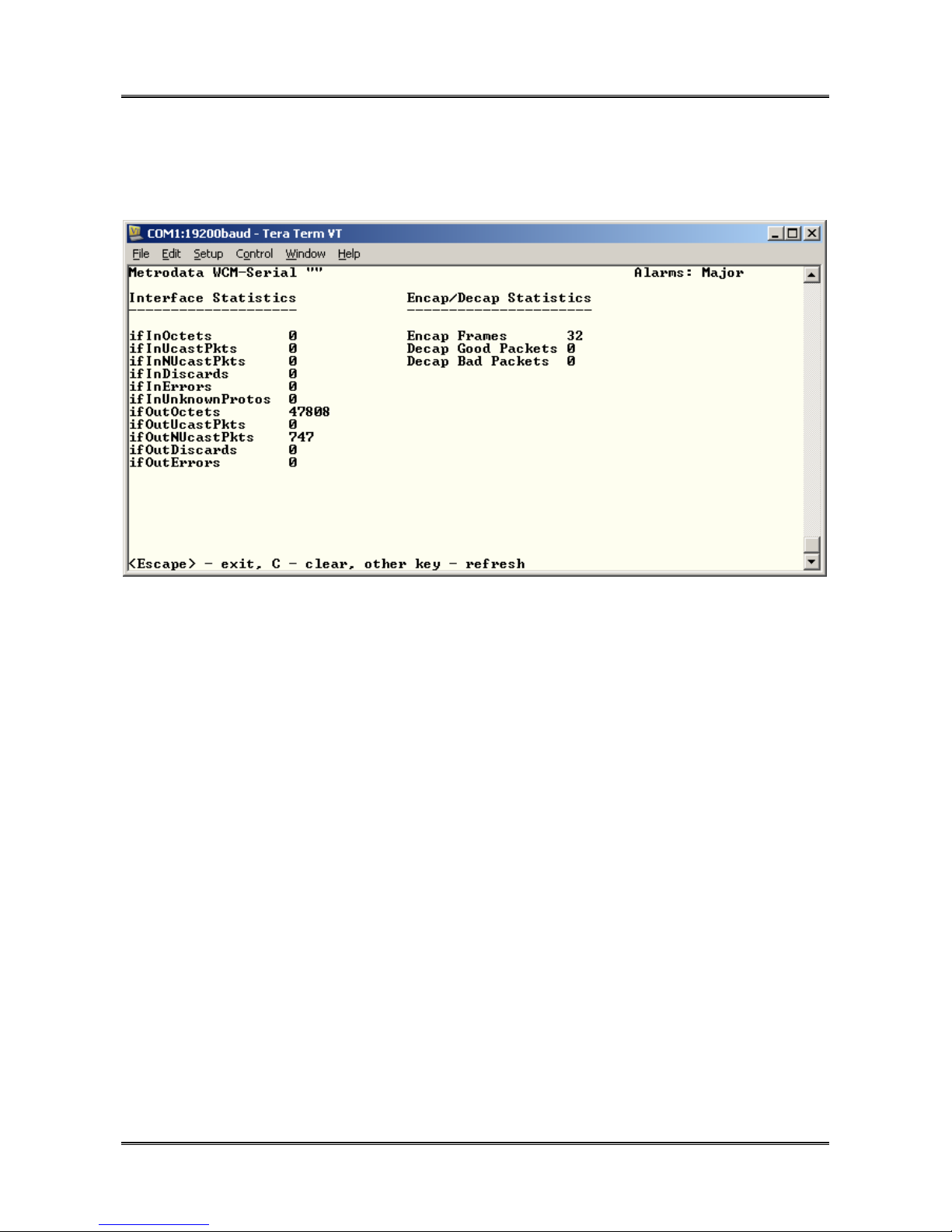
METRODATA LTD WCM1100 / WCM3100 / WCM-Serial
Quick Start Guide
4.2.5.6 Counters
The counters option displays the MIB-2 statistics gathered for the WAN port.
62 of 75
Additionally, the WAN ports displays the statistics for the packet encapsulator. Since the
WAN port operates at a lower speed then the LAN ports, there may be traffic overload
leading to packet discards. The Interface Statistics contain the frames that enter/leave the
WAN port on the system side. The ifIn statistics correspond to the Encap Frames count
and thus if the combined “ifInUcastPkts” and “ifInNUcastPkts” counts are greater than the
Encap Frames, it is a sign that packets are being discarded due to WAN link overload.
76-02-082 Rev D
Page 63
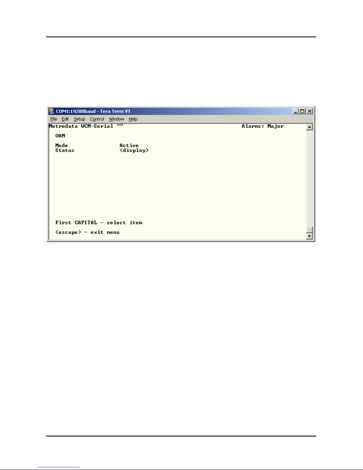
METRODATA LTD WCM1100 / WCM3100 / WCM-Serial
63 of 75
Quick Start Guide
4.2.5.7 OAM
The WCM-Serial WAN Port supports IEEE 802.3ah Link OAM which may be configured on
a per port basis:
4.2.5.7.1 OAM Mode
The port may be configured to be:
Disabled OAM packets not generated, and discarded
Active OAM status requests generated once per second
Passive OAM Status Updates will be generated in response to Status
Requests.
76-02-082 Rev D
Page 64
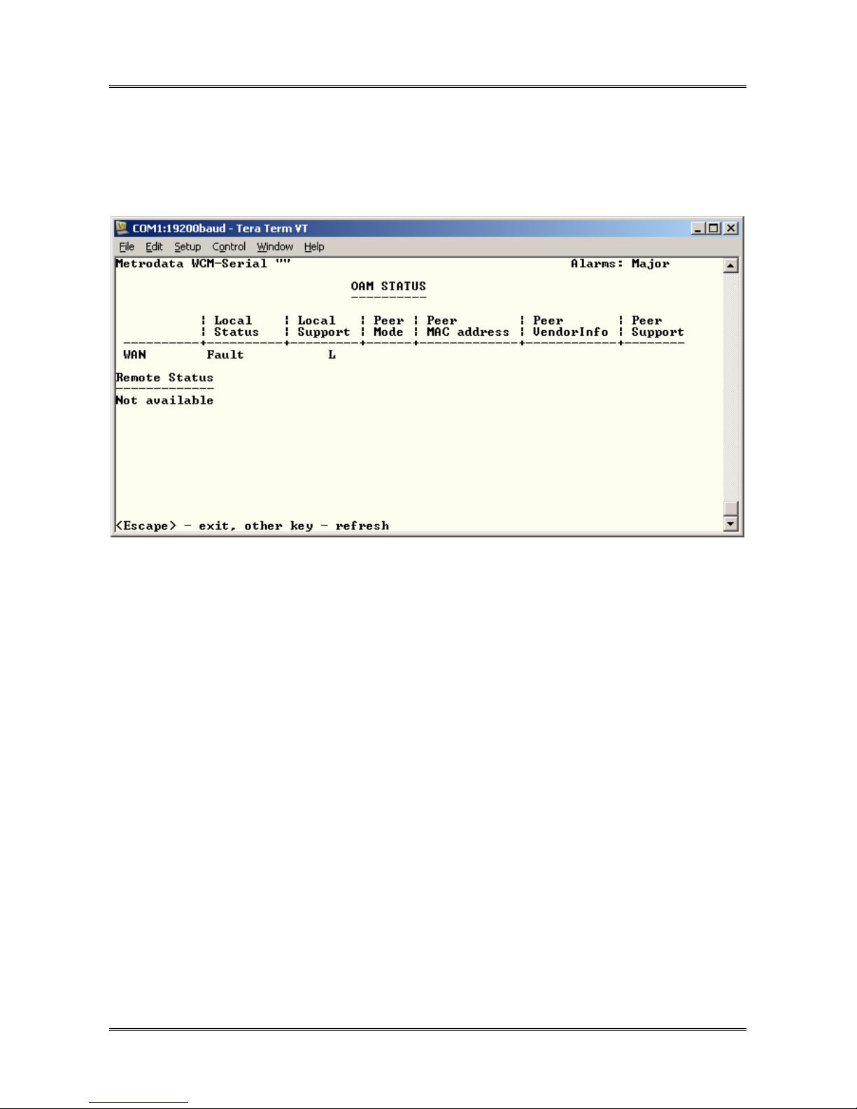
METRODATA LTD WCM1100 / WCM3100 / WCM-Serial
64 of 75
Quick Start Guide
4.2.5.7.2 OAM Status
When two ports are running OAM, the status screen enables the user to determine the
status of the remote device.
Where the peer device is another Metrodata device, proprietary extensions to OAM are
used to report further peer status information.
4.2.5.8 mGmt Traffic
In order to provide traffic isolation this parameter defines what type of traffic passes over
this interface. The options are as below
User + Mgmt This port carries user and management traffic. Management frames
are switched to the processor, whilst user frames are switched to the
LAN ports.
User only This port only carries user traffic and ALL frames are switched to the
LAN ports with no access to the management processor
Mgmt only This port only carries Management Traffic and all frames are
forwarded to the management processor with no frames forwarded to
the LAN ports. This state MUST be avoided as it would prevent any
user data passing over the WAN interface.
76-02-082 Rev D
Page 65

METRODATA LTD WCM1100 / WCM3100 / WCM-Serial
65 of 75
Quick Start Guide
4.2.5.9 VLAN ID
If the Traffic Isolation mode is set to VLAN then the WAN port may be configured as either
ACCESS, or TRUNK.
A port is configured as an Access Port if it is assigned to a VLAN, ie given a VLAN ID
between 1 and 4095. All frames ingressing this port will have a VLAN Tag added, and on
egress will have the tag removed. This configuration item defines the VLAN ID which will
be added and may be in the range (1 to 4095 ). One or more ports may be assigned to the
same VLAN and packets will then only switch between those ports and trunk ports.
A port is configured as TRUNK, if the VLAN ID 0 or none is selected. In this case frames
ingress, or egress, with tags unchanged. A trunk is assumed to be a member of all VLANs
In normal operation, the WAN port will be assigned Trunk Status.
4.2.5.10 QinQ S-TAG ID
If the Traffic Isolation mode is set to QinQ then the WAN port may be assigned provider
mode Service Tag, S-TAG. and all frames ingressing this port will have the S-Tag added.
This configuration item defines the S-TAG ID which will be added and may be in the range
(1 to 4095 ). One or more ports may be assigned the same S-TAG and packets will then
only switch between those ports and the WAN interface.
In QinQ mode, ingress packets may be tagged or untagged and all will have a single STAG stripped before egress.
4.2.5.11 default Priority
When the traffic isolation mode is VLAN, this is the priority value that is added with the
VLAN ID during ingress at an Access Port. In QinQ mode, untagged packets are given
this default priority, whilst tagged packets promote the C-TAG priority to the S-TAG
priority.
76-02-082 Rev D
Page 66

METRODATA LTD WCM1100 / WCM3100 / WCM-Serial
66 of 75
Quick Start Guide
4.2.6 Encapsulation
This menu allows the configuration of the packet encapsulation mode for transporting
packets across the WAN port.
Metrodata WCM "" Alarms: Major
ENCAPSULATION
Encapsulation HDLC
HDLC FCS 16-bit
strip MAC FCS Yes
Flow control Disabled
maX frame size 2048
Priority Table <menu>
First CAPITAL - select item
<escape> - exit menu
4.2.6.1 Encapsulation
The WCM V7.14 product range supports bit synchronous HDLC encapsulation for
unframed, or framed interfaces, or alternatively X.86 LAPS or GFP byte synchronous
modes for Framed interfaces.
4.2.6.1.1 HDLC
HDLC mode is the only option supported on the WCM-Serial, and on WCM1100/3100
when unframed interfaces are selected. HDLC uses flags (0x7E) and bit stuffing to
transmit packets over the WAN interface. When operating in HDLC mode, there are
several parameters which can be changed
4.2.6.1.1.1 HDLC FCS
When a packet is encapsulated a frame check sequence is added to the end of the packet
to enable transmission error detection. The options here are
16 bit A 16 bit FCS is calculated and added to the packet
32 bit A 32 bit FCS is calculated and added to the packet
76-02-082 Rev D
Page 67

METRODATA LTD WCM1100 / WCM3100 / WCM-Serial
67 of 75
Quick Start Guide
Both ends of the link MUST match otherwise traffic will not flow, For operation with an
unmanaged WC product, or previous software version 16 bit mode must be used.
4.2.6.1.1.2 Strip MAC FCS
A LAN packet is protected by a 32 bit FCS. Since the encapsulator will add an HDLC FCS
it is possible to save bandwidth by removing the Ethernet FCS and recalculate at the far
end.
Both ends of the link MUST match otherwise traffic will not flow, For operation with an
unmanaged WC product, or previous software version MAC FCS Stripping mode must be
used.
4.2.6.1.1.3 Payload Scrambler
For security purposes and to ensure a good ones density an X^43 scrambler may be
applied
Both ends of the link MUST match otherwise traffic will not flow, For operation with an
unmanaged WC product, or previous software version the payload scrambling must be
disabled
4.2.6.1.2 X.86
The WCM offers X.86 LAPS encapsulation when used on a framed, byte synchronous
interface. X.86 uses flags to delimit and pad, and appends a four byte header to the
packet along with a 32 bit FCS. Additional options are:
4.2.6.1.2.1 Strip MAC FCS
A LAN packet is protected by a 32 bit FCS. Since the encapsulator will add an HDLC FCS
it is possible to save bandwidth by removing the Ethernet FCS and recalculate at the far
end.
Both ends of the link MUST match otherwise traffic will not flow.
4.2.6.1.2.2 Payload Scrambler
For security purposes and to ensure a good ones density an X^43 scrambler may be
applied
Both ends of the link MUST match otherwise traffic will not flow.
4.2.6.1.2.3 VCAT
When a multiframe mode, eg CRC4 or G.832 are used then the additional option VCAT is
available. VCAT support enables the VCAT overhead byte to be added to allow
compatibility with other devices running VCAT.
76-02-082 Rev D
Page 68

METRODATA LTD WCM1100 / WCM3100 / WCM-Serial
68 of 75
Quick Start Guide
4.2.6.1.3 GFP
The WCM offers GFP encapsulation when used on a framed, byte synchronous interface.
GFP uses idle packets to delimit and pad, and appends a four byte header to the packet
along with a 32 bit FCS. Additional options are:
4.2.6.1.3.1 Strip MAC FCS
A LAN packet is protected by a 32 bit FCS. Since the encapsulator will add an HDLC FCS
it is possible to save bandwidth by removing the Ethernet FCS and recalculate at the far
end.
Both ends of the link MUST match otherwise traffic will not flow.
4.2.6.1.3.2 Payload Scrambler
For security purposes and to ensure a good ones density an X^43 scrambler may be
applied
Both ends of the link MUST match otherwise traffic will not flow.
4.2.6.1.3.3 VCAT
When a multiframe mode, eg CRC4 or G.832 are used then the additional option VCAT is
available. VCAT support enables the VCAT overhead byte to be added to allow
compatibility with other devices running VCAT.
4.2.6.2 Flow Control
The WCM may be configured to use IEEE 802.3x pause frame based flow control when
loss less operation is desired. If Flow control is to be enabled, all ports MUST be
configured for Auto Negotiation.
Enabling flow control disables the priority queue support and must be used with care since
flow control is not selective and may well block important traffic due to overload with low
priority traffic.
4.2.6.3 Max Frame Size
The WCM supports jumbo frames up to 10k bytes in size. The maximum frame size is
configurable to support either
1522 , 2048, 10k
76-02-082 Rev D
Page 69

METRODATA LTD WCM1100 / WCM3100 / WCM-Serial
69 of 75
Quick Start Guide
4.2.6.4 Priority Table
The WCM support priority queuing and may be configured to use the 802.1p priority tag, or
the IP DSCP flag as the priority indication.
The WCM supports 4 levels of priority queuing on the WAN port. The Priority table menu
allows the user to map the 8 levels of 802.1p, and 64 levels of DSCP to the four levels of
the WCM.
4.2.6.4.1 802.1p Mode
Metrodata WCM3100 "" Alarms: Major
PRIORITY TABLE
Priority Scheme 802.1p
1 High 6,7
2 Medium 4,5
3 Low 2,3
4 Best Effort 0,1
Restore Defaults
First CAPITAL - select item
<escape> - exit menu
4.2.6.4.2 IP DSCP Mode
Metrodata WCM3100 "" Alarms: Major
PRIORITY TABLE
Priority Scheme DSCP
1 High 40-63
2 Medium 24-39
3 Low 8-23
4 Best Effort 0-7
Restore Defaults
First CAPITAL - select item
<escape> - exit menu
76-02-082 Rev D
Page 70

METRODATA LTD WCM1100 / WCM3100 / WCM-Serial
70 of 75
Quick Start Guide
4.2.7 Traffic Isolation
The WCM contains a VLAN aware switch and will support Access and Trunk ports with
VLAN tags and Priorities being added on ingress to an Access port. The WCM also offers
QinQ S-Tag access ports to enable carriers to group customer traffic within a single group.
Metrodata WCM "" Alarms: Major
TRAFFIC ISOLATION
Isolation mode None
QinQ EtherType (9100)
First CAPITAL - select item
<escape> - exit menu
4.2.8 RSTP
The WCM supports Rapid Spanning Tree to prevent loops when back up or resilient
connections are made.
Metrodata WCM "" Alarms: Major
RSTP
Mode Enabled
Priority 8
maxAge 20
Hello time 2
Forward delay 15
Tx Hold 1
Version rstp
Status <display>
First CAPITAL - select item
<escape> - exit menu
76-02-082 Rev D
Page 71

METRODATA LTD WCM1100 / WCM3100 / WCM-Serial
71 of 75
Quick Start Guide
4.3 SNMP Management
The WCM needs to be configured with the details of the SNMP Network Management
Station before the unit will generate traps, or respond to SNMP polls.
The SNMP parameters are configured using the SNMP menu found under the
Management menu
Metrodata WCM "" Alarms: Major
SNMP
Read community public
Write community public
Trap community public
Managers <menu>
contact Person Metrodata Limited,Fortune House,
Crabtree Office Village,Eversl..
Node name
Location
Stats. <display>
trap Alarms <menu>
First CAPITAL - select item
<escape> - exit menu
4.3.1 Read/Write/Trap Community
To provide a level of security, communities are used to control access to the unit via
SNMP. Separate communities may be configured for Read/Write or Trap access.
4.3.2 Contact Person
The contact person is the SNMP MIB-2 system SysContact parameter, the default setting
is:
Metrodata Limited, Fortune House, Eversley Way, Egham, Surrey, TW20 8RY
The parameter may be up to 255 characters and should be configured to reflect the actual
installation requirements.
76-02-082 Rev D
Page 72

METRODATA LTD WCM1100 / WCM3100 / WCM-Serial
72 of 75
Quick Start Guide
4.3.3 Node Name
The node name is the SNMP MIB-2 system SysName parameter. By default this entry is
blank. The parameter may be up to 255 characters and should be configured to reflect the
actual installation requirements.
4.3.4 Location
The location is the SNMP MIB-2 system SysLocation parameter. By default this entry is
blank. The parameter may be up to 255 characters and should be configured to reflect the
actual installation requirements.
4.3.5 Managers
To enable access to the WCM using SNMP, specific manager addresses must be
configured. Once a Manager is assigned, the WCM will respond to polls and generate
traps for that manager. The WCM supports up to 10 configured Network Management
Stations.
The Add Manager Menu is as below:
Metrodata WCM "" Alarms: Major
ADD MANAGER
IP address 0.0.0.0
Access rights None
receives Traps No
Remove manager
First CAPITAL - select item
<escape> - exit menu
The IP address is the IP address of the assigned Network Management Station.
76-02-082 Rev D
Page 73

METRODATA LTD WCM1100 / WCM3100 / WCM-Serial
73 of 75
Quick Start Guide
The Access Rights supported are:
None No Access
Read Only Only SNMP GET access is allowed
Read-Write SNMP GET/SET access allowed
The Receive Traps parameter determines whether, under alarm conditions, Traps should
be sent to this Network Manager.
4.4 Saving the Configuration
Once the WCM has been configured, the configuration must be saved to the EEPROM to
provide non-volatile storage.
Metrodata WCM "" Alarms: Major
MAIN SET-UP
Global status <display>
alarm eXtension <menu>
Data port set-up <menu>
V.24 set-up <menu>
Management <menu>
System <menu>
Update EEPROM
Testing <menu>
Performance data <menu>
First CAPITAL - select item
<escape> - exit menu
To save the configuration, select “Update EEPROM” from the Main Setup Menu. At the
prompt, respond <Y> and the configuration will be saved.
If the configuration is changed and not saved to EEPROM, the configuration will be lost at
the next restart, whether a warm start or power cycle.
76-02-082 Rev D
Page 74

METRODATA LTD WCM1100 / WCM3100 / WCM-Serial
74 of 75
Quick Start Guide
5 TFTP SOFTWARE UPDATE
The WCM may be upgraded in the field using TFTP to upgrade the application software, or
to save or load the configuration.
In networks where firewalls and NAT addressing is used server mode must be used
otherwise either client or sever mode may be used.
5.1 TFTP Configuration
Under the management menu, select TFTP and enter the parameters as required:
5.1.1 Client Mode
Select client mode to display the menu as below:
Metrodata WCM "" Alarms: Major
TFTP
Mode Client
remote IP 0.0.0.0
Get new software <display>
get Config.
Put config.
First CAPITAL - select item
<escape> - exit menu
In client mode, an external server is required. Enter the IP address of the TFTP server
and then issue the Get new Software command.
Once the software has been downloaded it will prompt to check you wish to proceed with
the upgrade. Once the upgrade is completed, the WCM will restart.
76-02-082 Rev D
Page 75

METRODATA LTD WCM1100 / WCM3100 / WCM-Serial
75 of 75
Quick Start Guide
5.1.2 Server Mode
Select SERVER mode to display the menu as below:
Metrodata WCM "" Alarms: Major
TFTP
Mode Server
remote IP 0.0.0.0
Software file name software
Config. file name config
First CAPITAL - select item
<escape> - exit menu
In server mode, the transfer is initiated from an external client. If the file downloaded
matches that configured for Software or Config then they will be used to upgrade the
software or configuration.
To use TFTP, the IP address of the remote server must be entered.
For security reasons, it is recommended to change the default settings for software and
config file names to prevent unauthorised updates.
To initiate a TFTP transfer from a windows PC, select a DOS window and then type the
command
tftp –i “WCM IP Address” put “Source Filename” “Software File Name”
eg
tftp –i 192.168.0.1 put wcm1100.714 software
Which will load a file named “wcm1100.714” onto the WCM with IP address 192.168.0.1
and load as a file called “software”
76-02-082 Rev D
 Loading...