

Page 1
FCM9002 USER MANUAL
FCM9002 User Manual
Version 8.27
DATE: 19th September 2013
DOCUMENT NO: 76-02-095
REVISION: B
PREPARED BY: Ian Banbrook
Metrodata Ltd
Fortune House, Crabtree Office Village
Eversley Way, Egham Surrey, TW20 8RY, UK
Tel +44 1 784 744700
Fax: +44 1 784 744730
E-Mail: [email protected]
76-02-095 Rev.B Page 1 of 145
Page 2

FCM9002 USER MANUAL
METRODATA LTD
No part of this publication may be reproduced, transmitted,
transcribed, stored in a retrieval system, or translated into any
language or computer language, in any form or by any means,
electronic, mechanical, magnetic, optical, chemical, manual or
otherwise, without the prior written permission of
Metrodata Ltd, Fortune House,
Crabtree Office Village, Eversley Way,
Egham, Surrey, TW20 8RY, United Kingdom.
DISCLAIMER
Metrodata Ltd makes no representations or warranties with
respect to the contents hereof and specifically disclaims any
implied warranties or merchantability or fitness for any particular
purpose. Further, Metrodata Ltd reserves the right to revise this
publication and to make changes from time to time in the content
hereof without obligation of Metrodata Ltd to notify any person of
such revision or changes.
Copyright © 2013 by Metrodata Ltd,
All Rights Reserved
76-02-095 Rev.B Page 2 of 145
Page 3

FCM9002 USER MANUAL
Document History
8/7/2013 XA Document Created
14/8/13 A Document Updated to add support for
OpticalZonu OTDR SFP devices
19/9/13 B Document updated to show the LED
information, and also detail the initial
contact procedures
76-02-095 Rev.B Page 3 of 145
Page 4

FCM9002 USER MANUAL
1 INTRODUCTION.........................................................................................17
1.1 FCM9002 EDD .....................................................................................18
1.2 Safety ...................................................................................................18
1.3 Electro Magnetic Compatibility .............................................................18
1.3.1 EN55022 Statement......................................................................19
1.3.2 FCC Declaration............................................................................19
1.4 WEEE Directive....................................................................................19
1.5 RoHS Compliance................................................................................19
2 INSTALLATION...........................................................................................20
2.1 FCM9002 Rear Panel...........................................................................20
2.1.1 Mains Power..................................................................................20
2.1.2 DC Power......................................................................................20
2.2 Base Label and Bit Switches ................................................................21
2.2.1 WAN Port Configuration................................................................21
2.2.1.1 Switch 1, WAN Port................................................................21
2.2.1.2 Switch 2, Auto Negotiation .....................................................22
2.2.1.3 Switch 3/4, Speed ..................................................................22
2.2.1.4 Switch 5, Duplex.....................................................................22
2.2.2 Zero Touch Configuration Control .................................................23
2.2.2.1 Switch 7, Boot Location / (Autoboot) ......................................23
2.2.3 Switch 8, Master Boot Control / (Factory Default) .........................24
2.3 Rear Panel LED Indicators ...................................................................24
2.3.1 RJ45 Led Indicators.......................................................................24
2.3.2 SFP LED’s.....................................................................................25
76-02-095 Rev.B Page 4 of 145
Page 5

FCM9002 USER MANUAL
2.3.2.1 SFP Link (LK) LED.................................................................25
2.3.2.2 SFP Signal Detect (SD) LED..................................................25
2.3.3 Power (PWR) LED.........................................................................25
2.3.4 Unit Status (OK) LED ....................................................................26
2.4 Rackmounting.......................................................................................27
3 OPERATING MODES .................................................................................28
3.1 C-Tag Mode..........................................................................................28
3.2 S-Tag Mode..........................................................................................30
3.2.1 Pushing S-Tag onto Untagged Frame...........................................31
3.2.2 Pushing S-Tag onto Tagged Frame ..............................................32
4 CONFIGURATION.......................................................................................33
4.1 System Configuration ...........................................................................34
4.1.1 Setting the Time and Date.............................................................34
4.1.1.1 Time Zone..............................................................................35
4.1.1.2 NTP Server.............................................................................35
4.1.1.3 Sync Now...............................................................................35
4.1.2 Setting the Node Name.................................................................35
4.1.3 Provider ID ....................................................................................36
4.1.4 Access Control ..............................................................................36
4.1.4.1 Setting the Local Password....................................................36
4.1.4.1.1 Default Unit Password.........................................................37
4.1.4.1.2 Password Recovery ............................................................37
4.1.4.2 View User...............................................................................37
4.1.4.3 Super Me................................................................................37
4.1.4.4 TACACS+...............................................................................38
76-02-095 Rev.B Page 5 of 145
Page 6

FCM9002 USER MANUAL
4.1.4.4.1 Authentication .....................................................................39
4.1.4.4.2 Timeout...............................................................................39
4.1.4.4.3 Retries.................................................................................39
4.1.4.4.4 Server .................................................................................39
4.1.4.4.5 Encryption Key....................................................................39
4.1.5 Welcome Screen...........................................................................40
4.1.5.1 Display Screen.......................................................................41
4.1.6 Output Config ................................................................................41
4.1.7 Input Config...................................................................................42
4.1.8 Warm Start ....................................................................................42
4.1.9 Cold Start ......................................................................................42
4.1.10 Event Logs ....................................................................................43
4.1.10.1 System Event Log..................................................................44
4.1.10.2 Alarm Event Log.....................................................................44
4.1.10.3 Config Event Log....................................................................45
4.1.10.4 Full Event Log........................................................................45
4.1.11 Zero Touch Configuration..............................................................46
4.1.11.1 Zero Touch State....................................................................46
4.1.11.2 Software Upgrade Time .........................................................47
4.2 Management Entity...............................................................................48
4.2.1 Interface ........................................................................................48
4.2.1.1 STATE....................................................................................49
4.2.1.2 Physical Address....................................................................49
4.2.1.3 DHCP.....................................................................................49
4.2.1.4 IP Address..............................................................................49
76-02-095 Rev.B Page 6 of 145
Page 7

FCM9002 USER MANUAL
4.2.1.5 Net Mask................................................................................50
4.2.1.6 AT Table.................................................................................50
4.2.1.7 Stats.......................................................................................51
4.2.1.8 C-VLAN..................................................................................51
4.2.1.9 QinQ/S-VLAN.........................................................................51
4.2.1.10 802.1p Priority........................................................................51
4.2.1.11 Override Incoming..................................................................52
4.2.2 IP Configuration.............................................................................53
4.2.2.1 Default TTL.............................................................................53
4.2.2.2 DSCP Priority.........................................................................53
4.2.2.3 Routing Table.........................................................................54
4.2.2.4 Forwarding .............................................................................54
4.2.2.5 IP Statistics.............................................................................55
4.2.3 UDP...............................................................................................56
4.2.3.1 SNMP Ports............................................................................56
4.2.3.2 Statistics.................................................................................57
4.2.4 TCP...............................................................................................57
4.2.4.1 Statistics.................................................................................58
4.2.4.2 Connection Table...................................................................58
4.2.5 SNMP............................................................................................59
4.2.5.1 Communities ..........................................................................59
4.2.5.2 Managers ...............................................................................60
4.2.5.2.1 Dying Gasp Trap.................................................................61
4.2.5.3 Contact Person.......................................................................61
4.2.5.4 Node Name............................................................................61
76-02-095 Rev.B Page 7 of 145
Page 8

FCM9002 USER MANUAL
4.2.5.5 Location..................................................................................61
4.2.5.6 SNMP Statistics......................................................................62
4.2.5.7 Trap Alarms............................................................................63
4.2.6 Telnet/SSH....................................................................................64
4.2.6.1 Access Method.......................................................................64
4.2.6.2 Timeout ..................................................................................65
4.2.7 TFTP .............................................................................................66
4.2.7.1 Client Mode............................................................................66
4.2.7.1.1 Remote IP...........................................................................66
4.2.7.1.2 Get New Software...............................................................67
4.2.7.1.2.1 Failsafe Upgrade ..........................................................68
4.2.7.1.3 Boot Software Upgrade.......................................................68
4.2.7.1.4 Get Config...........................................................................69
4.2.7.1.5 Put Config ...........................................................................69
4.2.7.2 Server Mode...........................................................................69
4.2.7.2.1 Remote IP...........................................................................70
4.2.7.2.2 Software File Name.............................................................70
4.2.7.2.3 Config File Name ................................................................70
4.2.8 Ping...............................................................................................70
4.3 V.24 Set-up...........................................................................................71
4.3.1 Usage............................................................................................71
4.3.2 Console set-up ..............................................................................71
4.3.2.1 Terminal Type ........................................................................72
4.3.2.2 Via Modem.............................................................................72
4.3.2.3 Baud Rate ..............................................................................72
76-02-095 Rev.B Page 8 of 145
Page 9

FCM9002 USER MANUAL
4.3.2.4 Parity......................................................................................72
4.3.2.5 Data Bits.................................................................................73
4.3.2.6 Stop Bits.................................................................................73
4.3.2.7 Load New Config....................................................................73
4.4 Port Set Up Menu.................................................................................74
4.4.1 User LAN Port Configuration........................................................75
4.4.1.1 State.......................................................................................75
4.4.1.2 Link Status .............................................................................75
4.4.1.3 Speed.....................................................................................75
4.4.1.4 Duplex....................................................................................76
4.4.1.5 Auto Negotiation.....................................................................77
4.4.1.6 Negotiated..............................................................................77
4.4.1.7 MDI / MDIX.............................................................................77
4.4.1.8 OAM.......................................................................................79
4.4.1.8.1 OAM Mode..........................................................................79
4.4.1.8.2 OAM Status.........................................................................80
4.4.1.8.3 OAM Statistics.....................................................................80
4.4.1.8.4 OAM Events........................................................................81
4.4.1.9 Link Loss Forwarding .............................................................81
4.4.1.10 Tagging and Priority...............................................................81
4.4.1.10.1 Add C-Tag to.....................................................................82
4.4.1.10.2 C-Tag VID.........................................................................82
4.4.1.10.3 Priority Source...................................................................82
4.4.1.10.4 Default Priority...................................................................83
4.4.1.11 L2CP Management................................................................84
76-02-095 Rev.B Page 9 of 145
Page 10

FCM9002 USER MANUAL
4.4.1.11.1 Bridge Group.....................................................................85
4.4.1.11.1.1 OAM ...........................................................................85
4.4.1.11.1.2 STP/RSTP/MSTP.......................................................85
4.4.1.11.2 LACP / LACP Marker ........................................................86
4.4.1.11.2.1 OSSP..........................................................................86
4.4.1.11.2.2 LLDP...........................................................................86
4.4.1.11.2.3 Other Bridge...............................................................86
4.4.1.11.3 GARP Group.....................................................................87
4.4.1.11.3.1 GMRP.........................................................................87
4.4.1.11.3.2 GVRP .........................................................................87
4.4.1.11.3.3 Other GARP ...............................................................87
4.4.1.11.4 Cisco Group......................................................................88
4.4.1.11.5 Metrodata Group...............................................................88
4.4.1.11.5.1 Beacon .......................................................................88
4.4.1.11.5.2 L2CP Tunnel...............................................................88
4.4.1.11.5.3 Other Metrodata .........................................................89
4.4.1.11.6 Other Group......................................................................89
4.4.1.11.7 L2CP Flow.........................................................................89
4.4.1.12 Counters.................................................................................90
4.4.2 User SFP Port Configuration........................................................91
4.4.2.1 State.......................................................................................91
4.4.2.2 Link Status .............................................................................91
4.4.2.3 SFP Type ...............................................................................91
4.4.2.4 Speed.....................................................................................92
4.4.2.5 Duplex....................................................................................92
76-02-095 Rev.B Page 10 of 145
Page 11

FCM9002 USER MANUAL
4.4.2.6 Auto Negotiation.....................................................................92
4.4.2.7 Negotiated..............................................................................93
4.4.2.8 SFP Management ..................................................................93
4.4.2.8.1 Device Details.....................................................................94
4.4.2.8.2 Notifications.........................................................................94
4.4.2.8.3 OTDR SFP module Support................................................95
4.4.2.8.3.1 Fault Status ..................................................................96
4.4.2.8.3.2 Fault Distance...............................................................96
4.4.2.8.3.3 Fibre Length .................................................................96
4.4.2.8.3.4 Last Fault Start.............................................................97
4.4.2.8.3.5 Last Fault Cleared ........................................................97
4.4.2.8.3.6 Last Fault Distance.......................................................97
4.4.2.8.3.7 OTDR SFP Trap Support..............................................98
4.4.2.9 Tagging and Priority...............................................................98
4.4.2.10 L2CP Management................................................................98
4.4.2.11 OAM.......................................................................................99
4.4.2.12 Link Loss Forwarding.............................................................99
4.4.2.13 Counters.................................................................................99
4.4.3 WAN ( LAN/SFP ) Port Configuration..........................................100
4.4.3.1 State.....................................................................................101
4.4.3.2 Link Status ...........................................................................101
4.4.3.3 Speed...................................................................................101
4.4.3.3.1 Copper Interface Mode .....................................................101
4.4.3.3.2 Fibre Interface Selected....................................................102
4.4.3.4 Duplex..................................................................................102
76-02-095 Rev.B Page 11 of 145
Page 12

FCM9002 USER MANUAL
4.4.3.5 Auto Negotiation...................................................................103
4.4.3.6 SFP Management ................................................................103
4.4.3.7 Negotiated............................................................................103
4.4.3.8 MDI / MDIX...........................................................................104
4.4.3.9 Tagging and Priority.............................................................104
4.4.3.10 OAM.....................................................................................105
4.4.3.10.1 OAM Mode......................................................................105
4.4.3.10.2 OAM Status.....................................................................106
4.4.3.10.3 OAM Statistics.................................................................107
4.4.3.10.4 OAM Events....................................................................107
4.4.3.11 Counters...............................................................................108
4.5 Operational Modes .............................................................................109
4.5.1 WAN Port ....................................................................................109
4.5.2 VLAN Mode.................................................................................109
4.5.2.1 VLAN Mode – STag .............................................................110
4.5.2.2 VLAN Mode – CTag.............................................................111
4.5.3 Max Frame Size ..........................................................................111
4.5.4 Priority Translation.......................................................................111
4.5.5 CFM Domains .............................................................................111
4.5.5.1 Multicast Address.................................................................113
4.5.5.2 Edit a Domain.......................................................................113
4.5.5.2.1 Domain Name...................................................................113
4.5.5.2.2 Domain Name Format.......................................................114
4.5.5.2.3 Domain Level....................................................................114
4.5.5.2.4 Remove Domain ...............................................................115
76-02-095 Rev.B Page 12 of 145
Page 13

FCM9002 USER MANUAL
4.5.5.2.5 Domain Status Summary ..................................................115
4.5.5.2.6 Add Maintenance Domain.................................................115
4.6 Flow ( Services ).................................................................................116
4.6.1 List Flows ....................................................................................116
4.6.2 Add / View / Edit / Modify Flow....................................................117
4.6.2.1 Flow Number........................................................................118
4.6.2.2 Flow Name...........................................................................118
4.6.2.3 Flow State ............................................................................118
4.6.2.4 S-VLAN ID............................................................................118
4.6.2.5 User Port..............................................................................119
4.6.2.6 C-VLAN Allocation................................................................119
4.6.2.7 Include Untagged.................................................................120
4.6.2.8 Control C-Vlan......................................................................120
4.6.2.9 SLA/Policing Definition.........................................................120
4.6.2.9.1 CIR....................................................................................121
4.6.2.9.2 CBS...................................................................................121
4.6.2.9.3 EIR....................................................................................121
4.6.2.9.4 EBS...................................................................................121
4.6.2.9.5 Max Delay.........................................................................121
4.6.2.9.6 Max Delay Variation..........................................................122
4.6.2.9.7 Availability.........................................................................122
4.6.2.10 Flow CFM Configuration.......................................................123
4.6.2.10.1 MA, Maintenance Association Configuration...................123
4.6.2.10.1.1 MA Name..................................................................123
4.6.2.10.1.2 MA Name Format .....................................................124
76-02-095 Rev.B Page 13 of 145
Page 14

FCM9002 USER MANUAL
4.6.2.10.1.3 MA Domain...............................................................124
4.6.2.10.2 MEP, Maintenance End Point Configuration...................125
4.6.2.10.2.1 MEP ID.....................................................................125
4.6.2.10.2.2 MEP State ................................................................125
4.6.2.10.3 MEP CCM.......................................................................126
4.6.2.10.3.1 MEP DMM................................................................126
4.6.2.10.4 Counters .........................................................................127
4.6.2.10.5 Y.1731 Performance .......................................................127
4.6.2.10.6 Remove Flow..................................................................128
4.7 Circuit / Flow Tests.............................................................................129
4.7.1 Port Loops...................................................................................129
4.7.2 SAM Flow Testing, Service Assurance Module...........................130
4.7.2.1 SAM Mode ...........................................................................130
4.7.2.2 SAM Loopback.....................................................................131
4.7.2.2.1 WAN Port..........................................................................131
4.7.2.2.2 Well Known “Magic” Address............................................131
4.7.2.2.3 Device Specific Loopback Address...................................131
4.7.2.2.4 User Port(s).......................................................................132
4.7.2.2.5 Well Known “Magic” Address............................................132
4.7.2.2.6 Device Specific Loopback Address...................................132
4.7.2.3 SAM Test Regime................................................................133
4.7.2.4 Y.1564 Testing.....................................................................133
4.7.2.4.1 State..................................................................................133
4.7.2.4.2 View Results .....................................................................134
4.7.2.4.3 Profile................................................................................135
76-02-095 Rev.B Page 14 of 145
Page 15

FCM9002 USER MANUAL
4.7.2.4.4 Test Parameters................................................................135
4.7.2.4.4.1 Background Rate........................................................136
4.7.2.4.4.2 Go/No Go Test ...........................................................136
4.7.2.4.4.2.1 Go/No Go Test Time............................................136
4.7.2.4.4.3 CIR Test .....................................................................137
4.7.2.4.4.3.1 CIR Test Rate ......................................................137
4.7.2.4.4.3.2 CIR Test Time......................................................137
4.7.2.4.4.4 CBS Test....................................................................137
4.7.2.4.4.4.1 CBS Test Rate.....................................................137
4.7.2.4.4.4.2 CBS Test Burst Size ............................................138
4.7.2.4.4.4.3 CBS Test Time.....................................................138
4.7.2.4.5 CIR/EIR Test.....................................................................138
4.7.2.4.5.1.1 CIR/EIR Test CIR Rate........................................138
4.7.2.4.5.1.2 CIR/EIR Test EIR Rate ........................................138
4.7.2.4.5.1.3 CIR/EIR Test Time...............................................138
4.7.2.4.6 Flows.................................................................................139
4.7.2.5 Manual Mode Testing...........................................................140
4.7.2.5.1 Test Duration.....................................................................140
4.7.2.5.2 Test State..........................................................................140
4.7.2.5.3 Manual Setup....................................................................141
4.7.2.5.3.1 Flow............................................................................141
4.7.2.5.3.2 S-VLAN / C-VLAN ......................................................141
4.7.2.5.3.3 Local MAC..................................................................141
4.7.2.5.3.4 Remote MAC..............................................................142
4.7.2.5.3.5 Packet Size.................................................................142
76-02-095 Rev.B Page 15 of 145
Page 16

FCM9002 USER MANUAL
4.7.2.5.3.6 Packet Rate................................................................142
4.7.2.5.3.7 Bandwidth...................................................................142
4.7.2.5.3.8 Burst Size (Packets)...................................................142
4.7.2.5.3.9 Burst Size (CBS) ........................................................143
4.7.2.5.4 Test Summary...................................................................143
4.7.2.5.5 Clear Results.....................................................................143
APPENDIX 1 Initial Serial Connection to the FCM9002.................................144
APPENDIX 2 Initial LAN connection to FCM9002..........................................145
76-02-095 Rev.B Page 16 of 145
Page 17

FCM9002 USER MANUAL
1 INTRODUCTION
The Metrodata MetroConnect FCM9002 is a highly featured, cost effective
Ethernet Service Demarcation Device (EDD) which allows carriers, or aggregate
service providers to manage the service effectively.
The FCM9002 presents three physical ports, two copper ports on RJ45
connectors and a fibre port supporting an SFP module. All copper ports support
10/100/1000BaseT with auto negotiation and auto switching, whilst the Fibre port
supports both 1000BaseX and 100BaseFX SFP modules. Allocation of User and
Network ports is configurable, leading to the FCM9002 supporting the following
modes of operation:
Copper to Copper
Copper to Fibre ( + Copper )
Fibre to Copper ( + Copper )
The FCM9002 uses a flow based architecture with flows being supported with
either single tag push/pop operation for either tagged (QinQ) or untagged user
traffic streams. Both IEEE 802.1q VLAN C-Tags and IEEE 802.1ad Service
Tags are supported with a fully programmable S-Tag for maximum compatibility.
Extensive operational diagnostic information is available through the use of OAM,
both IEEE802.3 clause 57 Link OAM, and IEEE 802.1ag / Y.1731 Connectivity
and Fault Management OAM (CFM). Y.1731 also offers in service verification of
Service Level Agreements through the measurement of packet delays with sub
microsecond accuracy.
To assist Service Providers in provisioning customer circuits the FCM9002
includes a highly featured packet generator and packet monitor allowing for
RFC2544 and Y.1564 testing. The FCM9002 also includes a loopback facility
with MAC DA/SA swapping capability.
The FCM9002 offers a “Zero Touch Configuration” facility whereby a unit will
listen for a beacon and then automatically determine the management
connection and load a configuration file from a central server.
76-02-095 Rev.B Page 17 of 145
Page 18
FCM9002 USER MANUAL
1.1 FCM9002 EDD
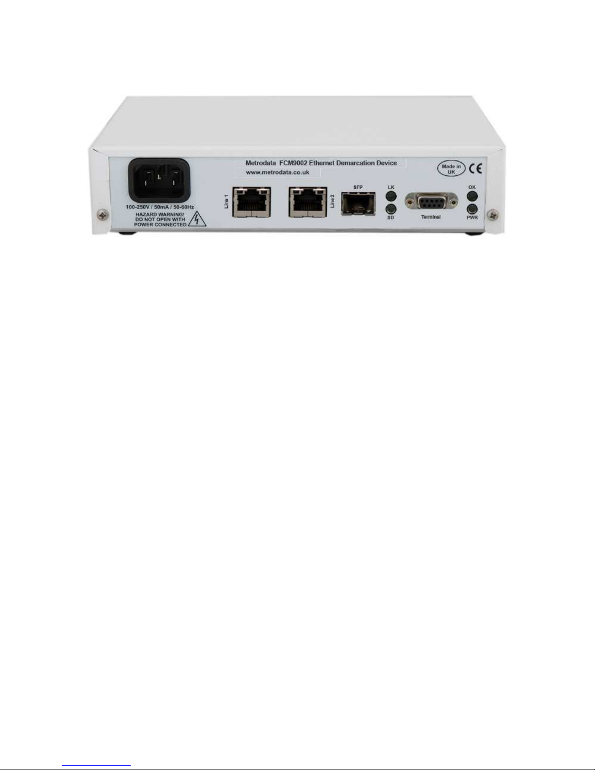
The FCM9002 is a compact unit as shown occupying half a shelf in a traditional
19inch rack. All connectors and LED status indicators are accessible from the
rear of the unit.
1.2 Safety
The FCM9002 must not be connected to cabling which would be required by
BS6701 to equipped with over voltage protection. The following ports on the
FCM9002 are designated SELV ( Safety Extra Low Voltage ) within the scope of
EN41003
Terminal Port 9 Way D-Type
LAN Port(s) RJ45 10/100/1000BaseT
SFP
These ports must only be connected to SELV ports on other equipment in
accordance with EN60950 clause 2.3
1.3 Electro Magnetic Compatibility
In order to ensure EMC compliance, all signal and data cables must be shielded
and use screened connector shells. The cable screens must be terminated to the
screened connector shell and not connected to any pins of the connector. Failure
to use the correct connectors may compromise EMC compliance.
76-02-095 Rev.B Page 18 of 145
Page 19

FCM9002 USER MANUAL
1.3.1 EN55022 Statement
The FCM9002 is a Class A product. In a domestic environment, this product may
cause radio interference, in which case the user will be required to take adequate
measures.
1.3.2 FCC Declaration
This equipment has been tested and found to comply with the limits of the Class
A digital device, pursuant to Part 15 of the FCC rules. These limits are designed
to provide reasonable protection against harmful interference when the
equipment is operated in a commercial environment. This equipment generates,
uses and can radiate radio frequency energy and, if not installed and used in
accordance with the Installation and Operation manual, may cause harmful
interference to the radio communications. Operation of this equipment in a
residential area is likely to cause harmful interference in which case the user will
be required to correct the interference at his own expense.
1.4 WEEE Directive
The FCM9002 is covered by Directive 2002/96/EC ( OJ:L37/24/2003 ) on Waste
Electrical and Electronic Equipment ( WEEE ) Units must therefore not be
disposed of in standard landfill.
1.5 RoHS Compliance
The FCM9002 is compliant with the EU RoHS Directive 2002/95/EC. The RoHS
directive bans the use of six hazardous materials in products placed on the
market after July 1st 2006. The six banned materials are Lead, Mercury,
Hexavalent Chromium, Polybrominated Biphenys, Polybrominated Diphenyl
Ethers and Cadmium.
The FCM9002 is manufactured using a lead free soldering process and as such
is fully RoHS 6/6 compliant.
76-02-095 Rev.B Page 19 of 145
Page 20
FCM9002 USER MANUAL
2 INSTALLATION
2.1 FCM9002 Rear Panel
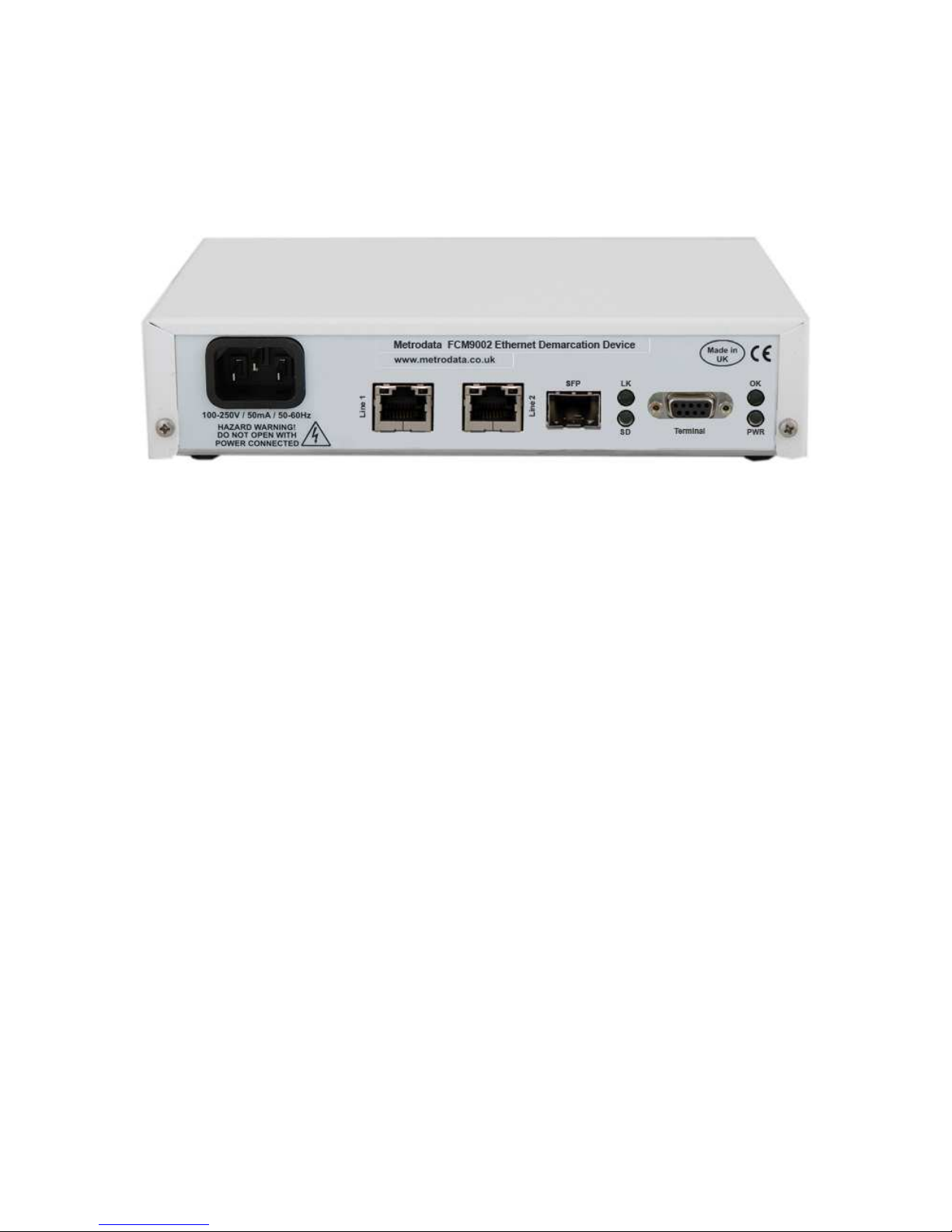
The FCM9002 is available with either AC Mains or DC power options.
2.1.1 Mains Power
The FCM9002 has an internal power supply and is supplied via an IEC mains
power socket. The FCM9002 operates over the wide range 100 to 250V AC and
draws less than 6 watts.
2.1.2 DC Power
The FCM9002 is available with an internal DC power supply with two variants
available,
DC -48V ( 36 to 72V DC )
DC 24V ( 7 to 36V DC )
DC powered units have an external earth stud which must be securely connected
to an earth connection to ensure EMC compliance.
76-02-095 Rev.B Page 20 of 145
Page 21
FCM9002 USER MANUAL
2.2 Base Label and Bit Switches
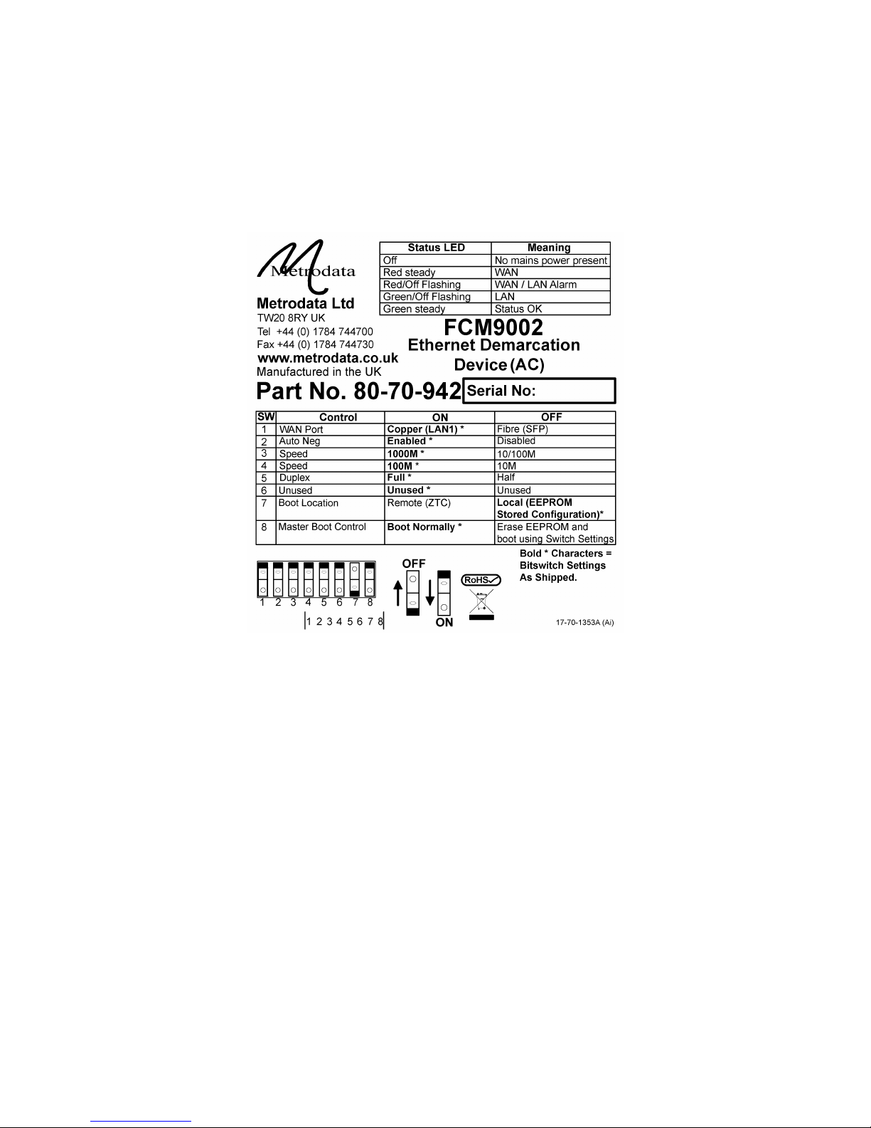
On the underside of the FCM9002 there are bit switches which may be used to
configure certain functions within the unit.
The bit switches are ONLY used to configure the default settings following a cold
start. A cold start may be triggered by setting switch 8 to the OFF position and
power cycling before returning SW8 to the normal ON position. Alternately, a
cold start may be requested from the User Interface.
2.2.1 WAN Port Configuration
Bit switches 1 to 5 are used to configure the default setting for the WAN Network
port of the device and are used on installation to ensure the FCM9002 physical
interface matches that of the network port it will connect to.
2.2.1.1 Switch 1, WAN Port
The WAN mode switch selects between the two physical interfaces for the WAN
port.
76-02-095 Rev.B Page 21 of 145
Page 22

FCM9002 USER MANUAL
ON Select LAN1 as the WAN copper interface, presenting a
10/100/1000BaseT interface on RJ45
OFF Select SFP as the WAN Fibre interface, presenting either
100Base-FX or 1000Base-X when an SFP module is
inserted.
2.2.1.2 Switch 2, Auto Negotiation
The Auto Negotiation switch controls whether the switch port is configured
automatically, or manually.
ON Auto Negotiation Enabled
OFF Manual controlled selection of speed and duplex
Note,
When the Fibre interface has been selected, Auto negation should be enabled for
1000BaseX, however MUST be disabled for 100Base-FX operation.
2.2.1.3 Switch 3/4, Speed
There are two bit switches used to select the speed control of the WAN port.
When auto negotiation is enabled, these switches control the options that are
advertised, whereas in manual mode, the speed switches actually select the
interface speed.
BitSw 3 BitSw4 Speed Auto Neg Advertise
ON Don’t Care 1000M 10/100/1000
OFF ON 100M 10/100
OFF OFF 10M 10
Note,
When the fibre interface is used, only 1000M and 100M options are valid.
2.2.1.4 Switch 5, Duplex
This switch controls the duplex mode of the port. When auto negotiation is
enabled this controls the advertised options, whilst in manual mode, it controls
the duplex mode.
76-02-095 Rev.B Page 22 of 145
Page 23

FCM9002 USER MANUAL
ON Full Duplex
OFF Half Duplex
Note,
When the fibre interface is selected, only Full Duplex modes are supported.
2.2.2 Zero Touch Configuration Control
There are two bit switches concerned with the setup of the unit to support the
zero touch configuration mode. When the FCM9002 uses the Zero Touch, Auto
Boot intialisation it will listen for a beacon on the selected WAN. The beacon
allows the FCM9002 to determine the correct tag values to use for a
management connection to DHCP/TFTP/SNMP servers.
2.2.2.1 Switch 7, Boot Location / (Autoboot)
This switch enables the autoboot, Zero Touch Configuration mode.
ON Auto Boot, ZTC enabled
OFF Disabled, boot from local configuration
When auto boot is enabled the FCM9002 will listen for a beacon on the WAN
port and then use the information gathered from this beacon to set up a
management channel connection to DHCP and TFTP servers, and also to an
SNMP manager.
76-02-095 Rev.B Page 23 of 145
Page 24
FCM9002 USER MANUAL
2.2.3 Switch 8, Master Boot Control / (Factory Default)
This bit switch will return the unit back to the factory default settings and will also
read the bit switches and configure the operating mode of the WAN port and
Auto Boot operation.
ON Normal Operation
OFF Return the unit to Factory Default on power up.
When a unit is returned to the factory default, the password will be returned to
the default, “FCM9002” and all IP and remote access configurations will be lost.
2.3 Rear Panel LED Indicators
The FCM9002 has eight LED indicators on the rear panel which show the port
and unit status.
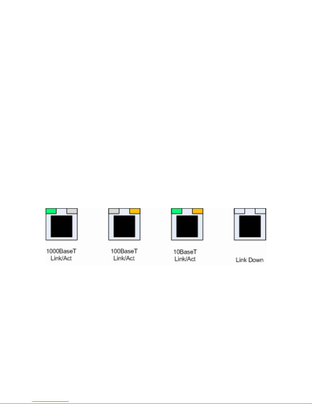
2.3.1 RJ45 Led Indicators
Each RJ45 connector has two LED’s, one green and one yellow and these are
combined to show the Link State, Link Activity and Link Speed as shown below:
If the LED(s) are ON, it indicates the Link is up, and the combination of Green
and Yellow LED’s indicates the speed.
If the LED(s) are Flashing, this indicates that the link is up, and activity is
detected on the link, ie frames are being received or transmitted.
All LED’s off indicates the link is down.
76-02-095 Rev.B Page 24 of 145
Page 25

FCM9002 USER MANUAL
2.3.2 SFP LED’s
The SFP interface has two status LED’s as described below
2.3.2.1 SFP Link (LK) LED
This Green LED indicates the state of the link.
OFF Link Down
ON Link UP
FLASH Link Up and Activity Detected
2.3.2.2 SFP Signal Detect (SD) LED
This bicolour LED indicates the status of the optical connection and has the
following options:
OFF No SFP Fitted
RED SFP Fittted, but no signal detected
GREEN Optical Signal Detected
Note, the initial model of FCM9002 using the Rev.XA PCB does not support the
RED LED, such that both Loss of Signal, and Not Fitted are shown by the LED
being OFF.
2.3.3 Power (PWR) LED
The Power LED is GREEN ON to indicate that the unit is powered up.
76-02-095 Rev.B Page 25 of 145
Page 26

FCM9002 USER MANUAL
2.3.4 Unit Status (OK) LED
The OK LED is a bicolour LED with the following states
OFF Unit not powered up
RED ON The selected WAN port has alarms
RED FLASH Both the selected WAN and User Ports have alarms
GREEN FLASH The User ports have alarms
GREEN ON No Alarms present.
The OK LED, gives an indication of the status of the device, and if it is not
displaying GREEN ON, ie normal operation, the user should view the Global
Status Screen on the user interface to determine the current alarm state.
It is advisable to change the state of unused ports to down as this will prevent
them from generating alarms which will show on the OK LED.
76-02-095 Rev.B Page 26 of 145
Page 27
FCM9002 USER MANUAL
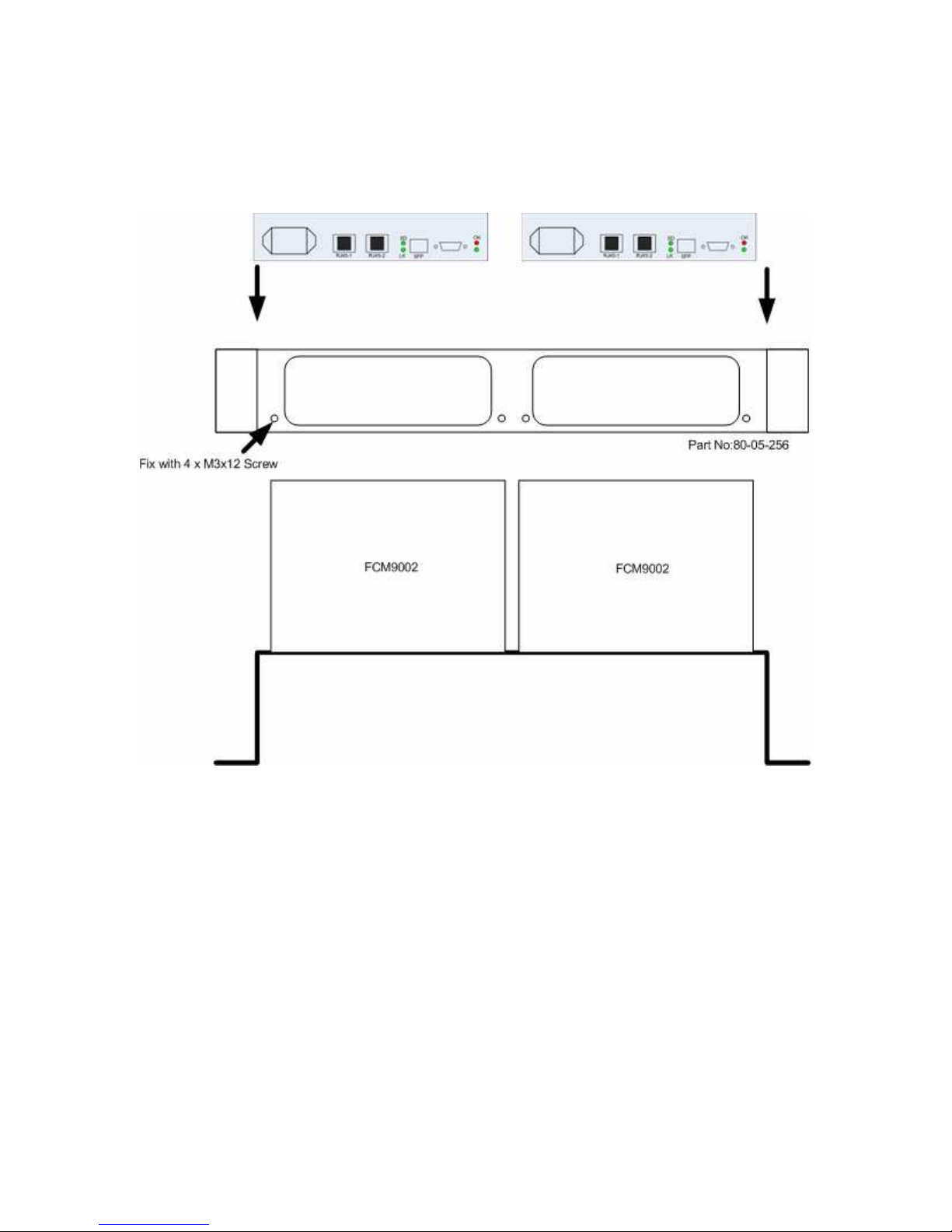
2.4 Rackmounting
The FCM9002 is a standalone, desktop unit however it may be mounted in a
standard 19 inch rack using the rack mounting kit, part number 80-05-256.
To mount the FCM9002 in the 19 inch rack mount adaptor first remove the two
M3x12 screws and washers from the rear panel of the unit. Then align the
FCM9002 rear panel with the mounting bracket, and secure the unit to the
adaptor using the previously removed screws.
When rackmounting, please ensure that the bitswitches on the underside are
correctly configured prior to mounting the units in the rack.
76-02-095 Rev.B Page 27 of 145
Page 28
FCM9002 USER MANUAL
3 OPERATING MODES
The FCM9002 supports multiple modes of operation with support for pushing or
popping tags. The FCM9002 supports two types of VLAN Tag, the basic IEEE
802.1q tag with Ethertype 8100, and referred to as C-Tag or Customer Tag within
this manual. A second Tag type is referred to as the Service Tag, or S-Tag
which has a configurable Ethertype with the default value of 9100.
The operating mode of the FCM9002 is defined in the traffic management section
of the Data Port Setup Menu, see section 4.5.1
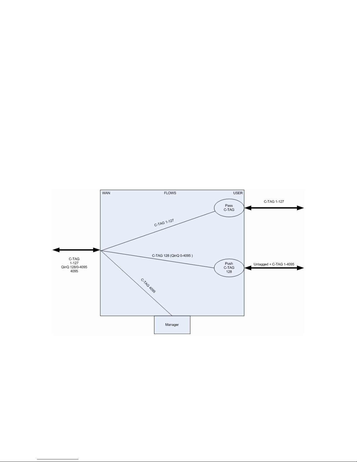
3.1 C-Tag Mode
In C-Tag mode, the FCM9002 will either push an IEEE 802.1q VLAN Tag onto a
previously tagged or untagged frame, or will pass unchanged already tagged
frames. The FCM9002 capabilities in C-Tag mode are shown below:
In C-Tag mode, flows are defined as groups of C-Tag VLAN ID’s. A VLAN ID
may be in the range 1 to 4095. In the above example, there are five flows
defined as well as a management channel connection.
The user ports have the option of operating as an Access port where untagged
frames will have a C-Tag pushed on ingress, and popped on egress. This is
shown for C-TAG 128 which is pushed onto all untagged frames ingressing the
port
76-02-095 Rev.B Page 28 of 145
Page 29
FCM9002 USER MANUAL
Ports may also be configured to act as trunk ports where they will pass frames
that ingress already containing VLAN Tags, and will discard any untagged
frames.
Ports may also be configured for mixed mode operation where they will pass
tagged frames and push a tag onto untagged frames.
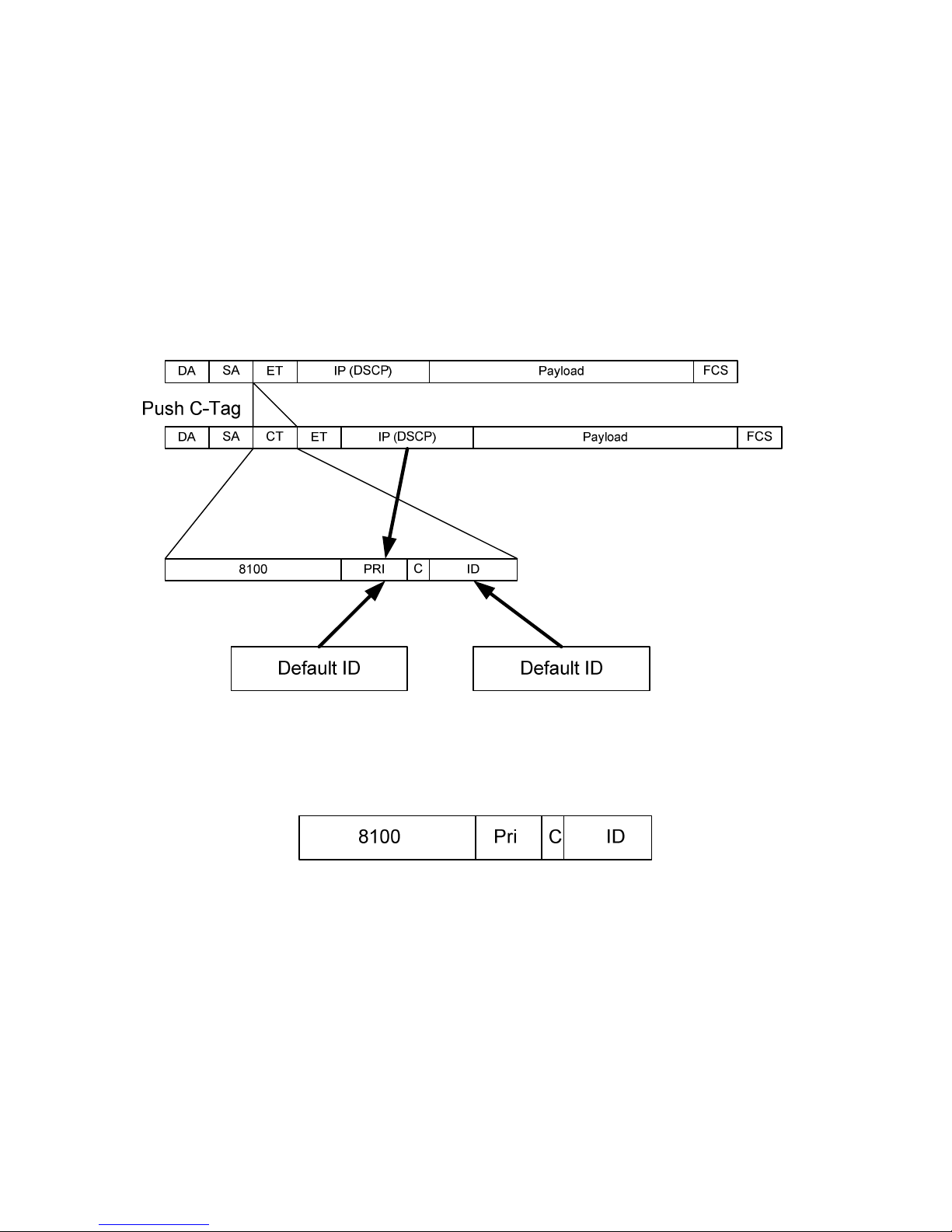
A port may also operate as a QinQ access port pushing a tag onto all incoming
frames including those already tagged, as shown for C-Tag 128 above.
The action of pushing a C-Tag is shown below:
where a four byte VLAN Tag is inserted into the frame after the source address
and before the Ethertype.
A C-Tag is made up of four bytes as shown below:
Where
8100 A 2 byte Ethertype to identify IEEE 802.1q VLAN Tags
Pri A 3 bit priority marker, 0 lowest – 7 highest
C CFI, Canonical Form Indicator normally set to 0.
ID A 12 bit identifier in range 1 to 4095
76-02-095 Rev.B Page 29 of 145
Page 30
FCM9002 USER MANUAL
When a tag is constructed the ID is taken from the default setting for the port.
The Tag Priority may either be set to the port default setting, or for IP packets
with DSCP priorities the tag priority may be based on the packet DSCP value.
3.2 S-Tag Mode
In the FCM9002 Service Tags are used when an extra tag is to be pushed onto
an already tagged frame. The Service Tag has a configurable Ethertype which
by default is set to 9100. QinQ mode is supported by simply configuring the
service tag ethertype to 8100.
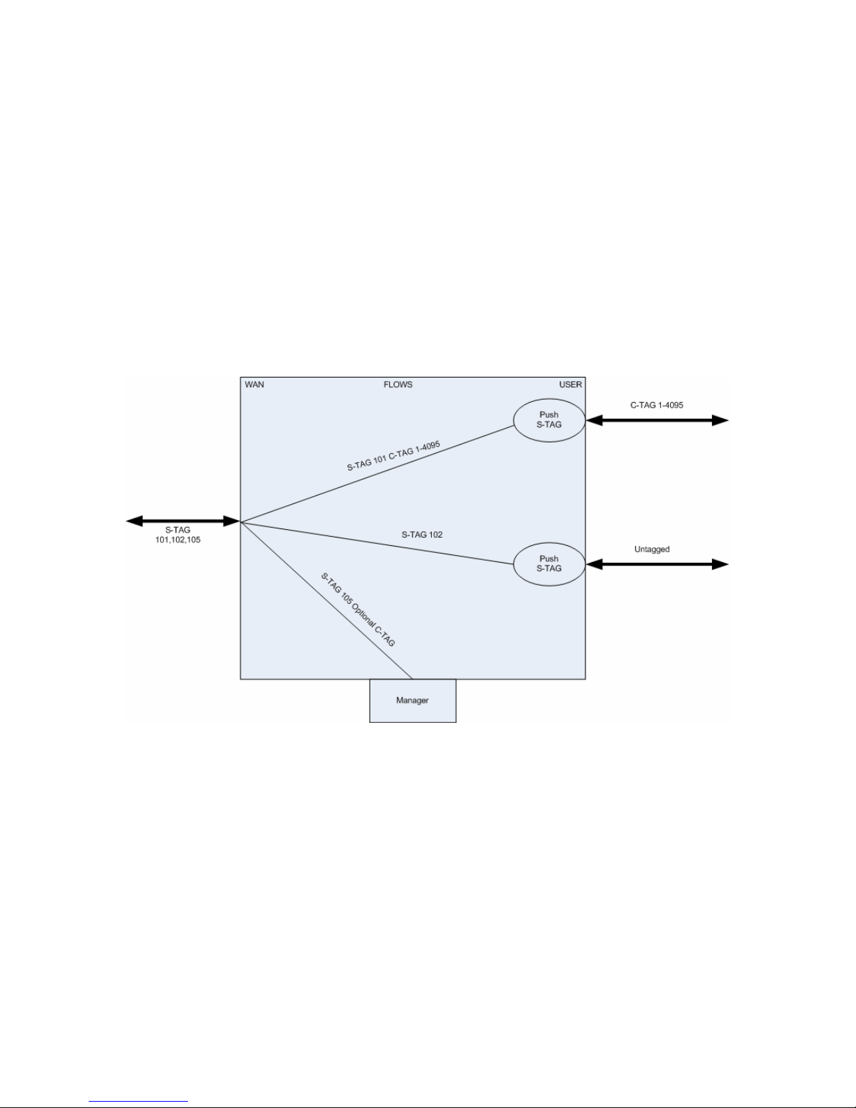
The operation of the FCM9002 in the S-Tag mode is shown below:
In this mode, both tagged and untagged frames are supported on the user ports.
In the example above, port 1 is set to push the S-Tag 101 onto untagged frames
at ingress.
On port 2, frames ingress untagged and have the Stag 102 pushed to give a
packet with an Stag.
76-02-095 Rev.B Page 30 of 145
Page 31
FCM9002 USER MANUAL
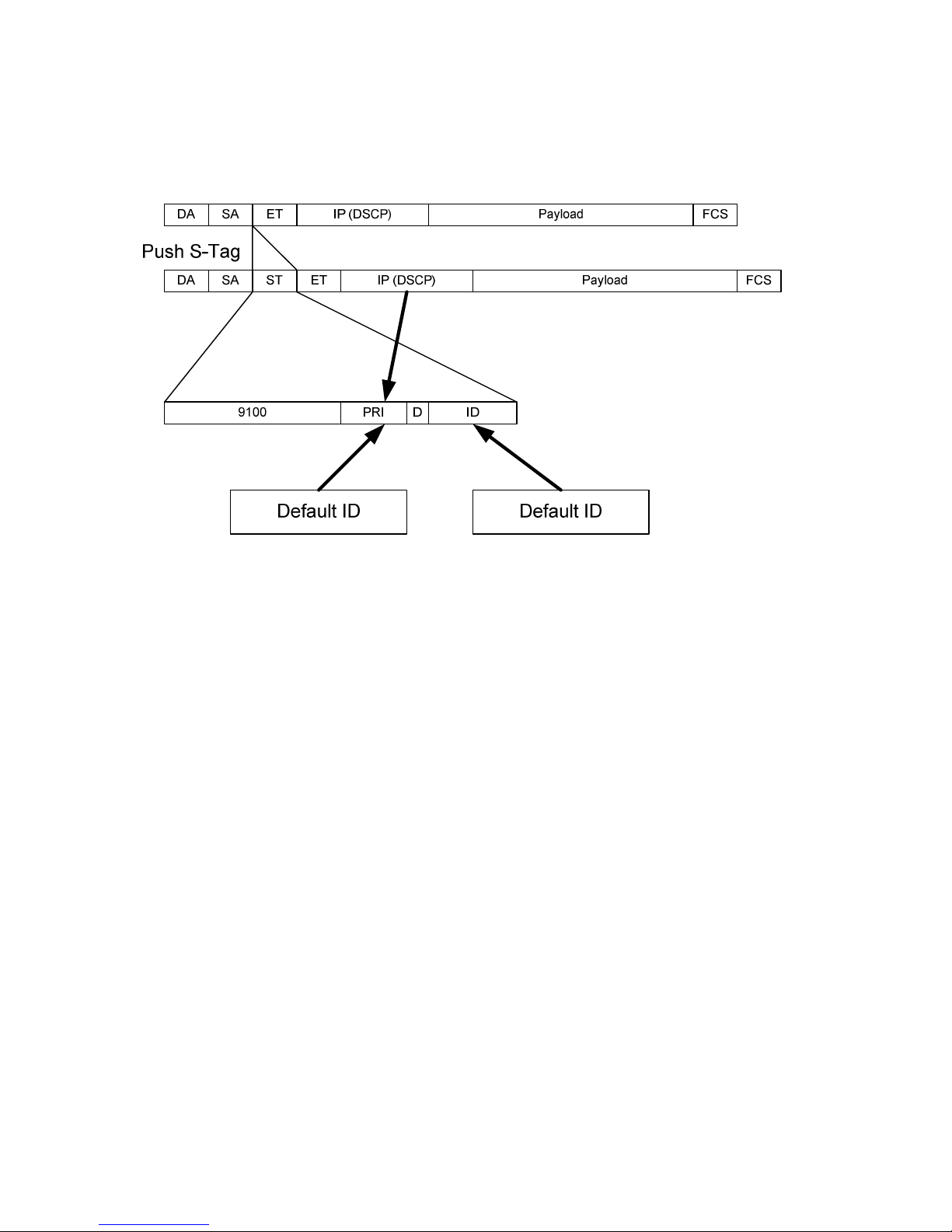
3.2.1 Pushing S-Tag onto Untagged Frame
When an untagged frame ingresses a user port in Stag mode it will have an Stag
pushed as shown below:
Where
9100 S-Tag Ethertype
PRI Priority
D Discard Eligibity
ID Stag ID in range 1 to 4095
When the pushed Stag is constructed it gains the Ethertype from the configured
value. The default value is 9100, and setting this to 8100 will give QinQ
operation, effectively VLAN within VLAN encapsulation.
The priority for an untagged frame may either be set to the default port priority, or
be set to inherit a value based on the incoming IP DSCP priority.
The ID is the value defined for the flow assigned to the port.
76-02-095 Rev.B Page 31 of 145
Page 32
FCM9002 USER MANUAL
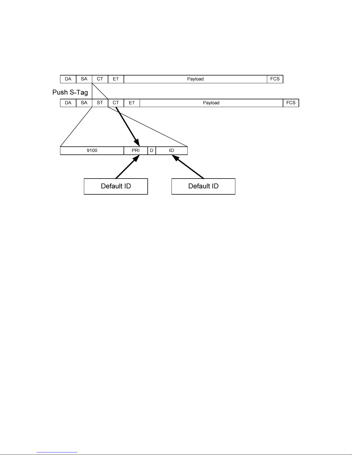
3.2.2 Pushing S-Tag onto Tagged Frame
When a tagged frame ingresses a user port in Stag mode it will have an Stag
pushed as shown below:
Where
9100 S-Tag Ethertype
PRI Priority
ID Stag ID in range 1 to 4095
When the pushed Stag is constructed it gains the Ethertype from the configured
value. The default value is 9100, and setting this to 8100 will give QinQ
operation, effectively VLAN within VLAN encapsulation.
The priority for an tagged frame may either be set to the default port priority, or
be set to inherit a value based on the incoming C-Tag priority.
The ID is the value defined for the flow assigned to the port.
76-02-095 Rev.B Page 32 of 145
Page 33

FCM9002 USER MANUAL
4 CONFIGURATION
The FCM9002 is configured and managed using a simple, menu driven user
interface accessible using either a local craft terminal or remotely using TELNET.
Once you log onto the device the top level menu is as below:
Metrodata FCM9002 “FCM9002” Alarms: Major
MAIN SET-UP
Global status <display>
Operational Modes <menu>
Flows (services) <menu>
Port set-up <menu>
V.24 set-up <menu>
Management Entity <menu>
System <menu>
Update EEPROM
Circuit/Flow Tests <menu>
First CAPITAL – select item
<escape> - exit menu
To select a particular menu item, type the first, or highlighted, capital letter in the
menu description, for example <d> for the Data port set-up, or <m> for
Management.
The type of item is displayed alongside the description:
<menu> There is a sub menu system below this item
<display> There is a status display screen below this item
“value” This item is a direct value which may be modified.
Value items come in two different types, those where a character string must be
entered, or where a list of possible items may be toggled through. For toggle list
items, use <SPACE> to select the next option and <ENTER> to accept.
To exit a menu, and return to the previous level type <ESCAPE>
76-02-095 Rev.B Page 33 of 145
Page 34

FCM9002 USER MANUAL
4.1 System Configuration
The system menu provides the basic administrative configuration items for the
FCM9002. The system menu is shown below:
Metrodata FCM9002 “FCM9002” Alarms: Major
SYSTEM
Time & data <menu>
Node name FCM9002
pRovider ID
Access Control <menu>
weLcome screen <menu>
Software version Main 8.27 / Boot 5.5
Output config <menu>
Input config <menu>
Warm start
Cold start
Event logs <menu>
>
First CAPITAL – select item
> - next page
<escape> - exit menu
and the second page, accessible through the “>” key
Metrodata FCM9002 “FCM9002” Alarms: Major
SYSTEM
<
Zero touch Config <menu>
First CAPITAL – select item
< - next page
<escape> - exit menu
Note, the previous page is accessed using the ‘<’ key, <escape> will ext the
system menu and return to the main setup menu.
4.1.1 Setting the Time and Date
The FCM9002 does not have a non volatile real time clock, instead it uses NTP
to set the date and time following power up. In applications where NTP is not
available, the FCM9002 defaults to providing a simple uptime display.
76-02-095 Rev.B Page 34 of 145
Page 35

FCM9002 USER MANUAL
To configure the NTP parameters select the “Time and Date” menu from the
system menu. The menu is shown below:
Metrodata FCM9002 “FCM9002” Alarms: Major
TIME & DATE
local Time 10:37:25
local Date Mon 12/11/2012
system up time 0d1h14m25s
time Zone GMT+0
NTP server 192.168.0.100
last sync 10:37:22 Mon 12/11/2012
Sync now
First CAPITAL – select item
<escape> - exit menu
If NTP is available, then the time zone and NTP server address must be
configured.
4.1.1.1 Time Zone
Since NTP uses GMT as the baseline time, time zone adjustment is required to
enable the correct time to be displayed wherever the unit is deployed globally.
The time zone may be adjusted by +/- 12 hours from GMT.
4.1.1.2 NTP Server
For NTP to operate correctly, the FCM9002 must be configured with the IP
address of an authoritative NTP time server.
4.1.1.3 Sync Now
If the NTP server has not yet synchronised, it is possible for the user to force a
manual synchronisation by issuing a Sync Now command.
Following power up, the NTP standard calls for a random delay before the NTP
client will request sync from the server, manual sync will speed this process up if
necessary.
4.1.2 Setting the Node Name
To enable identification of the FCM9002 it is useful to enter a meaningful name
for the unit. The node name is entered as a string of upto 32 alpha numeric
characters including spaces.
76-02-095 Rev.B Page 35 of 145
Page 36

FCM9002 USER MANUAL
4.1.3 Provider ID
The provider ID is used during zero touch configuration and is used to identify the
beacons that should be used when multiple beacons are present.
If the provider ID is left blank, the FCM9002 will listen for any beacon whatever
the provider ID, whilst if a value is entered, only beacons with a matching ID will
be used.
The provider ID is not cleared by a cold start, and must be cleared manually if
necessary.
The provider ID is a string of upto 16 characters.
4.1.4 Access Control
The access control menu configures the user access security parameters for the
unit. The Access Control Menu is shown below:
Metrodata FCM9002 "FCM9002_left" Alarms:
Major
ACCESS CONTROL
Password ********
'View' user Enabled
Super Me No
TACACS+ <menu>
First CAPITAL - select item
<escape> - exit menu
4.1.4.1 Setting the Local Password
The local password for the FCM9002 may be changed using the system menu.
The default password is “FCM9002”, however, for deployment a more secure
password may be required.
To change the unit password, select “Password” from the system menu. The
FCM9002 will display the following:
Enter new password
Password >
76-02-095 Rev.B Page 36 of 145
Page 37

FCM9002 USER MANUAL
Enter the new password, upto 16 alphanumeric characters. For security each
character is shown on screen as an asterisk “*”. Once the new password is
entered the display changes to:
Enter new password
Password > ********
Verify >
Re enter the new password to verify the change. If the password is verified the
unit will assume the new password for the next logon.
4.1.4.1.1 Default Unit Password
The default unit password is FCM9002 and is case insensitive.
4.1.4.1.2 Password Recovery
If the unit password is lost, it may be recovered by cold starting the unit using the
bit switches on the underside of the unit. A cold start will erase the unit
configuration and return the unit to factory default, with password FCM9002.
4.1.4.2 View User
The FCM9002 supports two levels of access, Admin and View. An ADMIN user
has full access rights over the FCM9002 configuration. A View user has read
only access to the configuration.
For security, it may be desirable to disable the view user, non password
protected access to the unit. This can be achieved by selecting the View User
menu item and toggling the option to Disabled. When disabled, it will not be
possible to view the configuration without the correct password.
4.1.4.3 Super Me
The Super Me menu option provides a facility to promote an admin user to super
user. In super user mode some further diagnostic menu options are made
available. Super user Mode will only normally be required when instructed by
Metrodata Technical Support in order to extract detailed status information from
the unit.
76-02-095 Rev.B Page 37 of 145
Page 38

FCM9002 USER MANUAL
4.1.4.4 TACACS+
Where greater access control and security is required, the FCM9002 units
support TACACS+ for central password authentication.
Metrodata FCM9002 "" Alarms: Major
TACACS+
Authentication TACACS+,Local
Timeout 3
Retries 3
Server 192.168.100.45
Encryption key ***********
First CAPITAL - select item
<escape> - exit menu
76-02-095 Rev.B Page 38 of 145
Page 39

FCM9002 USER MANUAL
4.1.4.4.1 Authentication
The FCM9002 supports three modes of password access control and
authentication. The options are:
Local (Default) The password access control is handled
locally by the FCM9002 unit and the unit local
password should be used to log in.
TACACS+, Local In this mode, the FCM9002 unit will attempt to contact
the TACACS+ server for authentication, however if the
server cannot be accessed, it will fall back to local
password administration.
TACACS+ Use TACACS+ for password authentication. If the
server is unavailable, access to the unit will not be
allowed.
4.1.4.4.2 Timeout
The timeout defines how long the FCM9002 unit will wait for a response from the
TACACS+ server. The timeout is specified in seconds in the range 1 to 90
seconds.
4.1.4.4.3 Retries
This defines the number of attempts the FCM9002 unit will make when trying to
access the TACACS+ server. The valid range is 1 to 10.
4.1.4.4.4 Server
This defines the IP address of the TACACS+ Authentication server. When a
login attempt is made, this server will be accessed.
4.1.4.4.5 Encryption Key
This key is used by both the FCM9002 and the TACACS+ server to provide a
secure, encrypted password exchange and authentication. This must be set the
same on both FCM9002 and Server. For security, the key is hidden.
76-02-095 Rev.B Page 39 of 145
Page 40

FCM9002 USER MANUAL
4.1.5 Welcome Screen
This menu allows for a user defined welcome screen to be used rather than the
standard Metrodata screen. By default the user defined screen is disabled but
once enabled it is configured line by line as shown:
Metrodata FCM9002 “FCM9002” Alarms: Major
WELCOME SCREEN
Welcome screen Enabled
1st line This is an example
2nd line of a customised
3rd line Welcome Screen
4th line
5th line You may define upto
6th line 8 lines of text
7th line
8th line Here is line number 8
Clear all text
Display Screen <display>
First CAPITAL – select item
<escape> - exit menu
Once the welcome screen has been defined, it may be displayed for checking by
selecting display screen.
76-02-095 Rev.B Page 40 of 145
Page 41

FCM9002 USER MANUAL
4.1.5.1 Display Screen
This menu displays the welcome screen as it will be seen by users attempting to
log on to the unit.
Metrodata FCM9002 “FCM9002” Alarms: Major
WELCOME SCREEN
------------- This is an example
of a customised
Welcome Screen
You may define upto
8 lines of text
Here is line number 8
<escape> - exit, other key - refresh
4.1.6 Output Config
This menu item allows the user to output the ASCII configuration file to the
screen. If a text capture is enabled the file my be saved and reused to reload the
configuration at a later date if necessary.
When the output config option is selected the following screen appears
Metrodata FCM9002 “FCM9002” Alarms: Major
Start capture then press a key
After transfer, stop capture then press another key
At this point enable the text capture and then press a key to continue.
The configuration file will be output to the screen in an ASCII form, readable but
not really understandable as shown by the extract from a config file shown below:
cfmep.0.ma=0
cfmep.0.mid=101
cfmep.0.if=11
cfmep.0.d=1
cfmep.0.e=1
cfmep.0.s=1
rt.0.d=192.168.0.0
rt.0.i=1
rt.0.ty=3
rt.0.p=2
rt.0.m=255.255.255.0
rt.0.ti=2
rt.1.i=1
rt.1.n=192.168.0.254
rt.1.ty=4
76-02-095 Rev.B Page 41 of 145
Page 42

FCM9002 USER MANUAL
rt.1.p=2
snmp.n=FCM9002
snmp.l=Test Network
welcome.0=This is an example
welcome.1=of a customised
welcome.2=Welcome Screen
welcome.4=You may define upto
welcome.5=8 lines of text.
welcome.8=Here is line number 8
To return the main system menu, stop the text capture and hit any key to
proceed.
4.1.7 Input Config
If a config file has been captured it may be reloaded to the unit using the Input
Config command.
Selecting Input Config gives the following message:
Send File. Esc to end.
Use a send text file option from the terminal package, and select the stored
configuration file. Once the file has been sent, type ESC to finish.
Once loaded the unit will reboot to load the configuration.
If errors are detected in the configuration file, the first error will be reported with
the line number.
4.1.8 Warm Start
A warm start will force the unit to reboot and reload the configuration stored in
the EEPROM. Note, any changes to the configuration made that have not been
saved WILL be lost.
When a TELNET user issues a warm start request, the FCM9002 will indicate
that a warm start is about to take place, and then close the connection.
4.1.9 Cold Start
A Cold Start will erase the configuration EEPROM and return the unit to the
factory default condition as defined by the bit switch settings.
Note, that a cold start will erase all IP addresses and routing table entries and it
is highly likely that remote access will be lost following a cold start.
76-02-095 Rev.B Page 42 of 145
Page 43

FCM9002 USER MANUAL
Due to the drastic nature of a cold start, the command requires user confirmation
before cold starting.
Note, the cold start will not clear the provider id used by the beacon system.
4.1.10 Event Logs
Where unexpected operation is observed, viewing the event logs may give an
indication of when events occurred that may have given rise to the issue.
There are three event logs available to view, along with a full, amalgamated log
of all events as shown:
Metrodata FCM9002 “FCM9002” Alarms: Major
EVENT LOGS
System event log <display>
Alarm event log <display>
Config. event log <display>
Full event log <display>
First CAPITAL – select item
<escape> - exit menu
The individual event logs are shown below:
76-02-095 Rev.B Page 43 of 145
Page 44

FCM9002 USER MANUAL
4.1.10.1 System Event Log
The system event log gives the time of system level events such as system
restarts, or NTP updates.
Metrodata FCM9002 “FCM9002” Alarms: Major
--- System Event Log -- 12/11/2012 10:37:22 clock set via NTP
12/11/2012 09:26:05 NTP failed
12/11/2012 09:23:00 performance log cleared
12/11/2012 09:23:00 rtc needs to be set
12/11/2012 09:23:00 config restored
12/11/2012 09:23:00 event logs cleared
press any key to continue
4.1.10.2 Alarm Event Log
The Alarm event log lists the time of all alarm events including start and finish
time.
Metrodata FCM9002 “FCM9002” Alarms: Major
--- Alarm Event Log -- 12/11/2012 09:26:45 Minor OFF Flow2
12/11/2012 09:26:45 Minor OFF Flow1
12/11/2012 09:26:45 Major OFF LAN1
12/11/2012 09:23:38 Major ON LAN1
12/11/2012 09:23:35 Minor ON Flow2
12/11/2012 09:23:35 Minor ON Flow1
press any key to continue
76-02-095 Rev.B Page 44 of 145
Page 45

FCM9002 USER MANUAL
4.1.10.3 Config Event Log
The config event log shows the time of all configuration changes, though not the
actual changes made. It is often the case that things stopped working after a
configuration change.
Metrodata FCM9002 “FCM9002” Alarms: Major
--- Config Event Log -- 12/11/2012 09:26:45 Config. updated
12/11/2012 09:26:45 Config. updated
12/11/2012 09:26:45 Config. updated
12/11/2012 09:23:38 Config. updated
12/11/2012 09:23:38 Config. updated
12/11/2012 09:23:35 Default config. set
press any key to continue
4.1.10.4 Full Event Log
The full event log shows all events in time order, this log can get quite large so
the individual logs may prove more informative.
Metrodata FCM9002 “FCM9002” Alarms: Major
--- Full Event Log -- 12/11/2012 10:37:22 clock set via NTP
12/11/2012 09:26:45 Config. updated
12/11/2012 09:26:45 Config. updated
12/11/2012 09:26:45 Config. updated
12/11/2012 09:26:45 Minor OFF Flow2
12/11/2012 09:26:45 Minor OFF Flow1
12/11/2012 09:26:45 Major OFF LAN1
12/11/2012 09:26:05 NTP failed
12/11/2012 09:23:38 Config. updated
12/11/2012 09:23:38 Config. updated
12/11/2012 09:23:38 Major ON LAN1
12/11/2012 09:23:35 Minor ON Flow2
12/11/2012 09:23:35 Minor ON Flow1
12/11/2012 09:23:38 Major ON LAN1
12/11/2012 09:23:35 Minor ON Flow2
12/11/2012 09:23:35 Minor ON Flow1
12/11/2012 09:23:35 Default config. set
12/11/2012 09:23:00 performance log cleared
12/11/2012 09:23:00 rtc needs to be set
12/11/2012 09:23:00 config restored
12/11/2012 09:23:00 event logs cleared
press any key to continue
76-02-095 Rev.B Page 45 of 145
Page 46

FCM9002 USER MANUAL
4.1.11 Zero Touch Configuration
The FCM9002 supports a zero touch configuration mode of operation whereby
the unit will power up, listen for a beacon on the management channel and then
automatically request an IP address using DHCP and configuration using TFTP.
The ZTC menu is as shown below:
Metrodata FCM9002 "FCM9002_left" Alarms:
Major
ZERO-TOUCH CONFIG
State Inactive
s/w Upgrade time Never
First CAPITAL - select item
<escape> - exit menu
4.1.11.1 Zero Touch State
This menu item serves as both an enable, and a status display for the units
progress during zero touch configuration.
To enable Zero Touch, which is the normal factory default, select Zero Touch
and toggle the state to START which will initiate the process of checking for a
beacon, and then loading a config file.
To disable the Zero Touch Configuration, change the state to INACTIVE.
The possible states that the zero touch configuration may be in are listed below:
INACTIVE Zero Touch Configuration is disabled.
START Zero Touch Configuration is intialising
LISTENING Zero Touch Configuration is listening for the beacon on the network
port.
FOUND A beacon has been detected and an IP address has been
obtained.
CONFIGURING Zero Touch Configuration is downloading, or trying to
download, the configuration file from the supplied TFTP
server.
76-02-095 Rev.B Page 46 of 145
Page 47

FCM9002 USER MANUAL
CONFIGURED Zero Touch Configuration is complete
4.1.11.2 Software Upgrade Time
Part of the Zero Touch Configuration Beacon protocol is to indicate the current
software revision. When a new software revision has been checked out and is
ready to release the file should be loaded to the TFTP server. The beacon
software version number should be updated and then units that are enabled to
automatically update their software will do so at a pre determined time. To
prevent all units attempting to upgrade at once the time may be defined for each
unit.
The options are:
NEVER Do not automatically upgrade the firmware.
RANDOMIZED Wait a random time of between 0 and 256 minutes
from the beacon.
FIXED Perform the upgrade the defined time.
IMMEDIATELY Perform the upgrade immediately on receiving a
beacon indicating a new version of code is available.
76-02-095 Rev.B Page 47 of 145
Page 48

FCM9002 USER MANUAL
4.2 Management Entity
The Management Entity menu is where the remote access to the FCM9002 is
configured. The top level management entity menu is as below:
Metrodata FCM9002 “FCM9002” Alarms: Major
MANAGEMENT ENTITY
intErface <menu>
Ip <menu>
Udp <menu>
tCp <menu>
sNmp <menu>
Telnet/SSH <menu>
tFtp <menu>
Ping <display>
First CAPITAL – select item
<escape> - exit menu
4.2.1 Interface
The interface menu configures the unit management interface.
Metrodata FCM9002 “FCM9002” Alarm: Major
INTERFACE
State Up
Phys. address 0:C0:81:0:13:ae
DHCP Off
Ip addr 192.168.0.13
Net mask 255.255.255.0
At table <display>
sTats <display>
C-VLAN 101
QinQ/S-VLAN 4095
802.1p priority 7
Override Incoming No
First CAPITAL – select item
<escape> - exit menu
76-02-095 Rev.B Page 48 of 145
Page 49

FCM9002 USER MANUAL
4.2.1.1 STATE
The Management port state may be either UP or DOWN as below:
UP Management port is active and will pass traffic
DOWN Management Port is down and is inactive.
For normal operation the state must be up.
Note, when ZTC is enabled the state shows as down while the unit is listening for
the beacon to determine the correct management WAN interface and the correct
S-Tag/C-Tag combination. As soon as the beacon is received, the state will
automatically assume the UP state.
4.2.1.2 Physical Address
This is a display item only, and shows the unit MAC Address.
4.2.1.3 DHCP
DHCP allows the FCM9002 to get an IP address automatically from a centrally
administered server.
DHCP can be enabled, or disabled where the IP address must be manually
configured on each unit.
When DHCP is enabled, a unit powers up and broadcasts a DHCP request for an
address. Once a server hears the request, it will respond with an address the
unit can use.
DHCP is always enabled when ZTC is used.
4.2.1.4 IP Address
In order to access the FCM9002 remotely it must be configured with an IP
address. This may be obtained either using DHCP, in which case this will be
configured automatically, or Manually if DHCP is disabled.
The IP address should be entered in the format AA.BB.CC.DD
By default, the unit assumes the IP address 169.254.42.42 regardless of whether
DHCP is enabled or not. If a DHCP in enabled and a server does not respond
then it will keep this address, otherwise it will assume the DHCP supplied
address.
76-02-095 Rev.B Page 49 of 145
Page 50

FCM9002 USER MANUAL
4.2.1.5 Net Mask
The network mask is used to differentiate the network address from the host
address. By default this is set to the class B value 255.255.0.0 to agree with the
default IP address of 169.254.42.42
If DHCP is enabled, the net mask is served by the DHCP server and is
configured automatically.
4.2.1.6 AT Table
The AT Table display allows the user to view the device ARP table. This may be
useful when devices are having problems communicating. The ARP table is
shown as below:
Metrodata FCM9002 “FCM9002” Alarms: Major
AT TABLE
------- IP Address Ethernet Address Age
--------------------------------------------------
192.168.0.254 0.60.3e.99.f.e2 11231
192.168.0.100 0.9.5b.1c.2e.a8 6967
<Escape> - exit, other key – refresh
76-02-095 Rev.B Page 50 of 145
Page 51

FCM9002 USER MANUAL
4.2.1.7 Stats
To enable diagnosis of communication problems a full set of SNMP statistics are
provided for the management interface as shown below:
Metrodata FCM9002 “FCM9002” Alarms: Major
Interface Statistics
------------------- ifInOctets 287935
ifInUcastPkts 2443
ifInNUcastPkts 406
ifInDiscards 0
ifInErrors 0
ifInUnknownProtos 0
ifOutOctets 2564
ifOutUcastPkts 109
ifOutNUcastPkts 53
ifOutErrors 0
ifOutQLen 0
<Escape> - exit, other key - refresh
4.2.1.8 C-VLAN
This is the value of IEEE 802.1q TAG that is used by the manager when
transmitting or receiving frames.
When frames are to be sent with a TAG, the acceptable values are in the range 1
to 4095.
When frames are to be sent untagged, the value is NONE.
4.2.1.9 QinQ/S-VLAN
This value defines the outer tag that will be used. Acceptable values for tagged
frames are 1 to 4095, or NONE for untagged.
Note, the Ethertype used for the S-VLAN is configurable, but defaults to 9100.
4.2.1.10 802.1p Priority
When the manager transmits tagged frames, they are sent with the configured
priority.
0 Low Priority to 7 Highest Priority
76-02-095 Rev.B Page 51 of 145
Page 52

FCM9002 USER MANUAL
4.2.1.11 Override Incoming
The override incoming priority option is available in C-Tag mode and allows the
priority of the management VLAN VID to be promoted to the value configured in
the 802.1p priority setting.
The options are:
No Leave management frames unchanged
Yes Overwrite the priority in all frames with the management
VLAN VID.
76-02-095 Rev.B Page 52 of 145
Page 53

FCM9002 USER MANUAL
4.2.2 IP Configuration
The IP configuration menu is as shown below:
Metrodata FCM9002 “FCM9002” Alarms: Major
IP
default TTL 32
DSCP priority 0
Routing table <display>
Forwarding Disabled
Stats. <display>
First CAPITAL – select item
<escape> - exit menu
4.2.2.1 Default TTL
When packets are generated by the FCM9002 manager, they will be transmitted
with the value configured here. It is unlikely that the default value of 32 will need
to be changed, though it may be set in the range 1 to 255 bearing in mind that
the TTL value is decremented by 1 for each router on the route.
4.2.2.2 DSCP Priority
When packets are transmitted by the FCM9002 manager, they will be transmitted
with the configured DSCP ( Differentiated Services Code Point ) value. DSCP
may be specified in the range 0 to 63 with 0 being best effort.
The exact meaning and priority of DSCP values are network dependant , though
the following table usually applies for traffic classification.
Discard
Probability
Class 1 Class 2 Class 3 Class 4
Low DSCP 10 DSCP 18 DSCP 26 DSCP 34
Medium DSCP 12 DSCP 20 DSCP 28 DSCP 36
High DSCP 14 DSCP 22 DSCP 30 DSCP 38
76-02-095 Rev.B Page 53 of 145
Page 54

FCM9002 USER MANUAL
4.2.2.3 Routing Table
In order to operate within a routed network, and access hosts that are not located
on the same subnet, the routing table must be configured. The FCM9002
supports static routing only.
The routing table menu is as shown below:
Metrodata FCM9002 “FCM9002” Alarms: Major
Destination Next Hop I/F Type Prot. Age Mask
---------------------------------------------------------------------
192.168.0.0 0.0.0.0 Mgmt direct local 12045 255.255.255.0
0.0.0.0 192.168.0.254 Mgmt indirect local 12046 0.0.0.0
A – add entry
D – delete entry
any other key to exit:
To add a new route you need to know three parameters,
Destination Network Address
Destination Network Mask
Next Hop Router Address
For example, the table above has the default route included where
Destination = 0.0.0.0
Mask = 0.0.0.0
Next Hop = 192.168.0.254
When DHCP is enabled, the default route will be added automatically if it is
supplied by the DHCP server.
4.2.2.4 Forwarding
The FCM9002 does not support routing between its ports, only switching and
therefore Forwarding is disabled.
76-02-095 Rev.B Page 54 of 145
Page 55

FCM9002 USER MANUAL
4.2.2.5 IP Statistics
The manager provides a full set of SNMP statistics for the IP layer as shown
below:
Metrodata FCM9002 "FCM9002_Right" Alarms: Major
IP Statistics
------------ ipInReceives 3031
ipInHdrErrors 0
ipInAddrErrors 0
ipForwDatagrams 0
ipInUnknownProtos 0
ipInDiscards 0
ipInDelivers 3031
ipOutRequests 2861
ipOutDiscards 0
ipOutNoRoutes 0
ipReasmReqds 0
ipReasmOKs 0
ipReasmFails 0
ipFragOKs 0
ipFragFails 0
ipFragCreates 0
ipRoutingDiscards 0
press any key to continue
The following two screens display the ICMP protocol statistics
icmpInMsgs 362
icmpInErrors 0
icmpInDestUnreachs 0
icmpInTimeExcds 0
icmpInParmProbs 0
icmpInSrcQuenchs 0
icmpInRedirects 0
icmpInEchos 362
icmpInEchoReps 0
icmpInTimestamps 0
icmpInTimestampReps 0
icmpInAddrMasks 0
icmpInAddrMaskReps 0
icmpOutMsgs 362
icmpOutErrors 0
icmpOutDestUnreachs 0
icmpOutTimeExcds 0
icmpOutParmProbs 0
icmpOutSrcQuenchs 0
icmpOutRedirects 0
press any key to continue
icmpOutEchos 0
icmpOutEchoReps 364
icmpOutTimestamps 0
icmpOutTimestampReps 0
icmpOutAddrMasks 0
icmpOutAddrMaskReps 0
press any key to continue
76-02-095 Rev.B Page 55 of 145
Page 56

FCM9002 USER MANUAL
4.2.3 UDP
The FCM9002 uses UDP for SNMP management. This menu displays the port
numbers used and statistics.
Metrodata FCM9002 “FCM9002” Alarms: Major
UDP
snmp Port 161
snmp Trap port 162
Stats <display>
First CAPITAL – select item
<escape> - exit menu
4.2.3.1 SNMP Ports
As defined by the IANA, the standard UDP port numbers are
SNMP 161
SNMP Trap 162
76-02-095 Rev.B Page 56 of 145
Page 57

FCM9002 USER MANUAL
4.2.3.2 Statistics
The FCM9002 provides the SNMP UDP layer mib statistics
Metrodata FCM9002 "FCM9002_Right" Alarms: Major
UDP Statistics
------------- udpInDatagrams 2340
udpNoPorts 323
udpInErrors 0
udpOutDatagrams 2071
press any key to continue
4.2.4 TCP
The TCP menu gives information relating to the TCP layer
Metrodata FCM9002 “FCM9002” Alarms: Major
TCP
Stats. <display>
Conn. table <display>
First CAPITAL – select item
<escape> - exit menu
TCP is a connection orientated protocol and the conn table gives information
relating to current TCP sessions, whilst the stats menu shows the SNMP MIB
TCP statistics.
76-02-095 Rev.B Page 57 of 145
Page 58

FCM9002 USER MANUAL
4.2.4.1 Statistics
The TCP statistics available are as shown:
Metrodata FCM9002 "FCM9002_Right" Alarms: Major
TCP Statistics
------------- tcpActiveOpens 7
tcpPassiveOpens 0
tcpAttemptFails 0
tcpEstabResets 0
tcpInSegs 450
tcpOutSegs 550
tcpRetransSegs 0
tcpInErrs 0
tcpOutRsts 0
press any key to continue
4.2.4.2 Connection Table
The Connection table displays the list of the currently open sessions as shown
Metrodata FCM9002 "FCM9002_Right" Alarms: Major
TCP CONNECTION TABLE
------------------- State LocalAddress Loc Port RemAddress Rem Port
----------------------------------------------------------- established 192.168.0.13 23 192.168.100.48 2711
synReceived 192.168.0.13 23 192.168.100.48 2687
<Escape> - exit, other key – refresh
The FCM9002 supports five concurrent Telnet or other TCP protocol sessions.
An attempt to open a sixth session will be rejected by the FCM9002.
Due to the five session limit, it is vitally important that a timeout value is used for
Telnet to force close them after a period of inactivity.
76-02-095 Rev.B Page 58 of 145
Page 59

FCM9002 USER MANUAL
4.2.5 SNMP
The FCM9002 supports management access via SNMP V1 or V2c, which may
be configured using the SNMP menu,
Metrodata FCM9002 "FCM9002 " Alarms: Major
SNMP
Read community public
Write community public
Trap community public
Managers <menu>
contact Person Metrodata Limited,Fortune House,
Crabtree Office Village,Eversl..
Node name FCM9002
Location Test Network
Stats. <display>
trap Alarms <menu>
First CAPITAL - select item
<escape> - exit menu
4.2.5.1 Communities
The FCM9002 supports separate communities for Read, Write and Trap access.
Communities provide a limited level of security within SNMP V1 as only requests
with the correct community name will be actioned.
By default, all communities are set to PUBLIC.
The community names must be changed to match those used by the network
management system.
76-02-095 Rev.B Page 59 of 145
Page 60

FCM9002 USER MANUAL
4.2.5.2 Managers
The FCM9002 supports upto 10 separate SNMP Managers which may be
configured using the managers menu system. Only SNMP polls and get/set
requests from configured managers will be accepted.
The managers menu is as below:
Metrodata FCM9002 "FCM9002 " Alarms: Major
MANAGERS
1 - 192.168.100.45 <menu>
2 - 192.168.100.70 <menu>
Add manager <menu>
First CAPITAL - select item
<escape> - exit menu
Here there are two managers currently configured which may be selected for
viewing, editing by typing the manager number, in this case 1 which will then
display the parameters for this manager:
Metrodata FCM9002 "FCM9002_Right" Alarms: Major
1 - 192.168.100.45
IP address 192.168.100.45
Access rights Read-Write
receives Traps Yes
snmp Version SNMPv2c
Remove manager
First CAPITAL - select item
<escape> - exit menu
The parameters required for an SNMP manager are the IP address. Note, that
the routing table must be configured where the manager is not on the same
subnet as the FCM9002.
The manager configuration controls the access rights that the manager has,
which may be NONE, READ-ONLY, or READ-WRITE.
The manager may also be set up for traps, if enabled the FCM9002 will generate
traps destined for this manager when alarm events occur.
The FCM9002 supports SNMP V1 or V2c on a per manager basis.
76-02-095 Rev.B Page 60 of 145
Page 61

FCM9002 USER MANUAL
If a manager is no longer required, the it maybe removed.
4.2.5.2.1 Dying Gasp Trap
When multiple managers are configured, the FCM9002 will issue the dying gasp
trap to each manager in turn starting with manager 1.
As there is limited time to generate the Dying Gasp Trap it is quite likely that
higher numbered managers will not receive this trap as the power will have failed
by then.
4.2.5.3 Contact Person
The SNMP Contact person is the RFC-1213 MIB-2 SysContact MIB definition.
This item is a string of upto 255 characters.
4.2.5.4 Node Name
The SNMP Node Name is the MIB-2 SysName MIB definition. This item is a
string of up to 255 characters.
4.2.5.5 Location
The SNMP Location is the MIB-2 SysLocation MIB definition. This item is used
to show the detailed location of the device. This item is a string of upto 255
characters.
76-02-095 Rev.B Page 61 of 145
Page 62

FCM9002 USER MANUAL
4.2.5.6 SNMP Statistics
The FCM9002 provides a display of the MIB-2 SNMP statistics as shown:
Metrodata FCM9002 "FCM9002" Alarms: Major
SNMP Statistics
-------------- snmpInPkts 2165
snmpOutPkts 2216
snmpInBadVersions 0
snmpInBadCommunityNames 0
snmpInBadCommunityUses 0
snmpInASNParseErrs 0
snmpInTooBigs 0
snmpInNoSuchNames 0
snmpInBadValues 0
snmpInReadOnlys 0
snmpInGenErrs 0
snmpInTotalReqVars 6023
snmpInTotalSetVars 0
snmpInGetRequests 2018
snmpInGetNexts 147
snmpInSetRequests 0
snmpInGetResponses 0
snmpInTraps 0
press any key to continue:
snmpOutTooBigs 0
snmpOutNoSuchNames 322
snmpOutBadValues 0
snmpOutGenErrs 0
snmpOutGetRequests 0
snmpOutGetNexts 0
snmpOutSetRequests 0
snmpOutGetResponses 2166
snmpOutTraps 51
press any key to continue
76-02-095 Rev.B Page 62 of 145
Page 63

FCM9002 USER MANUAL
4.2.5.7 Trap Alarms
The Trap Alarm Menu allows the user to control which of the wide range of
possible alarms generated by the FCM9002 should generate traps.
Under this menu are all the port and other sources of alarms and each alarm is
listed and may be set to generate a Trap, or if it is deemed unimportant, No-Trap.
The alarm types supported by the FCM9002 are listed below:
LKDN Link Down
LLF Link Loss Forwarding
FEFI Far End Fault Indication, 100BaseFX only
OAM Loss of link OAM connectivity messages
LOS Loss of Optical Signal
NF SFP Not Fitted
RDI Receiving Service CFM RDI indications
NP No CFM peer MEP discovered
XCON Misconnected CFM MEP
ERR Errored CFM messages
REM Loss of remote CCM messages
MAC Remote user port failure
RDI Remote Defect Indication
SLA SLA not being met
SFPA SFP Diagnostic Alarm
SFPW SFP Diagnostic Warning
OTDR SFP OTDR value available
76-02-095 Rev.B Page 63 of 145
Page 64

FCM9002 USER MANUAL
4.2.6 Telnet/SSH
The FCM9002 supports remote access using either TELNET or the more secure
encrypted SSH V2. The menu is shown below:
Metrodata FCM9002 "FCM9002_left" Alarms:
Major
TELNET/SSH
Access Method SSH
Timeout 600
First CAPITAL - select item
<escape> - exit menu
4.2.6.1 Access Method
The access method selects between Telnet at SSH V2. By default following a
cold start, Telnet is available.
If SSH access is enabled, two concurrent sessions are supported and access
using Telnet is prevented.
The FCM9002 SSH V2 server has been verified with several of the more popular
SSH clients including:
PUTTY
TeraTerm TTSSH
BitVise SSH Client
Note, when connecting to the FCM9002 SSH server there will be a delay of upto
15 seconds whilst the secure key calculation and key exchange process occurs.
Once this is completed, the user interface operates as normal.
76-02-095 Rev.B Page 64 of 145
Page 65

FCM9002 USER MANUAL
4.2.6.2 Timeout
To ensure that Telnet/SSH sessions are not left open, an inactivity timer is
provided which will automatically shut down the session if it is not being used.
The default setting in 60 seconds, however a more practical value is 600, 10
minutes.
Setting the timeout to 0, disables the timer – however this must be done with
care as unwanted Telnet/SSH sessions will never be cleared.
76-02-095 Rev.B Page 65 of 145
Page 66

FCM9002 USER MANUAL
4.2.7 TFTP
The FCM9002 uses the TFTP protocol to enable file transfers into or out of the
device. TFTP is a client/server protocol and the FCM9002 is capable of
operating as either client or server.
4.2.7.1 Client Mode
In client mode, an external TFTP server must be running on a machine
somewhere that is accessible at the configured address.
Metrodata FCM9002 "FCM9002" Alarms: Major
TFTP
Mode Client
remote IP 192.168.0.100
Get new software <display>
Boot s/w upgrade <display>
get Config.
Put config.
put Report
First CAPITAL - select item
<escape> - exit menu
4.2.7.1.1 Remote IP
This is the IP address of the remote TFTP server which must be running in order
for a TFTP transfer to take place.
76-02-095 Rev.B Page 66 of 145
Page 67

FCM9002 USER MANUAL
4.2.7.1.2 Get New Software
This menu item is used to upgrade the system application firmware. Selecting
this option will lead to the following display:
Metrodata FCM9002 "FCM9002_Right" Alarms: Major
TFTP Software Upgrade
CAUTION: Proceding further will mean that the unit must be restarted, and the performance log may be cleared, even if the
upgrade is unsuccessful. Are you sure you wish to continue?
At the prompt, confirm the action by typing <Y>, for Yes. The menu will now
prompt for the file name.
Enter the file name.
The file will now download, with a block count to show activity and will then
prompt the user to verify that the correct file has been downloaded
File name: FCM9002.87
Blocks received: 4371
File received successfully, length 2237623.
File contains:
Unit Description: FCM9002
Software Version: 8.7.[ib].1.24 25/10/2012 07:29:52 unreleased
This will replace:
Unit Description: FCM9002
Software Version: 8.7.[ib].1.34 08/11/2012 15:40:13 unreleased
The software will now be updated.
Are you sure this is what you want to do?
If this is correct, confirm <Y>, otherwise type <N> to stop the download. If the
download is stopped, the system must be restarted.
Once the firmware upgrade has completed, the unit will automatically restart with
the new firmware image and reload the configuration from EEPROM.
76-02-095 Rev.B Page 67 of 145
Page 68

FCM9002 USER MANUAL
4.2.7.1.2.1 Failsafe Upgrade
The system software upgrade procedure uses a failsafe mechanism to prevent a
system becoming unusable. When a unit is shipped from the factory, the base
version of the application is stored in a locked portion of the flash memory.
When a new version is loaded via TFTP it will be programmed into flash as a
second image, the original image is never erased, or overwritten. When the
system reboots, the boot software compares the loaded versions of firmware and
executes the most upto date version.
4.2.7.1.3 Boot Software Upgrade
There may be occasions when new features added to the main application code
cannot be supported without changes to the boot loader code. The Boot S/W
upgrade facility enables the boot software to be upgraded, and also installs a
new base application.
Selecting the Boot Upgrade option will lead to the prompt:
Metrodata FCM9002 "FCM9002_left" Alarms:
Major
TFTP Boot Software Upgrade
CAUTION: Proceding further will mean that the unit must be re-started,
and the performance log may be cleared, even if the upgrade is
unsuccessful.
Are you sure you wish to continue? y
File name: FCM9002b.821
Blocks received: 5268
File received successfully, length 2697124.
File contains:
Unit Description: FCM9002
Software Version: 8.21.[mh].3.6 19/06/2013 13:15:33 unreleased
This will replace:
Unit Description: FCM9002
Software Version: 8.16.[mh].1.2 08/05/2013 23:37:46 unreleased
The software will now be updated.
Are you sure this is what you want to do?
Confirming Y at the prompt, and the system will reprogram the flash and then
restart with the new boot and application code.
Note, Please ensure that the unit is not powered down during the boot
programming process as this may corrupt the boot software and prevent the
system from operating.
76-02-095 Rev.B Page 68 of 145
Page 69

FCM9002 USER MANUAL
4.2.7.1.4 Get Config
To load a configuration file that has been saved on the TFTP server use the Get
Config command. Enter the file name for the configuration file and it will then be
loaded, validated and stored in EEPROM. The system will then be rebooted with
the new configuration.
4.2.7.1.5 Put Config
To save the running configuration use the Put Config command to load the file
onto the tftp server. Enter the filename and perform the transfer.
4.2.7.2 Server Mode
The FCM9002 can also be operated in TFTP server mode by setting Mode to
server, as shown:
Metrodata FCM9002 "FCM9002_Right" Alarms: Major
TFTP
Mode Server
remote IP 192.168.0.100
Software file name software
Config. file name config
First CAPITAL - select item
<escape> - exit menu
76-02-095 Rev.B Page 69 of 145
Page 70

FCM9002 USER MANUAL
4.2.7.2.1 Remote IP
The IP address is that of the remote client which will perform the transfer. In the
event that the client sits behind a NAT enabled firewall, the external IP address is
the one that must be configured.
4.2.7.2.2 Software File Name
This is the filename of a file that if downloaded, will be assumed to be a new
software load.
When this file is downloaded, the unit will verify the transfer and then program
the new firmware. Once upgraded the unit will restart automatically.
From a windows pc, the tftp transfer command would be as below
tftp –i device_ip_address put application_filename device_filename
4.2.7.2.3 Config File Name
This is the filename that will be uploaded/downloaded from the FCM9002 as a
configuration file. When a new configuration file is PUT onto the device, once
loaded the unit will automatically restart.
4.2.8 Ping
To provide connectivity checking capability the FCM9002 can generate ICMP
ping requests to a configured IP address.
Once the ping is running, the display is as below:
Metrodata FCM9002 "FCM9002_Right" Alarms: Major
Destination: 192.168.0.100
press any key to stop test
sending...okay, time=3.4ms
sending...okay, time=1.9ms
sending...okay, time=1.9ms
sending...okay, time=1.9ms
sending...okay, time=1.9ms
sending...okay, time=1.9ms
sending...okay, time=1.9ms
sending...okay, time=1.9ms
76-02-095 Rev.B Page 70 of 145
Page 71

FCM9002 USER MANUAL
4.3 V.24 Set-up
The default setting for the V24 terminal port is
19200, 8bit, No Parity, 2 Stop Bits
The V.24 menu configures the terminal port for local access to the FCM9002..
Metrodata FCM9002 "FCM9002" Alarms: Major
V.24 SET-UP
Usage Console
Console set-up <menu>
First CAPITAL - select item
<escape> - exit menu
4.3.1 Usage
To provide security for the unit the local terminal interface may be disabled to
prevent access.
Usage Console The external console port is active
Usage Disabled The external console port is disabled
4.3.2 Console set-up
The console setup menu defines the parameters for the serial port and also for
the display mode.
Note, that when Zero Touch mode is enabled, the console port will be disabled
from power up.
76-02-095 Rev.B Page 71 of 145
Page 72

FCM9002 USER MANUAL
4.3.2.1 Terminal Type
To give maximum flexibility and interoperability with most terminals / terminal
emulator programs the display may take the following modes:
TTY Simple scrolling menu system
VT100/VT220 Cursor controlled menu system
ANSI Cursor controlled, and highlighted menu system.
4.3.2.2 Via Modem
When the FCM9002 is connected via a dial up modem, the unit may be
configured to close the management session when the modem drops DTR.
No Terminal ignores the state of DTR
Yes Management Session closed when DTR negated.
4.3.2.3 Baud Rate
The default terminal baud rate is 19200 baud. It is possible to configure the
terminal to support alternate rates including:
19200
2400
4800
9600
4.3.2.4 Parity
The parity defaults to NONE, however options include
NONE
EVEN
ODD
76-02-095 Rev.B Page 72 of 145
Page 73

FCM9002 USER MANUAL
4.3.2.5 Data Bits
The terminal port defaults to 8 bit characters. The options are
7
8
4.3.2.6 Stop Bits
The terminal defaults to 2 stop bits, the options are
1
2
4.3.2.7 Load New Config
Once all the terminal communications parameters have been configured, the
Load New Command will perform the configuiration changes at which point the
actual terminal must be changed.
76-02-095 Rev.B Page 73 of 145
Page 74

FCM9002 USER MANUAL
4.4 Port Set Up Menu
The data port menu is where all configuration relating to the physical ports and
the traffic flow parameters are configured. The top level data port menu is shown
below:
Metrodata FCM9002 "FCM9002" Alarms: Major
PORT SET-UP
lan1 <menu>
lan2 <menu>
SFP <menu>
First CAPITAL - select item
<escape> - exit menu
The menu is divided into several sections. LAN1, LAN2 and the SFP refer to the
physical ports on the rear of the unit, which may be allocated as either user or
network interfaces
76-02-095 Rev.B Page 74 of 145
Page 75

FCM9002 USER MANUAL
4.4.1 User LAN Port Configuration
When a LAN port is defined as a user port, the LAN port configuration defines the
physical operating parameters for the four 10/100/1000BaseT ports on the rear of
the unit. By default, LAN1 is the WAN/Network port and LAN2 is a user port.
The LAN port menu in user mode, is as shown below:
Metrodata FCM9002 "FCM9002" Alarms: Major
LAN2
State Up
link status Up
max spEed 1000M
max Duplex Full
Auto-negotiation Enabled
negotiated 100M/FD
MDI/MDIX Auto
Tagging & Priority <menu>
L2CP Management <menu>
OAM <menu>
link loss Fwding Disabled
Counters <display>
First CAPITAL - select item
<escape> - exit menu
4.4.1.1 State
The LAN Port State configuration item defines the administrative state of the port.
The port states may be:
UP Port enabled, normal operation
DOWN Port disabled, alarm handling disabled
It is best practice to set ports to the DOWN state when they are not being used
and have no flows defined, as they will then not generate link down traps or show
in the alarmed state.
4.4.1.2 Link Status
The Link Status displays the operational state of the LAN port.
4.4.1.3 Speed
The Speed parameter has two meanings depending upon whether auto
negotiation is enabled or not.
76-02-095 Rev.B Page 75 of 145
Page 76

FCM9002 USER MANUAL
When Auto Negotiation is disabled, the Speed setting sets the operating speed of
the port with valid options of:
10M 10 Base T
100M 100 Base T Fast Ethernet
1000M 1000 Base T Gigabit Ethernet
when Auto Negotiation is enabled, the speed setting defines the maximum speed
advertised to the link partner and the menu item changes to max speed. The
options are as below:
10M Advertise 10M
100M Advertise 10M, 100M
1000M Advertise 10M, 100M, 1000M
4.4.1.4 Duplex
The Duplex parameter has two meanings depending upon whether auto
negotiation is enabled or not.
When Auto Negotiation is disabled, the Duplex setting sets the operating mode of
the port with valid options of:
Half Half Duplex
Full Full Duplex
When Auto Negotiation is enabled, the duplex setting defines the maximum
mode advertised to the link partner and the option changes to max duplex. The
options are as below:
Half Advertise Half Duplex
Full Advertise Half Duplex, Full Duplex
76-02-095 Rev.B Page 76 of 145
Page 77

FCM9002 USER MANUAL
4.4.1.5 Auto Negotiation
Auto Negotiation allows the port to automatically determine the best operating
parameters for the port. If both link partners support auto negotiation then they
will select the best mode that is supported by both devices.
If one link partner does not support auto negotiation, an auto negotiating link
partner will be able to determine the link speed, however it will be unable to
determine the duplex mode so will default to the half duplex state.
An auto port connected to a non auto port is a very common fault on networks
leading to errors on the line when significant traffic is flowing, but appearing to
operate normally when diagnostics like ping are used to test the link.
4.4.1.6 Negotiated
When auto negotiation is enabled, the negotiated display item shows the
operating mode that has be negotiated between the link partners.
10M/HD 10 Base T / Half Duplex
10M/FD 10 Base T / Full Duplex
100M/HD 100 Base T / Half Duplex
100M/FD 100 Base T / Full Duplex
1000M/HD 1000 Base T / Half Duplex
1000M/FD 1000 Base T / Full Duplex
4.4.1.7 MDI / MDIX
There are two possible pin outs for the RJ45 physical ports, one is defined as
MDI and is typically found on data sources such as PC’s or Laptops. The other
is defined as MDIX, or MDI Crossover is typically found on switches. In order to
use a straight through patch cable, an MDI port must connect to an MDI-X port
otherwise crossover cables are required.
The FCM9002 LAN ports support auto switching technology whereby the port will
automatically detect whether it should be MDI or MDIX and will configure itself
accordingly. With auto switching ports, only straight patch cables are required.
76-02-095 Rev.B Page 77 of 145
Page 78

FCM9002 USER MANUAL
The options are:
AUTO Auto switching enabled
MDI Port fixed in MDI configuration
MDIX Port fixed in MDIX configuration
76-02-095 Rev.B Page 78 of 145
Page 79

FCM9002 USER MANUAL
4.4.1.8 OAM
The LAN ports support IEEE802.3 Clause 57 ( 802.3ah ) link OAM for peering or
tunneling with L2CP.
The OAM menu is as below:
Metrodata FCM9002 "FCM9002 " Alarms: Major
OAM, LAN2
Mode Active
Status <display>
counTers <display>
Events <display>
First CAPITAL - select item
<escape> - exit menu
4.4.1.8.1 OAM Mode
The operating mode of the OAM on this port may be defined here. The valid
operating states are:
Disabled Do not generate or respond to OAM packets and discard all OAM
packets received, instead pass received OAM frames to the L2CP
processor where they may be tunneled or discarded.
Active Generate and Respond to OAM packets, only available when the
L2CP action for OAM is Peer.
Passive Respond to OAM packets, only available when the L2CP action for
OAM is Peer.
76-02-095 Rev.B Page 79 of 145
Page 80

FCM9002 USER MANUAL
4.4.1.8.2 OAM Status
The OAM Status display shows the current state of OAM on this link as shown
below:
Metrodata FCM9002 "FCM9002_Right" Alarms: Major
OAM STATUS
--------- | Local | Local | Peer | Peer | Peer | Peer
| Status | Support | Mode | MAC address | VendorInfo | Support
------+----------+---------+------+-------------+------------+------- LAN2 ActiveLoc L
Remote Status
------------Not available
<Escape> - exit, other key – refresh
4.4.1.8.3 OAM Statistics
The OAM statistics show the counts for the various OAM packet types as shown:
Metrodata FCM9002 "FCM9002_Right" Alarms: Major
OAM Statistics
------------- Rx Tx
Unsupported Codes 0 0
Information 0 755
Unique Event 0 0
Duplicate Event 0 0
Variable Request 0 0
Variable Response 0 0
Loopback Control 0 0
Organisation Specific 0 0
<Escape> - exit, C - clear, other key – refresh
76-02-095 Rev.B Page 80 of 145
Page 81

FCM9002 USER MANUAL
4.4.1.8.4 OAM Events
This display lists OAM events that have occurred since the unit was powered up.
4.4.1.9 Link Loss Forwarding
Link Loss Forwarding enables the port state to reflect the status of the full end to
end link status rather than simply the cabled connection between local link
partners.
When a port enters the Link Loss Forwarding alarm state, the port will be forced
to the Link Down state such that the attached equipment will see there is a
problem with this network connection allowing for protocols such as RSTP or
LACP to remove this link from their network map and enable link restoration by
alternative backup links if available.
The Link Loss may be forwarded from:
WAN If the WAN port is down then force the User Port to the Down state.
Flow The end to end flow state is determined using the CFM Connectivity
messages and if these messages are not being received, the link will be
forced down.
4.4.1.10 Tagging and Priority
The tagging and priority menu selects the actions to be taken with untagged
frames.
Metrodata FCM9002 "" Alarms:
Major
TAGGING & PRIORITY, LAN2
Add C-Tag to Untagged
c-tag VID 4095
Priority Source C-Tag, Default
Default Priority 0
First CAPITAL - select item
<escape> - exit menu
76-02-095 Rev.B Page 81 of 145
Page 82

FCM9002 USER MANUAL
4.4.1.10.1 Add C-Tag to
This menu item defines the tagging action to take when a frame arrives at the
port. The possible actions are
None Pass frame unchanged
Untagged Add the default tag as defined to untagged frames
only, pass tagged frames unchanged
All Add default tag to all frames received whether tagged
or untagged
Note, that the default tag ID value must be within the range of ID’s allocated in
flows assigned to this port, otherwise it will be discarded.
Note, in S-Tag mode this option is fixed at NONE since an S-Tag rather than C-
Tag will be pushed as defined in the flow configuration.
4.4.1.10.2 C-Tag VID
This menu item defines the default VLAN ID to add to frames ingressing this port
when the action is set to Add Default Tag.
The available values are in the range 1 to 4095
4.4.1.10.3 Priority Source
The priority source selects the priority for the pushed TAG. The options are
Default Use the default setting for the port
C-Tag,Default Inherit the priority from the incoming c-tag if
present, otherwise use the default value.
DSCP,Default Inherit the priority from the incoming DSCP
marker if present, otherwise use the default.
C-Tag, DSCP, Default Inherit the priority from C-Tag if tagged,
otherwise DSCP if present or use the default.
76-02-095 Rev.B Page 82 of 145
Page 83

FCM9002 USER MANUAL
4.4.1.10.4 Default Priority
This menu item sets the value to be used as the p-tag value within the pushed
VLAN Tag.
Available values are 0 to 7
76-02-095 Rev.B Page 83 of 145
Page 84

FCM9002 USER MANUAL
4.4.1.11 L2CP Management
L2CP, Layer 2 Control Protocols are interactions between nodes on the same
network segment, and as such are generally blocked by switches or bridges.
The purpose of L2CP management is to enable these link layer protocols to be
“tunneled” across the wide area network and regenerated at the remote location.
There are a number of layer 2 protocols and the FCM9002 offers individual
controls for each with the following options:
Discard Discard the Layer 2 Control Protocol on ingress to the
FCM9002.
Tunnel Receive the L2CP packet, encapsulate and then transfer to
the remote end of the link where it can be recovered and
transmitted.
Peer Protocols that the FCM9002 supports may be peered, ie
terminate and generate responses.
L2CP is a proprietary protocol and works by replacing the standard multicast
address which may be blocked or peered by intermediate equipment with the
Metrodata Multicast address 01:C0:81:00:01:02 which will not be blocked and will
be received by an associated FCM9002 unit which will then regenerate the
original L2CP packet.
The L2CP Management Menu is as below:
Metrodata FCM9002 "FCM9002_Left" Alarms: Major
L2CP MANAGEMENT, LAN2
Bridge Group <menu>
GARP Group <menu>
Cisco <menu>
Metrodata <menu>
Other <menu>
L2CP Flow None
First CAPITAL - select item
<escape> - exit menu
76-02-095 Rev.B Page 84 of 145
Page 85

FCM9002 USER MANUAL
4.4.1.11.1 Bridge Group
The bridge group of protocols use the generic multicast destination address
range:
01:80:C2:00:00:00 to 01:80:C2:00:00:0F
Within this range the following protocols are handled by the L2CP management
process:
4.4.1.11.1.1 OAM
The IEEE 802.3 clause 57 (ah) OAM packets are part of the generic slow
protocols group.
Address 01:80:C2:00:00:02
Etype 8809 Slow Protocols
Subtype 3 – OAM
The FCM9002 offers options to Discard, Tunnel or Peer with OAM layer 2 control
packets.
4.4.1.11.1.2 STP/RSTP/MSTP
The STP/RSTP/MSTP BPDU’s use the following addresses
Address 01:80:C2:00:00:00
The FCM9002 offers options to Discard or Tunnel BPDU frames.
76-02-095 Rev.B Page 85 of 145
Page 86

FCM9002 USER MANUAL
4.4.1.11.2 LACP / LACP Marker
LACP, Link Aggregation Control Protocol packets are part of the generic slow
protocols group:
Address 01:80:C2:00:00:02
Etype 8809
Subtype 01 – LACP
Subtype 02 – LACP Marker
The FCM9002 offers options to Discard or Tunnel LACP frames
4.4.1.11.2.1 OSSP
OSSP, Organisational Specific Slow Protocols are part of the generic slow
protocols group:
Address 01:80:C2:00:00:02
Etype 8809
Subtype 10 – OSSP
The FCM9002 offers options to Discard or Tunnel OSSP frames.
4.4.1.11.2.2 LLDP
LLDP, Link Layer Discovery Protocol uses the following
Address 01:80:C2:00:00:0E
Etype 88CC - LLDP
The FCM9002 offers the option of Discard or Tunnel for LLDP frames.
4.4.1.11.2.3 Other Bridge
The Other Bridge protocols cover those protocols using multicast addresses in
the range 01:80:C2:00:00:0x not specifically mentioned above as well as
unrecognized protocols on those addresses already covered.
76-02-095 Rev.B Page 86 of 145
Page 87

FCM9002 USER MANUAL
4.4.1.11.3 GARP Group
The GARP, Generic Attribute Registration Protocols group uses the range of
multicast addresses
01:80:C2:00:00:20 to 01:80:C2:00:00:2F
Within this group there are some well know protocols which are dealt with
individually.
4.4.1.11.3.1 GMRP
GMRP, GARP Multicast Registration Protocol uses the following
Address 01:80:C0:00:00:20
The FCM9002 provides options to Discard or Tunnel GMRP frames.
4.4.1.11.3.2 GVRP
GVRP, GARP VLAN Registration Protocol uses the following
Address 01:80:C2:00:00:21
The FCM9002 provides options to Discard or Tunnel GVRP frames
4.4.1.11.3.3 Other GARP
The other Garp options allows for tunneling of packets with multicast addresses
in the range 01:80:C2:00:00:22 to 01:80:C2:00:00:CF.
The FCM9002 provides options to Discard or Tunnel these frames.
76-02-095 Rev.B Page 87 of 145
Page 88

FCM9002 USER MANUAL
4.4.1.11.4 Cisco Group
The Cisco Group of Layer 2 protocols may be enabled for tunneling or for discard
and the protocols supported are:
CDP Cisco Discovery Protocol 01:00:0C:CC:CC:CC 2000
VTP VLAN Trunk Protocol 01:00:0C:CC:CC:CC 2003
DTP Dynamic Trunking Protocol 01:00:0C:CC:CC:CC 2004
PAgP Port Aggregation Protocol 01:00:0C:CC:CC:CC 0104
UDLD Unidirectional Link Detection 01:00:0C:CC:CC:CC 0111
PVSTP Per VLAN Spanning Tree 01:00:0C:CC:CC:CD 010B
UplinkFast 01:00:0C:CD:CD:CD 200A
4.4.1.11.5 Metrodata Group
The Metrodata group of layer 2 protocols include the following to enable book
ending of devices.
4.4.1.11.5.1 Beacon
The Metrodata Beacon protocol may be discarded, tunneled or peered.
Address 01:C0:81:00:01:01
Etype 88B7
OUI 00C081
4.4.1.11.5.2 L2CP Tunnel
The Metrodata L2CP tunnel protocol may be discarded or Tunnelled
Address 01:C0:81:00:01:02
EType 88B7
OUI 00C081
76-02-095 Rev.B Page 88 of 145
Page 89

FCM9002 USER MANUAL
4.4.1.11.5.3 Other Metrodata
This option will allow for discard or tunnel action for the following range of
Mutlicast addresses
01:C0:81:00:01:03 to 01:C0:81:00:01:0F
4.4.1.11.6 Other Group
The other group provides tunnel control for customer CFM packets. There is the
option to discard, peer or tunnel CFM received on the user ports.
When user CFM is tunneled it is tunneled to the far end and therefore there is no
requirement to use specific domains or associations and be compatible with the
underlying core network.
CFM peering relies on the customer using a domain level which is higher than
the underlying network.
4.4.1.11.7 L2CP Flow
In order to tunnel the L2CP frames to the remote end they must be allocated to a
flow that has previously been configured. Only 1 flow may be allocated and it
must be allocated to the particular user port.
76-02-095 Rev.B Page 89 of 145
Page 90

FCM9002 USER MANUAL
4.4.1.12 Counters
The Counters menu shows the RFC-1213 MIB-2 statistics collected for the LAN
port as shown below:
Metrodata FCM9002 "" Alarms:
Major
Interface Statistics
-------------------ifInOctets 0 Tunnel In Packets 0
ifInUcastPkts 0 Tunnel In Errors 0
ifInNUcastPkts 0 Tunnel Out Packets 0
ifInDiscards 0 Tunnel Out Errors 0
ifInErrors 0
ifInUnknownProtos 0 OAM In Packets 0
ifOutOctets 0 OAM Out Packets 1308
ifOutUcastPkts 0 OAM Out Discards 0
ifOutNUcastPkts 0
ifOutDiscards 0
ifOutErrors 0
<Esc> - exit, C - clear, <Enter> - refresh
76-02-095 Rev.B Page 90 of 145
Page 91

FCM9002 USER MANUAL
4.4.2 User SFP Port Configuration
The SFP port configuration defines the physical operating parameters for the
user SFP port on the rear of the unit.
The SFP port menu for when the SFP is in user mode is shown below:
Metrodata FCM9002 "FCM9002" Alarms: Major
SFP
State Up
link status Up
sfp type 1000BASE-SX
max spEed 1000M
Auto-negotiation Enabled
negotiated 1000M/FD
sFP Management <menu>
Tagging and Priority <menu>
L2CP management <menu>
OAM <menu>
link loss Fwding Disabled
Counters <display>
First CAPITAL - select item
<escape> - exit menu
4.4.2.1 State
The SFP Port State configuration item defines the administrative state of the port.
The port states may be:
UP Port enabled, normal operation
DOWN Port disabled, alarm handling disabled
It is best practice to set the SFP port to the DOWN state when it is not fitted, not
being used or has no flows defined, as it will then not generate link down traps or
show in the alarmed state.
4.4.2.2 Link Status
The Link Status displays the operational state of the SFP port.
4.4.2.3 SFP Type
The SFP type is read from the SFP module and displays the type of module
used.
76-02-095 Rev.B Page 91 of 145
Page 92

FCM9002 USER MANUAL
Note, some cheaper SFP modules are not correctly programmed and in this case
the type will be displayed as UNKNOWN.
4.4.2.4 Speed
The Speed setting sets the operating speed of the port with valid options of:
100M 100 Base FX Fast Ethernet
1000M 1000 Base X Gigabit Ethernet
Auto In the auto mode, the SFP module is read and the port
parameters are set according to the SFP type installed. If a
1000BaseX SFP is installed the port will operate at 1000M,
whilst if a 100BaseFX or OC3 SFP is installed, the port will
operate at 100M.
4.4.2.5 Duplex
The Duplex parameter is valid for 100M operation only, 1000M ports must
operate in full duplex modes.
Half Half Duplex
Full Full Duplex
4.4.2.6 Auto Negotiation
Auto Negotiation allows the port to automatically determine the best operating
parameters for the port. If both link partners support auto negotiation then they
will select the best mode that is supported by both devices.
1000M operation requires Auto Negotiation is enabled, whilst 100M operation
does not support auto negotiation.
76-02-095 Rev.B Page 92 of 145
Page 93

FCM9002 USER MANUAL
4.4.2.7 Negotiated
When auto negotiation is enabled, the negotiated display item shows the
operating mode that has be negotiated between the link partners.
1000M/FD 1000 Base T / Full Duplex
Note, only 1000M operation supports auto negotiation, and only full duplex
operation is supported.
4.4.2.8 SFP Management
The FCM9002 supports reporting of the SFP device type and diagnostic
information. The FCM9002 may also be configured to generate alarms and traps
when the diagnostic readings exceed the alarm or warning thresholds.
The SFP Management menu is shown below:
Metrodata FCM9002 "FCM9002_Fibre" Alarms: none
SFP MANAGEMENT
Device Details <display>
Notifications <menu>
First CAPITAL - select item
<escape> - exit menu
76-02-095 Rev.B Page 93 of 145
Page 94

FCM9002 USER MANUAL
4.4.2.8.1 Device Details
SFP modules include an EEPROM to identify the module capabilities and these
may be read using the SFP device details option. The information display is as
shown below:
Metrodata FCM9002 "" Alarms: Major
SFP Info
------- Transmit
Status Type Vendor Part No. Wavelength
--------------------------------------------------------------------- Good 1000BASE-SX HG GENUINE MXPD-248S-F 850nm
SFP Diagnostic Info
------------------ Diagnostic Current Alarm Threshold Warning Threshold
Item Status Value Unit High Low High Low
--------------------------------------------------------------------- Tx Power OK 8 dBm 8 8 8 8
Rx Power alarm -26 dBm 0 -17 -1 -15
Bias OK 4.2 mA 20.0 1.0 15.0 1.0
Temp OK 44 C 85 -5 80 0
Supply OK 3.28 V 3.60 3.0 3.50 3.10
<Esc> - exit, <Enter> - refresh
4.4.2.8.2 Notifications
The SFP notifications menu configures the actions for alarm and trap generation
when the disagnostic values exceed the alarm or warning threshold values.
Metrodata FCM9002 "FCM9002_Fibre" Alarms: none
NOTIFICATIONS
1 - Temp High Alarm & Warning
2 - Temp Low None
3 - Supply High None
4 - Supply Low None
5 - Bias High None
6 - Bias Low None
7 - Tx Power High None
8 - Tx Power Low None
9 - Rx Power High None
A - Rx Power Low Alarm & Warning
B - SFP Removed None
C - OTDR Fault None
First CAPITAL - select item
<escape> - exit menu
76-02-095 Rev.B Page 94 of 145
Page 95

FCM9002 USER MANUAL
Each diagnostic value may be configured for either:
None No Action
Alarm Generate an Alarm/Trap when the alarm
threshold is exceeded.
Alarm & Warning Generate an Alarm/Trap when either the Alarm
or Warning thresholds are exceeded.
4.4.2.8.3 OTDR SFP module Support
The FCM9002 supports the OpticalZonu SFP modules which have an integrated
OTDR measurement facility. When the OTDR SFP modules are used both fibre
length while operational, and distance to fault measurements are provided.
When an OTDR SFP module is in use the SFP Device Details menu displays
additional information when in a fault condition as shown below:
Metrodata FCM9002 "FCM9002_Copper" Alarms: Major
SFP Info Interface: SFP
------- Transmit
Status Type Vendor Part No. Wavelength
----------------------------------------------------------------------Good 1000BASE-LX OpticalZonu,Corp AF6-151G1-SU 1510nm
Diagnostic Current Alarm Threshold Warning Threshold
Item Status Value Unit High Low High Low
---------------------------------------------------------------Tx Power OK 0 dBm 3 -7 2 -5
Rx Power OK 0 dBm 3 -25 2 -19
Bias OK 57 mA 70 2 60 4
Temp OK 59 C 85 -45 75 -35
Supply OK 3.19 V 3.63 2.97 3.49 3.10
Fault Fault Fibre Last Fault Last Fault Last Fault
Status Distance Length Start Clear Distance
----------------------------------------------------------------------No Fault 458m 875m 16/7/2013 09:33:57
<Esc> - exit, <Enter> - refresh
And when the fault is cleared, the display changes as below:
Metrodata FCM9002 "FCM9002_Copper" Alarms: Major
76-02-095 Rev.B Page 95 of 145
Page 96

FCM9002 USER MANUAL
SFP Info Interface: SFP
------- Transmit
Status Type Vendor Part No. Wavelength
----------------------------------------------------------------------Good 1000BASE-LX OpticalZonu,Corp AF6-151G1-SU 1510nm
Diagnostic Current Alarm Threshold Warning Threshold
Item Status Value Unit High Low High Low
---------------------------------------------------------------Tx Power OK 0 dBm 3 -7 2 -5
Rx Power OK 0 dBm 3 -25 2 -19
Bias OK 57 mA 70 2 60 4
Temp OK 59 C 85 -45 75 -35
Supply OK 3.19 V 3.63 2.97 3.49 3.10
Fault Fault Fibre Last Fault Last Fault Last Fault
Status Distance Length Start Clear Distance
----------------------------------------------------------------------No Fault --- 875m 16/7/2013 09:33:57 16/7/2013 09:34:20 458m
<Esc> - exit, <Enter> - refresh
4.4.2.8.3.1 Fault Status
The Fault status indication gives a display of the current status of the fibre link.
Fault A fault currently exists, and there is an ODTR measurement of the
distance to the fault, along with a timestamp of when the fault was
first detected.
No Fault No fault is currently detected on the Fibre link. A measurement is
provided for the length of the fibre, along with the start/finish
timestamps and distance for the last detected fault.
4.4.2.8.3.2 Fault Distance
When a Fault is indicated, the fault distance displays the distance measured by
the OTDR to the most distant fault. Measurements are made every few seconds
whilst the fault exists, so the display screen may require to be refreshed before
the fault is displayed.
The OpticalZonu OTDR SFP modules provide the distance measurement
accurate to within +/- 10m.
4.4.2.8.3.3 Fibre Length
76-02-095 Rev.B Page 96 of 145
Page 97

FCM9002 USER MANUAL
The fibre length measurement is made by the device when the link is established
and LOS has been negated. The measurement is made and provides an
estimate of the fibre length based on the most distant OTDR value. Accuracy of
the cable length is to within +/- 10m.
When a fault is reported, the cable length shown is the previous measured
length, and the length is recalculated when faults are cleared.
4.4.2.8.3.4 Last Fault Start
When a fault is first detected the time is displayed. If the measured distance
changes by greater then 50m, then a new fault is considered to have been
detected and the time will be updated.
Due to the nature of OTDR measurements, it is occasionally the case that during
the reconnection during fault repair, a new fault may be detected which is equal
to the cable length, though this will be clear due to the short elapsed time
between onset and clearance of the fault condition.
4.4.2.8.3.5 Last Fault Cleared
The time that the fault clears is recorded in the display. This time indicates that
the fault has been cleared and the link has a valid optical signal present.
4.4.2.8.3.6 Last Fault Distance
The last Fault Distance records the OTDR measured distance of the last fault
and will be maintained as a record unless a new fault is detected.
Due to the nature of OTDR measurements, it is occasionally the case that during
the reconnection during fault repair, a new fault may be detected which is equal
to the cable length, though this will be clear due to the short elapsed time
between onset and clearance of the fault condition.
76-02-095 Rev.B Page 97 of 145
Page 98

FCM9002 USER MANUAL
4.4.2.8.3.7 OTDR SFP Trap Support
In the SFP notifications menu, option C enables the OTDR trap generation for
Alarms. The trap definitions may be found in the MET_SFP MIB file.
There are 2 traps generated,
MetSfpOTDRFaultStart This trap is generated when an OTDR fault is
first detected. The trap parameters include the
distance in metres to the fault.
MetSfpOTDRFaultClear The trap is generated when the OTDR fault is
cleared. The trap parameters include the
system up time for both start and clearance of
the fault condition.
4.4.2.9 Tagging and Priority
For an explanation of the tagging and priority menu please refer to section
4.4.1.10
4.4.2.10 L2CP Management
For an explanation of the L2CP configuration, please refer to section 4.4.1.11 of
the User LAN port configuration menu.
76-02-095 Rev.B Page 98 of 145
Page 99

FCM9002 USER MANUAL
4.4.2.11 OAM
For an explanation of the OAM configuration, please refer to section 4.4.1.8 of
the User LAN port configuration menu.
4.4.2.12 Link Loss Forwarding
Link Loss Forwarding enables the port state to reflect the status of the full end to
end link status rather than simply the cabled connection between local link
partners.
When a port enters the Link Loss Forwarding alarm state, the port will be forced
to the Link Down state such that the attached equipment will see there is a
problem with this network connection allowing for protocols such as RSTP or
LACP to remove this link from their network map and enable link restoration by
alternative backup links if available.
The Link Loss may be forwarded from:
WAN If the WAN port is down then force the User Port to the
Down state.
Flow The end to end flow state is determined using the CFM
Connectivity messages and if these messages are not being
received, the link will be forced down.
4.4.2.13 Counters
The Counters menu shows the RFC-1213 MIB-2 statistics collected for the LAN
port as shown below:
Metrodata FCM9002 "" Alarms: Major
Interface Statistics
-------------------ifInOctets 0 Tunnel In Packets 0
ifInUcastPkts 0 Tunnel In Errors 0
ifInNUcastPkts 0 Tunnel Out Packets 0
ifInDiscards 0 Tunnel Out Errors 0
ifInErrors 0
ifInUnknownProtos 0 OAM In Packets 0
ifOutOctets 0 OAM Out Packets 1826
ifOutUcastPkts 0 OAM Out Discards 0
ifOutNUcastPkts 0
ifOutDiscards 0
ifOutErrors 0
<Esc> - exit, C - clear, <Enter> - refresh
76-02-095 Rev.B Page 99 of 145
Page 100

FCM9002 USER MANUAL
4.4.3 WAN ( LAN/SFP ) Port Configuration
The FCM9002 supports either Copper (10/100/1000BaseT) or Fibre (1000BaseX, 100Base-FX) connectivity for the allocated WAN Network Port.. The WAN
mode menus are as shown below for the two modes:
WAN Copper Interface menu:
Metrodata FCM9002 "FCM9002" Alarms: Major
LAN1
State Up
link status Up
max spEed 1000M
max Duplex Full
Auto-negotiation Enabled
negotiated 1000M/FD
MDI/MDIX Auto
Tagging & Priority <menu>
OAM <menu>
Counters <display>
First CAPITAL - select item
<escape> - exit menu
WAN Fibre/SFP Interface menu:
Metrodata FCM9002 "FCM9002" Alarms: Major
SFP
State Up
link status Down
sfp type 1000BASE-LX
max spEed 1000M
Auto-negotiation Enabled
negotiated -- sFP Management <menu>
Tagging & Priority <menu>
OAM <menu>
Counters <display>
First CAPITAL - select item
<escape> - exit menu
76-02-095 Rev.B Page 100 of 145
 Loading...