

Page 1
FC7000 Ethernet Media Converter
Installation Guide
DATE: 21st September 2009
DOCUMENT NO: 76-02-047A
REVISION: A
PREPARED BY: Ian Banbrook
Metrodata Ltd
Fortune House, Crabtree Office Village
Eversley Way, Egham Surrey, TW20 8RY, UK
Tel +44 1 784 744700
Fax: +44 1 784 744730
E-Mail: [email protected]
Page 2

METRODATA LTD FC7000 Media Converter
Installation Guide
76-02-047 Rev A
2 of 12
METRODATA LTD
No part of this publication may be reproduced, transmitted,
transcribed, stored in a retrieval system, or translated into any
language or computer language, in any form or by any means,
electronic, mechanical, magnetic, optical, chemical, manual or
otherwise, without the prior written permission of
Metrodata Ltd, Fortune House,
Crabtree Office Village, Eversley Way,
Egham, Surrey, TW20 8RY, United Kingdom
.
DISCLAIMER
Metrodata Ltd makes no representations or warranties with respect
to the contents hereof and specifically disclaims any implied
warranties or merchantability or fitness for any particular purpose.
Further, Metrodata Ltd reserves the right to revise this publication
and to make changes from time to time in the content hereof without
obligation of Metrodata Ltd to notify any person of such revision or
changes.
Copyright
2009 by Metrodata Ltd,
All Rights Reserved
Page 3

METRODATA LTD FC7000 Media Converter
Installation Guide
76-02-047 Rev A
3 of 12
Document Revision History
20
th
March 2009 XA Document Created
21st September 2009-09-21 A Document Released
Page 4

METRODATA LTD FC7000 Media Converter
Installation Guide
76-02-047 Rev A
4 of 12
TABLE OF CONTENTS
2 INTRODUCTION..........................................................................................................5
3 FC7000 UNIT ...............................................................................................................6
3.1 Power Connector ................................................................................................................................................6
3.2 10/100BaseT RJ45 Port......................................................................................................................................6
3.3 100BaseFX Port ..................................................................................................................................................6
4 FC7X00 CONFIGURATION .........................................................................................7
4.1 Bit Switch 1: Auto Negotiation..........................................................................................................................7
4.2 Bit Switch 2: Speed 100/Speed 10......................................................................................................................8
4.3 Bit Switch 4: Duplex...........................................................................................................................................8
4.4 Bit Switch 5: Auto MDI/MDIX .........................................................................................................................8
4.5 Bit Switch 7: Link State Forwarding................................................................................................................9
5 FC7X00 STATUS LED INDICATORS........................................................................10
5.1 10/100BaseT Link............................................................................................................................................. 10
5.2 10/100BaseT Speed...........................................................................................................................................10
5.3 LOS....................................................................................................................................................................11
5.4 100Base-FX Fibre Port Link/Act LED ...........................................................................................................11
6 LINK STATE FORWARDING.....................................................................................12
6.1 LSF for Fibre Fault ..........................................................................................................................................12
6.2 LSF for Copper Fault....................................................................................................................................... 12
Page 5
METRODATA LTD FC7000 Media Converter
Installation Guide
76-02-047 Rev A
5 of 12
2 INTRODUCTION
The Metrodata FC7x00 is a range of Fast Ethernet Media converter which will convert
between a 10/100BaseT copper twisted pair interface and a 100Base-FX fibre interface.
The FC7x00 utilises a duplex SC Fibre transceiver module and is available in the following
options:
FC7000 100BaseFX 1300nm, Multimode, up to 5km reach
FC7100 100BaseFX 1310nm, Single-mode, up to 30km reach
FC7200 100BaseFX 1310nm, Single-mode, up to 70km reach
Despite these quoted maximum operating distances for the FC7X00 products, specific
installations may only operate over lower distances due to the variations in losses of
different types of fibre cable, the use of connecting fibre cables, or patch panels. When
operating over 50% of the maximum distances it is advisable to calculate all fibre optic
connector and cable losses and compare these with the fibre optic loss budget specified
for this product.
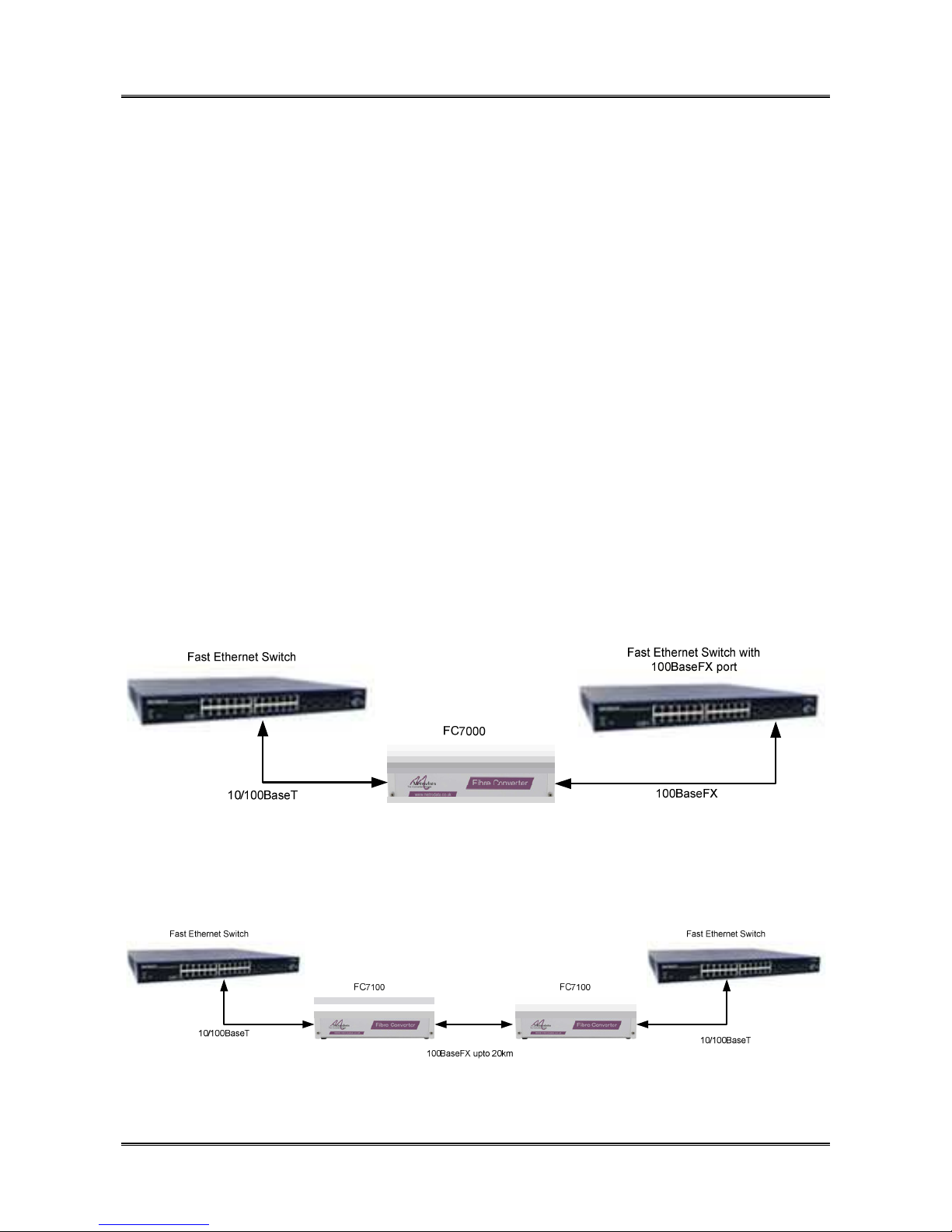
The FC7x00 may be used for simple media conversion to enable connection of a twisted
pair port on a switch to a fibre port on another switch as shown below:
Figure 1: FC7000 Media Conversion
Alternatively, the FC7000 may be used to extend the reach of a twisted pair connection
from 100m to over 20km by conversion to fibre as shown below:
Figure 2: FC7100 Link Extension
Page 6
METRODATA LTD FC7000 Media Converter
Installation Guide
76-02-047 Rev A
6 of 12
3 FC7000 UNIT
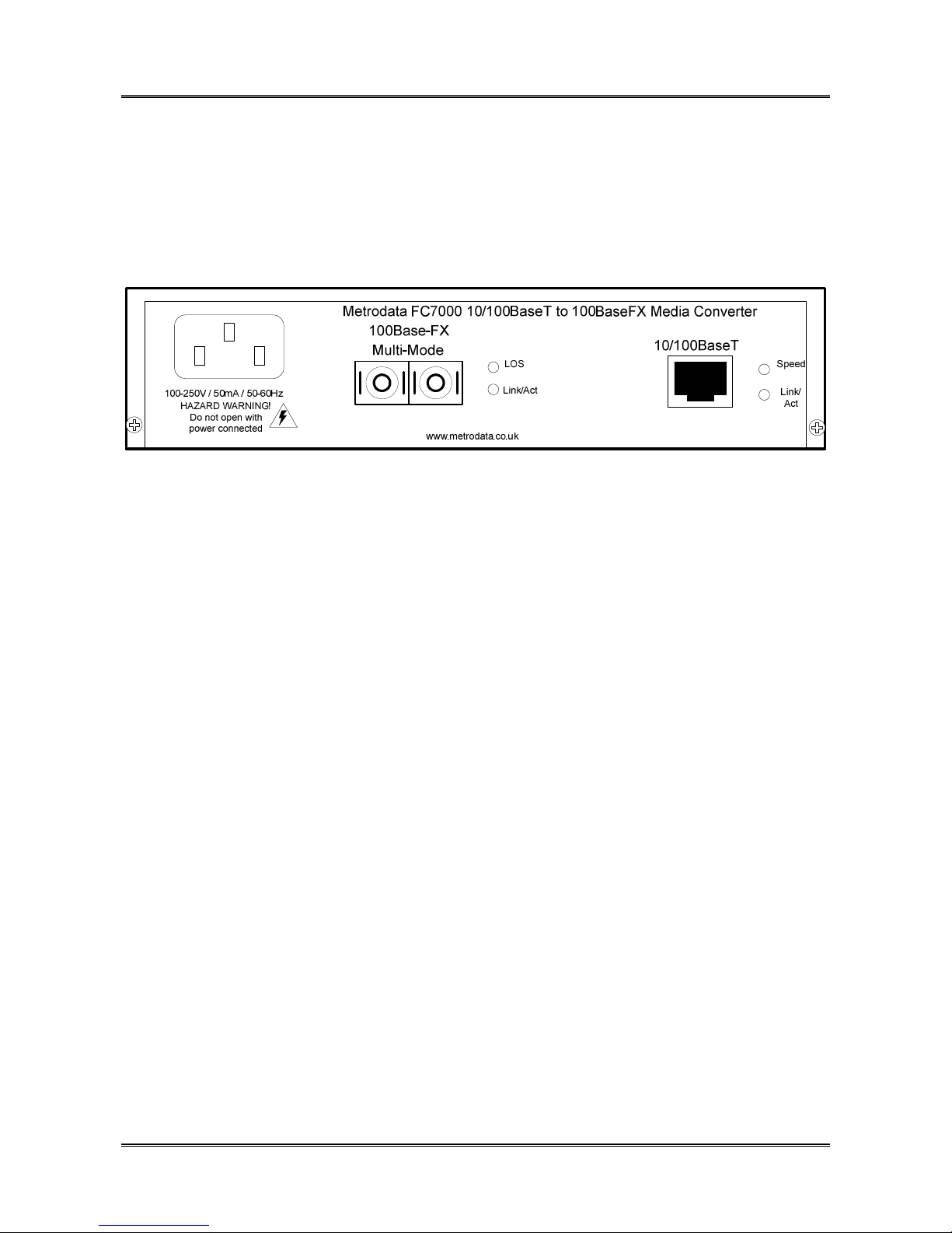
The FC7000 has all connectors on the rear panel for easy access, along with status LEDs
for unit monitoring. The FC7000 unit rear panel is shown below
Figure 3: FC7000 Rear panel
The rear panel has several connectors as described below:
3.1 Power Connector
AC Power to the FC7x00 is supplied via an IEC connector on the rear panel. The FC7x00
has an integral power supply and operates over the range 100 to 250V AC and draws less
than 50mA when operating.
Alternatively, DC power may be specified where the Mains IEC connector is replaced with
a buccaneer type connector for operation over the range
7 to 24V DC
36 to 72V DC
3.2 10/100BaseT RJ45 Port
The FC7x00 presents a single RJ45 port offering a 10/100BaseT twisted pair interface.
The port supports both auto negotiation for speed and duplex configuration as well as auto
MDI/MDIX crossover to simplify cable connections as all connections may be made with a
normal straight through patch cable, removing the need to use cross over cables.
3.3 100BaseFX Port
The FC7x00 has a single fibre port presented as a duplex SC connector. Metrodata offer
three versions, supporting either Multi-Mode, Single Mode Short Haul or Single Mode Long
Haul applications
Page 7
METRODATA LTD FC7000 Media Converter
Installation Guide
76-02-047 Rev A
7 of 12
4 FC7X00 CONFIGURATION
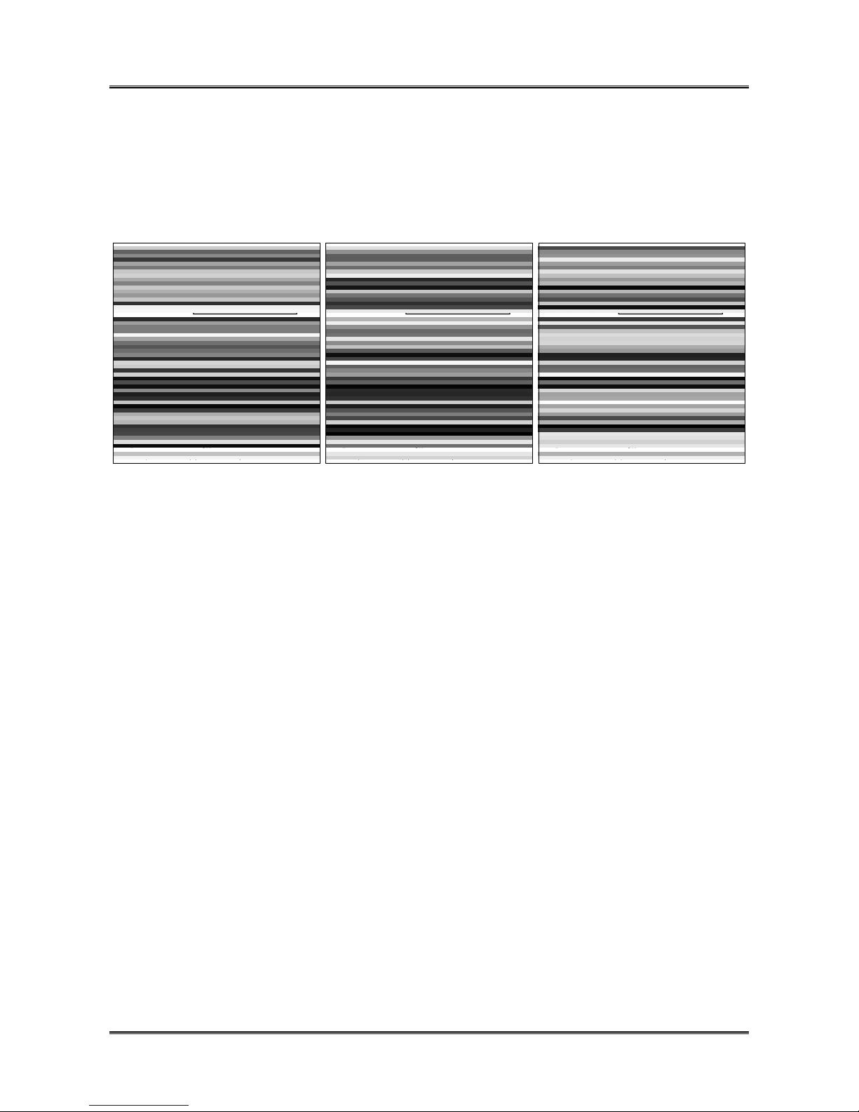
On the underside of the FC7x00 there are bit switches available for configuration of the
unit. The label shown below indicates which fibre interface module is fitted, and also
shows the functions and default positions of the bit switches.
Figure 4: FC7x00 Base Labels
The functions of the bit switches are described below:
4.1 Bit Switch 1: Auto Negotiation
This bit switch controls the auto negotiation operation on the 10/100BaseT twisted pair
interface. When Enabled the port will automatically negotiate with the far end to find the
highest common operation mode. When Auto Negotiation is disabled, the port speed and
duplex modes are configured manually according to switch 2 and 4.
SW1-ON Auto Negotiation Disabled
SW1-OFF Auto Negotiation Enabled
Note, that when the FC7x00 is connected to a non auto negotiating port, the auto
negotiation algorithm can only determine the speed of the link and will always select half
duplex mode. Thus when used with full duplex ports auto negotiation should be disabled,
and the speed and duplex selected manually.
Page 8

METRODATA LTD FC7000 Media Converter
Installation Guide
76-02-047 Rev A
8 of 12
4.2 Bit Switch 2: Speed 100/Speed 10
These two bit switches are used to select the port operating speed manually when auto
negotiation is disabled. This switch is ignored if auto negotiation is enabled.
The possible selections are:
SW-2 ON 100Mbps
SW-2 OFF 10Mbps
4.3 Bit Switch 4: Duplex
This bit switch manually selects the duplex mode for the port when auto negotiation is
disabled. This switch is ignored if auto negotiation is enabled.
SW4-ON Full Duplex
SW4-OFF Half Duplex
4.4 Bit Switch 5: Auto MDI/MDIX
This switch controls the auto crossover function on the twisted pair port. When enabled,
the port will detect the connection and automatically configure itself for either MDI or MDIX
presentation. When auto crossover is enabled, a normal patch cable may be used
whatever devices are being connected. When auto cross is disabled the RJ45 interface
presents a normal switch port with MDIX configuration.
SW5-ON Auto MDI/MDIX Crossover Enabled
SW5-OFF Fixed MDIX interface
Page 9

METRODATA LTD FC7000 Media Converter
Installation Guide
76-02-047 Rev A
9 of 12
4.5 Bit Switch 7: Link State Forwarding
This bit switch controls the Link State Forwarding function. When LSF is enabled, a fault
on one port will propagate to the other port to alert the attached equipment that there is a
fault. A full description of LSF is found in section 6 of this guide. When LSF is disabled, a
fault on one port will not be forwarded.
SW7-ON Link State Forwarding Enabled
SW7_OFF Link State Forwarding Disabled
Page 10
METRODATA LTD FC7000 Media Converter
Installation Guide
76-02-047 Rev A
10 of 12
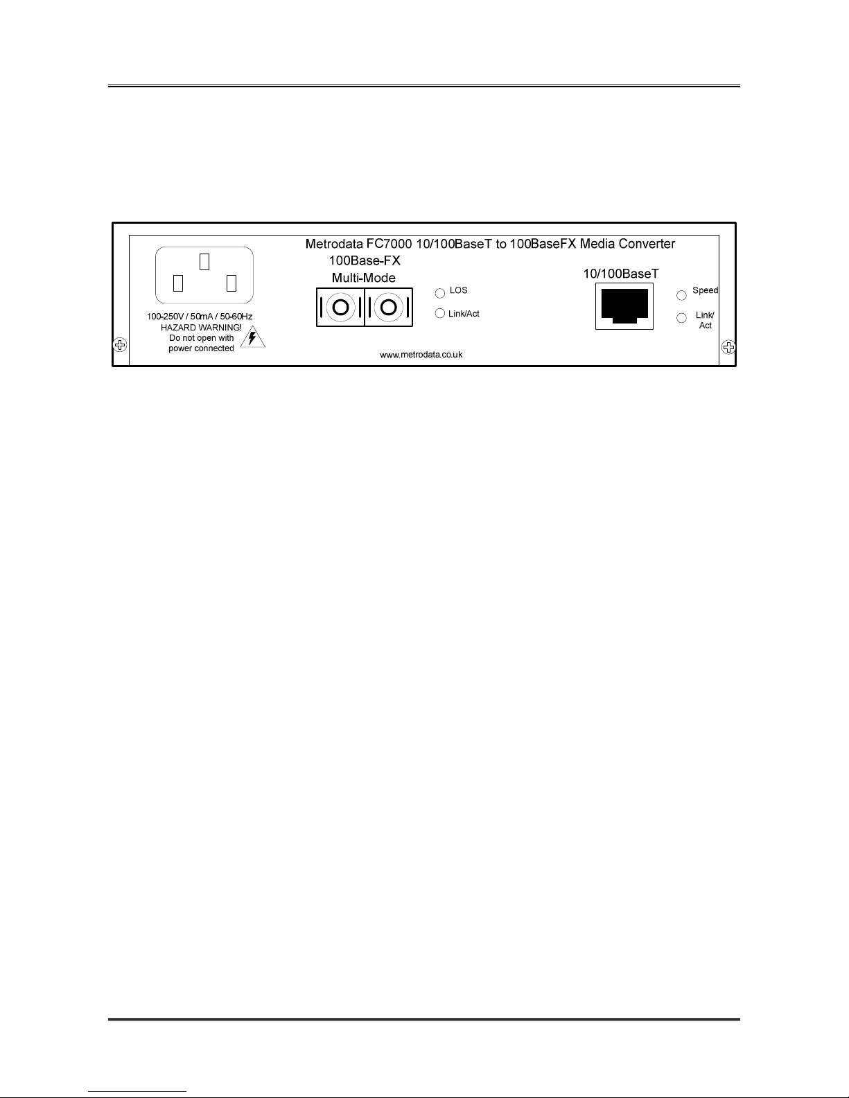
5 FC7X00 STATUS LED INDICATORS
The FC7x00 rear panel has several status LED indicators to display the health and activity
of the unit. The rear panel is shown below:
Figure 5: FC7000 Rear panel
The function of the status LEDs is described below:
5.1 10/100BaseT Link/Act
The green Link / Act LED uses a combination of solid or flashing modes to indicate the
state of the link, and whether there is any activity on the link.
The LED indications are as below:
Link Down LED OFF
10/100M Link Up Green On
10/100M Link Active Green Flash
5.2 10/100BaseT Speed
The green Speed LED indicates the speed of the link
Speed 10M LED OFF
Speed 100M Green ON
Page 11

METRODATA LTD FC7000 Media Converter
Installation Guide
76-02-047 Rev A
11 of 12
5.3 LOS
The LOS LED is a bi-colour LED which indicates the status of the fibre link at the physical
layer. LOS is declared when no signal (light ray) can be detected on the fibre, such as
when the fibre is disconnected or broken.
The states of the LOS LED is as below:
RED Loss of Signal, Fibre Fault
GREEN Fibre Signal Detected
5.4 100Base-FX Fibre Port Link/Act LED
This LED indicates the status of the 100BaseFX Fibre port at layer 2. The LED indicates
the state of the link, as well as activity on the link. The LED displays are as below:
OFF Link Down
GREEN ON Link UP
GREEN Flash Link Up and Active
Page 12
METRODATA LTD FC7000 Media Converter
Installation Guide
76-02-047 Rev A
12 of 12
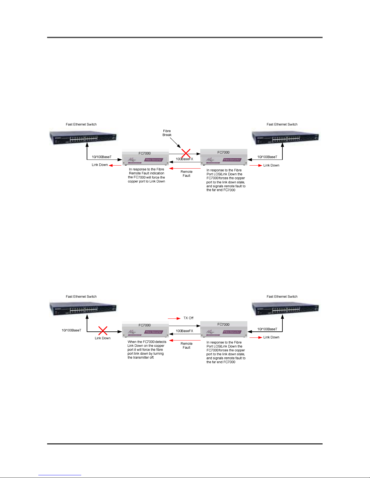
6 LINK STATE FORWARDING
The FC7x00 supports Link State Forwarding (LSF) which will propagate an error through
the network such that devices downstream are made aware of link problems and can take
appropriate action.
6.1 LSF for Fibre Fault
When a fibre fault occurs, one or both FC7000 units will declare LOS and also LINK
DOWN for the fibre port. With LSF enabled, the FC7000 will then forward this fault to the
copper port by forcing it to the LINK DOWN state. Additionally, the Fibre Port will start
transmitting a special remote fault pattern (FEFI). In response to the remote fault indication
received on the fibre port, the FC7000 will also force the copper port LINK DOWN.
When the fibre is restored, the FC7000 will detect signal and declare LINK UP and
immediately cease transmission of the remote fault pattern and re-enable the copper port.
The link will then be re-established end to end.
6.2 LSF for Copper Fault
If a cable is removed, or disconnected from the 10/100BaseT copper port on the FC7000
the device will declare LINK DOWN. In response to this fault, the FC7000 will propagate
the fault to the Fibre Port. To force the fibre link down, the FC7000 will turn the fibre
transmitter off. The remote FC7000 will now detect LOS/LINK DOWN and respond with
copper link down and fibre remote fault.
Again, when the copper port is re-connected the end to end link will re-establish.
 Loading...