

METRObility Optical Systems Delta Class, Twister, M133-13, M133-14, M133-15 User Manual
...Page 1
Installation and User’s Guide
“twister”™
M133
ACT
FD
ACT
LK
PWR
METRO
bility
optical systems
LK
FEF
LB FAIL
LB PASS
100Mbps
“twister”™
Page 2

This publication is protected by the copyright laws of the United States and other countries, with all
rights reserved. No part of this publication may be reproduced, stored in a retrieval system, translated,
transcribed, or transmitted, in any form, or by any means manual, electric, electronic, electromagnetic,
mechanical, chemical, optical or otherwise, without prior explicit written permission of Metrobility Optical
Systems, Inc.
© 2002-2003 Metrobility Optical Systems, Inc. All rights reserved. Printed in USA.
Metrobility Optical Systems, the Metrobility Optical Systems logo, and “twister” are trademarks of
Metrobility Optical Systems, Inc.
The information contained in this document is assumed to be correct and current. The manufacturer is
not responsible for errors or omissions and reserves the right to change specifications at any time
without notice.
This manual covers the following Metrobility
100Mbps Delta Class “twister” models:
M133-13 _______ 100Mbps TX to 100Mbps FX multimode SC
M133-14 _______ 100Mbps TX to 100Mbps FX singlemode SC
M133-15 _______ 100Mbps TX to 100Mbps FX multimode ST
M133-16 _______ 100Mbps TX to 100Mbps FX singlemode ST
M133-17 _______ 100Mbps TX to 100Mbps FX singlemode SC (40km)
M133-1E _______ 100Mbps TX to 100Mbps FX multimode MT-RJ
M133-1J _______ 100Mbps TX to 100Mbps FX singlemode SC (100km)
M133-1K _______ 100Mbps TX to 100Mbps FX multimode LC
M133-1M _______ 100Mbps TX to 100Mbps FX singlemode LC
M133-1X _______ 100Mbps TX to 100Mbps SC bidirectional wavelength
division multiplexed (BWDM) 1550/1310nm
M133-1Y _______ 100Mbps TX to 100Mbps SC BWDM 1310/1550nm
Page 3

Contents
Overview........................................................................................4
Key Features............................................................................4
Installation Guide .........................................................................5
Unpack the “twister” and Accessories ......................................5
Attach the Rubber Feet ............................................................5
Choose an Appropriate Location..............................................5
Set the Switches ......................................................................6
Connect to the Network............................................................8
Apply Power ...........................................................................11
User’s Guide ...............................................................................13
LED Indicators........................................................................13
Link Loss Carry Forward (LLCF)............................................14
Far End Fault (FEF) ...............................................................16
Remote Loopback ..................................................................17
Topology Solution...................................................................19
Technical Specifications.........................................................20
Product Safety, EMC, and Compliance Statements...............22
Warranty and Servicing..........................................................23
Page 4

4 Metrobility 100Mbps Delta Class “twister”
Overview
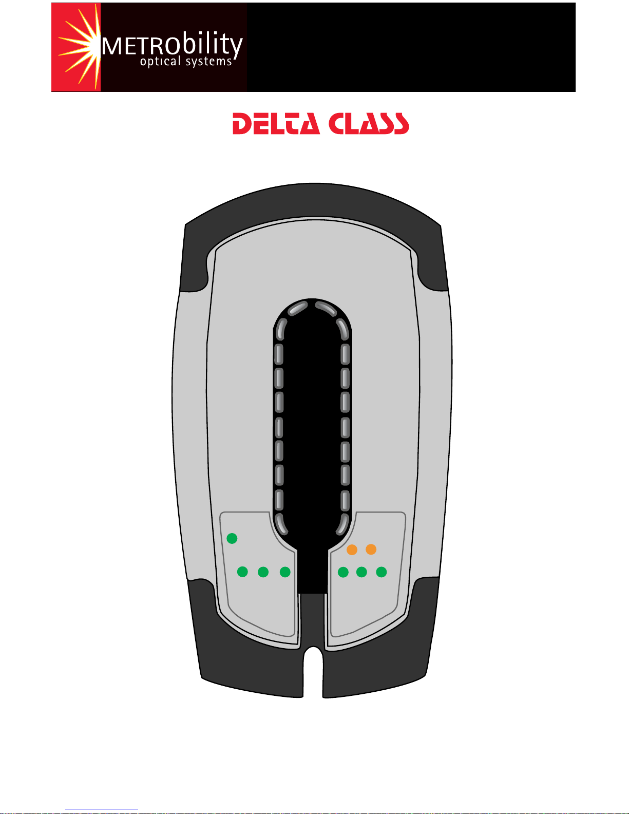
Sleek, compact, and rich in features, Metrobility’s 100Mbps Delta Class
“twister” looks as impressive as it operates. Designed for desktop use in
any modern office, the durable “twister” meets strict US and international
EMC regulations. This innovative device allows you to convert from
copper to fiber, extend copper-based network distances up to 100km,
and test the integrity of the fiber line using remote loopback on the fiber
port. New features include a wall mounting option, automatic MDI-X/MDIII capability, highly visible LEDs on the top, and built-in cable management and protection.
To optimize your Fast Ethernet network, the “twister” provides seamless
operation in full- and half-duplex environments. Full signal restoration
ensures accurate data transmission throughout the network. The “twister”
incorporates both Far End Fault and Link Loss Carry Forward, two
troubleshooting functions to help identify the loss of a remote network
connection.
On select models, bidirectional wavelength division multiplexing (BWDM)
offers an interface that carries two separate channels in different directions through a single strand of fiber. BWDM eliminates the need to
install a second fiber and effectively doubles the fiber capacity on existing fiber cables.
Key Features
• Link Loss Carry Forward
• Far End Fault notification
• Remote fiber loopback to test the entire fiber link
• Auto-negotiation on copper port
• Auto-crossover (i.e., no crossover cables to install or switches to set)
• Convenient LED indicators located on the top for high visibility
• Integral cable management and protection
•Wall mountable
• Far End Fault indicator on the fiber port
•Multiple connectivity options, including BWDM
• Fully compliant with IEEE 802.3 and 802.3u
• Stylish, contemporary design in a durable plastic case
Page 5

Installation Guide 5
Installation Guide
Follow the simple steps outlined in this section to install and start using
the Metrobility 100Mbps Delta Class “twister” media converter.
Unpack the “twister” and
Accessories
Check that the following parts are included in your box:
• 100Mbps Delta Class “twister”
• Power supply
• Power supply cord (North American shipments only)
• Four (4) rubber feet
Your order has been provided with the safest possible packaging, but
shipping damage occasionally does occur. Inspect your order carefully. If
you discover any shipping damage, notify your carrier and follow
instructions for damage and claims. Save the original shipping carton if
return or storage of the unit is necessary.
Attach the Rubber Feet
The “twister” is shipped with four rubber feet located on the black
adhesive strip. To install the rubber feet, first turn the “twister” upsidedown. Peel the feet from the adhesive strip, then attach one foot to each
circular indentation on the unit. This provides an air gap which helps to
cool the unit, and also adds stability for desktop operation.
If you are stacking the “twister” on top of another unit, the rubber feet
must be attached to the bottom of the “twister”.
Choose an Appropriate Location
The “twister” is intended for use in either an office or a residential
environment. The unit must be located within six (6) feet of the AC power
source being used and placed as far away as possible from electrical
noise generating equipment such as copiers, electrostatic printers, and
other motorized equipment. If exposed twisted-pair wiring is used nearby,
the wiring should be routed as far away as possible from power cords
and data cables to minimize interference.
Page 6
6 Metrobility 100Mbps Delta Class “twister”
The unit may be oriented in any manner which allows you to make the
physical connection to the power supply and leaves a minimum of six (6)
inches of space for proper ventilation.
Wall Mounting
The “twister” requires no additional hardware for wall mounting. After
selecting an appropriate place for installation, simply align the 1/4"
keyhole opening on the bottom of the unit to a screw (6-32 maximum
head size) or wall anchor. Once you have it positioned properly, make
sure the device is attached securely.
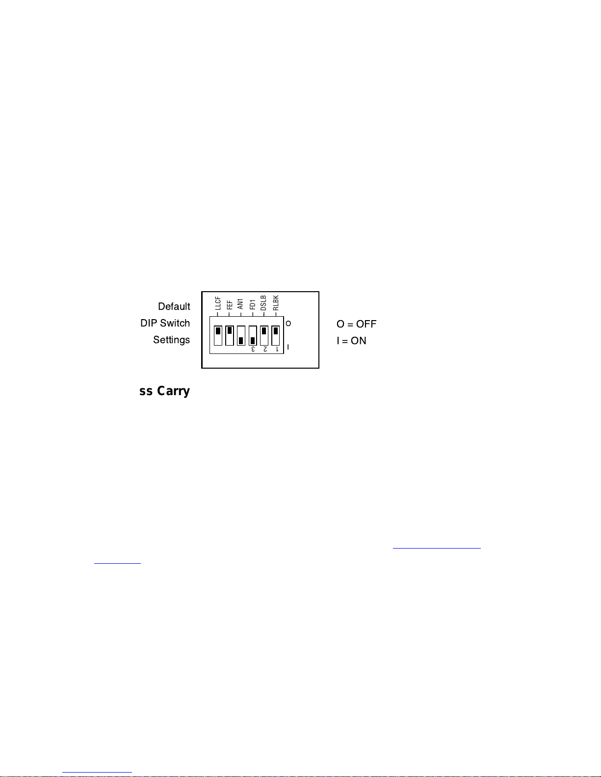
Set the Switches
The “twister” provides a set of six DIP switches located on the back
panel. These switches allow you to select from several modes of
operation. The default settings are shown below.
LLCF
FEF
AN1
FD1
DSLB
RLBK
1 2 3 4 5 6
Link Loss Carry Forward Switch (LLCF)
The “twister” incorporates Link Loss Carry Forward (LLCF) functionality
as an aid in troubleshooting remote connections. When LLCF is enabled,
the loss of inbound link pulses on a port stops the transmission of
outbound link pulses on the
opposite
port. For example, if LLCF is
enabled, the loss of incoming link pulses at
Port 1
will stop the transmis-
sion of link pulses out of
Port 2
. Conversely, if
Port 2
stops receiving link
pulses,
Port 1
will not transmit link pulses.
Link Loss Carry Forward is enabled on both ports when switch LLCF is
ON. The unit is shipped with LLCF disabled. Refer to Link Loss Carry
Forward in the User Guide section of this manual for further details.
Far End Fault Switch (FEF)
The “twister” supports Far End Fault functionality to detect the loss of link
by the remote unit’s fiber port receiver.
FEF is only applicable to the fiber port. When FEF is enabled on a port,
the loss of the inbound link pulses on that port generates an alarm, which
is sent out the port’s transmitter. FEF also enables a port to read the
alarm. To function properly, the FEF setting on both the local and remote
“twister” must be the same.
Page 7

Installation Guide 7
For example, if FEF is enabled on both units and the remote unit’s fiber
receiver (RX) stops detecting link pulses, then its fiber transmitter (TX)
will send an alarm. The local “twister” will receive the alarm and report it
through its fiber port FEF LED, which will turn amber. No alarm will be
issued if FEF is disabled on the remote unit. The FEF LED will not turn
amber if FEF is disabled on the local “twister” because it will not be able
to detect the alarm.
Far End Fault is enabled on Port 2 when switch FEF is ON. The unit is
shipped with FEF disabled. Refer to Far End Fault in the User Guide
section of this manual for more information.
Auto-Negotiation Switch (AN1)
Switch AN1 controls the use of auto-negotiation on the copper port. Autonegotiation determines whether the port operates at half or full duplex.
When AN1 is enabled, the copper port will advertise full duplex capabilities to its connected device, if the duplex switch, FD1, is enabled. The
port will advertise half duplex capabilities if FD1 is disabled. If AN1 is
disabled, the duplex switch will determine the port’s duplex mode. By
default, auto-negotiation is enabled.
Duplex Switch (FD1)
Switch FD1 sets the duplex mode for the copper port when auto-negotiation is disabled. The copper port operates at full duplex when FD1 is
enabled; and it operates at half duplex when FD1 is disabled. If autonegotiation is enabled, the FD1 switch setting will determine whether the
port advertises full or half duplex (refer to Auto-Negotiation above). The
default is set to full duplex enabled.
Copper Port Configuration Table
Use the table below to set the duplex and auto-negotiation DIP
switches to obtain specific modes of operation for the copper port.
noitarugifnoCtroPreppoC1DF1NA
xelpuDlluFNOFFO
xelpuDflaHFFOFFO
xelpuDlluFetaitogeN-otuANONO
xelpuDflaHetaitogeN-otuAFFONO
Disable Loopback Switch (DSLB)
This switch determines the response of the fiber port when it receives the
remote loopback command. If the DSLB switch is enabled, the port will
ignore all remote loopback commands. When the switch is disabled, the
port will permit remote loopback to occur. By default, the response switch
is disabled, which allows remote loopback.
Page 8
8 Metrobility 100Mbps Delta Class “twister”
Remote Loopback Switch (RLBK)
The remote loopback switch allows you to test the fiber connection between
a Metrobility Delta Class “twister” and a remote Metrobility x133 unit.
Enabling the switch sends a loopback request to the remote fiber port. To
run the loopback test properly, the following conditions must be met:
• The remote unit must be a Metrobility x133 standalone converter or
line card.
• The DSLB switch on the remote unit must be disabled.
If the conditions are satisfied, the remote loopback sequence will begin.
The remote fiber port will go into loopback mode. Next, the local “twister”
will generate a test pattern that is sent to the remote unit and then looped
back. The local “twister” will read the returned data to verify proper
transmission. The LB LED on the local “twister” will indicate whether the
test passed (green) or failed (amber). Refer to Remote Loopback for
further information.
If the two conditions for remote loopback are not met, the remote loopback
test will always fail. By default, remote loopback is disabled.
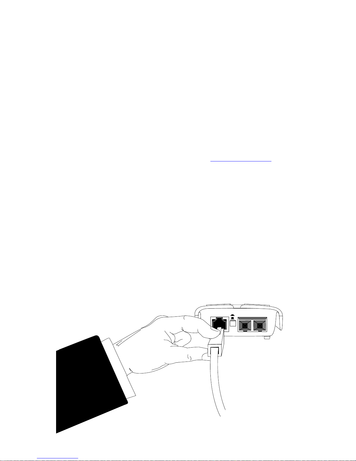
Connect to the Network
The Metrobility 100Mbps Delta Class “twister” offers the ease of plugand-play installation. The overhang extension provides built-in protection
for the two cable connectors.
When making network connections with the Metrobility “twister”, grasp
the end of the cable with your index finger on the top of the connector
and your thumb on the bottom, as shown in the illustration below. For
easier installation, insert the copper cable to the “twister” before connecting the fiber.
II
x
Page 9

Installation Guide 9
RJ-45
Twisted-Pair Connection
The “twister” provides one shielded RJ-45 connector that supports a
maximum segment length of up to 100 meters. Use only Category 5 or
5E UTP/STP cables.
Fiber Optic Connections
• The M133-13, -15, -1E and -1K provide one set of FX multimode SC /
ST / MT-RJ / LC connectors, respectively, and support a maximum
segment length of up to 2km for remote links.
• The M133-14, -16 and -1M provide one set of FX singlemode SC/ST/
LC connectors, respectively, and support a segment length of up to
20km for remote links.
• The M133-17 provides one set of FX singlemode SC connectors and
supports a maximum segment length of up to 40km for remote links.
• The M133-1J provides one set of FX singlemode SC connectors and
supports a maximum segment length of up to 100km for remote links.
Once power is applied to the unit, correct connectivity can be verified via
the link (LK) LEDs if a device is connected to the remote end of the
cable.
LK TX
LK TX
ST
LC
BWDM
SC
MT-RJ
Page 10

10 Metrobility 100Mbps Delta Class “twister”
BWDM Connection
The bidirectional wavelength division multiplexed (BWDM) port provides
one singlemode SC connector that supports a maximum segment length
of 20km. BWDM line cards must always be used in complementary pairs.
That is, a -1X model must be connected to a -1Y. The -1X cards are
designed to transmit data at a wavelength of 1550nm and receive at
1310nm. Correspondingly, the -1Y cards transmit data at 1310nm and
receive at 1550nm.
Metrobility
-1X Model
Metrobility
-1Y Model
up to 20km
Page 11

Installation Guide 11
Apply Power
Power is applied to the “twister” through the desktop power supply. To
apply power, do the following:
1. Connect the power cord (not included with international shipments) to
the AC receptacle on the power supply.
2. Connect the power supply to the DC input power jack located on the
back of the “twister”.
3. The “twister” is designed with built-in cable
management and protection. Turn the unit
upside-down and route the DC power cord
into one of the two channels located on each
side of the unit. See diagram.
4. Plug the power cord into an AC wall outlet.
Upon receiving power, the power (PWR)
LED turns green, and the “twister” automatically goes into operation providing the
appropriate signal translation between
connected network segments.
5. Verify valid connections via
the link (LK) LEDs,
which should be lit.
If an additional
extension cord is
needed to connect the
power supply to the outlet, use the guidelines below. While one end of
the AC power cord can be fitted with a plug standard for the country of
operation, the end that connects to the Metrobility power supply must
have a female plug that fits the following type of AC receptacle:
• AC 115V (North America): Use a UL-listed and CSA-certified cord set
consisting of a minimum of No. 18 AWG, type SVT or SJT threeconductor cord (5 feet maximum length) and a parallel blade grounding-type attachment plug rated 15A, 125V.
• AC 230V (USA): Use a UL-listed cord set consisting of a minimum
No. 18 AWG, type SVT three-conductor cord (15 feet maximum
length) and a Tandem blade grounding-type attachment plug rated
15A, 250V.
Page 12

12 Metrobility 100Mbps Delta Class “twister”
• 240V (outside USA): Use a cord set consisting of a minimum No. 18
AWG cord and grounding-type attachment plug rated 15A, 250V. The
cord set should have the appropriate safety approvals for the country
in which the “twister” is being installed and be marked HAR.
Page 13

User’s Guide 13
User’s Guide
This section contains information regarding the operating features of the
Metrobility 100Mbps Delta Class “twister”.
LED Indicators
The Metrobility 100Mbps Delta Class “twister” provides several LEDs for
the visible verification of unit status and proper functionality. The LEDs
can assist in troubleshooting and with overall network diagnosis and
management.
“twister”™
M133
ACT
FD
ACT
LK
PWR
LK
FEF
LB FAIL
LB PASS
DEL
lebaL
DEL
emaN)sutatS(roloC
noitacidnI
RWPrewop)ydaets(neerg.NOsitinuehT
sDELtroPreppoC
DFxelpud)ydaets(neerg
tI.tilnehwedomxelpud-llufnisitropehT
.tiltonnehwedomxelpud-flahnisi
KLknil)ydaets(neerg.dehsilbatseknilsahtropehttahtseifireV
TCAytivitca)gnihsalf(neerg.atadgniviecersitropehT
sDELtroPrebiF
BL
SSAP
kcabpool
ssap
)ydaets(neerg
.ylreporpkcabdepoolatadtseT:tinUlacoL
.atadtsetkcabpoolgniveceR:tinUetomeR
BL
LIAF
kcabpool
liaf
)ydaets(rebma
.deliaftsetkcabpooletomeR:tinUlacoL
kcabpooletomernisitroP:tinUetomeR
.atadtsetgniviecertontub,edom
KLknil)ydaets(neerg.dehsilbatseknilsahtropehttahtseifireV
FEF
dneraf
tluaf
)ydaets(rebma
rebifetomerehT.detcetedtluafdneraF
ehtmorflangisdilavagniviecertonsitrop
.tinulacol
TCAytivitca)gnihsalf(neerg.atadgniviecersitropehT
Fiber
Port LEDs
Copper
Port LEDs
Page 14

14 Metrobility 100Mbps Delta Class “twister”
Link Loss Carry Forward (LLCF)
The Metrobility Delta Class “twister” incorporates LLCF* for troubleshooting remote connections. When LLCF is enabled, the ports do not transmit a link signal until they receive a link signal from the opposite port.
The diagram below shows a typical network configuration with good link
status using two “twister” units for remote connectivity. Note that LLCF is
enabled as indicated in the diagram below.
Management
Station
Management
Station
Switch/Hub
w/SNMP
Switch/Hub
w/SNMP
twister twister
LED lit = established link LED unlit = no link
LLCF is ON LLCF is ON
Remote
Cable
If a connection breaks, each “twister” will carry that link loss forward to a
switch/hub which generates a trap to a management station. The network administrator can then determine the source of the problem.
Link Loss Carried Forward Link Loss Carried Forward
LED lit = established link LED unlit = no link
Management
Station
Management
Station
Switch/Hub
w/SNMP
Switch/Hub
w/SNMP
twister twister
LLCF is ON LLCF is ON
Broken
Remote
Cable
Link Loss Carried Forward
LED lit = established link LED unlit = no link
Management
Station
Management
Station
Switch/Hub
w/SNMP
Switch/Hub
w/SNMP
twister twister
LLCF is ON LLCF is ON
Broken
Cable
Remote
Cable
* Units are shipped with LLCF disabled.
Page 15

User’s Guide 15
LLCF with Auto-Negotiation
IMPORTANT:
To prevent synchronization problems, we recommend that
you do not enable both LLCF and auto-negotiation at the same time on
the both the local and remote “twister”. Disable one of the functions on
either unit to ensure quick link establishment.
When LLCF and auto-negotiation (AN) are enabled simultaneously on
both the local and remote units, as shown in the following diagram, it
may take a few seconds for the “twister” units to establish link.
local
“twister”
remote
“twister”
LED lit = established link LED unlit = no link
LLCF is ON LLCF is ON
Fiber
Cable
Copper
Cable
Copper
Cable
AN is ON
AN is ON
AN is ON
AN is ON
As connections are created, the “twister” units may enter a situation in
which the LLCF and auto-negotiation functions become synchronized but
slightly out of phase. This will cause continuous up-down link conditions
on all ports. That is, the link (LK) LEDs on the ports will blink on and off.
If the condition lasts more than 10 seconds, reset one of the “twister”
units, or unplug and then reconnect one of the connectors. The links
should be established within a few seconds.
Page 16

16 Metrobility 100Mbps Delta Class “twister”
Far End Fault (FEF)
The Metrobility “twister” is designed with Far End Fault* functionality to
identify the loss of link in the remote unit’s fiber receiver. FEF is not
applicable to the copper port.
Setting FEF on the fiber optic port enables two operations:
1. It allows the fiber
transmitter
to issue a FEF alarm when the fiber
receiver
fails to detect a valid link.
2. It enables the port to read the FEF alarm, so it can activate its FEF
LED.
IMPORTANT:
To function properly, the FEF setting on both the local and
the remote “twister” must be the same.
The diagram below shows a typical network configuration with good link
status using two “twister” units with FEF enabled.
If one of the optical conductors is bad (as shown in the diagram box
below), “twister” B will send a FEF alarm to its link partner on “twister” A.
“twister” A will report the condition through its amber FEF LED and unlit
LK LED.
PC
Remote
Station
Switch/Hub
w/SNMP
Switch/Hub
w/SNMP
twister
A
twister
B
Copper
Copper
Fiber
Cable
LK LED green = established link LK LED unlit = no link
FEF is ON
FEF is ON
LK LED amber= FEF detected
PC
Remote
Station
Switch/Hub
w/SNMP
Switch/Hub
w/SNMP
twister
A
twister
B
FEF Alarm Sent
LK LED green = established link LK LED unlit = no link
Copper
Copper
Broken
Fiber
Conductor
FEF is ON FEF is ON
LK LED amber= FEF detected
In the example described above, if FEF is disabled on “twister” B, the
FEF alarm will not be transmitted to “twister” A. If FEF is disabled on
“twister” A, it will not be able to read the FEF alarm and its link (LK) LED
will remain green.
*Units are shipped with the FEF function disabled.
Page 17

User’s Guide 17
Remote Loopback
The Delta Class “twister” supports remote loopback testing, which is
typically used to verify the integrity of the fiber link to and from a remote
unit. Use this feature to remotely initiate loopback testing from a central
office and to monitor the results without making a trip to the remote site.
Remote loopback is enabled through the DIP switch labeled RLBK on the
local “twister”. When the switch is set, a request for loopback is sent to
the remote fiber port. To run the loopback test properly, the following
conditions must be met:
• The remote unit connected to the fiber port must be a Metrobility
x133. The remote unit may be another “twister” or a line card.
• The disable loopback (DSLB) response switch on the remote unit
must be disabled. DSLB determines whether commands to begin
remote loopback are executed or ignored.
If the two conditions are not met, the remote loopback test will always fail.
If the conditions are satisfied, the remote loopback sequence begins:
• The remote unit goes into loopback mode, in which the fiber port
returns the incoming traffic back to the sender.
• The local “twister” generates a test pattern that is sent to the
remote port and then looped back.
Local Delta Class twister Remote Metrobility x133
Fiber
test
test
RLBK = ON
DSLB = OFF
• The local “twister” reads the returned pattern and checks if there
are any errors or problems.
• The LB LEDs on the local “twister” indicates whether the operation
succeeded (green) or failed (amber). On the remote unit, the LB
PASS LED is green when it receives the test pattern, and the LB
FAIL LED is amber when it does not.
Remote Loopback Time Out
The fiber port is designed to resume normal data transmission within 15
seconds after receiving the remote loopback command. If the RLBK
switch is still enabled on the local “twister” after the time-out period occurs,
the remote port will repeat the loopback sequence. During this transitional
period, when the remote port has reset itself and is no longer looping
back the test pattern, the LB FAIL LED on the local “twister” may briefly
turn amber. For example if the RLBK switch is ON for 40 seconds, the LB
FAIL LED may briefly turn amber after 15 seconds and again after 30.
Page 18

18 Metrobility 100Mbps Delta Class “twister”
If the RLBK switch setting on the local “twister” is changed from ON to
OFF before the remote card resets itself, the LB FAIL LED on the remote
unit may be amber for a few seconds. This is because the remote port
has not timed out and is still in loopback mode waiting to receive test
patterns. The remote port will resume normal operation after the time out
occurs, which will be in less than 15 seconds.
Time Out Indications
DELLIAFBLlacoLDELLIAFBLetomeR
roloC
)sutats(
noitacidnI
roloC
)sutats(
noitacidnI
rebmA
)feirb(
tesersahtropetomeR
gnissapnigebotflesti
eht,revewoh,atad
kcabpooletomer
delbanellitssihctiws
.tinulacolehtno
rebmA
ssel(
51naht
)sdnoces
hctiwskcabpooletomerehT
neebsahtinulacolehtno
tropetomerehttub,delbasid
.teytuodemittonsah
Page 19

User’s Guide 19
Topology Solution
Enterprise Switch
F/O Links
Twisted-pair Links
100Mbps Switch
100Mbps Switch
2km multimode F/O
2km multimode F/O
20km singlemode F/O
Servers with
100Mbps NICs
Metrobility
M133
Metrobility
M133
Metrobility
M133
Metrobility
M133
Enterprise
Metrobility
M133
Page 20

20 Metrobility 100Mbps Delta Class “twister”
Technical Specifications
Network Connections
Twisted-Pair Interface
Connector _____________________Shielded RJ-45, 8-pin modular jack
Impedance ________________________________ 100 Ohms nominal
Signal Level Output (peak differential) ________________ 0.95 to 1.05V
Signal Level Input _____________________________ 200mV minimum
Supported Link Length __________________________________ 100m
Cable Type __________________________ Category 5 or 5E UTP/STP
Multimode Fiber Optic Interface
(M133-13, M133-15, M133-1E, M133-1K)
Connector _________________________________ SC, ST, MT-RJ, LC
Wavelength _________________________________________ 1310nm
RX Input Sensitivity _______________-31 dBm minimum (M133-13, -15)
__________________ -32 dBm minimum (M133-1K)
Output Power ______________________ -20 dBm minimum (M133-1K)
_________________ - 23.5 dBm to -14 dBm (50/125 µm)
________________ -20 dBm to -14 dBm (62.5/125 µm)
Supported Link Length ______________________ up to 2km full duplex
Cable Type ____________________________50/125, 62.5/125 µm F/O
Singlemode Fiber Optic Interface
(M133-14, M133-16, M133-1M)
Connector ________________________________________ SC, ST, LC
Wavelength _________________________________________ 1310nm
RX Input Sensitivity _______________-31 dBm minimum (M133-14, -16)
__________________ -32 dBm minimum (M133-1M)
Output Power ______________________________ -15 dBm to -8 dBm
Supported Link Length _____________________ up to 20km full duplex
Cable Type _____________________________________9/125 µm F/O
Singlemode Fiber Optic Interface — long haul distance support
(M133-17)
Connector ______________________________________________ SC
Wavelength _________________________________________ 1310nm
RX Input Sensitivity __________________________ -34 dBm maximum
Output Power ________________________________ -6 dBm to 0 dBm
Supported Link Length _____________________ up to 40km full duplex
Cable Type _____________________________________9/125 µm F/O
Page 21

User’s Guide 21
Singlemode Fiber Optic Interface — extended long haul distance support
(M133-1J)
Connector ______________________________________________ SC
Wavelength _________________________________________ 1550nm
RX Input Sensitivity ___________________________ -34 dBm minimum
Output Power ________________________________ -5 dBm to 0 dBm
Supported Link Length ____________________ up to 100km full duplex
Cable Type _____________________________________9/125 µm F/O
Singlemode BWDM Fiber Optic Interface
Connector ______________________________________________ SC
RX Input Sensitivity ___________________________ -32 dBm minimum
Output Power ______________________________ -15 dBm to -8 dBm
Supported Link Length _____________________ up to 20km full duplex
Cable Type __________________________ 9/125 µm single-strand F/O
(M133-1X)
TX Wavelength ___________________________________ 1550nm
RX Wavelength___________________________________ 1310nm
(M133-1Y)
TX Wavelength ___________________________________ 1310nm
RX Wavelength___________________________________ 1550nm
Data Rate
Data Rate _________________________________100Mbps full duplex
________________________________ 200Mbps half duplex
Power
AC Input _______________________________ 100-240V AC 50/60 Hz
DC Output _________________________________+ 5V @ 2Amp, 10W
M133 Power Consumption __________________+ 5V @ 0.5Amp, 2.5W
Environmental
Operating Temperature ______________________________ 0° to 50° C
Storage Temperature _____________________________ -25° to 70° C
Relative Humidity _____________________5% to 95% non-condensing
Physical Case _________________ Impact-resistant plastic construction
Dimensions _____________________________ 7" L x 3.75" W x 1.5" H
___________________________17.8 cm x 9.5 cm x 3.8 cm
Weight (including power supply) ___________________ 1.2 lbs, 0.55 kg
Page 22

22 Metrobility 100Mbps Delta Class “twister”
Product Safety, EMC, and
Compliance Statements
This equipment complies with the following requirements:
•UL •CE
• CSA • EN60950 (safety)
• FCC Part 15, Class A • EN55024: 1998 (immunity)
• EN55022 Class A (emissions) • DOC Class A (emissions)
• Class 1 Laser Product • IEC 825-1 Classification
This product shall be handled, stored and disposed of in accordance with
all governing and applicable safety and environmental regulatory agency
requirements.
The following
FCC
and
Industry Canada
compliance information is
applicable to North American customers only.
USA FCC Radio Frequency Interference Statement
This equipment has been tested and found to comply with the limits for a
Class A digital device, pursuant to Part 15 of the FCC Rules. These limits
are designed to provide reasonable protection against harmful interference when the equipment is operated in a commercial environment. This
equipment generates, uses and can radiate radio frequency energy, and
if not installed and used in accordance with the instruction manual, may
cause harmful interference to radio communications. Operation of this
equipment in a residential area is likely to cause harmful interference in
which case the user will be required to correct the interference at his own
expense.
Caution:
Changes or modifications to this equipment not expressly
approved by the party responsible for compliance could void the user’s
authority to operate the equipment.
Canadian Radio Frequency Interference Statement
This Class A digital apparatus meets all requirements of the Canadian
Interference-Causing Equipment Regulations.
Cet appareil numérique de la classe A respecte toutes les exigences du
Réglement sur le matériel brouilleur du Canada.
Page 23

User’s Guide 23
Warranty and Servicing
Three-Year Warranty for the Metrobility 100Mbps “twister”
Metrobility Optical Systems, Inc. warrants that every Metrobility 100Mbps
Delta Class “twister” will be free from defects in material and workmanship for a period of THREE YEARS. This warranty covers the original
user only and is not transferable. Should the unit fail at any time during
this warranty period, Metrobility will, at its sole discretion, replace, repair,
or refund the purchase price of the product. This warranty is limited to
defects in workmanship and materials and does not cover damage from
accident, acts of God, neglect, contamination, misuse or abnormal
conditions of operation or handling, including overvoltage failures caused
by use outside of the product’s specified rating, or normal wear and tear
of mechanical components.
To establish original ownership and provide date of purchase, complete
and return the registration card or register the product online at
www.metrobility.com. If product was not purchased directly from Metrobil-
ity, please provide source, invoice number and date of purchase.
To return a defective product for warranty coverage, contact Metrobility
Customer Service for a return materials authorization (RMA) number.
Send the defective product postage and insurance prepaid to the address provided to you by the Metrobility Technical Support Representative. Failure to properly protect the product during shipping may void this
warranty. The Metrobility RMA number must be clearly on the outside of
the carton to ensure its acceptance.
Metrobility will pay return transportation for product repaired or replaced
in-warranty. Before making any repair not covered by the warranty,
Metrobility will estimate cost and obtain authorization, then invoice for
repair and return transportation. Metrobility reserves the right to charge
for all testing and shipping costs incurred, if test results determine that
the unit is without defect.
This warranty constitutes the buyer’s sole remedy. No other warranties,
such as fitness for a particular purpose, are expressed or implied. Under
no circumstances will Metrobility be liable for any damages incurred by
the use of this product including, but not limited to, lost profits, lost
savings, and incidental or consequential damages arising from the use
of, or inability to use, this product. Authorized resellers are not authorized
to extend any other warranty on Metrobility’s behalf.
Page 24

Product Manuals
The most recent version of this manual is available online at
http://www.metrobility.com/support/manuals.htm
To obtain additional copies of this manual, contact your reseller, or call
1.877.526.2278 or 1.603.880.1833
Product Registration
To register your product, go to
http://www.metrobility.com/support/registration.asp
25 Manchester Street, Merrimack, NH 03054 USA
tel: 1.603.880.1833 • fax: 1.603.594.2887
www.metrobility.com
5660-213313 C
4/03
 Loading...