

Page 1
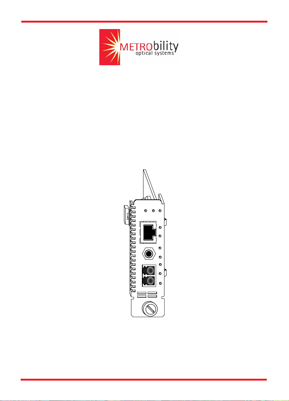
Radiance 10/100 Mbps
Services Line Card
10/100BASE
MAN FD PWR
1
C
O
N
S
O
L
E
RX
2
TX
RX
LK
SPD
LBK
DIS
RX
LK
Installation and User Guide
Model:
R821-1S
Page 2

Radiance 10/100 Mbps Services Line Card
Line Card:
R821-1S ________ 10/100 Mbps RJ-45 to 100 Mbps SFP
Multimode Small Form-Factor Pluggable (SFP) Fiber Optic Transceiver:
O280-M2________ SFP Multimode LC (1310 nm, 17 dB) 2 km, without digital diagnostics
Singlemode SFP Fiber Optic Transceivers:
O281-40 ________ SFP Singlemode LC (1310 nm, 33.5 dB) 40 km
O281-80 ________ SFP Singlemode LC (1550 nm, 33.5 dB) 80 km
O283-20 ________ SFP Singlemode LC (1310 nm, 20.5 dB) 20 km
Bidirectional Wavelength Division Multiplexing (BWDM) SFP Fiber Optic Transceivers:
O383-20-31 _____ SFP BWDM SC (1310 nm/1550 nm, 19 dB) 20 km
O383-20-55 _____ SFP BWDM SC (1550 nm/1310 nm, 19 dB) 20 km
Coarse Wavelength Division Multiplexing (CWDM) SFP Fiber Optic Transceivers:
O483-80-47 _____ SFP CWDM LC (1470 nm, 33 dB) 80 km
O483-80-49 _____ SFP CWDM LC (1490 nm, 33 dB) 80 km
O483-80-51 _____ SFP CWDM LC (1510 nm, 33 dB) 80 km
O483-80-53 _____ SFP CWDM LC (1530 nm, 33 dB) 80 km
O483-80-55 _____ SFP CWDM LC (1550 nm, 33 dB) 80 km
O483-80-57 _____ SFP CWDM LC (1570 nm, 33 dB) 80 km
O483-80-59 _____ SFP CWDM LC (1590 nm, 33 dB) 80 km
O483-80-61 _____ SFP CWDM LC (1610 nm, 33 dB) 80 km
Accessory:
R800-CA ________ Console Cable
This publication is protected by the copyright laws of the United States and other countries, with all rights reserved. No part of
this publication may be reproduced, stored in a retrieval system, translated, transcribed, or transmitted, in any form, or by any
means manual, electric, electronic, electromagnetic, mechanical, chemical, optical or otherwise, without prior explicit written
permission of Metrobility Optical Systems, Inc.
Metrobility, Metrobility Optical Systems, and NetBeacon are registered trademarks, the Metrobility Optical Systems logo and
WebBeacon are trademarks of Metrobility Optical Systems, Inc. All other trademarks are the property of their respective owners.
The information contained in this document is assumed to be correct and current. The manufacturer is not responsible for errors
or omissions and reserves the right to change specifications at any time without notice.
© 2005 Metrobility Optical Systems, Inc. All rights reserved. Printed in USA.
Page 3

Contents
Chapter 1: Overview . . . . . . . . . . . . . . . . . . . . . . . . . . . . . . . . . . . . . .7
Key Features . . . . . . . . . . . . . . . . . . . . . . . . . . . . . . . . . . . . . . . 9
Chapter 2: Installation Guide . . . . . . . . . . . . . . . . . . . . . . . . . . . . . .13
Safety Warning . . . . . . . . . . . . . . . . . . . . . . . . . . . . . . . . . . . . 13
1. Unpack the Line Card . . . . . . . . . . . . . . . . . . . . . . . . . . . . . 13
2. Set the Switches . . . . . . . . . . . . . . . . . . . . . . . . . . . . . . . . . 13
3. Install the SFP Optics . . . . . . . . . . . . . . . . . . . . . . . . . . . . . 14
1
Copper Port . . . . . . . . . . . . . . . . . . . . . . . . . . . . . . . . . . 9
Fiber Port . . . . . . . . . . . . . . . . . . . . . . . . . . . . . . . . . . . . 9
Hardware . . . . . . . . . . . . . . . . . . . . . . . . . . . . . . . . . . . . 9
Software . . . . . . . . . . . . . . . . . . . . . . . . . . . . . . . . . . . . 10
DIP Switches . . . . . . . . . . . . . . . . . . . . . . . . . . . . . . . . 14
4. Install the Line Card . . . . . . . . . . . . . . . . . . . . . . . . . . . . . . 15
5. Connect to the Network . . . . . . . . . . . . . . . . . . . . . . . . . . . 16
Chapter 3: Management . . . . . . . . . . . . . . . . . . . . . . . . . . . . . . . . . .21
Default Software Settings . . . . . . . . . . . . . . . . . . . . . . . . . . . . 21
Managed Objects . . . . . . . . . . . . . . . . . . . . . . . . . . . . . . . . . . . 22
MIB-II . . . . . . . . . . . . . . . . . . . . . . . . . . . . . . . . . . . . . . 22
Enterprise-Specific Objects . . . . . . . . . . . . . . . . . . . . . 23
Admin Only SNMP Objects . . . . . . . . . . . . . . . . . . . . . 23
Remote Management Statistics . . . . . . . . . . . . . . . . . . . . . . . 24
Setting a Secure Management Channel . . . . . . . . . . . . . . . . 25
Software Settings . . . . . . . . . . . . . . . . . . . . . . . . . . . . . . . . . . 27
IP Addressing Management . . . . . . . . . . . . . . . . . . . . . 27
Copper Line Quality (CLQ) Tester . . . . . . . . . . . . . . . . 29
Far End Fault . . . . . . . . . . . . . . . . . . . . . . . . . . . . . . . . 29
Flow Control . . . . . . . . . . . . . . . . . . . . . . . . . . . . . . . . . 29
Contents
Page 4

2
ICMP . . . . . . . . . . . . . . . . . . . . . . . . . . . . . . . . . . . . . .30
Loopback Modes . . . . . . . . . . . . . . . . . . . . . . . . . . . . .31
Port Management . . . . . . . . . . . . . . . . . . . . . . . . . . . . . 34
Port State . . . . . . . . . . . . . . . . . . . . . . . . . . . . . . . . . . .35
Rate Limiting . . . . . . . . . . . . . . . . . . . . . . . . . . . . . . . .35
Traffic Prioritization . . . . . . . . . . . . . . . . . . . . . . . . . . .36
VLAN Tagging . . . . . . . . . . . . . . . . . . . . . . . . . . . . . . .42
Sensors . . . . . . . . . . . . . . . . . . . . . . . . . . . . . . . . . . . . . . . . . .49
Environmental Sensors . . . . . . . . . . . . . . . . . . . . . . . . 49
Upgrading the Operating System Software . . . . . . . . . . . . . 49
Chapter 4: CLI Commands . . . . . . . . . . . . . . . . . . . . . . . . . . . . . . . 51
Notation Conventions . . . . . . . . . . . . . . . . . . . . . . . . . . . . . . .51
Complete List of Commands . . . . . . . . . . . . . . . . . . . . . . . . . 52
User Commands . . . . . . . . . . . . . . . . . . . . . . . . . . . . .52
Administrator Commands . . . . . . . . . . . . . . . . . . . . . . . 53
Root Commands . . . . . . . . . . . . . . . . . . . . . . . . . . . . .54
Clear Commands . . . . . . . . . . . . . . . . . . . . . . . . . . . . . . . . . . . 55
clear l2controlprotocol . . . . . . . . . . . . . . . . . . . . . . . . . 55
clear mgmtvlan . . . . . . . . . . . . . . . . . . . . . . . . . . . . . . .55
clear radiusserver . . . . . . . . . . . . . . . . . . . . . . . . . . . . . 55
clear snmpuser . . . . . . . . . . . . . . . . . . . . . . . . . . . . . . . 55
clear trapdestination . . . . . . . . . . . . . . . . . . . . . . . . . . .55
clear username . . . . . . . . . . . . . . . . . . . . . . . . . . . . . .56
clear uservlan . . . . . . . . . . . . . . . . . . . . . . . . . . . . . . . .56
System Commands . . . . . . . . . . . . . . . . . . . . . . . . . . . . . . . . . 56
arp . . . . . . . . . . . . . . . . . . . . . . . . . . . . . . . . . . . . . . . . 56
change password . . . . . . . . . . . . . . . . . . . . . . . . . . . . . 57
download . . . . . . . . . . . . . . . . . . . . . . . . . . . . . . . . . . .57
exit . . . . . . . . . . . . . . . . . . . . . . . . . . . . . . . . . . . . . . . . 58
help . . . . . . . . . . . . . . . . . . . . . . . . . . . . . . . . . . . . . . .58
logout . . . . . . . . . . . . . . . . . . . . . . . . . . . . . . . . . . . . . .58
ping . . . . . . . . . . . . . . . . . . . . . . . . . . . . . . . . . . . . . . .58
reset . . . . . . . . . . . . . . . . . . . . . . . . . . . . . . . . . . . . . . .59
run config . . . . . . . . . . . . . . . . . . . . . . . . . . . . . . . . . . .59
Radiance 10/100 Mbps Services Line Card
Page 5

3
Set Commands . . . . . . . . . . . . . . . . . . . . . . . . . . . . . . . . . . . . 60
set console . . . . . . . . . . . . . . . . . . . . . . . . . . . . . . . . . . 60
set dhcp . . . . . . . . . . . . . . . . . . . . . . . . . . . . . . . . . . . . 60
set download . . . . . . . . . . . . . . . . . . . . . . . . . . . . . . . . 60
set dscp . . . . . . . . . . . . . . . . . . . . . . . . . . . . . . . . . . . . 61
set fpga . . . . . . . . . . . . . . . . . . . . . . . . . . . . . . . . . . . . 61
set freeform . . . . . . . . . . . . . . . . . . . . . . . . . . . . . . . . . 61
set icmp . . . . . . . . . . . . . . . . . . . . . . . . . . . . . . . . . . . . 62
set ip . . . . . . . . . . . . . . . . . . . . . . . . . . . . . . . . . . . . . . 62
set l2controlprotocol . . . . . . . . . . . . . . . . . . . . . . . . . . . 62
set l3capability . . . . . . . . . . . . . . . . . . . . . . . . . . . . . . . 63
set logicalservicesloopback . . . . . . . . . . . . . . . . . . . . . 63
set loopback . . . . . . . . . . . . . . . . . . . . . . . . . . . . . . . . . 63
set mgmtvlan . . . . . . . . . . . . . . . . . . . . . . . . . . . . . . . . 64
set oamcontrol . . . . . . . . . . . . . . . . . . . . . . . . . . . . . . . 64
set oamerrframe . . . . . . . . . . . . . . . . . . . . . . . . . . . . . . 64
set oamerrframeperiod . . . . . . . . . . . . . . . . . . . . . . . . . 65
set oamerrframesecs . . . . . . . . . . . . . . . . . . . . . . . . . . 65
set oamerrsymperiod . . . . . . . . . . . . . . . . . . . . . . . . . . 66
set oamloopback . . . . . . . . . . . . . . . . . . . . . . . . . . . . . 66
set os . . . . . . . . . . . . . . . . . . . . . . . . . . . . . . . . . . . . . . 67
set pbits . . . . . . . . . . . . . . . . . . . . . . . . . . . . . . . . . . . . 67
set port . . . . . . . . . . . . . . . . . . . . . . . . . . . . . . . . . . . . . 67
set precedence . . . . . . . . . . . . . . . . . . . . . . . . . . . . . . 68
set priority . . . . . . . . . . . . . . . . . . . . . . . . . . . . . . . . . . 68
set pvid . . . . . . . . . . . . . . . . . . . . . . . . . . . . . . . . . . . . . 69
set qinq . . . . . . . . . . . . . . . . . . . . . . . . . . . . . . . . . . . . 69
set radiusauthentication . . . . . . . . . . . . . . . . . . . . . . . . 70
set radiusretransmit . . . . . . . . . . . . . . . . . . . . . . . . . . . 70
set radiusserver . . . . . . . . . . . . . . . . . . . . . . . . . . . . . . 70
set radiustimeout . . . . . . . . . . . . . . . . . . . . . . . . . . . . . 70
set ratelimit . . . . . . . . . . . . . . . . . . . . . . . . . . . . . . . . . . 71
set snmpcommunity . . . . . . . . . . . . . . . . . . . . . . . . . . . 71
set snmpuser . . . . . . . . . . . . . . . . . . . . . . . . . . . . . . . . 71
set snmpv1v2 . . . . . . . . . . . . . . . . . . . . . . . . . . . . . . . . 72
set switch . . . . . . . . . . . . . . . . . . . . . . . . . . . . . . . . . . . 72
set systeminformation . . . . . . . . . . . . . . . . . . . . . . . . . 72
Contents
Page 6

4
set trapcontrol . . . . . . . . . . . . . . . . . . . . . . . . . . . . . . .73
set trapdestination . . . . . . . . . . . . . . . . . . . . . . . . . . . .73
set username . . . . . . . . . . . . . . . . . . . . . . . . . . . . . . . .74
set uservlan . . . . . . . . . . . . . . . . . . . . . . . . . . . . . . . . .74
Show Commands . . . . . . . . . . . . . . . . . . . . . . . . . . . . . . . . . .75
show cablestatus . . . . . . . . . . . . . . . . . . . . . . . . . . . . . 75
show console . . . . . . . . . . . . . . . . . . . . . . . . . . . . . . . .75
show dhcp . . . . . . . . . . . . . . . . . . . . . . . . . . . . . . . . . . 75
show download . . . . . . . . . . . . . . . . . . . . . . . . . . . . . .76
show fpga . . . . . . . . . . . . . . . . . . . . . . . . . . . . . . . . . . .76
show icmp . . . . . . . . . . . . . . . . . . . . . . . . . . . . . . . . . .76
show ip . . . . . . . . . . . . . . . . . . . . . . . . . . . . . . . . . . . . . 77
show l2controlprotocol . . . . . . . . . . . . . . . . . . . . . . . . .77
show l3capability . . . . . . . . . . . . . . . . . . . . . . . . . . . . . 78
show logicalservicesloopback . . . . . . . . . . . . . . . . . . . 78
show mgmtvlan . . . . . . . . . . . . . . . . . . . . . . . . . . . . . .78
show oamcontrol . . . . . . . . . . . . . . . . . . . . . . . . . . . . . 79
show oameventlog . . . . . . . . . . . . . . . . . . . . . . . . . . . .80
show oamevents . . . . . . . . . . . . . . . . . . . . . . . . . . . . .82
show oamloopback . . . . . . . . . . . . . . . . . . . . . . . . . . .83
show oampeer . . . . . . . . . . . . . . . . . . . . . . . . . . . . . . . 84
show oamstatistics . . . . . . . . . . . . . . . . . . . . . . . . . . . . 85
show os . . . . . . . . . . . . . . . . . . . . . . . . . . . . . . . . . . . . 86
show port . . . . . . . . . . . . . . . . . . . . . . . . . . . . . . . . . . . 86
show portstatistics . . . . . . . . . . . . . . . . . . . . . . . . . . . .88
show pvid . . . . . . . . . . . . . . . . . . . . . . . . . . . . . . . . . . .89
show radius . . . . . . . . . . . . . . . . . . . . . . . . . . . . . . . . . 90
show ratelimit . . . . . . . . . . . . . . . . . . . . . . . . . . . . . . . .90
show rmonportstatistics . . . . . . . . . . . . . . . . . . . . . . . . 90
show sensors . . . . . . . . . . . . . . . . . . . . . . . . . . . . . . . .91
show serviceclasses . . . . . . . . . . . . . . . . . . . . . . . . . .92
show snmpcommunity . . . . . . . . . . . . . . . . . . . . . . . . . 93
show snmpuser . . . . . . . . . . . . . . . . . . . . . . . . . . . . . . 93
show snmpv1v2 . . . . . . . . . . . . . . . . . . . . . . . . . . . . . .94
show switch . . . . . . . . . . . . . . . . . . . . . . . . . . . . . . . . .94
show systeminfo . . . . . . . . . . . . . . . . . . . . . . . . . . . . . . 94
show trapcontrol . . . . . . . . . . . . . . . . . . . . . . . . . . . . . .95
Radiance 10/100 Mbps Services Line Card
Page 7

show trapdestinations . . . . . . . . . . . . . . . . . . . . . . . . . 95
show usernames . . . . . . . . . . . . . . . . . . . . . . . . . . . . . 96
show uservlan . . . . . . . . . . . . . . . . . . . . . . . . . . . . . . . 96
Chapter 5: User Guide . . . . . . . . . . . . . . . . . . . . . . . . . . . . . . . . . . .97
LED Indicators . . . . . . . . . . . . . . . . . . . . . . . . . . . . . . . . . . . . . 97
Default Hardware Switch Settings . . . . . . . . . . . . . . . . . . . . . 98
Link Loss Return (LLR) . . . . . . . . . . . . . . . . . . . . . . . . . . . . . . 98
Link Loss Carry Forward (LLCF) . . . . . . . . . . . . . . . . . . . . . 100
Traps . . . . . . . . . . . . . . . . . . . . . . . . . . . . . . . . . . . . . . . . . . . . 101
Changing the SFP Transceiver . . . . . . . . . . . . . . . . . . . . . . 102
Topology Solutions . . . . . . . . . . . . . . . . . . . . . . . . . . . . . . . . 103
Standards-Based Multi-Service Delivery . . . . . . . . . . 103
Basic Remote Management as a NID . . . . . . . . . . . . 103
802.3ah-Based Enhanced Remote Management . . . 104
Future 802.3ah-Based Remote Management . . . . . . 104
5
RADIUS Reset . . . . . . . . . . . . . . . . . . . . . . . . . . . . . . . . . . . . 105
Technical Specifications . . . . . . . . . . . . . . . . . . . . . . . . . . . 105
Abbreviations and Acronyms . . . . . . . . . . . . . . . . . . . . . . . 108
Product Safety and Compliance Statements . . . . . . . . . . . 111
Warranty and Servicing . . . . . . . . . . . . . . . . . . . . . . . . . . . . 114
Technical Support . . . . . . . . . . . . . . . . . . . . . . . . . . . . . . . . . 115
Chapter 6: Error Messages . . . . . . . . . . . . . . . . . . . . . . . . . . . . . . .117
Contents
Page 8

6
Radiance 10/100 Mbps Services Line Card
Page 9

Chapter 1: Overview
Designed to support the new IEEE 802.3ah standard, Metrobility’s
Radiance R821 10/100 Mbps Services Line Card is a manageable twoport copper-to-fiber device capable of remote communications with an
off-site unit. A third console port provides a connection for direct
management of the R821. Using an in-band management channel, two
Radiance services line cards in a back-to-back configuration can
communicate without a separate IP address at the remote end. Because
an IP address is not needed at every access point, this solution ideally
suits large metro access service deployments.
When paired with Metrobility’s NetBeacon
services line card provides the highest level of manageability with a userfriendly graphical interface. NetBeacon delivers non-intrusive RMON
Group 1 statistics, errored symbol and frame event notifications, and
real-time information on power and temperature, along with Dying Gasp
capabilities.
®
Element Manager, the
7
Other advanced management features and diagnostics include Metrobility’s patent-pending Logical Services Loopback (LSL), rate limiting,
traffic prioritization into four service class levels, Q-in-Q double tagging,
PVID support, built-in copper line quality (CLQ) testing on the copper
port, integral temperature and transmit/receive optical power monitoring
on the fiber port, Link Loss Carry Forward (LLCF), Link Loss Return
(LLR), and Far End Fault (FEF). Rate limiting of user data allows control
over traffic speed and volume, thus maximizing bandwidth efficiency.
LSL, CLQ, LLCF, LLR, and FEF assist in testing and troubleshooting
remote connections.
Additional features include management access control which protects
the system and network connections from denial of service attacks from
the user’s network. By default, management access control automatically
discards unauthorized traffic received over the access port, making the
device impervious to all traffic conditions and traffic patterns. Access
control is also provided by reserving the 0x000 VLAN for use with
management. This management VLAN can be made unavailable to
users by changing the VLAN ID.
Overview
Page 10
8
Two versions of the operational software, the FPGA firmware, and
configuration files can be stored on the services line card. New
embedded software can be downloaded easily in the field as upgrades
become available.
The 10/100 Mbps services line card can be managed as an independent
network interface device (NID) with its own IP address. As a NID at the
CPE demarcation point, the services line card responds to SNMP
requests addressed to unicast and subnet broadcast addresses by delivering information on its health and status as well as its network
connection. SNMP provides Internet-standard management and can be
used for surveillance and fault management.
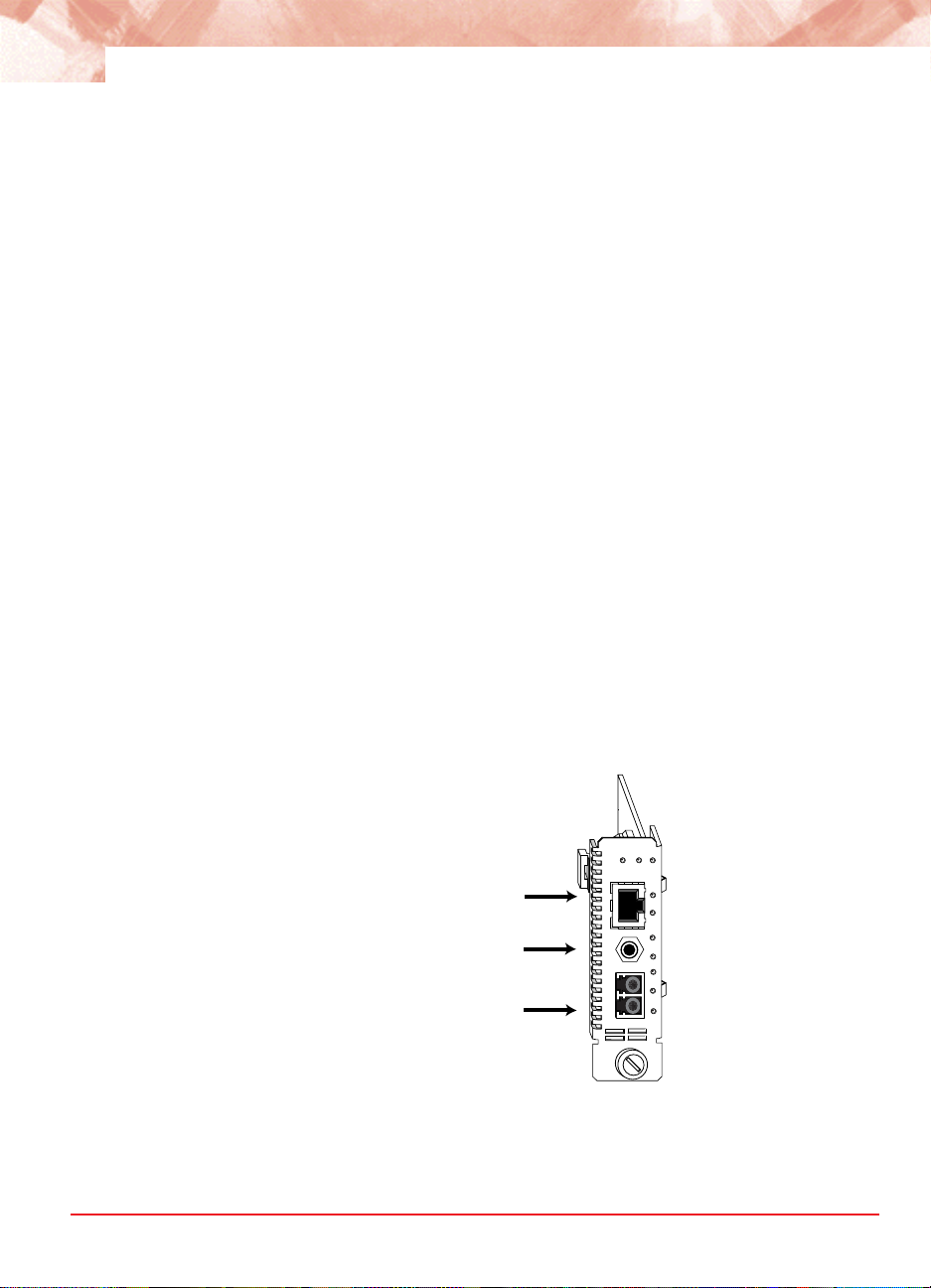
The versatile R821-1S provides a 10/100BASE-T port (Port 1) and a
small form-factor pluggable (SFP) port (Port 2) with numerous
wavelength and distance options. Typically, Port 1 is designated as the
access port and Port 2 as the network port. To simplify device configuration, a third console port is provided for direct access to the services
line card’s management agent.
Both Ethernet interfaces on the services line card support VLAN doubletagging, baby giant frames (up to 1532 bytes untagged and 1536 bytes
tagged), and auto-negotiation. When auto-negotiation is enabled, the
copper port auto-detects MDI-II/MDI-X
1
. Both ports also support flow
control (forced collisions in half duplex and PAUSE frames in full duplex).
1.When forcing 10 or 100 Mbps, a crossover cable may be needed.
Radiance 10/100 Mbps Services Line Card
Port 1
Port 0
(Console Port)
Port 2
10/100BASE
MAN FD PWR
1
C
O
N
S
O
L
E
RX
2
TX
R821-1S
RX
LK
SPD
LBK
DIS
RX
LK
Page 11

Key Features
Copper Port
The Radiance services line card provides the following key features:
10/100 Mbps support.
•
Auto-negotiation or manual duplex and speed selection.
•
Automatic MDI-II/MDI-X conversion when auto-negotiation is enabled.
•
•
Half- and full-duplex flow control.
•
Link Loss Return (LLR) and Link Loss Carry Forward (LLCF) to aid in
troubleshooting.
9
Fiber Port
Hardware
Small form-factor pluggable (SFP) transceivers with support for
•
distances up to 80 km.
•
Support for bidirectional wavelength division multiplexing (BWDM) with
SC connectors and 1550/1310 nm wavelengths.
•
Support for coarse wavelength division multiplexing (CWDM) with
wavelengths from 1470 to 1610 nm.
Built-in optical power and temperature meters that enables proactive
•
maintenance by eliminating the need to disable the fiber link for testing.
•
Link Loss Return (LLR) with Auto-Recovery, Link Loss Carry Forward
(LLCF), and Far End Fault (FEF) to aid in troubleshooting.
Flow control support.
•
Hot swappable board and optics.
•
•
Copper to fiber media conversion.
•
Compliance with applicable sections of IEEE 802.3-2002.
•
Full signal retiming, reshaping, and reamplification (3 Rs).
•
Supports a maximum transmission unit size of 1536 bytes for all
frames.
Transparency to user data traffic, including single and double VLAN-
•
tagged Ethernet frames.
•
Console port for direct device communication.
Overview
Page 12

10
Software
802.3ah OAM support for remote management including:
•
•
Loopback
•
Events
•
Dying Gasp
•
Active or passive modes
•
802.3ah with Metrobility vendor extensions for in-band management.
Remote Quality of Line (QoL) Monitoring (RMON) Group 1 statistics.
•
Real-time monitoring of services line card’s temperature and power.
•
Logical Services Loopback functionality to test non-intrusively for
•
proper connectivity and link integrity.
•
Independent rate limiting on each port.
•
Port interface statistics.
•
Far End Fault detection and notification.
Manageable with Metrobility’s NetBeacon and WebBeacon™ element
•
management software.
•
Interoperable with Metrobility’s SNMP, CLI, TFTP, and telnet access
mechanisms.
•
Compatibility with industry-standard SNMP-based management applications.
Ability to accept and process ARP messages, and respond to ARP
•
requests and replies.
•
Storage for two versions of the operating system and FPGA firmware
as well as two separate configuration files.
Static and dynamic ARP entry provisioning, and the ability to use ARP
•
to resolve IP-to-MAC associations when static associations are
unavailable.
Ping support for network path connectivity testing.
•
Field-programmable for upgrading management software.
•
DHCP client support.
•
A unique unicast MAC address for Logical Services Loopback.
•
Radiance 10/100 Mbps Services Line Card
Page 13

Support for SNMPv1 and SNMPv2c community based profiles and
•
views for read-only, read-write, and administrative access.
•
SNMPv3 support for increased network management security.
Provides user authentication and authorization along with data
encryption.
Transparent MAC-layer forwarding and filtering. (No Spanning Tree)
•
•
Ability to stack and unstack VLAN tags based on the bridge port over
which an Ethernet frame is received or transmitted. (Q-in-Q VLAN
tagging.)
Static ARP and IP address entries.
•
Class of Service (CoS) using four priority queues.
•
•
Traffic prioritization based on p-bits in the VLAN header, DSCP bits in
IP frames, or the default port priority.
•
PVID tagging.
Traffic filtering and forwarding to provide access control security.
•
Copper line quality (CLQ) diagnostic tester that identifies various faults
•
(open circuit, short circuit, impedance mismatch) and indicates the
distance to the fault from the device.
11
•
Support for 16 user VLANs and one management VLAN.
Management support for up to two remote units off each port if the
•
services line card is under proxy management via the R502-M.
• RADIUS client support to protect sensitive network information by
restricting access to authorized users only.
Overview
Page 14

12
Radiance 10/100 Mbps Services Line Card
Page 15

Chapter 2: Installation Guide
Safety Warning
Electrostatic Discharge Warning
Electrostatic discharge precautions should be taken when handling any
!
line card. Proper grounding is recommended (i.e., wear a wrist strap).
1. Unpack the Line Card
Your order has been provided with the safest possible packaging, but
shipping damage does occasionally occur. Inspect your line card
carefully. If you discover any shipping damage, notify your carrier and
follow their instructions for damage and claims. Save the original
shipping carton if return or storage of the card is necessary.
13
2. Set the Switches
A bank of six DIP switches is located on the back of the card. These
switches allow you to select from several modes of operation that only
affect the access port (Port 1). Functional switches are clearly marked on
the card’s circuit board. Refer to the following table for the proper setting
of the DIP switches.
When setting DIP switches, the UP position is when the lever of the DIP
switch is pushed away from the circuit board. The DOWN position is
when the lever is pushed toward the board.
Default Switch Settings
UP
DOWN
12345
SPD1
AN1
DUP1
6
Installation Guide
Page 16

14
Table 1: DIP Switches
Switch
Label
AN1
SPD1
DUP1
Position Description
UP (default)
DOWN
UP (default) Port 1 is set to 100 Mbps when AN1 is disabled.
DOWN Port 1 is set to 10 Mbps when AN1 is disabled.
UP (default) Port 1 is set to full duplex when AN1 is disabled.
DOWN Port 1 is set to half duplex when AN1 is disabled.
Auto-negotiation is enabled. Port 1 advertises 10/100
Mbps half/full duplex capability to its link partner.
Auto-negotiation is disabled. The SPD1 and DUP1
switches determine the speed and duplex for Port 1.
DIP Switches Auto-Negotiation (AN1)
AN1 is the auto-negotiation switch for Port 1. When auto-negotiation is
enabled, the port advertises 10/100 Mbps and half/full duplex capability
to its link partner. When auto-negotiation is disabled, the speed and
duplex for Port 1 are set through the SPD1 and DUP1 switches.
Note: Speed and duplex are dependent upon auto-negotiation. If AN1 is
enabled, the SPD1 and DUP1 switches will be ignored.
Speed (SPD1)
The speed switch applies to Port 1 and is effective only when autonegotiation (AN1) is disabled. Port 1 is set to 100 Mbps when SPD1 is
up, and 10 Mbps when SPD1 is down.
Duplex (DUP1)
The duplex switch applies to Port 1 and is effective only when autonegotiation (AN1) is disabled. Port 1 is set to full duplex when DUP1 is
up, and half duplex when DUP1 is down.
3. Install the SFP Optics
The R821-1S requires one small form-factor pluggable (SFP) optic.
Optics are shipped separately.
Radiance 10/100 Mbps Services Line Card
Page 17
15
Before installing the SFP module, make sure the bail latch is closed, as
shown below. Do NOT open the bail.
SFP
CLOSED
BAIL LATCH
POSITION
SFP
DO NOT
OPEN
BAIL LATCH
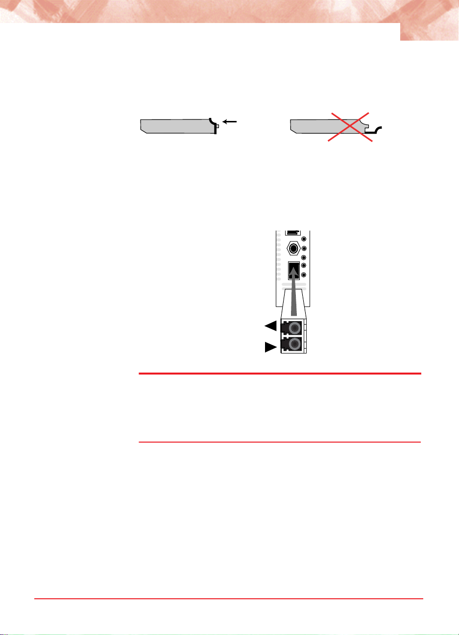
To install the optics, align the SFP module so the receiver (▲) is
positioned above the transmitter (▼). For a BWDM module, align it so the
visible part of the circuit board located at the back of the module is to the
right. The SFP’s circuit board should be on the same side as the LEDs.
Slide the module into the empty slot. Push the SFP firmly in place.
SPD
C
O
LBK
N
S
O
DIS
L
E
RX
2LKRX
TX
LK
RXTX
Important: The Radiance services line card is designed and tested to
operate using only Metrobility-supplied SFP transceivers. Safety, performance, and reliability are guaranteed only when Metrobility transceivers
are used. Installing unspecified parts may damage the product and
will void the unit’s warranty.
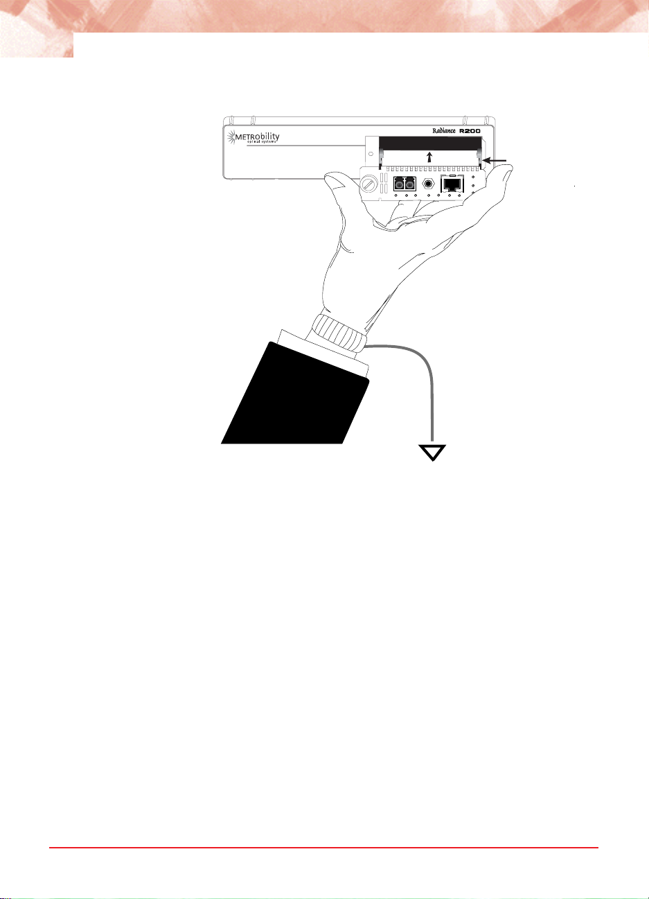
4. Install the Line Card
The Radiance services line card offers the ease of plug-and-play installation and is hot-swappable. The card must be firmly secured to the
chassis before network connections are made. Follow the simple steps
outlined below to install your line card.
• Grasp the card by the front panel as shown.
Installation Guide
Page 18
16
Card Guide
TX
RX
2
O
CON
S
E
L
LBK
DIS
LK
RX
10/100BASE
1
MAN FD PWR
SPD
RX
LK
• Insert the card into a slot in the chassis. Make sure that the top and
bottom edges of the board are aligned with the card guides in the
chassis. Do not force the card into the chassis unnecessarily. It should
slide in easily and evenly.
• Slide the card in until the top and bottom edges of the front panel are
flush and even with the edges of the chassis.
• To secure the card to the chassis, turn the thumbscrew clockwise until
it is snug. The card is now properly installed and ready for connection
to the network.venly.
5. Connect to the Network
To connect the line card to the network, remove the dust plug from the
SFP transceiver and insert the cables into the appropriate connectors as
illustrated below. Make sure the card is secured to the chassis before
making network connections.
Radiance 10/100 Mbps Services Line Card
Page 19

17
TX
RX
O
CON
S
E
L
2
SPD
LK
LBK
DIS
RX
10/100BASE
1
MAN FD PWR
RX
LK
Twisted-Pair Interface
The twisted-pair port provides a shielded RJ-45 connector that supports
a maximum segment length of 100 meters.
Fiber Optic Interface
For maximum flexibility in designing or expanding your network, the fiber
port supports any of the following Metrobility-supplied small form-factor
pluggable (SFP) transceivers. Each transceiver provides as a set of LC
or SC connectors. The maximum distance and cable type supported by
the SFP transceivers is as follows:
Model #
O280-M2 . . . . . . . . . . . . . 2 km . . . . . . . . . . . . . . .MM
. . . . . . . . . . Distance . . . . . . . . Fiber Type
O281-40. . . . . . . . . . . . . 40 km . . . . . . . . . . . . . . . SM
O281-80. . . . . . . . . . . . . 80 km . . . . . . . . . . . . . . . SM
O283-20. . . . . . . . . . . . . 20 km . . . . . . . . . . . . . . . SM
O383-20-xx . . . . . . . . . . 20 km . . . . . . . .SM (BWDM)
O483-80-xx . . . . . . . . . . 80 km . . . . . . . SM (CWDM)
Important: The distances noted are for reference purposes only. The
most important factor to achieve the desired distance is the optical power
budget. Metrobility specifications indicate the typical transmit power
budget. The actual distance is a function of the fiber type and quality, the
number and quality of splices, the type and quality of connectors, the
transmission loss, and other physical characteristics.
Installation Guide
Page 20
18
When making fiber optic connections, make sure that the transmit (TX)
optical fiber of the services line card connects to the receive (RX) optical
fiber of the connected device, and that the transmit (TX) optical fiber of
the remote device connects to the receive (RX) optical fiber of the
services line card.
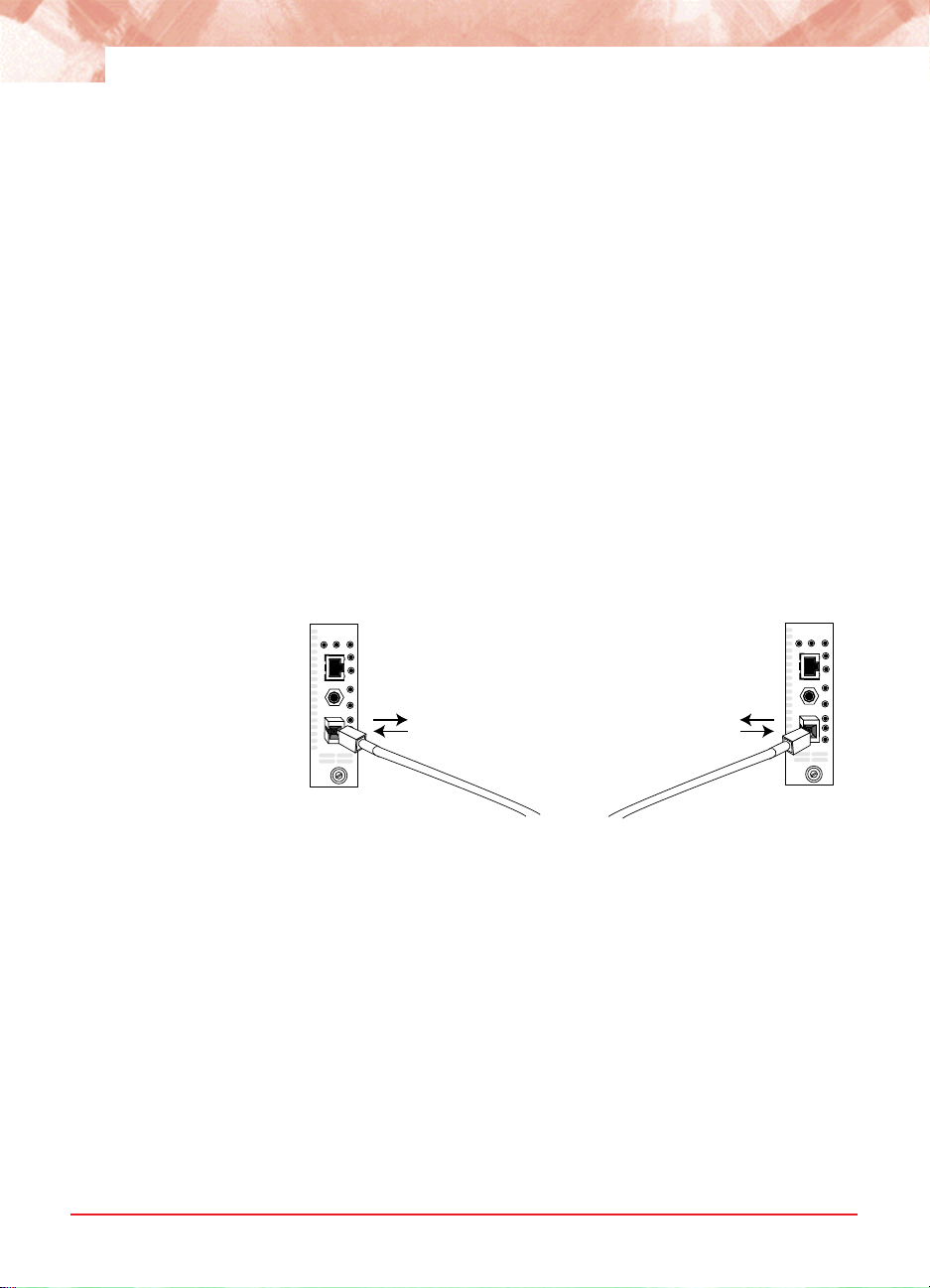
BWDM Interface
The bidirectional wavelength division multiplexed (BWDM) transceiver
provides one singlemode SC connector that supports a maximum
segment length of 20 km. BWDM transceivers must always be used in
complementary pairs. That is, the O383-20-13 must be connected to the
O383-20-55.
The O383-20-31 transmits data at a wavelength of 1310 nm and
receives at 1550 nm. Correspondingly, the O383-20-55 transmits data at
1550 nm and receives at 1310 nm.
R821 with
O383-20-31
10/100BASE
MAN FD PWR
RX
1
LK
SPD
C
O
N
S
LBK
O
L
E
DIS
RX
2
AT
TX
TX 1310 nm
RX 1550 nm
TX 1550 nm
RX 1310 nm
R821 with
O383-20-55
10/100BASE
MAN FD PWR
RX
1
LK
SPD
C
O
N
S
LBK
O
L
E
DIS
RX
2
AT
TX
TX
up to 20 km
Use the link (LK) LEDs on the front panel of the card to verify correct
segment connectivity. As you insert the cable into each port, the LK LED
will be lit if the following conditions are met:
• Power is being applied to the chassis.
• There is an active device connected to the other end of the cable, and
it is sending idle link signals.
• All connections are secure and the cables are undamaged.
• Both ends of the cable are set to the same auto-negotiation state. To
maximize device compatibility, the R821 is shipped with auto-negotiation enabled on both ports. If necessary, disable auto-negotiation and
set full duplex on the fiber port of the remote device to establish link.
Radiance 10/100 Mbps Services Line Card
Page 21
19
For information on replacing the SFP transceiver, refer to “Changing the
SFP Transceiver” on page 102 in the User Guide section.
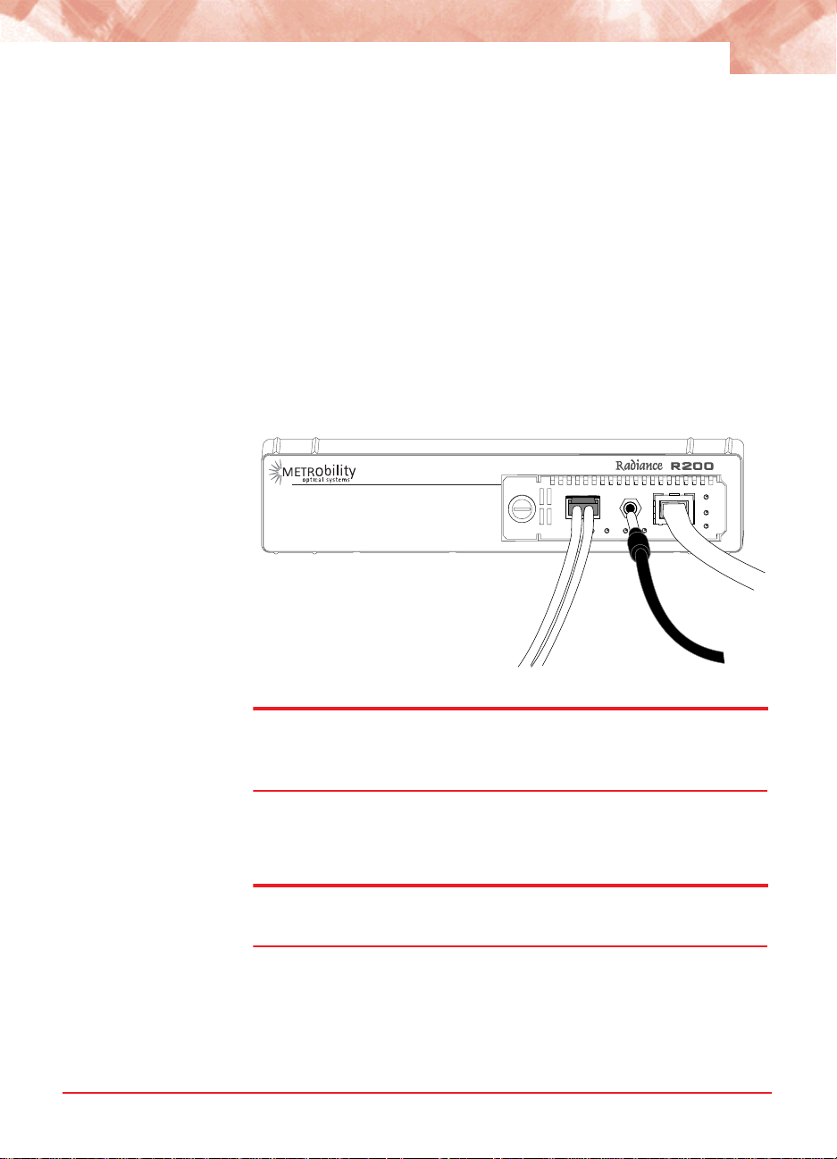
Console Port (optional)
Follow the instructions in this section if you are using a console cable
(R800-CA) to communicate directly with the R821.
Remove the dust plug from the console port. Using the R800-CA nullmodem console cable, connect the console port on the R821 to the serial
port on your PC. The cable provides a 3C plug for insertion into the
console port jack on the line card and a female DB9 connector to
connect to the PC’s DB9 port.
TX
RX
O
CON
S
E
L
2
SPD
LK
LBK
DIS
RX
LK
10/100BASE
1
MAN FD PWR
Note: Do not remove the dust plug from the console port until you are
ready to connect the console cable to the port. When you remove the
console cable, please replace the port’s dust plug.
The PC terminal session default parameters are as follows:
57,600 baud / 8 bits / 1 stop bit / no parity / no flow control
Note: All console port settings, excluding flow control, can be modified
using the set console command.
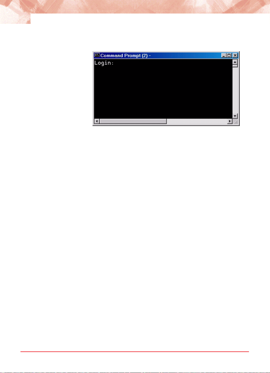
Following power-up, the boot image is automatically executed. It starts
by performing a system initialization, followed by diagnostic tests. After
diagnostics are completed successfully, a login prompt appears on the
console screen. If necessary, press <Enter> to get the login prompt.
Installation Guide
Page 22
20
If the diagnostics are unsuccessful, a failure message will appear.
When device configuration is complete, disconnect the console cable
and reinsert the dust plug.
If the console port session remains idle for 10 minutes, the connection
will automatically time out.
Radiance 10/100 Mbps Services Line Card
Page 23

Chapter 3: Management
This section contains information regarding the management and
software configuration options available on the Radiance 10/100 Mbps
services line card.
Default Software Settings
Access Port. . . . . . . . . . . . . . . . . . . . . . . . . . . . . . . . . . . . . . . . . . . Port 1
CLI Access . . . . . . . . . . . . . . . . . . . . . . . . . . . . . . . . . . . . . . . . . Enabled
DHCP Client . . . . . . . . . . . . . . . . . . . . . . . . . . . . . . . . . . . . . . . . Enabled
DHCP Server Address . . . . . . . . . . . . . . . . . . . . . . . . . . . . . . . . . 0.0.0.0
DHCP Max Retries Before Timeout . . . . . . . . . . . . . . . . . 3 (28 seconds)
DSCP Mode . . . . . . . . . . . . . . . . . . . . . . . . . . . . . . . . . . . . . . . . Disabled
DSCP Model . . . . . . . . . . . . . . . . . . . . . . . . . . . . . Expedited Forwarding
21
Far End Fault . . . . . . . . . . . . . . . . . . . . . . . . . . . . . . . . . . . . . . . Disabled
Flow Control . . . . . . . . . . . . . . . . . . . . . . . . . . . . . . . . . . . . . . . . Disabled
Forwarding Mode . . . . . . . . . . . . . . . . . . . . . . . . . . . . . . . . . Transparent
ICMP. . . . . . . . . . . . . . . . . . . . . . . . . . . . . . . . . . . . . . . . . . . . All Enabled
IP Address (zeroconf) . . . . . . . . . . . . . . . . . . . . . . . . . . . . . . .169.254.x.x
Layer 2 Control Protocols . . . . . . . . . . . . . . . . . . . . . . . . . . All Forwarded
Layer 3 Capability . . . . . . . . . . . . . . . . . . . . . . . . . . . . . . . . . . . . Enabled
Logical Services Loopback . . . . . . . . . . . . . . . . . . . . . . . . . . . . . Disabled
Loopback Mode . . . . . . . . . . . . . . . . . . . . . . . . . . . . . . . . . . . . . Disabled
Loopback Timeout . . . . . . . . . . . . . . . . . . . . . . . . . . . . . . . . .30 seconds
Management Access . . . . . . Enabled (Ports 0 and 2); Disabled (Port 1)
Management VLAN identifier . . . . . . . . . . . . . . . . . . . . . . . . 0 (Disabled)
Network Mask . . . . . . . . . . . . . . . . . . . . . . . . . . . . . . . . . . . . 255.255.0.0
OAM Admin State . . . . . . . . . . . . . . . Disabled (Port 1); Enabled (Port 2)
OAM Mode . . . . . . . . . . . . . . . . . . . . . . . Passive (Port 1); Active (Port 2)
Management
Page 24

22
P-bits Mode. . . . . . . . . . . . . . . . . . . . . . . . . . . . . . . . . . . . . . . . . Disabled
P-bits Model . . . . . . . . . . . . . . . . . . . . . . . . . . . . . . . . . . .Provider Bridge
Port Management . . . . . . . . . . . . . . . . . . . . . . . . . . . . . . . . . . . . Enabled
Port Priority Queue . . . . . . . . . . . . . . . . . . . . . . . . . . . . . . . . . . . . . . . . . 0
Port State . . . . . . . . . . . . . . . . . . . . . . . . . . . . . . . . . . . . . . . . . . Enabled
PVID (native VLAN) . . . . . . . . . . . . . . . . . . . . . . . . . . . . . . . . . . . . . . . . 1
Precedence (high-low) . . . . . . . . . . . . . . . . . . . . . . . . .p-bits, DSCP, port
RADIUS Authentication. . . . . . . . . . . . . . . . . . . . . . . . . . . . . . . . Disabled
RADIUS Retransmit . . . . . . . . . . . . . . . . . . . . . . . . . . . . . . . . . . . . . . . . 2
RADIUS Timeout . . . . . . . . . . . . . . . . . . . . . . . . . . . . . . . . . . .5 seconds
Rate Limiting. . . . . . . . . . . . . . . . . . . . . . . . . . . . . . . . . . . . . . . . Disabled
SNMP Access. . . . . . . . . . . . . . . . . . . . . . . . . . . . . . . . . . . . . . . Enabled
SNMP Administrative Community String. . . . . . . . . . . . . . . . . . . . . admin
SNMP Read-Only Community String . . . . . . . . . . . . . . . . . . . . . . . public
SNMP Read-Write Community String. . . . . . . . . . . . . . . . . . . . . . .private
Trap Destination Community String . . . . . . . . . . . . . . . . . . . . . . . . public
Trap Destination IP Address . . . . . . . . . . . . . . . . . . . . . . . . . . . . . 0.0.0.0
Trap Destination UDP Port . . . . . . . . . . . . . . . . . . . . . . . . . . . . . . . . . 162
User VLAN . . . . . . . . . . . . . . . . . . . . . . . . . . . . . . . . . . . . . . . . . Disabled
Managed Objects
MIB-II The Radiance 10/100 Mbps services line card supports the following
standard Management Information Base (MIB-II) managed object
groups, pertaining only to the end-station traffic. Objects from within
these MIB groups are accessible by and available to SNMP-based
management stations over UDP/IP.
• System (end-station only)
• Interfaces (end-station and data interface)
• IpNetToMedia (end-station only)
Radiance 10/100 Mbps Services Line Card
Page 25

• IP (end-station only)
• ICMP (end-station only)
• TCP (end-station only)
• UDP (end-station only)
• SNMP (end-station only)
• AT (end-station only)
23
EnterpriseSpecific
Objects
Admin Only SNMP Objects
Metrobility-specific managed objects provide control of the following
objects:
• End-station IP addressing information
• SNMP access communities
• Up to 4 SNMP trap destination addresses and communities
• Download server addresses
• Download management software
• Interface control (enable/disable)
• Input/output laser levels
• Management VLAN
• Management port
The Metrobility enterprise ID number is 10527.
The following SNMP objects can only be read or written by the admin
community string:
• mosDownloadServerUsername
• mosDownloadServerPassword
• mosAdminROComm
• mosAdminRWComm
• mosAdminADMINComm
• mosAdminTrapDestComm
Additionally, the following Trap Destination Table objects can be set only
when using the admin community string:
Management
Page 26

24
• mosAdminTrapDestIP
• mosAdminTrapDestPort
• mosAdminTrapDestComm
Remote Management Statistics
Through software, you can view Remote Monitoring (RMON) statistics
for the Radiance 10/100 Mbps services line card.
Each port on the card supports the complete RMON Group 1 statistics
outlined in RFC 2819 and RFC 3273.
RFC 2819
etherStatsOctets etherStatsPkts
etherStatsBroadcastPkts etherStatsMulticastPkts
etherStatsCRCAlignErrors etherStatsUndersizePkts
etherStatsFragments etherStatsJabbers
etherStatsCollisions etherStatsPkts64Octets
etherStatsPkts65to127Octets etherStatsPkts128to255Octets
etherStatsPkts256to511Octets etherStatsPkts512to1023Octets
etherStatsPkts1024to1518Octets etherStatsOversizePkts
etherStatsDropEvents
RFC 3273
etherStatsHighCapacityOverflowPkts
etherStatsHighCapacityPkts
etherStatsHighCapacityOverflowOctets
etherStatsHighCapacityOctets
etherStatsHighCapacityOverflowPkts64Octets
etherStatsHighCapacityPkts64Octets
etherStatsHighCapacityOverflowPkts65to127Octets
etherStatsHighCapacityPkts65to127Octets
etherStatsHighCapacityOverflowPkts128to255Octets
etherStatsHighCapacityPkts128to255Octets
etherStatsHighCapacityOverflowPkts256to511Octets
etherStatsHighCapacityPkts256to511Octets
etherStatsHighCapacityOverflowPkts512to1023Octets
etherStatsHighCapacityPkts512to1023Octets
etherStatsHighCapacityOverflowPkts1024to1518Octets
etherStatsHighCapacityPkts1024to1518Octets
Radiance 10/100 Mbps Services Line Card
Page 27
Setting a Secure Management Channel
By default, the R821’s VLAN identifier (VID) is 0, which indicates no
internal management VLAN. In this state, the card forwards all untagged
SNMP traffic through both ports, as illustrated below. No security is
provided, which means any device connected to any port can make
configuration changes to the R821.
R821 Services Line Card
Management Agent
Management Channel
untagged SNMP traffic untagged SNMP traffic
25
Network Port
Console Port
Access Port
Through software, you can create a secure management channel by
assigning it a new management VID
2
. The most secure configuration is
to have only one port (typically, the network port) enabled for
management. This is the recommended configuration, and it allows you
to restrict access to the card’s management agent, thus preventing
unauthorized modifications and other misuses.
The following table describes the available management options along
with the security vulnerabilities associated with each configuration.
Table 2: R821 Management Options and Vulnerabilities
Configuration Configuration Description Vulnerabilities
A management VLAN ID is assigned
Management
VLAN
(single port)
No
Management
VLAN
(single port)
Management
VLAN
(both ports)
2.Valid management VLAN IDs are in the range 1 to 4094.
to one of the ports. Only frames that
contain this VID and are from the
specified port are allowed access to
the R821 management agent.
One port is configured for
management. Any device connected
to this port can manage the R821.
A management VLAN ID is specified.
Any frame that contains the VID,
regardless of its source, is allowed to
access the R821 management agent.
None
User could respond to
ARP request and steal
R821’s IP address.
Denial of service due to
misuse of unicast MAC
address.
Management
Page 28

26
Table 2: R821 Management Options and Vulnerabilities (Continued)
Configuration Configuration Description Vulnerabilities
No
Management
VLAN
(both ports)
DEFAULT
SETTING
No security. Any device connected to
either port can manage the R821.
User could respond to
ARP and steal IP
address.
Once a management VID has been configured, set it back to 0 to disable
VLAN management.
The R821 transparently passes reserved multicast protocols such as
IEEE 802.3ad, BPDU, GMRP, and GVRP. Transporting these protocols,
however, can introduce additional possibilities for denial-of-service
attacks including traffic volume from:
• MAC addresses 01-80-C2-00-00-00 through 01-80-C2-00-00-10
— BPDU
— 802.3 slow protocols (LACP, Marker and OAM)
• GMRP and GVRP
The following table describes the misuses that could cause denial of
service when using reserved multicast protocols along with the various
management configurations.
Table 3: R821 Management Vulnerabilities When Using Reserved
Multicast Protocols
Configuration Vulnerabilities
Management
VLAN (single port)
with reserved
multicast
No Management
VLAN (single port)
Management
VLAN (both ports)
with reserved
multicast
No Management
VLAN (both ports)
with reserved
multicast
Denial of service through misuse of reserved multicast
address or 01-80-C2-00-00-02.
User could respond to ARP and steal R821’s IP address.
Denial of service through misuse of reserved multicast or
unicast MAC address.
Denial of service through misuse of reserved multicast,
unicast, or 01-80-C2-00-00-02 MAC address. User could
respond to ARP and steal the IP address.
Radiance 10/100 Mbps Services Line Card
Page 29

Software Settings
Several functions and settings on the Radiance services line card can be
modified only through software commands. This section describes the
card’s management features including IP addressing management.
27
IP Addressing Management
You can configure the R821 to obtain its IP addressing information (IP
address, network mask, and default gateway) through any of the
following means:
• DHCP assignment
• Manual configuration
• Default value
DHCP Assignment
By default, the R821 has DHCP enabled for obtaining its IP addressing
information. When DHCP is enabled, the R821 enters a discovery mode
to locate a DHCP server. The card makes up to three
resolve its IP addressing information. If any of the attempts is successful,
the card will use the information assigned by the DHCP server. The card
will also save the DHCP server’s IP address along with the address
lease time. Once the IP addressing information is acquired, the R821
preserves it in memory and renews it continuously. However, the
addressing information is not preserved across power cycles. If the card
is reset or loses power, it will enter the discovery mode again and
attempt to obtain new IP addressing information.
When DHCP is disabled, the R821 uses its last known IP addressing
information (i.e., the address that was used to issue the command to
disable DHCP). After the R821 successfully acquires its addressing information, through whatever means, Metrobility recommends disabling
DHCP to ensure that the card always uses this information. IP
addressing information is retained across power cycles when DHCP is
disabled.
3
attempts to
3.The max number of retires is configurable. The retry count starts at 4 seconds and doubles for each ad-
ditional retry (1 = 4 seconds, 2 = 12 seconds, 3 = 28 seconds, 4 = 60 seconds, 5 = 124 seconds)
Management
Page 30

28
Manual Configuration
Regardless of the DHCP setting, IP addressing information can be
assigned manually. When manually entering the IP addressing information via SNMP, you must also apply the changes by setting mosAdminApplyIPChanges to 1 in the METROBILITY-ADMIN-MIB. The R821 will
verify that the information you entered is valid and begin using the new
values if there are no problems. If for any reason there is a conflict, the
R821 will send a generic SNMP error.
Saving the IP information across power cycles depends on the DHCP
setting:
• If DHCP is disabled, the new address will be stored and preserved. If
you want to save the addressing information through resets and power
cycles, make sure DHCP is disabled after the information is entered
successfully.
• If DHCP is enabled, the R821 will enter the discovery mode at each
power cycle and attempt to obtain new IP addressing information. The
manually configured information will be maintained across a power
cycle only until a DHCP server assigns it a new IP address, or until
someone manually enters the IP addressing information again.
Default Value
To return the R821’s IP address, network mask, and gateway back their
factory default values, use the reset command and specify the default
option. Resetting the board using this method forces all software settings
back to their original values.
Start-up Failure
During the initial discovery mode, if a DHCP server is not found within
the timeout period
information using Zero Configuration Networking (zeroconf) for local
intra-subnet communication. Once the default address is generated, the
R821 enters a probing phase to verify that the address is unique. If the
address is identical to one previously claimed by another device, the
R821 will generate a new address repeatedly until it is successful. The
default zeroconf IP address is in the 169.254.0.0 network, the network
mask is 255.255.0.0, and the gateway address is 0.0.0.0.
4.The timeout period depends on the number of retries. The timeout period is configurable from 4 sec-
onds (# of retries = 1) up to 124 seconds (number of retries = 5).
Radiance 10/100 Mbps Services Line Card
4
, the R821 will generate its own default IP addressing
Page 31

29
Copper Line Quality (CLQ) Tester
Note: Do not send ARP requests (pings) to the R821 during its initialization. All ARP requests received during the probing phase
preted as address collisions and discarded. If a collision occurs, the
R821 will immediately discard the address it is verifying and generate
another one.
If DHCP is enabled, every five minutes following a successful selfgenerated address assignment, the R821 will attempt to acquire its
addressing information by locating a DHCP server.
If DHCP is disabled, the R821 will maintain its last known IP addressing
information regardless of how the information was acquired, even if it
was self-generated using zeroconf.
The R821 features a built-in cable tester that uses time domain reflectometry to identify and locate problems along the copper cable on Port 1. If
a fault occurs, you can initiate the CLQ test via software and to see what
type of problem occurred (open circuit, short circuit, or impedance
mismatch). The test also provides the distance to the fault along the
cable from the R821. The distance accuracy is +/- 2 meters.
5
are inter-
Far End Fault Far End Fault (FEF) is only applicable to the fiber port (Port 2). FEF
allows a management station to receive notification of a failure in a
remote R821’s fiber port receiver. When two services line cards are
connected through their fiber ports, FEF allows the local card to detect a
failure in the remote card’s fiber receiver. When FEF is enabled, the local
R821 will send an SNMP alarm to its trap destination(s) if a Far End
Fault condition is detected. No alarm will be sent if the condition occurs
but FEF is disabled.
Flow Control Full-Duplex Flow Control
Full-duplex flow control is provided to avoid dropping frames during
periods of network congestion. If flow control is enabled, the port will
issue a PAUSE frame whenever there is no buffer space available for
incoming frames. Full-duplex flow control applies only when the port is in
full-duplex mode with auto-negotiation enabled. Additionally, during the
negotiation process, the port’s link partner must indicate support for
PAUSE frames.
5.The probing phase lasts approximately 6 seconds.
Management
Page 32

30
The following table describes when full-duplex flow control is enabled or
disabled. In the table, “Port 1’s Link Partner” is the flow control capability
of the device connected to Port 1. The Link Partner’s capability is
obtained through auto-negotiation. 0 = disabled, 1 = enabled, and X =
not applicable.
Table 4: Full-Duplex Flow Control Modes
Port 1’s
Link Partner
XX 0Disabled
00 1Disabled
01 1Disabled
10 1Disabled
11 1Enabled
Full-Duplex Flow
Control Settings
Auto-Negotiation
Full-Duplex Flow
Control
Half-Duplex Flow Control
When a port is operating at half duplex, the R821 provides an option to
activate backpressure flow control. If half-duplex flow control is enabled,
the card will generate a jamming pattern to force a collision whenever it
cannot allocate a buffer for the port’s incoming frames.
ICMP The R821 supports Internet Control Message Protocol (ICMP) to confirm
basic network connectivity. By default, the unit is enabled to respond to
all ping requests. Through software, you can reconfigure the R821 as
follows:
• Only unicast ICMP messages are processed. The card will not process
ICMP messages sent to IP multicast, IP subnet broadcast, and IP
limited broadcast addresses.
• All ICMP messages are not processed
• All ICMP messages are processed
Note: The ICMP setting cannot be reconfigured at runtime.
Radiance 10/100 Mbps Services Line Card
Page 33

31
Loopback Modes
Loopback is provided as a means of testing connectivity and link
integrity. The R821 supports the following loopback modes:
• Local Loopback
• Remote Loopback
• OAM Loopback
• Logical Services Loopback
Once loopback is enabled, the R821 can be taken out of loopback using
one of the following means:
• Timeout. The timeout period is configurable from 30 seconds to 5
minutes. The default is 30 seconds.
• Software commands.
• A reset or full power cycle of the card.
• Removing the card and then reinserting it into the chassis.
Local Loopback
Local loopback is provided for testing link integrity on an R821
standalone NID. When local loopback is enabled on a port, the port
returns its incoming data back to the sender, while continuing to receive
and process management frames. Management frames are not looped
back to the sender—only data frames are returned. When local loopback
is enabled, the LBK LED is lit and the other Ethernet port on the card is
disabled.
Local loopback can be enabled on either Port 1 or Port 2, however, it is
typically enabled on Port 2 to evaluate the network segment by using
standard packet-generating test equipment. During local loopback, the
incoming data is transmitted through the entire circuitry of the R821
board, not just the port in loopback mode. This allows the entire circuit to
be tested. RMON statistics are incremented on both ports, even though
the physical interface of the non-loopback port is neither transmitting nor
receiving traffic.
Local
Device
Test
Equipment
Network Port
R821
NID
Remote
Device
Access Port
X
Management
Page 34

32
Remote Loopback
Remote loopback is only applicable when two R821 cards are in a backto-back configuration and they are being managed by the R502-M
management card. Remote loopback is performed on one of the ports on
the remote R821. When remote loopback is enabled on a port, the port
returns its incoming data back to the sender, while continuing to receive
and process management frames. Management frames are not looped
back to the sender—only data frames are returned. During remote
loopback, the LBK LED on the remote R821 is lit and its non-loopback
port is disabled. The LBK LED on the local R821 remains off.
Remote loopback can be enabled on either Port 1 or Port 2, however, it
is typically enabled on Port 2 to evaluate the data flow using standard
packet-generating test equipment, as shown in the illustration below.
During remote loopback, the incoming data is transmitted through the
entire circuitry of the remote R821 board, not just the port in loopback.
This allows the entire circuit to be tested. RMON statistics are incremented on both ports, even though the physical interface of the nonloopback port is neither transmitting nor receiving traffic.
Local
Device
Test
Equipment
Access Port
Local
R821
Network Port
Remote
R821
X
Access Port
Remote
Device
OAM Loopback
OAM loopback is only applicable to when two R821 services line cards
are in a back-to-back configuration with both cards connected through
their network ports. By using the 802.3ah management channel, OAM
loopback is initiated from the local R821 and performed on the remote
R821. During OAM loopback, data on the fiber line is looped at the
remote R821, returned to the local R821, and terminated there.
Because the data stream is stopped at the local R821, you do not need
any external test equipment to determine the quality of the network
segment. Instead, you can simply view the counters for the two services
line cards to see if the data is passing properly.
Radiance 10/100 Mbps Services Line Card
Page 35

33
Local
Device
Local R821
Services Line Card
Access
Remote R821
Services Line Card
Network
X
Access
X
Remote
Device
To perform OAM loopback, the following conditions must be met:
• The administrative OAM state must be enabled on both the port
which will initiate loopback and its remote peer.
• The OAM mode must be active on the port which will initiate
loopback.
• The network port on both the local and remote R821 must be in full-
duplex mode. (OAM is not supported on half-duplex links.)
• The OAM loopback status must be set to start.
If all the conditions are satisfied, the remote R821 will begin looping back
data when the local R821 initiates OAM loopback. During OAM
loopback, the remote R821 disables its non-loopback port and returns its
incoming data on the network port back to the local R821. (Management
frames are processed but not looped — only data frames are returned.)
When the data frames arrive back at the local R821, they are terminated.
During OAM loopback, the LBK LED is lit on the remote R821. The LBK
LED on the local R821 remains off.
Logical Services Loopback
Logical Services Loopback, a patent-pending feature of the R821,
enables you to perform loopback testing on the network port (Port 2)
without stopping the flow of normal data. Logical Services Loopback is
an in-service function that loops only specific frames. These frames are
identified by the following:
• A unique factory-assigned unicast MAC address.
• A user-defined multicast MAC address.
Through software, either one or both addresses may be selected to
identify Logical Services Loopback frames. The R821 also provides a
frame counter which records the total number of unicast and multicast
frames that have been looped.
Management
Page 36

34
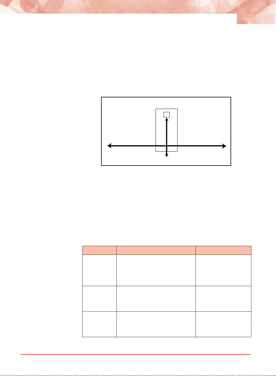
Upon receiving a Logical Services Loopback frame, the R821 services
line card performs the following operations, which are illustrated below:
• Extracts the source MAC address from the incoming frame.
• Inserts the source MAC address into the destination MAC address field
(shown in red).
• Sets the new source address to the Loopback MAC address (shown in
blue).
• Calculates the new Frame Check Sequence (FCS) and replaces the
existing FCS with the new value at the end of the frame, which is then
transmitted back to the sender.
bytes
Incoming (RX) Frame
Outgoing (TX) Frame
86
Preamble
SFD
Preamble
SFD
Dest
MAC Addr
Dest
MAC Addr
6
Source
MAC Addr
Source
MAC Addr
data
data
448+
FCS
FCS
Port Management
Loopback MAC Address
Recalculated
The data remains unchanged. Logical Services Loopback operates at full
line rate with frames of any size. Normal data frames continue to be
received and transmitted without being dropped while Logical Services
Loopback is enabled.
Local
Device
Local R821
Services Line Card
Access
Network
Remote R821
Services Line Card
Access
Remote
Device
By default, Port 2 is enabled to respond to management frames such as
ARP requests and SNMP commands. This feature is disabled on Port 1 by
default. Port management can be disabled on either port, however, it
cannot be disabled on both ports simultaneously. When management is
disabled on either port, the DIS LED turns green. A port with management
disabled discards all management frames, but data frames continue to be
received and transmitted normally.
Radiance 10/100 Mbps Services Line Card
Page 37

35
Port State You can independently enable or disable the port state on either port of
the services line card. Disabling the port state stops the flow of data to
and from that port. Although data is neither sent nor received, the
disabled port continues to accept, process, and transmit management
frames. However, if LLCF is enabled and the opposite port has no link,
management frames will not be transmitted.
Rate Limiting By default, each port allows data to flow at full line speed. The R821
supports bandwidth management that allows you to restrict the data rate
independently on each port. You can set the maximum speed on a port to
any of the following rates:
128 kbps 2 Mbps
256 kbps 4 Mbps
512 kbps 8 Mbps
1 Mbps 100 Mbps
Rate limiting consists of two parts, the rate and the state, both of which
are configurable. The rate is any of the values listed above. The state
activates or cancels rate limiting. When the rate limiting state is disabled,
the data flows without any restrictions as fast as the link allows, even if
the rate is configured to a slower setting.
When rate limiting is enabled, the data transmission rate does not
exceed the value specified. Because the R821 is a two-port device for
data transmission, setting the limit on Port 1 automatically limits the
egress (outbound) data rate on Port 2 to the same limit. Similarly, setting
the rate limit on Port 2 automatically sets the egress rate on Port 1. For
example, if you set the rate limit on Port 2 to 4 Mbps, the maximum rate
at which data can exit Port 1 will also be 4 Mbps. Port 1 and Port 2 can
be set to different rates.
4 M
8 M
Local
Device
100 M
Port 1
Local
R821
Port 2
Rate Limit
= 8 M
Port 2
Port 2
Remote
R821
Port 2
Rate Limit
= 4 M
Port 1
Remote
Device
Management
Page 38

36
Traffic Prioritization
The R821 supports Class of Service (CoS) with four priority queues (0
low, 3 high). CoS allows you to assign mission-critical data to a higher
priority, so they are processed before less critical traffic during times of
network congestion. The four CoS queues determine the priority for
transmitting data. Queues can be based on any of the following classifications:
• priority bits (p-bits) in the VLAN header
• DSCP/TOS (differentiated services code point / type of service) bits
in the header of IP frames
• default port priority bits
Precedence
By default, both p-bits and DSCP classifications are disabled, and only
the port priority is used to determine the queue for each incoming frame.
The default port priority setting is not configurable; it is always enabled.
However, the other two classifications may be enabled/disabled independently. When there is more than one classification enabled, the R821
allows you to set the precedence to determine which classification will be
used first. By default, the precedence from highest to lowest is as
follows:
1. p-bits
2. DSCP bits
3. port
This means that if the frame received is priority-tagged, the p-bits will be
used to select the queue for sending the message. If the frame received
is untagged and is an IP frame, then the DSCP bits will be used to select
the queue for sending the message. If the frame is untagged and is not
an IP frame, or if both DSCP and p-bits classification are disabled, then
the default port priority will be used to select the queue. The port priority
always has the lowest precedence.
The table below describes the settings required for the various
precedence sequences supported by the R821.
Priority Order
(1 high, 3 low)
1. DSCP 2. p-bits 3. port enabled enabled DSCP
1. p-bits 2. DSCP 3. port enabled enabled p-bits (802.1p)
Radiance 10/100 Mbps Services Line Card
DSCP setting p-bits setting Precedence selection
Page 39

37
Priority Order
(1 high, 3 low)
1. DSCP 2. port enabled disabled not applicable
1. p-bits 2. port disabled enabled not applicable
port (default) disabled disabled not applicable
DSCP setting p-bits setting Precedence selection
DSCP
The R821 supports Differentiated Services Code Point (DSCP) classification and provides four pre-defined models which map each DSCP
value to a queue.
The general format for the Differentiated Services field is shown below:
DS5 DS4 DS3 DS2 DS1 DS0 ECN=0 ECN=0
The first six bits (DS5 through DS0) are the DSCP bits. The last two bits,
the Early Congestion Notification (ECN) bits, are set to 0 and not used by
the R821.
The R821 provides the following pre-defined DSCP models:
• TOS (Type of Service)
• SP (Straight Precedence)
• EF (Expedited Forwarding) This is the default option.
• AF (Assured Forwarding)
The R821 also supports a free form configuration, which allows you to
define your own DSCP-to-queue mappings. Refer to “Free Form
Settings” on page 41.
The DSCP bit value to queue mappings are provided below:
Type of Service
000000: 0 000001: 0 000010: 0 000011: 0
000100: 0 000101: 0 000110: 0 000111: 0
001000: 0 001001: 0 001010: 0 001011: 0
001100: 0 001101: 0 001110: 0 001111 : 0
010000: 1 010001: 1 010010: 1 010011: 1
010100: 1 010101: 1 010110: 1 010111: 1
011000: 1 011001: 1 011010: 1 011011: 1
011100: 1 011101: 1 011110: 1 011111: 1
Management
Page 40

38
100000: 2 100001: 2 100010: 2 100011: 2
100100: 2 100101: 2 100110: 2 100111: 2
101000: 2 101001: 2 101010: 2 101011: 2
101100: 2 101101: 2 101110: 2 101111 : 2
110000: 3 110001: 3 110010: 3 110011: 3
110100: 3 110101: 3 110110: 3 110111: 3
111000: 3 111001: 3 111010: 3 111011: 3
111100: 3 111101: 3 111110: 3 111111: 3
Straight Precedence
000000: 0 000001: 0 000010: 0 000011: 0
000100: 0 000101: 0 000110: 0 000111: 0
001000: 0 001001: 0 001010: 0 001011: 0
001100: 0 001101: 0 001110: 0 001111 : 0
010000: 1 010001: 0 010010: 1 010011: 0
010100: 1 010101: 0 010110: 1 010111: 0
011000: 1 011001: 0 011010: 1 011011: 0
011100: 1 011101: 0 011110: 1 011111: 0
100000: 2 100001: 0 100010: 2 100011: 0
100100: 2 100101: 0 100110: 2 100111: 0
101000: 2 101001: 0 101010: 0 101011: 0
101100: 0 101101: 0 101110: 2 101111 : 0
110000: 3 110001: 0 110010: 0 110011: 0
110100: 0 110101: 0 110110: 0 110111: 0
111000: 3 111001: 0 111010: 0 111011: 0
111100: 0 111101: 0 111110: 0 111111: 0
Radiance 10/100 Mbps Services Line Card
Page 41

Expedited Forwarding
000000: 0 000001: 0 000010: 0 000011: 0
000100: 0 000101: 0 000110: 0 000111: 0
001000: 0 001001: 0 001010: 1 001011: 0
001100: 1 001101: 0 001110: 1 001111 : 0
010000: 1 010001: 0 010010: 1 010011: 0
010100: 1 010101: 0 010110: 1 010111: 0
011000: 1 011001: 0 011010: 2 011011: 0
011100: 2 011101: 0 011110: 2 011111: 0
100000: 2 100001: 0 100010: 2 100011: 0
100100: 2 100101: 0 100110: 2 100111: 0
101000: 2 101001: 0 101010: 0 101011: 0
101100: 0 101101: 0 101110: 3 101111 : 0
110000: 3 110001: 0 110010: 0 110011: 0
110100: 0 110101: 0 110110: 0 110111: 0
111000: 3 111001: 0 111010: 0 111011: 0
111100: 0 111101: 0 111110: 0 111111: 0
Assured Forwarding
39
000000: 0 000001: 0 000010: 0 000011: 0
000100: 0 000101: 0 000110: 0 000111: 0
001000: 0 001001: 0 001010: 0 001011: 0
001100: 0 001101: 0 001110: 0 001111 : 0
010000: 1 010001: 0 010010: 1 010011: 0
010100: 1 010101: 0 010110: 1 010111: 0
011000: 1 011001: 0 011010: 2 011011: 0
011100: 2 011101: 0 011110: 2 011111: 0
100000: 2 100001: 0 100010: 3 100011: 0
100100: 3 100101: 0 100110: 3 100111: 0
101000: 2 101001: 0 101010: 0 101011: 0
101100: 0 101101: 0 101110: 3 101111 : 0
110000: 3 110001: 0 110010: 0 110011: 0
110100: 0 110101: 0 110110: 0 110111: 0
111000: 3 111001: 0 111010: 0 111011: 0
111100: 0 111101: 0 111110: 0 111111: 0
Management
Page 42

40
Priority Bits
The classification of p-bits to traffic types is defined in IEEE 802.1D and
802.1ad (Provider Bridge). The R821 supports both models as well as a
free form, which allows you to define how each p-bit value will be
mapped to a queue. For more information about free form configuration,
refer to “Free Form Settings” on page 41.
When the 802.1D model is selected, the priority from highest to lowest is
Voice (< 10 ms latency and jitter), Controlled Load, Best Effort, and
Background. The 802.1D p-bits-to-queue settings are as follows:
000: 1 001: 0 010: 0 011: 1
100: 2 101: 2 110: 3 111: 3
When Provider Bridge is selected, the priority from highest to lowest is
Network Control, Voice (< 10 ms latency and jitter), Critical Applications,
and Best Effort. The Provider Bridge p-bits-to-queue settings are as
follows:
000: 0 001: 0 010: 1 011: 1
100: 2 101: 2 110: 3 111: 3
Default Port Priority
The priority bits on each port can be set independently to any value
between 0 and 7. When a port receives an untagged frame, or when both
DSCP and p-bits classifications are disabled, the frame is assigned to
the default port priority. Each priority value is mapped to a queue based
on the selected p-bits model (IEEE 802.1D or Provider Bridge). By
default, both ports are set to the lowest priority queue, 0. This means all
frames received without priority information are assigned to queue 0. It
also means all received frames are assigned to queue 0 when DSCP
and p-bits classifications are disabled.
When the IEEE 802.1D model is selected, the priority-to-queue
mappings are as follows:
0:1 1:0 2:0 3:1 4:2 5:2 6:3 7:3
When the Provider Bridge model is selected, the priority-to-queue
mappings are as follows:
0:0 1:0 2:1 3:1 4:2 5:2 6:3 7:3
Radiance 10/100 Mbps Services Line Card
Page 43

41
For example, if Port 2’s priority is set to 2 and the p-bits model is Provider
Bridge, then an untagged frame entering Port 2 will be assigned a priority
of 2. According to the Provider Bridge model, priority 2 is mapped to
queue 1, and so the frame will be processed at that priority level. Later, if
you change the p-bits model to IEEE 802.1D and keep the priority at 2,
then an untagged frame entering Port 2 will be mapped to queue 0,
because priority 2 is mapped to queue 0 under the 802.1D model.
Free Form Settings
The R821 provides four DSCP models and two p-bit models that match
pre-defined bits to a particular queue. The R821 also provides a Free
Form option that gives you the ability to individually map any DSCP or pbit value to one of the four queues.
When Free Form is specified, the R821 starts with the last configured
settings. For this reason, it is best to begin with the model that has the
closest resemblance your preferred settings. For example, if Expedited
Forwarding (EF) was the selected model before Free Form was
specified, all the DSCP bits will start with the EF mappings. From there,
you can make changes to individual bit values.
DSCP Free Form Configuration
1. Enable DSCP and set the model to Free Form (FF).
2. Specify the six binary DSCP bits you want to configure.
3. Specify the queue that will be mapped to the bits specified in the
previous step.
Example: This example shows how to map the DSCP bits 000111
and 001000 to queue 3.
Console> set dscp enable model FF
Console> set freeform dscp 000111 queue 3
Console> set freeform dscp 001000 queue 3
P-Bits (IEEE 802.1p) Free Form Configuration
1. Enable p-bits and set the model to Free Form (FF).
2. Specify the three binary p-bits you want to configure.
3. Specify the queue that will be mapped to the bits specified in the
previous step.
Example: This example shows how to set the p-bits 010 to queue 2,
and p-bits 100 to queue 4.
Management
Page 44

42
Console> set pbits enable model FF
Console> set freeform 802.1p 010 queue 2
Console> set freeform 802.1p 100 queue 4
VLAN Tagging The R821 supports three bridge forwarding modes:
• Transparent (default)
• Q-in-Q
• IEEE 802.1Q
VLAN tagging only applies to egress traffic in Q-in-Q and IEEE 802.1Q
modes. Both modes operate under an inclusive model, and one port
must be designated as the trunk port and other as the access port. By
default, the access port is Port 1 and the trunk is Port 2. VLAN tagging
and untagging rules are described in detail under “Q-in-Q Mode” on
page 44 and “IEEE 802.1Q Mode” on page 47.
The diagram below shows the VLAN tag format:
Tag Control Info
(2 bytes = 8100)
P-Bits
(3 bits)
Canonical Indicator
(1 bit = 0)
VID
(12 bits)
Q-in-Q and IEEE 802.1Q modes require a port VLAN identifier (PVID).
The default PVID is 1. The PVID is configurable and assigned as part of
a VLAN tag to untagged frames, thus allowing untagged traffic to participate in VLAN assignments. In Q-in-Q mode, the PVID is also assigned
to tagged frames as a second, or outer, tag. When the PVID is
configured, it is applied to both ports and is persistent through device
resets (i.e., the PVID is changed only when modified via software
commands).
In addition to the PVID, a VLAN tag includes three priority bits. These
bits are derived from the p-bits that were used by the R821 for internal
queuing.
Configuring the PVID alone, without enabling Q-in-Q or IEEE 802.1, will
not alter traffic. To activate VLAN tagging, you must do the following:
Q-in-Q VLAN Tagging
1. Specify transparent mode using the set switch command. If you
attempt to enable Q-in-Q while the switch is not in transparent mode,
you will receive an error message.
Radiance 10/100 Mbps Services Line Card
Page 45

43
2. Enable Q-in-Q operation using the set qinq command.
3. Specify the port VLAN identifier using the set pvid command, if you
want to use a number other than the default PVID value of 1. This
command also allows you to change the access port to Port 2.
802.1Q VLAN Tagging
1. Specify 802.1Q mode using the set switch command.
2. Specify the port VLAN identifier using the set pvid command, if you
want to use a number other than the default PVID value of 1. This
command also allows you to change the access port to Port 2.
3. Configure the user VLANs using the set uservlan command. This
command also allows untagging on the access port on a per-VLAN
basis.
Management Frames
The bridge forwarding mode does not affect the processing of IEEE
802.3ah OAM management frames. They are always delivered to, and
processed by, the R821’s CPU. DSCP and p-bit elements do not apply to
OAM frames, however, the receiver port’s queuing priority is used to
perform internal queuing. OAM frames are never tagged.
If the management channel is untagged, IP-based management frames
must also be untagged. If a management frame is received with DSCP
elements, those elements will be used for internal prioritization towards
the R821’s CPU. If management is disabled on a port, IP-based
management frames received at that port will be discarded.
If the management channel is VLAN-tagged, IP-based management
frames must be tagged with the configured management VLAN. If a
VLAN-tagged management frame is received with DSCP elements, the
elements will be used for internal prioritization towards the R821’s CPU.
If management is disabled on a port, VLAN-tagged management frames
received at that port will be discarded.
For information about how management frames are processed in Q-in-Q
mode, refer to “Management Frames in Q-in-Q Mode” on page 46.
Management
Page 46

44
Transparent Mode
Transparent mode is the default setting. In this mode, all tagged and
untagged user frames are forwarded without any modifications. All
untagged Layer 2 control protocols are also forwarded transparently,
however, these frames may be discarded on a per-protocol basis.
If a frame contains DSCP and/or p-bit elements, that information will be
used to perform internal queuing, without changing the user frame.
The example below illustrates how frames are forwarded in transparent
mode. The untagged frame (light blue) is forwarded as an untagged
frame, and the tagged frame (dark blue) with a VLAN ID of 25 is
forwarded without any changes. Traffic in both directions is handled in
the same manner.
Transparent Mode
untagged
tagged
25
Access
Port
R821
Trunk
Port
untagged
tagged
25
Q-in-Q Mode
To extend the VLAN space available under 802.1Q mode, the R821
supports the tagging of tagged frames. This results in a double-tagged
frame that becomes available for use in the service provider or Q-in-Q
domain. Double tagging preserves the original tag and applies a second
VLAN tag that is removed when the frame exits the Q-in-Q domain.
Traffic forwarding in this mode depends on whether a frame arrives at the
access port or the trunk port. The trunk port serves as the interface to the
Q-in-Q domain. VLAN tagging rules for each port are detailed below.
Traffic Forwarding Over the Trunk Port
• All frames received at the access port are forwarded with a VLAN tag
over the trunk port. Regardless of whether they are untagged, prioritytagged or VLAN-tagged, all frames received at the access port are
forwarded with the PVID assigned to them. Untagged Layer 2 control
protocols are forwarded with the PVID, however, these frames may be
discarded on a per-protocol basis. (The default PVID is 1.) All tagged
frames are forwarded with two tags—the PVID and the original tag.
The p-bits in the forwarded frames are derived from the p-bits assigned
Radiance 10/100 Mbps Services Line Card
Page 47

to the queue that was used to store the frame. This is illustrated in the
following example in which the PVID is set to 2 and the tagged frame
has a VLAN ID of 25.
Q-in-Q Mode
untagged
tagged
25
Access
Port
R821
PVID = 2
Trunk
Port
tagged
2
double-tagged
25
2
(p-bits = assigned queue)
• If a received frame contains DSCP and/or p-bit elements, and the
respective classification mode(s) is/are enabled, then that information
will be used to perform internal queuing, otherwise the access port’s
default port priority will be used for queuing.
Traffic Filtering and Forwarding Over the Access Port
• Priority-tagged frames (i.e., frames with a VLAN ID of 0) arriving at
the trunk port are discarded.
• Untagged frames, including untagged Layer 2 control protocols,
arriving at the trunk port are discarded.
45
• User frames that are single-tagged with the PVID are forwarded, but
with the tag removed.
• User frames that are double-tagged with the PVID are forwarded as
a single-tagged frame. The outer tag, which contains the PVID, is
deleted. The p-bits in the forwarded frames are derived from the pbits assigned to the queue that was used to store the frame.
• User frames which do not include the PVID are dropped.
• If the received frame contains DSCP and/or p-bit elements, that
information will be used to perform internal queuing, otherwise the
access port’s default port priority will be used for queuing.
The following example illustrates how different types of frames are
processed when they arrive at the trunk port in Q-in-Q mode.
Management
Page 48

46
Q-in-Q Mode
untagged
tagged
25
(p-bits = assigned queue)
priority-tagged
untagged
tagged without PVID
Access
Port
dropped
R821
PVID = 2
0
3
Trunk
Port
priority-tagged
0
untagged
tagged
2
double-tagged
25
2
tagged without PVID
3
Management Frames in Q-in-Q Mode
The R821 provides two options to forward management frames in Q-in-Q
mode when the management channel is tagged. One option encapsulates IP-based management frames and the other bypasses tagging. If
encapsulation is selected, a management frame will egress doubletagged with both the service provider’s tag and the management VLAN
tag. If bypass is selected, a management frame will egress single-tagged
with only the management VLAN tag.
If no management VLAN is configured, outbound management frames
always egress untagged regardless of whether encapsulate or bypass is
selected.
The following table displays how management frames are forwarded in
Q-in-Q mode under various conditions.
Encapsulate/Bypass Mgmt VLAN Mgmt Frame Tag
Encapsulate Yes Double-tagged
Encapsulate No Untagged
Bypass No Untagged
Bypass Yes Single-tagged
Radiance 10/100 Mbps Services Line Card
Page 49

47
IEEE 802.1Q Mode
In this mode, all frames leaving the trunk port are VLAN tagged to
identify the VLAN membership of a frame across bridges. The tag
identifies the frame’s VLAN and prioritization. To properly operate under
IEEE 802.1Q mode, the R821 must be configured with a list of
acceptable user VLANs. Up to 16 VLANs may be specified.
The following sections describe the filtering and forwarding process that
is applied to frames entering the access port and the trunk port.
Traffic Filtering and Forwarding Over the Trunk Port
For user data frames entering the access port, only untagged frames and
tagged frames which match one of the configured user VLANs are
forwarded. All other frames are discarded.
• Untagged frames are forwarded with the PVID assigned to them.
The p-bits in the forwarded frames are not changed.
• Tagged frames, which belong to one of the acceptable user VLANs,
are forwarded without changes to the frame.
• Priority-tagged frames (i.e., frames with a VLAN ID of 0) received at
the access port are forwarded with the the VLAN tag set to the PVID
value. The p-bits in the forwarded frames are not changed.
• Untagged Layer 2 control protocols (L2CP) are forwarded transpar-
ently, however, they may be discarded on a per-protocol basis.
• If the received frame contains DSCP and/or p-bit elements, that
information will be used to perform internal queuing, otherwise the
access port’s default port priority will be used for queuing.
The following example shows how various types of frames arriving at the
access port are processed in 802.1Q mode.
IEEE 802.1Q Mode
untagged
untagged L2CP
tagged
25
priority-tagged
0
tagged
26
Access
Port
PVID = 2
user VLAN
dropped
R821
= 10-25
26
Trunk
Port
tagged (p-bits = assigned queue)
2
untagged L2CP
tagged
25
tagged (p-bits=original)
2
Management
Page 50

48
Traffic Filtering and Forwarding Over the Access Port
The only frames that are forwarded from the trunk port to the access port
are the following:
• Untagged Layer 2 control protocols frames. Untagged L2CP are
forwarded transparently, however, they may be discarded on a perprotocol basis.
• Tagged frames containing the PVID. These frames are forwarded as
untagged frames (i.e., the PVID is removed).
• Tagged frames containing one of the configured user VLANs.
Tagged frames containing an acceptable user VLAN are forwarded
without modifications, unless untagging has been enabled. The R821
provides an option to forward frames untagged on a per-VLAN basis. For
example, if the configured user VLANs are 10-25, the access port may
be configured to untag frames for VLANs 10 and 11. Tagged frames,
whose VLANs are 10 or 11, will then be forwarded over the access port
as untagged frames. Tagged frames, whose VLANs are 12-25, will be
forwarded without any modifications, as shown in the illustration below.
The illustration also displays how different types of frames arriving at the
trunk port are processed in 802.1Q mode.
IEEE 802.1Q Mode
untagged L2CP
untagged
tagged
25
untagged
Radiance 10/100 Mbps Services Line Card
Access
Port
R821
PVID = 2
user VLAN
= 10-25
untag = 10 & 11
dropped
untagged
priority-tagged
0
tagged
26
Trunk
Port
untagged L2CP
tagged w/PVID
2
tagged
25
tagged
11
untagged
priority-tagged
0
tagged
26
Page 51

Sensors
49
Environmental Sensors
Through software, you can view environmental sensor information for
monitoring the health of the services line card. Each sensor reading
includes the current value along with the minimum and maximum values
for the component. To prevent a potential problem, a trap can be set so a
network manager is notified whenever any sensor threshold is crossed.
For more information on traps, refer to “Traps” on page 101.
Module Sensors
There are five module sensors. Module sensors measure the main circuit
board’s temperature as well as the voltage for the line card’s 1.2, 2.5, 3.3
and 5.0 volt power supplies. The 5.0 volt supply is the input power
source for the services line card. The other supplies are used to power
various components on the circuit board. The module temperature
sensor has an accuracy of ±3° C. The voltage monitoring accuracy is
±1%.
Port Sensors
The R821 includes three SFP port sensors for the fiber port. Information
is provided only when an SFP transceiver which supports diagnostics is
installed in the port. One sensor provides the internal port temperature
reading. The other two sensors provide the optical receive and transmit
power levels for the fiber port. The accuracy of the RX and TX monitors
is typically ±1 dBm.
Upgrading the Operating System Software
The R821 services line card can store two separate versions of the
operating system software. This enables you to revert to a previous
version without having to download the older version again. Downloading
and installing a new revision of the software onto the R821 is performed
via TFTP as configured through SNMP, telnet, CLI, NetBeacon, or
WebBeacon. This section describes the steps necessary to download
and activate a new version of software via SNMP. Instructions on how to
upgrade the OS using the other methods are included in the respective
user guides.
1. Copy the new binary OS image file to a TFTP server that can be
reached by the R821.
Management
Page 52

50
2. Using an SNMP MIB browser, set the following objects in METRO-
BILITY-DOWNLOAD-MIB:
• Set mosDownloadServer to the IP address of the TFTP server.
• Set mosDownloadFilename to the path and filename of the OS file
to load.
• Set mosDownloadLocation to either 3 for the primary OS file
location or 4 for the secondary OS file location. It is recommended
that you download the software into the location that is currently not
in use.
• Set mosDownloadInitiateLoad to 1 to begin loading the file. The
status of the download can be monitored via the mosDownload-
Status object.
3. When the value of mosDownloadStatus is flashBurnComplete(4),
set mosDownloadActiveOSImage to the location just loaded to.
That is, 3 if it was loaded to the primary location, or 4 if it was the
secondary location.
4. Reset the board to run the new version of the OS.
Radiance 10/100 Mbps Services Line Card
Page 53

Chapter 4: CLI Commands
This section contains a complete listing of all command line interface
(CLI) commands available on the R821. Each command includes a
detailed description of the syntax and associated parameters.
The R821 supports the following three levels of user accounts. The
default login names and passwords for each account are in parentheses.
• User (user/user)
• Administrator (admin/admin)
• Root (root/root)
The list of commands available to each user account is cumulative. That
is, the Administrator account includes all User commands, and the Root
account includes all commands.
Note: For any CLI command, you can start typing the first few letters
and then press the [Tab] key to complete the rest of the command. There
must be enough letters entered to make the command unique.
51
Notation Conventions
This chapter uses the conventions described in this section.
Font Conventions
Arial Arial is the default font used for general text.
Times This font is used for program examples, prompt responses, and
other system output.
[Key] Key names in are written in square brackets. For example, [Tab]
or [Esc].
Symbol Conventions
< > Angle brackets indicate that the enclosed information is a required
field.
CLI Commands
Page 54

52
[ ] Square brackets indicate that the enclosed information is optional,
or it is a key to press.
| A vertical bar separating two or more text items indicates that any
one of the terms may be entered as a value.
Complete List of Commands
User Commands
arp
change password
exit
help
logout
ping
show cablestatus
show console
show dhcp
show download
show fpga
show icmp
show ip
show l2controlprotocol
show l3capability
show logicalservicesloopback
show mgmtvlan
show oamcontrol
show oameventlog
show oamevents
show oamloopback
show oampeer
show oamstatistics
show os
show port
show portstatistics
show pvid
show radius
show ratelimit
show rmonportstatistics
show sensors
Radiance 10/100 Mbps Services Line Card
Page 55

show serviceclasses
show snmpuser
show snmpv1v2
show switch
show systeminfo
show trapcontrol
show trapdestinations
show uservlan
53
Administrator Commands
clear l2controlprotocol
clear mgmtvlan
clear radius server
clear uservlan
download
reset
run config
set console
set dhcp
set download
set dscp
set fpga
set freeform
set icmp
set ip
set l2controlprotocol
set l3capability
set logicalservicesloopback
set loopback
set mgmtvlan
set oamcontrol
set oamerrframe
set oamerrframeperiod
set oamerrframesecs
set oamerrsymperiod
set oamloopback
set os
set pbits
set port
set precedence
set priority
CLI Commands
Page 56

54
set pvid
set qinq
set radiusauthentication
set radiusretransmit
set radiusserver
set radiustimeout
set ratelimit
set switch
set systeminformation
set trapcontrol
set uservlan
Root Commands
clear snmpuser
clear trapdestination
clear username
set snmpcommunity
set snmpuser
set snmpv1v2
set trapdestination
set username
show snmpcommunity
show usernames
Radiance 10/100 Mbps Services Line Card
Page 57

Clear Commands
55
clear
l2controlprotocol
Description: Clear Layer 2 protocol processing action on a specified
port.
Syntax: clear l2controlprotocol <stp | rstp | mstp | lacp | marker |
802.1X | bridge | garp | gvrp | gmrp> port <port number>
Parameters: 802.1X – IEEE 802.1X Port Authentication Protocol.
bridge – LAN Bridge Management Protocol.
garp – IEEE 802 Group Attribute Registration Protocol.
gmrp – IEEE 802 GARP Multicast Registration Protocol.
gvrp – IEEE 802 GARP VLAN Registration Protocol.
lacp – IEEE 802.3ad Link Aggregation Protocol.
marker – IEEE 802.3ad Marker Protocol.
mstp – IEEE 802.1 Multiple Spanning Tree Protocol.
rstp – IEEE 802.1 Rapid Spanning Tree Protocol.
stp – IEEE 802.1 Spanning Tree Protocol.
port number – the actual port number.
Example: Console> clear l2controlprotocol garp port 2
Console>
clear mgmtvlan Description: Clear the management VLAN ID on both ports.
Syntax: clear mgmtvlan
Example: Console> clear mgmtvlan
Console>
clear radiusserver
Description: Clear a RADIUS server.
Note: This command is not available to telnet users.
Syntax: clear radiusserver <IP address>
Parameters:IP address – IP address in dotted decimal notation.
Example: Console> clear radiusserver 192.168.2.100
Console>
clear snmpuser Description: Clear name and authentication/privacy parameters for
SNMPv3 access.
Syntax: clear snmpuser <user name>
Parameters: user name – name used for SNMPv3 access.
Example: Console> clear snmpuser tempV3user
Console>
clear trapdestination
Description: Clear the destination and protocol information for a trap
destination host.
Syntax: clear trapdestination <IP address | all>
Parameters:IP address – IP address in dotted decimal notation.
all – all configured destination hosts.
CLI Commands
Page 58

56
Example: Console> clear trapdestination 192.168.1.100
Console>
clear username Description: Remove a user account from the device.
Syntax: clear username <username>
Parameters: username – username.
Example: Console> clear username guest
Console>
clear uservlan Description: Clear the specified user VLAN ID on both ports.
Syntax: clear uservlan <vlan id>
Parameters: vlan id – VLAN ID in the range 1 to 4094.
Example: Console> clear uservlan 126
Console>
System Commands
arp Description: Display the Address Resolution Protocol (ARP) table; or
add or delete an ARP entry. The R821 supports a
maximum of five ARP entries. The maximum number of
static entries is four.
Syntax: arp [all] [delete <IP address>] [static <IP address> <MAC
address>]
Parameters: all – display the ARP table.
delete – delete the ARP entry containing the specified IP
address.
static – add a static entry to the ARP table.
Display
Parameters: Intf. – Interface number.
IP address – logical IP address.
Physical address – hardware MAC address.
HW – hardware revision.
Proto – protocol type.
State – state of the address resolution process.
RESOLVED – the address has been resolved
successfully.
PENDING – address resolution is in progress, but
has not yet succeeded.
TTL – Time to live in seconds.
permanent – indicates a static entry.
Example: Console> arp all
Radiance 10/100 Mbps Services Line Card
Intf. IP address Physical address HW Proto State TTL
-----------------------------------------------------------------------------------
Page 59

57
1 192.168.1.100 00:00:d0:6a:57:b4 1 0800 RESOL VED permanent
1 192.168.1.101 00:01:d0:6d:02:00 1 0800 RESOLVED 548 s
1 192.168.1.102 00:01:5a:98:52:80 1 0800 RESOL VED 576 s
1 192.168.1.103 00:01:5a:9a:fd:58 1 0800 RESOL VED 582 s
Console>
change password
Description: Change the current user account password. The password
is a case-sensitive ASCII string (32 characters max).
Syntax: change password
Parameters: None.
Example: Console> change password
Enter current password: *****
Enter new password: *******
Re-enter new password: *******
Console>
download Description: Download the operating system, FPGA firmware, configu-
ration script, or boot code. The OS and FPGA files will be
downloaded into the inactive location. For a configuration
file, the location must be specified. If you download new
boot code, it will overwrite the existing code.
Note:The download server must first be identified using
the “set download” command before this command
can be executed. Refer to “set download” on page 60
for more information.
Syntax: download <os | fpga | config1 | config2 | boot> [set | reset |
defaults]
Parameters: os – operating system software.
fpga – FPGA embedded software.
config1 – configuration file/script instance 1.
config2 – configuration file/script instance 2.
boot – bootloader software.
set – set the newly downloaded OS or FPGA software as
active.
reset – set the newly downloaded OS or FPGA software
as active and reset the card.
defaults – set the newly downloaded OS or FPGA software
as active and reset the card to its factory default settings.
Example: Console> download config1
Console> Transferring file config1.txt
Writing image to Z80 internal FLASH
FLASH verification in progress.
Locking Z80 internal FLASH.
CLI Commands
Page 60

58
exit Description: Log off.
Syntax: exit
Parameters: None.
Example: Console> exit
help Description: Show all commands that are available to the user, along
with a brief description of the command, or all available
commands that begin with a specified word. Optionally,
press the [Tab] key to display only the commands available
to your user account. No descriptions are provided when
you use the [Tab] option.
Syntax: help [command]
[Tab]
Parameters: command – a one-word command.
Example: Console> help
arp [all] [delete <IP address>] [static <IP address> <MAC
address>]
Show, add and delete arp entries.
:
show uservlan <vlan id | all>
Show user VLAN IDs (1-4094) on both ports.
Console> help ping
ping <host> [<count> [<size> [<delay>]]]
Send ICMP echo (‘ping’) packets.
Console>
logout Description: Log off.
Syntax: logout
Parameters: None.
Example: Console> logout
ping Description: Send ICMP echo request packets to a network host.
Syntax: ping <host> [count <count>] [size <size> [delay <delay>]
Parameters: host – IP address of the network host.
count – number of packets to send. The default is 4.
Range is 1-100.
size – size of the packet in bytes. The default is 56 bytes.
Range is 56-1472.
delay – length of time (in seconds) to wait between each
request. The default is 0 seconds. The range is 0-10.
Example: Console> ping 192.168.1.100 count 2
56 octets from 192.168.1.100: icmp_seq 0
56 octets from 192.168.1.100: icmp_seq 1
received 2/2 packets (0% loss)
Console>
Radiance 10/100 Mbps Services Line Card
Page 61

59
reset Description: Reset, or reboot, the device and optionally set operational
parameters to factory defaults.
Syntax: reset [default]
Parameters: default – factory default settings.
Example: Console> reset default
run config Description: Run the saved configuration script. (Refer to “download”
on page 57 for information on downloading a script.) A
script is a text file consisting of CLI commands separated
by carriage returns. There is also an “echo” command that
can be used to print comments to the screen while the
script is running.
Syntax: run config <image number>
Parameters: image number – image number of the configuration script.
Valid numbers are 1 and 2.
Example: Configuration script:
echo Setting IP information.
set ip 192.168.1.1 mask 255.255.0.0
echo Disabling management on Port 2.
set port 2 management disable
echo Setting up VLAN information.
set mgmtvlan 101
set uservlan 167 port 1 2
set uservlan 190 port 1 2
set uservlan 233 port 1 2
Console> run config 1
Setting IP information.
Disabling management on Port 2.
Setting up VLAN information.
Console>
CLI Commands
Page 62

60
Set Commands
set console Description: Set the attributes for the console port.
Note: This command is allowed only through the console
port. It is not available to telnet users.
Syntax: set console [baud <1200-57600>] [data <7 | 8>] [stop <1 |
2>] [parity <none | even | odd>] [timeout <time in
minutes>]
Parameters: baud – speed of the console port in bits per second. The
range is 1200 to 57,600; the default is 57,600.
data – number of data bits per character. The options are 7
or 8; the default is 8 bits.
stop – number of stop bits. The options are 1 or 2; the
default is 1 bit.
parity – number of parity bits and the definition of the parity
bit if one is used. The options are:
none – no parity bits. (default)
even – one bit with even parity.
odd – one bit with odd parity.
timeout – number of minutes of inactivity on the console
port that will force it to log out automatically. The
range is 0 to 120; the default is 5 minutes. If the
timeout is set to 0, automatic log out will be disabled
(i.e., the console port will never timeout).
Example: Console> set console baud 9600 data 8 stop 1 timeout 0
Console>
set dhcp Description: Set the DHCP client’s operational mode. Optionally,
specify the number of address acquisition retries before
reverting back to the last known valid IP address.
Syntax: set dhcp <disable | enable> [# of retries]
Parameters: disable – disables DHCP client operation
enable – enables DHCP client operation.
# of retries – integer in the range 1 to 5. The default is 3.
Example: Console> set dhcp enable 5
DHCP Enabled
Retries: 5
DHCP Server: 192.168.1.100
Console>
set download Description: Set addressing information relative to the download server
used by the download command. The file will be
downloaded via TFTP.
Syntax: set download [server <IP address>] [filename <name of
file>]
Radiance 10/100 Mbps Services Line Card
Page 63

61
Parameters:IP address – IP address of the download host in dotted
decimal notation.
name of file – case-sensitive ASCII string (50 characters
max.) denoting the name of the download file.
Example: Console> set download server 192.168.1.100 filename control.bin
server: 192.168.1.100
filename: control.bin
protocol: tftp
status: Previous Flash burn completed successfully
Console>
set dscp Description: Enable or disable DSCP classification to determine traffic
prioritization and specify the policy model to use.
Syntax: set dscp <enable | disable> [model <TOS | SP | EF | AF| FF>]
Parameters: enable – enable DSCP classification.
disable – disable DSCP classification. (default)
model – set DSCP classification to one of the following
policy models:
TOS – RFC 791/795 Precedence
SP – Straight Precedence
EF – Expedited Forwarding (default)
AF – Assured Forwarding
FF – Free Form
If the model is not specified, the last configured
model will be used; the default is EF.
Example: Console> set dscp enable model AF
Console>
set fpga Description: Select the FPGA software to be used by the device.
Syntax: set fpga <image number>
Parameters: image number – 1 or 2.
Example: Console> set fpga 1
FPGA1 image (1.0.0) will not become active until next reset.
Console>
set freeform Description: Customize the free form service class policy that maps a
specific binary bit value to one of the four priority queues.
Syntax: set freeform <802.1P 0bxxx | DSCP 0bxxxxxx> queue <0-3>
Parameters: 802.1P – a three-digit binary number.
DSCP – a six-digit binary number.
queue – The priority queue value. 0 is low, 3 is high.
Example: Console> set freeform DSCP 000111 queue 3
Console>
CLI Commands
Page 64

62
set icmp Description: Set operational, processing mode for end-station ICMP
messages.
Syntax: set icmp <disable | enable | broadcastdisable>
Parameters: disable – disables processing of all ICMP messages.
enable – enables processing of all ICMP messages.
broadcastdisable – enables processing of only unicast
ICMP messages, but disables processing of ICMP
messages sent to IP multicast, IP subnet broadcast,
and IP limited broadcast addresses.
Example: Console> set icmp broadcastdisable
status: Broadcast Disabled
Console>
set ip Description: Set the device’s IP address, network mask, or default
gateway IP address.
Note: If you change the network portion of the IP address,
the default gateway must also be updated to ensure
compatibility. If the gateway cannot be reached with
the new IP address, it will not be accepted.
Syntax: set ip <IP address> [mask <mask value>] [gateway
<default gateway IP address>]
Parameters:IP address – end-station IP address in dotted decimal
notation.
mask value – the end-station prefix, or network mask in
dotted decimal notation or in /bits format.
default gateway IP address – default gateway IP address
in dotted decimal notation.
Example: Console> set ip 192.168.1.100 mask 255.255.255.0
Console>
set
l2controlprotocol
Radiance 10/100 Mbps Services Line Card
Description: Set disposition for a Layer 2 control protocol on a port.
Syntax: set l2controlprotocol <stp | rstp | mstp | lacp | marker |
Parameters: 802.1X – IEEE 802.1X Port Authentication Protocol.
802.1X| bridge | garp | gvrp | gmrp> disposition <discard |
forward | peer> port <port number>
bridge – LAN Bridge Management Protocol.
garp – IEEE 802 Group Attribute Registration Protocol.
gmrp – IEEE 802 GARP Multicast Registration Protocol.
gvrp – IEEE 802 GARP VLAN Registration Protocol.
lacp – IEEE 802.3ad Link Aggregation Protocol.
marker – IEEE 802.3ad Marker Protocol.
mstp – IEEE 802.1 Multiple Spanning Tree Protocol.
rstp – IEEE 802.1 Rapid Spanning Tree Protocol.
stp – IEEE 802.1 Spanning Tree Protocol, including Rapid
and Multiple Spanning Tree Protocols.
Page 65

63
discard – discard (filter) the specified Layer 2 control
protocol.
forward – forward the specified Layer 2 control protocol,
based on forwarding rules and policies.
peer – accept the specified Layer 2 protocol for end-station
processing.
port number – the actual port number.
Example: Console> set l2controlprotocol bridge disposition forward port 1
Console>
set l3capability Description: Set the device’s management capability to receive/transmit
IP packets.
Syntax: set l3capability <disable | enable>
Parameters: disable – disallows the reception and transmission of all IP
packets to/from the management port.
enable – allows all IP packets destined for the
management port to be received and allows the
management port to transmit IP packets.
Example: Console> set l3capability enable
IP Capability Enabled
Console>
set logicalservices loopback
Description: Configure and activate or cancel Logical Services
Loopback (LSL), which returns the specified frames back
through the port where they were received. Once LSL is
enabled, the only way to cancel it is via software.
Syntax: set logicalservicesloopback [state <disable | all | unicast |
multicast>] [address <multicast MAC address>]
Parameters: state – activate Logical Services Loopback or cancel it.
disable – cancels Logical Services Loopback.
all – enables unicast and multicast MAC frames to
be looped.
unicast – enables LSL on only unicast MAC frames.
multicast – enables LSL on only multicast MAC
frames that you specify.
address – the multicast MAC address that will be used for
Logical Services Loopback.
Example: Console> set logicalservicesloopback state unicast
Console>
set loopback Description: Activate or cancel loopback on the specified port.
Syntax: set loopback <port number> <enable | disable> [timeout
<30-300>]
Parameters: port number – the actual port number.
enable|disable – activate or cancel loopback. Enable starts
a new loopback; disable cancels the current loopback.
CLI Commands
Page 66

64
timeout – maximum number of seconds to allow the port to
remain in loopback mode. The default is 30 seconds. The
range is 30 to 300 seconds.
Example: Console> set loopback 2 enable timeout 60
Console>
set mgmtvlan Description: Set management VLAN ID. It will be applied to both ports.
The services line card supports one management VLAN
ID. The management VLAN ID number must be different
from the user VLAN ID numbers.
Syntax: set mgmtvlan <vlan id>
Parameters: vlan id – VLAN ID in the range 1 to 4094. To disable
management VLAN, set the ID to 0.
Example: Console> set mgmtvlan 1070
Console>
set oamcontrol Description: Set the OAM capabilities for the specified port.
Syntax: set oamcontrol <port number> [admin <enable | disable>]
[mode <active | passive>]
Parameters: port number – the actual port number.
admin – enable or disable administrative OAM mode for
the specified port.
mode – specify active or passive OAM mode for the
selected port. These modes differ in that active mode
provides additional capabilities to initiate monitoring
activities with the remote OAM port, while passive
mode generally waits for the remote OAM port to
initiate actions with it and responds to requests. For
example, an active OAM port can put the remote port
in a loopback state, while a passive OAM port
cannot.
Example: Console> set oamcontrol 2 admin enable mode active
Console>
set
Description: Set the OAM attributes for number of errored frames
oamerrframe
Syntax: set oamerrframe <port number> [window <# of 100ms
Parameters: port number – the actual port number.
Radiance 10/100 Mbps Services Line Card
detected for a set time window (100 ms granularity) for the
specified port, and enable or disable notification.
counts>] [threshold <frame threshold>] [notify <enable |
disable>]
window – The amount of time (in 100 ms increments) over
which the threshold is defined. The range is 10 to
600, which is equal to 1 to 60 seconds.
threshold – The number of frame errors that must occur for
the Errored Frame Event to be triggered. Example: if
Page 67

window = 100 and threshold = 5, then if 5 frame
errors occur within a window of 10 seconds, an
Event Notification OAMPDU will be generated with
an Errored Frame Event TLV indicating that the
threshold has been crossed.
notify – Enable or disable notification to the specified port’s
OAM peer that the Errored Frame Event has been
triggered.
Example: Console> set oamerrframe 2 window 100 threshold 5
Console>
65
set
oamerrframeperiod
set
oamerrframesecs
Description: Set the OAM event attributes for number of errored frames
detected for a set frame count window for the specified
port, and enable or disable notification.
Syntax: set oamerrframeperiod <port number> [window <# of
frames>] [threshold <frame threshold>] [notify <enable |
disable>]
Parameters: port number – the actual port number.
window – Number of frames over which the threshold is
defined. The range is 148,809 to 89,285,714.
threshold – The number of frame errors that must occur for
the Errored Frame Period Event to be triggered.
Example: If window = 1,000,000 and threshold = 2,
then if 2 frames out of 1,000,000 frames have errors,
an Event Notification OAMPDU will be generated
with an Errored Frame Period Event TLV indicating
that the threshold has been crossed.
notify – Enable or disable notification to the specified port’s
OAM peer that the Errored Frame Period Event has
been triggered.
Example: Console> set oamframeperiod 2 window 1000000 threshold 2
Console>
Description: Set the OAM event attributes for detection of number of
seconds with errored frames for a set time window (100
ms granularity) for the specified port, and enable or disable
notification.
Syntax: set oamerrframesecs <port number> [window <# of 100
ms counts>] [threshold <frame secs threshold>] [notify
<enable | disable>]
Parameters: port number – the actual port number.
window – The amount of time (in 100 ms intervals) over
which the threshold is defined. The range is 100 to
9000.
threshold – The number of errored frame seconds that
must occur for the Errored Frame Seconds Summary
CLI Commands
Page 68

66
Event to be triggered. The threshold range is 1 to
900. Example: if window = 100 and threshold = 5,
then if 5 frame errors occur within a window of 10
seconds, an Event Notification OAMPDU will be
generated with an Errored Frame Seconds Summary
Event TLV indicating the threshold has been
crossed.
notify – Enable or disable notification to the specified port’s
OAM peer that the Errored Frame Seconds
Summary Event has been triggered.
Example: Console> set oamerrframesecs 1 window 100 threshold 5
Console>
set
oamerrsymperiod
set oamloopback
Description: Set the OAM event attributes for number of errored
symbols detected for a set symbol count window for the
specified port, and enable or disable notification.
Note: This R821 currently does not support this command.
Syntax: set oamerrsymperiod <port number> [window <# of
symbols>] [threshold <symbol period threshold>] [notify
<enable | disable>]
Parameters: port number – the actual port number.
window – Number of symbols over which the threshold is
defined. The range is 125000000 to 3205032704.
threshold – The number of symbol errors that must occur
for the Errored Symbol Period Event to be triggered.
Example: If window = 125000000 and threshold =
20, then if 20 symbol errors occur within 125000000
symbols, an Event Notification OAMPDU will be
generated with an Errored Symbol Period Event TLV
indicating that the threshold has been crossed.
notify – Enable or disable notification to the specified port’s
OAM peer that the Errored Symbol Period Event has
been triggered.
Example: Console> set oamerrsymperiod 1 window 125000000 threshold
20
Console>
Description: Start or stop remote loopback on the specified port with
the remote OAM port.
Syntax: set oamloopback <port number> [status <start | end>]
[commands <ignore | process>]
Parameters: port number – the actual port number.
status – initiate or terminate remote loopback with the
remote port. Starting remote loopback causes the
specified port to send a loopback request (with the
loopback enable flags set) to the remote port. Ending
Radiance 10/100 Mbps Services Line Card
Page 69

remote loopback causes the specified port to send a
loopback request (with the loopback enable flags
cleared) to the remote port.
commands – process or drop incoming requests for
loopback when the specified port receives them.
Example: Console> set oamloopback 2 commands ignore
Console>
set os Description: Select the operating system image to be used by the
device. To activate the selection, you must reset the device
after changing the OS image.
Syntax: set os <image number>
Parameters: image number – 1 or 2.
Example: Console> set os 1
OS1 image (1.0.0) will not become active until next reset.
Console>
set pbits Description: Enable or disable priority bits classification, and set the
policy profile as defined in IEEE 802.1D or IEEE 802.1ad
(Provider Bridge), or use a free form definition.
Syntax: set pbits <enable | disable> [model <802.1D | Provider
Bridge | FF>]
Parameters: enable – enable p-bit classification.
disable – disable p-bit classification. (default)
model – specify the policy to use for p-bit classification.
802.1D prioritizes traffic types in the following order
(highest to lowest): Voice, Controlled Load, Best
Effort, and Background. Provider Bridge prioritizes
traffic types in the following order (highest to lowest):
Network Control, Voice, Critical Applications, and
Best Effort. FF (Free Form) allows you to define the
priority bits. If the model is not specified, the last
configured model will be used; by default it is
Provider Bridge.
Example: Console> set pbits enable model 802.1D
Console>
67
set port Description: Set attributes for a selected port.
Syntax: set port <port number> [autonegotiate <disable | enable>]
[duplex <full | half>] [flowcontrol <disable | enable>]
[management <disable | enable>] [speed <10 |100>] [state
<disable | enable>] [fef <disable | enable>] [llr <disable |
enable>] [llcf <disable | enable>]
Parameters: port number – the actual port number.
autonegotiate – disable or enable auto-negotiation for the
selected port.
CLI Commands
Page 70

68
duplex – specify full or half duplex for the selected port.
fef – disable or enable Far End Fault reporting on the
selected fiber port.
flowcontrol – disable or enable flow control for the selected
port. PAUSE frames are used on full-duplex ports,
whereas collisions are forced on half-duplex ports.
llcf – disable or enable the ability to carry forward (to the
other port) link loss on the selected port.
llr – disable or enable Link Loss Return status for the
selected port.
management – disable or enable management access
over selected port.
speed – set the speed on the selected port to 10 or 100
Mbps and disable auto-negotiation on that port. Only
Port 1’s speed is configurable.
state – disable or enable the selected port.
Example: Console> set port 1 speed 100 state enable
Console>
set precedence Description: Specify which mode (IEEE 802.1p or DSCP) will take
precedence if both modes are enabled simultaneously.
This command is ignored if only one mode is enabled or if
both modes are disabled.
Syntax: set precedence <802.1P | DSCP>
Parameters: 802.1P – 802.1p takes precedence over DSCP. (default)
DSCP – DSCP takes precedence over 802.1p.
Example: Console> set precedence DSCP
Console>
set priority Description: Set the priority bits on a port.
Syntax: set priority <port number> <0-7>
Parameters: port number – the actual port number.
0-7 – specifies the three binary bits used to identify the
priority. These bits will be mapped to a queue
depending on which p-bit model is enabled, either
Provider Bridge or IEEE 802.1D).
0 = 000 4 = 100
1 = 001 5 = 101
2 = 010 6 = 110
3 = 011 7 = 111
Example: Console> set priority 2 4
Console>
Radiance 10/100 Mbps Services Line Card
Page 71

69
set pvid Description: Set the port VLAN identifier that will be used for tagging
when 802.1Q and Q-in-Q modes are enabled. When the
switch mode is set to Transparent, the PVID is used as the
native VLAN for untagged frames.
Syntax: set pvid <VLAN> [access <port number>]
Parameters: VLAN – VLAN ID in the range 1 to 4094.
access – specifies the access port. If not specified, the
access port will be the port that was last configured
to be the access port. By default, it is Port 1.
Example: Console> set pvid 3
Console>
set qinq Description: Enable or disable Q-in-Q operation, and optionally bypass
or encapsulate management frames when a management
VLAN is configured.
Syntax: set qinq <enable | disable> [management <bypass| encap-
sulate>]
Parameters: enable – activates Q-in-Q forwarding mode. For more
information, refer to “Q-in-Q Mode” on page 44. Q-inQ operation can only be enabled when the switch is
in transparent mode. If the switch is in 802.1Q mode,
an error message will appear.
disable – Q-in-Q mode is disabled. The forwarding mode
will be determined by the ‘set switch’ setting.
management – encapsulate or bypass management
frames when Q-in-Q is enabled. For more information, refer to “Management Frames in Q-in-Q
Mode” on page 46.
bypass – if no management VLAN is configured,
allows all management frames to bypass the service
provider tag on the trunk port. That is, management
frames will egress the trunk port untagged. If the
management VLAN is configured, management
frames will egress single-tagged with only the
management VLAN. This is the default setting.
encapsulate – encapsulates all management frames
when there is a management VLAN configured. This
results in double-tagged management frames. If no
management VLAN is configured, management
frames will egress untagged.
Example: Console> set qinq enable
Console>
CLI Commands
Page 72

70
set
radiusauthentication
set radiusretransmit
set radiusserver
Description: Enable or disable RADIUS authentication.
Note: This command is not available to telnet users.
Syntax: set radiusauthentication <all | telnet | console> <enable |
disable>
Parameters: all – authenticates all attempts to access the system.
telnet – authenticates access via telnet only.
console – authenticates access only when it is directly
from the connected console port.
enable – enable RADIUS authentication.
disable – disable RADIUS authentication.
Example: Console> set radiusauthentication all enable
Console>
Description: Set number of transmission retries to a RADIUS server.
Syntax: set radiusretransmit <count>
Parameters: count – specifies the maximum number of attempts to
send a request to a RADIUS server without receiving
a response. The range is 1-10; the default is 2.
Example: Console> set radiusretransmit 3
Console>
Description: Set configuration paramaters for a RADIUS server.
Note: This command is not available to telnet users.
Syntax: set radiusserver <IP address> secret <secret> [port <UDP
port>] [primary]
Parameters:IP address – RADIUS server’s IP address in dotted
decimal notation.
secret – the password (max 65 characters) that has been
assigned to the RADIUS server.
port – the UDP port number. The default is 1812.
primary – indicates that the specified RADIUS server will
be the primary RADIUS server.
Example: Console> set radiusserver 192.168.2.100 secret mypassword
Console>
set radiustimeout
Radiance 10/100 Mbps Services Line Card
Description: Set the time interval (in seconds) between attempts to
Syntax: set radiustimeout <time in seconds>
Parameters: time in seconds – time interval (in seconds) to wait for a
Example: Console> set radiustimeout 6
authenticate with a RADIUS server.
reply from a RADIUS server. The range is 1-10; the
default is 5 seconds.
Console>
Page 73

set ratelimit Description: Set the rate limit on the specified port or activate/cancel
rate limiting.
Syntax: set ratelimit <port number> [rate <128 | 256 | 512 | 1000 |
2000 | 4000 | 8000 | 100000>] [state <disable | enable>]
Parameters: port number – the actual port number.
rate – specify the ingress (inbound) traffic rate limit in Kbps
on the selected port to one of the following rates:
128, 256, 1000, 2000, 4000, 8000, or 100000.
Because the R821 is a two-port device, changing the
ingress rate automatically changes the egress
(outbound) rate on the opposite port.
state – activate or cancel rate limiting.
disable – cancel rate limiting and allow traffic to flow
at full line rate.
enable – activate rate limiting. The maximum rate is
set to the value specified by the rate option.
Example: Console> set ratelimit 1 rate 8000 state enable
Console>
71
set snmpcommunity
Description: Set SNMP community and its corresponding access profile.
Syntax: set snmpcommunity <community name> profile <ro |rw |
admin>
Parameters: community name – a case-sensitive ASCII string (up to 50
characters in length) denoting the receive profile on
the trap destination host. If unspecified, the default
value is NULL.
profile – specifies the access profile for a community user.
ro – read-only access to non-privileged objects.
rw – read-write access to non-privileged objects.
admin – full read-write access to all objects.
Example: Console> set snmpcommunity public profile ro
Console>
set snmpuser Description: Set the name along with the authentication and privacy param-
eters for SNMPv3 access.
Syntax: set snmpuser <user name> auth <none | md5> [authpwd
<auth password>] priv <none | des> [privpwd <priv
password>] group <ro | rw | admin>
Parameters: user name – a case-sensitive ASCII string (up to 50
characters in length) denoting the user name that
has SNMPv3 access to the device.
auth – identifies the authentication protocol.
none – No authentication is performed.
md5 – MD5 protocol is used to encrypt the authenti-
cation process. This option requires an authenti-
cation password.
CLI Commands
Page 74

72
auth password – a case-sensitive ASCII string (up to 50
characters in length) denoting the password
associated with the user when MD5 authentication is
specified.
priv – identifies the privacy protocol.
none – No privacy. Messages are not encryted.
des – Messages sent by the user are encrypted
using the DES protocol. This option requires a
privacy password.
priv password – a case-sensitive ASCII string (up to 50
characters in length) denoting the password
associated with the user when the DES protocol is
specified for encrypting messages.
group – specifies the access profile for the SNMPv3 user.
ro – read-only access to non-privileged objects.
rw – read-write access to non-privileged objects.
admin – full read-write access to all objects.
Example: Console> set snmpuser v3guest auth none priv none group ro
Console>
set snmpv1v2 Description: Enable or disable SNMPv1 and SNMPv2c access.
Syntax: set snmpv1v2 <enable | disable>
Parameters: enable – enable SNMPv1 and SNMPv2c access.
disable – disable SNMPv1 and SNMPv2c access.
Example: Console> set snmpv1v2 enable
Console>
set switch Description: Specify the forwarding mode.
Syntax: set switch <Transparent | 802.1Q>
Parameters:Transparent – specifies transparent forwarding. The R821
is transparent to user data traffic.Tagged and
untagged frames are forwarded unchanged.
802.1Q – specifies that the R821 complies with IEEE
802.1Q VLAN bridge forwarding aspects. For more
information, refer to “IEEE 802.1Q Mode” on
page 47.
Example: Console> set switch transparent
Console>
set systeminformation
Radiance 10/100 Mbps Services Line Card
Description: Set system information.
Syntax: set systeminformation <administrative> [name <system
name>] [location <location name>] [contact <contact>]
Parameters: administrative – the administrative SNMP community
string. The default is admin.
system name – a case-sensitive ASCII string (up to 50
characters in length) denoting the assigned adminis-
Page 75

73
trative name. Multi-word strings must be placed in
quotation marks. If unspecified, the default value is
NULL.
location name – a case-sensitive ASCII string (up to 50
characters in length) denoting the assigned adminis-
trative location. Multi-word strings must be placed in
quotation marks. If unspecified, the default value is
NULL.
contact – a case-sensitive ASCII string (up to 50
characters in length) denoting the contact name.
Multi-word strings must be placed in quotation
marks. If unspecified, the default value is NULL.
Example: Console> set systeminformation admin name “A B” location 45
Console>
set trapcontrol Description: Set trap handling for a specified trap on a per destination
basis.
Syntax: set trapcontrol <trap index> host <IP address> state
<disable | enable>
Parameters: trap index – trap number as defined in MIB-II.
IP address – trap destination host’s IP address in dotted
decimal notation.
state – enable or disable the specified trap.
Example: Console> set trapcontrol 4 host 192.168.1.100 state enable
Console>
set trapdestination
Description: Set the destination and protocol information for a trap
destination host. Up to four trap destinations may be
configured.
Syntax: set trapdestination <IP address> [port <UDP port>]
[version <SNMP version>] [community <trap community>]
[username <SNMP security name>]
Parameters:IP address – trap destination’s IP address in dotted
decimal notation.
UDP port – UDP transport port number in the range 1 to
65535. The default value is 162 for SNMP, and 9162
for management via NetBeacon.
SNMP version – SNMP version number: 1, 2, or 3. The
default value is 1.
trap community – a case-sensitive ASCII string (up to 32
characters in length) denoting the receive profile on
the trap destination host. The default value is public.
SNMP security name – a case-sensitive ASCII string (up to
32 characters in length) denoting the user name for
SNMPv3 traps. The username is a required field for
CLI Commands
Page 76

74
SNMPv3 traps.
Example: Console> set trapdestination 192.168.1.100 port 9162 version 3
username v3user
Console>
set username Description: Set the username, password, and access for user login.
Syntax: set username <user name> password <user password>
access <user | admin | root>
Parameters: user name – a case-sensitive ASCII string up to 32
characters in length.
user password – a case-sensitive ASCII string up to 32
characters in length.
access – specifies the access level for a user login.
user – read-only access to non-privileged objects.
admin – read-write access to non-privileged objects.
root – full read-write access to all objects.
Example: Console> set username guest password guest access user
Console>
set uservlan Description: Set the user VLAN ID on one or more ports. (The R821
requires both ports to be set to the same user VLAN(s).)
The user VLAN ID must be different from any previously
provisioned management VLAN ID(s). Up to 16 user VLAN
IDs are supported.
Syntax: set uservlan <vlan id> port <port number[untag] ... [port
number n]>
Parameters: vlan id – VLAN ID in the range 1 to 4094.
port number – the port number to which the user VLAN is
assigned.
untag – remove the specified uservlan tag from frames
that egress the access port. Untagging is not allowed
on the trunk port. Untagging is only applicable in
IEEE 802.1Q mode.
Example: Console> set uservlan 22 port 1untag 2
Console> set uservlan 23 port 1 2
Console>
Radiance 10/100 Mbps Services Line Card
Page 77

Show Commands
75
show cablestatus
Description: Show results of the copper line quality test for copper port.
Syntax: show cablestatus <port number>
Parameters: port number – the actual port number.
Display
Parameters: Good – no problems are detected on the copper cable.
Open – There is an open circuit along the copper cable.
Short – There is a short circuit along the copper cable.
Impedance Mismatch – There is an impedance mismatch
along the copper cable.
Example: Console> show cablestatus 1
Copper Pair 1....: Good
Copper Pair 2....: Cable Open @ 30 Meters
Console>
show console Description: Show the attributes for the console port.
Syntax: show console
Display
Parameters: Baud – speed of the console port in bits per second.
Data bits – Number of data bits per character.
Stop bits – Number of stop bits.
Parity – Number and type of parity. None is no parity bits;
even is one bit with even parity. Odd is one bit with
odd parity.
Timeout – Number of minutes of inactivity after which the
console port will automatically log out.
Example: Console> show console
Baud Data bits Stop bits Parity Timeout
9600 8 1 none 5
Console>
show dhcp Description: Show the DHCP client’s operational mode and operation
parameters.
Syntax: show dhcp
Display
Parameters: DHCP – identifies the operational mode.
disabled – DHCP client operation is disabled.
enabled – DHCP client operation is enabled.
Retries – specifies the number of address acquisition
retries before reverting to using the last known valid
IP address.
dhcp server – IP address of the current DHCP server.
Example: Console> show dhcp
CLI Commands
Page 78

76
DHCP Enabled
Retries: 3
DHCP Server: 192.168.1.100
Console>
show download Description: Show addressing information relative to the download
server used by the download command, along with the
status of the current download.
Syntax: show download
Display
Parameters: server – identifies IP address of the download host.
filename – identifies the name of the download file.
protocol – identifies the download protocol. The R821 only
supports TFTP (Trivial File Transfer Protocol).
status – identifies the status of the current download. The
status can be any of the following descriptions:
Transfer in progress
Transfer complete
Flash burn in progress
Flash burn complete
Transfer failed
Flash burn failed
Note: The “status” parameter will only displayed if software
has been downloaded since the device was last
reset or booted.
Example: Console> show download
server: 192.168.1.100
filename: control.bin
protocol: tftp
status: Previous Flash burn completed successfully
Console>
show fpga Description: Show the image number and revision of the active FPGA
software.
Syntax: show fpga
Example: Console> show fpga
Active FPGA image number: 1
Rev: 1.01.02
Console>
show icmp Description: Show operational, processing mode for end-station ICMP
messages.
Syntax: show icmp
Display
Parameters: status – identifies the processing state of the end-station
ICMP messages.
Radiance 10/100 Mbps Services Line Card
Page 79

All Disabled – ICMP message processing is disabled.
All Enabled – ICMP message processing is enabled.
Broadcast Disabled – the processing of only unicast
ICMP messages is enabled. The processing of ICMP
messages sent to IP multicast, IP subnet broadcast,
and IP limited broadcast addresses is disabled.
Example: Console> show icmp
status: All Enabled
Console>
show ip Description: Show the device’s IP address, corresponding network
mask, and the default gateway IP address.
Syntax: show ip
Display
Parameters:IP Address – identifies the end-station IP address.
IP Mask – identifies the end-station prefix (network mask).
Default Gateway – identifies the default route gateway IP
address.
Example: Console> show ip
IP Address: 192.168.1.100
IP Mask: 255.255.255.0
Default Gateway: 192.168.1.254
Console>
77
show
l2controlprotocol
Description: Show the disposition for Layer 2 protocols on one or more
ports.
Syntax: show l2controlprotocol <stp | rstp | mstp | lacp | marker | 802.1X |
bridge | garp | gvrp | gmrp | all> port <port number | all>
Parameters: 802.1X – IEEE 802.1X Port Authentication Protocol.
bridge – LAN Bridge Management Protocol.
garp – IEEE 802 Group Attribute Registration Protocol.
gmrp – IEEE 802 GARP Multicast Registration Protocol.
gvrp – IEEE 802 GARP VLAN Registration Protocol.
lacp – IEEE 802.3ad Link Aggregation Protocol.
marker – IEEE 802.3ad Marker Protocol.
mstp – IEEE 802.1 Multiple Spanning Tree Protocol.
rstp – IEEE 802.1 Rapid Spanning Tree Protocol.
stp – IEEE 802.1 Spanning Tree Protocol, including Rapid
and Multiple Spanning Tree Protocols.
port number – the actual port number.
all – all three ports.
Display
Parameters: Discard – specified protocol is being discarded (filtered).
Forward – specified protocol is being forwarded, based on
forwarding rules and policies.
CLI Commands
Page 80

78
Peer – specified protocol is being accepted for end-station
processing.
Example: Console> show l2controlprotocol bridge port 2
Port 0:
bridge: Forward
Port 1:
bridge: Forward
Port 2:
bridge: Forward
Console>
show l3capability
show logicalservices loopback
Description: Show the device’s management capability to receive/
transmit IP packets.
Syntax: show l3capability
Example: Console> show l3capability
L3 Capability Enabled
Console>
Description: Show the configuration and statistics for Logical Services
Loopback (LSL).
Syntax: show logicalservicesloopback
Display
Parameters: State – specifies the LSL state (enabled or disabled). If
enabled, the state will specify the type of frames that
have been configured for looping. (i.e., unicast
frames, multicast frames, or all frames).
Unicast MAC Address – specifies the unicast MAC
address hat is used for LSL.
Multicast MAC Address – specifies the multicast MAC
address that is used for LSL.
Total frames looped – specifies the total number of unicast
and multicast frames that have been looped.
Example: Console> show logicalservicesloopback
State . . . . . . . . . . . . . . . . . . . : disabled
Unicast MAC Address . . . . . : 00:40:9f:18:1f:6e
Multicast MAC Address . . . . : 00:00:00:00:00:00
Total frames looped . . . . . . . : 0
Console>
show mgmtvlan Description: Show the management VLAN ID (1-4094) for both ports, if
it has been assigned.
Syntax: show mgmtvlan
Example: Console> show mgmtvlan
Management Disabled
Console>
Radiance 10/100 Mbps Services Line Card
Page 81

79
show oamcontrol
Description: Show the primary controls and status for the 802.3ah OAM
capabilities for the specified port or all ports.
Syntax: show oamcontrol <port number | all>
Parameters: port number – the actual port number.
all – specifies all ports.
Display
Parameters: Admin State – indicates the desired administrative OAM
state for the specified port.
DISABLED – OAM is in disabled.
ENABLED – OAM is in enabled.
Note: The Admin State is ignored when the port is not in
full-duplex mode. OAM is not supported on half-
duplex links.
Operational Status – identifies the OAM capability deter-
mined during initialization between the specified port
and its peer, which is the remote port on the opposite
end of the link.
DISABLED – OAM is disabled administratively on
the specified port.
LINK FAULT – The port has detected a fault and is
transmitting OAMPDUs with a link fault indication.
PASSIVE WAIT – The port is in passive OAM mode
and is waiting to see if the remote port is capable of
OAM.
ACTIVE SEND LOCAL – The port is in active OAM
mode and is trying to discover whether the remote
port has OAM capability but has not yet made that
determination.
SEND LOCAL AND REMOTE – The port has
discovered its peer, but has not yet accepted or
rejected the peer’s configuration.
SEND LOCAL AND REMOTE OK – The port has
accepted OAM peering with the remote port.
OAM PEERING LOCALLY REJECTED – The port
has rejected OAM peering with the remote port.
OAM PEERING REMOTELY REJECTED – The
remote port has rejected OAM peering.
OPERATIONAL – Both the port and the remote port
have accepted peering.
Mode – identifies the mode of OAM operation for the port.
PASSIVE – Port waits for the remote port to initiate
OAM actions with it, but cannot initiate actions itself.
ACTIVE – The port can initiate monitoring activities
with the remote port.
Max PDU Size – indicates largest OAMPDU that the port
supports. The port exchanges maximum OAMPDU
sizes with its peer, and both ports negotiate to use
CLI Commands
Page 82

80
the smaller of the two maximum sizes between them.
Config Revision – indicates the configuration revision of
the port as reflected in the latest OAMPDU sent by
the port. The configuration revision is used to
indicate configuration changes that have occurred
which might require the remote port to re-evaluate
whether peering is allowed.
Supported Functions– identifies OAM functions supported
by the port. One or more of the following functions
may be supported: UNIDIRECTIONAL,
LOOPBACK, EVENT, VARIABLE.
Vendor Specific Info– indicates whether or not the services
line card is under the control of a management card.
Proxy Managed – The services line card is installed
in a chassis with a management card and is under its
control.
None – The services line card is not being managed
by a management card (e.g., it is a standalone NID).
Example: Console> show oamcontrol 2
Port 2 Information:
Admin State . . . . . . . . . : ENABLED (2)
Operational Status . . . . : ACTIVE SEND LOCAL (4)
Mode. . . . . . . . . . . . . . . : ACTIVE (1)
Max PDU Size . . . . . . . : 1518
Config Revision . . . . . . : 2
Supported Functions. . . : LOOPBACK
EVENT
Vendor Specific Info . . . : Proxy Managed
Console>
show
Description: Show a history of events that have occurred at the
oameventlog
Syntax: show oameventlog <port number | all>
Parameters: port number – the actual port number.
Display
Parameters:Timestamp – The R821’s system uptime value when the
Radiance 10/100 Mbps Services Line Card
Ethernet OAM level. These events can be detected locally
or remotely. Ethernet OAM events can be signaled by
Event Notification OAMPDUs or by the flags field in any
OAMPDU. The R821 stores up to 40 event log entries.
all – specifies all ports.
event occurred.
OUI – The Organizational Unique Identifier. Excluding event
TLVs that are unique to an organization, all IEEE
802.3 events use the OUI of 0180C2. Organizations
that define their own event notification TLVs include
their OUI in the TLVs which gets reflected here.
Type – The type of event that generated this entry in the
Page 83

event log. When the OUI is 0180C2, the following
event types are defined:
Errored Symbol Event
Errored Frame Period Event
Errored Frame Event
Errored Frame Seconds Event
Link Fault Event
Dying Gasp Event
Critical Link Event
The first four types are threshold crossing events
which are generated when a metric exceeds a given
value within a specified window. The other three
types are not threshold crossing events.
Location – Indicates whether the event occurred locally, or
was received from the OAM peer via Ethernet OAM.
Window – For a threshold crossing event, the period over
which the value was measured for the event (e.g.: 5,
when 11 occurrences happened in 5 seconds while
the threshold was 10).
Threshold– For a threshold crossing event, the limit that
was crossed for the event to be logged (e.g.: 10,
when 11 occurrences happened in 5 seconds while
the threshold was 10).
Value – For a threshold crossing event, this indicates the
number of occurrences within the given window that
generated this event (e.g.: 11, when 11 occurrences
happened in 5 seconds while the threshold was 10).
Running Total – The total number of times this occurrence
has happened since the last reset (e.g.: 987, when
987 symbol errors resulted in 18 symbol error
threshold crossing events since the last reset).
Event Total – The total number of times one or more of
these occurrences resulted in an event since the last
reset (e.g.: 18, when 987 symbol errors resulted in
18 symbol error threshold crossing events since the
last reset).
Example: Console> show oameventlog all
81
Port 1:
Port 2:
Timestamp: 0 days 0h:0 m:19.93s
OUI: 01 80 c2 Type: Link Fault Event Location: Local
Window: none Threshold: none Value: none
Running Total: 1 Event Total: 1
Console>
CLI Commands
Page 84

82
show oamevents
Description: Show the windows, thresholds, and notification states for
generating standard Ethernet OAM events for the
specified port(s).
Syntax: show oamevents <port number | all>
Parameters: port number – the actual port number.
all – specifies all ports.
Display
Parameters: Error Symbol Period Window – The number of symbols (N)
over which the threshold is defined.
Error Symbol Period Threshold – The number of symbol
errors (n) that must occur for the Errored Symbol
Period Event to be triggered. If n out of N symbols
had errors, an Errored Symbol Period Event notification OAMPDU will be generated.
Error Symbol Period Notify – Indicates whether generating
an event notification is enabled or disabled for
Errored Symbol Period events.
Error Frame Period Window – The number of frames (N)
over which the threshold is defined.
Error Frame Period Threshold – The number of frame
errors (n) that must occur for the Errored Frame
Period Event to be triggered. If n out of N frames had
errors, an Errored Frame Period Event notification
OAMPDU will be generated.
Error Frame Period Notify – Indicates whether generating
an event notification is enabled or disabled for
Errored Frame Period events.
Error Frame Window – The amount of time (T), in 100 ms
increments, over which the threshold is defined.
Error Frame Threshold – The number of frame errors (n)
that must occur for the Errored Frame Event to be
triggered. If n frames in T (in tenths of a second) had
errors, an Errored Frame Event notification
OAMPDU will be generated.
Error Frame Notify – Indicates whether generating an
event notification is enabled or disabled for Errored
Frame events.
Error Frame Seconds Summary Window – The amount of
time (T), in 100 ms increments, over which the
threshold is defined.
Error Frame Seconds Summary Threshold – The number
of errored frame seconds (n) that must occur for the
Errored Frame Seconds Summary Event to be
triggered. If n frame errors occur in T (in tenths of a
second), an Errored Frame Seconds Summary
Event notification OAMPDU will be generated.
Error Frame Seconds Summary Notify – Indicates whether
Radiance 10/100 Mbps Services Line Card
Page 85

generating an event notification is enabled or
disabled for Errored Frame Seconds Summary
events.
Example: Console> show oamevents 2
Port 2
Error Symbol Period Window. . . . . . . . . . . . : 0
Error Symbol Period Threshold . . . . . . . . . . : 0
Error Symbol Period Notify . . . . . . . . . . . . . : DISABLED
Error Frame Period Window. . . . . . . . . . . . . : 1488095
Error Frame Period Threshold . . . . . . . . . . . : 1
Error Frame Period Notify . . . . . . . . . . . . . . : ENABLED
Error Frame Window . . . . . . . . . . . . . . . . . . : 100
Error Frame Threshold . . . . . . . . . . . . . . . . . : 1
Error Frame Notify . . . . . . . . . . . . . . . . . . . . : ENABLED
Error Frame Seconds Summary Window . . . : 60
Error Frame Seconds Summary Threshold. . : 2
Error Frame Seconds Summary Notify . . . . : ENABLED
Console>
83
show oamloopback
Description: Show the loopback state for the specified port(s).
Syntax: show oamloopback <port number | all>
Parameters: port number – the actual port number.
all – specifies all ports.
Display
Parameters: Loopback Status – indicates the loopback state of the
specified port.
NO LOOPBACK – Normal operation with no
loopback in progress.
INITIATING LOOPBACK – The local device has sent
a loopback request to the remote unit and is waiting
for a response.
REMOTE LOOPBACK – The remote unit has
responded to the local device and indicated that it is
in loopback mode.
TERMINATING LOOPBACK – The local device is in
the process of ending the remote loopback.
LOCAL LOOPBACK – The remote unit has put the
local device in loopback mode.
UNKNOWN – The local and remote parsers and
multiplexers are in an unexpected combination.
Local PARSER – State of the parser on the local R821.
FORWARD – Normal state.
LOOPBACK – Traffic is being looped by the local
R821.
DISCARD – Traffic is being looped by the remote
R821.
Local MUX – State of the multiplexer on the local R821.
CLI Commands
Page 86

84
FORWARD – Normal state.
DISCARD – Transitioning into or out of a loopback
state.
Remote PARSER – State of the parser on the remote
R821.
FORWARD – Normal state.
LOOPBACK – Traffic is being looped by the remote
R821.
DISCARD – Traffic is being looped by the local
R821.
Remote MUX – Multiplexer’s state on the remote R821.
FORWARD – Normal state.
DISCARD – Transitioning into or out of a loopback
state.
Received Loopback Status – indicates what the port will do
when it receives incoming loopback requests.
PROCESS – Process loopback requests.
IGNORE – Drop loopback requests.
Example: Console> show oamloopback 2
Port 2 Information:
Loopback Status . . . . . . . . . . . . . . : NO LOOPBACK
Local PARSER. . . . . . . . . . . . . . . : FORWARD
Local MULTIPLEXER. . . . . . . . . : FORWARD
Remote PARSER . . . . . . . . . . . . . : FORWARD
Remote MULTIPLEXER. . . . . . . : FORWARD
Received Loopback Commands. . : IGNORE
Console>
show oampeer Description: Show information about the OAM peer for the specified
port(s).
Syntax: show oampeer <port number | all>
Parameters: port number – the actual port number.
all – specifies all ports.
Display
Parameters: MAC Address – identifies the MAC address of the remote
port. The MAC address is derived from the most
recently received request.
OUI – identifies the remote port’s Organizational Unique
Identifier (OUI). The OUI can be used for identifying
the vendor of the remote device.
Vendor Info – indicates the vendor information of the
remote port as reflected in the latest Information
OAMPDU received.
Mode – identifies the mode of OAM operation for the
remote port.
PASSIVE – Remote port waits for the local port to
initiate OAM actions.
Radiance 10/100 Mbps Services Line Card
Page 87

ACTIVE – The remote port can initiate monitoring
activities with the local port.
Max PDU Size – indicates largest OAMPDU that the
remote port supports. The remote port exchanges
maximum OAMPDU sizes with the local port, and
both ports negotiate to use the smaller of the two
maximum sizes between them.
Config Revision – indicates the configuration revision of
the remote port as reflected in the latest OAMPDU
sent by the remote port. The configuration revision is
used to indicate configuration changes that have
occurred which might require the local port to reevaluate whether peering is allowed.
Supported Functions– identifies OAM functions supported
by the remote port. One or more of the following
functions may be supported:
UNIDIRECTIONAL
LOOPBACK
EVENT
VARIABLE
Example: Console> show oampeer 2
Port 2 Peer Information:
MAC Address. . . . . . . . : 00:00:00:00:00:00
OUI. . . . . . . . . . . . . . . . : 0 40 9f
Vendor Info. . . . . . . . . . : None
Mode. . . . . . . . . . . . . . . : ACTIVE
Max PDU Size . . . . . . . : 1518
Config Revision . . . . . . : 1
Supported Functions. . . : LOOPBACK
Console>
85
EVENT
show oamstatistics
Description: Show show OAM statistics for the specified port (s).
Syntax: show oamstatistics <port number | all>
Parameters: port number – the actual port number.
all – specifies all ports.
Example: Console> show oamstatistics 1
Port 1 Information:
PDU Received: 0 PDU Transmitted: 98
Information Rcv’d: 0 Information Transmitted: 98
Unique Event Notification Rcv’d: 0 Unique Event Notification Transmitted: 0
Duplicate Event Notification Rcv’d: 0 Duplicate Event Notification Transmitted: 0
Loopback Control Rcv’d: 0 Loopback Control Transmitted: 0
Variable Requests Rcv’d: 0 Variable Requests Transmitted: 0
Variable Responses Rcv’d: 0 Variable Responses Transmitted: 0
Org Specific Rcv’d: 0 Org Specific Transmitted: 0
Unsupported Codes Rcv’d: 0 Unsupported Codes Transmitted: 0
CLI Commands
Page 88

86
Dropped Events: 0
Console>
show os Description: Show the image number and revision of the active
operating system.
Syntax: show os
Example: Console> show os
Active OS image number: 1
OS version 1.4.0 Aug 04 2005 13:58:50
Console>
show port Description: Show attributes for a selected port or all ports.
Syntax: show port <port number | all>
Parameters: port number – the actual port number.
all – specifies all ports.
Display
Parameters: Port Type – identifies the Ethernet media designation for
the specified port.
100BASE-X – 100 Mbps fiber optic.
10/100BASE-T – 4 pairs Category 5 UTP.
Connector Type – identifies the connector type for the
specified port.
RJ45 – RJ-45 connector.
SFP – Small Form-Factor Pluggable transceiver with
an LC or SC connector. For the SFP transceiver, the
following parameters are also displayed:
SFP Manufacturer – manufacturer’s name
SFP Part Number – part number assigned by
the manufacturer
SFP Serial Number – serial number assigned
by the manufacturer
SFP Wavelength – wavelength in nanometers
SFP Link Length – maximum distance (in
meters) supported by the transceiver
SFP Diagnostics – indicates whether or not the
SFP supports diagnostics
MAC Address – identifies the MAC address assigned to
the specified port.
The “Port AN” through “Port FEF” parameters display the
administrative settings. If the operational value differs from
the administrative value, the operational value will be
shown in parentheses (). The administrative and operational values could differ because the setting was changed
but it has not taken effect yet, or because the setting is not
applicable in a particular mode. For the Port State, the link
status is always displayed in parentheses.
Radiance 10/100 Mbps Services Line Card
Page 89

87
Port AN– indicates the auto-negotiation status for the
specified port.
DISABLED – auto-negotiation is disabled.
ENABLED – auto-negotiation is enabled.
Port Duplex – indicates the duplex mode for the specified
port.
FULL – full-duplex mode.
HALF – half-duplex mode.
Port Flow Control – indicates flow control status for the
specified port. PAUSE frames are used on full-
duplex ports, whereas collisions are forced on half-
duplex ports.
DISABLED – flow control is disabled.
ENABLED – flow control is enabled.
Port Management – indicates management access over
specified port.
DISABLED – management access is disabled.
ENABLED – management access is enabled.
Port Speed – indicates the speed of the specified port:
10 Mbps, 100 Mbps, or 1000 Mbps.
Port State – indicates the administrative state of the
specified port.
DISABLED – port is in disabled.
ENABLED – port is in enabled.
TESTING – port is in test mode.
The operational state of the specified port is
displayed in parentheses ().
LINK UP – a valid link is detected at the port.
LINK DOWN – no link is detected at the port.
Port LLCF – identifies LLCF state for the specified port.
DISABLED – LLCF is disabled.
ENABLED – LLCF is enabled.
Port LLR – identifies LLR state for the specified port.
DISABLED – LLR is disabled.
ENABLED – LLR is enabled.
Port FEF – identifies FEF state for the specified port.
DISABLED – FEF is disabled.
ENABLED – FEF is enabled.
Temperature – indicates the temperature of the specified
port (fiber only) in degrees Celsius and Fahrenheit.
Current – the current temperature sensor reading.
Min – the lowest temperature at which the SFP can
continue to operate properly.
Max – the highest temperature at which the SFP can
continue to operate properly.
Transmit Power – indicates the transmit power of the
specified port (fiber only) in dBm.
CLI Commands
Page 90

88
Current – the current transmitter sensor reading.
Min – the lowest power at which the SFP can
continue to operate properly.
Max – the highest power at which the SFP can
continue to operate properly.
Receive Power – indicates the receive power of the
specified port (fiber only) in dBm.
Current – the current receiver sensor reading.
Min – the lowest power at which the SFP can
continue to operate properly.
Max – the highest power at which the SFP can
continue to operate properly.
Example: Console> show port 2
Port 2 Information:
Port Type. . . . . . . . . . . .: 100BASE-X
Connector Type. . . . . . .: SFP – LC
SFP Manufacturer. . . : Infineon AG
SFP Part Number . . . : V23848-M305-C56
SFP Serial Number . .: 30010074
SFP Wavelength . . . .: 850 nm
SFP Link Length. . . .: 300 m
SFP Diagnostics . . . .: Internally Calibrated
MAC Address . . . . . . . . : 40:40:9f:18:17:e5
Port AN. . . . . . . . . . . . .: ENABLED
Port Duplex. . . . . . . . . .: FULL
Port Flow Control . . . . .: DISABLED
Port Management . . . . .: ENABLED
Port Speed. . . . . . . . . . .: 100 Mbps
Port State. . . . . . . . . . . .: ENABLED (LINK DOWN)
Port LLCF. . . . . . . . . . .: DISABLED
Port LLR . . . . . . . . . . . . : DISABLED
Port FEF . . . . . . . . . . . .: DISABLED
Temperature (Celsius) : Current: 43 Min: -45 Max: 105 (IN RANGE)
Temperature (Fahrenheit): Current: 109 Min: -49 Max: 221 (IN RANGE)
Transmit Po wer (dBm) : Current: -6 Min: -9 Max: 0 (IN RANGE)
Receive Power (dBm) : Current: -35 Min: -20 Max: 0 **OUT OF
RANGE**
Console>
show portstatistics
Description: Show MIB-II interface statistics for one port or all three
Syntax: show portstatistics <port number | all>
Parameters: port number – the actual port number.
Display
Parameters: Octets Received – number of octets received.
Radiance 10/100 Mbps Services Line Card
ports.
all – specifies all ports.
Unicast Packets Rcv’d – number of unicast packets
received.
Broadcast Packets Rcv’d – number of broadcast packets
Page 91

received.
Multicast Packets Rcv’d – number of multicast packets
received.
Rcv’d Packets Dropped – number of received packets that
were discarded during reception.
Error Packets Rcv’d – number of packets received with
errors.
Octets Transmitted – number of octets transmitted.
Unicast Packets Transmitted – number of unicast packets
transmitted.
Broadcast Packets Transmitted – number of broadcast
packets transmitted.
Multicast Packets Transmitted – number of multicast
packets transmitted.
Transmitted Packets Dropped – number of received
packets that were discarded during transmission.
Error Packets Transmitted – number of packets dropped
due to transmission errors.
Example: Console> show portstatistics 1
Port: 1
Octets Received: 294583 Octets Transmitted: 59309
Unicast Packets Rcv’d: 855 Unicast Packets Transmitted: 661
Broadcast Packets Rcv’ d: 2109 Broadcast Packets Transmitted: 2
Multicast Packets Rcv’d: 166 Multicast Packets Transmitted: 0
Rcv’d Packets Dropped: 0 Transmitted Packets Dropped: 0
Error Packets Rcv’d: 0 Error Packets Transmitted: 0
Console>
89
show pvid Description: Show each port VLAN identifier and indicate which port is
the access port and which one is the trunk port.
Note: If the operational PVID value differs from the admin-
istrative value, the operational value will be shown in
parentheses (). The administrative and operational
values could differ because the setting was changed
but it has not taken effect yet.
Syntax: show pvid
Example: Console> show pvid
Port 1 VID . . . . . . . . . . . . . . . . : 1 (Access)
Port 2 VID . . . . . . . . . . . . . . . . : 1 (Trunk)
Console>
CLI Commands
Page 92

90
show radius Description: Show the RADIUS configuration parameters.
Syntax: show radius
Display
Parameters: RADIUS Server – IP address of the RADIUS server.
Port – UDP port number.
Status – indicates if the server is the primary RADIUS
server.
Authentication Status – identifies the RADIUS authenti-
cation mode (either enabled or disabled) for the
connected console port and telnet.
RADIUS Retransmissions – Maximum number of trans-
mission retries to a RADIUS server.
RADIUS Timeout – Number of seconds to wait between
attempts to authenticate with a RADIUS server.
Example: Console> show radius
RADIUS Server Port Status
-------------------- -------------------- --------------------
192.168.1.200 1812 Primary
192.168.1.100 1812
Authentication Status
----------------------------------------------------------------------Console Disabled Telnet Disabled
RADIUS Retransmissions: 2
RADIUS Timeout: 5
Console>
show ratelimit Description: Show the rate limit settings for the selected port(s).
Syntax: show ratelimit <port number | all>
Parameters: port number – the actual port number.
all – specifies all ports.
Display
Parameters: Octets Received – number of octets received.
Packets Rcv’d – number of packets received.
Example: Console> show ratelimit all
Port 1 : ENABLED 8 Mbps (8 Mbps)
Port 2 : DISABLED 100 Mbps (100 Mbps)
Console>
show rmonportstatistics
Radiance 10/100 Mbps Services Line Card
Description: Show the RMON Group 1 statistics for the selected port(s).
Syntax: show rmonportstatistics <port number | all>
Parameters: port number – the actual port number.
all – specifies all ports.
Display
Parameters: Octets Received – number of octets received.
Page 93

Packets Rcv’d – number of packets received.
Broadcast Packets Rcv’d – number of broadcast packets
received.
Multicast Packets Rcv’d – number of multicast packets
received.
CRC Alignment Errors – number of CRC alignment errors
due to received traffic.
Fragments – number of fragments received.
Undersize Packets Rcv’d – number of under-sized packets
received.
Oversize Packets Rcv’d – number of over-sized packets
received.
Jabbers Rcv’d – number of jabbers identified from
received traffic.
Collisions – number of collisions encountered during trans-
mission.
Size 64 Packets – number of packets (64 octets in length)
received.
Size 65 - 127 Packets – number of packets (65 to 127
octets in length) received.
Size 128 - 255 Packets – number of packets (128 to 255
octets in length) received.
Size 256 - 511 Packets – number of packets (256 to 511
octets in length) received.
Size 512 - 1023 Packets – number of packets (512 to 1023
octets in length) received.
Size 1024 - 1518 Packets – number of packets (1024 to
1518 octets in length) received.
Dropped Events – number of events where traffic was
dropped either during reception or transmission.
Example: Console> show rmonportstatistics 2
Port: 2
Octets Received: 37706 Packets Rcv’d: 35625
Broadcast Packets Rcv’d: 87 Multicast Packets Rcv’d: 255
CRC Alignment Errors: 0 Fragments Rcv’d: 14
Undersize Packets Rcv’d: 0 Oversize Packets Rcv’d: 0
Jabbers Rcv’d: 0 Collisions: 0
Size 64 Packets: 0 Size 65 - 127 Packets: 0
Size 128 - 255 Packets: 0 Size 256 - 511 Packets: 0
Size 512 - 1023 Packets: 0 Size 1024 - 1518 Packets: 0
Dropped Events: 0
91
show sensors Description: Show all sensor readings for the main circuit board
(module) and the fiber port, and indicate whether the
reading is within range for proper operation. Also indicate
the highest and lowest values at which the component can
operate properly (warning thresholds).
CLI Commands
Page 94

92
Syntax: show sensors
Display
Parameters:Temperature – indicates the current, minimum, and
maximum temperature reading (in degrees Celsius
and Fahrenheit) of the device or port.
1.5 Volt – indicates the current, minimum, and maximum
voltage reading (in millivolts) of the device’s 1.5-volt
supply.
2.5 Volt – indicates the current, minimum, and maximum
voltage reading (in millivolts) of the device’s 2.5-volt
supply.
3.3 Volt – indicates the current, minimum, and maximum
voltage reading (in millivolts) of the device’s 3.3-volt
supply.
5.0 Volt – indicates the current, minimum, and maximum
voltage reading (in millivolts) of the device’s 5.0-volt
supply.
Transmit Power – indicates the current, minimum, and
maximum reading (in dBm) of the SFP transmitter.
Receive Power – indicates the current, minimum, and
maximum reading (in dBm) of the SFP receiver.
Example:
Console> show sensors
Module Information:
Temperature (Celsius): Current: 48 Min: 20 Max: 70 (IN RANGE)
Temperature (Fahrenheit): Current: 118 Min: 68 Max: 157 (IN RANGE)
1.5 V olt (Millivolts) : Current: 1540 Min: 1420 Max: 1580(IN RANGE)
2.5 V olt (Millivolts) : Current: 2475 Min: 2375 Max: 2612(IN RANGE)
3.3 V olt (Millivolts) : Current: 3250 Min: 3135 Max: 3448(IN RANGE)
5.0 V olt (Millivolts) : Current: 4925 Min: 4750 Max: 5250(IN RANGE)
show serviceclasses
Description: Show the current service class profiles and settings, including
Syntax: show serviceclasses
Parameters: Precedence – specifies the type of forwarding that will
Example: Console> show serviceclasses
Radiance 10/100 Mbps Services Line Card
Port 2 Information:
Temperature (Celsius): Current: 43 Min: -45 Max: 105 (IN RANGE)
Temperature (Fahrenheit): Current: 109 Min: -49 Max: 221 (IN RANGE)
Transmit Power (dBm): Current: -6 Min: -9 Max: 0 (IN RANGE)
Receive Power (dBm) : Current: -15 Min: -20 Max: 0 (IN RANGE)
Console>
the queue associated with each bit value.
have precedence if two modes are enabled simulta-
neously.
Priority Bits Settings – the model currently configured for
p-bits.
Precedence . . . . . . . : DSCP Freeform Forwarding
Page 95

000000: 0 000001: 0 000010: 0 000011: 0
000100: 0 000101: 0 000110: 0 000111: 0
001000: 0 001001: 0 001010: 0 001011: 0
001100: 0 001101: 0 001110: 0 001111: 0
010000: 1 010001: 1 010010: 1 010011: 1
010100: 1 010101: 1 010110: 1 010111: 1
011000: 1 011001: 1 011010: 1 011011: 1
011100: 1 011101: 1 011110: 1 011111: 1
100000: 2 100001: 2 100010: 2 100011: 2
100100: 2 100101: 2 100110: 2 100111: 2
101000: 2 101001: 2 101010: 2 101011: 2
101100: 2 101101: 2 101110: 2 101111: 2
110000: 3 110001: 3 110010: 3 110011: 3
110100: 3 110101: 3 110110: 3 110111: 3
111000: 3 111001: 3 111010: 3 111011: 3
111100: 3 111101: 3 111110: 3 111111: 2
Priority Bits Settings: Freeform
000: 3 001: 0 010: 1 011: 1
100: 2 101: 2 110: 3 111: 3
Console>
93
show snmpcommunity
Description: Show SNMP community string for the specified access profile.
Syntax: show snmpcommunity <ro | rw| admin | all>
Parameters: ro – read-only access to non-privileged objects.
rw – read-write access to non-privileged objects.
admin – full read-write access to all objects.
all – identifies all configured communities.
Example: Console> show snmpcommunity ro
Read-Only: public
Console> show snmpcommunity all
Read-Only: public
Read-Write: private
Admin: admin
Console>
show snmpuser Description: Display the user names for SNMPv3 access.
Syntax: show snmpuser
Display
Parameters: User name – identifies the user name that has SNMPv3
access to the device.
Auth protocol – identifies the authentication protcol: MD5
or no authentication.
Priv protocol – identifies the privacy protcol: DES or no
privacy.
CLI Commands
Page 96

94
Group – identifies the access profile for the SNMPv3 user.
ro – read-only access to non-privileged objects.
rw – read-write access to non-privileged objects.
admin – full read-write access to all objects.
Example: Console> show snmpuser
User name Auth Protocol Priv Protocol Group
-------------- ----------------- ----------------- -------v3user MD5 DES rw
Console>
show snmpv1v2
Description: Display the SNMPv1 and SNMPv2c access state.
Syntax: show snmpv1v2
Display
Parameters: enabled – SNMPv1 and SNMPv2c access is enabled.
disabled – SNMPv1 and SNMPv2c access is disabled.
Example: Console> show snmpv1v2
SNMPv1/v2c access: enabled
Console>
show switch Description: Display the switch forwarding mode and all configured
VLANs. Identify the access port and the trunk port, and
display the default port priority.
Syntax: show switch
Example: Console> show switch
Switch Forwarding mode . . . . . : Transparent
QinQ Mode. . . . . . . . . . . . . . . . : Disabled
Management VLAN. . . . . . . . . : 0
Port 1 VID / Priority. . . . . . . . . : 1 / 0 (Access)
Port 2 VID / Priority. . . . . . . . . : 1 / 0 (Trunk)
User VLAN. . . . . . . . . . . . . . . . : 3
Console>
show systeminfo
Radiance 10/100 Mbps Services Line Card
Description: Show MIB-II system group information.
Syntax: show systeminfo
Display
Parameters: System Name – identifies the MIB-II sysName object.
System Location – identifies the MIB-II sysLocation object.
System Contact – identifies the MIB-II sysContact object.
System Up Time – the length of time the device has been
running since the last reset.
Page 97

Hardware Revision – the hardware version of the line card.
OS1 Revision – the version of the operating system stored
in the first flash image.
OS2 Revision – the version of the operating system stored
in the second flash image.
FPGA1 Revision – the version of the FPGA firmware
stored in the first flash image.
FPGA2 Revision – the version of the FPGA firmware
stored in the second flash image.
Serial Number – the line card’s serial number.
Example: Console> show systeminfo
METRObility R821 Fast-E Services Line Card
System Name: Metro_R821_NID
System Location: Merrimack, NH
System Contact: E V Jones
System Up Time: 6 days 19h:6m:51.46s
Hardware Revision: A
OS1 Revision: 1.2.0
OS2 Revision: 1.4.0 Aug 15 2005 09:34:56 (Currently running)
FPGA1 Revision: 1.0.0
FPGA2 Revision: 1.1.0 (Currently running)
Serial Number: Q102030404
Console>
95
show trapcontrol
show trapdestinations
Description: Show trap handling for the configured traps on a per desti-
nation basis.
Syntax: Show trapcontrol <trap index | all>
Parameters: trap index – trap number.
all – identifies all configured traps.
Display
Parameters: Host – identifies the trap destination IP address.
state – identifies the operational state (disabled or
enabled) for the specified trap.
Example: Console> show trapcontrol 5
Hosts: 192.168.1.100 192.168.1.101 192.168.1.102 192.168.1.103
-----------------------------------------------------------------------------Index 5: Enabled Enabled Disabled Enabled
Console>
Description: Show information for any configured trap destinations.
Syntax: show trapdestinations
Display
Parameters:IP Address – IP address of the trap destination.
UDP Port – identifies the User Datagram Protocol port.
Version – identifies the SNMP version number.
Community – identifies the trap community.
CLI Commands
Page 98

96
Note: This parameter is displayed only when viewed
by a root user.
Username – identifies the SNMPv3 security name.
Note: This parameter is displayed only when viewed
by a root user.
Example: Console> show trapdestinations
IP Address UDP Port Version Community Username
----------------- ----------- ---------- -------------- --------------
192.168.1.100 162 1 public
192.168.1.101 162 3 public v3admin
192.168.1.102 162 3 public v3guest
192.168.1.103 162 1 public
Console>
show usernames
Description: Show all configured login usernames and their corre-
sponding access levels.
Syntax: show usernames
Example: Console> show usernames
Username Access level
------------ --------------root root
admin admin
user user
Console>
show uservlan Description: Show one or all user VLAN IDs and the port(s) associated
with each VLAN.
Syntax: show uservlan <vlan id | all>
Parameters: vlan id – a value in the range 1 to 4094.
all – show all VLAN IDs.
Display
Parameters: Member Ports – identifies the port(s) on which the user
VLAN is assigned. The letter “u” next to the port
number indicates the port is untagged.
Example: Console> show uservlan 2020
VLAN ID: 2020 Member Ports: 1u 2
Console>
Radiance 10/100 Mbps Services Line Card
Page 99

Chapter 5: User Guide
This chapter contains information about the operating features of the
Radiance 10/100 Mbps services line card.
LED Indicators
The Radiance services line card provides several LEDs on the front
panel for the visible verification of unit status and proper functionality.
These LEDs can help with troubleshooting and overall network diagnosis
and management. There are separate receive (RX) and link (LK)
indicators for each port. The following table describes the meaning of
each LED when lit.
Table 5: LED Indicators
LED
LED
Label
Name
MAN Managed Green (steady) Unit is receiving management activity.
Full
FD
Duplex
PWR Power Green (steady) Unit is powered ON.
RX Receive Green (blinking) Port is receiving data.
LK Link Green (steady) Port has a valid link.
SPD Speed
LBK Loopback
DIS Disable
Color (Status) Indication
Green (steady) Copper port is operating at full duplex.
OFF Copper port is operating at half duplex.
Green (steady) Copper port is running at 100 Mbps/
OFF Copper port is running at 10 Mbps/
Green (steady) Unit is in loopback mode.
The unit has successfully reset itself to its
Green (blinking)
OFF Normal operation.
Green (steady)
Green (blinking)
OFF Normal operation.
default settings. The DIS LED will also be
blinking. Only applicable when resetting the
board by using the jumper.
One of the ports is disabled for
management.
The unit has successfully reset itself to its
default settings. The LBK LED will also be
blinking. Only applicable when resetting the
board by using the jumper.
97
User Guide
Page 100

98
Default Hardware Switch Settings
All hardware switches can be overridden through software commands.
The card’s default settings are listed below.
Auto-Negotiation . . . . . . . . . . . . . . . . . . . . . . . . . . . . . . . . . Enabled (UP)
Speed . . . . . . . . . . . . . . . . . . . . . . . . . . . . . . . . . . . . . . . 100 Mbps (UP)
Duplex. . . . . . . . . . . . . . . . . . . . . . . . . . . . . . . . . . . . . . . . . . . . . Full (UP)
Link Loss Return (LLR)
The fiber optic port (Port 2) of the R821 services line card has been
6
designed with LLR
to assist in troubleshooting.
When LLR is enabled, the fiber port’s transmitter shuts down if its
receiver fails to detect a valid receive link. The transmitter will remain off
except to periodically transmit heartbeat pulses. Every second, the transmitter will attempt to establish link for 100 ms.
The diagram below shows a typical network configuration with good link
status using a services line card for remote connectivity. LLR is enabled
on Port 2.
Switch/Hub
PC
LED lit = established link LED unlit = no link
w/SNMP
Services
Line Card
LLR2 is ON
Fiber
Cable
Customer
Site
If one of the fiber cables is bad (as shown in the diagram box below), the
R821 will return a no link condition to its link partner. This helps the
network administrator in determining the source of the loss.
Switch/Hub
PC
LED lit = established link LED unlit = no link
w/SNMP
Conductor
Link Loss Returned
Broken
Fiber
Services
Line Card
LLR2 is ON
Customer
Site
6.Link Loss Return is disabled by default.
Radiance 10/100 Mbps Services Line Card
 Loading...