

Page 1
Installation & User Guide
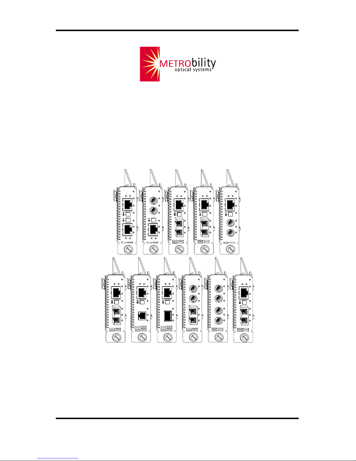
Models:R621-11 / R611-51 / R641-13 / R641-14 / R641-15 /
R641-17 / R641-1G / R641-1E / R641-1J / R641-53 /
R641-55 / R612-51 / R642-53 / R642-55
RADIANCE
10/100MBPS
INTERFACE LINE CARDS
FX
PWR
RX
RX
LK
LK
M
M
FL
TX
TX
10/100
M
M
RX
LK
TX
FX
L
H
II
x
PWR
100 FD
RX
LK
T
X
TX
10/100
RX
LK
TX
FX
M
M
II
x
PWR
100 FD
RX
LK
T
X
TX
10/100
RX
LK
TX
FX
M
M
II
x
PWR
100 FD
RX
LK
T
X
TX
10/100
PWR
RX
RX
LK
LK
M
M
FL
TX
TX
10/100
FX
M
M
II
x
PWR
100 FD
RX
RX
LK
LK
T
X
M
M
FL
TX
TX
10/100
II
x
II
x
PWR
100 FD
100 FD
RX
RX
LK
LK
T
X
T
X
TX
TX
10/100
RX
LK
TX
FX
M
M
II
x
PWR
100 FD
RX
LK
T
X
TX
10/100
FX
RX
LK
TX
M
M
II
x
PWR
100 FD
RX
LK
T
X
TX
10/100
RX
LK
TX
FX
S
M
II
x
PWR
100 FD
RX
LK
T
X
TX
10/100
RX
LK
TX
FX
E
L
H
II
x
PWR
100 FD
RX
LK
T
X
TX
10/100
Page 2

This publication is protected by the copyright laws of the United States and other countries, with all rights
reserved. No part of this publication may be reproduced, stored in a retrieval system, translated,
transcribed, or transmitted, in any form, or by any means manual, electric, electronic, electromagnetic,
mechanical, chemical, optical or otherwise, without prior explicit written permission of Metrobility Optical
Systems, Inc.
© 2001-02, 2004 Metrobility Optical Systems, Inc. All rights reserved. Printed in USA.
Radiance 10/100Mbps Interface Line Cards
Copper to Copper:
R621-11 ____ 10/100Base-TX to 10/100Base-TX
Copper to Fiber:
R641-13 ____ 10/100Base-TX to 100Base-FX multimode SC
R641-14 ____ 10/100Base-TX to 100Base-FX singlemode SC
R641-15 ____ 10/100Base-TX to 100Base-FX multimode ST
R641-17 ____ 10/100Base-TX to 100Base-FX singlemode SC (40 km)
R641-1E____ 10/100Base-TX to 100Base-FX multimode MT-RJ
R641-1G ___ 10/100Base-TX to 100Base-FX multimode VF-45
R641-1J ____ 10/100Base-TX to 100Base-FX singlemode SC (100 km)
R611-51 ____ 10Base-FL multimode ST to 10/100Base-TX
Copper to Fiber with LLCF:
R612-51 ____ 10Base-FL multimode ST to 10/100Base-TX
Fiber to Fiber:
R641-53 ____ 10Base-FL multimode ST to 100Base-FX multimode SC
R641-55 ____ 10Base-FL multimode ST to 100Base-FX multimode ST
Fiber to Fiber with LLCF:
R642-53 ____ 10Base-FL multimode ST to 100Base-FX multimode SC
R642-55 ____ 10Base-FL multimode ST to 100Base-FX multimode ST
Page 3

Table of Contents
Radiance 10/100Mbps Interface Line Cards Installation &
User Guide
Overview...............................................................................................................4
Installation Guide ................................................................................................6
STEP 1: Unpack the Line Card ..............................................................6
STEP 2: Set the Switches .......................................................................6
STEP 3: Install the Line Card ..............................................................12
STEP 4: Connect to the Network ......................................................... 13
User Guide ......................................................................................................... 15
LED Indicators .....................................................................................15
Factory Settings....................................................................................16
Link Loss Return (LLR) ......................................................................17
Link Loss Carry Forward (LLCF) .......................................................18
Topology Solutions .............................................................................. 19
Technical Specifications.......................................................................20
Product Safety, EMC and Compliance Statements ..............................22
Warranty and Servicing........................................................................23
Metrobility, Metrobility Optical Systems, AutoTwister, and NetBeacon are registered trademarks of
Metrobility Optical Systems, Inc. The Metrobility Optical Systems logo is a trademark of Metrobility
Optical Systems, Inc. All others are trademarks of their respective owners.
The information contained in this document is assumed to be correct and current. The manufacturer is
not responsible for errors or omissions and reserves the right to change specifications at any time
without notice.
Page 4

4
Overview
The Radiance 10/100Mbps interface line card provides seamless migration
between Ethernet and Fast Ethernet networks, in addition to built-in media
conversion allowing high-speed integration of fiber optic and twisted-pair
segments. A complete set of LEDs allows for quick status verification, and a
bank of DIP switches provides added versatility on each port. To optimize your
Ethernet network, each port operates independently in either half or full duplex.
The management functionality allows communication between the chassis and a
management station. This ability provides remote software control over the
Radiance line card configuration and notification of a failure to the management
station.
The Radiance 10/100Mbps interface line cards offer the following key features:
• Auto-negotiation switches on all twisted-pair interfaces.
• Link Loss Return (LLR) functionality to aid in troubleshooting a
remote network connection on all fiber optic ports.
• Link Loss Carry Forward (LLCF) functionality to aid in troubleshooting a remote network connection. (R642-xx and R612-51
only)
• An MDI-II to MDI-X switch that eliminates the need for crossover
cables on twisted-pair ports.
• Store-and-forward switching to improve overall network performance by buffering packets during times of heavy congestion and
to prevent the forwarding of corrupted packets.
• A high-performance switching engine that performs forwarding and
filtering at full wire speed (148,800 packets per second).
• The ability to learn up to 8,000 MAC addresses.
• 320 buffers per port with 1,536 bytes each.
• Low last-bit-in to first-bit-out delay.
Page 5

Radiance 10/100Mbps Interface Line Cards 5
For updating or expanding an existing network, Metrobility offers line cards that
support a wide range of configuration needs. The Radiance 10/100Mbps
interface line cards support the following conversion combinations:
10/100Base-TX to 10/100 Base TX
10/100Base-TX to 100Base-FX multimode SC
10/100Base-TX to 100Base-FX singlemode SC
10/100Base-TX to 100Base-FX multimode ST
10/100Base-TX to 100Base-FX multimode MT-RJ
10/100Base-TX to 100Base-FX multimode VF-45
10Base-FL multimode ST to 10/100 Base-TX
10Base-FL multimode ST to 100Base-FX multimode SC
10Base-FL multimode ST to 100Base-FX multimode ST
Page 6
6 Installation Guide
Installation Guide
Follow the simple steps outlined in this section to install and start using
your Radiance 10/100Mbps interface line card.
NOTE: Electrostatic discharge precautions should be taken when handling any
line card. Proper grounding is recommended (i.e., wear a wrist strap).
Unpack the Line Card
Your order has been provided with the safest possible packaging, but
shipping damage does occasionally occur. Inspect your line card
carefully. If you discover any shipping damage, notify your carrier and
follow their instructions for damage and claims. Save the original
shipping carton if return or storage of the unit is necessary.
Set the Switches
MDI-II to MDI-X Switch (twisted-pair ports only)
To eliminate the need for crossover cables, the Radiance 10/100Mbps
interface line card includes an MDI-II to MDI-X switch on each
twisted-pair port. This push-in switch is located in the center of the
front panel and allows setup in either straight-through or crossover
configurations. The default setting is parallel (II).
When setting the switch, observe the positioning of the following
symbols:
• The parallel symbol (II) indicates a straight-through or parallel
connection. The switch is up. (default)
• The cross symbol (X) indicates a crossover connection. The
switch is down.
Use the tables below as a guide.
1
2
A device that is wired straight through needs one crossover connection:
If the cable is
straight through
crossover
the MDI-II to MDI-X Switch Setting should be
X
II
A device that is wired crossover needs a parallel connection:
If the cable is
straight through
crossover
the MDI-II to MDI-X Switch Setting should be
II
X
Page 7
Radiance 10/100Mbps Interface Line Cards 7
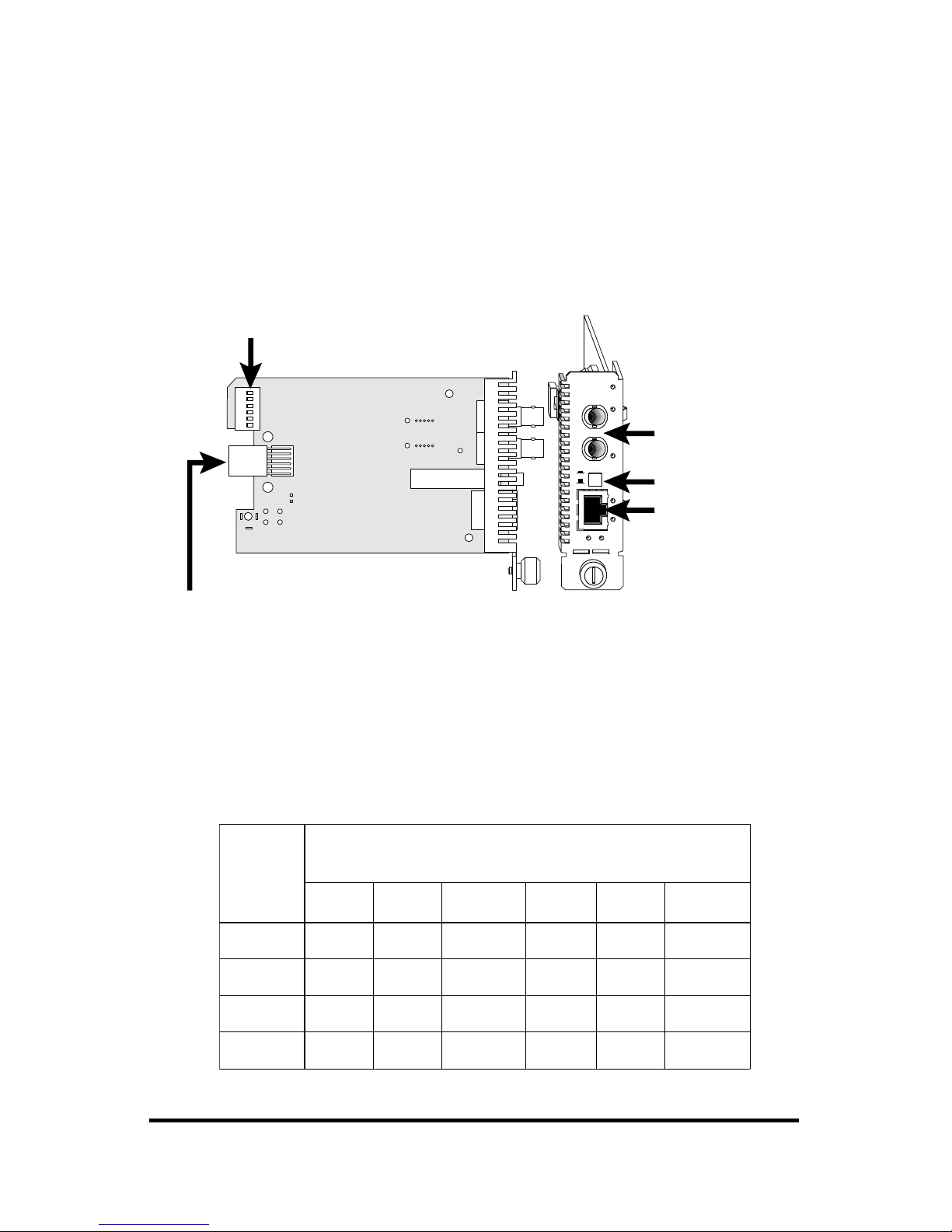
DIP Switches
A set of six DIP switches, located on the back of the line card, allows
you to select from several modes of operation. These switches are
clearly marked on the printed circuit board.
*DIP switches also can be managed via console commands or with Metrobility’s NetBeacon® or WebBeacon
management software. Refer to the
Command Line Interface Reference Guide, NetBeacon Element Management
Software Installation & User’s Guide
or
WebBeacon Management Software Installation & User’s Guide
for software
management information.
II
x
PWR
100 FD
RX
RX
LK
LK
TX
TX
10/100
DIP
switches
Power Connector
Port 1
MDI-II to MDI-X Switch
Port 2
When setting DIP switches,* the UP position is when the lever of the
DIP switch is pushed away from the circuit board. The DOWN position
is when the lever is pushed toward the circuit board.
NOTE: Not all switches are available on every model. Unmarked
switches are reserved and should be left in the DOWN position. See the
table below for switch locations on the four board types.
draoB
epyT
noitisoPhctiwSPID
)thgirottfel(
12 3 4 5 6
XT-XT1DF1NA1M0012DF2NA2M001
XT-LF1DF1RLLFCLL2DF2NA2M001
XF-LF1DF1RLLFCLL2DF2RLL —
XF-XT1DF1NA1M0012DF2RLLFCLL
Page 8

8 Installation Guide
Auto-Negotiation Switch (AN)
*
Switches AN1 and AN2 control the use of auto-negotiation on their
respective copper ports. To enable auto-negotiation, push the lever UP.
To disable this function, push the lever DOWN. The default setting is
auto-negotiation enabled.
When a port has auto-negotiation enabled, it advertises 10/100Mbps and
full/half duplex capabilities when both its speed (100M) and duplex
(FD) switches are also enabled. These are the default settings on a
copper port. If the 100M switch is disabled, the port advertises only
10Mbps capability. If the FD switch is disabled, the port advertises only
half duplex.
When auto-negotiation is disabled, the port’s duplex is determined by
its FD switch setting and its speed is set by its 100M switch.
10/100Mbps Switch (100M)
*
Switches 100M1 and 100M2 control the speed setting for their respective copper ports. The speed setting determines which speed is advertised when auto-negotiation is enabled. If auto-negotiation is disabled,
the port speed is the same as the switch setting, where UP is 100Mbps
and DOWN is 10Mbps.
When the 100M switch is UP, the port advertises 10/100Mbps capability if auto-negotiation is enabled. This is the default setting. If autonegotiation is disabled, the port’s speed is set to 100Mbps.
When the 100M switch is DOWN, the port advertises only 10Mbps
capability if auto-negotiation is enabled. If auto-negotiation is disabled,
the port’s speed is set to 10Mbps.
Half/Full Duplex Switch (FD)
*
For copper ports with auto-negotiation disabled and all fiber optic ports,
switches FD1 and FD2 determine the duplex mode of their respective
ports. A port operates at full duplex when its FD switch is UP. It
operates at half duplex when its FD switch is DOWN. The default is
full duplex enabled (UP).
With auto-negotiation enabled on a copper port, the port advertises full/
half duplex capability when its FD switch is UP. The port advertises
only half duplex when its FD switch is DOWN.
*
Changes to the AN, 100M and FD switch settings only come into effect after the power-cycle
initialization.
Page 9

Radiance 10/100Mbps Interface Line Cards 9
Link Loss Return Switch (LLR)
The 10/100Mbps interface line card incorporates Link Loss Return
(LLR) functionality as an aid in troubleshooting remote connections on
its fiber optic ports. When LLR is enabled, the loss of inbound link
pulses on a port stops the transmission of outbound link pulses on the
same port. For example, if LLR is enabled on port 2 and its receiver
(RX) stops detecting link pulses, then port 2’s transmitter (TX) will
stop sending link pulses. LLR is enabled on each fiber port independently. LLR is not applicable to copper ports.
Link Loss Return is enabled on Port 1 when switch LLR1 is UP, and it
is enabled on Port 2 when switch LLR2 is UP. The unit is shipped with
LLR disabled on both ports. Refer to Link Loss Return in the User
Guide section of this manual for more detailed information.
Link Loss Carry Forward Switch (LLCF)
In addition to LLR, the R612-51 and R642-xx units support Link Loss
Carry Forward functionality to help with troubleshooting remote
connections.
Unlike LLR, which only applies to fiber ports, LLCF affects both ports
on the card. When LLCF is enabled, the loss of inbound link pulses on
a port stops the transmission of outbound link pulses on the opposite
port. For example, if LLCF is enabled, the loss of incoming link pulses
at Port 1 stops the transmission of link pulses out of Port 2. Con-
versely, if Port 2 stops receiving link pulses, Port 1 will not transmit
link pulses.
Link Loss Carry Forward is enabled on both ports when switch LLCF
is UP. The unit is shipped with LLCF disabled. Refer to Link Loss
Carry Forward in the User Guide section of this manual for further
details.
Page 10

10 Installation Guide
noitarugifnoC
1troP2troP
1DF2DF
flaH01-flaH01
lluF01-flaH01PU
flaH001-lluF01PU
lluF001-lluF01 PU PU
noitarugifnoC
1troP2troP
1DF1NA1M0012DF2NA2M001
otuA-otuA PU PU PU PU PU PU
flaH01-flaH01
lluF01-flaH01PU
flaH001-flaH01PU
lluF001-flaH01PUPU
flaH01-lluF01PU
lluF01-lluF01PUPU
flaH001-lluF01PUPU
lluF001-lluF01PUPUPU
flaH01-flaH001PU
lluF01-flaH001PUPU
flaH001-flaH001PUPU
lluF001-flaH001PUPUPU
flaH01-lluF001PUPU
lluF01-lluF001PUPUPU
flaH001-lluF001PUPUPU
lluF001-lluF001PUPUPUPU
Use the following tables to help you set the DIP switches to obtain
specific modes of operation on the four board types. The configuration
column lists the speed and duplex options for Port 1 on the left and Port
2 on the right. “Auto” denotes that auto-negotiation is enabled. The
default settings are highlighted.
Table 1. TX to TX
Table 2. FL to FX
Page 11

Radiance 10/100Mbps Interface Line Cards 11
noitarugifnoC
1troP2troP
1DF1NA1M0012DF
lluF001-otuA PU PU PU PU
flaH001-otuAPUPUPU
flaH001-flaH01
lluF001-flaH01PU
flaH001-lluF01PU
lluF001-lluF01PUPU
flaH001-flaH001PU
lluF001-flaH001PUPU
flaH001-lluF001PUPU
lluF001-lluF001PUPUPU
Table 3. FL to TX
Table 4. TX to FX
Set the switches UP where indicated.
Set the switches DOWN for the blank positions.
noitarugifnoC
1troP2troP
1DF2DF2NA2M001
otuA-lluF01 PU PU PU PU
otuA-flaH01PUPUPU
flaH01-flaH01
lluF01-flaH01PU
flaH001-flaH01PU
lluF001-flaH01PUPU
flaH01-lluF01PU
lluF01-lluF01PUPU
flaH001-lluF01PUPU
lluF001-lluF01PUPUPU
Page 12

12 Installation Guide
3
• Insert the card into a slot on the chassis making sure that the
top and bottom edges of the board are aligned with the top and
bottom card guides in the chassis. Do not force the card into
the chassis unnecessarily. It should slide in easily and evenly.
• Slide the card in until the top and bottom edges of the front
panel are flush and even with the top and bottom edges of the
chassis.
• To secure the line card to the chassis, turn the thumbscrew
clockwise until it is snug. The card is now properly installed
and ready for connection to the network.
FX
PWR
RX
RX
LK
LK
M
M
FL
TX
TX
10/100
M
M
RX
LK
TX
FX
M
M
II
x
PWR
100 FD
RX
LK
T
X
TX
10/100
II
x
PWR
100 FD
RX
RX
LK
LK
T
X
M
M
FL
TX
TX
10/100
II
x
II
x
PWR
100 FD
100 FD
RX
RX
LK
LK
T
X
T
X
TX
TX
10/100
RX
LK
TX
FX
M
M
II
x
PWR
100 FD
RX
LK
T
X
TX
10/100
MGT-10
LK
AT
C
O
N
S
O
L
E
1
PWR
A
B
R
ER
FX
PWR
RX
RX
LK
LK
M
M
FL
TX
TX
10/100
M
M
PWR
RX
RX
LK
LK
M
M
FL
TX
TX
10/100
FX
M
M
PWR
M
M
OC-12
RXLK
LK
T
X
S
M
R
X
T
X
LX
LK
LK
PWR
1000BASE
S
M
SX
M
M
PWR
1000BASE
LK
LK
SX
M
M
LX
S
M
R
X
T
X
Card Guide
Card Guide
Slot for Management Card
Thumb Screw
Blank Panel
IMPORTANT!
Tighten thumb screw
to secure each card firmly
to chassis before making
network connections.
FX
PWR
RX
RX
LK
LK
M
M
FL
TX
TX
10/100
M
M
FX
PWR
RX
RX
LK
LK
M
M
FL
TX
TX
10/100
M
M
PWR
M
M
OC-12
RXLK
LK
T
X
S
M
R
X
T
X
PWR
M
M
OC-12
RXLK
LK
T
X
S
M
R
X
T
X
PWR
M
M
OC-12
RXLK
LK
T
X
S
M
R
X
T
X
PWR
M
M
OC-12
RXLK
LK
T
X
S
M
R
X
T
X
R
X
T
X
LK
PWR
M
M
10/100
LK
M
M
FL
FX
RX
TX
RX
TX
LK
AT
2
Install the Line Card
The Radiance line card offers the ease of plug-and-play installation and
is hot-swappable. The card must be firmly secured to the chassis before
network connections are made. Follow the simple steps outlined below
to install your line card.
• Grasp the card by the front panel as shown.
Page 13

Radiance 10/100Mbps Interface Line Cards 13
Connect to the Network
To connect the Radiance line card to the network, insert the fiber optic
or twisted-pair cables into the appropriate connectors. Port 1 is on the
top and Port 2 is on the bottom. Be sure the card is secured to the
chassis before making network connections. The table below shows
the correct connectors for Ports 1 and 2.
ledoMrotcennoC1troProtcennoC2troP
11-126R54-JR54-JR
31-146R54-JRCSedomitlumXF
41-146R
71-146R
J1-146R
54-JRCSedomelgnisXF
51-146R54-JRTSedomitlumXF
E1-146R54-JRJR-TMedomitlumXF
G1-146R54-JR54-FVedomitlumXF
15-116R
15-216R
TSedomitlumLF54-JR
35-146R
35-246R
TSedomitlumLFCSedomitlumXF
55-146R
55-246R
TSedomitlumLFTSedomitlumXF
4
Fiber Optic Connections
All models, except the R621-11, provide one or two fiber optic multimode or singlemode connectors. 10Base-FL segments are assigned to
Port 1, and 100Base-FX segments are assigned to Port 2.
Multimode fiber optic connectors support a maximum segment length
of 2 km for remote links.
The R641-14, -17, and -1J provide one set of FX singlemode SC
connectors. The R641-14 supports a maximum length of 20 km. The
R641-17 supports a maximum length of 40 km. The R641-1J supports a
maximum length of 100 km for remote links.
Page 14

14 Installation Guide
Insert the fiber optic connectors as shown below.
Once power is applied to the unit, verify correct connectivity via the
LK (link) LED.
RX
LK
TX
FX
M
M
II
x
PWR
100 FD
RX
LK
T
X
TX
10/100
RX
LK
TX
FX
M
M
II
x
PWR
100 FD
RX
LK
T
X
TX
10/100
RX
LK
TX
FX
M
M
II
x
PWR
100 FD
RX
LK
T
X
TX
10/100
RX
LK
TX
FX
M
M
II
x
PWR
100 FD
RX
LK
T
X
TX
10/100
II
x
PWR
100 FD
RX
RX
LK
LK
T
X
M
M
FL
TX
TX
10/100
II
x
II
x
PWR
100 FD
100 FD
RX
RX
LK
LK
T
X
T
X
TX
TX
10/100
RX
LK
TX
FX
M
M
II
x
PWR
100 FD
RX
LK
T
X
TX
10/100
RX
LK
TX
FX
M
M
II
x
PWR
100 FD
RX
LK
T
X
TX
10/100
FX
RX
LK
TX
M
M
II
x
PWR
100 FD
RX
LK
T
X
TX
10/100
MGT-10
LK
AT
C
O
N
S
O
L
E
1
PWR
A
B
R
ER
FX
PWR
RX
RX
LK
LK
M
M
FL
TX
TX
10/100
M
M
PWR
RX
RX
LK
LK
M
M
FL
TX
TX
10/100
FX
M
M
LK
AT
2
Twisted-Pair Connections
All models, excluding the R641-53, R641-55, R642-53 and R642-55,
provide one or two shielded RJ-45 connectors which support a maximum segment length of 100 meters. Use Category 3, 4 or 5 cables for
10Mbps segments; only use Category 5 cables for 100Mbps segments.
NOTE: Be sure to properly set the MDI-II to MDI-X switch located
between the two port connectors. Refer back to Step 2 if necessary.
Once power is applied to the line card, correct connectivity can be
verified via the LK (link) LED, if a device is connected to the remote
end of the cable.
Page 15

Radiance 10/100Mbps Interface Line Cards 15
User Guide
This section contains information regarding the operating features of the
Radiance 10/100Mbps interface line card.
LED Indicators
The Radiance 10/100Mbps interface line card provides several LEDs for the
visible verification of unit status and proper functionality. These LEDs can assist
with troubleshooting and overall network diagnosis and management. There are
separate TX, RX and LK indicators for each port. Each twisted-pair port also has
a 100 LED and an FD LED.
After power is applied to the card, verify correct connectivity via the LK LED.
DEL
lebaL
DEL
emaN)sutatS(roloC
noitcnuF
RWPrewop)ydaets(neerG.yllamrongninoitcnufdnaNOsitinuehT
KLknil)ydaets(neerG.knildilavasahtropehttahtseifireV
XTtimsnart)gniknilb(neerG.atadgnidnessitropehT
XReviecer)gniknilb(neerG.atadgniviecersitropehT
DFxelpud)ydaets(neerG
sitI.tilnehwedomxelpud-llufnisitropehT
ylnO(.tilnunehwedomxelpud-flahni
).stropriap-detsiwtrofelbaliava
001deeps)ydaets(neerG
spbM001sitropehtfognittesdeepsehT
ylnO(.tilnunehwspbM01sitI.tilnehw
).stropriap-detsiwtrofelbaliava
Page 16

16 User Guide
Factory Settings
Two functional settings on the Radiance 10/100Mbps interface line card are
preset and cannot be changed. Another setting, which controls the backpressure
function, can be modified via management software after the card is installed
and connected to the network. Refer to the Command Line Interface Reference
Guide, NetBeacon Element Management Software Installation and User’s Guide
or WebBeacon Management Software Installation and User’s Guide for detailed
software instructions.
Backpressure
For ports operating at half duplex, you have the option of enabling the
backpressure function. When backpressure is activated, the line card generates a
jamming pattern to force a collision on a port if the line card cannot allocate a
buffer for the port’s incoming packets. Activating backpressure enables it for
both ports. Backpressure is ignored in full duplex because collisions are not
generated in this mode. The default setting is disabled.
1522 Enable
The line card is preset to pass up to 1522-byte packets, which are used as VLAN
tags, through both ports. Packets that are too small (less than 64 bytes) or too
large (more than 1522 bytes) are discarded. This setting cannot be modified.
Back-Off
Packet transmission is attempted 16 consecutive times before the 10/100Mbps
interface line card restarts its back-off algorithm. After the back-off period ends,
the card again tries to send the packet up to 16 consecutive times. A packet
which endlessly fails to be sent will continue to be retransmitted forever, only
changing back-off intervals.
Page 17

Radiance 10/100Mbps Interface Line Cards 17
Link Loss Return (LLR)
The fiber optic ports of the Radiance line cards have been designed with LLR
*
for troubleshooting a remote connection.
When LLR is enabled, the fiber port’s transmitter shuts down if its receiver fails
to detect a valid receive link. LLR should only be enabled on one end of the link
and is typically enabled on either the unmanaged or remote device.
The diagram below shows a typical network configuration with a good link
status using Radiance line cards for remote connectivity.
*Units are shipped with the LLR function disabled (DOWN).
PC
Remote
Station
Switch/Hub
w/SNMP
Switch/Hub
w/SNMP
Radiance
Line Card
Fiber
Cable
LED lit = established link LED unlit = no link
LLR is OFF
LLR is ON
Radiance
Line Card
If one of the optical conductors is bad (as shown in the diagram box below), the
line card with LLR enabled will return a no link condition to its link partner.
This aids the administrator in determining the source of the loss.
PC
Remote
Station
Switch/Hub
w/SNMP
Switch/Hub
w/SNMP
Link Loss Returned
LED lit = established link LED unlit = no link
Broken
Fiber
Conductor
LLR is OFF LLR is ON
Radiance
Line Card
Radiance
Line Card
IMPORTANT: LLR must not be active on both ends of a configuration. If it is,
the link can never be established.
Page 18

18 User Guide
Link Loss Carry Forward (LLCF)
*
The R642-xx and R612-51 line cards incorporate LLCF for troubleshooting a
remote connection. When LLCF is enabled, the ports do not transmit a link
signal until they receive a link signal from the opposite port.
The diagram below shows a typical network configuration with a good link
status using Radiance line cards for remote connectivity. Note that LLCF is
enabled as indicated in the diagram.
Management
Station
Management
Station
Switch/Hub
w/SNMP
Switch/Hub
w/SNMP
Radiance
Line Card
Radiance
Line Card
LED lit = established link LED unlit = no link
LLCF is ON LLCF is ON
Remote
Cable
If a connection breaks, the line cards carry that link loss forward to the switch/
hubs which generate a trap to the management stations. A network administrator
can then determine the source of the problem.
Link Loss Carried Forward Link Loss Carried Forward
LED lit = established link LED unlit = no link
Management
Station
Management
Station
Switch/Hub
w/SNMP
Switch/Hub
w/SNMP
Radiance
Line Card
Radiance
Line Card
LLCF is ON LLCF is ON
Broken
Remote
Cable
Link Loss Carried Forward
LED lit = established link LED unlit = no link
Management
Station
Management
Station
Switch/Hub
w/SNMP
Switch/Hub
w/SNMP
Radiance
Line Card
Radiance
Line Card
LLCF is ON LLCF is ON
Broken
Cable
Remote
Cable
Important: When connecting a line card with LLCF enabled to an autonegotiating device, force both sides of the configuration to 10Mbps and either
full or half duplex. This allows the line card to immediately see link pulses and
start passing data.
* Units are shipped with LLCF disabled (OFF).
Page 19

Radiance 10/100Mbps Interface Line Cards 19
Topology Solutions
100Mbps Enterprise Switch
F/O Links
Twisted-pair Links
10/100Mbps Hub
Radiance Central
Service Platform with
10/100Mbps Line Cards
AutoTwister¤
Servers with
100Mbps NICs
10Mbps Workgroup Hub
copper or fiber FDX
2km mm fiber
2km mm fiber
20km, 40km or 100km sm fiber
mm or sm fiber
copper HDX
10/100Mbps Switch
AutoTwister¤
AutoTwister¤
AutoTwister¤
AutoTwister¤
Page 20

20 User Guide
T echnical Specifications
Network Connections
Twisted-Pair Interface
Connector __________________________________ Shielded RJ-45, 8-pin jack
Impedance________________________________________ 100 ohms nominal
Signal Level Output (differential) __________________________ .95 to 1.05 V
Signal Level Input _________________________________ 350 mV minimum
Supported Link Length________________________________________ 100 m
Cable Type (10Mbps segments) __________________ Category 3, 4 or 5 UTP
(100Mbps segments) _______________________ Category 5 UTP
(For NEBS Level III and EN55024:1998 compliance, use only
Category 5 STP cables.)
Multimode Fiber Optic Interface
Connector ___________________________________ ST, SC, MT-RJ or VF-45
Wavelength _______________________________________________ 1310 nm
RX Input Sensitivity ________________________________ -31 dBm minimum
Output Power ______________________ -14 dBm to -23.5 dBm (50/125 µm)
______________________ -14 dBm to -20 dBm (62.5/125 µm)
Supported Link Length___________________________ up to 2 km full duplex
Cable Type ________________________________ 50/125 or 62.5/125 µm F/O
Singlemode Fiber Optic Interface
Connector _____________________________________________________SC
Wavelength _______________________________________________ 1310 nm
RX Input Sensitivity ________________________________ -35 dBm minimum
Output Power ____________________________________ -8 dBm to -15 dBm
Supported Link Length_______________________________ 20 km full duplex
Cable Type ___________________________________________ 9/125 µm F/O
Singlemode Fiber Optic Interface — long haul distance support
Connector _____________________________________________________SC
Wavelength _______________________________________________ 1310 nm
RX Input Sensitivity ________________________________ -35 dBm minimum
Output Power ______________________________________ 0 dBm to -5 dBm
Supported Link Length_______________________________ 40 km full duplex
Cable Type ___________________________________________ 9/125 µm F/O
Page 21

Radiance 10/100Mbps Interface Line Cards 21
Singlemode Fiber Optic Interface — extended long haul distance support
Connector _____________________________________________________SC
Wavelength _______________________________________________ 1550 nm
RX Input Sensitivity ________________________________ -37 dBm minimum
Output Power ______________________________________ 0 dBm to -3 dBm
Supported Link Length______________________________ 100 km full duplex
Cable T ype ___________________________________________ 9/125 µm F/O
Data Rate
Data Rate _______ 100 Mbps half duplex; 200 Mbps full duplex (Fast Ethernet)
_____________10 Mbps half duplex; 20 Mbps full duplex (Ethernet)
Latency _____________________________________ <9 µs (100 Mbps input)
*
____________________________________ <159 µs (10 Mbps input)
*
Power
R621-11 _______________________________________ 5 V @ 0.7 A, 3.5 W
R641-53, -55, -1J; R642-53, -55 _____________________ 5 V @ 1.1 A, 5.5 W
R611-51; R612-51; R641-13, -14, -15, -17, -1E, -1G _____ 5 V @ 0.9 A, 4.5 W
Environmental
Operating T emperature____________________________________ 0° to 50° C
Storage T emperature____________________________________ -30° to 70° C
Operating Humidity _________________________ 5% to 95% non-condensing
Weight_______________________________________________ 5 oz (0.14 kg)
*Only applicable to speeds less than 100% full duplex line rate.
Page 22

22 User Guide
Product Safety, EMC and Compliance
Statements
This equipment complies with the following requirements:
•UL
• CSA
• EN60950 (safety)
• FCC Part 15, Class A
• EN55022 Class A (emissions)
• EN55024: 1998 (immunity)
• IEC 825-1 Classification
• Class 1 Laser Product
• DOC Class A (emissions)
This product shall be handled, stored and disposed of in accordance with all governing
and applicable safety and environmental regulatory agency requirements.
The following FCC and Industry Canada compliance information is applicable
to North American customers only.
USA FCC Radio Frequency Interference Statement
This equipment has been tested and found to comply with the limits for a Class
A digital device, pursuant to Part 15 of the FCC Rules. These limits are designed
to provide reasonable protection against harmful interference when the equipment is operated in a commercial environment. This equipment generates, uses
and can radiate radio frequency energy, and if not installed and used in accordance with the instruction manual, may cause harmful interference to radio
communications. Operation of this equipment in a residential area is likely to
cause harmful interference in which case the user will be required to correct the
interference at his own expense.
Caution: Changes or modifications to this equipment not expressly approved by
the party responsible for compliance could void the user’s authority to operate
the equipment.
Canadian Radio Frequency Interference Statement
This Class A digital apparatus meets all requirements of the Canadian Interference-Causing Equipment Regulations.
Cet appareil numérique de la classe A respecte toutes les exigences du
Réglement sur le matériel brouilleur du Canada.
Page 23

Radiance 10/100Mbps Interface Line Cards 23
Warranty and Servicing
Three-Year Warranty for Radiance 10/100Mbps Interface Line Cards
Metrobility Optical Systems, Inc. warrants that every Radiance line card will be
free from defects in material and workmanship for a period of THREE YEARS
from the date of Metrobility shipment. This warranty covers the original user
only and is not transferable. Should the unit fail at any time during this warranty
period, Metrobility will, at its sole discretion, replace, repair, or refund the
purchase price of the product. This warranty is limited to defects in workmanship and materials and does not cover damage from accident, acts of God,
neglect, contamination, misuse or abnormal conditions of operation or handling,
including overvoltage failures caused by use outside of the product’s specified
rating, or normal wear and tear of mechanical components.
To establish original ownership and provide date of purchase, complete and
return the registration card or register the product online at
www.metrobility.com. If product was not purchased directly from Metrobility,
please provide source, invoice number and date of purchase.
To return a defective product for warranty coverage, contact Metrobility
Customer Service for a return materials authorization (RMA) number. Send the
defective product postage and insurance prepaid to the address provided to you
by the Metrobility Technical Support Representative. Failure to properly protect
the product during shipping may void this warranty. The Metrobility RMA
number must be clearly on the outside of the carton to ensure its acceptance.
Metrobility will pay return transportation for product repaired or replaced inwarranty. Before making any repair not covered by the warranty, Metrobility
will estimate cost and obtain authorization, then invoice for repair and return
transportation. Metrobility reserves the right to charge for all testing and
shipping costs incurred, if test results determine that the unit is without defect.
This warranty constitutes the buyer’s sole remedy. No other warranties, such as
fitness for a particular purpose, are expressed or implied. Under no circumstances will Metrobility be liable for any damages incurred by the use of this
product including, but not limited to, lost profits, lost savings, and incidental or
consequential damages arising from the use of, or inability to use, this product.
Authorized resellers are not authorized to extend any other warranty on
Metrobility’s behalf.
Page 24

Product Manuals
The most recent version of this manual is available online at
http://www.metrobility.com/support/manuals.htm
Product Registration
To register your product, go to
http://www.metrobility.com/support/registration.asp
25 Manchester Street, Merrimack, NH 03054 USA
tel: 1.603.880-1833 • fax: 1.603.594.2887
www.metrobility.com
5660-000012 G
3/04
 Loading...