

Page 1
RADIANCE
MULTI-RATE LINE CARD
MULTIRATE
PWR
RX
1
TX
SD
LB
BP
RX
2
TX
SD
LB
BP
Installation & User Guide
Model: R380-SS
Page 2

Radiance Multi-Rate Line Card
Line Card:
R380-SS ______ Multi-rate SFP to SFP
Small Form-Factor Pluggable (SFP) Multimode Optics:
O211-M5 ______ 1 Gbps SFP LC (multimode, 500 m)
O221-M5 ______ Multi-rate SFP LC (multimode, 1.06 Gbps to 2.125 Gbps, 500 m)
O280-M2 ______ Multi-rate SFP LC (multimode, 45 Mbps to 155 Mbps, 2 km) without
O292-M5 ______ Multi-rate SFP LC (multimode, 50 Mbps to 700 Mbps, 500 m) without
SFP Singlemode Optics:
O211-10 ______ 1 Gbps SFP LC (singlemode, 10 km)
O211-25 ______ 1 Gbps SFP LC (singlemode, 25 km)
O211-40 ______ 1 Gbps SFP LC (singlemode, 40 km)
O211-70 ______ 1 Gbps SFP LC (singlemode, 70 km)
O211-1A ______ 1 Gbps SFP LC (singlemode, 100 km)
O221-10 ______ Multi-rate SFP LC (singlemode, 1.06 Gbps to 2.125 Gbps, 10 km)
O281-40 ______ Fast Ethernet/OC-3 SFP LC (singlemode, 40 km)
O281-80 ______ Fast Ethernet/OC-3 SFP LC (singlemode, 80 km)
O283-20 ______ Multi-rate SFP LC (singlemode, 45 Mbps to 155 Mbps, 20 km)
O293-20 ______ Multi-rate SFP LC (singlemode, 125 Mbps to 622 Mbps, 20 km)
O2A3-10 ______ Multi-rate SFP LC (singlemode, 155 Mbps to 2.67 Gbps, 10 km)
SFP Bi-Directional Wavelength Division Multiplexing (BWDM) Optics:
O311-10-31 ____ 1 Gbps SFP SC (BWDM, 1310 nm TX / 1490 nm RX, 10 km)
O311-10-49 ____ 1 Gbps SFP SC (BWDM, 1490 nm TX / 1310 nm RX, 10 km)
O383-20-31 ____ Multi-rate SFP SC (BWDM, 10 Mbps to 155 Mbps, 1310 nm TX / 1550
O383-20-55 ____ Multi-rate SFP SC (BWDM, 10 Mbps to 155 Mbps, 1550 nm TX / 1310
digital diagnostics
digital diagnostics
nm RX, 20 km)
nm RX, 20 km)
SFP Coarse Wavelength Division Multiplexing (CWDM) Optics:
O411-80-31 ____ SFP LC (CWDM, 1.06 Gpbs to 1.25 Gbps, 1310 nm, 80 km)
O411-80-33 ____ SFP LC (CWDM, 1.06 Gpbs to 1.25 Gbps, 1330 nm, 80 km)
O411-80-35 ____ SFP LC (CWDM, 1.06 Gpbs to 1.25 Gbps, 1350 nm, 80 km)
O411-80-37 ____ SFP LC (CWDM, 1.06 Gpbs to 1.25 Gbps, 1370 nm, 40 km)
O411-80-39 ____ SFP LC (CWDM, 1.06 Gpbs to 1.25 Gbps, 1390 nm, 40 km)
O411-80-41 ____ SFP LC (CWDM, 1.06 Gpbs to 1.25 Gbps, 1410 nm, 80 km)
O411-80-43 ____ SFP LC (CWDM, 1.06 Gpbs to 1.25 Gbps, 1430 nm, 80 km)
O411-80-45 ____ SFP LC (CWDM, 1.06 Gpbs to 1.25 Gbps, 1450 nm, 80 km)
O411-80-47 ____ SFP LC (CWDM, 1.06 Gpbs to 1.25 Gbps, 1470 nm, 80 km)
O411-80-49 ____ SFP LC (CWDM, 1.06 Gpbs to 1.25 Gbps, 1490 nm, 80 km)
O411-80-51 ____ SFP LC (CWDM, 1.06 Gpbs to 1.25 Gbps, 1510 nm, 80 km)
O411-80-53 ____ SFP LC (CWDM, 1.06 Gpbs to 1.25 Gbps, 1530 nm, 40 km)
O411-80-55 ____ SFP LC (CWDM, 1.06 Gpbs to 1.25 Gbps, 1550 nm, 40 km)
O411-80-57 ____ SFP LC (CWDM, 1.06 Gpbs to 1.25 Gbps, 1570 nm, 80 km)
O411-80-59 ____ SFP LC (CWDM, 1.06 Gpbs to 1.25 Gbps, 1590 nm, 80 km)
O411-80-61 ____ SFP LC (CWDM, 1.06 Gpbs to 1.25 Gbps, 1610 nm, 80 km)
© 2004-2006 Metrobility Optical Systems, Inc. All rights reserved. Printed in USA.
Page 3

O413-40-47 ____ Multi-rate SFP LC (CWDM, 155 Mbps to 2.7 Gbps, 1470 nm, 40 km)
O413-40-49 ____ Multi-rate SFP LC (CWDM, 155 Mbps to 2.7 Gbps, 1490 nm, 40 km)
O413-40-51 ____ Multi-rate SFP LC (CWDM, 155 Mbps to 2.7 Gbps, 1510 nm, 40 km)
O413-40-53 ____ Multi-rate SFP LC (CWDM, 155 Mbps to 2.7 Gbps, 1530 nm, 40 km)
O413-40-55 ____ Multi-rate SFP LC (CWDM, 155 Mbps to 2.7 Gbps, 1550 nm, 40 km)
O413-40-57 ____ Multi-rate SFP LC (CWDM, 155 Mbps to 2.7 Gbps, 1570 nm, 40 km)
O413-40-59 ____ Multi-rate SFP LC (CWDM, 155 Mbps to 2.7 Gbps, 1590 nm, 40 km)
O413-40-61 ____ Multi-rate SFP LC (CWDM, 155 Mbps to 2.7 Gbps, 1610 nm, 40 km)
O413-80-47 ____ Multi-rate SFP LC (CWDM, 155 Mbps to 2.7 Gbps, 1470 nm, 80 km)
O413-80-49 ____ Multi-rate SFP LC (CWDM, 155 Mbps to 2.7 Gbps, 1490 nm, 80 km)
O413-80-51 ____ Multi-rate SFP LC (CWDM, 155 Mbps to 2.7 Gbps, 1510 nm, 80 km)
O413-80-53 ____ Multi-rate SFP LC (CWDM, 155 Mbps to 2.7 Gbps, 1530 nm, 80 km)
O413-80-55 ____ Multi-rate SFP LC (CWDM, 155 Mbps to 2.7 Gbps, 1550 nm, 80 km)
O413-80-57 ____ Multi-rate SFP LC (CWDM, 155 Mbps to 2.7 Gbps, 1570 nm, 80 km)
O413-80-59 ____ Multi-rate SFP LC (CWDM, 155 Mbps to 2.7 Gbps, 1590 nm, 80 km)
O413-80-61 ____ Multi-rate SFP LC (CWDM, 155 Mbps to 2.7 Gbps, 1610 nm, 80 km)
O483-80-47 ____ Multi-rate SFP LC (CWDM, 45 Mbps to 155 Mbps, 1470 nm, 80 km)
O483-80-49 ____ Multi-rate SFP LC (CWDM, 45 Mbps to 155 Mbps, 1490 nm, 80 km)
O483-80-51 ____ Multi-rate SFP LC (CWDM, 45 Mbps to 155 Mbps, 1510 nm, 80 km)
O483-80-53 ____ Multi-rate SFP LC (CWDM, 45 Mbps to 155 Mbps, 1530 nm, 80 km)
O483-80-55 ____ Multi-rate SFP LC (CWDM, 45 Mbps to 155 Mbps, 1550 nm, 80 km)
O483-80-57 ____ Multi-rate SFP LC (CWDM, 45 Mbps to 155 Mbps, 1570 nm, 80 km)
O483-80-59 ____ Multi-rate SFP LC (CWDM, 45 Mbps to 155 Mbps, 1590 nm, 80 km)
O483-80-61 ____ Multi-rate SFP LC (CWDM, 45 Mbps to 155 Mbps, 1610 nm, 80 km)
This publication is protected by the copyright laws of the United States and other countries, with all rights reserved. No
part of this publication may be reproduced, stored in a retrieval system, translated, transcribed, or transmitted, in any
form, or by any means manual, electric, electronic, electromagnetic, mechanical, chemical, optical or otherwise, without
prior explicit written permission of Metrobility Optical Systems, Inc.
Metrobility, Metrobility Optical Systems and NetBeacon are registered trademarks; the Metrobility Optical Systems logo
and WebBeacon are trademarks of Metrobility Optical Systems, Inc. Other trademarks appearing in this manual are the
property of their owners.
The information contained in this document is assumed to be correct and current. The manufacturer is not responsible for
errors or omissions and reserves the right to change specifications at any time without notice.
Page 4

Table of Contents
Radiance Multi-Rate Line Card Installation & User Guide
Overview............................................................................................................... 5
Installation Guide ................................................................................................. 8
Unpack the Line Card ............................................................................ 8
Set the DIP Switches ..............................................................................8
Configuring the Data Rate .............................................................. 9
Loopback (LBCK) Switch ............................................................10
Link Loss Carry Forward (LLCF) Switch .................................... 10
Link Loss Return (LLR) Switch ................................................... 10
Install the SFP Optics ........................................................................... 11
Install the Line Card.............................................................................12
Connect to the Network .......................................................................13
User Guide..........................................................................................................16
LED Operation .....................................................................................16
SFP Monitors ....................................................................................... 17
Loopback..............................................................................................18
Normal Operation .........................................................................18
Local Port Loopback.....................................................................18
Dual-Port Loopback......................................................................19
Link Loss Return..................................................................................20
Link Loss Carry Forward .....................................................................21
Topology Solutions ..............................................................................22
Coarse Wavelength Division Multiplexing (CWDM) ..................22
Changing the SFP Optics .....................................................................24
Technical Specifications.......................................................................25
Acronyms and Abbreviations...............................................................32
Product Safety, EMC and Compliance Statements..............................33
Warranty and Servicing........................................................................ 34
4
Page 5

Overview
The Radiance multi-rate line card with dual small form-factor pluggable
(SFP) optics provides a simple and versatile solution for converting between
two physical data formats. Use it to connect multimode to singlemode fiber, or
singlemode fiber with different wavelengths. A wide range of interchangeable
optics ensures the multi-rate line card will accommodate current and future
system needs regardless of the network’s data rate, protocol, or wavelength.
The multi-rate card supports a frequency range from 44.7 Mbps up to 2.7 Gbps,
however, it is not a rate adapter that converts from one protocol to another. Only
one data rate is configured manually through a set of DIP switches on the card,
automatically through software auto-detection, or by changing the settings via
software commands.
The card features loopback capability for testing link integrity, Link Loss Carry
Forward and Link Loss Return for troubleshooting remote connections, and a
clock and data recovery (CDR) circuit which can be bypassed for protocol
transparency. The CDR circuitry extracts the clock and data information from
the incoming stream and clears the signal from noise or jitter, which can
significantly compromise the transmission of error-free data. The hot-swappable
multi-rate line card is designed for use with the Radiance chassis system.
Compatible with the Coarse Wavelength Division Multiplexing (CWDM)
System, the multi-rate line card supports Metrobility’s CWDM pluggable optics
with wavelengths from 1310 up to 1610 nm. When installed in a managed
Radiance R5000 Central Service Platform, the multi-rate line card provides the
interface between the service provider’s switch and a wavelength-specific
connection to the mux/demux module in an R4000 chassis. At the customer site,
the multi-rate line card converts the specific wavelength back to a standard fiber
media that matches the customer’s equipment.
When configured with an R502-M management card, software management
over the multi-rate line card allows a system administrator to monitor and
configure the unit from a PC. Console commands, Metrobility’s NetBeacon® or
WebBeacon™ management software, or any standard SNMP application can be
used for management. Through software, the multi-rate line card delivers realtime monitoring of its internal temperature, SFP optical receive/transmit power
levels, and port link state, along with switch controls and other hardware data to
simplify troubleshooting and to ensure system stability.
Radiance Multi-Rate Line Card 5
Page 6
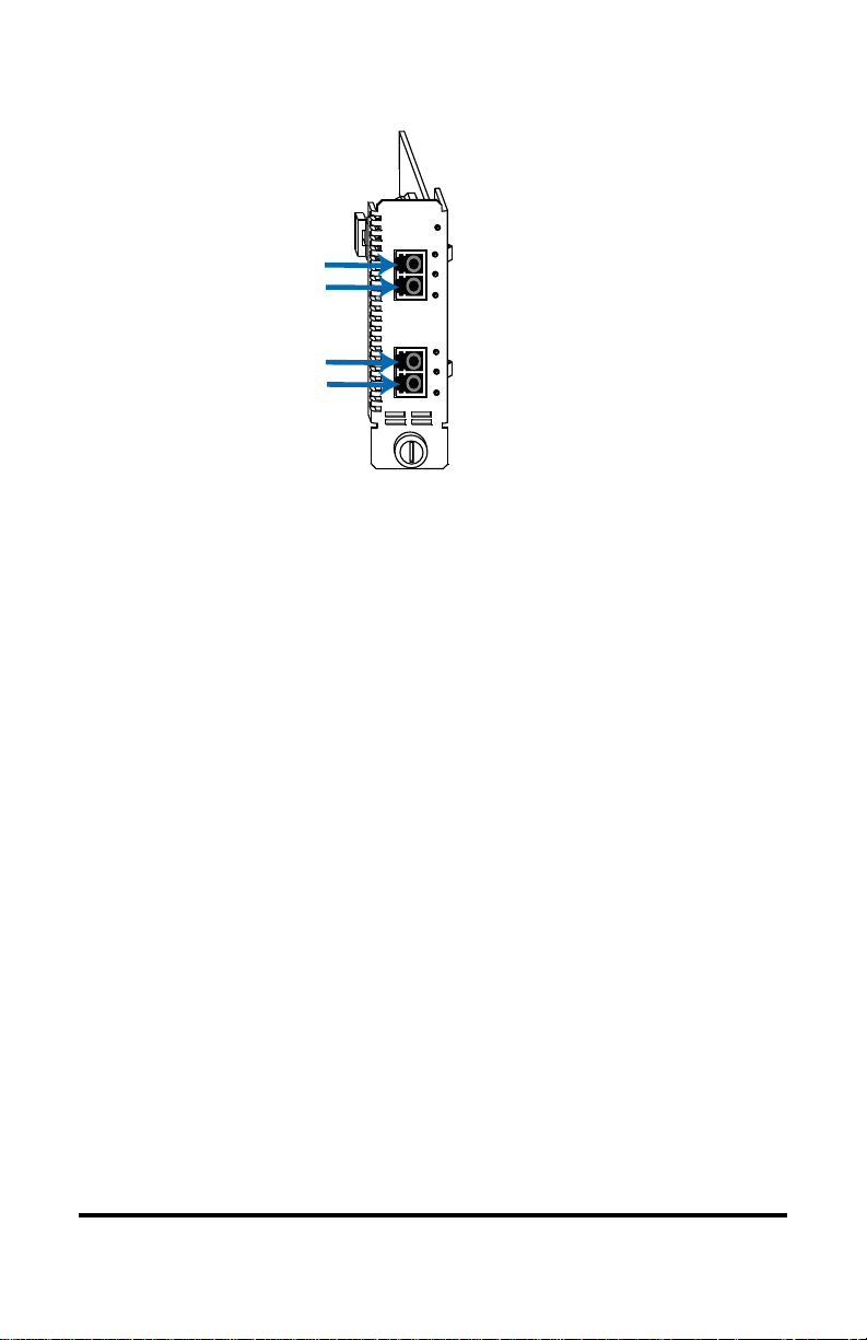
MULTIRATE
PWR
SD
Receiver
Transmitter
Receiver
Transmitter
RX
1
TX
RX
2
TX
LB
BP
SD
LB
BP
Port 1
Port 2
R380-SS
The Radiance multi-rate line card includes the following key features:
• Support for frequencies ranging from 44.7 Mbps up to 2.7 Gbps.
• Auto-detection or manual frequency settings.
• Temperature and optical power monitors.
• A wide range of SFP transceiver options compliant with Multi-Source Agreement (MSA) specifications.
• Full signal retiming, reshaping, and re-amplification (3 Rs) on both ports.
• Clock and data recovery (CDR) bypass capability for total protocol transparency.
• Independent loopback control on each port.
• Link Loss Carry Forward and Link Loss Return for troubleshooting remote
network connections.
• In-band management of a remote unit via SNMP.
• Hot-swappable board and optics.
6
Page 7

• Operates in any Metrobility chassis enclosure such as the Radiance R5000,
R1000, R400, R200, or RD-20.
• Manageable using Metrobility’s NetBeacon and WebBeacon element
management software, or any standard SNMP-based management
application.
Radiance Multi-Rate Line Card 7
Page 8
Installation Guide
Follow the steps outlined in this section to install and start using the Radiance
multi-rate line card.
NOTE: Electrostatic discharge precautions should be taken when handling any
line card. Proper grounding is recommended (i.e., wear a wrist strap).
Unpack the Line Card
Your order has been provided with the safest possible packaging, but
1
shipping damage does occasionally occur. Inspect your order carefully
for damage that may have occurred during shipment. If you discover
any shipping damage, notify your carrier and follow their instructions
for damage and claims. Save the original shipping carton if return or
storage of the unit is necessary.
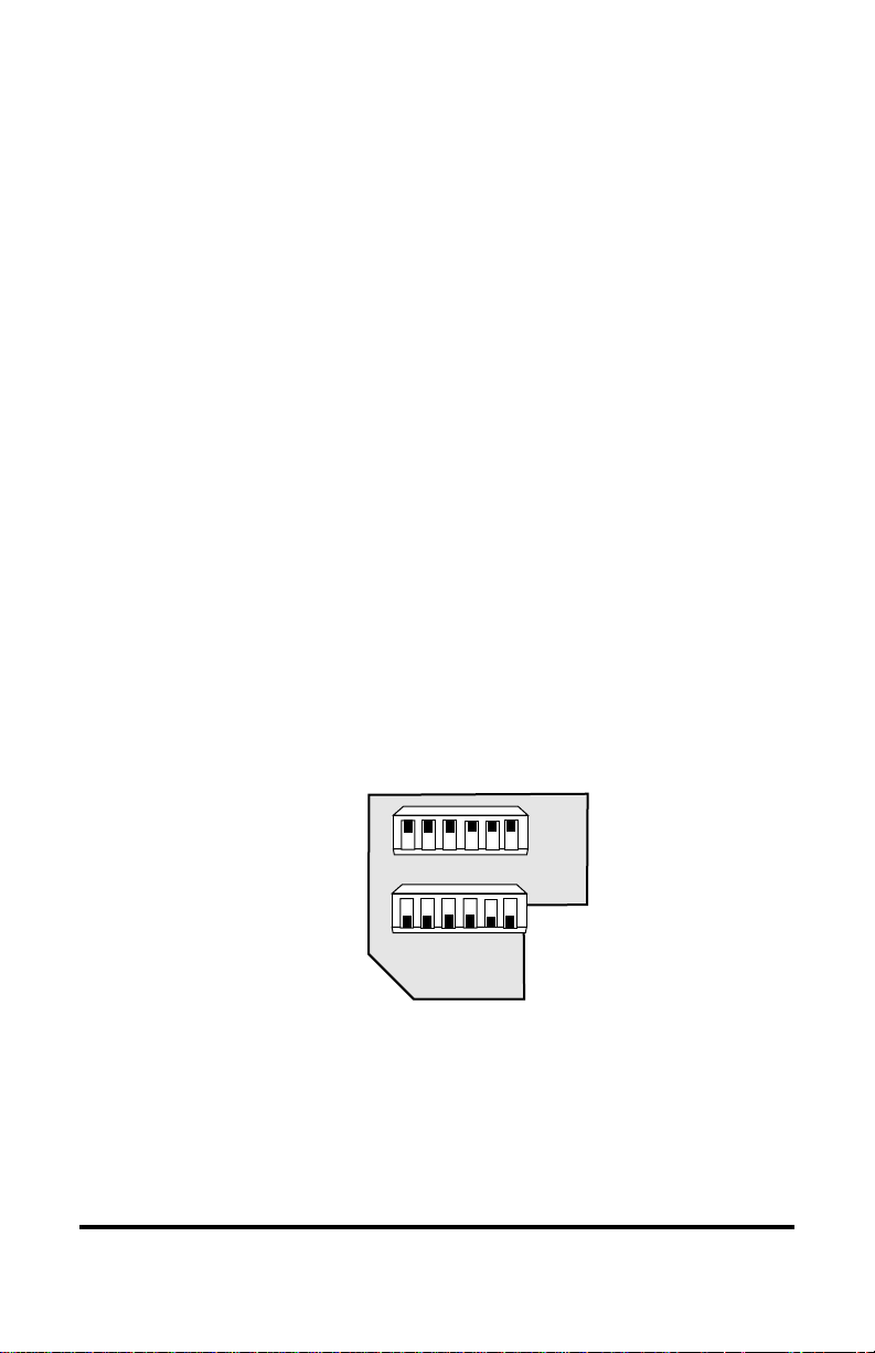
Set the DIP Switches
Two sets of 6-position DIP switches are provided on the R380 line
2
card. These switches, labeled SW1 and SW2, are used to enable/disable
functions or to set the initial data rate. The default settings for the two
banks of DIP switches are shown below.
Default DIP Switch Settings
L
L
C
F
SW2
SW1
or
WebBeacon Management
123456
L
L
L
L
L
B
L
B
R
C
R
C
1
K
2
K
1
2
When setting DIP switches*, the UP position is when the lever of the
switch is pushed away from the circuit board. The DOWN position is
when the lever of the switch is pushed toward the circuit board.
* DIP switches can also be managed via console commands or through Metrobility NetBeacon or
WebBeacon management software. Refer to the
NetBeacon Element Management Software Installation & User Guide
Software Installation & User Guide
8 Installation Guide
for software management information.
Command Line Interface Reference Guide
,
Page 9

Configuring the Data Rate
SW2 is used to set the initial data rate on the R380. The data rate is
determined by the 6-bit binary code derived from the position of the
DIP switches. The table below describes the settings supported by the
multi-rate line card. 1=UP, 0=DOWN. The default setting, which
automatically detects the data rate, is highlighted in yellow.
NOTE: The initial DIP switch setting may be overridden through software.
noitisoPhctiwSPID
123456
000000 ssapybRDClocotorpynA
100000 0637.443-SD
010000 0048.151-CO
110000 0000.521IDDF/tenrehtEtsaF
001000 5213.331331-CF
011000 0025.5511-MTS/3-CO
000100 0000.002002-NOCSE
100100 0526.662662-CF
001100 0052.135135-CF
011100 0080.2264-MTS/21-CO
111100 3415.666)CEF(4-MTS/21-CO
000010 0000.000,1devreseR
1000 10 0005.260,12601-CF
010010 0000.052,1tenrehtEtibagiG
10 10 10 0000.005,1devreseR
0 110 10 0000.000,2devreseR
1110 10 0000.521,25212-CF
000110 0000.052,2devreseR
100110 0000.573,2devreseR
010110 0023.884,261-MTS/84-CO
110110 0000.005,2devreseR
001110 0000.526,2devreseR
10 1110 0750.666,2)CEF(61-MTS/84-CO
1 1 1 1 1 1 otuA
,etaR
spbM
locotorP
tceted-otua,locotorpnwonknU
)TLUAFED(
Radiance Multi-Rate Line Card 9
Page 10

Loopback (LBCK) Switch
Loopback is enabled independently on each port. When loopback is
enabled, the port’s transmitter is connected to its receiver, thus returning incoming data back to the sender. Use LBCK1 to set loopback on
Port 1, and LBCK2 for Port 2. By default, LBCK is disabled (DOWN
position) for normal data transmission from one port to the other.
Refer to Loopback in the User Guide section for further details.
Link Loss Carry Forward (LLCF) Switch
Link Loss Carry Forward is provided as an aid in troubleshooting
remote connections. If the card loses link on one of its receivers, LLCF
will inhibit the transmission of link pulses out the opposite port. LLCF
applies to both ports.
For example, if LLCF is enabled and the multi-rate line card fails to
detect link on Port 2, the card will not transmit link pulses from Port 1.
In doing this, LLCF provides a way to extend the link loss indication
beyond a single segment.
LLCF is enabled when the LLCF switch is in the UP position. The unit
is shipped with LLCF disabled. For more information, refer to Link
Loss Carry Forward in the User Guide section.
Link Loss Return (LLR) Switch
The multi-rate line card offers Link Loss Return functionality as an
additional aid in troubleshooting remote connections. When LLR is
enabled on a port, loss of link by the port’s receiver stops its own
transmitter from sending out link pulses. LLR is enabled independently
on each port.
LLR1 enables/disables Link Loss Return on Port 1. LLR2 enables/
disables the function on Port 2 of the multi-rate line card. To enable
Link Loss Return, set the switch to the UP position. Set the switch
DOWN to disable the LLR. The unit is shipped with LLR disabled.
For more information, refer to Link Loss Return.
10 Installation Guide
Page 11

3
Install the SFP Optics
The R380 line card requires two small form-factor pluggable (SFP)
optics. Optics are shipped separately. The table below lists the recommended optics to use based on the network protocol and fiber type.
scitpOPFSdednemmoceR
locotorP
3-SD2M-082002-382Oxx-08-384O
0-MTS/1-CO2M-082002-382Oxx-08-384O
/tenrehtEtsaF
IDDF
1-MTS/3-CO2M-0820
NOCSE5M-292O
4-MTS/21-CO5M-292O
X1lennahCerbiF5M-1120
tenrehtEtibagiG5M-1120
X2lennahCerbiF5M-122001-122O
61-MTS/84-CO01-3A2O
edomitluMedomelgniSMDWBMDWC
2M-0820
04-182O
08-182O
02-3820
04-182O
08-182O
02-3820
02-392O
01-3A2O
02-392O
01-3A2O
xx-112O
01-3A2O
xx-112O
01-3A2O
01-122O
epyTrebiF
13-02-383O
55-02-383O
13-02-383O
55-02-383O
13-01-113O
94-01-113O
13-01-113O
94-01-113O
xx-08-384O
xx-08-384O
xx-04-314O
xx-08-314O
xx-04-314O
xx-08-314O
xx-04-314O
xx-08-314O
xx-08-114O
xx-04-314O
xx-08-314O
xx-04-314O
xx-08-314O
xx-04-314O
xx-08-314O
Before installing the SFP module, make sure the bail latch is closed, as
shown below. Do NOT open the bail.
SFP
CLOSED
BAIL LATCH
POSITION
SFP
DO NOT
OPEN
BAIL LATCH
To install the optics, align the SFP module so the receiver (▲) is
positioned above the transmitter (▼). For a BWDM module, align it so
the visible part of the circuit board located at the back of the module is
to the right. Slide the module into the empty slot. Push the SFP firmly
in place. Remove the protective covering on the connector.
Radiance Multi-Rate Line Card 11
Page 12

MULTIRATE
PWR
SD
RX
1
LB
TX
BP
SD
RX
2
LB
TX
BP
LKAT
RX
SEC
TX
IMPORTANT: The multi-rate line card is designed and tested to
operate using only Metrobility-supplied SFP transceivers. Safety,
performance, and reliability are guaranteed only when Metrobilitysupplied transceivers are used. Installing unspecified parts may
damage the product and will void the unit’s warranty.
Install the Line Card
The Radiance R380 offers the ease of plug-and-play installation and is
hot-swappable. The card must be secured firmly to the chassis before
making network connections. Follow the simple steps outlined below to
install the multi-rate line card.
• Grasp the card by the front panel as shown.
10/100
10/100
PWR
PWR
FL
100 FD
RX
RX
T
M
X
M
LK
LK
x
II
TX
TX
x
x
II
II
RX
RX
LK
LK
T
T
X
X
TX
TX
100 FD
100 FD
IMPORTANT!
Tighten thumb screw
to secure each card firmly
to chassis before making
network connections.
1000BASE
10/100
10/100
PWR
PWR
PWR
100 FD
100 FD
SX
RX
RX
T
T
M
X
X
M
LK
LK
x
x
II
TX
II
TX
LX
RX
RX
S
M
M
LK
M
LK
M
M
TX
TX
FX
FX
Thumb Screw
12 Installation Guide
10/100
PWR
PWR
FL
FL
RX
RX
M
M
LK
LK
TX
TX
RX
RX
M
LK
M
LK
TX
TX
FX
FX
Slot for Management Card
MGT-10
LK
1
AT
PWR
A
C
O
B
N
S
O
R
L
E
ER
Card Guide
10/100
OC-12
1000BASE
PWR
PWR
SX
LK
RXLK
LK
M
M
M
M
T
X
LX
LK
LK
LK
R
R
X
X
S
S
M
M
T
T
X
X
10/100
PWR
FL
RX
M
M
M
M
LK
TX
RX
M
M
LK
M
M
TX
FX
Card Guide
Blank Panel
Page 13

5
• Insert the card into a slot on the chassis making sure that the top and
bottom edges of the circuit board are aligned with the top and bottom
card guides in the chassis. Do not force the card into the chassis
unnecessarily. It should slide in easily and evenly.
• Slide the card in until the top and bottom edges of the front panel are
flush and even with the top and bottom edges of the chassis.
• Turn the thumbscrew clockwise until it is snug to secure the card to
the chassis. The card is now properly installed and ready for
connection to the network.
Connect to the Network
To connect the line card to the network, insert the fiber cables into the
appropriate connectors as illustrated below. Make sure the card is
secured to the chassis before making network connections. Once power
is applied to the unit, correct connectivity can be verified via the signal
detect (SD) LED, which should be lit.
100 BASE
LK
AT
LK
AT
1000 BASE
1
2
SW
LK
AT
LK
AT
100 BASE
redundant twister
PWR
SW
RESET
SECONDARY
LK
R
X
AT
T
X
100 BASE
redundant twister
PWR
SW
RESET
SECONDARY
LK
R
X
AT
T
X
MULTIRATE
“
PWR
MAIN
LK
AT
PRIMARY
LK
R
X
AT
T
X
“
MAIN
LK
AT
PRIMARY
LK
R
X
AT
T
X
LK
AT
SD
AT
1000 BASE
RESET
M
A
I
N
P
R
I
S
E
C
PWR
LK
AT
LK
AT
AT
SEC
100 BASE
redundant twister
PWR
SW
RESET
SECONDARY
LK
R
X
AT
T
X
“
MAIN
LK
AT
PRIMARY
LK
R
X
AT
T
X
100 BASE
PWR
R
LK
X
M
M
AT
T
X
R
X
S
M
T
X
Radiance Multi-Rate Line Card 13
Page 14

Model # Fiber Type Max Distance
O211-40 ........................... singlemode ...................................40 km
O211-70 ........................... singlemode ...................................70 km
O211-1A...........................singlemode .................................100 km
O221-M5.......................... multimode ....................................500 m
O221-10 ........................... singlemode ...................................10 km
O280-M2.......................... multimode ......................................2 km
O281-40 ........................... singlemode ...................................40 km
O281-80 ........................... singlemode ...................................80 km
O283-20 ........................... singlemode ...................................20 km
O292-M5.......................... multimode ....................................500 m
O293-20 ........................... singlemode ...................................20 km
O2A3-10 .......................... singlemode...................................10 km
O311-10-xx ...................... singlemode ...................................10 km
O383-20-xx ...................... singlemode ...................................20 km
O411-80-xx ...................... singlemode ...................................80 km
O413-40-xx ...................... singlemode ...................................40 km
O413-80-xx ...................... singlemode ...................................80 km
O483-80-xx ...................... singlemode ...................................80 km
For more information about optics, refer to Technical Specifications.
IMPORTANT: The distances noted are for reference purposes only.
The most important factor to achieve the desired distance is the optical
power budget. Metrobility specifications indicate the typical transmit
power budget. The actual distance is a function of the fiber type and
quality, the number and quality of splices, the type and quality of
connectors, the transmission loss, and other physical characteristics.
When making fiber optic connections, make sure that the optical
transmitter (TX) on the Radiance multi-rate line card connects to the
optical receiver on the connected device, and that the optical transmitter
on the device connects to the optical receiver (RX) on the Radiance card.
Use the SD LEDs on the front panel of the card to verify correct
segment connectivity. As you insert the cable into each port, the SD
LED will be lit if the following conditions are met:
• Power is being applied to the chassis.
• All connections are secure and the cables are undamaged.
• There is an active device connected to the other end of the
cable, and it is sending idle signals.
14 Installation Guide
Page 15

• The port’s receiver detects the presence of optical power and
the port’s CDR circuitry has locked onto the incoming signal.
For information on replacing the SFP transceiver, refer to Changing the
SFP Optics.
BWDM Interface
The bidirectional wavelength division multiplexed (BWDM) transceiver provides one singlemode SC connector. The O311-10-xx
supports a maximum segment length of 10 km; the O383-20-xx
supports a maximum segment length of 20 km. BWDM transceivers
must always be used in complementary pairs. That is, the O311-10-31
must be connected to the O311-10-49, and the O383-20-31 must be
connected to the O383-20-55.
The O311-10-31 transmits data at a wavelength of 1310 nm and
receives at 1490 nm. Correspondingly, the O311-10-49 transmits at
1490 nm and receives at 1310 nm. The O383-20-31 transmits at 1310
nm and receives at 1550 nm; the O383-20-55 transmits at 1550 nm and
receives at 1310 nm.
R380 with
O311-10-31
MULTIRATE
PWR
LK
RX
1
AT
TX
BP
SD
RX
2
AT
TX
MULTIRATE
PWR
LK
RX
1
AT
TX
BP
SD
RX
2
AT
TX
R380 with
O383-20-31
TX 1310 nm
RX 1490 nm
TX 1310 nm
RX 1550 nm
R380 with
O311-10-49
MULTIRATE
PWR
LK
RX
1
AT
TX
BP
TX 1490 nm
RX 1310 nm
SD
RX
2
AT
TX
up to 10 km
MULTIRATE
PWR
LK
RX
1
AT
TX
BP
TX 1550 nm
RX 1310 nm
SD
RX
2
AT
TX
R380 with
up to 20 km
O383-20-55
Radiance Multi-Rate Line Card 15
Page 16

User Guide
This section contains information regarding the operating features of the
Radiance multi-rate line card.
LED Operation
Several LEDs are visible on the front panel. These include the power (PWR),
signal detect (SD), loopback (LB), and bypass (BP) LEDs. There are separate
signal detect, loopback, and bypass LEDs for each port. Refer to the table below
for a description of each LED.
The function of each LED is as follows:
DEL
lebaL
RWPrewoP
DS
BLkcabpooL
PBssapyBRDC
langiS
/tceteD
Port 1
Port 2
emaNDEL
tceteDkcoL
/roloC
sutatS
neerG.tinuehtotdeilppusgniebsirewoP
FFO.rewopgniviecertonsitinU
neerG
wolleY
FFO
neerG
FFO
neerG
FFO.evitcasiRDCs'troP
MULTIRATE
PW
R
SD
RX
1
LB
TX
BP
SD
RX
2
LB
TX
BP
noitacidnI
sidnalangislacitponastcetedtroP
.tiotnodekcol
tub,langislacitponastcetedtroP
.tiotnokcoltonnac
lacitpoynatcetedtonseodtroP
.dellatsniPFSonsierehtro,langis
s'troP.edomkcabpoolnisitroP
nwostiotdetcennocsirettimsnart
.reviecer
rettimsnarts'troP.noitarepolamroN
.reviecers'troprehtootdetcennocsi
gniebsiyrtiucricRDCs'troP
.dessapyb
Power LED
Signal Detect LED
Loopback LED
Bypass LED
Signal Detect LED
Loopback LED
Bypass LED
16 User Guide
Page 17

SFP Monitors
Advanced management capabilities on the Radiance multi-rate line card enables
the monitoring of the following parameters for each SFP port transceiver with
digital diagnostics.
• Optical transmit power in dBm
• Optical receive power in dBm
• SFP transceiver’s internal temperature (range is -40° to +125° C)
These monitors can assist in ensuring optimal performance and system stability.
The SFP optics also provide useful information about the port interface.
• Connector type (e.g., LC or SC)
• Wavelength in nanometers
• Link length in meters supported by the SFP transceiver
* Refer to the
User Guide
Command Line Interface Reference Guide, NetBeacon Element Management Software Installation &
or
WebBeacon Management Software Installation & User Guide
for software management information.
Radiance Multi-Rate Line Card 17
Page 18

Loopback
The Radiance multi-rate line card features loopback testing capability to help
verify proper operation and to isolate problems within a particular segment of
the network. During loopback, the LBK LED is yellow. Loopback is enabled/
disabled in two ways: (1) setting the LBCK DIP switch(es), or (2) through
software by enabling loopback on Port 1 and/or 2. Once loopback is enabled, the
card remains in this mode until you reset the DIP switch or change the software
setting.
Normal Operation
During normal operation (loopback disabled), data from a local device enters the
local multi-rate line card through Port 1, passes through the fiber line between
the two cards, exits through Port 1 on the remote multi-rate line card, then enters
the remote device. The path is reversed for incoming data to the local device.
Local
Device
Local Multi-Rate
Line Card
Port
1
Port
2
Remote Multi-Rate
Line Card
Port
2
Port
1
Remote
Device
Local Port Loopback
Loopback can be applied individually to either port on a multi-rate line card.
The following diagrams illustrate the flow of data when loopback is enabled
independently on Port 1 and on Port 2.
Local
Device
Local
Device
Local Multi-Rate
Line Card
Port
1
Local Multi-Rate
Line Card
Port
1
Port
Port
2
Remote Multi-Rate
Line Card
Port
2
2
Remote Multi-Rate
Line Card
Port
2
Port
1
Port
1
Remote
Device
Remote
Device
18 User Guide
Page 19

Dual-Port Loopback
In this mode, data on both ports of the multi-rate line card are looped back to
their sending devices. Dual-port loopback is configurable through hardware or
software by enabling loopback on Port 1 and Port 2 simultaneously.
Local
Device
Local Multi-Rate
Line Card
Port
1
Port
2
Remote Multi-Rate
Line Card
Port
2
Port
Remote
Device
1
Radiance Multi-Rate Line Card 19
Page 20

Link Loss Return
Both ports on the Radiance multi-rate interface line card are designed with Link
Loss Return functionality for troubleshooting remote connections. When LLR is
enabled*, the port’s transmitter shuts down if its receiver fails to detect a valid
link signal. LLR should only be enabled on one end of a cable and is typically
enabled on either the unmanaged or remote device. LLR works in conjunction
with LLCF.
The diagram below shows a typical network configuration with good link status
using two Radiance multi-rate line cards for remote connectivity. Note that LLR
and LLCF are enabled as indicated in the diagram.
Management
Station
Switch/Hub
w/SNMP
Multi-Rate
Line Card A
LLCF is ON
LLR1 is ON
LLR2 is OFF
Port 1 Port 2
Remote
Cable
Multi-Rate
Line Card B
LLCF is ON
LLR2 is ON
LLR1 is OFF
Port 2 Port 1
Switch/Hub
w/SNMP
Remote
Station
LED lit = established link LED unlit = no link
If a connection breaks, the line cards will carry that link loss forward to a
switch/hub which generates a trap to the management station. The network
administrator can then determine the source of the problem.
Management
Station
Switch/Hub
w/SNMP
Link Loss Carried Forward
Multi-Rate
Line Card A
LLCF is ON
LLR1 is ON
LLR2 is OFF
Port 1
Link Loss Returned
LED lit = established link LED unlit = no link
Broken
Conductor
Multi-Rate
Line Card B
LLCF is ON
LLR2 is ON
LLR1 is OFF
Port 1
Link Loss Carried Forward
Switch/Hub
w/SNMP
Remote
Station
IMPORTANT:
20 User Guide
Page 21

Link Loss Carry Forward
The Radiance multi-rate line card incorporates LLCF to assist in troubleshooting
a remote connection. When LLCF is enabled*, the ports do not transmit a signal
until they receive a signal from the opposite port. When a lost link signal is
returned to an unmanaged line card, that lost link must then be carried forward
to a managed device (switch/hub) for trap generation.
The diagram below shows a typical network configuration with good link status
using two Radiance multi-rate line cards for remote connectivity. Note that
LLCF is enabled as indicated in the diagram.
Management
Station
Switch/Hub
w/SNMP
LED lit = established link LED unlit = no link
Multi-Rate
Line Card
LLCF is ON LLCF is ON
Remote
Cable
Multi-Rate
Line Card
Switch/Hub
w/SNMP
Management
Station
If a connection breaks, the line cards will carry that link loss forward to a
switch/hub which generates a trap to the management station. The network
administrator can then determine the source of the problem.
Management
Station
Management
Station
Switch/Hub
w/SNMP
LED lit = established link LED unlit = no link
Switch/Hub
w/SNMP
LED lit = established link LED unlit = no link
Multi-Rate
Line Card
LLCF is ON LLCF is ON
Link Loss Carried Forward Link Loss Carried Forward
Multi-Rate
Line Card
LLCF is ON LLCF is ON
Link Loss Carried Forward
Broken
Remote
Cable
Remote
Cable
Multi-Rate
Line Card
Multi-Rate
Line Card
Broken
Cable
Switch/Hub
w/SNMP
Switch/Hub
w/SNMP
Management
Station
Management
Station
NOTE: Loopback takes precedence over LLCF. If LLCF and loopback are both
enabled, LLCF functionality will be ignored for the port that is in loopback.
LLCF will remain in effect for the port that is not in loopback.
*Units are shipped with the LLCF disabled (DOWN).
Radiance Multi-Rate Line Card 21
Page 22

Topology Solutions
Servers
Switch
Radiance R5000 Central
Service Platform with
Multi-Rate Line Cards
Switch
PC running Network
Management Software
Workgroup Hub
remote connection
Enterprise Switch
Copper Links
Fiber Optic Links
Enterprise
Coarse Wavelength Division Multiplexing (CWDM)
Using the CWDM optics, the multi-rate line cards can be integrated into a
Radiance CWDM system, in which a single fiber pair carries data bidirectionally
on multiple wavelengths. In the following examples, each colored line represents a different wavelength. The network connections are shown in gray with
the magnification circles displaying the wavelengths carried on the lines.
Connections to the end user are shown in dark gray.
POINT TO POINT TOPOLOGY
Radiance R5000
with R380 Line Cards
Radiance R4000
with 8-Channel CWDM
Mux/Demux Modules
Radiance R4000
with 8-Channel CWDM
Mux/Demux Modules
Radiance R5000
with R380
Line Cards
22 User Guide
Page 23

RING TOPOLOGY
Radiance R5000
with R380 Line Cards
Radiance R4000
with OADM Modules
Radiance R4000
with OADM Modules
Drop & Pass
Radiance R1000
with R380
Line Card
Central
Office
Radiance R4000
with 4-Channel
CWDM Mux/Demux
Modules
Radiance R4000
with OADM Modules
Drop & Insert
with OADM Modules
Radiance R4000
Radiance R1000
with R380
Line Cards
Drop & Pass
Radiance R1000
with R380
Line Card
Drop & Insert
Radiance R1000
with R380 Line Cards
Drop & Pass
Radiance R1000
with R380 Line Card
Radiance Multi-Rate Line Card 23
Page 24

Changing the SFP Optics
T
The multi-rate line card supports two replaceable small form-factor pluggable
(SFP) transceivers. This section explains how to remove and install the optics on
the card. Metrobility SFP transceivers are hot-swappable.
IMPORTANT: Use only Metrobility-supplied SFP transceivers with this
product. Installing any other optics may damage the unit and will void the
product’s warranty.
1. Disconnect the fiber optic network cables, if they are installed, from both
the receiver (RX) and transmitter (TX) of the SFP transceiver.
WARNING: Avoid looking into the laser or cable.
2. To remove the SFP optics from the multi-rate line card, simply pull open the
release mechanism (i.e., plastic tab, release wire, etc.) and slide the module
out of the slot, as shown below, left.
MULTIRATE
PWR
RX
1
TX
RX
2
TX
RXTX
SD
LB
BP
SD
LB
BP
MULTIRATE
RX
1
TX
RX
2
TX
PWR
SD
SD
LB
BP
redundant twister
RESET
LB
SECONDARY
BP
R
X
T
X
100 BASE
PWR
SW
LK
R
X
AT
X
MAIN
PRIMARY
T
1000 BASE
“
RESET
LK
M
A
AT
I
N
P
LK
R
I
AT
S
E
C
SW
RELEASE
MEHCANISM
PWR
SEC
LK
AT
LK
AT
LK
AT
MULTIRATE
PWR
RX
1
TX
RX
2
TX
SD
LB
BP
SD
LB
BP
MULTIRATE
PWR
RX
1
TX
RX
2
TX
SD
BP
SD
LB
BP
LB
MULTIRATE
PWR
RX
1
TX
RX
2
TX
BWDM SFP
SD
LB
BP
SD
LB
BP
CIRCUI
BOARD
3. Align the new SFP module so the receiver (▲) is positioned above the
transmitter (▼). For a BWDM SFP, align it so the visible part of the circuit
board located at the back of the module is to the right.
4. Keeping the release mechanism in the closed position (bail latch should be
locked in place), slide the new SFP into the slot and push it firmly in place.
5. Remove the protective dust cover on the LC or SC connector.
6. Reconnect the network cables. Verify proper segment connectivity via the
green LK LED, which will be lit.
24 User Guide
Page 25

Technical Specifications
Data Rate ____________________44.7 Mbps to 2.7 Gbps, depending on optics
Power Requirements_______________________________ 5 V DC @ 1 A, 5 W
Environmental
Operating Temperature _____________________________________ 0 to 50° C
Storage Temperature _____________________________________ -30 to 70° C
Operating Humidity _________________________ 5% to 95% non-condensing
Weight_______________________________________________ 5 oz (0.14 kg)
Multimode Fiber Optic Plug-in (O211-M5)
Connector _____________________________________________________LC
Wavelength ________________________________________________ 850 nm
Data Rate ____________________________________ 1.06 Gbps to 1.25 Gbps
RX Input Sensitivity ____-19 dBm (min); -22 dBm (typical); 0 dBm (saturation)
Output Power ______________________-9 dBm to -3.5 dBm; -6 dBm (typical)
Typical Link Budget __________________________________________ 16 dB
Supported Link Length___________________________________ up to 500 m
Cable Type __________________________ 50/125 or 62.5/125 µm multimode
Multimode Fiber Optic Plug-in (O221-M5)
Connector _____________________________________________________LC
Wavelength ________________________________________________ 850 nm
Data Rate ___________________________________ 1.06 Gbps to 2.125 Gbps
RX Input Sensitivity ____-18 dBm (min); -22 dBm (typical); 0 dBm (saturation)
Output Power _______________________ -9 dBm to -3 dBm; -6 dBm (typical)
Typical Link Budget __________________________________________ 16 dB
Supported Link Length___________________________________ up to 500 m
Cable Type __________________________ 50/125 or 62.5/125 µm multimode
Multimode Fiber Optic Plug-in (O280-M2)
Connector _____________________________________________________LC
Wavelength _______________________________________________ 1310 nm
Data Rate _____________________________________ 45 Mbps to 155 Mbps
RX Input Sensitivity __ -32 dBm (min); -34 dBm (typical); -14 dBm (saturation)
Output Power ____________________ -19 dBm to -14 dBm; -17 dBm (typical)
Typical Link Budget __________________________________________ 17 dB
Supported Link Length____________________________________ up to 2 km
Cable Type __________________________ 50/125 or 62.5/125 µm multimode
Radiance Multi-Rate Line Card 25
Page 26

Multimode Fiber Optic Plug-in (O292-M5)
Connector _____________________________________________________LC
Wavelength _______________________________________________ 1310 nm
Data Rate _____________________________________ 50 Mbps to 700 Mbps
RX Input Sensitivity __ -26 dBm (min); -28 dBm (typical); -14 dBm (saturation)
Output Power ____________________ -20 dBm to -14 dBm; -18 dBm (typical)
Typical Link Budget __________________________________________ 10 dB
Supported Link Length_________ up to 500 m @ 622 Mbps, 2 km @ 156 Mbps
Cable Type __________________________ 50/125 or 62.5/125 µm multimode
Singlemode Fiber Optic Plug-in (O311-10-49) for BWDM
Connector _____________________________________________________ SC
TX W avelength____________________________________________ 1490 nm
RX Wavelength____________________________________________ 1310 nm
Data Rate ____________________________________ 1.06 Gbps to 1.25 Gbps
RX Input Sensitivity ___ -22 dBm (min); -24 dBm (typical); -3 dBm (saturation)
Output Power _______________________ -9 dBm to -3 dBm; -6 dBm (typical)
Typical Link Budget __________________________________________ 18 dB
Supported Link Length___________________________________ up to 10 km
Cable T ype _____________________________________9/125 µm singlemode
Singlemode Fiber Optic Plug-in (O311-10-31) for BWDM
Connector _____________________________________________________ SC
TX W avelength____________________________________________ 1310 nm
RX Wavelength____________________________________________ 1490 nm
Data Rate ____________________________________ 1.06 Gbps to 1.25 Gbps
RX Input Sensitivity ___ -22 dBm (min); -24 dBm (typical); -3 dBm (saturation)
Output Power _______________________ -9 dBm to -3 dBm; -6 dBm (typical)
Typical Link Budget __________________________________________ 18 dB
Supported Link Length___________________________________ up to 10 km
Cable T ype _____________________________________9/125 µm singlemode
Singlemode Fiber Optic Plug-in (O383-20-31) for BWDM
Connector _____________________________________________________ SC
TX W avelength____________________________________________ 1310 nm
RX Wavelength____________________________________________ 1550 nm
Data Rate _____________________________________ 10 Mbps to 155 Mbps
RX Input Sensitivity ___ -28 dBm (min); -30 dBm (typical); -8 dBm (saturation)
Output Power _____________________ -14 dBm to -8 dBm; -11 dBm (typical)
Typical Link Budget __________________________________________ 19 dB
Supported Link Length___________________________________ up to 20 km
Cable T ype _____________________________________9/125 µm singlemode
26 User Guide
Page 27

Singlemode Fiber Optic Plug-in (O383-20-55) for BWDM
Connector _____________________________________________________ SC
TX W avelength____________________________________________ 1550 nm
RX Wavelength____________________________________________ 1310 nm
Data Rate _____________________________________ 10 Mbps to 155 Mbps
RX Input Sensitivity ___ -28 dBm (min); -30 dBm (typical); -8 dBm (saturation)
Output Power _____________________ -14 dBm to -8 dBm; -11 dBm (typical)
Typical Link Budget __________________________________________ 19 dB
Supported Link Length___________________________________ up to 20 km
Cable T ype _____________________________________9/125 µm singlemode
Singlemode Fiber Optic Plug-in (O211-10)
Connector _____________________________________________________LC
Wavelength _______________________________________________ 1310 nm
Data Rate ____________________________________ 1.06 Gbps to 1.25 Gbps
RX Input Sensitivity ___ -20 dBm (min); -23 dBm (typical); -3 dBm (saturation)
Output Power ______________________-9.5 dBm to -3 dBm; -6 dBm (typical)
Typical Link Budget __________________________________________ 17 dB
Supported Link Length___________________________________ up to 10 km
Cable T ype _____________________________________9/125 µm singlemode
Singlemode Fiber Optic Plug-in (O211-25)
Connector _____________________________________________________LC
Wavelength _______________________________________________ 1310 nm
Data Rate ____________________________________ 1.06 Gbps to 1.25 Gbps
RX Input Sensitivity ____________________ -21 dBm (min), -23 dBm (typical)
Output Power _________________________ 0 dBm to 5 dBm; 2 dBm (typical)
Typical Link Budget __________________________________________ 25 dB
Supported Link Length___________________________________ up to 25 km
Cable T ype _____________________________________9/125 µm singlemode
Singlemode Fiber Optic Plug-in (O211-40)
Connector _____________________________________________________LC
Wavelength _______________________________________________ 1550 nm
Data Rate ____________________________________ 1.06 Gbps to 1.25 Gbps
RX Input Sensitivity ___ -24 dBm (min); -26 dBm (typical); -3 dBm (saturation)
Output Power ______________________ -5 dBm to 0 dBm; -2.5 dBm (typical)
Typical Link Budget _________________________________________ 23.5 dB
Supported Link Length___________________________________ up to 40 km
Cable T ype _____________________________________9/125 µm singlemode
Radiance Multi-Rate Line Card 27
Page 28

Singlemode Fiber Optic Plug-in (O211-70)
Connector _____________________________________________________LC
Wavelength _______________________________________________ 1550 nm
Data Rate ____________________________________ 1.06 Gbps to 1.25 Gbps
RX Input Sensitivity ___ -24 dBm (min); -26 dBm (typical); -3 dBm (saturation)
Output Power _________________________ 0 dBm to 5 dBm; 2 dBm (typical)
Typical Link Budget __________________________________________ 28 dB
Supported Link Length___________________________________ up to 70 km
Cable T ype _____________________________________9/125 µm singlemode
Singlemode Fiber Optic Plug-in (O211-1A)
Connector _____________________________________________________LC
Wavelength _______________________________________________ 1550 nm
Data Rate ____________________________________ 1.06 Gbps to 1.25 Gbps
RX Input Sensitivity ___ -32 dBm (min); -34 dBm (typical); -3 dBm (saturation)
Output Power _________________________ 0 dBm to 5 dBm; 2 dBm (typical)
Typical Link Budget __________________________________________ 36 dB
Supported Link Length__________________________________ up to 100 km
Cable T ype _____________________________________9/125 µm singlemode
Singlemode Fiber Optic Plug-in (O221-10)
Connector _____________________________________________________LC
Wavelength _______________________________________________ 1310 nm
Data Rate ___________________________________ 1.06 Gbps to 2.125 Gbps
RX Input Sensitivity ____-21 dBm (min); -23 dBm (typical); 0 dBm (saturation)
Output Power ______________________-9.5 dBm to -3 dBm; -6 dBm (typical)
Typical Link Budget __________________________________________ 17 dB
Supported Link Length___________________________________ up to 10 km
Cable T ype _____________________________________9/125 µm singlemode
Singlemode Fiber Optic Plug-in (O281-40)
Connector _____________________________________________________LC
Wavelength _______________________________________________ 1310 nm
Data Rate ____________________________________ 125 Mbps to 155 Mbps
RX Input Sensitivity __ -34 dBm (min); -36 dBm (typical); -10 dBm (saturation)
Output Power ______________________ -5 dBm to 0 dBm; -2.5 dBm (typical)
Typical Link Budget _________________________________________ 33.5 dB
Supported Link Length___________________________________ up to 40 km
Cable T ype _____________________________________9/125 µm singlemode
28 User Guide
Page 29

Singlemode Fiber Optic Plug-in (O281-80)
Connector _____________________________________________________LC
Wavelength _______________________________________________ 1550 nm
Data Rate ____________________________________ 125 Mbps to 155 Mbps
RX Input Sensitivity __ -34 dBm (min); -36 dBm (typical); -10 dBm (saturation)
Output Power ______________________ -5 dBm to 0 dBm; -2.5 dBm (typical)
Typical Link Budget _________________________________________ 33.5 dB
Supported Link Length___________________________________ up to 80 km
Cable T ype _____________________________________9/125 µm singlemode
Singlemode Fiber Optic Plug-in (O283-20)
Connector _____________________________________________________LC
Wavelength _______________________________________________ 1310 nm
Data Rate _____________________________________ 45 Mbps to 155 Mbps
RX Input Sensitivity ___ -28 dBm (min); -32 dBm (typical); -8 dBm (saturation)
Output Power ____________________-15 dBm to -8 dBm; -11.5 dBm (typical)
Typical Link Budget _________________________________________ 20.5 dB
Supported Link Length___________________________________ up to 20 km
Cable T ype _____________________________________9/125 µm singlemode
Singlemode Fiber Optic Plug-in (O293-20)
Connector _____________________________________________________LC
Wavelength _______________________________________________ 1310 nm
Data Rate ____________________________________ 125 Mbps to 622 Mbps
RX Input Sensitivity _ -28 dBm (min); -30.5 dBm (typical); -8 dBm (saturation)
Output Power ____________________-15 dBm to -8 dBm; -11.5 dBm (typical)
Typical Link Budget __________________________________________ 19 dB
Supported Link Length___________________________________ up to 20 km
Cable T ype _____________________________________9/125 µm singlemode
Singlemode Fiber Optic Plug-in (O2A3-10)
Connector _____________________________________________________LC
Wavelength _______________________________________________ 1310 nm
Data Rate ____________________________________ 155 Mbps to 2.67 Gbps
RX Input Sensitivity ____-20 dBm (min); -22 dBm (typical); 0 dBm (saturation)
Output Power ______________________ -10 dBm to -3 dBm; -6 dBm (typical)
Typical Link Budget __________________________________________ 16 dB
Supported Link Length___________________________________ up to 10 km
Cable T ype _____________________________________9/125 µm singlemode
Radiance Multi-Rate Line Card 29
Page 30

Singlemode Fiber Optic Plug-in (O411-80-31 to -45) for CWDM
Connector _____________________________________________________LC
Wavelength __________________________________ (see tables on next page)
Data Rate ____________________________________ 1.06 Gbps to 1.25 Gbps
RX Input Sensitivity ____-24 dBm (min); -26 dBm (typical); 0 dBm (saturation)
Output Power _________________________ 0 dBm to 5 dBm; 2 dBm (typical)
Typical Link Budget __________________________________________ 28 dB
Supported Link Length___________________________________ up to 80 km
Cable T ype _____________________________________9/125 µm singlemode
Singlemode Fiber Optic Plug-in (O411-80-47 to -61) for CWDM
Connector _____________________________________________________LC
Wavelength __________________________________ (see tables on next page)
Data Rate ____________________________________ 1.06 Gbps to 1.25 Gbps
RX Input Sensitivity ____-23 dBm (min); -25 dBm (typical); 0 dBm (saturation)
Output Power _________________________ 0 dBm to 5 dBm; 2 dBm (typical)
Typical Link Budget __________________________________________ 27 dB
Supported Link Length___________________________________ up to 80 km
Cable T ype _____________________________________9/125 µm singlemode
Singlemode Fiber Optic Plug-in (O413-40-xx) for CWDM
Connector _____________________________________________________LC
Wavelength __________________________________ (see tables on next page)
Data Rate _____________________________________ 155 Mbps to 2.7 Gbps
RX Input Sensitivity ____-20 dBm (min); -22 dBm (typical); 0 dBm (saturation)
Output Power _____________________ 0 dBm to +4 dBm; +1.5 dBm (typical)
Typical Link Budget _________________________________________ 23.5 dB
Supported Link Length___________________________________ up to 40 km
Cable T ype _____________________________________9/125 µm singlemode
Singlemode Fiber Optic Plug-in (O413-80-xx) for CWDM
Connector _____________________________________________________LC
Wavelength __________________________________ (see tables on next page)
Data Rate _____________________________________ 155 Mbps to 2.7 Gbps
RX Input Sensitivity ___ -30 dBm (min); -32 dBm (typical); -8 dBm (saturation)
Output Power _____________________ 0 dBm to +4 dBm; +1.5 dBm (typical)
Typical Link Budget _________________________________________ 33.5 dB
Supported Link Length___________________________________ up to 80 km
Cable T ype _____________________________________9/125 µm singlemode
30 User Guide
Page 31

Singlemode Fiber Optic Plug-in (O483-80-xx) for CWDM
Connector _____________________________________________________LC
Wavelength ________________________________________ (see tables below)
Data Rate _____________________________________ 45 Mbps to 155 Mbps
RX Input Sensitivity ___ -34 dBm (min); -36 dBm (typical); -3 dBm (saturation)
Output Power ________________________-5 dBm to 0 dBm; -3 dBm (typical)
Typical Link Budget __________________________________________ 33 dB
Supported Link Length___________________________________ up to 80 km
Cable T ype _____________________________________9/125 µm singlemode
shtgnelevaWscitpOMDWC
ledoM
rebmuN
13-08-114Omn0131
33-08-114Omn0331
53-08-114Omn0531
73-08-114Omn0731
93-08-114Omn0931
14-08-114Omn0141
34-08-114Omn0341
54-08-114Omn0541
htgnelevaWsrebmuNledoMhtgnelevaW
,74-04-314O,74-08-114O
74-08-384O,74-08-314O
,94-04-314O,94-08-114O
94-08-384O,94-08-314O
,15-04-314O,15-08-114O
15-08-384O,15-08-314O
,35-04-314O,35-08-114O
35-08-384O,35-08-314O
,55-04-314O,55-08-114O
55-08-384O,55-08-314O
,75-04-314O,75-08-114O
75-08-384O,75-08-314O
,95-04-314O,95-08-114O
95-08-384O,95-08-314O
,16-04-314O,16-08-114O
16-08-384O,16-08-314O
mn0741
mn0941
mn0151
mn0351
mn0551
mn0751
mn0951
mn0161
Radiance Multi-Rate Line Card 31
Page 32

Acronyms and Abbreviations
BP Bypass
BWDM Bidirectional Wavelength Division Multiplexing
CDR Clock and Data Recovery
CDRB Clock and Data Recovery Bypass
CWDM Coarse Wavelength Division Multiplexing
dB Decibel
dBm Decibels relative to 1 mW of power (0 dBm equals 1 mW)
DS Digital Signal
ESCON Enterprise Systems Connection
FC Fibre Channel
FEC Forward Error Correction
FDDI Fiber-Distributed Data Interface
Gbps Gigabits per second
GigE Gigabit Ethernet
km Kilometer
LB Loopback
LBCK Loopback
LED Light emitting diode
LLCF Link Loss Carry Forward
LLR Link Loss Return
Mbps Megabits per second
MSA Multi-Source Agreement
nm Nanometer
OC Optical Carrier
PWR Power
RX Receive
SD Signal Detect
SFP Small Form-Factor Pluggable
TDM Time-Division Multiplexing
TX Transmit
32 User Guide
Page 33

Product Safety, EMC and Compliance Statements
This equipment complies with the following requirements:
•UL
•CB
• CSA
• EN60950 (safety)
• FCC Part 15, Class A
• EN55022 Class A (emissions)
• ICES-003 Class A (emissions)
• EN55024: 1998 (immunity)
• IEC 825-1 Classification
• Class 1 Laser Product
• NEBS Level III
This product shall be handled, stored and disposed of in accordance with all
governing and applicable safety and environmental regulatory agency requirements.
The following FCC and Industry Canada compliance information is applicable
to North American customers only.
USA FCC Radio Frequency Interference Statement
This equipment has been tested and found to comply with the limits for a Class
A digital device, pursuant to Part 15 of the FCC Rules. These limits are designed to provide reasonable protection against harmful interference when the
equipment is operated in a commercial environment. This equipment generates,
uses and can radiate radio frequency energy, and if not installed and used in
accordance with the instruction manual, may cause harmful interference to radio
communications. Operation of this equipment in a residential area is likely to
cause harmful interference in which case the user will be required to correct the
interference at his own expense.
Caution: Changes or modifications to this equipment not expressly approved by
the party responsible for compliance could void the user’s authority to operate
the equipment.
Canadian Radio Frequency Interference Statement
This Class A digital apparatus meets all requirements of the Canadian Interference-Causing Equipment Regulations.
Cet appareil numérique de la classe A respecte toutes les exigences du
Réglement sur le matériel brouilleur du Canada.
Radiance Multi-Rate Line Card 33
Page 34

Warranty and Servicing
Three-Year Warranty for the Radiance Multi-Rate Line Card
Metrobility Optical Systems, Inc. warrants that every Radiance multi-rate line
card will be free from defects in material and workmanship for a period of
THREE YEARS from the date of Metrobility shipment. This warranty covers
the original user only and is not transferable. Should the unit fail at any time
during this warranty period, Metrobility will, at its sole discretion, replace,
repair, or refund the purchase price of the product. This warranty is limited to
defects in workmanship and materials and does not cover damage from accident,
acts of God, neglect, contamination, misuse or abnormal conditions of operation
or handling, including overvoltage failures caused by use outside of the
product’s specified rating, or normal wear and tear of mechanical components.
To establish original ownership and provide date of purchase, complete and
return the registration card or register the product online at
www.metrobility.com. If product was not purchased directly from Metrobility,
please provide source, invoice number and date of purchase.
To return a defective product for warranty coverage, contact Metrobility
Customer Service for a return materials authorization (RMA) number. Send the
defective product postage and insurance prepaid to the address provided to you
by the Metrobility Technical Support Representative. Failure to properly protect
the product during shipping may void this warranty. The Metrobility RMA
number must be clearly on the outside of the carton to ensure its acceptance.
Metrobility will pay return transportation for product repaired or replaced inwarranty. Before making any repair not covered by the warranty, Metrobility
will estimate cost and obtain authorization, then invoice for repair and return
transportation. Metrobility reserves the right to charge for all testing and
shipping costs incurred, if test results determine that the unit is without defect.
This warranty constitutes the buyer’s sole remedy. No other warranties, such as
fitness for a particular purpose, are expressed or implied. Under no circumstances will Metrobility be liable for any damages incurred by the use of this
product including, but not limited to, lost profits, lost savings, and incidental or
consequential damages arising from the use of, or inability to use, this product.
Authorized resellers are not authorized to extend any other warranty on
Metrobility’s behalf.
34 User Guide
Page 35

ADDITIONAL IMPORTANT WARRANTY INFORMATION:
The Radiance multi-rate line card is designed to operate using only the
Metrobility-supplied small form-factor pluggable (SFP) transceivers specified in
this manual. The use and installation of parts not included in this document will
void the product’s warranty and may cause damage to the unit.
Radiance Multi-Rate Line Card 35
Page 36

Product Manuals
The most recent version of this manual is available online at
http://www.metrobility.com/support/manuals.htm
Product Registration
To register your product, go to
http://www.metrobility.com/support/registration.asp
25 Manchester Street, Merrimack, NH 03054 USA
tel: 1.603.880.1833 • fax: 1.603.594.2887
www.metrobility.com
5660-000050 G
6/06
 Loading...