

Page 1
Lancast
®
8112-01-M
8124-01-S
8112-01-S
8124-01-S
8112-01-S
CenturyStack
CenturyStack
CenturyStack
CenturyStack
CenturyStack
CenturyStack
®
8100 Managed Hub
10/100Mbps
®
®
®
®
Power
100M
Collision
Forward
Int.
Switch
®
®
Power
100M
Collision
Forward
Int.
Switch
®
®
Power
100M
Collision
Forward
Int.
Switch
®
®
Power
100M
Collision
Forward
Int.
Switch
13 1415 16 17 18 19 2021 22 23 24
10M
123456789101112
Ext.
Switch
123456788101112
10M
Ext.
Switch
13 1415 16 17 18 19 2021 22 23 24
10M
123456789101112
Ext.
Switch
123456788101112
10M
Ext.
Switch
Link/RX
Link/RX
Link/RX
Link/RX
Prev
ID
ID
ID
ID
ID
MDI-II
Next
Switch Module
Enter
Installed
1x 2x 3x 4x 5x 6x 9x8x7x 10x 11x 12x
13x 14x 15x 16x 17x 18x 21x20x19x 22x 23x 24x
MDI-II MDI-II
Switch Module
Installed
1x 2x 3x 4x 5x 6x 9x8x7x 10x 11x 12x
MDI-II
Switch Module
Installed
1x 2x 3x 4x 5x 6x 9x8x7x 10x 11x 12x
13x 14x 15x 16x 17x 18x 21x20x19x 22x 23x 24x
MDI-II MDI-II
Switch Module
Installed
1x 2x 3x 4x 5x 6x 9x8x7x 10x 11x 12x
MDI-II
Switch Module
Installed
1x 2x 3x 4x 5x 6x 9x8x7x 10x 11x 12x
10/100 Mbps Dual Speed Ethernet Hub
10/100 Mbps Dual Speed Ethernet Hub
10/100 Mbps Dual Speed Ethernet Hub
10/100 Mbps Dual Speed Ethernet Hub
10/100 Mbps Dual Speed Ethernet Hub
MDI-II
MDI-II
MDI-II
Installation & User Guide
Models: 8124-01-M / 8124-01-S
8112-01-M / 8112-01-S
Page 2

© 1998-1999 METRObility Optical Systems, Inc. All rights reserved. Printed in USA.
This publication is protected by the copyright laws of the United States and other countries, with all rights
reserved. No part of this publication may be reproduced, stored in a retrieval system, translated, transcribed, or transmitted, in any form, or by any means manual, electric, electronic, electromagnetic,
mechanical, chemical, optical or otherwise, without prior explicit written permission of METRObility Optical
Systems, Inc.
Lancast and CenturyStack are registered trademarks of METRObility Optical Systems, Inc. All other
trademarks appearing in this manual are the property of their respective owners.
The information contained in this document is assumed to be correct and current. The manufacturer is not
responsible for errors or omissions and reserves the right to change specifications at any time without
notice.
Page 3

Table of Contents
CenturyStack® 8100 Managed Hub
Installation & User Guide
Introduction ...............................................................................................7
Unpacking the CenturyStack 8100 Managed Hub ..................... 7
Overview of the CenturyStack 8100 Managed Hub .................. 7
Key Features............................................................................... 9
Front Panel Overview............................................................... 12
Managed Slaves.................................................................... 12
LED Indication ................................................................ 13
Master Units .........................................................................15
Rear Panel Overview................................................................16
Installation ............................................................................................... 17
Choosing a Location................................................................. 17
1
Stacking ...................................................................................17
Rack Mounting ......................................................................... 17
Using Cascade Cables ..............................................................18
Constructing a Management Stack...........................................18
Position Within the Stack ..................................................... 18
Master Hub Role .................................................................. 19
Slave Hub Role..................................................................... 19
Hub ID..................................................................................19
Segmenting Hubs ................................................................. 19
Connecting Devices.............................................................. 19
Cables ................................................................................... 19
Workstations ......................................................................... 20
Connecting to Ethernet Hubs or Devices .................................20
Connecting to Fast Ethernet Switching Hubs and Devices ......21
Connecting to Other Dual Speed Hubs .................................... 21
Page 4

Using Expansion Modules ...................................................................... 23
Expansion Module Overview...................................................23
2
Managing Through the Mini Console....................................................37
3
Internal Bridge Function ...................................................... 23
External Bridge Function ..................................................... 23
Backpressure (flow control) ................................................. 24
Installing a Bridge Module................................................... 24
TX Module LED Indicators ................................................. 26
FX Module LED Indicators.................................................. 27
Module 8102-01-X ................................................................... 28
Module 8103-01-X ................................................................... 30
Module 8102-03-X ................................................................... 32
Module 8103-03-X ................................................................... 34
Mini Console Overview ........................................................... 37
Features ...................................................................................37
VFD Display ............................................................................38
Observing Basic Port Information............................................ 38
Port Indicator Definition .......................................................... 39
Console Keys............................................................................ 39
Menu Tree ................................................................................ 40
Observing Network Traffic ..................................................42
Selecting a Group ................................................................. 43
Monitoring Port Statistics..................................................... 44
Selecting a Port to Monitor ............................................. 45
Monitoring Port Detail Information ................................47
Monitoring All Ports Status............................................. 47
Monitoring Individual Port Status...................................49
Configuring Ports .................................................................50
Configuring All Ports ...................................................... 50
Configuring a Single Port................................................ 51
Unit Configuration ............................................................... 52
Configuring the Unit ....................................................... 53
4 CenturyStack® 8100 Managed Hub
Page 5

Locking the Mini Console ...............................................53
Unlocking the Mini Console ........................................... 54
Network Configuration ........................................................55
IP Address Configuration ................................................55
Subnet Mask .................................................................... 57
Default Gateway..............................................................57
Out-of-Band Configuration ............................................. 57
Securing the Hub ...................................................................... 57
Setting the Password ............................................................. 57
Cancelling the Password ...................................................... 58
In case You Forget the Password..........................................58
Restarting the Hub....................................................................59
Restoring the System Default Setup......................................... 59
System Information Menu........................................................60
Master Hub Configuration & Console Management ............................ 61
Connecting the Console Interface ............................................ 61
Menu Convention ..................................................................... 62
4
Using the Console Program...................................................... 64
Logging In ............................................................................ 64
Main Menu ...........................................................................65
Monitoring System Information...........................................66
Setting Up for Management .....................................................68
Network Configuration ........................................................69
Local Console/Remote Telnet-Ethernet ............................... 69
Local Console/Remote Telnet-SLIP..................................... 70
Serial Port Configuration .....................................................72
SNMP Community Setup ..................................................... 74
Trap Receiver Setup ............................................................. 76
Web-Based Management Configuration .............................. 78
Trap Filter.............................................................................80
Controlling Devices.................................................................. 81
Repeater Group Control/Status ............................................ 82
Repeater Port Control/Status ................................................ 85
5
Page 6

2/3 Port Bridge Module Control/Status................................87
Redundant Link Control.......................................................90
Security Intrusion .................................................................94
Monitoring the Network...........................................................96
Repeater Statistics Information ............................................97
Repeater Group Statistics Information ................................. 99
Repeater Port Statistics Information .................................. 101
Address Tracking Information............................................ 105
Address Search Information...............................................107
Broadcast Storm Protection................................................109
Broadcast Storm Detected .................................................. 111
User Authentication................................................................ 112
System Utility......................................................................... 114
System Download .............................................................. 115
System Restart.................................................................... 116
Factory Reset ...................................................................... 118
Login Timeout Interval....................................................... 119
Configuration Upload Setting ............................................ 120
Configuration Upload Request/Status ................................ 122
SNMP Management ............................................................... 122
Technical Information...........................................................................123
Product Specifications............................................................123
Agency Compliance ...............................................................126
5
RFI Statements .......................................................................126
Warranty & Servicing............................................................. 127
Appendix ................................................................................................ 129
Mini Console Menu Tree........................................................ 129
Troubleshooting the Network................................................. 130
6 CenturyStack® 8100 Managed Hub
Page 7
Introduction
Unpacking the CenturyStack 8100 Managed Hub
Check that the following components have been included:
• 8100 Series Hub
• Rack Mount Bracket and Hardware
• Rubber Feet
• Cascade Cable
• Power Cord
• Installation & User Guide (this manual)
Your order has been provided with the safetest possible packaging. Inspect
it carefully. If your discover any shipping damage, notify the carrier and
follow their instructions for damage and claims. Be sure to save the
original shipping carton if return or storage of the unit is necessary.
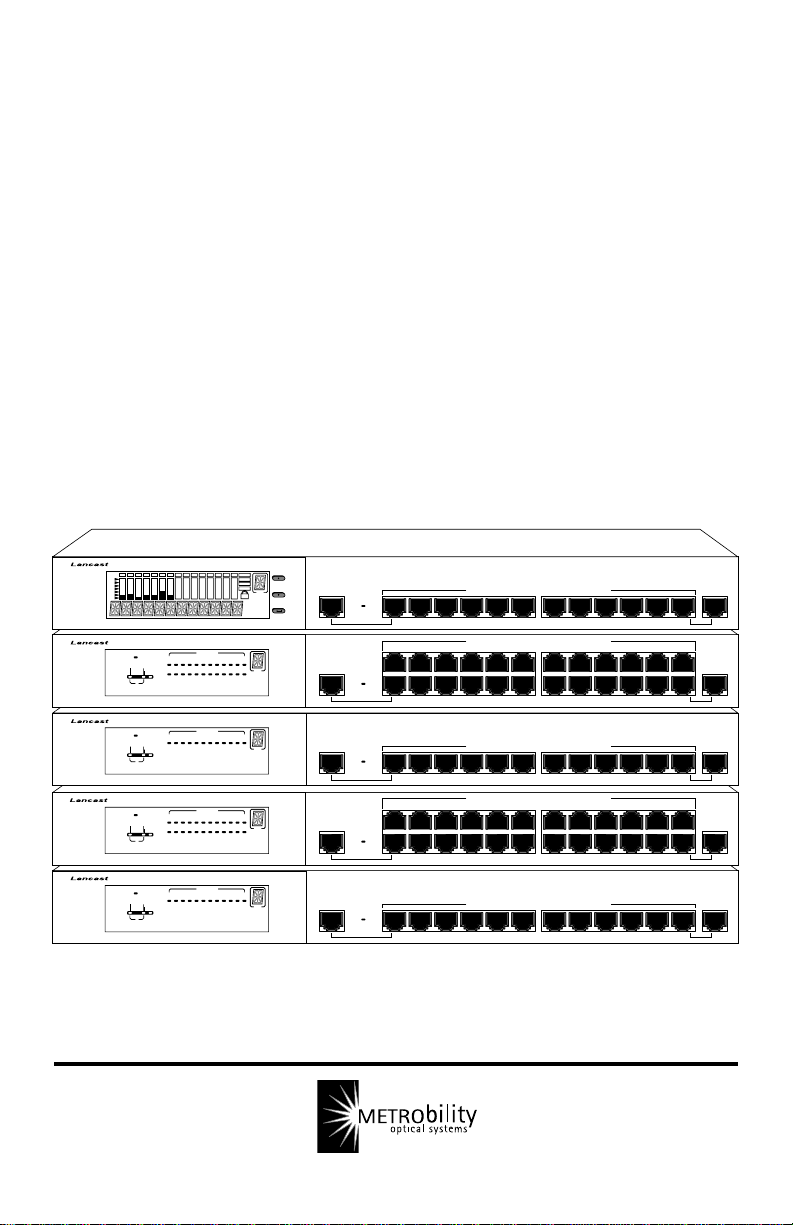
Overview of the CenturyStack 8100 Managed Hub
The CenturyStack® 8100 Series Hubs are auto sensing, dual speed,
manageable and stackable hubs. The CenturyStack 8100 Series Managed
Hubs consist of masters and managed slaves with 12 or 24 ports. The
features and functions of the CenturyStack 8100 Managed Series makes it
a powerful, cost-effective solution for large campus networks and rapid
growth companies.
All models in the CenturyStack 8100 Series Managed Hubs accept slide-in
expansion modules, adding more power and versatility , such as: bridging
10Mbps and 100Mbps segments and extending distances up to 2 kilometers.
Dual Speed CenturyStack Managed Hub 8112-01-M/S
The CenturyStack twelve port models are 8112-01-M (master) and the
8112-01-S (managed slave).
The 8112-01-M master model shown below includes a Network
Management Unit (NMU), Mini-Console, 12 dual-speed auto sensing
ports, 2 MDI-II ports and a switch module expansion slot.
®
TM
CenturyStack
8112-01-M
Dual Speed CenturyStack Hub 8112-01-M (Master with NMU)
Prev
ID
MDI-II
Next
Switch Module
Enter
Installed
1x 2x 3x 4x 5x 6x 9x8x7x 10x 11x 12x
10/100 Mbps Dual Speed Ethernet Hub
Introduction 7
MDI-II
Page 8
8112-01-S
The 8112-01-S managed slave model shown below, includes an LED
panel, 12 dual-speed auto sensing ports, 2 MDI-II ports, and a switch
module expansion slot. The 8112-01-S can be fully managed by any
master model.
®
®
CenturyStack
Collision
Forward
Power
100M
Int.
Switch
123456788101112
10M
Ext.
Switch
Link/RX
ID
MDI-II
Switch Module
Installed
1x 2x 3x 4x 5x 6x 9x8x7x 10x 11x 12x
10/100 Mbps Dual Speed Ethernet Hub
Dual Speed CenturyStack Hub 8112-01-S (Managed Slave)
Dual Speed CenturyStack Managed Hub 8124-01-M/S
The CenturyStack twenty-four port models are 8124-01-M (master) and
8124-01-S (managed slave).
The 8124-01-M master model shown below includes a Network
Management Unit (NMU), Mini-Console, 24 dual-speed auto sensing
ports, 2 MDI-II ports and a switch module expansion slot.
MDI-II
®
®
8124-01-M
CenturyStack
Prev
ID
MDI-II MDI-II
Next
Enter
13x 14x 15x 16x 17x 18x 21x20x19x 22x 23x 24x
Switch Module
Installed
1x 2x 3x 4x 5x 6x 9x8x7x 10x 11x 12x
Dual Speed CenturyStack Hub 8124-01-M (Master with NMU)
The 8124-01-S Managed Slave model shown below, includes an LED
panel, 24 dual-speed auto sensing ports, 2 MDI-II ports, and a switch
module expansion slot. The 8124-01-S can be fully managed by any
master hub model.
®
®
8124-01-S
CenturyStack
Collision
Forward
Power
100M
Switch
13 1415 16 17 18 1920 21 22 23 24
10M
123456789101112
Ext.
Switch
Int.
Link/RX
ID
MDI-II MDI-II
13x 14x 15x 16x 17x 18x 21x20x19x 22x 23x 24x
Switch Module
Installed
1x 2x 3x 4x 5x 6x 9x8x7x 10x 11x 12x
Dual Speed CenturyStack Hub 8124-01-S (Managed Slave)
8 CenturyStack® 8100 Managed Hub
10/100 Mbps Dual Speed Ethernet Hub
10/100 Mbps Dual Speed Ethernet Hub
Page 9
Key Features
The CenturyStack Dual Speed Managed Hub Series has many advanced
features:
10/100Mbps Auto Sensing Ports
All ports in the CenturyStack 8100 Series are dual speed auto sensing,
including the MDI-II ports. Hubs automatically detect the transmission
speed and set the port accordingly.
Stackability
Every model in the CenturyStack 8100 Series is compatible, and can be
configured in the same stack with up to 6 hubs, using cascade cables.
Expansion Slots
Every model in the CenturyStack 8100 Series has one slot for adding
expansion modules, see below. The lower slot accepts switch expansion
modules. See Chapter 2: Using Expansion Modules for more information.
The upper slot is for the Network Management Unit (NMU) only.
Slot for Network Management Unit (NMU) only
Stackable
Up
Down
Expansion Module Slot
NMU
Switch/
Transceiver
Expansion Slot
Manageability
The CenturyStack 8100 Series Hubs provide extensive management
capabilities including: Mini-Console Management for device level
management, Console Management using a VT-100 terminal emulator,
Web-Based Management using a Web Browser or SNMP network
management.
• Mini-Console Management
• Local Console/Remote Telnet
• Out-of-Band Management
• Web-Based Management
• SNMP Management
Introduction 9
AC LINE
100-240VAC
50-60Hz, 1.5A MAX
Page 10

RMON Probe Capability
The Remote Network Monitoring (RMON) probe is an instrument that
exists for the purpose of managing a network. The goals of the RMON
probe are described in the following sections: Offline Operation, Proactive Monitoring, Problem Detection and Reporting, Value Added Data,
and Multiple Managers. The CenturyStack 8100 Managed Series Hubs
support RMON group (1) statistics, group (2) History, group (3) Alarm,
and group (9) Event.
• Offline Operation: This allows a probe to be configured to
perform diagnostics and to collect statistics continuously,
even when communications with the management station
may not be possible or efficient.
• Proactive Monitoring: The monitor can notify the manage-
ment station of failure and can store historical statistical
information about the failure. The management station can
play this historical information back in an attempt to
perform further diagnosis into the cause of the problem.
• Problem Detection and Reporting: The monitor can be
configured to recognize conditions, most notably error
conditions, and to continuously check for them. When one
of these conditions occurs, the event may be logged, and
management stations may be notified in a number of ways.
• V alue Added Data: By highlighting those hosts on the
network that generate the most traffic or errors, the probe
can give the management station precisely the information
it needs to solve a class of problems.
• Multiple Managers: Remote monitoring can deal with
multiple management stations using its resources
concurrently.
10 CenturyStack® 8100 Managed Hub
Page 11

Redundant Link Capacity
Redundant links can be configured enabling up to 24 pairs in a
CenturyStack. For each pair of redundant links one port must be set as the
primary and active, the other as backup and isolated. If the primary port
fails, it is isolated and the backup port is set to primary and active.
Address Tracking Capability
CenturyStack provides MAC Address based tracking capability for traffic
analysis to diagnose network problems such as Intrusion. This function
records the source MAC address of each data packet received by the port
and provides the filter for data analysis. Up to 15 source MAC addresses
can be detected on each port.
Source Address Search Capability
CenturyStack provides Source Address Search Capability. This active
address tracking capability is used to watch for a given MAC address and
report on which port it was seen. This capability can be used to collect the
necessary information for mapping the topology of a network. Up to 8
MAC addresses can be searched simultaneously. You can configure
address search parameters including Source MAC address and Address
Search Status with local console management, Web-Based Management
or SNMP management.
Security Intrusion Control Capability
CenturyStack provides MAC Address based Security Intrusion Control
Capability to prevent any unauthorized nodes access to the network. You
can configure the hub to take various actions when a violation is detected.
Actions include: no action, sending a trap message or partitioning a port.
Broadcast Storm Detection and Protection Capability
CenturyStack provides Broadcast Storm Detection and Protection
Capability by periodically monitoring the broadcast counters of each port
to detect a broadcast storm. Ports detected causing a broadcast storm are
automatically partitioned, a trap is sent to the network manager, or no
action is taken, depending on the configuration.
Introduction 11
Page 12
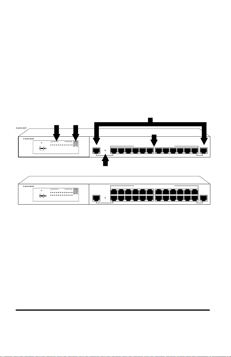
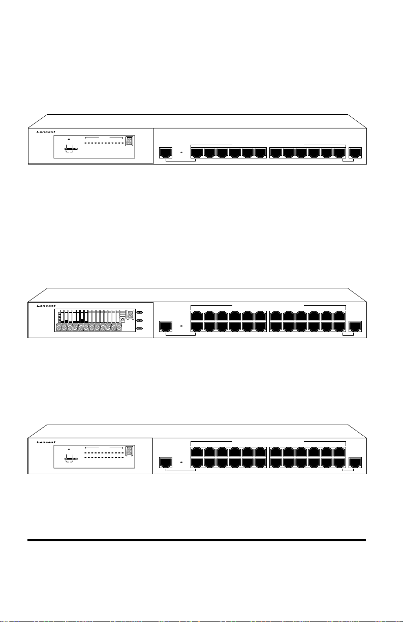
8112-01-S
Front Panel Overview: Managed Slaves
An LED panel, 12 dual-speed, auto sensing ports, switch module installed
LED, and 2 MDI-II shared ports are on the front panel of the unit.
See below.
An LED panel, 24 dual-speed, auto sensing ports, switch module installed
LED, and 2 MDI-II shared ports are on the front panel of the unit.
See below.
The Switch Module Installed LED is on if a switch module is installed in
the hub.
MDI-II Ports
LED Panel Hub ID
MDI-X Ports
10/100 Mbps Dual Speed Ethernet Hub
CenturyStack
®
®
Power
100M
Collision
Forward
Int.
Switch
123456788101112
10M
Ext.
Switch
Link/RX
ID
MDI-II
Switch Module
Installed
1x 2x 3x 4x 5x 6x 9x8x7x 10x 11x 12x
Switch Module Installed LED
MDI-II
®
®
8124-01-S
CenturyStack
Collision
Forward
Power
100M
Switch
10M
Ext.
Switch
Int.
Link/RX
13 1415 16 17 18 1920 21 22 23 24
123456789101112
ID
MDI-II MDI-II
13x 14x 15x 16x 17x 18x 21x20x19x 22x 23x 24x
Switch Module
Installed
1x 2x 3x 4x 5x 6x 9x8x7x 10x 11x 12x
Front Panel 8112-01-S (12 Ports)
Front Panel 8124-01-S (24 Ports)
12 CenturyStack® 8100 Managed Hub
10/100 Mbps Dual Speed Ethernet Hub
Page 13
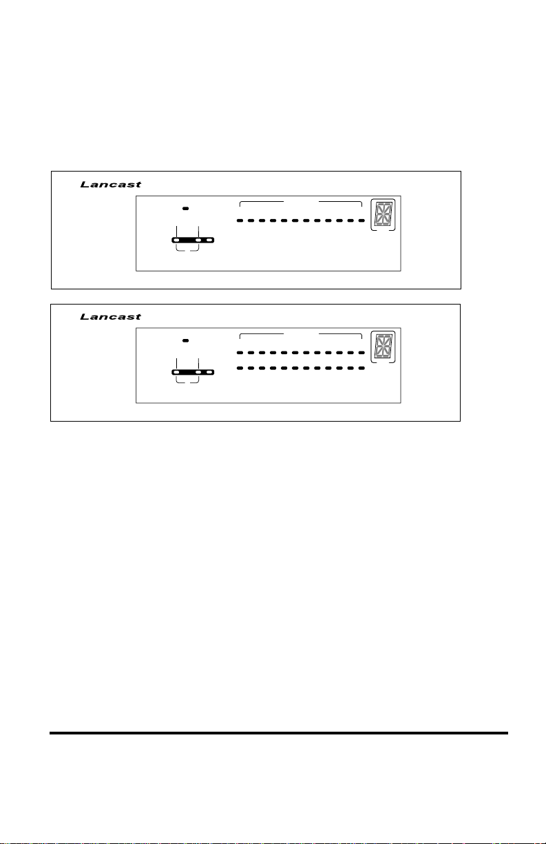
LED Indication
The hub’s LEDs indicate status information for the device, its ports for
both segments (10Mbps and 100Mbps), and switch status.
LED Indicators 12 Port
®
®
8112-01-S
8124-01-S
CenturyStack
CenturyStack
®
Power
Collision
Forward
®
Power
Collision
Forward
100M
100M
Int.
Switch
Int.
Switch
10M
10M
123456788101112
Ext.
Switch
13 14 15 16 17 18 19 20 21 22 23 24
123456789101112
Ext.
Switch
Link/RX
ID
Link/RX
ID
LED Indicators 24 Port
• Power: The Power LED is on when the power cable is
plugged into the hub and a wall socket.
• Link/Rx: The Link/Rx LED is on for each connected port
and blinks for ports receiving transmissions.
• Collision: Collision LEDs indicate collision for either
segment (10Mbps and 100Mbps). If there is collision in a
segment the LED for that segment is on.
• Forward: Packet forwarding is active via the switch module
connecting both 10Mbps and 100Mbps domains. Forward
LED indicates the packet forward status through the switch
modules. Forward for both segments (10Mbps and
100Mbps) is indicated in the table on the next page.
Introduction 13
Page 14

Forwarding LED* indicator meaning
Forward Status Int Ext Meaning
LED Switch Switch
100M On On Of f A 10Mbps transmission
100M On Off On A 10Mbps transmission
10M On On Of f A 100Mbps transmission
10M On Off On A 100Mbps transmission
100M On On On A 10Mbps transmission
10M On On On A 100 Mbps transmission
being received by
100Mbps segment
through the internal switch
being received by
100Mbps segment through
the external switch
being received by 10Mbps
segment through the
internal switch
being received by 10Mbps
segment through the
external switch
being received by 100Mbps
segment through the internal
switch and through the
external distance extender
(Modules 8103-01-X and
8103-03-X only)
being received by 10Mbps
segment through the internal
switch and through the
external distance extender
(Modules 8103-01-X and
8103-03-X only)
*NOTE: Collision LED is amber. All other LEDs are green.
14 CenturyStack® 8100 Managed Hub
Page 15
• Internal Switch (Bridge): The Internal Switch LED is
always on when the internal switch (bridge) function is
active and forwarding the data.
• External Switch (Bridge): The External Switch LED is on
when data is being forwarded from one segment to another
segment through the external switch port.
• Hub ID: Each linked hub is automatically assigned a hub
ID number and this number is indicated in the ID indicator.
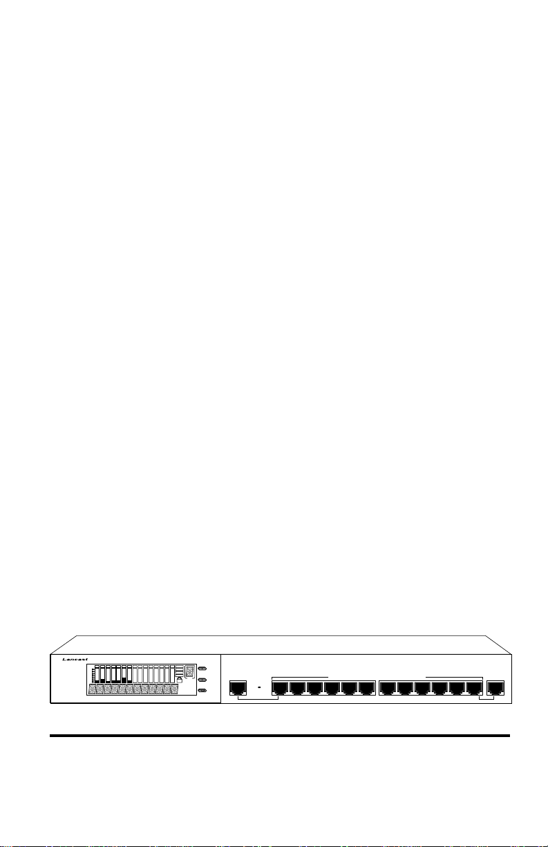
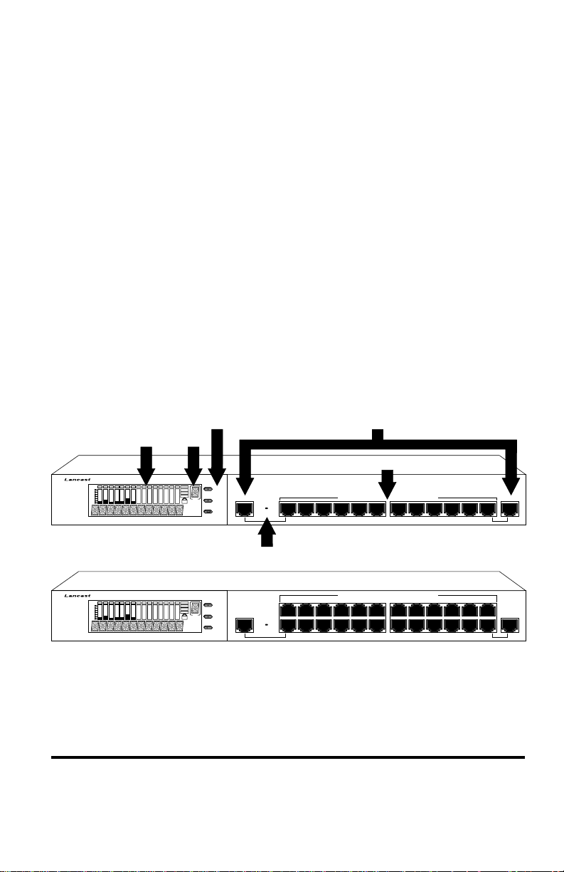
Front Panel Overview: Master Units
The front panel for model 8112-01-M supports the Mini Console, switch
module installed LED, 12-10/100 ports, and 2-MDI-II ports.
The front panel for model 8124-01-M supports the Mini Console, switch
module installed LED, 24-10/100 ports, and 2-MDI-II ports.
The switch module installed LED is on if a switch module is installed.
MDI-II PortsConsole Keys
Hub ID
ID
MDI-X Ports
Prev
MDI-II
Next
Switch Module
Enter
Installed
1x 2x 3x 4x 5x 6x 9x8x7x 10x 11x 12x
10/100 Mbps Dual Speed Ethernet Hub
8112-01-M
CenturyStack
®
®
Mini Console
MDI-II
8124-01-M
CenturyStack
Switch Module Installed LED
®
®
Prev
ID
MDI-II MDI-II
Next
Enter
13x 14x 15x 16x 17x 18x 21x20x19x 22x 23x 24x
Switch Module
Installed
1x 2x 3x 4x 5x 6x 9x8x7x 10x 11x 12x
10/100 Mbps Dual Speed Ethernet Hub
Front Panel CenturyStack 8112-01-M (12 Port)
Front Panel CenturyStack 8124-01-M (24 Port)
Introduction 15
Page 16
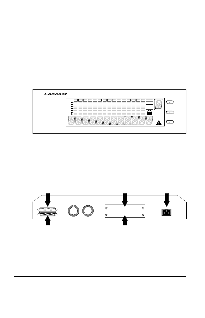
Mini Console
The Mini Console is a high definition display with console keys that
enables you to easily monitor and configure the system. The Mini
Console provides watch diagnostic functions, including port settings,
status monitoring, traffic utilization, collision, and error rate.
With the Mini Console, you can configure each device in a CenturyStack
hub and all of its ports. For more information see Chapter 3: Managing
Through the Mini Console.
®
CenturyStack
®
K%123456789101112131415G-A
80
40
20
10
5
3
1
G-B
G-C
G-D
ID
Master
WWW
SNMP
O-O-B
Prev
Next
Enter
8124-01-M
Mini Console
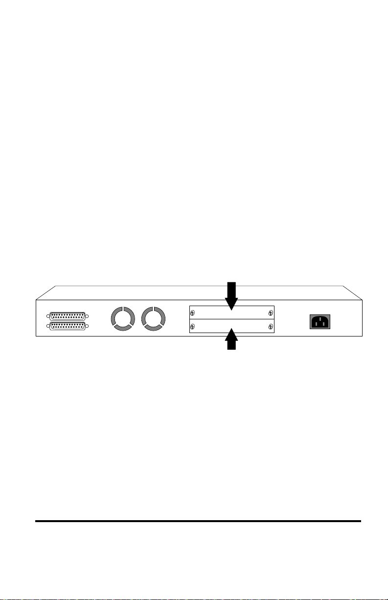
Rear Panel Overview
The rear panel of each hub in the CenturyStack 8100 Series supports
2-expansion slots, two cascade ports and an AC power socket.
The cascade ports are used for cascading hubs (stacking hubs); the Up
port of one hub must be connected to the Down port of the other hub.
Up Link
Stackable
Down Link
Up
Down
NMU Module Slot
Expansion Module Slot
16 CenturyStack® 8100 Managed Hub
AC Power Socket
NMU
Switch/
Transceiver
AC LINE
100-240VAC
50-60Hz, 1.5A MAX
Page 17

Chapter 1
Installation
Choosing a Location
The CenturyStack location should be less than 100 meters from servers,
workstations, or switches. The CenturyStack can be desk mounted or rack
mounted.
CAUTION: Category 5 UTP/STP cables are environmentally
sensitive. Make sure that the cable route is not too close to
electrical noise sources such as power lines or fluorescent lights.
Stacking
The CenturyStack Managed Series are stackable in standard 19” racks.
Up to six hubs can be stacked with cascade cables. One master and up to
five slaves can make up a stack. The master can be positioned anywhere
in the stack, so you can add to a stack without re-positioning the hubs.
Rack Mounting
Rack mounting brackets are included to mount hubs in a standard EIA
19-inch racks.
Align the mounting brackets on the sides of the unit with the slit over the
holes. Secure the screws tightly to fix the brackets to the device. Then,
place the device into the 19" rack and affix it properly. Please ensure that
the ventilation holes on the unit are not blocked.
Using Cascade Cables
You can stack the CenturyStack 8100 Series hubs using cascade cables.
The master hub can be placed anywhere in the stack. By cascading the
hub stack, each hub is automatically identified and assigned an ID number
according to its position in the stack.
Installation 17
Page 18
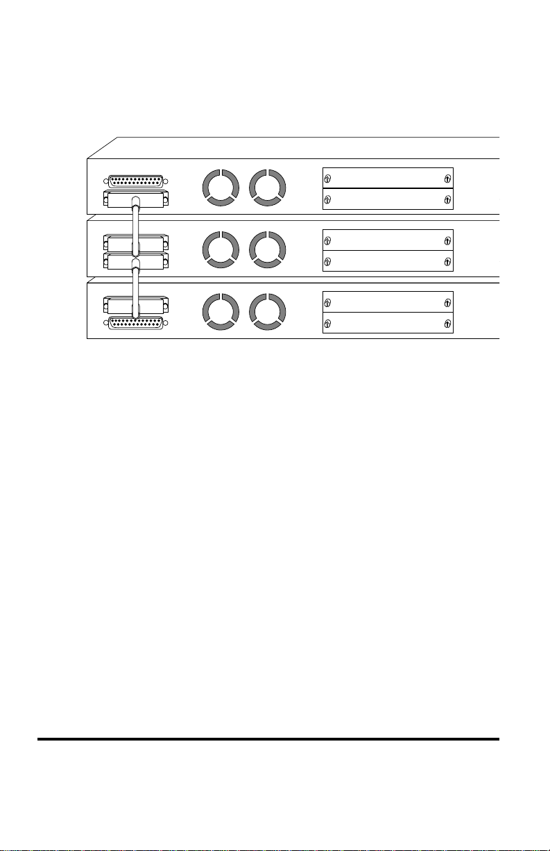
Cascading hubs with cascade cables to make a stack is as simple as
connecting the Up port of one hub to the Down port of another hub as
illustrated below.
Stackable
Stackable
Stackable
Up
Down
Up
Down
Up
Down
NMU
Switch/
Transceiver
NMU
Switch/
Transceiver
NMU
Switch/
Transceiver
Cascade Ports
NOTE: T o connect the cascade cable, the Up port on one hub connects to
the Down port of another hub.
Constructing a Management Hub Stack
A stack can be constructed with up to six hubs in total. One master hub
and up to five slave hubs can exist in one stack.
Position within the Stack
The master hub can be positioned anywhere in a stack and automatically
assigns the ID of each hub according to its position in the stack.
Master Hub Role
The master is used to manage and configure other hubs in the stack and
supplies the stack with additional ports (12/24) and an additional expansion module slot. The master hub can also be used as a stand-alone
intelligent hub. Managing the hubs can be accomplished with the master
hub’s versatile management capabilities, such as:
• Mini Console Management
Refer to Chapter 3: Managing Through the Mini Console
18 CenturyStack 8100 Managed Hub
Page 19

• Console Management
Refer to Chapter 4: Console Management
• Web-Based Management
Refer to the CenturyStack Network Management Guide
• SNMP Management
Refer to the CenturyStack Network Management Guide
Slave Hub Role
Slave hubs supply the stack with additional ports (12/24) and an additional expansion module slot. Slave hubs can be positioned above or
below the master hub. The 8112-01-S and 8124-01-S can also act as stand
alone unmanaged hubs.
Hub ID
The master hub and slave hubs can be positioned anywhere in the stack
and each hub’s ID is automatically assigned based on its position (in the
stack).
Segmenting Hubs
CenturyStack hubs can isolate one or both segments (10 Mbps and 100
Mbps segments) from the other hubs in a stack. When a segment is
isolated it does not repeat to the other segments in the hub or to other
segments in the stack.
Connecting Devices
The dual speed CenturyStack can connect to 10Mbps, 100Mbps, or
10/100Mbps devices due to its auto sensing capability. CenturyStack will
auto sense the connected port speed and set its port to match the speed of
the connected port.
Cables
CenturyStack ports accept Cat 3, 4 and 5 cables with RJ-45 connectors
for 10Mbps connections and Cat 5 cables with RJ-45 connectors for
100Mbps connections. The maximum length of cables, between hub and
workstations is 100 meters. The maximum length of cables, between hub
and hub is 5 meters for 100Mbps connections and 100 meters for
Installation 19
Page 20
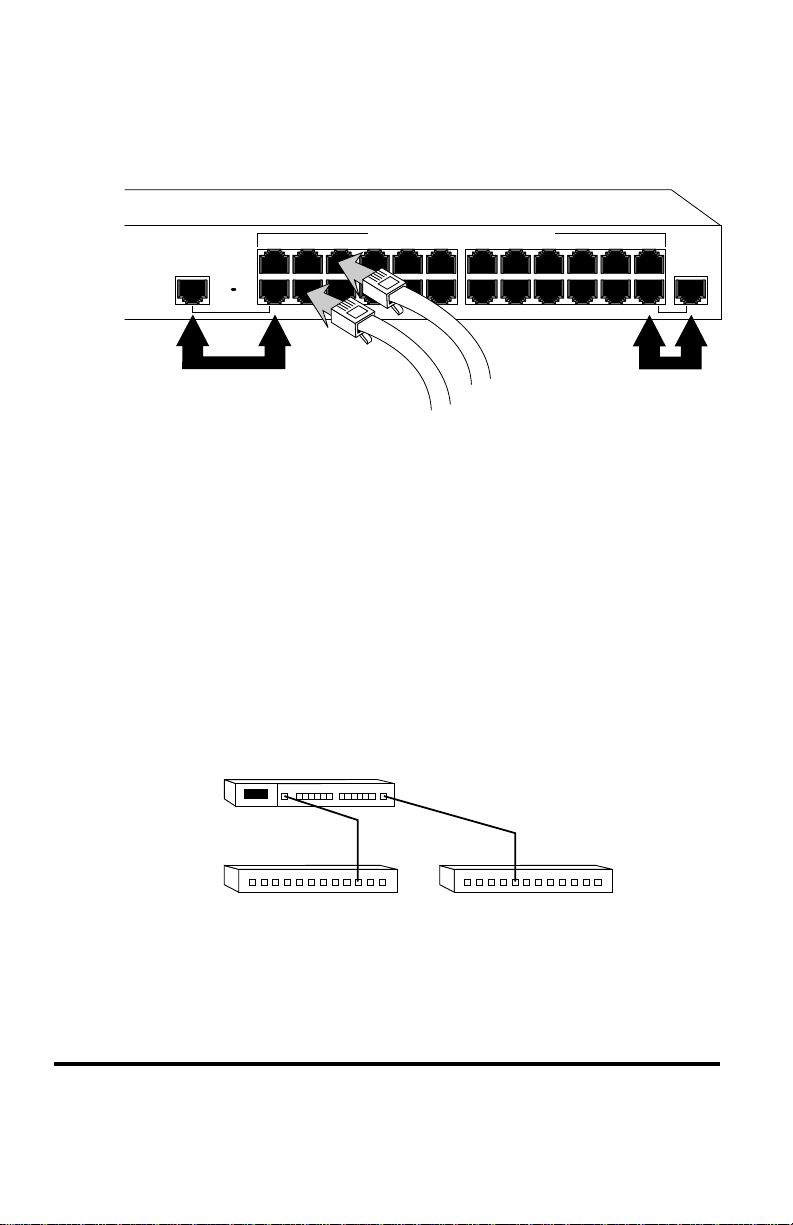
10Mbps connections. All ports are hot pluggable. It is recommended you
label each cable to identify the device or port at each end.
13x 14x 15x 16x 17x 18x 21x20x19x 22x 23x 24x
MDI-II MDI-II
Switch Module
Installed
1x 2x 3x 4x 5x 6x 9x8x7x 10x 11x 12x
Shared Ports
10/100 Mbps Dual Speed Ethernet Hub
Shared Ports
Connecting Devices
Connecting Workstations
Install either a 10BASE-T or a 100BASE-TX Fast Ethernet Network
Interface Card into each workstation if not already installed. Using a
UTP/STP cable, connect the Ethernet card (in the workstation) to a
CenturyStack port.
Connecting Ethernet Hubs or Devices
Connect 10Mbps devices using UTP/STP Cat 3, 4 or 5 cables with RJ-45
connectors, enabling sending/receiving to or from other 10Mbps devices.
By default, each port is set in auto sensing mode. CenturyStack can detect
a 10BASE-T device and transmit/receive information to/from it.
CenturyStack 81XX
10Mbps
Connecting Ethernet Hubs
20 CenturyStack 8100 Managed Hub
Page 21
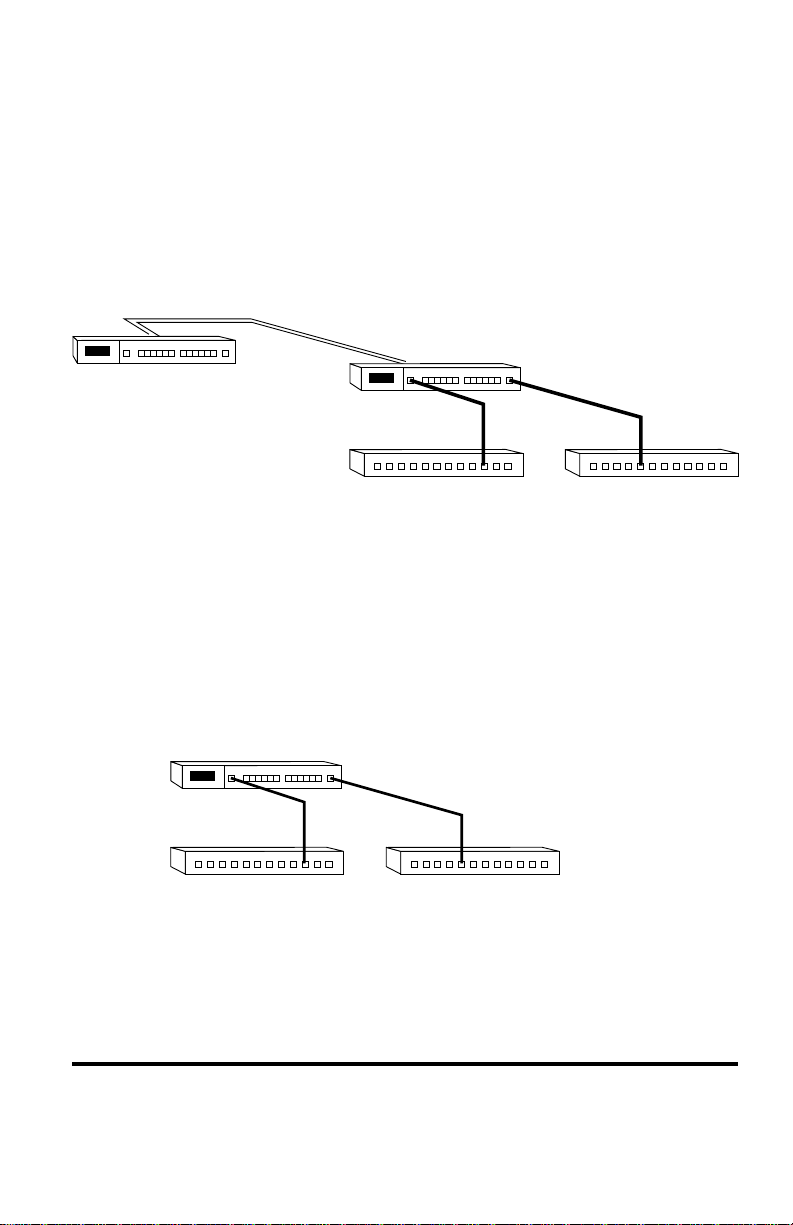
Connecting Fast Ethernet Switching Hubs
Connect 100Mbps devices using UTP/STP Cat 5 cables with RJ-45
connectors, maximum length 5 meters, enabling sending/receiving to
other fast Ethernet switching hubs. By default, each port is set to auto
sensing mode. CenturyStack can detect a connected 100BASE-TX device
and transmit/receive information to/from it. The distance between
switching hubs can be extended up to 2km by connecting two hubs
through expansion modules using fiber cable.
up to 2km Fiber
CenturyStack 81XX
100Mbps
Connecting Fast Ethernet Hubs
Connecting the Other Dual Speed Hubs
Other dual speed hubs can be connected to the ports of the CenturyStack
Hubs. Each port can auto sense the connected port speed and set its speed
to match the connected port. The maximum distance between devices is 5
meters using Cat 5 UTP/STP cable. To increase the distance between dual
speed hubs you must use fiber cable and connect using an expansion
switch module. For more information about expansion switch modules,
refer to Chapter 2: Using Expansion Modules.
CenturyStack 81XX
10/100Mbps Hub 10/100Mbps Hub
Connecting Other Dual Speed Hubs to a CenturyStack Hub
Installation 21
Page 22

22 CenturyStack 8100 Managed Hub
Page 23

Chapter 2
Using Expansion Modules
Expansion Module Overview
Expansion modules provide additional functions such as internal bridging
of 10Mbps and 100Mbps segments and extended distances between
devices. The available modules are:
• Module 8102-01-X: 2 port Bridge or 10/100BASE-TX
Switch Module
• Module 8102-03-X: 2 port Bridge or 100BASE-FX
Fiber Distance Extender Switch Module
• Module 8103-01-X: 3 port Bridge and 10/100BASE-TX
Switch Module
• Module 8103-03-X: 2 port Bridge and 100BASE-FX
Fiber Distance Extender Switch Module
With CenturyStack, the software setting for Bridging Module Admin State
(external distance extender function and internal function) is disabled by
default. The Admin State of a bridge module must be configured using
Console or Web-Based Management after installation.
Internal Bridge Function
The Internal Bridge Function is used for bridging 10Mbps and 100Mbps
segments in a hub or in a stack. Only one internal switch can be enabled
in a CenturyStack, more than one will cause network looping.
IMPORTANT: There can only be one internal switch enabled in a
CenturyStack, however multiple external bridges are allowed. Therefore,
if more than one module exists in a CenturyStack, ensure that only one
module has its internal bridge enabled.
External Bridge Function
The external bridge function is used to extend the distance between
100Mbps hubs or stacks from the normal limitation of five meters to one
hundred meters with TX modules using RJ 45 cable. With FX modules
using fiber cable, you can expand the distance between hubs or stacks up
to 2km.
Using Expansion Modules 23
Page 24

Backpressure (flow control)
When packets are passed from 100Mbps segments to 10Mbps segments
the flow is restricted due to the lesser capacity of the 10Mbps segment
causing backpressure and resulting in dropped packets. With flow control
or backpressure enabled, packets are made to wait until the flow is
unrestricted before being sent, reducing the number of dropped packets.
Installing a Bridge Module
Power down CenturyStack before installing a bridge module. Bridge
modules have both hardware and software configuration settings. The
hardware configurations must be made before you physically install the
module and the software configurations must be made using a master hub,
after the module is installed and before the bridging functions take effect.
Please read this section carefully before installing modules.
IMPORTANT:
• These modules are not hot swappable. You must remove
power from the hub before installing or replacing a
bridge module.
• You should enable the internal bridge on only one bridge
module when you have multiple bridge modules installed
in a CenturyStack. This prevents a network loop
condition.
• Three bridge modules are shipped with the Internal
Bridge function enabled (8102-01-X, 8103-01-X and
8103-03-X), only the 8102-03-X is shipped with the
Internal Bridge function disabled. All models ship with
the backpressure function disabled.
To install these modules, perform the following steps. Use static sensitive
precautions.
1. Set the bridge function and backpressure function by moving
the appropriate jumpers. See the following sections for the
bridge module model that you are installing and set the
jumpers accordingly.
24 CenturyStack 8100 Managed Hub
Page 25
2. Remove the power from the hub by disconnecting the power
cable from the AC outlet.
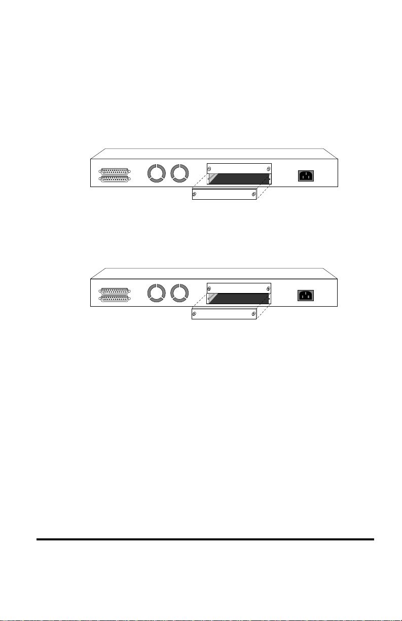
3. Remove the installed bridge module or blank cover of the
expansion module slot (not the NMU slot, only the bottom
slot is available) by turning the two knobs on the front
counterclockwise as shown below.
Stackable
Up
Down
NMU
Switch/
Transceiver
AC LINE
100-240VAC
50-60Hz, 1.5A MAX
Removing the Blank Module Panel
4. Insert the new module, ensuring that the edges slide through
the guides, as shown below.
Stackable
Up
Down
Insert the Module
NMU
Switch/
Transceiver
AC LINE
100-240VAC
50-60Hz, 1.5A MAX
5. Turn the two knobs on the new bridge module until they are
securely attached to the hub.
6. Connect the appropriate communication cable to the new
module.
7. For stand alone slave models the installation is complete,
just connect AC power.
8. If your adding this hub to an existing stack, connect the hub
to the stack. Refer to Chapter 1: Using Cascade Cables.
9. Reconnect the AC power cord to the wall outlet.
Using Expansion Modules 25
Page 26

10.For a hub stack with a master present, you must configure
the software for the installed bridge module to enable the
internal bridge function because the software default setting
is disabled. The default software setting will not allow the
internal bridge function to enable. The software must be
configured using a master hub.
11.Start a Console or Web-Based Management session and set
the software configuration for the new module. For
information on starting a console session, refer to
Chapter 4: Console Management. For information on
Bridge Module configuration, refer to Chapter 4: Console
Management: Controlling Devices.
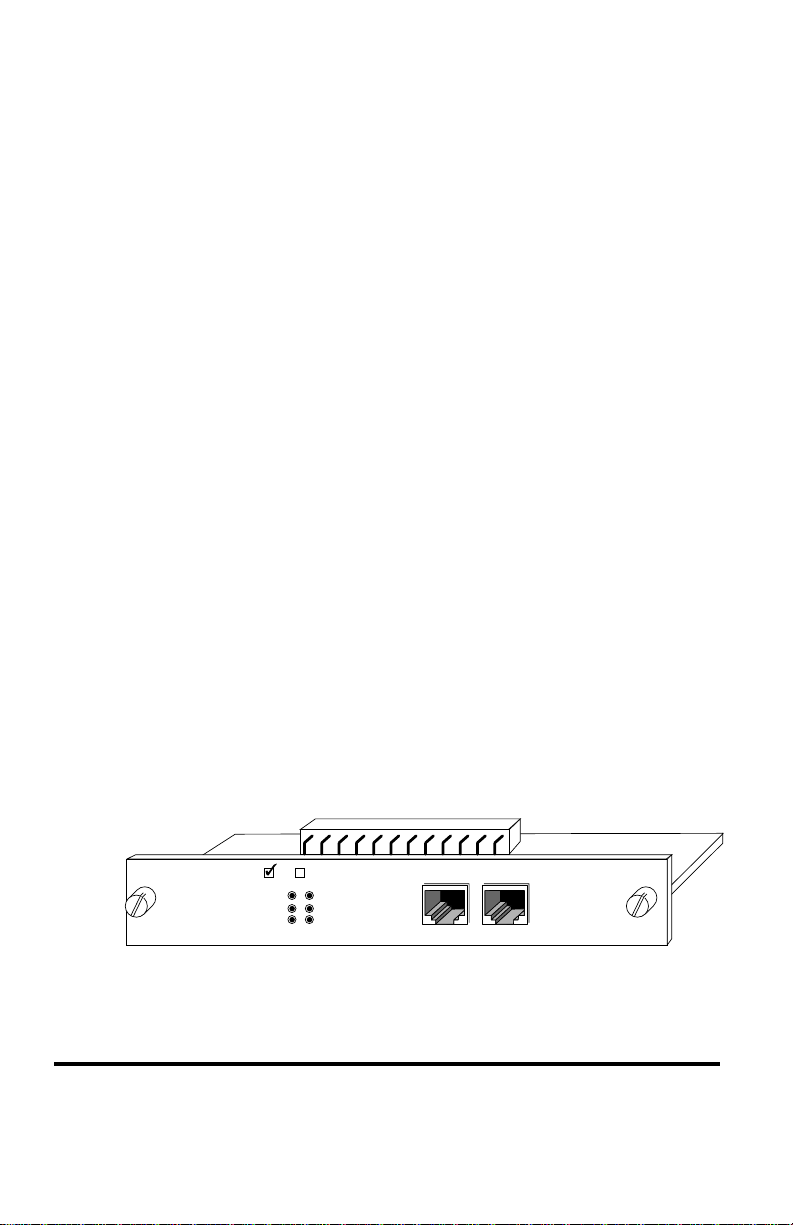
TX Module LED Indicators
The LEDs on each module indicate port activity. All LEDs are green.
• Link: On, indicates a link is up.
• TX: On, indicates a transmission in progress.
• RX: On, indicates receiving data.
• 100M: On, indicates the 100 Mbps segment is linked.
Off, indicates the 10 Mbps segment is linked
when TX or RX LED is also on. (NOTE: if there
is no cable connected to the module, the LED is
on by default)
• FDX: On, indicates the port is set to full duplex.
Off, indicates the port is set to half duplex.
• Collision:On, indicates collision occurring.
2
Switch Module
LINK
Link up
TX
RX
Transmit
Receive
TX Module LEDs
26 CenturyStack 8100 Managed Hub
3 Ports
100M
FDX
COL
100Mbps Segment
Full Duplex
Collision
Page 27

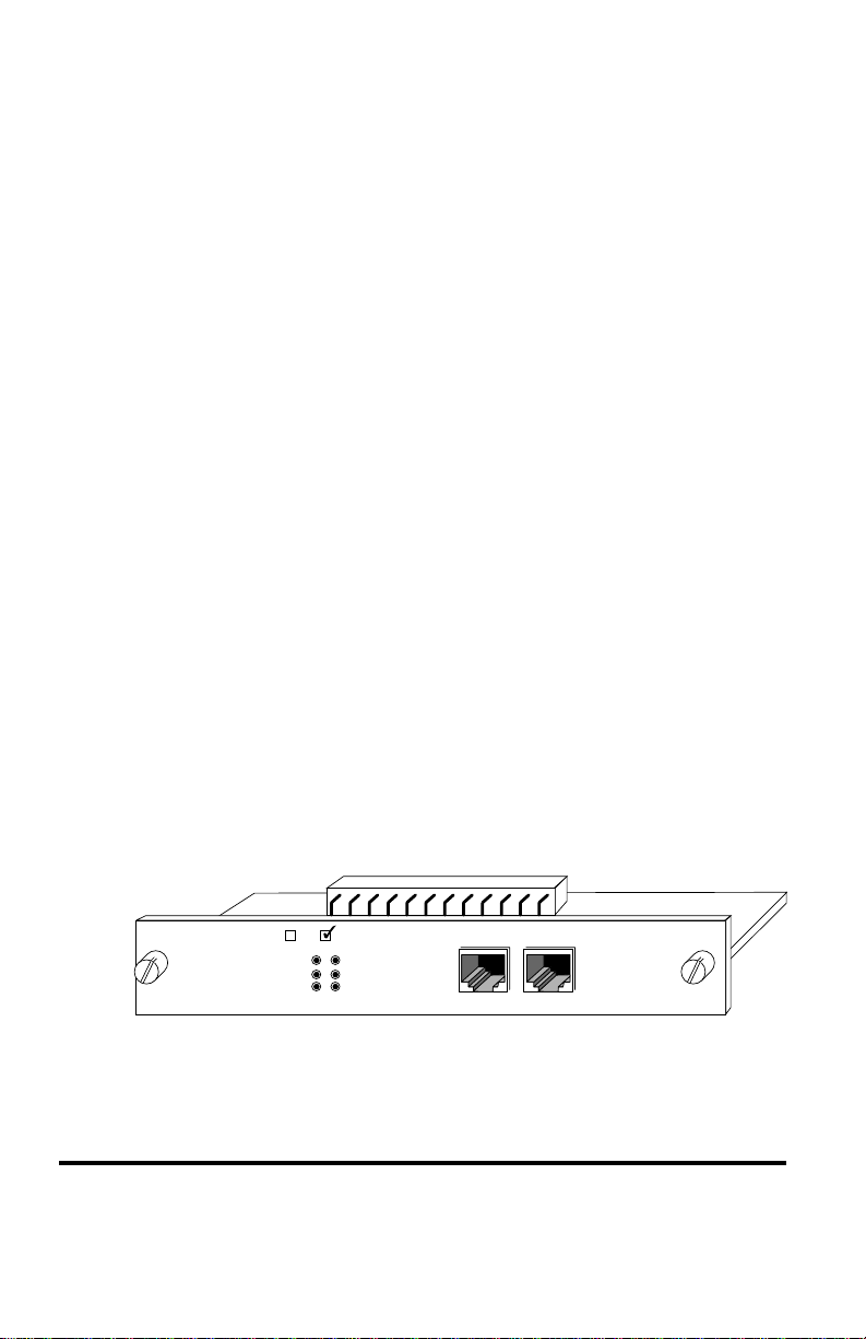
FX Module LED Indicators
The LEDs on each module indicate port activity. All LEDs are green.
• Link: On, indicates a link is up.
• TX: On, indicates a transmission in progress.
• RX: On, indicates receiving data.
• FDX: On, indicates the port is set to full duplex.
Off, indicates the port is set to half duplex.
• Collision:On, indicates collision occurring.
3 Ports
2
Switch Module
LINK
Link up
Transmit
Receive
TX
RX
FX Module LEDs
FDX
COL
Full Duplex
Collision
NOTE: Fiber Modules support 100Mbps only.
Using Expansion Modules 27
Page 28
Module 8102-01-X
Module 8102-01-X is either an internal bridge for bridging the internal
10Mbps and 100Mbps segments or an external 10/100BASE-TX distance
extender with MDI-X and MDI-II interfaces using an RJ-45 cable. Only
one of these functions can be enabled at one time. The internal or external
bridge must be enabled or disabled with on board jumpers before installation. Module flow-control (backpressure) can be enabled or disabled by
setting the on board jumpers before installation. The default settings are
as follows:
• Bridge Function setting: Internal (Default)
• Backpressure setting: Disabled (Default)
Module 8102-01-X Bridge Jumpers
The default jumper setting of the 8102-01-X module is internal bridge
enabled. To disable the internal bridge and enable the external bridge,
change the jumpers (JP1~JP16) from 1&2 to 2&3.
Jumpers JP1~JP16
• 1&2 connected = internal bridge is enabled (Default)
• 2&3 connected = external bridge is enabled
Module 8102-01-X Backpressure Jumpers
The default jumper setting for backpressure is disabled. To enable the
backpressure function, change JP18 jumper to 2&3.
Jumper JP18
• 1&2 =disabled (Default)
• 2&3 = enabled
2
3 Ports
Switch Module
LINK
100M
TX
FDX
COL
RX
MDI-X
28 CenturyStack 8100 Managed Hub
100BASE-TX
MDI-II
Page 29
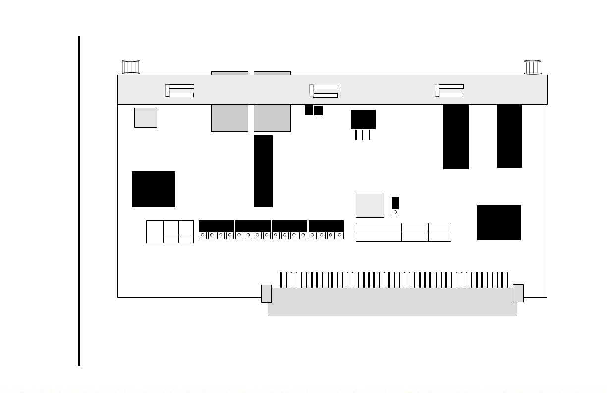
Jumpers: Module 8102-01-X
Using Expansion Modules 29
JP1
I
JP16
INT
SW
1-2
EXT
SW
2-3
JP1
JP2
JP3
JP4
JP5
JP6
JP7
JP8
JP9
JP10
JP11
JP12
JP13
JP14
JP15
1
Backpressure
2
3
JP16
JP18
1
2
3
JP18
Disable Enable
1-2 2-3
Page 30
Module 8103-01-X
Module 8103-01-X is a 3-port bridge module with a two port internal
bridge for bridging 10Mbps and 100Mbps segments and an external
10/100BASE-TX distance extender with MDI-X and MDI-II interfaces
using an RJ-45 cable. Both of these functions can be enabled at one time,
in fact, the distance extender is always enabled. The internal or external
bridge must be enabled or disabled with on board jumpers before installation. Module flow-control (backpressure) can be enabled or disabled by
setting the on board jumpers before installation. The default settings are
as follows:
• Bridge Function setting: Internal and External enabled
(Default)
• Backpressure setting: Disabled (Default)
Module 8103-01-X Bridge Jumpers
The default jumper setting of the internal bridge of Module 8103-01-X is
enabled. The external distance extender is always enabled. To disable the
internal bridge, change the jumpers (JP2, J4 ~ JP6) from 2&3 to 1&2.
Jumpers JP2, JP4 ~ JP6
• 1&2 connected = internal bridge is disabled
• 2&3 connected = internal bridge is enabled (Default)
Module 8103-01-X Backpressure Jumpers
The default jumper setting for backpressure is disabled. To enable the
backpressure function, change JP1 and JP7 jumpers to 2&3.
Jumpers JP1, JP7
• 1&2 = disabled (Default)
• 2&3 = enabled
2
3 Ports
Switch Module
LINK
100M
TX
FDX
COL
RX
MDI-X
30 CenturyStack 8100 Managed Hub
100BASE-TX
MDI-II
Page 31

Jumpers: Module 8103-01-X
Using Expansion Modules 31
JP1,
JP2
Backpressure
2-3JP7
Int Sw Enable
2-3JP4 – JP6
JP1
3
2
1
Backpressure dis
1-2
Int Sw Disable
1-2
3
2
1
JP7
JP6
JP5
JP4
JP2
Page 32

Module 8102-03-X
Module 8102-03-X provides a two port internal bridge for bridging
10Mbps and 100Mbps segments or 100BASE-FX distance extender with
SC type connectors for fiber cable. The internal bridge must be enabled
with on board jumpers before installation. The external distance extender is
enabled by default. Module flow-control (backpressure) can be enabled or
disabled by setting the on board jumpers before installation.
The default settings are as follows:
• Bridge Function setting: Internal disabled (Default)
• Backpressure setting: Disabled (Default)
Module 8102-03-X Bridge Jumpers
The default jumper setting of the Module 8102-03-X is internal bridge
disabled. To enable the internal bridge and disable the external bridge
change the jumpers (JP2~JP17) from 2&3 to 1&2.
Jumpers JP2~JP17
• 1&2 connected = internal bridge is enabled
• 2&3 connected = external bridge is enabled (Default)
8102-03-X Duplex Jumper
When the Module 8102-03-X internal bridge is enabled, the duplex jumper
should be set to Half Duplex.
Jumper JP1
• 1&2 = half-dulex enabled
• 2&3 = full-duplex enabled
Module 8102-03-X Backpressure Jumpers
The default jumper setting for backpressure is disabled. To enable the
backpressure function, change JP19 jumper to 2&3.
Jumper JP19
• 1&2 = disabled (Default)
• 2&3 = enabled
3 Ports
2
Switch Module
LINK
TX
FDX
COL
RX
32 CenturyStack 8100 Managed Hub
Page 33

JP1
HDX
1-2
FDX
2-3
JP1
Jumpers: Module 8102-03-X
3
2
1
Using Expansion Modules 33
JP2
JP3
JP4
JP5
JP6
JP7
JP8
JP9
JP10
JP11
JP2
JP17
JP12
I
JP13
INT
SW
1-2
JP14
JP15
EXT
SW
2-3
JP16
3
Backpressure
2
1
JP17
JP19
3
2
1
JP19
Disable Enable
1-2 2-3
Page 34

Module 8103-03-X
Module 8103-03-X provides a two port internal bridge for bridging
10Mbps and 100Mbps segments and 100BASE-FX distance extender with
SC type connectors and fiber cable. The internal bridge must be enabled or
disabled with on board jumpers before installation. The external distance
extender is always enabled. Module flow-control (backpressure) can be
enabled or disabled by setting the on board jumpers before installation. The
default settings are as follows:
• Bridge Function setting: Internal enabled (Default)
• Backpressure setting: Disabled (Default)
Module 8103-03-X Bridge Jumpers
The default jumper setting of the Module 8103-03-X is internal bridge
disabled. The external distance extender is always enabled. To enable the
internal bridge, change the jumpers (JP3 & JP5~JP7) from 1&2 to 2&3.
Jumper JP1—Duplex Jumper (JP1)
• 1&2 = half duplex
• 2&3 = full duplex
Jumpers JP3 & JP5~JP7
• 1&2 connected = internal bridge is disabled (Default)
• 2&3 connected = internal bridge is enabled
Module 8103-03-X Backpressure Jumpers
The default jumper setting for backpressure is disabled. To enable the
backpressure function for the external port and internal 100Mbps segment,
change JP2 jumper to 2&3. To enable the backpressure function for the
internal bridge change JP8 jumper to 2&3.
Jumpers JP2, JP8
• 1&2 = disabled (Default)
• 2&3 = enabled
3 Ports
2
Switch Module
LINK
TX
FDX
COL
RX
NOTE: JP2 is used to control the distance extender port and internal
100Mbps-segment backpressure function. JP8 is used to control internal
bridge backpressure function.
34 CenturyStack 8100 Managed Hub
Page 35

JP1
3
2
HDX
FDX
1
JP1
1-2
2-3
Jumpers: Module 8103-03-X
Using Expansion Modules 35
JP3
&
JP5-7
JP2, JP8
2-3
1-2
Int Sw Enable
2-3
JP2
1
2
3
Backpressure
Backpressure dis
Int Sw Disable
1-2
3
2
1
JP8
JP7
JP6
JP5
JP3
Page 36

36 CenturyStack 8100 Managed Hub
Page 37

Chapter 3
Managing Through the Mini Console
Mini Console Overview
The Mini Console is a high definition display panel that provides brilliant
text and graphics. It displays information about the system, port status or
other information depending on the menu selected. Extensive configuration settings can be viewed and configured with the Mini Console. The
Mini Console is only available for the CenturyStack master units.
Features
• High definition display panel (text and graphics)
• Message Zone
• Gauge Bars
• % Indicators
• Port Indicators
• Port Frame Indicators
• Console Keys
• Hub ID
• Group Indicators
• Symbols (Lock, Caution, WWW, SNMP & OOB)
Mini Console Display Panel
Console Keys
Port Number Indicator Group Indicators
®
®
CenturyStack
8124-01-M
K%123456789101112131415G-A
80
40
20
10
5
3
1
Port Frame Hub ID
G-B
G-C
G-D
ID
Master
WWW
SNMP
O-O-B
Lock Symbol
Gauge BarsMessage Zone Caution Symbol
Prev
Next
Enter
Management
Mini Console
Managing Through the Mini Console 37
Page 38

VFD Display
The Vacuum Florescent Display (VFD) shows the following port and
system information:
%: The relative percentage of utilization or collision.
Port Number Indicators: Indicates the number of a port, and by
brightness, indicates status information. See the next table.
Port Indicator Frame: Indicates which ports are disabled and
partitioned.
Message Zone: The Message Zone displays the menu items of
the menu tree, port information and system information
including self-diagnostic tests and error messages.
Gauge Bars: Displays information such as utilization, port
status, and serves as an indicator for groups or ports.
Lock Icon: Indicates that the control panel configuration is locked.
G-A: Port group indicator displays status of ports 1 to 12.
G-B: Ports 13 to 24.
Master: Indicates this hub is a master hub.
WWW: Indicates the Web-Based Management feature is enabled.
SNMP: Indicates the hub is SNMP manageable.
OOB: Indicates that out-of-band is enabled.
Observing Basic Port Information
The basic port information, such as link up, link down, receive activity,
enabled and disabled, and auto partition can be easily viewed through the
gauge bar, Message Zone and Port Indicators located in the first row of the
Mini Console. The gauge bars below each linked port ascend and descend
in relation to the amount of traffic through the ports.
38 CenturyStack 8100 Managed Hub
Page 39

Port Indicator Definition
The port number indicators define the port status and activity by the way
they are illuminated, such as ON, OFF, flashing and with a frame around
the numbers.
The following table summarizes the definition of the port indicators.
Port Indicator Definitions
Port No. (Green) Frame (Amber) Indicates
Normal OFF Port is available but link is down.
Bright OFF Port is available and link is up.
Bright ON The Link is up and the administrator has
Normal ON The Link is down and the administrator
Flashing OFF Link is up and receiving data.
Normal BLINKING The port is partitioned by the machine
disabled the port.
has disabled the port.
itself due to errors.
Console Keys
The Console Keys are used to cycle through the menu tree, to make
selections and settings. The Prev Key and the Next Key cycle one
position in the same level, and the Enter Key makes a selection. To move
up the menu tree toward the root, select BACK or MAIN MENU in the
menu tree structure.
BACK: Selecting BACK moves back up one level in the
menu tree.
MAIN MENU: Selecting MAIN MENU moves directly to the
main level in the menu tree.
Managing Through the Mini Console 39
Page 40

The following summarizes the Console Key functions.
Prev: Cycles back through the current menu level.
Next: Cycles forward through the current menu level.
Enter: Selects the displayed menu item or when pressed and
held changes a setting. Holding down the Enter key changes the
default setting and places an “*” before the item indicating it is
the current default.
Menu Tree
The menu tree consists of these seven main level menus:
• Utilization
• Group Select
• Statistics
• Port Status
• Port Configuration
• Unit Configuration
• System Information
The Main Menu items and their sub menus are outlined below.
UTILIZATION Press “ENTER” to toggle port menus 1-12 or 13-24
GROUP SELECT GROUP 1~GROUP N
STATISTICS PORT 1~PORT N READABLE FRM
READABLE OCT
FCS ERRORS
ALIGN ERRORS
FRM TOO LONG
SHORT EVENTS
RUNTS
COLLISIONS
LATE EVENTS
VERY LONG EN
RATE MISMTCH
AUTO PART
TOTAL ERRORS
40 CenturyStack 8100 Managed Hub
Page 41

PORT STATUS ALL PORTS 10M PORTS
100M PORTS
LINK UP
LINK DOWN
POLAR NORMAL
POLAR REVERS
NO AUTO PARTS
AUTO PART
ENABLE
DISABLE
PORT 1~PORT N Press “ENTER” to show
the status applied to the
port
PORT CONFIG SYS LOCKED **** PSW
ALL PORT ENABLED
PORT 1~PORT N DISABLED
AUTO-NEGO
10BASE-T
100BASE-X
UNIT CONFIG CONSOLE LOCK LOCK
NETWORK CONFIG IP ADDRESS
SUBNET MASK
DEF GATEWAY
SET PASSWORD
SYS RESTART CONTINUE
CANCEL
SYS DEFAULT CONTINUE
CANCEL
EIA232 CONFG BAUD RATE 2400
4800
9600
19200
BACK
SYSTEM INFO HW VER HW version displays
SW VER SW version displays
IP ADDRESS IP Address displays
SUBNET MASK Subnet Mask displays
DEFAULT GATEWAY Default Gateway displays
Managing Through the Mini Console 41
Page 42

Observing Network Traffic
You can observe the network traffic in the Mini Console with the Utilization menu. Seven columns of gauge bars, which shift continuously from
left to right as time elapses, represent the utilization rate of each segment.
The gauge bar columns on the left are for the 10Mbps segment and the
gauge bars on the right are for the 100Mbps segment. Each column of
gauge bars is a historical view of the total utilization in the 10Mbps
segment and the total utilization in the 100Mbps segment at the time the
statistics were taken by the hub. The total utilization history, represented
by the seven columns in each segment is over a three-second time frame.
“UTILIZATION” and “10M 100M” display in the Message Zone
interchangeably at intervals of several seconds as shown below.
K%123456789101112131415G-A
80
40
20
10
5
3
1
Utilization per Port
G-B
G-C
G-D
ID
Master
WWW
SNMP
O-O-B
10Mbps Segment
Utilization
K%123456789101112131415G-A
80
40
20
10
5
3
1
Utilization per Segment
42 CenturyStack 8100 Managed Hub
100Mbps Segment
Utilization
G-B
G-C
G-D
ID
Master
WWW
SNMP
O-O-B
Page 43

Selecting a Group
You can select a group to monitor and configure when there are managed
hubs cascaded to the master hub. “Group” refers to a hub in the stack, the
range is 1~6 when the maximum number of hubs exist in the stack. You
can manage each hub using the Mini Console. To select a group:
1. From the main menu press <Next> until
“GROUP SELECT” displays in the Message Zone.
2. Press <Enter>. Several bars under the Port number indicate
the current group, as shown below.
K%123456789101112131415G-A
80
40
20
10
5
3
1
G-B
G-C
G-D
ID
Master
WWW
SNMP
O-O-B
Group Select
3. Press <Next> until the group number you wish to monitor
displays in the Message Zone as shown below.
K%123456789101112131415G-A
80
40
20
10
5
3
1
G-B
G-C
G-D
ID
Master
WWW
SNMP
O-O-B
Group 2
K%123456789101112131415G-A
80
40
20
10
5
3
1
G-B
G-C
G-D
Group 3
Managing Through the Mini Console 43
ID
Master
WWW
SNMP
O-O-B
Page 44

Monitoring Port Statistics
You can monitor statistics of individual ports or all ports simultaneously
using the Statistics Menu. The table, “Port Statistics Counters” lists the
available counters that can be monitored.
Port Statistic Counters
Counter Type Displayed
READABLE FRAMES The total number of frames received on the hub port.
READABLE OCTETS The total number of octets of data received on
FCS ERRORS The total number of packets received by the port
ALIGN ERRORS The total number of packets received that have bad
FRM TOO LONG The total number of packets received that were
SHORT EVENTS The total number of packets received that were
RUNTS The total number of packets received that were less
COLLISIONS Total collisions.
LATE EVENTS Total events received by the port where the activity
VERY LONG EVENTS Total events received by the port where the activity
the hub port.
that had bad Frame Check Sequence.
FCS with a non-integral number of octets.
longer than 1518 octets (including FCS octets
but excluding framing bits) and were otherwise
well formed.
less than 64 octets (including FCS octets but
excluding framing bits) and were otherwise well
formed.
than 64 octets due to collisions or activity duration
was greater than the ShortEventMaxTime event
and less than the ValidPacketMinTime event.
duration is greater than the LateEventThreshold.
duration is greater than the MAU Jabber Lockup
Protection timer TW3.
RATE MISMATCH Total frames received by the port with no collisions
and the activity duration greater than the
ValidPacketMinTime event and also frequency
(data rate) is mismatched from the local frames
mismatch frequency.
44 CenturyStack 8100 Managed Hub
Page 45

AUTO PART Total number of times the port was auto-partitioned.
ID
Master
WWW
SNMP
O-O-B
10
20
40
1
3
5
80
K%123456789101112131415G-A
G-B
G-C
G-D
Current Port Indicator
Port Number
“Port Cursor”
TOTAL ERRORS Total errors received by the port including FCS
errors, Align errors, Frame Too Long, Short Events,
Late Events, Very Long Events and Rate Mismatch.
Selecting a Port to Monitor
1. Press <Next> until Statistics displays in the Message Zone.
K%123456789101112131415G-A
80
40
20
10
5
3
1
G-B
G-C
G-D
Statistics
2. Press Enter to go to the port selection menu and select a port
for viewing. In the port selection menu, six units of the
gauge bars, below the port number, indicate the current port.
The current port number displays in the Message Zone, as
shown below.
ID
Master
WWW
SNMP
O-O-B
Port Indicator Gauge Bars
Managing Through the Mini Console 45
Page 46

3. Press <Next> to move the “port cursor” to the desired port,
the port number displays in the Message Zone, as shown
below.
K%123456789101112131415G-A
80
40
20
10
5
3
1
G-B
G-C
G-D
ID
Master
WWW
SNMP
O-O-B
Scrolling to a Port
4. Press <Enter> to confirm the selection of the port; and go to
the counter type selection menu. The name of the port
statistics counter “READABLE FRM” displays in the
Message Zone as shown below.
K%123456789101112131415G-A
80
40
20
10
5
3
1
Readable Form
G-B
G-C
G-D
ID
Master
WWW
SNMP
O-O-B
5. Press Next to scroll through each type of counter.
6. Press Enter to view the value of the current counter
(currently displayed in the Message Zone), the value of the
counter displays in the Message Zone.
K%123456789101112131415G-A
80
40
20
10
5
3
1
Statistic Counter Value
46 CenturyStack 8100 Managed Hub
G-B
G-C
G-D
ID
Master
WWW
SNMP
O-O-B
Page 47

Monitoring Port Detail Information
You can monitor detailed port information for all ports at once or for
individual ports using the Port Status menu.
Monitoring All Ports Status
To view all port status:
1. Press <Next> until “PORT STATUS” displays in the
Message Zone. The current selected group is indicated by
the group cursor under the port ID indicator, as shown
below.
K%123456789101112131415G-A
80
40
20
10
5
3
1
G-B
G-C
G-D
Port Status
2. Press <Enter>. “ALL PORTS” displays in the Message
Zone. When monitoring all ports, the gauge bar columns are
divided into 24, one for each port. The upper row of
columns represents ports 13~24 and the lower row of
columns represents ports 1~12.
Ports 13 – 24 Ports 1 – 12
K%123456789101112131415G-A
80
40
20
10
5
3
1
G-B
G-C
G-D
ID
Master
WWW
SNMP
O-O-B
ID
Master
WWW
SNMP
O-O-B
All Ports Status
Managing Through the Mini Console 47
Page 48

3. Press Enter to view all the ports’ status at once. The figure
below illustrates 10Mbps ports 1, 2, 3, 4, 7, 10, 13,
14, 15, 16, 19 & 22.
K%123456789101112131415G-A
80
40
20
10
5
3
1
G-B
G-C
G-D
Master
WWW
SNMP
O-O-B
10Mbps Ports
4. Press <Next> to view the status of other ports. 100Mbps
ports status displays. In the figure below, ports 5, 6, 8, 9, 11,
12, 17, 18, 20, 21, 23, & 24 are indicated as 100M ports.
K%123456789101112131415G-A
80
40
20
10
5
3
1
100Mbps Ports
G-B
G-C
G-D
Master
WWW
SNMP
O-O-B
ID
ID
5. Press <Next> to view other port status information. The
status information that is available is listed in the next table.
ALL PORTS Status Information
10M PORTS Indicates all 10M ports.
100M PORTS Indicates all 100M ports.
LINK UP Indicates all Link up ports.
LINK DOWN Indicates all Link down ports.
POLAR NORMAL The receive (Rx) polarity of the port
is normal.
48 CenturyStack 8100 Managed Hub
Page 49

POLAR REVERSE The receiver (Rx) polarity has been
NO AUTO PART Indicates all ports not auto partitioned.
AUTO PART Indicates all Auto Partitioned ports.
ENABLED Indicates all Enabled ports.
DISABLED Indicates all Disabled ports.
Monitoring Individual Port Status
To view the status of individual ports:
1. Press <Next> until “PORT STATUS” displays in the
Message Zone.
2. Press <Enter> to go to the port selection menu.
“ALL PORTS” displays in the Message Zone.
3. Press <Next> to select an individual port. “PORT 1”
displays in the Message Zone. After a slight delay, the status
of Port 1 is automatically cycled through, displaying the
status of Port 1.
K%123456789101112131415G-A
80
40
20
10
5
3
1
automatically crossed by the hub.
G-B
G-C
G-D
ID
Master
WWW
SNMP
O-O-B
Port Status
4. Press <Next> to view port status of the next port. After a
slight delay the status of the selected port is automatically
cycled through, displaying the status of the selected port.
5. Press <Next> to view port status of other ports.
Managing Through the Mini Console 49
Page 50

Configuring Ports
The PORT CONFIG menu enables you to configure individual ports or all
ports at one time. You are prompted to enter the password when the
console is locked. The ports must be configured to match the devices at
the other end of the link. Settings such as speed must be identical. All
ports are set to default to AUTO NEGO. When the AUTO NEGO mode is
set, the highest speed supported by both ends is negotiated by the port and
the device at the other end.
In the Port Setting menu, “PORT CONFIG” displays in the message zone
and the currently selected hub is indicated by the “group cursor” under the
port number indicator, as shown below.
K%123456789101112131415G-A
80
40
20
10
5
3
1
Port Configuration
G-B
G-C
G-D
ID
Master
WWW
SNMP
O-O-B
Configuring ALL PORTS
1. With “PORT CONFIG” displayed in the Message Zone,
press Enter to go to the port selection menu. “All PORTS”
displays in the Message Zone.
2. Press <Enter>. The first of the configuration items for all 24
ports is indicated in the Message Zone. Press <Next> to
scroll through all the configuration options. The figure
illustrates the ports that are set to Auto Negotiate enable,
indicated by the columns that have 6 gauge bars, specifically
ports 5, 6, 8, 12, 17, 18, 20, 24. Columns that have only 3
gauge bars indicate the ports that are not set to the configuration displayed in the Message Zone. To change the
configuration, scroll to the desired setting and press and
hold the ENTER key. The new setting displays 6 gauge
bars for all ports.
50 CenturyStack 8100 Managed Hub
Page 51

Ports 13 – 24 Ports 1 – 12
K%123456789101112131415G-A
80
40
20
10
5
3
1
3. Press <Next> to scroll through each configuration item.
4. Press Enter to apply the configuration displayed in the
Message Zone to all the ports.
Configuring a single port
1. With “PORT CONFIG” displayed in the Message Zone,
press <Enter> to go to the port selection menu.
2. Press <Next> to select an individual port.
3. Press <Enter>. The configuration of the selected port
displays in the Message Zone. Six gauge bars below the port
number indicate the current port. 3 gauge bars (group
cursor) directly under the port number indicate the current
group.
Auto Negotiate Ports
G-B
G-C
G-D
ID
Master
WWW
SNMP
O-O-B
K%123456789101112131415G-A
80
40
20
10
5
3
1
G-B
G-C
G-D
Current Configuration
Managing Through the Mini Console 51
ID
Master
WWW
SNMP
O-O-B
Page 52

4. Press <Next> to scroll through each configuration item.
5. Press <Enter> to apply the currently displayed configuration
to the port.
The applied configuration is indicated by an asterisk sign displayed before
the name of the configuration in the Message Zone as shown below,
otherwise, the asterisk sign does not appear.
K%123456789101112131415G-A
80
40
20
10
5
3
1
Current Port Configuration (single port)
G-B
G-C
G-D
ID
Master
WWW
SNMP
O-O-B
The table lists typical default settings and the possible optional settings
for a port. An “*” appears before each current setting. To change a setting,
press and hold down Enter until an “*” appears before the desired setting,
the “*” is removed from the previous setting.
Port Setting
Default Optional Settings
*AUTO-NEGO 10BASE-T/100BASE-X
*ENABLE Disable
Unit Configuration
You can configure the hub using the Unit Configuration Menu. For
security reasons you are prompted for the password when the device is
locked. Without the password users cannot enter the Unit Configuration
menu in order to change any unit configurations. When the device is
unlocked, no password verification is required to change the unit configurations. The password entry is described in “Set Password.”
52 CenturyStack 8100 Managed Hub
Page 53

Configuring the Unit
1. Select UNIT CONFIGURATION from the Main Menu.
K%123456789101112131415G-A
80
40
20
10
5
3
1
Unit Config Main Menu
2. Press <Enter> to go to the UNIT CONFIGURATION menu.
3. Press <Next> to scroll through each configuration option.
4. Press <Enter> to go to the next level of the configuration menu.
The following lists Unit Configuration options:
Unit Configuration Options
Console Lock Lock
Network Config IP Address, Subnet Mask and Default Gateway
Set Password Set new password
G-B
G-C
G-D
ID
Master
WWW
SNMP
O-O-B
System Restart Restart hub
System Default Reset hub to factory configuration
EIA232 Config Baud Rate
Locking the Mini Console
In the console lock configuration menu, the text string “LOCK” displays in
the Message Zone. If the device is currently locked, a lock symbol also
displays on the right side of the Mini Console.
Managing Through the Mini Console 53
Page 54

K%123456789101112131415G-A
80
40
20
10
5
3
1
G-B
G-C
G-D
ID
Master
WWW
SNMP
O-O-B
Unlocked State
1. Select UNIT CONFIGURATION from the Main Menu.
2. Press <Enter> to go to the UNIT CONFIGURATION menu.
3. Console Lock displays in the Message Zone.
4. Press <Next> to toggle to lock.
5. Press <Enter> to set the configuration, a lock sign appears
in the display.
K%123456789101112131415G-A
80
40
20
10
5
3
1
G-B
G-C
G-D
ID
Master
WWW
SNMP
O-O-B
Locked State
Unlocking the Mini Console
Once unlocked, a password is not required to make configuration settings
with the Mini Console. The console will return to the Lock State after 15
minutes of no key activity. The default password is “0000”. To unlock the
Mini Console:
1. Select UNIT CONFIGURATION from the Main Menu.
2. Press <Enter> to go to the UNIT CONFIGURATION menu.
54 CenturyStack 8100 Managed Hub
Page 55

3. You are prompted to enter the password.
4. Enter the password. The console is unlocked.
Network Configuration
The Network Configuration menu allows setting the hub’s IP Address,
Subnet Mask and Default Gateway. The hub’s Network Configurations
must be set to compatible settings with LAN configurations to make
connections to the hub.
Network Configuration
Configuration Default
IP ADDRESS 000.000.000.000
SUBNET MASK 000.000.000.000
DEFAULT GATEWAY 000.000.000.000
IP Address Configuration
1. Select “UNIT CONFIG” and press <Enter>.
2. Press <Next> until “NETWORK CONFIG” displays in the
Message Zone.
3. Press <Enter>. IP ADDRESS displays in the message zone.
4. Press <Enter>. The current IP address displays in the IP
address configuration menu. The first digit is blinking.
NOTE: The IP address is too long to be fully displayed and
it moves to the left as digits are entered.
Managing Through the Mini Console 55
Page 56

K%123456789101112131415G-A
80
40
20
10
5
3
1
G-B
G-C
G-D
ID
Master
WWW
SNMP
O-O-B
IP Address
5. Press <Prev> to increase the digit (“0” ~ “9”).
NOTE: Use “0” for a blank space, for example: entering
“000” equals “0” or entering “022” equals “22”.
6. Press Enter to set the digit and move the cursor to the next
digit. The current digit is blinking.
7. Repeat steps 1 & 2 until the entire IP address is entered.
8. Press <Enter> to confirm.
Since the Message Zone can not contain the whole IP address, the digits
will shift to the left to make room for the last digits. When setting the IP
address is complete, the system will validate the IP address. If the IP
address is valid, the display will show the IP address, and the system will
apply the setting. Otherwise, the system will reject it, and a message
“INVALID IP” displays for a few seconds, and the invalid IP address
displays again to allow modification to it.
K%123456789101112131415G-A
80
40
20
10
5
3
1
IP Address shift left
56 CenturyStack 8100 Managed Hub
G-B
G-C
G-D
ID
Master
WWW
SNMP
O-O-B
Page 57

Subnet Mask
Select the SUBNET MASK option and follow the same procedure for
setting an IP Address.
Default Gateway
Select the DEFAULT GATEWAY option and follow the same procedure
for setting an IP Address.
Out-of-Band Configuration
You can set the Out-of-Band configuration with the EIA232 Config
Menu, which allows setting the baud rate for the EIA232 port. Possible
baud rates are 2400, 4800, 9600, or 19200.
1. Scroll to UNIT CONFIG and press Enter.
2. Scroll to EIA 232 CONFIG and press <Enter>.
3. Scroll to BAUD RATE and press <Enter>.
4. Press <Next> until the baud rate that you want to set
displays in the message zone.
5. Press <Enter> to set the new baud rate. An “*” appears
before the set baud rate.
6. Press <Next> until BACK displays in the message zone.
7. Press Enter to move back up the menu tree one level.
Securing the Hub
The hub can be secured with the use of a password and the console lock.
When it is locked, no configuration settings can be made, a lock icon
displays in the Mini Console panel and it can only be unlocked by
entering the correct password. The default password is “0000”.
Setting the Password
The current password displays in the password setting menu. The pass-
Managing Through the Mini Console 57
Page 58

word displays as four asterisks. The current digit blinks, indicating it can
be configured.
1. Scroll to UNIT CONFIG and press <Enter>. You are
prompted to enter the password, **** PSW appears in the
message zone and the first “*” flashes. Press <Next> to
increase the digit.
2. Unlock the control panel by entering the default password
0000, one digit at a time by pressing <Next> once and
<Enter> once to progress to the next digit.
3. Repeat Step 2 three times. The control panel is unlocked.
4. Scroll to SET PASSWORD and press <Enter>.
5. Enter a new password and press Enter to exit the password
configuration, SET PASSWORD displays in the message
zone.
6. Press <Next> until MAIN MENU displays in the message
zone and <Enter> to exit to the main menu.
K%123456789101112131415G-A
80
40
20
10
5
3
1
G-B
G-C
G-D
ID
Master
WWW
SNMP
O-O-B
Password
Cancelling the Password
The password can be cancelled only by entering a new password or by
setting each digit to “*”.
In Case You Forget Your Password
If you forget your password, use the Console Management program to
read the password setting. See Chapter 4: “Connecting the Console
Interface” and “User Authentication” for more information.
58 CenturyStack 8100 Managed Hub
Page 59

Restarting the Hub
ID
Master
WWW
SNMP
O-O-B
10
20
40
1
3
5
80
K%123456789101112131415G-A
G-B
G-C
G-D
The hub will use your configurations to set up the system when it restarts.
Restart the system with the Restart Menu using the following steps:
1. Scroll to UNIT CONFIG and press <Enter>.
2. Scroll to SYS RESTART and press <Enter>.
3. Press <Enter> at “CONTINUE” or press <Next> to abort
the action at the menu option “CANCEL”.
4. Press <Enter> to confirm.
System Restart-Continue
Restoring System Default Setup
The factory default configurations are selected from the SYS DEFAULT
menu, a sub menu of the Main Menu item “UNIT CONFIG”. The factory
defaults are the settings that were set at the factory before shipping the
hub. Restore the default settings with the following steps:
1. Press Enter at the “SYS DEFAULT” menu option.
“CONTINUE” displays in the Message Zone.
2. Press <Enter> to restore factory defaults or press <Next> to
scroll to CANCEL and press Enter to cancel the operation.
CAUTION: Restoring the system default settings overwrites
all custom settings, including password, port configurations,
and unit configurations.
Managing Through the Mini Console 59
Page 60

System Information Menu
The System Information menu displays information about the device
version, the device software version, and the network configuration
settings (IP Address, Subnet Mask and Default Gateway).
System Information
The following system information is cycled through in the Mini Console:
System Information
HW VER Hardware Version
SW VER Software Version
IP ADDDRESS IP Address
SUBNET MASK Subnet Mask
DEF GATEWAY Default Gateway
60 CenturyStack 8100 Managed Hub
Page 61

Chapter 4
Master Hub Configuration
and Console Management
This Chapter is only for CenturyStack Master Hub configuration and
management. When installing CenturyStack the first time, it is necessary to
configure the hub through the Console Interface.
Connecting to the Console Interface
You can set up a management session by connecting a direct RS-232 cable
between the management port on the CenturyStack and the communication
port of your PC or terminal.
To connect a local terminal to the CenturyStack, do the following:
1. Install a terminal emulation application such as Windows
Hyperterminal on your PC.
2. Configure the terminal emulation application as follows:
Baud rate ....... 9600
Parity.............. None
Data bits......... 8
Stop bits ......... 1
Flow Control... None
VT-100 ........... Configuration
3. If you are using Microsoft Windows terminal emulation,
disable the “Use Function, Arrow, and Ctrl Keys for Windows”
option in the Terminal Preferences menu under Settings.
4. Connect the console management port on the CenturyStack
to your PC or DTE device using a serial cable. The
CenturyStack has a 9-pin, female connector.
Network Management Unit
(NMU) Module
Stackable
Up
Down
RS-232 Management Port
9-pin Female Connector
Connecting the Console Interface
NMU
Switch/
Transceiver
AC LINE
100-240VAC
50-60Hz, 1.5A MAX
Master Hub Configuration & Console Management 61
Page 62

5. Press <ENTER> 2 or 3 times and the login panel to the
management interface and login menu appears as shown
below. See Menu Convention in the next section to
understand the menu fields and commands of the console
management interface.
Menu Convention
This section describes the types of fields and commands of console
management menus and their usage.
Menu Title
CenturyStack – System Download Menu
( x ) Bootp Request
Check Box
File Download Request: <In-Band/Out-of-Band> Download
Boot Server IP Address: |0.0.0.0|
( x ) Configuration Download
Configuration File Name: | |
( x ) System Software Download
System Software File Name: | |
( x ) Web-Pages Database Information Download
Save Exit To Main Menu Help
Illegal File Name: "Unknown.xyz"
Toggle Input Item
Selected Item
Text Input Area
Command Line
Message Line
Menu Conventions
62 CenturyStack 8100 Managed Hub
Page 63

You can move the cursor between items in menus using the Tab key or
arrow keys. Console Management Menu conventions are listed below:
Menu Title: The menu title briefly describes the purpose of
the menu.
Check Box: Use to set a configuration item that is enclosed in
parentheses “( )”. You can toggle this field to checked or not
checked. Checked items are enabled and the procedure
associated with this field will be performed.
Toggle Input Item: Use the space bar to toggle between options
that are enclosed in angle brackets “< >”.
Text Input Item: T ext fields appear between square brackets
“[ ]”, and the text of the selected item can be edited or entered
from the keyboard.
Item Selected: Items that are selected are highlighted. Use the
Tab key to select a different item.
Command Line: A vailable commands for a given menu, once
highlighted, are executed with the Enter key.
Message Line: Displays messages prompting you to confirm an
action or advise that an action cannot be performed.
Master Hub Configuration & Console Management 63
Page 64

Using the Console Program
Ensure that the VT-100 compatible terminal parameters are set. Start the
VT-100 compatible terminal and connect power to the hub. If the hub is
already powered, press <Enter>, one or more times to bring up the login
menu. The login menu appears similar to the illustration below.
Logging In
When logging in for the first time, enter the User Name “LANCAST,”
password and press <Enter>. User Names and Passwords are not case
sensitive.
Login Menu
For security reasons, you can change the login User Name and Password.
For more information about setting user names and passwords, see “User
Authentication”.
64 CenturyStack 8100 Managed Hub
Page 65

Main Menu
The management functions of CenturyStack are available from the Main
Menu. A management function is selected by pressing <Tab> or Up/Down
Arrow keys to highlight the function of interest and pressing Enter. The
Main Menu appears with the first item highlighted as below.
Main Menu
The Main Menu has six major selectable items: System Information,
Management Setup, Device Control, Network Management, User
Authentication, and System Utility.
System Information: Allows you to view general system
information as well as specifying location and contact
information.
Management Setup: Allows you to view and specify
management configurations.
Device Control: Allows you to monitor and configure hubs.
Network Monitor: Allows you to monitor statistic counters.
Master Hub Configuration & Console Management 65
Page 66

User Authentication: Allows you to configure user names and
passwords.
System Utility: Allows you to configure software downloads,
restart options, and Telnet session timeout intervals.
Monitoring System Information
The System Information Menu displays information about the system.
You can view the system software and hardware information and configure the system configurations as shown below.
System Information
You can specify up to 48 alphanumeric characters each for the System
Name, Contact, and Location to provide useful information to all users
concerning the Hubs. The information on this panel should be kept
current so that persons requiring assistance know who to contact.
NOTE: You must select <Save> to save any changes you have made.
66 CenturyStack 8100 Managed Hub
Page 67

System Description: A textual description of the entity . This
also includes the name and version identification of the
system’s hardware type, software operating system, and
networking software.
System Object ID: This ID is the vendor’s authoritative
identification of the network management subsystem contained
in the entity. This value is allocated within the SMI enterprises’
subtree (1.3.6.1.4.1) and provides an easy and unambiguous
means for determining what kind of device is being managed.
System Up T ime: The time since the network management
portion of the system was last restarted or powered on.
System Contact: Y ou can enter a name or other description of
who to contact in case of network problems. You can enter a
character string up to 48 bytes.
System Name: Y ou can enter a name or other description of the
hub or stack. You can enter a character string up to 48 bytes.
System Location: Y ou can enter a name or other description
of the physical location of the hub, for example the building or
address, the city, etc. You can enter a character string up to
48 bytes.
Master Hub Configuration & Console Management 67
Page 68

Setting up for Management
The Management Setup Menu is used to configure CenturyStack for the
available management functions.
Management Setup Menu
Network Configuration: Allows you to configure the IP
Address, Subnet Mask, Default Gateway, and SLIP Address.
Serial Port Configuration: Allows you to configure the serial
port connections.
SNMP Community Setup: Configure community names and
access rights.
Trap Receiver: Set up community trap addresses.
Management Capability Setup: Enable or Disable W eb access
and Out-Of-Band Management.
Trap Filter: Enable or disable trap filters.
68 CenturyStack 8100 Managed Hub
Page 69

Network Configuration
There are several ways or Network Interfaces that you can use to configure the hub. You must set up the hub using Local Console management to
enable the other management capabilities:
• Mini Console (see Chapter 3)
• Local Console/Remote Telnet
• Web-Based Management
• SNMP Management
The Network Configuration Menu allows setting up Ethernet and SLIP
connections to the hub. Network Interface <1> is used to configure
Ethernet connections and Network Interface <2> is used to configure
SLIP connections.
Local Console/Remote Telnet-Ethernet
An Ethernet connection allows you to monitor and configure the hub with
a Local Console via Telnet Session, a Web browser or SNMP
management. You need to configure the IP Address and Subnet Mask to
work with your LAN settings before you can make an Ethernet
connection.
In-Band Ethernet Configuration Menu
Master Hub Configuration & Console Management 69
Page 70

Interface: The current interface number; 1=Ethernet, 2=SLIP
Interface T ype: The interface type — Ethernet or SLIP
MAC Address: Displays the hub’s MAC Address, for example:
00-E0-95-00-00-05.
IP Address: The dotted decimal address assigned to the
CenturyStack.
Subnet Mask: The dotted decimal subnet mask assigned to the
CenturyStack.
Default Gateway: The dotted decimal IP address of the default
gateway assigned to CenturyStack. CenturyStack must be
restarted before the IP address, subnet mask, and default
gateway can take effect. To ensure that the new information is
correct, a “ping” should be done from another device connected
to the CenturyStack.
NOTE: The hub does not respond to ping packages that are
greater than 1484 bytes.
Local Console/Remote Telnet-SLIP
SLIP connections enable monitoring and configuring the CenturyStack
remotely with a modem. To make SLIP connections use Network
Interface <2> and set the configurations shown below.
NOTE: The SNMP agent, TCP/IP stack and the Web engine are
implemented on the 10Mbps bus of the master hub. Therefore the 10Mbps
segment must be used for Web-Based Management in the absence of a
switch module.
70 CenturyStack 8100 Managed Hub
Page 71

Out-of-Band Serial Configuration Menu
The baud rate, character size, parity, and stop bits are read only and not
configurable.
Baud Rate: The current serial port baud rate that can be
configured from the Serial Port Configuration Menu.
Character Size: 8 bits character size
Parity: None
Stop Bits: 1 stop bit
IP Address: The dotted decimal address assigned to the SLIP
interface of CenturyStack
Subnet Mask: The dotted decimal mask assigned to the SLIP
interface of CenturyStack.
Master Hub Configuration & Console Management 71
Page 72

Serial Port Configuration
The Serial Port Configuration Menu is used to configure Console Mode
connections to a VT-100 terminal emulator and Out-of-Band serial
connections to a modem.
Console Mode
To view the Console Mode settings, select “Console” Mode in the Serial
Port Configurations. Console Mode settings are read only. Use the
settings as shown below.
Console Operation Mode
Out-of-Band Mode
Out-of-Band mode enables setting up serial port configurations for
making a connection to the hub using a modem.
To make Out-of-Band serial connections use the Out-of-Band operation
mode in the Serial Port Configurations Menu shown on the next page.
72 CenturyStack 8100 Managed Hub
Page 73

Out-of-Band Operation Mode
Baud Rate: The baud rate can be configured as one from
2400bps, 4800bps, 9600bps, 19200bps. The default is 9600.
Character Size: 8 bits character size
Parity: No parity.
Stop Bits: 1 stop bit
Select <Save> to retain the new configuration. The new configuration
takes effect if Out-of-Band management is enabled.
When SLIP is enabled, the EIA 232 port can be used for SLIP only. The
EIA 232 port cannot be used to gain access to a management session via
VT100 terminal emulation. If the SLIP connection is malfunctioning, you
can disable SLIP by rebooting and pressing <Enter> when the Abort
message appears. The message will appear for only 10 seconds. OOB also
appears on the lower right side of the Mini Console. You can also
establish a Telenet session and modify the serial port configuration.
Master Hub Configuration & Console Management 73
Page 74

SNMP Community Setup
The SNMP Community Setup Menu is used to set up SNMP communities. Up to six Community Names, Access Rights, and Status can be
configured.
You can add, delete, or edit SNMP community names, set the access
rights and status. Community names are case sensitive, Private and
private are considered different. You cannot enter the same name more
than once; an error message appears at the bottom of the panel. Press the
<Esc> key to continue.
SNMP Community Setup
Community Name: T ext string up to 16 characters.
Access Right
• Read Only: The SNMP manager can only view the status
of the hub.
• Read/W rite: The SNMP manager can view and configure
the hub.
Status: The SNMP Community is enabled or disabled.
74 CenturyStack 8100 Managed Hub
Page 75

To add a community name:
1. Highlight an index number and press <Enter>. An editable
panel is presented, “SNMP Community Menu -2”.
2. Enter a name in the Input field.
3. Set the access right and status.
4. Highlight ADD, and press <Enter>, the new name is
entered and displayed.
To edit a community name:
1. Enter an existing name in the Input field and press <Enter>.
2. Change the access right and status.
3. Highlight Delete and press <Enter> to delete an
existing name.
4. Highlight Update and press <Enter>.
Master Hub Configuration & Console Management 75
Page 76

Trap Receiver Setup
Traps are messages sent across the network to an SNMP Network
Manager. These messages alert the network manager for network management purposes. You can set up six trap receivers.
You can configure the following:
Community Name: The authorized SNMP community string
of the remote network manager. (maximum 16 characters)
IP Address: The IP Address of the remote network manager
station to which traps should be sent.
Status: A community name can be active or inactive.
Community names that are set to active receive traps.
Trap Receiver Setup
76 CenturyStack 8100 Managed Hub
Page 77

To set up a trap receiver community name:
1. Select a Trap Community Name and press <Enter> to open
the configuration menu for the selected index as shown below.
Configuring a Community Name
The Community Name can be edited, the IP Address can be configured,
and the Status can be set to Active or Inactive. Communities that are set to
Inactive do not receive traps, until their status is reset to Active. Select
Update and press <Enter> to save changes.
Master Hub Configuration & Console Management 77
Page 78

Web-Based Management Configuration
The Management Capability Setup Menu allows enabling or disabling
Web-Based Management and Out-of-Band Management. Use the space
bar to toggle between settings. Select Save and press <Enter > to save the
setting.
Management Capability Setup Menu
This menu lets you enable or disable Web-Based Management and Outof-Band Management.
Web-Based Management: Y ou can enable or disable
Web-Based management. The new configuration takes effect
after executing SAVE.
Out-of-Band Management Status: Displays the current status.
78 CenturyStack 8100 Managed Hub
Page 79

Out-of-Band Management Control
You can enable or disable Out-of-Band management.
• When connecting with local console, this setting takes effect
immediately.
• When connecting with Telnet, the system must be restarted
before the setting takes effect.
Web-Based Management Configuration
Master Hub Configuration & Console Management 79
Page 80

Trap Filter
Selecting this option presents the Trap Filter Menu as shown below.
Trap Filter Menu
This menu lets you enable or disable trap filters for those traps defined by
RFC1215 and RFC1516. Marking a trap filter disables the trap and no
traps are sent for the specified trap. The default is all traps enabled.
80 CenturyStack 8100 Managed Hub
Page 81

Controlling Devices
The Device Control Menu displays the configurable device sub menus.
Device Control Menu
Repeater Group Control/Status : Allows you to read and
configure all the hubs in a stack.
Repeater Port Control/Status: Allows you to read and
configure ports on any hub in a stack.
2/3-Port Bridge Module Control/Status: Allows you to set up
any Bridge (Switch) Modules such as Module 8102-01-X,
Module 8102-03-X, Module 8103-01-X, and Module
8103-03-X in a stack.
Redundant Link Control: Allows you to set up as many as
24 redundant link pairs.
Security Intrusion: Allows you to set up Security .
Master Hub Configuration & Console Management 81
Page 82

Repeater Group Control/Status
The Repeater Group Control/Status displays status information for groups
and allows enabling or disabling a group as well as naming and resetting
the group.
Repeater Group Control/Status
Group Number: The ID number of a hub in the stack;
the range is 1~6.
Group Status
Port Capacity: The maximum number of ports that can be
contained within the group (12/24).
Repeater T ype: The repeater type of the group.
(10/100 Mbps Class II)
Group Role: Describes the Hub’s role as either master or slave.
HW Revision: The hardware version of the CenturyStack Hubs.
Group Serial Number: The serial number of the hub, for
example, 21564.
82 CenturyStack 8100 Managed Hub
Page 83

Group Last Changed: The value of system uptime since any of
the following conditions occurred:
• hub cold or warm-started
• this instance of group was created (such as, when a device
or module was added to the system)
• a change in the value of hub operational status
• ports were added or removed as members of the group
(such as, group admin. enabled or disabled)
• any of the counters associated with this hub that have
been reset.
Group Partitioned Ports: The total number of partitioned ports
in the group.
Group Operational Status
• Operational: The hub is connected to the stack.
• Not Present: The hub is not present.
Group Control
Lists the configurable functions and provides option fields. Use Ctrl + S
to toggle between options.
Group Admin State: Allows you to isolate one or both
segments from the other hubs in a CenturyStack. When a
segment is disabled, the segment cannot repeat to the other hubs
in the stack. The default value is Enabled 10Mbps and
100Mbps.
• Enable 10-100 (Default): Both 10Mbps and 100Mbps
segments of a given hub are connected to the backplane of
the stack. This is the default.
• Disable 10-100: Both 10Mbps and 100Mbps segments of
the hub are isolated from the stack.
• Enable 10: Only the 10Mbps segment of a given group is
connected to the backplane of the stack. The 100 Mbps
segment of a given group is isolated from the stack.
• Enable 100: Only the 100Mbps segment of a given group is
connected to the backplane of the stack. The 10Mbps
segment of a given group is isolated from the stack.
Master Hub Configuration & Console Management 83
Page 84

Group Reset
All, some or none of the group’s function can be changed by selecting one
of these options:
NOTE: The selected option takes effect after SAVE is executed.
• No Reset: None of these are reset.
• Reset All: The function logic and counters of the group will
be reset. This is identical to cold restart.
• Reset Function Logic Only: The function logic of the group
will be reset. The counters will be held static and will not be
reset. This reset operation will reset the link status of each
port to ‘Link Down’. That will cause a Link Status Change
event to be raised.
• Reset Counters Only: The counters of each port will be
reset to 0, but the function logic will be held static and will
not be reset.
Group Name: The name assigned to this hub.
Group Last Change Notify
• Enable: Sends out a trap when the value of this field
changes.
• Disable: Does not send out a trap when the value of this
field changes.
To change the setting of a given group:
1. Select the group by number.
2. Set the new value to the Group Admin State.
3. Set reset request to the Group Reset field.
4. Type in the name of the Group Name field.
5. Set Group Last Change Notify field.
6. Select <Save>.
84 CenturyStack 8100 Managed Hub
Page 85

Repeater Port Control/Status
The Repeater Port Control/Status displays status information for each
port, of each linked repeater, and allows enabling/disabling, setting the
speed, and enabling/disabling link status change notification for ports.
Repeater Port Control/Status
The Repeater Port Control/Status menu provides information about the
hub’s port status. A hub can be selected with the PREV GROUP and
NEXT GROUP commands and its ports selected with the PREV PORT
and NEXT PORT commands. The selected port state can be configured.
Group Number: The CenturyStack ID assigned to the hub in
the stack. (1 to 6)
Port Number: The port number (1~24) of the hub specified in
the Group Number.
Port Status: Displays the current read only settings.
Master Hub Configuration & Console Management 85
Page 86

Link Status: The current link status of the port.
• Link Down: Link pulses are not detected on this port.
• Link Up: Link pulses are being received on this port.
NOTE: When the port link test function is disabled, the Port
Link Status always returns Link Up for ports.
Polarity Status: The current polarity link status of the port.
• Rx Polarity Normal: The receive polarity of the given port
is not reversed.
• Rx Polarity Reversed: The receive polarity of the given
port is reversed and has been automatically crossed by
the repeater.
Auto Partition: The current partition status of the port.
• Not Auto Partitioned: The port is not partitioned
• Auto Partitioned: The port is partitioned
Speed: This is the current speed of this port. The default is
Auto Negotiate.
• Auto Negotiate: The port speed is automatically negotiated
to the fastest speed with the device connected to the port.
• Force 10-TP: The port is forced to operate at 10Mbps only,
and can only pass data with 10Mbps devices.
• Force 100-TP: The port is forced to operate at 100Mbps
only and can only pass data with 100Mbps devices.
Isolate Status (100Mbps Port Only): Indicates whether this
100Mbps port is currently isolated by the repeater.
• Isolated: The port is isolated.
• Interface Type: The interface type of the port.
(TP port interface type)
Port Control
Lists the configurable functions and provides option fields, use Ctrl + S
to toggle between options.
Admin State: The current administration state of the port.
(enable/disable)
86 CenturyStack 8100 Managed Hub
Page 87

Link Test: Enable or disable link testing.
Speed Control: The port speed. The port automatically connects
to the 10Mbps or 100Mbps segment based on its port speed.
• Auto Negotiate: The speed is detected and the duplex mode
is forced to half duplex.
• Force 10-TP: The port speed is forced to 10Mbps.
• Force 100-TP: The port speed is forced to 100Mbps.
Link Status Change Notify
• Enable: The trap is sent.
• Disable: The trap is not sent.
NOTE: Whenever the Port Link Status is changed, the
“hubPortLinkStsChgTrap” will be raised by the hub.
2/3 Port Bridge Module Control/Status
This menu displays settings and allows configuring a bridge (switch)
module in a given hub in the stack.
2/3 Port Switch Module Control/Status Menu
Master Hub Configuration & Console Management 87
Page 88

Group Number: The hub ID number assigned to the
stack. (1 to 6)
Bridge Module Status: Displays the current read only settings.
Bridge Description: A description of the characteristics of this
bridge module.
• 8102-01-X Bridge or 10/100BASE-TX Distance Extender
• 8103-01-X Bridge and 10/100BASE-TX Distance Extender
• 8102-03-X Bridge or 100BASE-FX Distance Extender
• 8103-03-X Bridge and 100BASE-FX Distance Extender
External Port Interface T ype: Indicates the interface type of
the external port for a given module.
• TP port with RJ-45 interface
• Multi-mode with SC type interface
External Port Link Status: The current link status of the
installed module. Read only
• Link Up
• Link Down
External Port Speed: The module’s external port speed.
Read only.
• Half Duplex 10Mbps
• Full Duplex 10Mbps
• Half Duplex 100Mbps
• Full Duplex 100Mbps
Hardware Status: Indicates the operation status of this module.
• Operate as Internal Plus External Bridge: The internal
bridge function and the external distance extender function
are enabled.
• Operate as External Bridge Only: The internal bridge
function of a given bridge module is disabled via the
hardware configuration.
• Not Present: There is no bridge module installed in the
given group.
88 CenturyStack 8100 Managed Hub
Page 89

Bridge Module Control
This control lists the configurable functions and provides option fields;
use Ctrl + S to toggle between options.
External Function Admin State: The default value is Disable.
• Enable: Enables the external bridge function.
• Disable: Disables external distance extender function of a
given module. Once the distance extender function is
disabled, you must enabled it to restore external distance
extender operation.
Internal Function Admin State: The default value is Disable.
• Enable: Enables the internal bridge function. The internal
hardware Jumper switch must also be enabled for the
internal bridge to function.
NOTE: The internal bridge must be enabled in hardware
with the Jumper switch settings before the Admin state
can be enabled. Refer to Chatper 2: Using Expansion
Modules.
• Disable: Disables the internal bridge function. Once the
internal bridge function is disabled, then you must enable
it to restore internal bridge operation.
NOTES:1. These modules are not “hot-swappable”.
You must remove power from the hub before installing
or removing the modules. 2. You should enable the internal
bridge on only one switch module if you have multiple
bridge modules installed in the stack. This prevents a
network loop condition.
External Port Link Status Change Notify: When enabled, a
trap is sent to the receiver when link status of the port changes.
• Enable: The trap is sent to the trap receivers.
• Disable: No trap is sent.
Master Hub Configuration & Console Management 89
Page 90

Redundant Link Control
The Redundant Link Control menu allows configuring up to 24 pairs of
redundant links. A redundant pair consists of any two physically linked
ports in the stack, where one is the primary link port and the other is the
secondary link port. The primary link is the active link between two
devices and the secondary is a backup and is set to inactive to prevent
looping. In the event that the primary link fails, the secondary link
becomes active. The secondary link stays active even if the primary link
recovers. You must manually reset the primary link status to active in
order to re-instate the redundant pair.
Redundant Link Control
You configure a primary link by assigning a specific port on a specific
hub to a Link Pair Index. You assign a secondary link by assigning a
specific port on a specific hub to the same Link Pair Index.
Link Pair Index: The number identifying the redundant link
pair. (1 to 24)
Primary Link Group: This object identifies the hub ID of the
primary link for a given redundant link pair.
90 CenturyStack 8100 Managed Hub
Page 91

Primary Link Port: This object identifies the port number of
the primary link for a given redundant link pair.
Secondary Link Group: This object identifies the hub ID of
the secondary link for a given redundant link pair.
Secondary Link Port: This object identifies the port number
of the secondary link for a given redundant link pair.
Active Link: This object indicates the current status for a given
redundant link pair.
• Primary: The port is currently the active primary link.
• Secondary: The port is currently the secondary port.
• Both fail: Both the primary and the secondary failed.
Link Switch Over Notify: If the link status of the active link is
down for more than five seconds then the active link failure is
detected and “port switch over” is performed and a trap is sent
to the trap receivers.
• Enable: A trap is sent to the trap receivers if a switch
over occurs.
• Disable: No trap is sent to the trap receivers if a switch
over occurs.
Status: Y ou can enable, disable or suspend the operation of
specific redundant link pairs.
• Enable: The redundant link pair is in the normal operation
mode.The primary port is active and the secondary port is
disabled.
• Disable: If you disable the active port, the status of this
link pair is changed to the suspend state and indicates that
the active port has been disabled and the redundant link
function is temporarily suspended. If you enable the active
port later on, the status of this redundant link pair is changed
to enabled.
NOTE: Setting the redundant link to disable does not cause
the ports to be switched over.
Master Hub Configuration & Console Management 91
Page 92

• Suspend: Indicates that the active ports are disabled and the
redundant link function is temporarily suspended until you
set its state to enable.
NOTE: The suspend state does not cause the port to be
switched over.
• Invalid: Purge the configuration of a redundant link pair
from the system database.
• Return-to-primary: Selecting this option and pressing enter
re-assigns the primary link as the active link again. A trap is
sent to the trap receivers if the status of the redundant link is
enable. If the status is suspend, then the link pair is
reactivated, but no trap is sent.
Configuring Link Pairs
1. Select a Link Pair. (1-24) Use NEXT PAGE to select pairs
13 through 24.
2. Enter the Primary Link Group (1 to 6).
3. Enter the Primary Link Port (1 to 12/24).
4. Enter the Secondary Link Group (1 to 6).
NOTE: You can configure and save the Secondary Link
Group and the Primary Link Group as the same hub,
however, this will be of no use in the event of a hub failure.
5. Enter the Secondary Link Port (1 to 12/24).
6. Enable the Link Switch Over Notify. (Optional)
7. Enable the Status.
8. Select <Save> to update the new Linked Pair. Repeat these
steps for each Link Pair.
92 CenturyStack 8100 Managed Hub
Page 93

Configuring Redundant Link Control
Editing a Link Pair
You can edit a Link Pair by entering the Link Pair number (of an existing
Link Pair) and reconfiguring the rest of the columns, then select Save, the
Link Pair is updated to the new settings.
Deleting a Link Pair
You can delete a Link Pair by entering the Link Pair number (of an
existing Link Pair) and setting the Status to Invalid, then select <Save>;
the Link Pair is removed.
Master Hub Configuration & Console Management 93
Page 94

Security Intrusion
The Security Intrusion Control/Status Menu allows setting up security
features.
Security Intrusion Control/Status Menu
The intrusion control enables you to set up secure ports that allow access
by a single authorized MAC address.
Group Number: The hub ID number that is assigned to the
CenturyStack hub (1-6).
Port Number: The port number of the hub that is specified in
the Group Number (1-12/24).
Intrusion Status
• Enable: Enable the security intrusion control for the
current port.
• Disable: The security intrusion control of a given port
is disabled.
94 CenturyStack 8100 Managed Hub
Page 95

• Invalid: Purge the security intrusion control configuration
for the current port from the system database.
Intrusion Authentication Address Auto Learn
• Enable: The hub learns the MAC address of the first device
from which this port receives data. After learning the MAC
address, the auto learn function is disabled and the recorded
MAC address is the authorized MAC address. This address
displays in the Intrusion Authentication MAC address field.
• Disabled: Auto learn operation is disabled.
Intrusion Authentication MAC Address: The Intrusion
Authentication MAC address is the MAC address of a device
that is allowed to connect with this particular port.
Intrusion Action: This is the action that is performed when the
hub detects an intrusion of an unauthorized MAC address.
• No Action: No action will be taken.
• Send T rap: A trap is sent to the trap receivers.
• Partition Port: The port is partitioned.
• Send-T rap-and-Partition-Port: The port is partitioned and
a trap is sent to the trap receivers.
Intrusion V iolation
• Detected: The MAC address that caused the intrusion is
written to the Intrusion Violated MAC Address field.
• No-Detected: No intrusion has been detected.
Intrusion V iolated MAC Address: Displays the MAC address
of the last unauthorized device to send to this port.
NOTE: If another hub or unrouted switch is attached to a port
with Security Intrusion enabled, then only one of possibly many
MAC addresses will be allowed to pass data.
Master Hub Configuration & Console Management 95
Page 96

Monitoring the Network
Statistic counters can be monitored for each repeater group and its ports.
The Monitoring Network Menu displays the monitoring sub menus.
Monitoring Network Menu
Repeater Statistics Information: Contains Hub statistics such
as Tx collisions, total frames and total errors and total octets for
both 10Mbps segment and 100Mbps segment.
Repeater Group Statistics Information: Displays the statistic
counters for each hub.
Repeater Port Statistics Information: Displays the statistic
counters for a selected port.
Address T racking Information: Provides a way for a network
management application to passively gather information about
which network addresses are connected to which ports of a hub.
Address Search Information: Active address tracking
capability is used to watch for a given MAC address and report
on which port it was seen.
96 CenturyStack 8100 Managed Hub
Page 97

Broadcast Storm Protection: Monitor the broadcast counters of
each hub port to detect if broadcast storming exists in the
network.
Broadcast Storm Detected: Each hub port or optional module
port which causes the broadcast storm displays.
Repeater Statistics Information
Selecting this option presents the Repeater Statistics Information Menu as
shown below.
Repeater Statistics Information Menu (Absolute)
Master Hub Configuration & Console Management 97
Page 98

You can monitor the statistics in Absolute or Relative counters. The
default is Absolute counters.
Repeater Statistics Information Menu (Relative)
Total Tx Collisions: The number of transmission collisions that
have occurred in this hub.
Total Frames: The number of frames received in this hub.
Total Errors: Total errors received by the port including FCS
errors, Align errors, Frame Too Long, Short Events, Late
Events, Very Long Events and Rate Mismatches.
Total Octets: The number of octets contained in the valid
frames that have been received by this hub.
98 CenturyStack 8100 Managed Hub
Page 99

Repeater Group Statistics Information
The Repeater Group Statistics Information Menu displays statistics
counters for each group.
Absolute
Repeater Group Statistics Information Menu (Absolute)
Statistics information counters for the current hub (Group Number).
Counters are displayed in Absolute or Relative values by toggling the
display mode. Absolute values represent the value collected since system
start. You cannot clear absolute counters using the CLRCNT. Absolute
counters are reset by either Group Reset-All or Group Reset Counters
only. Relative counters represent the values collected since the relative
mode was selected. You can reset the relative counters to zero by changing to Absolute Mode then changing back to Relative Mode.
Master Hub Configuration & Console Management 99
Page 100

Relative
Repeater Group Statistics Information Menu (Relative)
Total Frames: The number of frames of valid frame length that
have been received on the ports of this hub and not including
FCS Error and Collision Event.
Total Octets: The total number of octets contained in the valid
frames that have been received on the ports of this hub.
Tx Collisions: The total number of transmission collisions on
this hub.
Total Errors: Total errors received by the port including FCS
errors, Align errors, Frame Too Long, Short Events, Late
Events, Very Long Events and Rate Mismatch.
100 CenturyStack 8100 Managed Hub
 Loading...