

Page 1
Lancast
8-Port
®
3508-11
CenturySwitch
¤
¤
Link/Act
100Mbps
Power
CenturySwitch
1234 56 78
FDX
100BASE-FX HDX FDX
10/100 Ethernet Switch
1x 2x 3x 4x 5x 6x
TX
RX
100BASE-FX
HDX FDX
®
100BASE-FX
Module Port 8
MDI-X MDI-II
TX
RX
HDX FDX
7x
Installation & User Guide
Model: 3508-11
Page 2

Lancast CenturySwitch
8-Port CenturySwitch:
3508-11 ______ 8-port switch with 10/100 TX module
Fiber Optic Modules:
3508-03-F ____ 100Base-FX multimode SC
3508-04-F ____ 100Base-FX singlemode SC (15km)
3508-05-F ____ 100Base-FX multimode ST
3508-07-F ____ 100Base-FX singlemode SC (40km)
3508-0E-F ____ 100Base-FX multimode MT-RJ
This publication is protected by the copyright laws of the United States and other countries, with all rights
reserved. No part of this publication may be reproduced, stored in a retrieval system, translated,
transcribed, or transmitted, in any form, or by any means manual, electric, electronic, electromagnetic,
mechanical, chemical, optical or otherwise, without prior explicit written permission of METRObility Optical
Systems, Inc.
© 2000-01 METRObility Optical Systems, Inc. All rights reserved. Printed in USA.
Page 3

Table of Contents
8-Port CenturySwitch Installation & User Guide
Product Overview.................................................................................................... 4
Installation Guide ................................................................................................... 5
STEP 1: Unpack the Lancast CenturySwitch................................................... 5
STEP 2: Choose a Location.............................................................................. 5
STEP 3: Connect to the Network ..................................................................... 6
STEP 4: Install the Fiber Module (Optional) ................................................... 7
STEP 5: Apply Power....................................................................................... 9
User Guide ............................................................................................................ 11
LED Operation ............................................................................................... 11
Troubleshooting............................................................................................. 12
Topology Solutions ........................................................................................ 14
Technical Specifications................................................................................. 15
Product Safety, EMC and Compliance Statements ........................................ 17
Warranty & Servicing..................................................................................... 18
Lancast and CenturySwitch are registered trademarks of METRObility Optical Systems, Inc. All other
trademarks appearing in this manual are the property of their respective owners.
The information contained in this document is assumed to be correct and current. The manufacturer is not
responsible for errors or omissions and reserves the right to change specifications at any time without
notice.
Page 4

Product Overview
Thank you for choosing the Lancast CenturySwitch.
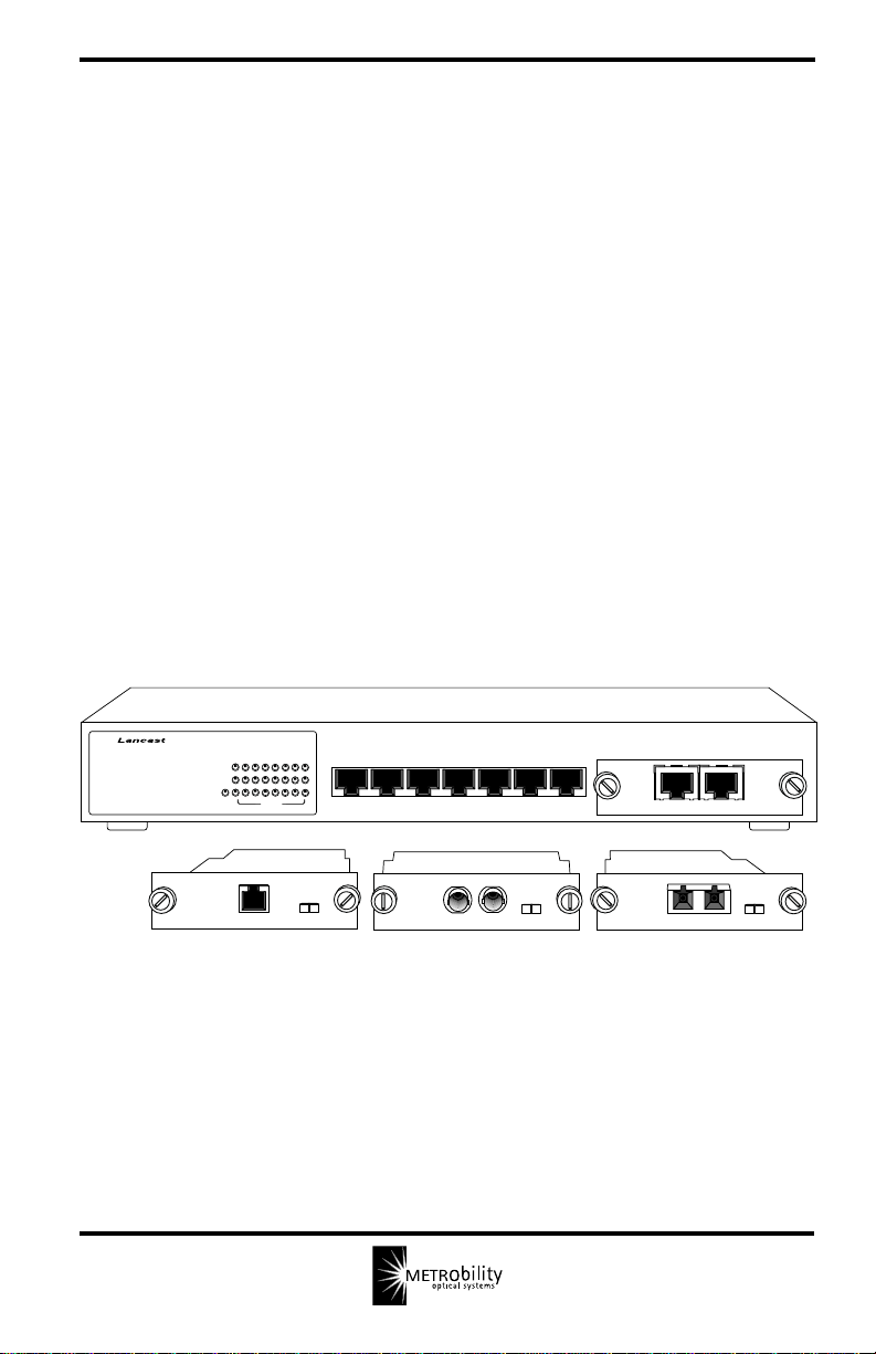
Designed to meet the needs of today’s growing networks, the Lancast 8-Port
CenturySwitch is a compact, low-cost switch featuring a unique replaceable port
module. The standard unit provides eight auto-negotiating 10/100 TX ports
including one modular port with two connectors to support either a crossover or
parallel connection.
The TX interface may be replaced by an optional 100Base-FX module. METRObility offers FX modules with SC, ST and MT-RJ multimode connectors in
addition to SC singlemode connectors which support network segments up to 15 or
40km. For added versatility, all FX modules include two user-selectable controls to
configure the port’s duplex mode and to set the backpressure/flow control.
By breaking up the collision domain and multiplying network performance, the
Lancast CenturySwitch delivers the ideal solution for easing network congestion
problems on existing shared-hub networks. Use the CenturySwitch to increase
overall network transmission speed and to improve efficiency to accommodate
high-bandwidth applications such as imaging, multimedia and CAD/CAM.
The CenturySwitch includes an universal internal power supply and is perfect for
stand-alone or rackmount use in any office environment.
Key Features
Designed for high-performance, versatility, and cost-effectiveness, the
CenturySwitch offers the following key features:
• Eight 10/100Mbps auto-negotiating RJ-45 ports including one MDI-X/
MDI-II modular port
• Optional multimode or singlemode 100Base-FX interface
• Full/half duplex switch on all FX modules
• Backpressure/flow control for half duplex on optional FX interfaces
• IEEE 802.3x compliant for flow control on all TX ports
• Diagnostic LED indicators
• Store-and-forward switching
• 148,800 packets/sec full-wire rate on 100Mbps mode forwarding and filtering;
14,880 packets/sec full-wire rate on 10Mbps mode forwarding and filtering
• Self-learning capability for up to 8K MAC addresses
• 512KB buffer memory
• Internal universal power supply
• Mountable in a standard 19-inch equipment rack
4 Product Overview
Page 5

Installation Guide
Follow the steps outlined in this section to install and start using your Lancast
CenturySwitch.
Unpack the Lancast CenturySwitch
Check that the following components have been included:
1
2
• 8-Port CenturySwitch 3508-11
• Rackmounting hardware: 2 mounting brackets, 4 screws
• Power cord
Your order has been provided with the safest possible packaging. Inspect
it carefully. If you discover any shipping damage, notify the carrier and
follow their instructions for damage and claims. Save the original
shipping carton if return or storage of the unit is necessary.
Choose a Location
The CenturySwitch is intended for use in normal office environments and
requires few restrictions on placement.
• Select a location that is within 6 feet of an AC power source and
less than 100 meters from servers, workstations or other connected
devices.
• Do not connect the unit to a power strip.
• Be sure the location allows for adequate ventilation with a
clearance of at least 1/2" on the sides of the unit.
• Be sure the location is as far away as possible from electrical noise
generating equipment such as copiers, electrostatic printers or
other motorized devices.
The CenturySwitch is designed to be mounted in a standard 19-inch
equipment rack. Use the rackmounting hardware included with the unit to
secure the mounting brackets to the unit. Use the separate screws
provided with the equipment rack to mount the unit in the rack. Be sure
that the mounting of the unit does not impose a hazardous condition due
to uneven mechanical loading.
The CenturySwitch can also be installed on a tabletop. For tabletop
installation, select a location with the power and ventilation requirements
cited above.
* #10-32 screw size is recommended.
*
Lancast 8-Port CenturySwitch 5
Page 6
3
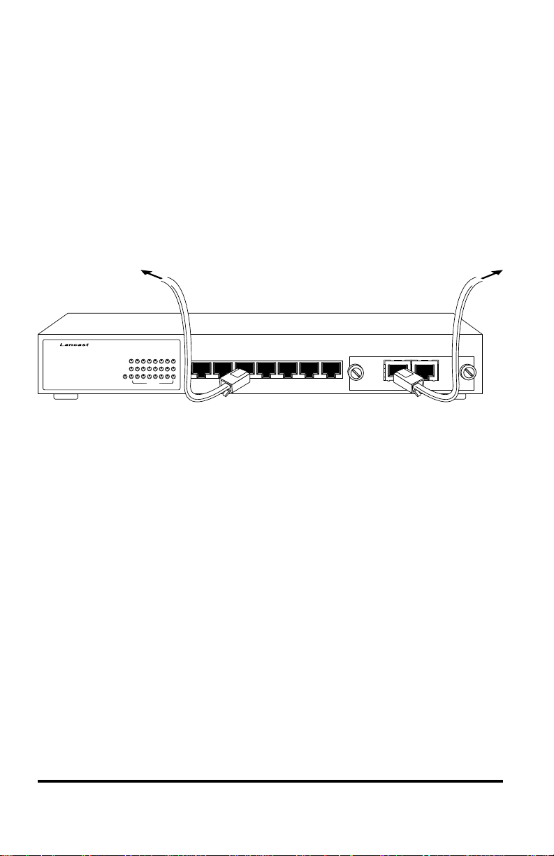
Connect to the Network
The Lancast CenturySwitch is compatible with both 10Base-T and
100Base-TX devices. Network connections are made by simply plugging
the cables into the RJ-45 port connectors on the front panel as shown in
the figure below. Each port supports a maximum segment length of 100
meters over Category 5 UTP cables for 100Base-TX segments and
Category 3, 4 or 5 UTP cables for 10-Base-T segments. Once power is
applied to the unit, use the individual Link/Act LEDs to verify correct
segment connectivity.
3508-11
CenturySwitch
®
®
Link/Act
100Mbps
Power
12345 678
FDX
10/100 Ethernet Switch
1x 2x 3x 4x 5x 6x
7x
Module Port 8
MDI-X MDI-II
Fixed Ports
The CenturySwitch provides seven fixed RJ-45 ports with connectors for
devices wired crossover. The ports are labeled 1x through 7x. These dualspeed ports are 10/100Mbps auto-sensing and will automatically detect
and operate at the speed of the connected device.
Module Port
Port 8 provides two RJ-45 connectors which support a device wired either
crossover (MDI-X) or parallel (MDI-II).
IMPORTANT: Do not connect devices to both the MDI-X and MDI-II
connectors at the same time. This can damage the unit and void its
warranty.
6 Installation Guide
Page 7

4
Install the Fiber Module (Optional)
Proceed to Step 5 if you are not using a fiber module.
The standard 10/100 TX module installed in the CenturySwitch may be
replaced by a 100Base-FX module. Refer to the listing inside the front
cover for all available options.
Set the Backpressure Jumper
Prior to installing the fiber module, you must set the flow control/
backpressure jumper labeled “JP2” on the printed circuit board. See the
diagram below for its location.
• Connect jumper pins 1 and 2 to enable backpressure.
• Connect jumper pins 2 and 3 to disable backpressure. (default)
1 2 3
JP2
Jumper JP2
Set the Duplex Mode Switch
Each fiber module can be configured for half duplex (HDX) or full
duplex (FDX) operation by means of the slide switch located on the front
panel. This switch should be set before applying power. The default
setting on the modules is FDX (full duplex).
Install the Module
To install your FX module, first remove the TX interface by turning the
two thumb screws counterclockwise and withdrawing the card. Replace it
with the new module. Tighten both screws firmly to attach the fiber
module to the CenturySwitch.
Lancast 8-Port CenturySwitch 7
Page 8

Connect to the Network
The 3508-04-F and 3508-07-F modules provide a pair of singlemode SC
connectors. The 3508-04-F supports a maximum segment length of 15km
and the 3508-07-F supports a maximum segment length of 40km.
3508-11
3508-11
3508-11
CenturySwitch
®
®
Link/Act
100Mbps
Power
12345 678
FDX
10/100 Ethernet Switch
1x 2x 3x 4x 5x 6x
100BASE-FX
Module Port 8
TX
RX
7x
The 3508-03-F and 3508-05-F modules provide a pair of multimode SC
and ST connectors, respectively. The 3508-0E-F provides a multimode
MT-RJ connector. These modules support a maximum segment length of
2km.
CenturySwitch
CenturySwitch
®
®
®
12345 678
Link/Act
100Mbps
Power
®
Link/Act
100Mbps
Power
FDX
123456 78
FDX
10/100 Ethernet Switch
1x 2x 3x 4x 5x 6x
10/100 Ethernet Switch
1x 2x 3x 4x 5x 6x
7x
7x
Module Port 8
TX
RX
100BASE-FX
Module Port 8
100BASE-FX HDX FDX
HDX FDX
HDX FDX
When making fiber optic connections with two cables, be sure that the
transmit (TX) connector on the CenturySwitch connects to the receive
(RX) connector of the device. Conversely, be sure that the transmit (TX)
connector of the device connects to the receive (RX) connector on the
CenturySwitch.
Once power is applied to the unit, use the Link/Act LED for Port 8 to
verify correct segment connectivity. The LED illuminates if an active
device is connected to the other end of the cable(s).
8 Installation Guide
Page 9

5
MADE IN TAIWAN
Apply Power
The CenturySwitch is equipped with an internal 100-240V, 50-60Hz,
25W power supply. When making power connections, connect the power
cord to the input jack located on the back of the switch before making the
AC connection to the outlet.
AC Line: 100-240V 50-60Hz
AC Power Socket
IMPORTANT: If the CenturySwitch loses power, wait at least 10
seconds before applying power again.
The CenturySwitch is shipped with a standard North American 3-pin
power cord which is UL (USA), CSA or CUL (Canada) listed or approved. For installation in regions outside of North America, replace the
power cord with a cord approved by the appropriate safety agencies. Any
cord used must have a CEE-22 standard V female connector on one end
and meet IEC 320-030 specifications. European power cords must be
harmonized and designated with a HAR marking on the cord jacket to
comply with the CENELEC Harmonized Document HD-21.
The CenturySwitch does not have a power switch. After connecting the
unit to the AC receptacle, check that the PWR (power) LED is illuminated. A steady green light indicates the unit is receiving power.
Once power is applied to the unit, use the individual Link/Act LEDs on
the front panel to verify correct segment connectivity.
Lancast 8-Port CenturySwitch 9
Page 10

10 Installation Guide
Page 11

User Guide
This section contains more detailed information regarding the operating
features of the Lancast CenturySwitch.
LED Operation
The functional descriptions of the LED indicators are listed below. The port LEDs
report the status of their corresponding ports labeled 1 through 8.
emaNDELroloCsutatSnoitcnuF
DELmetsyS
rewoPneerGNO.NOderewopsitinU
sDELtroPreP
tcA/kniLneerG
spbM001neerG
XDFrebmA
CenturySwitch
3508-11
NO
gniknilB.tneserpsiciffartXT
FFO
NO.evitcasideepsspbM001
FFO.evitcasideepsspbM01
NO.evitcasiedomxelpudlluF
FFO.evitcasiedomxelpudflaH
Link/Act
100Mbps
Power
etomerhtiwnoitcennoC
.doogsiecived
etomerotnoitcennocoN
.ecived
123456 78
FDX
Lancast 8-Port CenturySwitch 11
Page 12

Troubleshooting
Cabling Problems
Improper cabling is the primary cause of most network problems, particularly for
100Base-TX and 100Base-FX networks. Use only the specified twisted-pair or fiber
optic cables to avoid most cabling problems.
• Flat telephone extension cables, or Category 3 wires, are not the same as
Category 5 twisted-pair cables and will not function on Fast Ethernet networks.
• There is a wiring problem if the Link/Act LED does not illuminate when the
RJ-45 plug from a workstation is inserted into the port jack. Correct the
break in the cable or replace the cable before proceeding.
• If a workstation (workstation A) does not function while workstations connected to other ports on the CenturySwitch operate normally, remove an RJ45 plug from a functioning port with a functioning workstation (workstation
B) and insert it into the suspect port. If workstation B still works, the problem may be in workstation A or in the wiring. However, if workstation B
does not work, the CenturySwitch may have a defective port. Even if you
suspect a defective port, continue testing. Improperly wired workstations
may appear functional, especially if they are located near the switch. Sometimes a port connected to an improperly wired workstation functions marginally while another port does not work at all.
• Once you have established that the CenturySwitch is working properly , check all
wiring between it and the malfunctioning workstation. Be sure that the transmit
(TX) and receive (RX) cables are not crossed. The transmit cable from the workstation should connect to the receive connector of the switch and the transmit cable
from the switch should connect to the receive connector of the workstation.
• Use a continuity checker to ensure that wires do not have any breaks. By
shorting together the two wires at the end of a pair, you can use the continuity
checker at the other end. Also check that there are no shorts between wires.
Workstation Problems
Most non-cabling problems result from improper configuration of the network
interface card (NIC) and its corresponding driver. Observe the following points:
• Like other add-on cards in the workstation or server, the NIC must have a
unique memory address, I/O address and interrupt. The settings on a
particular card must not conflict with the settings on any other card in the
same station. Refer to the user’s manuals of your NIC, computer and
network operating system to determine the proper configuration.
12 User Guide
Page 13

• The mode (half duplex or full duplex) and speed (10Mbps or 100Mbps) of
the NIC setting must match the mode and speed setting of the corresponding
port of the switch. For NWay Auto-Negotiation setting, both link partners
will adjust to the highest allowable speed and mode operation.
Other Problems
Other specific problems may be diagnosed by using the LEDs as described below.
Power LED is OFF when CenturySwitch is connected to the AC source
• Defective fuse
• Incorrect AC voltage
• Defective switch
Link/Act LED is OFF at a port
• Faulty node or wiring connection (when RJ-45 plug is inserted, a clicking
sound should be heard)
• No link signal is received from the remote device
CenturySwitch does not work
If the switch does not function or is experiencing interference (i.e., your site is
located near a radio station, transmitter, etc.), try using shielded twisted-pair (STP)
cables instead of UTP cables.
Self-diagnostic test
• The CenturySwitch performs a self-diagnostic test at power on; LED
indicators go to their normal status if no problem occurred.
• To reset or restart the CenturySwitch, unplug it from the AC source and wait
10 seconds before applying power again.
CAUTION: Circuit devices are sensitive to static electricity which can damage
their delicate electronics. Dry weather conditions or walking across a carpeted
floor may cause you to acquire a static electric charge.
To protect your device, always:
• Touch the metal chassis of your computer to ground the static electrical
charge before you pick up the device.
• Pick up the device by holding it on the left and right edges only.
Lancast 8-Port CenturySwitch 13
Page 14

Topology Solutions
CenturySwitch
CenturySwitch
CenturySwitch
14 User Guide
Intelligent
7500 Chassis
Copper
Fiber Optic
100Mbps
Enterprise Switch
Page 15

Technical Specifications
Data Rate
10Base-T ports ___________________ 10Mbps half duplex; 20Mbps full duplex
100Base-TX ports_______________ 100Mbps half duplex; 200Mbps full duplex
100Base-FX ports _______________ 100Mbps half duplex; 200Mbps full duplex
Switching Performance
Buffer memory _____________________________________ 512KB for 8 ports
Packet filtering/forwarding rate _____________ 148,800 packets/sec @100Mbps
_______________ 14,880 packets/sec @10Mbps
MAC addresses__________________________________________________8K
Network Connections
Twisted-Pair Interface
Connector _______________________________________Shielded RJ-45, 8-pin
Supported link length __________________________________________ 100m
Cable type (10Mbps segments) _____________________ Category 3,4 or 5 UTP
(100Mbps segments) _________________________ Category 5 UTP
Multimode Fiber Optic Interface
Connector __________________________________________ SC, ST or MT-RJ
Supported link length ______________________________ up to 2km full duplex
Cable type ___________________________ 50/125, 62.5/125 or 100/140µm F/O
Singlemode Fiber Optic Interface
Connector ______________________________________________________SC
Supported link length __________________ up to 15km full duplex (3508-04-F)
__________________ up to 40km full duplex (3508-07-F)
Cable type ______________________ 8.3/125, 8.7/125, 9/125 or 10/125µm F/O
Power Requirements
Auto-sensing_____________________________100 - 240V AC, 50/60 Hz, 25W
Environmental
Operating temperature ____________________________________0°C to 50° C
Storage temperature ____________________________________-25° C to 60° C
Operating humidity__________________________5% to 90% (non-condensing)
Lancast 8-Port CenturySwitch 15
Page 16

Physical
Dimensions _________________________________ 13" W x 6.75" D x 1.75" H
Weight________________________________________________________ 4 lb
Regulatory
Compliance______________________________ IEEE 802.3u and 802.3x, TUV
Safety ___________________________________________ UL, CSA, EN60950
EMC _________________ FCC Part 15, Class A; EN55022 Class A; EN50082-1
16 User Guide
Page 17

Product Safety, EMC and Compliance Statements
This equipment complies with the following requirements:
•UL
• CSA
• TUV
• EN60950 (safety)
• FCC Part 15, Class A
• EN55022 Class A (emissions)
• EN50082-1 (immunity)
• IEEE 802.3
• IEEE 802.3u
• IEEE 802.3x
• IEC 825-1 Classification
• Class 1 Laser Product
This product shall be handled, stored and disposed of in accordance with all governing and applicable safety and environmental regulatory agency requirements.
The following FCC and Industry Canada compliance information is applicable to
North American customers only.
USA FCC Radio Frequency Interference Statement
This equipment has been tested and found to comply with the limits for a Class A
digital device, pursuant to Part 15 of FCC Rules. These limits are designed to provide
reasonable protection against harmful interference when the equipment is operated in
a commercial environment. This equipment generates, uses and can radiate radio
frequency energy, and if not installed and used in accordance with the instruction
manual, may cause harmful interference to radio communication. Operation of this
equipment in a residential area is likely to cause harmful interference in which case
the user will be required to correct the interference at his own expense.
Caution: Changes or modifications to this equipment not expressly approved by
the party responsible for compliance could void the user’s authority to operate the
equipment.
Canadian Radio Frequency Interference Statement
This Class A digital apparatus meets all requirements of the Canadian Interference-Causing Equipment Regulations.
Cet appareil numérique de la classe A respecte toutes les exigences du Réglement
sur le matériel brouilleur du Canada.
Lancast 8-Port CenturySwitch 17
Page 18

Warranty and Servicing
METRObility Optical Systems, Inc. warrants the Lancast CenturySwitch to be in
good working order for a period of three years from the date of METRObility
shipment. Should the unit fail anytime during said three-year period, METRObility
will, at its option, replace or repair the product. This warranty is limited to defects
in workmanship and materials and does not cover damage from accident, disaster,
misuse, abuse or unauthorized modifications. Under no circumstances will
METRObility be liable for any damages incurred by the use of this product
including, but not limited to, lost profits, lost savings, and any incidental or
consequential damages arising from the use of, or inability to use, this product.
If the product was purchased from an authorized METRObility dealer, limited
warranty service may be obtained by returning the product to the dealer. Return
the product in its original shipping container (or equivalent), pre-insured, and with
proof of purchase.
18 User Guide
Page 19

Lancast 8-Port CenturySwitch 19
Page 20

25 Manchester Street, Merrimack, NH 03054 USA
tel: 603-880-1833 • fax: 603-594-2887
www.metrobility.com
5660-350001-001 D
8/01
 Loading...