


Metro C5T5AX-DSB Installation Manual
T-SERIES HOT
FOOD HOLDING
CABINETS
INSTRUCTIONS
FOR USE
THIS MANUAL COVERS CABINETS
WITH ELECTRICAL
RATINGS OF: 120V 1400W &
220-240V 1176-1400W
When ordering electrical parts, always confirm the rating listed on cabinet data plate on
back of cabinet.
Differences in voltage, amps or wattage are
listed with BOLD TEXT in replacement part
descriptions.
L01-459 Rev.H
07/2016
InterMetro Industries Corporation
North Washington Street, Wilkes-Barre, PA 18705
For Product Information Call: 1-800-992-1776,
Visit Our Web Site: www.metro.com
Metro Heated Cabinets are for
Hot Food Holding applications only
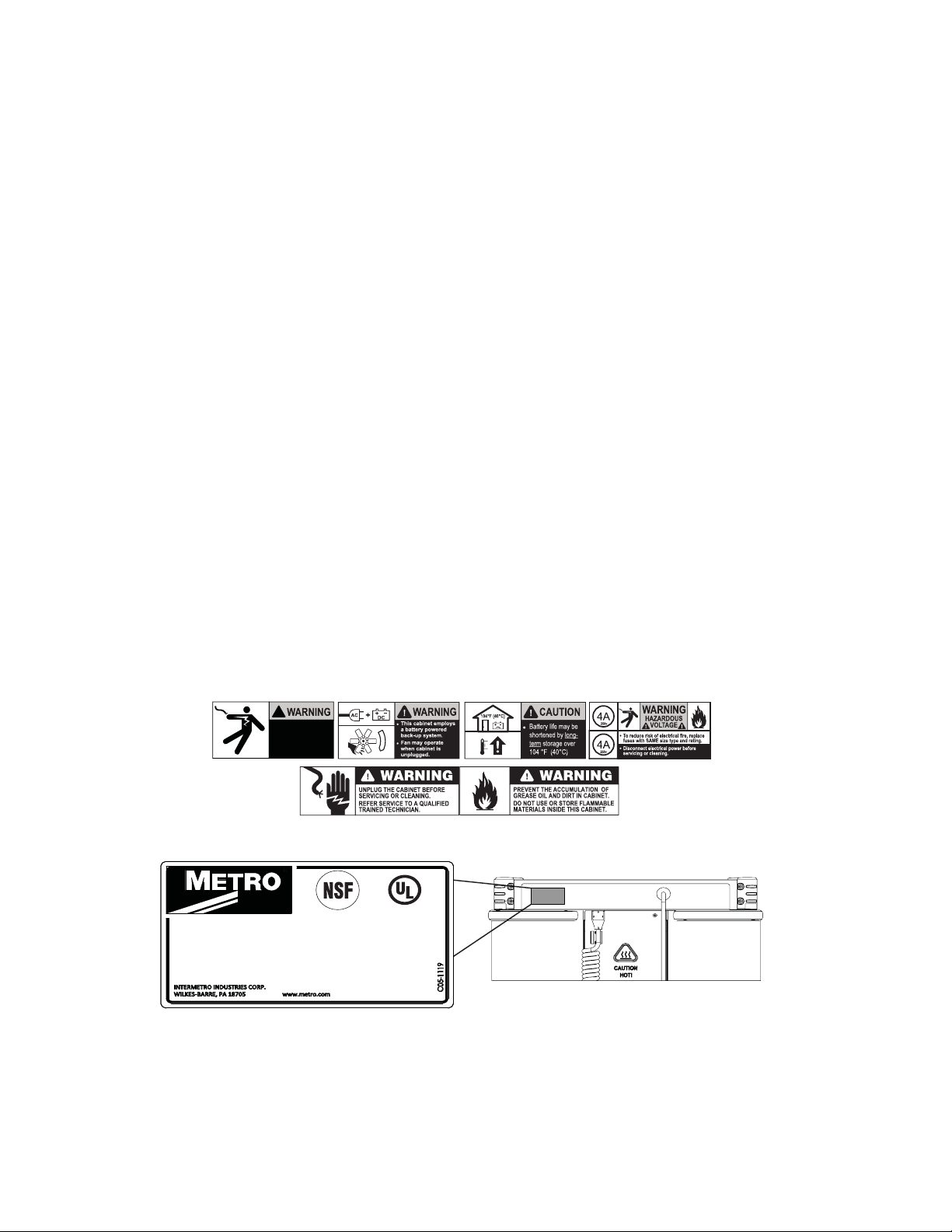
TABLE OF CONTENTS
SAFETY INFORMATION ...............................................................................................................................................................................................................2
SAFETY SYMBOLS .........................................................................................................................................................................................................................2
IDENTIFY YOUR CABINET ...........................................................................................................................................................................................................2
PRODUCT FEATURES ...................................................................................................................................................................................................................3
INSTALLATION AND SETUP .......................................................................................................................................................................................................5
OPERATING INSTRUCTIONS (DIGITAL CONTROLLER) .....................................................................................................................................................8
OPERATING INSTRUCTIONS (ANALOG CONTROLLER) ....................................................................................................................................................11
HANDLING INSTRUCTIONS FOR TRANSPORTING CABINET ..........................................................................................................................................12
CARE AND MAINTENANCE ........................................................................................................................................................................................................12
BASIC TROUBLESHOOTING .......................................................................................................................................................................................................13
SERVICE AND REPLACEMENT PARTS .....................................................................................................................................................................................14
SERVICE AND REPLACEMENT PARTS (CIRCUITS) ...............................................................................................................................................................18
WARRANTY .....................................................................................................................................................................................................................................22
SAFETY INFORMATION
WARNING: This cabinet is only for hot food holding applications.
WARNING: Follow all food safety guidelines. Pre-heat the cabinet to the desired temperature before placing hot cooked
food into the cabinet. Food must be at the appropriate temperature before being placed into cabinet. Use a
food probe to check internal food temperature - the cabinet temperature is not necessarily the internal food
temperature.
WARNING: Only factory approved service agents should attempt to service, repair or replace electrical components,
wiring or power cord.
WARNING: Unplug the cabinet before cleaning or servicing. Do not wash the cabinet with a water jet or high pressure
water, do not hose wash/spray interior.
WARNING: Food Service Equipment must be electrically grounded. Failure to ground Food Service Equipment may
result in serious injury or death from electrical malfunction.
CAUTION: Do not spray or pour water into the top of the cabinet (control enclosure). Unplug the cabinet before
cleaning and then wipe with a damp cloth and dry with a towel. Use only cleaning agents approved for
stainless steel.
SAFETY SYMBOLS
!
HAZARDOUS
VOLTAGE !
Disconnect power
before servicing or
cleaning.
IDENTIFYING YOUR CABINET
®
C
®
US
HOT FOOD HOLDING CABINET
MODLE NO : C5TX-XXXX
SERIAL NO : C5TXXXX
MFG DATE : MM/YR
ELECTRICAL :
XXXV XXHz XXXW
For future reference, note the serial and model number found on the data plate of the cabinet here:
Serial number ________________________________
Model number ________________________________
Date the cabinet was put into service _______________________________
Fill out and return the warranty card located at the back of this manual.
LISTED 465C
2
PART NUMBERING
CABINET NAME
T = T-SERIES
PRODUCT FEATURES
C5 T 9 D
__
CABINET HEIGHT
9 = FULL
8 = 5/6
5 = 1/2
CABINET TYPE
D = DUAL CAVITY
BLANK = SINGLE CAVITY
ELECTRICAL RATING
X = 220-240V
BLANK = 120V
_
_
_
X
_
-
D S B
_
_
_A _
ACCESSORIES
SLIDES
L = ADJUSTABLE LIP LOAD
18x26 & 12x20
B = ADJUSTABLE BOTTOM LOAD
18x26 & 12x20
F = FIXED LIP LOAD
GN & 12x20 only
MATERIAL
S = STAINLESS STEEL
CONTROLLER
D = DIGITAL
A = ANALOG
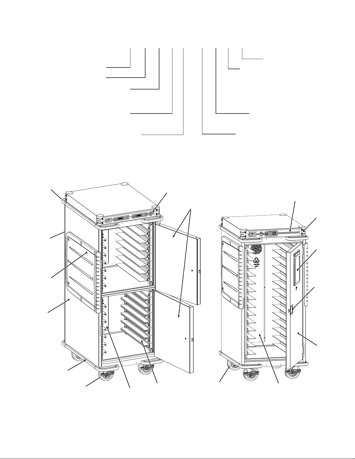
Molded
Handle
Rear Push
Handle
(not on
1/2 Height
Cabinets)
Armour
Panel
Shell Body
Digital Control
Panel
Door
Analog Control
Panel
Molded
Corners
Info
Panel
Door
Latch
Door
Strip Bumper
(2) Brake Caster
- Front
Air Chimney
Slides
(2) Swivel Caster
- Rear
3
Air Chimney
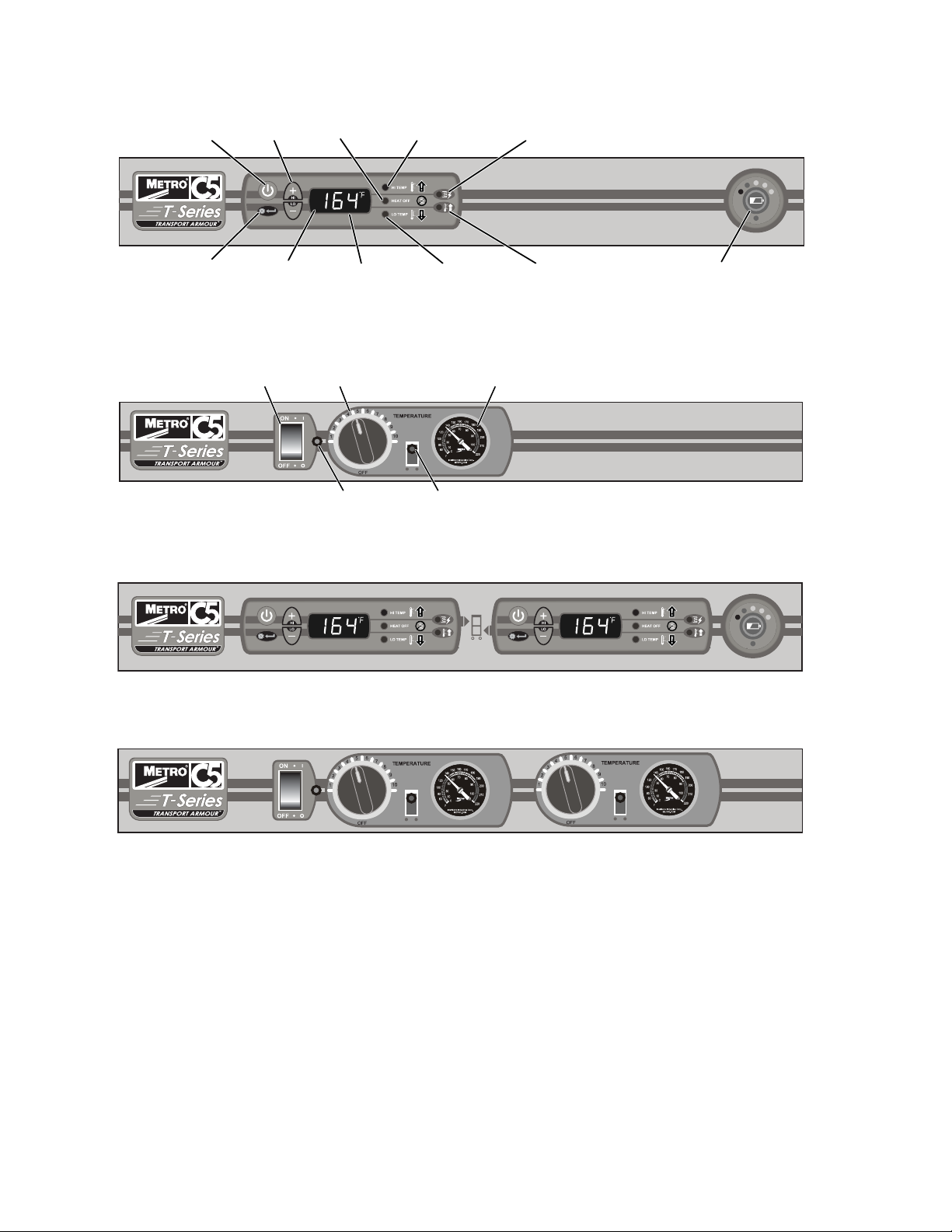
Digital Controller (Single Cavity Cabinets)
Power
Switch
Settings/Enter
Switch
Selection
Switch
Temperature
Range
HEAT OFF
Indicator
Temperature
Display
Analog Controller (Single Cavity Cabinet)
Power
Switch
Temperature Range
Setting
Power Indicator Light
(RED)
Digital Controller (Dual Cavity Cabinets)
HI Temperature
Alarm Indicator
LO Temperature
Alarm Indicator
Thermometer
(°F and °C)
Heat Indicator Light
(RED)
ELEMENT
Indicator
PREHEAT
Indicator
Battery Charge
Indicator
Top Compartment Controller
Analog Controller (Dual Cavity Cabinet)
Top Compartment Controller Bottom Compartment Controller
Bottom Compartment Controller
4
INSTALLATION AND SETUP
NOTE: The First 4 steps below are common to both Analog and Digital cabinets.
1. Check for Shipping Damage: Check the packaging and cabinet for shipping damage before and after unloading the
unit, and after removing all packaging materials.
2. The receiver of this product is responsible for ling freight damage claims. This equipment must be opened
immediately for inspection. All visible damage must be reported to the freight company within 48 hours and must be
noted on freight bill at the time of delivery.
3. Concealed damage is your responsibility — you must advise the carrier of any loss or damage within 15 days after
receipt of the cabinet. If there is damage, retain the original packaging for inspectors.
4. After unpacking the cabinet, remove all packing material from the inside as well as outside of the unit.
5. The power cord is located at the back of the cabinet as shown in Figure 1.
6. Refer to the data plate located near the power cord for the electrical specications of cabinet as shown in Figure 2.
With the POWER switch OFF, plug the cord into the appropriate rated, grounded receptacle.
Cabinets rated at 120V 1400W must be plugged into either a 15 amp or 20 amp 125 VAC receptacle.
Cabinets rated at 220-240V 1176-1400W must be plugged into a 15 amp 250 VAC receptacle.
POWER CORD LOCATION ON CABINET
FIGURE 1:
C5 TSERIES WALL RECEPTACLES
FIGURE 2:
WARNING: Do not allow combustible materials to be stored or accumulate on, under or next to the cabinet. Do not
block any ventilation louvers or slots.
CAUTION: C5 T-Series cabinets (Polymer Armour panels on the sides) must not be placed next to char broilers
or Allow 18" (46cm) between the Armour panels and any cooking equipment. Do not allow hot kitchen
equipment whose surfaces exceed 200°F (90°C) to touch the panels.
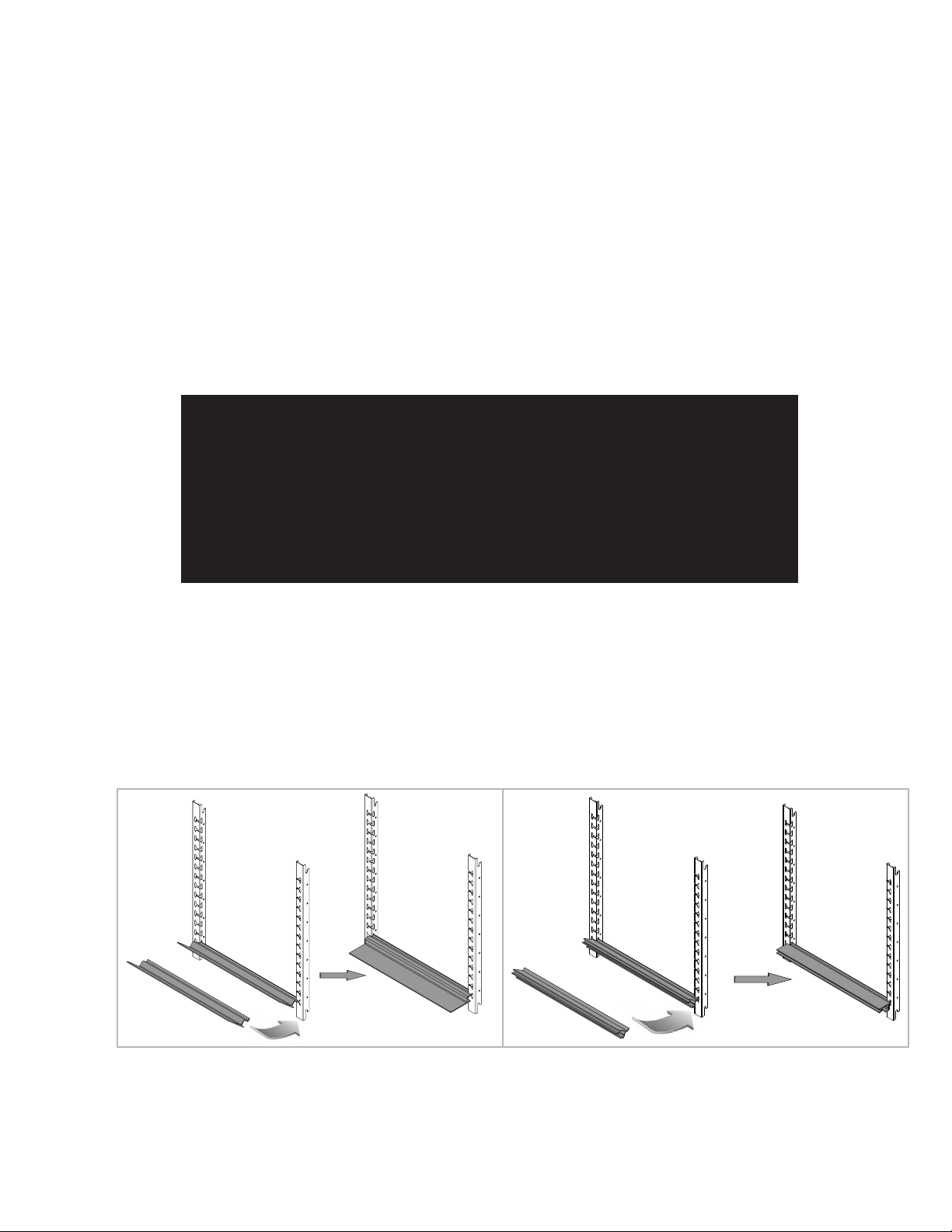
Slide Installation Adjustable on Uprights (Bottom Load and Lip Load)
BOTTOM LOAD LIP LOAD
5
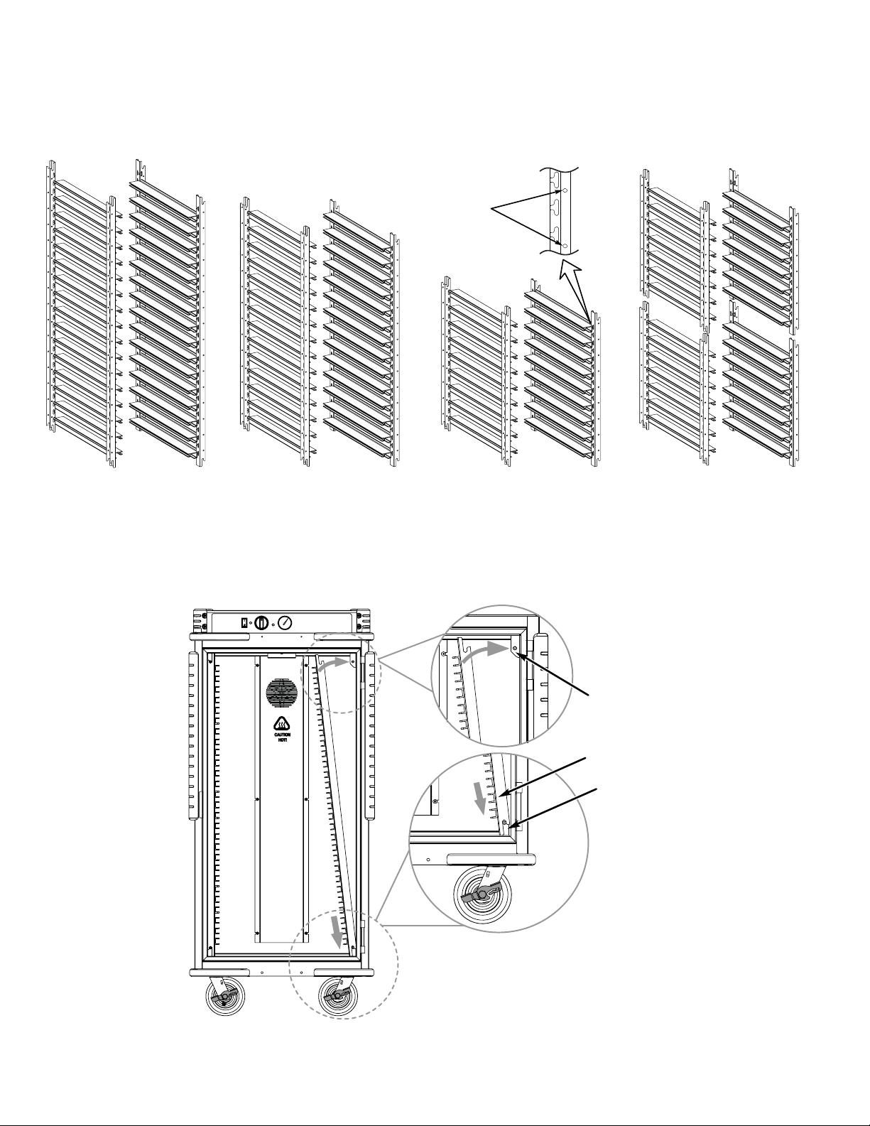
Maximum Capacity of Adjustable Slides (Lip and Bottom Loads)
NOTE: Only lip load capacities are shown below. Bottom loads have the same capacities.
SiteSelect™
feature make
slide installation
easier.
FULL HEIGHT SINGLE
16 Levels
Position from Bottom
Lip Load Part No. C5T-LL-9, 1PR
Bottom Load Part No. C5T-BL-9, 1PR
Installation of Fixed Slide Racks
5/6 HEIGHT CABINET
14 Levels 9 Levels
Position from Bottom
Lip Load Part No. C5T-LL-8, 1PR Lip Load Part No. C5T-LL-5, 1PR Lip Load Part No. C5TD-LL-9, 2PR
Bottom Load Part No. C5T-BL-8, 1PR Bottom Load Part No. C5T-BL-5, 1PR
1/2 HEIGHT CABINET
Position from Bottom
DUAL CAVITY
7 Levels (14 Total)
Position from Bottom
Bottom Load Part No. C5TD-BL-5, 2PR
Top Mounting
Bracket
Fixed Slide
Bottom Mounting
Bracket
A
NOTE: Door not shown for clarity.
6
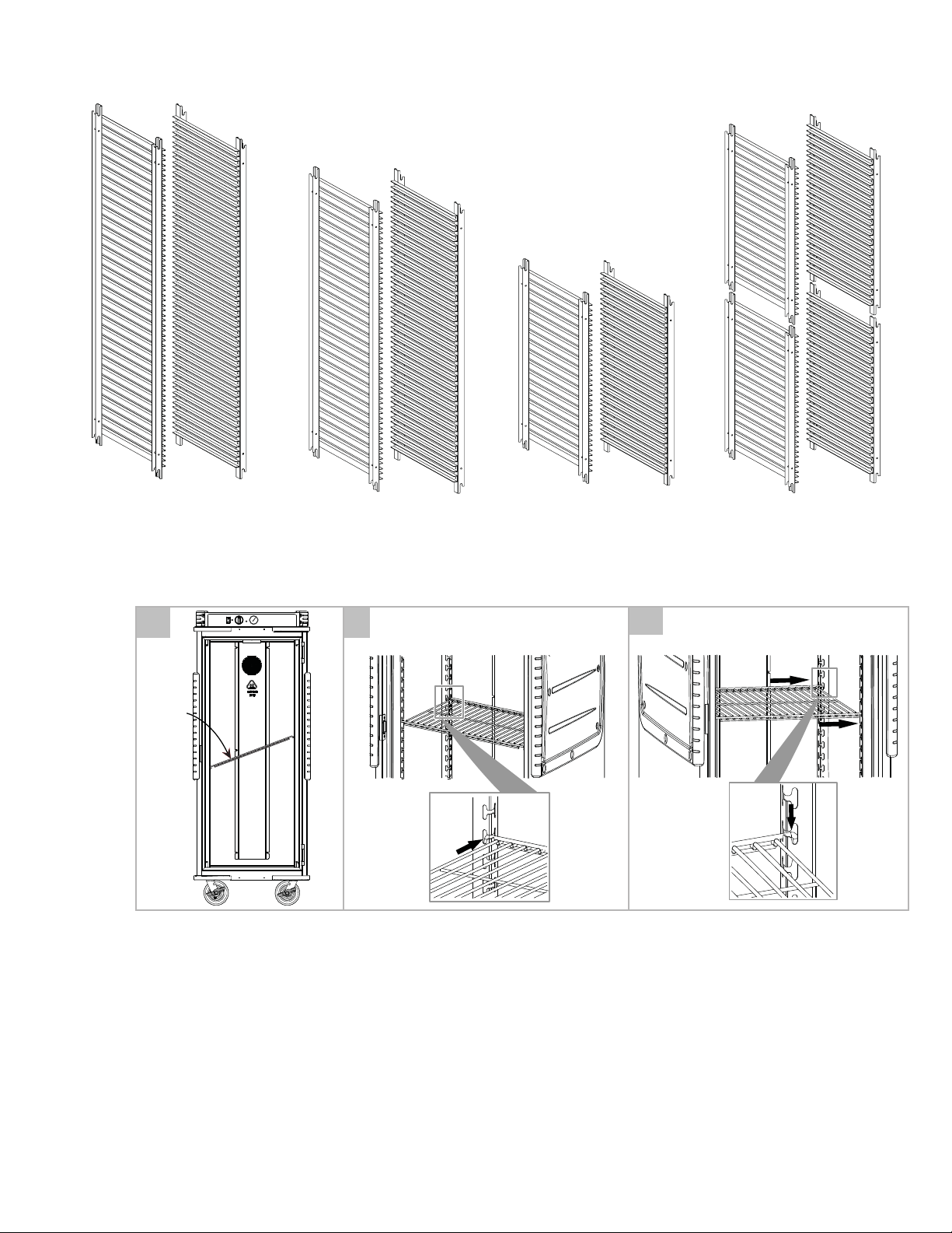
Fixed Lip Load Slide Congurations
FULL HEIGHT
1-Piece Construction
Part No. C5T-9FXSLIDE
Wire Shelf Installation
1
Wire-
Shelf
5/6 HEIGHT
1-Piece Construction
Part No. C5T-8FXSLIDE
Insert left side of wireshelf into upright at
2
an angle and then lower right side to level
and shift shelf to t into right side upright.
1/2 HEIGHT
1-Piece Construction
Part No. C5T-5FXSLIDE
DUAL CAVITY
1-Piece Construction (2 Pairs)
Part No. C5T-9DCFXSLIDE
NOTE: Wireshelf must be used with
3
cabinet uprights
7
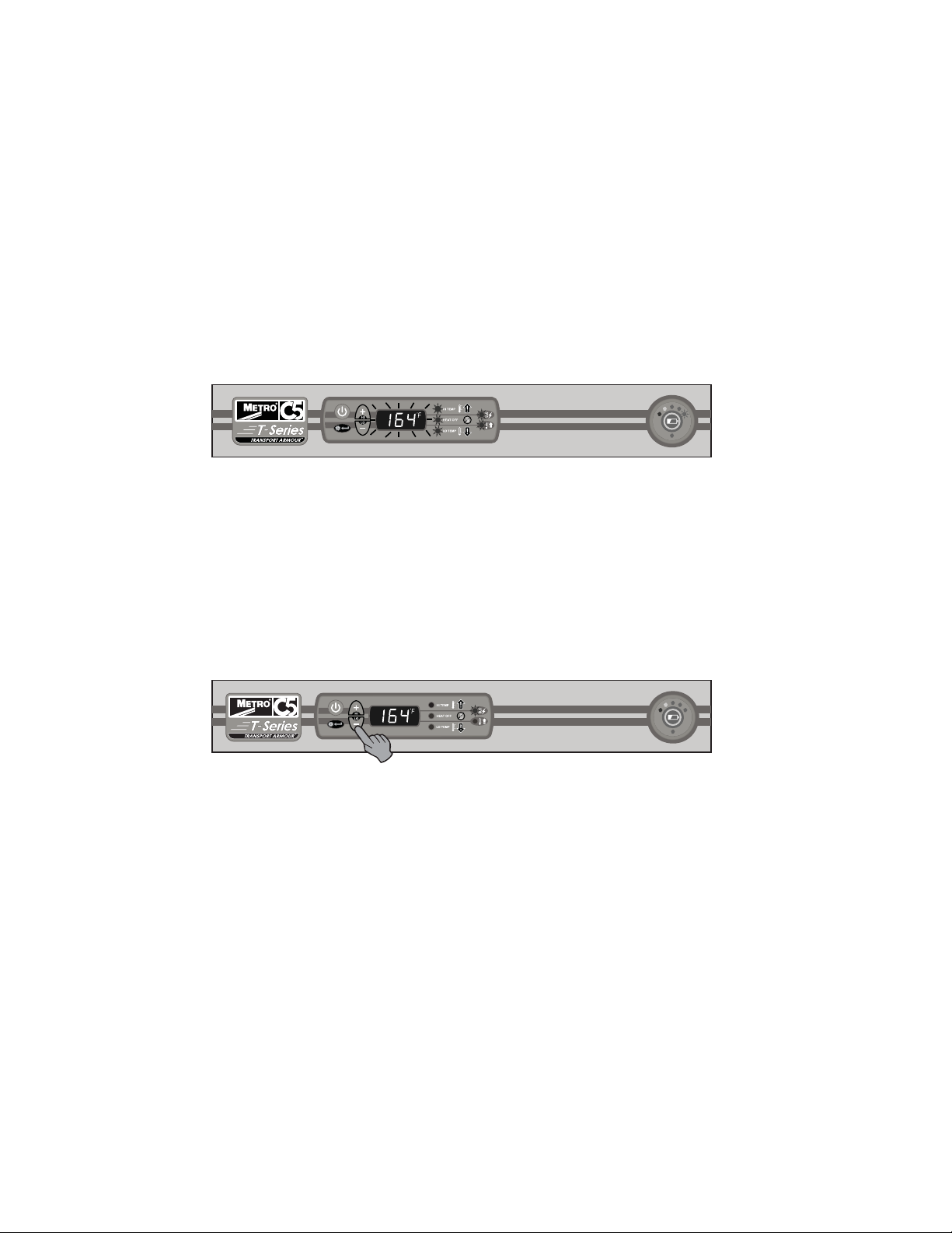
OPERATING INSTRUCTIONS DIGITAL CONTROLLER
NOTE: Before using your cabinet for the rst time, heat the cabinet to maximum temperature for 15 minutes to burn o
oils on stainless from manufacturing process. During this process slight smoke may be seen.
Power-Up and Pre-Heat
t When the cabinet is switched on, all LEDs and display segments illuminate (blinking) for 3 seconds.
t The display then shows the set point (blinking) for 3 seconds, followed by current temperature.
t The preheat indicator light turns o after the temperature set point is reached. Set point range is 85 – 200 °F
(29-93 °C) and “---” indicates one step below 85 °F (29 °C).
t If the set point is “---” (heat o ) the pre heat LED will be o. The “heat o” LED will be on.
NOTE: The current temperature scale LED (°F or °C) remains illuminated whenever the cabinet is turned on. The
“element indicator” LED remains on whenever the circuit is energized.
t During initial pre-heat, the “lo temp” alarm is disabled.
t When plugged in and powered-on, the “Power” display shows the current charge status of the battery. When
charging, the uppermost led blinks in 1 second intervals, while all LEDs below it remain on continuously. When the
battery is fully charged, all power LEDs are lit continuously.
1. Allow the cabinet to pre-heat without food for 30 minutes to an hour. The pre-heat time required to reach the
temperature set point is dependent on the set point, the size of the cabinet, the door type (single or dual) and the
temperature of the room the cabinet is in.
Steady State Operation
t Press and release the “+ or –” buttons at any time to change the set points. The rst push recalls and displays
the current set point. If a button is pressed again within a 4 second period, the set point will be changed by a 1
degree increment. The set point will be displayed for 4 seconds, then shows the current temperature display.
t Press and hold the “+ or –” buttons to recall and display the current set point for 4 seconds. The set point will then
change in 1 degree increments every ½ second for the rst 5 seconds, then increase in 10 degree increments
every ½ second until the button is released. The set point will be displayed for 4 seconds, then shows the current
temperature display.
Unplugged Operation
t When cabinet is unplugged the system begins operation on battery power.
Temperature monitoring and air circulation continues up to (3 hours) after the cabinet is un-plugged.
Cabinet displays are turned on when the cabinet is unplugged.
If additional runtime is desired, press power switch to engage controller and fan.
t Display the current cabinet temperature: Press the “+ or –” button. The display will show the current temperature
for as long as the button is depressed. Temperature set points cannot be changed while cabinet is unplugged.
t Display the battery charge status: Press the “battery” button. The display will show the current charge level for as
long as the button is depressed.
t Low Temp Alarm: If the cabinet temperature drops below the alarm set point for more than 5 minutes during
operation, the display will begin to blink “___”, and the “LO TEMP” LED will illuminate (blinking). This will repeat
every 10 seconds.
t Hi Temp Alarm: If the cabinet is in “HEAT OFF” mode and the temperature rises above the alarm set point for
more than 5 minutes during operation, the display will begin to blink “---”, and the “HI TEMP” LED will illuminate
(blinking). This will repeat every 10 seconds.
NOTE: Audio (if enabled), Low temp Alarm: (3) 1/2 second beeps, repeating every 10 seconds.
t Average charging time = 1 hour for single cavity and 1
1
/2 hours for dual cavity.
8