

Page 1
Metro™ 1800 Series
Mobile Workstation
Operations Manual
L01-503 RevA
Copyright © 2013
InterMetro Industries Corporation
www.metro.com
Page 2

THIS PAGE INTENTIONALLY LEFT BLANK
Page 3

Notice:
InterMetro Industries Corporation reserves the right to make improvements or changes to the products described in this manual at
any time without notice.
While reasonable efforts have been made in the preparation of this document to assure its accuracy, InterMetro Industries
Corporation assumes no liability resulting from any errors or omissions in this document, or from the use of the information
contained herein.
Copyright Notice:
This manual is copyrighted. All rights reserved. This manual may be printed for personal use only. This manual, whole or in part,
may not be copied, photocopied, reproduced, translated, or reduced to any electronic medium or machine-readable form for
distribution. This manual, whole or in part, may not be modified without prior consent, in writing, from InterMetro Industries
Corporation.
Copyright © 2013 by InterMetro Industries Corporation, 651 North Washington Street, Wilkes-Barre, PA 18705, U.S.A.
• Metro is a registered trademark of InterMetro Industries Corporation.
• Windows is a registered trademark of Microsoft Corporation in the United States and other countries.
• Velcro is a registered trademark of Velcro Industries B.V.
Contact Information:
InterMetro Industries Corporation
North Washington Street
Wilkes-Barre, PA 18705
Phone: 1-800-992-1776
http://www.metro.com/support
FCC Information:
This device complies with FCC Rules, part 15. Operation is subject to the following conditions:
1. This device may not cause harmful interference, and
2. This device must accept any interference that may be received, including interference that may cause undesired
operation.
Notice: This equipment has been tested and found to comply with the limits for a Class A digital device, pursuant to part 15 of the
FCC rules. These limits are designed to provide reasonable protection against harmful interference when the equipment
is operated in a commercial environment. This equipment generates, uses, and can radiate radio frequency energy and,
if not installed and used in accordance with the instruction manual, may cause harmful interference to radio
communications. Operation of this equipment in a residential area is likely to cause harmful interference in which case
the user will be required to correct the interference at the user’s expense.
Warning: Changes or modifications to this device not expressly approved by InterMetro Industries Corporation could void the
user’s authority to operate this equipment.
Shielded cables must be used with this unit to ensure compliance with the FCC Class A limits.
Industry Canada:
This class A digital apparatus meets all requirements of the Canadian Interface Causing Equipment Regulations. Operation is
subject to the following two conditions:
1. This device may not cause harmful interference, and
2. This device must accept any interference received, including interference that may cause undesired operation.
Regulatory Compliance
This system was tested and complies with UL 60601-1, CAN/CSA C22.22 No.601.1 and IEC/EN 60601-1-1 medical safety
standards.
MetroTM 1800 Series Mobile Workstation Operations Manual, L01-503
3
InterMetro Industries Corporation
Page 4
Symbol Explanations
The product is CSA certified with respect to electrical shock, fire and mechanical hazards only in
accordance with UL 60601-1, CAN/CSA C22.22 No.601.1 and IEC/EN 60601-1-1 as Type B
Patient Care Medical Equipment suitable for use in patient vicinity.
Type B Applied Part
Attention, consult accompanying documents
Important Safety Instructions
This document contains important safety and operating instructions for the MetroTM 1800 Series Mobile Workstations. Please read
all instructions and cautionary markings on the Mobile Workstation before putting it into service.
Caution:
User maintenance consists of cleaning, minor external adjustments, periodic tightening of fasteners and the like. For
safety purposes, any and all servicing other than the procedures detailed in the Maintenance section of this manual
must be performed by qualified service personnel only. For all service items, please contact InterMetro Customer
Service.
Caution:
Do not operate a Metro
fallen down stairs, or otherwise physically damaged. Please have a qualified service person inspect all components
of the Mobile Workstation for any performance or safety hazard prior to putting it back into service.
Caution:
The Metro 1800 Series Mobile Workstation is not designed for use as a general purpose equipment cart. Please do
not apply heavy loads to the cart top surface. The maximum design load (safe working load limit) for the Mobile
Workstation is 5 lbs.
Caution:
Ensure that the AC power supply cord is located and secured so that it will not be stepped on, tripped over, or
otherwise subjected to damage or stress. Please secure the AC power cord plug in the retaining clips provided on the
TM
Metro
1800 Series Mobile Workstation when it is unplugged from the AC outlet in order to prevent accidental
tripping and physical damage to the cord plug or electrical insulation.
To prevent damage to any cords or connectors when disconnecting, always grasp and pull by the connector and not
the cord.
Do not operate the Metro
damaged component immediately. Contact InterMetro Customer Service for replacement parts and service.
Caution:
To reduce the risk of electric shock, unplug the Metro
and switch the ON/Extended Storage Switch to the Extended Storage (OFF) position before attempting any
maintenance or cleaning. Turning off computers or disconnecting the AC power cord alone will not reduce the risk of
electric shock because the Power Supply is internally powered by a battery.
Warning: Risk of Electric Shock - DC voltage output power supply
The AC power cord is the only means to disconnect the Metro
grid (mains). The ON/Extended Storage Switch on the DC power supply does not disconnect from main power.
On the other side, the power supply employs a battery to provide mobile DC output power. Low voltage (10-16 VDC)
DC power is available from the power supply, even when the AC cord is disconnected from an AC outlet. To remove
DC power, put the ON/Extended Storage Switch in the Extended Storage (OFF) position.
TM
1800 Series Mobile Workstation if it has received a severe impact, been knocked over,
TM
1800 Series Mobile Workstation with damaged cords or connectors. Please replace the
TM
1800 Series Mobile Workstation AC cord from an AC outlet
TM
1800 Series Mobile Workstation from the AC power
4
Metro
TM
1800 Series Mobile Workstation Operations Manual
InterMetro Industries Corporation
Page 5

Warning: Risk of Electric Shock - AC inverter power supply
The AC power cord is the only means to disconnect the Metro
grid (mains). The ON/OFF switch on the Fuel Gauge controlling the AC power supply does not disconnect from main
power.
On the other side, the power supply employs a battery to provide mobile AC output power. High voltage and current
AC voltage (120 or 230 VAC nominal) power is available from the power supply, even when the AC cord is
disconnected from an AC outlet. To remove AC power, press the ON/OFF switch on the Fuel Gauge for at least 2
seconds and ensure that all the LEDs turn off.
DANGER: Risk of Explosion
The Metro
locations. Do not use the Metro
enriched areas; areas where flammable anesthetics are used or stored; or any other hazardous, classified location.
Caution:
Use caution when moving the keyboard tray to avoid trapping fingers between the keyboard and the workstation base.
Caution (USA 240 V):
If a Metro
connected to a 240 V supply system in the United States of America (USA), it shall be a center tapped single phase
supply circuit."
Caution (Tripplite AC Inverter Input):
The Tripplite AC Inverter is configured for only one nominal voltage range of the two ranges available. The AC
Inverter configured for the North American region can only operate on a nominal input voltage on 120 VAC, 60 Hz.
The AC Inverter for the International region can only operate on a nominal input voltage of 230 VAC, 50 Hz.
TM
1800 Series Mobile Workstation and the Power Supply are not for use in hazardous (classified)
TM
1800 Series Mobile Computing Workstation with an MPE-7800 series or MPS-4007 power supply is
TM
1800 Series Mobile Workstation, nor recharge the Power Supply battery, in oxygen
Electromagnetic Interference (EMI) Recommendations
TM
1800 Series Mobile Workstation from the AC power
This equipment generates, uses and can radiate radio frequency energy and, if not installed and used in accordance with the
instructions, may cause harmful interference to other devices in the vicinity. However, there is no guarantee that interference will
not occur in a particular installation. If this equipment does not cause harmful interference to other devices, which can be
determined by turning the equipment off and on, the user is encouraged to try to correct the interference by one or more of the
following measures:
• Reorient or relocate the receiving device.
• Increase the separation between the equipment.
• Connect the equipment to an outlet on a circuit different from that to which the other device(s) are connected.
• Consult the manufacturer or field service technician for help.
MetroTM 1800 Series Mobile Workstation Operations Manual, L01-503
5
InterMetro Industries Corporation
Page 6

Revision History
REV/
Issue
L01503,
RevA
Revision Description Date Approved
A Initial Release 5/11/07 Vance Bowman
B Incorporate Review Comments 5/18/07 Karl Haiden
C Add RoHS Compliance to Specification Section 1/7/08 Karl Haiden
D Completely revised:
6/16/10 Vance Bowman
1. Changed Flo Healthcare to InterMetro Industries.
2. Updated specifications, procedures and pictures for new
model 1860 release.
3. Removed power supply details to separate supplements.
4. Added Reference Documents table, including added
power supplies.
1) As per Metro Standards this Operations Manual is assigned
01/09/2013 Paul Prickett
with new Commodity Code L01-503 with Initial Release as
RevA with effective from 01/09/2013.
2) Previous nomenclature of this document is 401504 Rev D Flo
1800 Operations Manual
3) Updated references in Page 9.
4) All above revisions remain valid in L01-503 RevA.
6
Metro
TM
1800 Series Mobile Workstation Operations Manual
InterMetro Industries Corporation
Page 7

Table of Contents
Table of Contents ............................................................................................................ 7
References ...................................................................................................................... 9
Introduction ................................................................................................................... 10
TM
Metro
Metro
Features ................................................................................................................................................... 11
Equipment Classification ........................................................................................................................ 11
Important Product Notices....................................................................................................................... 12
Disposal ................................................................................................................................................... 12
Getting Started .............................................................................................................. 13
Unpacking ............................................................................................................................................... 13
Inspection ................................................................................................................................................ 13
1800 Series Mobile Workstation .............................................................................................. 10
TM
1800 Series Mobile Workstation Overview .............................................................................. 10
Power Supply Preparation ....................................................................................................................... 13
Turning on the Power Supply .................................................................................................................. 14
Turning on the DC Output Power Supply ....................................................................................... 14
Turning on the AC Inverter Power Supply ....................................................................................... 15
Powering up the Computer Equipment ................................................................................................... 16
Starting Windows and Wireless Network ............................................................................................... 16
Operation ...................................................................................................................... 17
Description of Major Components .......................................................................................................... 17
TM
Metro
1800 Base.................................................................................................................................. 18
Writing Surface ............................................................................................................................. 19
Height Adjustment ............................................................................................................................ 20
Keyboard Tray ............................................................................................................................. 22
Tilting Keyboard Tray Option .......................................................................................................... 23
Storage Options ............................................................................................................................. 24
Auxiliary Equipment Support ........................................................................................................... 25
Foot Rest Base ............................................................................................................................. 26
Casters ............................................................................................................................. 26
MetroTM 1800 Series Mobile Workstation Operations Manual, L01-503
InterMetro Industries Corporation
7
Page 8

Flat Panel Display ................................................................................................................................... 27
Computer ................................................................................................................................................. 29
Powering up the computer ................................................................................................................ 30
Turning off the computer .................................................................................................................. 30
Troubleshooting computer problems ............................................................................................... 30
Power Supply .......................................................................................................................................... 31
Powering Up the DC Power Supply .................................................................................................. 31
Powering Up the AC Inverter Power Supply .................................................................................... 32
Extended Storage ............................................................................................................................. 32
Remote Fuel Gauge ........................................................................................................................... 33
Maintenance .................................................................................................................. 34
Cleaning .................................................................................................................................................. 34
Adjustments and Tightening ................................................................................................................... 34
Power Supply Batteries ........................................................................................................................... 34
Power Supply Air Filter .......................................................................................................................... 34
Power Supply Fuse Replacement ............................................................................................................ 35
Storage and Transport Conditions ........................................................................................................... 35
Special shipping conditions for Lithium-Ion Batteries: .................................................................. 35
Power Savings ......................................................................................................................................... 36
Computer Settings ............................................................................................................................. 36
Flat Panel Display Settings ................................................................................................................ 36
Troubleshooting ...................................................................................................................................... 37
Technical Specifications ................................................................................................ 38
MetroTM 1800 Series Cart - Model 1800 Overall Cart ............................................................................ 38
TM
Metro
1800 Series Cart – Model 1860 Overall Cart ........................................................................... 39
Power Supply .......................................................................................................................................... 39
Computer Equipment .............................................................................................................................. 39
Contacting InterMetro Industries Corporation ................................................................ 40
InterMetro Industries Corporation Contact Information ......................................................................... 40
InterMetro Customer Service .................................................................................................................. 40
Repair ...................................................................................................................................................... 40
8
InterMetro Industries Corporation
Metro
TM
1800 Series Mobile Workstation Operations Manual
Page 9

References
Document
Number
L01-504 MetroTM MPE-7800 Series NiMH Power Supply Operations Manual
Supplement
L01-505 MetroTM MPS-4007 Li-Nano Power Supply Operations Manual Supplement
L01-506 MetroTM MPS-3111 SLA Power Supply Operations Manual Supplement
L01-450 Operations Manual Tripplite AC Inverter Power Supply HC150 and HC350
Title
MetroTM 1800 Series Mobile Workstation Operations Manual, L01-503
InterMetro Industries Corporation
9
Page 10
Introduction
y
MetroTM 1800 Series Mobile Workstation
• Point of Care Workstation
The Metro
TM
1800 Series Mobile Workstation eliminates patient data inaccuracies by
allowing nurses and doctors to enter vital data into your hospital’s computer systems while
directly interacting with their patients. Because the Metro 1800 Series uses wireless
technology, nurses and doctors no longer must leave a patient’s room to access a computer
hardwired to the hospital’s computer network. In addition to being wireless, Metro
TM
1800
Series contains its own power supply with rechargeable batteries, making it completely
mobile and eliminating entangling power cords.
• Portable Workstation
The Metro
TM
1800 Series Mobile Workstation can also act as a high power platform to give
portability to heavy equipment in the hospital. It can be configured to be a portable
teleconferencing station to move to the point of care, communicating across a wireless
network. It can carry large equipment such as a Fetal Monitor to allow it to double as
transport for the equipment and point of care data entry workstation.
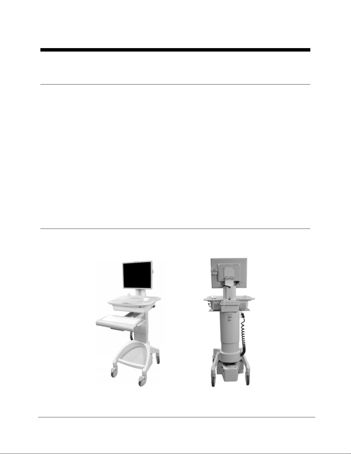
MetroTM 1800 Series Mobile Workstation Overview
The rendered image below shows the major components that comprise a MetroTM 1800 Series
Mobile Workstation.
Active Matrix
Display
Ke
Tray
Writing
Surface
board
Base Deck
Casters
Fuel Gauge
Height Adjust
Handle
Power
Supply
Antenna
Technology
Bay
AC Power
Cord
MetroTM 1800 Series Mobile Workstation
10
InterMetro Industries Corporation
Metro
TM
1800 Series Mobile Workstation Operations Manual
Page 11

Features
The MetroTM 1800 Series Mobile Workstation features:
• Rugged, steel/aluminum construction – built to last.
• Multiple DC and AC power supply options with remote fuel gauge at the user’s eye level.
Available power supply rechargeable battery technologies are Sealed Lead Acid (SLA),
Nickel Metal Hydride (NiMH), and Lithium Ion Nano-Phosphate (Li-Nano). Higher power
AC inverter available for supplying higher equipment loads.
• Several computer options:
o Notebook computers
o Low power thick client computers
o Thin clients
• Fully integrated 2.4 GHz radio with antenna; optional dual band 2.4 and 5.0 GHz radio
with antenna.
• Active LCD Display, typically single with high definition or dual display optional.
• Full size keyboard and mouse.
• Optional bar code scanner connected to USB or PS/2 ports.
• Large work surface and a full range, 13-inch pneumatic height adjustment.
• Storage options such as basket or locking storage cabinet.
• Provisions for optional auxiliary equipments: mount for video camera, shelving for
codec’s, separately powered fetal monitor etc.
• User manuals of workstation, power supply and employed equipment (Computer,
display, etc.) included.
Equipment Classification
The Metro
and mechanical hazards only in accordance with UL 60601-1 and CAN/CSA 22.2 No. 601.1 as
Type B Patient Care Medical Equipment suitable for use in patient vicinities.
The Mobile Workstation is Class I Equipment that is also internally powered.
According to the degree of protection against electric shock, the Mobile Workstation is a Type B
applied part.
According to the degree of protection against ingress of water, the Mobile Workstation is
considered ordinary.
TM
1800 Series Mobile Workstation is CSA certified with respect to electric shock, fire
MetroTM 1800 Series Mobile Workstation Operations Manual, L01-503
InterMetro Industries Corporation
11
Page 12

Warning: Risk of Explosion
TM
The Metro
for use in the presence of a flammable anesthetic mixture with air or with oxygen or
1800 Series Mobile Workstation and the Power Supply are not suitable
nitrous oxide.
The Mobile Workstation is suitable for continuous operation.
Important Product Notices
The MetroTM 1800 Series Mobile Workstation is only CSA certified if the equipment is left in its
original configuration as shipped from InterMetro Industries Corporation. If the user alters the
Mobile Workstation by changing components on, adding components to, or deleting
components from the workstation, this will void the CSA certification of the Mobile Workstation
and is expressly prohibited by InterMetro Industries Corporation.
The Power Supply used with the Metro
TM
1800 Series Mobile Workstation is provided with a
“Hospital Grade” or “Hospital Only” attachment plug for connection to the AC supply circuit.
TM
To ensure equipment grounding reliability, the Power Supply used with the Metro
1800 Series
Mobile Workstation should only be connected to AC outlet receptacles, which are marked
“Hospital Grade” or “Hospital Only”. Where the integrity of the external protective earth
connector arrangement is in doubt, equipment shall be operated from its internal electrical
power source.
Disposal
Aluminum and steel sections of the cart can be disposed of or recycled.
Electronic components or printed circuit boards, etc., shall be disposed of in accordance with
local, state and federal regulations.
Please refer to the respective supplemental operations manual included with the Mobile
Workstation for the Power Supply installed for details for disposal of the Power Supply and its
batteries used with the Metro
Sealed Lead Acid Battery:
TM
1800 Series Mobile Workstation.
The SLA Power Supply contains a sealed lead acid battery. This
battery must be recycled. Disposal of this battery must be in
accordance with local, state, and federal regulations. In Canada,
disposal must be in compliance with Canadian environmental protection
laws.
For further information call InterMetro Customer Service.
12
InterMetro Industries Corporation
Metro
TM
1800 Series Mobile Workstation Operations Manual
Page 13

Getting Started
Unpacking
The MetroTM 1800 Series Mobile Workstation will arrive fully assembled and fully functional at
the customer’s site in a cardboard box. After cutting the strapping bands, lift the top of the box
over the Mobile Workstation. In order to avoid any injury, two (2) people shall lift the Mobile
Workstation from the padding blocks. The workstation may weigh between 115 and 150 lbs
depending on the configuration.
Inspection
After the MetroTM 1800 Series Mobile Workstation has been unpacked, the user should inspect
the unit for any shipping damage. If there is any damage, please contact InterMetro Customer
Service immediately.
Power Supply Preparation
Before placing a MetroTM 1800 Series Mobile Workstation into service, the Power Supply battery
may need to be connected and should be initially charged for a full 24 hours.
Important Notice:
Please refer to the respective supplemental operations manual included with the Mobile
Workstation for the Power Supply installed for requirements and details on battery preparation
and initial charging of the Power Supply.
To charge the battery:
• For DC output power supplies, plug the coiled AC power cord into an AC outlet and put
the “ON/Extended Storage Switch” into the "ON" position (see "Turning on the Power
Supply" below).
• For AC Inverter power supplies, plug the coiled AC power cord into an AC outlet only. It
is not necessary to turn on the supply.
Notice: For further information on power supply charge times and on the charge indicator
lights of the Remote Fuel Gauge, please refer to the respective Power Supply
supplement.
MetroTM 1800 Series Mobile Workstation Operations Manual, L01-503
InterMetro Industries Corporation
13
Page 14

Turning on the Power Supply
Turning on the DC Output Power Supply
If so equipped, the DC Output Power Supply of the Metro
TM
1800 Series Mobile Computing
Workstation must be turned on to power all the workstation equipment. The Power Supply is
controlled by the “ON/Extended Storage” Switch located on the Power Supply that is typically
mounted on the bottom of the workstation.
TM
ON/Extended
Storage Switch
In the “ON” position, the power supply provides power to the Metro
Series Mobile Computing Workstation systems. If the workstation is not
1800
used for an extended period of time, the ON/Extended Storage Switch
should be put in the “Extended Storage” (OFF) position. The switch
position disconnects the battery from any internal or external equipment
and avoids deep discharges of the battery, which can cause damage to
the battery.
Important Notice:
Please refer to the respective supplemental operations manual included
with the Mobile Computing Workstation for the Power Supply installed for
further details of the “ON/Extended Storage” Switch and the requirements
for long term (more than one week) storage.
NiMH MPE-7800
Li-Nano MPS-4007/NiMH MPS-4008
14
InterMetro Industries Corporation
Example Locations of ON/Extended Storage Switch
TM
Metro
1800 Series Mobile Workstation Operations Manual
SLA MPS-3111
Page 15

Warning: Risk of Electric Shock
The power supply employs a battery to provide mobile DC output power.
Low voltage (10-16 VDC) DC power is available from the power supply
even when the AC cord is disconnected from an AC outlet. Please refer
to the respective supplemental operations manual included with the
Mobile Computing Workstation for the Power Supply installed for the
proper way to completely remove DC power.
Turning on the AC Inverter Power Supply
If so equipped, the AC Inverter Power Supply of the Metro
TM
1800 Series Mobile Computing
Workstation must be turned on to power all the workstation equipment. The Power Supply is
controlled by the “ON/OFF” Switch located on the Remote Fuel Gauge that is located on the
display stalk of the workstation.
AC Inverter
Power Supply
ON/OFF Switch
Press and hold the ON/OFF switch on Remote Fuel Gauge for 2 seconds
to toggle the power supply AC Output ON. The LEDs will come on to
indicate the AC Output is on as well as charge level of the battery.
Important Notice:
Please refer to the respective supplemental operations manual included
with the Mobile Computing Workstation for the Power Supply installed for
further details of the “ON/OFF” Switch and the requirements for long term
(more than one week) storage.
ON/OFF
Location of ON/OFF Switch
Warning: Risk of Electric Shock
The power supply employs a battery to provide mobile AC output power.
High voltage and current AC voltage (120 or 230 VAC nominal) power is
available from the power supply, even AC cord is disconnected from an
AC outlet. Please refer to the respective supplemental operations manual
included with the Mobile Computing Workstation for the Power Supply
installed for the proper way to completely remove inverted AC power.
MetroTM 1800 Series Mobile Workstation Operations Manual, L01-503
InterMetro Industries Corporation
15
Page 16

Powering up the Computer Equipment
Powering up the
computer
equipment
Powering up the
display
You can power up the Mobile Workstation during the initial charge. The
equipment has been designed to operate while mobile or when plugged
into an AC outlet.
Power
Switch
Example Location of Computer Power Switch
The ON/OFF switch for the computer is located in the front underneath
the writing surface. Depending on your computer configuration, the
switch may be on the left, middle or right side.
Depress the power switch on the display to turn on the display. The
display can be left on at all times, because a power saving mode shuts
down the display when no video signal is present.
Starting Windows and Wireless Network
The computer starts with a Windows operating system preinstalled.
Depending on the configuration, you may have a standard installation
or a custom installation for your location that may require you to enter
Windows authorization codes. All codes along with a Windows
installation CD are shipped with the Mobile Workstation. For setting-up
the wireless LAN and connecting to the hospital network, consult your
IT department.
16
InterMetro Industries Corporation
Metro
TM
1800 Series Mobile Workstation Operations Manual
Page 17

Operation
Description of Major Components
Depending on your order, your MetroTM 1800 Series Mobile Workstation will be delivered in a
specific configuration. The configuration will employ each of the following components:
• The Metro
steel and aluminum with a pneumatic lift and employs a large work surface.
• Power Supplies
• AC to DC power supply with charger and one of the following types of battery
technologies:
• AC Output Inverter power supply with charger and Sealed Lead Acid batteries, primarily
for higher power requirements and portable applications.
• Remote Fuel Gauge
• Optional Mobile Workstation Power Supply Management Software
• Computers
• Notebooks
• Low power thick clients
• Thin clients
• Wireless PC Card
• Display
• Active LCD Display, typically single with high definition or dual displays optional.
• Optional adjustable up/down mount
• Mouse
• Any UL certified optical or ball, PS/2 or USB mouse
• Keyboard
• Any UL certified PS/2 or USB keyboard
• Optional tilting keyboard tray
• Optional Barcode Scanner
• CCD USB Scanner
• Approved laser scanner
• Optional Storage
• Basket - Front or rear mounting
• Storage cabinet with optional mechanical or electronic locking.
• Provisions for optional auxiliary equipment
• Video camera with mount
• Shelving for codec’s, separately powered fetal monitor, etc.
TM
1800 Base is common among all the different configurations. It is made of
o Sealed Lead Acid (SLA)
o Nickel Metal Hydride (NiMH)
o Lithium Iron Nano Phosphate (Li-Nano)
MetroTM 1800 Series Mobile Workstation Operations Manual, L01-503
InterMetro Industries Corporation
17
Page 18

MetroTM 1800 Base
y
The MetroTM 1800 Base is the backbone of every MetroTM 1800 Series Mobile Workstation.
Ke
board
Tray
Antenna
Base Deck
Casters
Writing
Surface
Metro
TM
1800 Series Base (Shown with Single Display)
The Base features casters to wheel it around easily, provides mounting hardware to mount the
power supply, and offers a foot rest to the user, storage space in different options, a large
writing/working surface, technology tray for the computer equipment, keyboard tray and
mounting stalk for the display as well as a pneumatic 13-inch lift to adjust the height. These
features are explained in detail in the following pages.
18
InterMetro Industries Corporation
Metro
TM
1800 Series Mobile Workstation Operations Manual
Page 19

Writing Surface
The Metro
TM
1800 Base has a large writing surface. In addition to using it as a writing surface, it
allows you to easily navigate Windows and your applications using the attached mouse.
Writing Surface
The writing surface is designed so that it may be easily gripped on the edge all the way around.
The edge grip is used when you need to raise or lower the workstation. The easy to grip edge
and a handle at the front of the writing surface allow you to easily grip and maneuver the
TM
Metro
1800 Series Mobile Workstation in and around a patient’s room or through hospital
corridors.
Caution
Only use the edge gripping when raising or lowering the writing surface and rolling
the Mobile Workstation around. Never attempt to physically lift the
TM
Metro
1800 Series Mobile Workstation off the ground by pulling on the edge grip or
any other part of the writing surface. If you need to lift a Metro
TM
1800 Series Mobile
Workstation off the ground, pick it up at the wheelbase. Generally, this task requires
two (2) people.
MetroTM 1800 Series Mobile Workstation Operations Manual, L01-503
InterMetro Industries Corporation
19
Page 20

Height Adjustment
The height adjustment handle is used to adjust the height of the Metro
TM
1800 Series Mobile
Workstation. The writing surface height can be set within a 13-inch dynamic range of
adjustment, making it easier to type and read the display from either a standing or sitting
position.
Height Adjustment Handle
Raising the
TM
Metro
1800
Series Mobile
Workstation’s
Writing Surface
Perform the following steps to raise the writing/work surface of the
TM
Metro
1800 Series Mobile Workstation using the height adjustment
handle:
• Stand in front of the workstation and grasp the height adjustment
handle with your right hand.
• Grab the left side of the writing surface with your left hand.
• Pull the height adjustment handle up.
• While holding the height adjustment handle up, lift the writing
surface to the desired height and then release the height
adjustment handle.
20
InterMetro Industries Corporation
Metro
TM
1800 Series Mobile Workstation Operations Manual
Page 21

MetroTM 1800 Cart at the Highest Position
Lowering the
TM
Metro
1800
Series Mobile
Workstation’s
Writing Surface
Perform the following steps to lower the writing/work surface of the
TM
Metro
1800 Series Mobile Workstation using the height adjustment
handle:
• Stand in front of the workstation and grasp the height adjustment
handle with your right hand.
• Grab the left side of the writing surface with your left hand.
• Pull the height adjustment handle up.
• While holding the height adjustment handle up, push the writing
surface down to the desired height and then release the height
adjustment handle.
TM
Metro
1800 Cart in the Lowest Position
MetroTM 1800 Series Mobile Workstation Operations Manual, L01-503
InterMetro Industries Corporation
21
Page 22

Keyboard Tray
The keyboard tray is located directly underneath the technology bay. It is designed to lock into
place when it is fully extended (an extra tug may be required to lock it into place) and to lock into
place when it is recessed all the way back in under the technology bay (an extra push may be
required to lock it into place). This prevents the keyboard tray from moving around while the
user is typing or moving the Mobile Workstation.
Keyboard Tray
The keyboard is securely attached to the tray using Velcro. The keyboard is typically covered
by a clear, non-latex, rubberized membrane that protects the keyboard from liquid spills and
splatters. It can be easily cleaned using a hospital-safe disinfectant. It can also be removed
and replaced with a new membrane. New membranes can be ordered from InterMetro
Customer Service.
Caution:
Use caution when moving the keyboard tray to avoid trapping fingers between the
keyboard and the workstation base.
22
InterMetro Industries Corporation
Metro
TM
1800 Series Mobile Workstation Operations Manual
Page 23

Tilting Keyboard Tray Option
The Metro
TM
1800 Series Mobile Workstation can be deployed with an optional tilting keyboard
tray for ergonomic comfort.
Tilting Keyboard Tray
When the tray is fully extended, it can be adjusted by lifting the front edge until a click is heard,
indicating the first and lowest tilt position, and then releasing it. The tray can be adjusted to one
of three tilt positions.
To lower the tray to the original bottom horizontal (untilted) position, lift the tray all the way up
and drop it back to the bottom position while holding the front edge of the tray.
Lifting Tilting Keyboard Tray to Adjust Position
Caution:
Do not push the keyboard tray in while it is in a tilted position. Lift the tray all the way
up and drop it back to the bottom position while holding the front edge of the tray
before pushing it in.
MetroTM 1800 Series Mobile Workstation Operations Manual, L01-503
InterMetro Industries Corporation
23
Page 24

Storage Options
The Metro
TM
1800 Series Mobile Workstation can be deployed with storage designed to carry
documents, accessories or supplies needed by a nurse or doctor.
The basket is very sturdy and can hold virtually anything up to a maximum weight of 10 lbs.
The additional weight will, however, make adjusting the workstation height more difficult. A
variety of baskets can be mounted at the front or rear of Metro
TM
1800 cart.
Metro 1800 Basket Option Mounted on Back of Cart
The storage bin can be deployed in one, two or three drawer versions. The storage bin can be
configured to be locked with a TouchPoint™ pin cipher lock or with an ELC 100 Electric
Latching Cabinet system. The ELC 100 storage bin can be unlocked through the workstation
computer or optional stand alone credentialing device, such as a keypad. The storage bin can
hold anything up to a maximum total weight of 10 lbs. The additional weight will, however,
make adjusting the Mobile Workstation height more difficult.
Metro 1800 Two-Drawer Storage Bin with Pin Cipher Lock option
24
InterMetro Industries Corporation
Metro
TM
1800 Series Mobile Workstation Operations Manual
Page 25

Auxiliary Equipment Support
TM
The Metro
1800 Series Mobile Workstation has provisions and optional high capacity Power
Supply to support additional options and auxiliary equipment:
• Video camera:
A mount and cabling can be provided for a camera for video conferencing and telemedicine.
The camera is usually mounted above the monitor(s) in an operational system.
Video Camera Mounted above Display
• Shelf for heavy equipment for portable operation:
An optional auxiliary shelf is available to hold heavy equipment such as a codec (used for video
conferencing and telemedicine) or to transport separately powered heavy equipment such as a
Fetal Monitor.
Codec in Auxiliary Shelf Metro 1800 Series showing “Fetal
Monitor”
Notice: The Fetal Monitor is a separate piece of equipment transported by the properly
equipped 1800 Series Mobile Workstation and shall not be connected to or powered
by the Workstation Power Supply. The Fetal Monitor shall be plugged into a
separate properly rated wall outlet by its own AC cord.
MetroTM 1800 Series Mobile Workstation Operations Manual, L01-503
InterMetro Industries Corporation
25
Page 26

Foot Rest Base
The base deck of the Metro
TM
1800 Series Mobile Workstation is designed to be used as a
footrest while either standing or sitting. Placing your feet on the deck will not cause any
problems with the power supply.
Casters
The Metro
TM
1800 Series Mobile Workstation is configured with two locking and two non-locking
casters. The two locking casters are on the front of the workstation.
Lock
Unlock
To lock a caster in the front, press its locking tab down.
To unlock a caster, lift its locking tab up.
TM
Metro
1800 Base Casters
26
InterMetro Industries Corporation
Metro
TM
1800 Series Mobile Workstation Operations Manual
Page 27

Flat Panel Display
The MetroTM 1800 Series Mobile Workstation comes typically with an LCD display. The standard
display is capable of displaying screen resolutions of up to 1280x1024 pixels. Optionally, the
TM
Metro
landscape or portrait.
In order to avoid damaging the display’s screen, do not press the screen with your fingers. A
soft, clean, lint-free cloth or a lens brush of camel hair should be used to clean the screen.
Never pour or spray any type of liquid onto the display.
Additional information about the operation of the display can be found in the operating manual
from the original manufacturer provided with the Mobile Workstation. For additional information,
please contact InterMetro Customer Service.
1800 may come with a larger display or in a dual display configuration in either
Powering Up the
Display
Adjusting Display
Parameters
The Metro
TM
1800 Series Mobile Workstation power supply must be
turned ON first before turning ON the display. The ON/OFF switch for the
display is located on the display and may be turned ON/OFF as required.
To adjust different parameters on the display like brightness, contrast,
color, etc., please refer to the display’s user manual, which is shipped with
the Mobile Workstation.
Notice: In order to increase the run-time of your Metro
TM
1800 Series
Mobile Workstation with one charge of the power supply battery,
the display’s brightness should not be set higher than 15%.
Depending on the make of display, it is factory set from
0 to 15%. If, for any reason, the brightness is set to a higher
value, set it back to less than 15% for an increased run-time.
Flat Panel Display
MetroTM 1800 Series Mobile Workstation Operations Manual, L01-503
InterMetro Industries Corporation
27
Page 28

Adjusting the
Display Position
To adjust the display position to tilt up or down, grab the top and bottom in
each hand and move the top forward or back to the position desired.
Display Tilted Up
28
InterMetro Industries Corporation
Metro
TM
1800 Series Mobile Workstation Operations Manual
Page 29

Computer
The MetroTM 1800 Series Mobile Workstation currently employs the following array of
computers:
• Notebooks
• Low power thick clients
• Thin clients
The computer comes either with a Windows operating system preinstalled, or bears a custom
image for your location. On some configurations, it may be necessary to enter the Windows
licensing keys. The keys and a Windows installation CD are shipped with the cart. The thin
clients feature Windows XP Embedded.
For additional information about the operation of the computer and operating system, see the
operating manuals from the original manufacturers provided with the Mobile Workstation.
The computer is installed in the technology bay of your Metro
TM
1800 Series Mobile
Workstation. In addition to the computer, the technology bay houses all the necessary cabling
for display, mouse, keyboard, power conditioning to power the computer hardware and optional
equipment, like barcode scanners or ELC-100 Electric Latching Cabinet.
Computer in Technology Bay
MetroTM 1800 Series Mobile Workstation Operations Manual, L01-503
InterMetro Industries Corporation
29
Page 30

Powering up the computer
The power button of the computer is normally located in the front of the Mobile Workstation on
the technology bay level under the work surface.
In older models of the Metro
TM
1800 Series Mobile Workstation, the technology bay is located
behind the keyboard tray and vertically against the column. Power switch is on the right side
next to the column on the side of the technology bay.
Power Switch –
Located at front
of cart
Power Switch – When
computer located
behind keyboard tray
Example Locations of Power Button
In order to power up the computer, press the power button for less than one second and the
computer will boot up. If the display stays black, make sure that the display has been turned
ON (see “Powering Up the Display” under the “Flat Panel Display” section above).
Turning off the computer
The computer is typically shut down with the Windows’ shutdown feature. To perform a
hardware shut down of the computer, depress the power button for at least 4 seconds.
Troubleshooting computer problems
If the computer equipment does not function properly, please refer first to the computer
manufacturer’s user manual, which is shipped with the Mobile Workstation.
If your problem is not addressed in the computer’s user manual, please consult your IT
department. If the IT department determines a hardware defect, please contact InterMetro
Customer Service.
30
InterMetro Industries Corporation
Metro
TM
1800 Series Mobile Workstation Operations Manual
Page 31

Power Supply
Your MetroTM 1800 Series Mobile Workstation may be equipped with a DC Power Supply
providing a DC voltage output with one of the following battery technologies: Nickel Metal
Hydride (NiMH), Lithium Ion Nano Phosphate (Li-Nano or LiFePO
Alternately the Metro
TM
1800 may be equipped with an AC Inverter with SLA batteries,
especially to supply portable AC power to a high power equipment load.
Notice: The preparation and operation of the Power Supply are detailed in the respective
supplemental operations manual included with the Mobile Workstation for the Power
Supply installed.
The Power Supply is designed for continuous operation and service is not interrupted by
plugging in or unplugging the Power Supply.
) or Sealed Lead Acid (SLA).
4
Powering Up the DC Power Supply
The DC Power Supply is controlled by the “ON/Extended Storage” Switch located on the Power
Supply that is typically mounted on the bottom of the Mobile Computing Workstation.
• In the “ON” position, the power supply provides DC voltage power to the Metro
TM
1800
Series Mobile Computing Workstation systems. In the “Extended Storage” position,
power is removed from the workstation equipment.
NiMH MPE-7800
SLA MPS-3111
Li-Nano MPS-4007/ NiMH MPS-4008
Example Locations of ON/Extended Storage Switch
MetroTM 1800 Series Mobile Workstation Operations Manual, L01-503
InterMetro Industries Corporation
31
Page 32

Powering Up the AC Inverter Power Supply
The AC Inverter Power Supply is controlled by the “ON/OFF” Switch located on the Remote
Fuel Gauge that is located on the display stalk of the workstation.
TM
• In the “ON” position, the power supply provides AC voltage power to the Metro
1800
Series Mobile Computing Workstation systems. In the “OFF” position, power is removed
from the workstation equipment.
• Press and hold the ON/OFF switch on Remote Fuel Gauge for at least 2 seconds to
toggle the power supply AC Output from “OFF” to “ON”, or from “ON” to “OFF”. The
LEDs will come on to indicate that the AC Output is on as well as show the charge level
of the battery.
ON/OFF
Location of ON/OFF Switch
Extended Storage
If the Mobile Workstation is not used for an extended period of time, the power to the
workstation equipment should be removed to disconnect the battery from any internal or
external equipment and to avoid deep discharges of and possible damage to the battery that
would occur if the Power Supply is left on.
• For the DC Power Supply: The ON/Extended Storage Switch should be put in the
“Extended Storage” (OFF) position.
• For the AC Inverter Power Supply: Press and hold the ON/OFF switch on Remote Fuel
Gauge for at least 2 seconds to toggle the power supply AC Output from “ON” to “OFF”
and ensure all the LEDs turn off.
Notice: Long Term Storage (Longer than one week)
If the Mobile Workstation is to be placed in long term storage (longer than one week), the Power
Supply should be fully charged before removing workstation equipment power per the
procedure above for Extended Storage.
32
InterMetro Industries Corporation
Metro
TM
1800 Series Mobile Workstation Operations Manual
Page 33

Important Notice: DC Power Supply
Please refer to the respective supplemental operations manual included with the
Mobile Computing Workstation for the DC Power Supply installed for further details of
the “ON/Extended Storage” Switch and the requirements for long term (more than
one week) storage.
Important Notice: AC Inverter Power Supply
Please refer to the respective supplemental operations manual included with the
Mobile Computing Workstation for the AC Inverter Power Supply installed for further
details of the Fuel Gauge “ON/OFF” Switch and the requirements for long term (more
than one week) storage.
Remote Fuel Gauge
To monitor the charge level of the Power Supply battery cells when operating on mobile power,
a Remote Fuel Gauge is connected to the power supply. The embedded Remote Fuel Gauge is
located just below the display in the stalk and gives the user the current battery status at eye
level height.
Remote Fuel Gauge
The LED’s of the Remote Fuel Gauge will always display the battery’s charge level whether the
computer is operating or not.
Notice: The functions of the Remote Fuel Gauge are detailed in the respective supplemental
operations manual included with the workstation for the Power Supply installed.
MetroTM 1800 Series Mobile Workstation Operations Manual, L01-503
InterMetro Industries Corporation
33
Page 34

Maintenance
Cleaning
Use 70 percent isopropyl alcohol (IPA) diluted with water for cleaning. You may also use one of
these products:
• Cidex
• Clorox Clean-Up
• “Green soap” United States Pharmacopoeia (USP)
• Formula 409
• Sani-Cloth. Plus
• Virustat TBQ
Ensure that the workstation is off and unplugged. Apply 70 percent isopropyl alcohol to a clean
nonabrasive cloth and then wipe all surfaces of the workstation. Cleaners applied close or
directly to openings (e.g. ventilation slots) could leak inside and cause damage. Be careful not
to splash solvents on the power supply enclosure.
Adjustments and Tightening
Periodic checks should be performed for tightness of fasteners and screws. For additional
details, please contact InterMetro Customer Service.
Power Supply Batteries
Power Supply Batteries have a charge cycle lifetime based on technology and may need
periodic replacement. Please refer to the respective supplemental operations manual included
with the Mobile Workstation for the Power Supply installed for details of battery replacement for
the Power Supply or contact InterMetro Customer Service.
Power Supplies using Lithium-Ion type batteries are subject to special shipping conditions and
are not connected during shipment due to USDOT and IATA regulations. Please refer to the
respective supplemental operations manual included with the Mobile Workstation for the Power
Supply installed for requirements and details on battery preparation for the Power Supply.
Power Supply Air Filter
Power supplies equipped with an air filter require periodic maintenance. Please refer to the
respective supplemental operations manual included with the Mobile Workstation for the Power
Supply installed for requirements and details of periodic air filter cleaning and replacement.
34
InterMetro Industries Corporation
Metro
TM
1800 Series Mobile Workstation Operations Manual
Page 35

Power Supply Fuse Replacement
Please refer to the respective supplemental operations manual included with the Mobile
Workstation for the Power Supply installed for requirements and details of Power Supply fuse
replacement.
Caution:
For continued protection against risk of fire, replace only with the same type and
rating of fuse.
Storage and Transport Conditions
Environmental conditions for shipping and storage are:
• Ambient temperature range of -40 °C to +70 °C (-40 °F to 160 °F).
• Relative humidity range of 10% to 100%.
• Atmospheric pressure range of 14.76 in. Hg to 31.29 in. Hg.
Special shipping conditions for Lithium-Ion Batteries:
Caution:
The following applies to Power Supplies using Lithium-Ion type batteries only:
In accordance with USDOT and IATA regulations, the Lithium-Ion cells shall not be
shipped or transported in another vehicle on public roads with the Lithium-Ion cells or
battery packs connected. Please refer to the respective supplemental operations
manual included with the Mobile Workstation for the Power Supply installed for
requirements and details on battery preparation for the Power Supply.
MetroTM 1800 Series Mobile Workstation Operations Manual, L01-503
InterMetro Industries Corporation
35
Page 36

Power Savings
In order to conserve power and enjoy a long run-time with a single battery charge, several
parameters need to be set on the workstation computer and display.
Computer Settings
Two parameters need to be set on the workstation computer:
1. Turn OFF any computer screen saver. Some screen savers require a high amount of
computational power and cause high power consumption.
2. Through the Windows Control Panel, open the Power Options Properties and set it to the
following:
Power Options Properties Control Panel
Caution:
Under no circumstances should the computer “Power schemes” be set to “Always
On”: the setting significantly reduces power supply run time on batteries and may
cause the computer equipment to overheat.
Flat Panel Display Settings
The Flat Panel Display brightness should not be set higher than 15%. To adjust the brightness
parameter of the display, please refer to the display’s user manual, which is shipped with the
Mobile Workstation. See “Adjusting Display Parameters” in “Flat Panel Display” section above.
36
InterMetro Industries Corporation
Metro
TM
1800 Series Mobile Workstation Operations Manual
Page 37

Troubleshooting
Use the tips in this section as a guide. They include solutions to the simplest problems as well
as things to observe when trying to diagnose problems.
Consider the following:
• If a problem occurs while you're working, stop immediately. If you continue, you may
lose data and destroy problem-related information.
• Observe what is happening. Write down what the computer and any optional devices
are doing as well as what actions you took immediately before the problem occurred.
• Is the computer running? Are the cables properly attached to the back of the power
supply?
• Which part of the system is operating erratically? Keyboard? Disk/Flash Drive? Radio?
Display? Power Supply? Each produces different symptoms.
• What program and/or optional devices are you using?
• What appears on the screen? Do you see any messages or random characters? Look
up any messages in the documentation for your software.
• Are any LEDs illuminated? Which ones on which devices?
• Do you hear any beeps? How many? Are they long or short?
• Is the computer making any unusual noises?
• Are the locking wheels locked or unlocked?
• Are the fuses in the power supply intact?
• See if you can cause the problem to occur again. This may help you understand the
source of the problem and will help you describe the problem if you must call InterMetro
Customer Service for technical assistance.
Additional troubleshooting details are also provided in the Power Supply Operations Manual
Supplement for the Power Supply and may be included in other manuals for equipment and
software applications included with the workstation.
MetroTM 1800 Series Mobile Workstation Operations Manual, L01-503
InterMetro Industries Corporation
37
Page 38

Technical Specifications
MetroTM 1800 Series Cart - Model 1800 Overall Cart
Work Surface Height Adjustable from 32" to 45"
Overall Height 51" to 61" (depending on adjustment)
Work Surface Dimensions 21" x 21"
Maximum Work Surface
5 lbs.
Load
Weight 115 to 130 lbs. (depending on configuration)
Base Dimensions 19" x 22"
Construction Steel/Aluminum
Finish Industrial powder coat
Wheels 4 swivel (2 locking, 2 non-locking)
Input Voltage 100-240 VAC, 50/60 Hz, 5.0 A max
Battery Technology NiMH or Li-Ion Nano Phosphate or Sealed Lead Acid (please
see applicable Power Supply supplement)
Computer Various types of thin client, thick client and notebook computers
Communication Wireless LAN, IEEE802.11a/b/g/n
Display Various types of flat panel display
Approvals FCC Part 15 Subpart B, Class A, Industry Canada Class A
UL60601-1 and CSA C22.2 No. 601.1
Select models carry the following additional approvals:
IEC/EN 60601-1-1 (Safety, Medical Equipment)
IEC/EN 60601-1-2 (EMC, Medical Equipment)
RoHS compliant (RoHS Directive 2002/95/EC)
38
InterMetro Industries Corporation
Metro
TM
1800 Series Mobile Workstation Operations Manual
Page 39

MetroTM 1800 Series Cart – Model 1860 Overall Cart
Work Surface Height Adjustable from 35" to 48"
Overall Height 54" to 67" (depending on adjustment)
Work Surface Dimensions 22" x 18"
Maximum Work Surface
5 lbs.
Load
Weight 120 to 150 lbs. (depending on configuration)
Base Dimensions 19" x 22"
Construction Steel/Aluminum
Finish Industrial powder coat
Wheels 4 swivel (2 locking, 2 non-locking)
Input Voltage 100-240 VAC, 50/60 Hz, 5.1 A max
Battery Technology NiMH or Li-Ion Nano Phosphate or Sealed Lead Acid (please
see applicable Power Supply supplement)
Computer Various types of thin client, thick client and notebook computers
Communication Wireless LAN, IEEE802.11a/b/g/n
Display Various types of flat panel display
Approvals FCC Part 15 Subpart B, Class A, Industry Canada Class A
UL60601-1 and CSA C22.2 No. 601.1
Select models carry the following additional approvals:
IEC/EN 60601-1-1 (Safety, Medical Equipment)
IEC/EN 60601-1-2 (EMC, Medical Equipment)
RoHS compliant (RoHS Directive 2002/95/EC)
Power Supply
For Power Supply, please refer to the Power Supply Operations Manual Supplement that is
supplied with your Metro
TM
1800 Series Mobile Workstation.
Computer Equipment
For computer equipment, like computer, display, mouse, keyboard, etc. please refer to the
equipments’ user manuals, which are supplied with your MetroTM 1800 Series Mobile
Workstation.
MetroTM 1800 Series Mobile Workstation Operations Manual, L01-503
InterMetro Industries Corporation
39
Page 40

Contacting InterMetro Industries Corporation
InterMetro Industries Corporation Contact Information
InterMetro Industries Corporation
651 North Washington Street
Wilkes-Barre, PA 18705
Phone: 1-800-992-1776
http://www.metro.com/support
InterMetro Customer Service
For all customer service related issues, or if you need technical
assistance, please call our customer service department at:
1-800-992-1776 Americas
905 676 9890 Canada
+31 76 58 77550 Europe
+9714 811 8286 Middle East
+65 6567 8003 Asia-Pacific
Repair
To return equipment for repair:
• Have model and serial numbers ready: obtain the Workstation
information from its label as shown at left.
• Contact InterMetro Customer Service at the contact number
given above to obtain a RMA number.
• Please write the RMA number on the air bill in the reference
section and the outside of the package.
• Return the equipment to:
InterMetro Mexico (Acuna)
TRA – InterMetro
C/o Fernando Castillon
40
InterMetro Industries Corporation
Metro
TM
1800 Series Mobile Workstation Operations Manual
100 Lupita Circle
Del Rio, TX 78840
 Loading...