

Page 1
ULN-R Mic Pre Installation
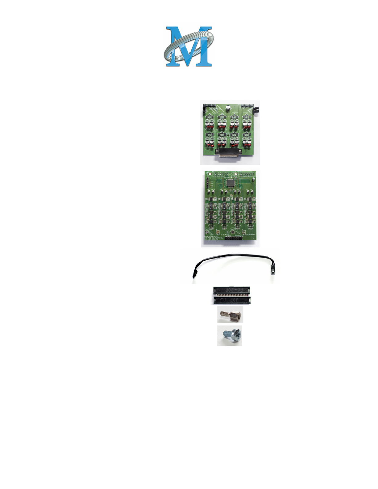
The ULN-R Mic Pre (Ch. 1-4) kit includes the following parts:
1 DB25 connector board
1 4 channel ULN-R mic pre board
1 3 pin phantom power cable
1 20 pin ribbon cable jumper
2 7/16” standoffs
3 Phillips head screws
The ULN-R Mic Pre (Ch. 5-8) kit includes the following parts:
1 4 channel ULN-R mic pre board
1 20 pin ribbon cable jumper
4 Phillips head screws
The Ch. 1-4 kit must be installed for the Ch 5-8 kit to function!
To install the ULN-R mic pre option in the LIO-8 you will need:
- #1 Phillips screwdriver
- 7/16” nutdriver (Ch. 1-4 kit only)
- silicone caulk
Please familiarize yourself with the parts and instructions before opening the LIO-8.
Be sure to discharge any static energy on your body before touching the interior of the LIO-8.
Page 2
Installing the mic pres:
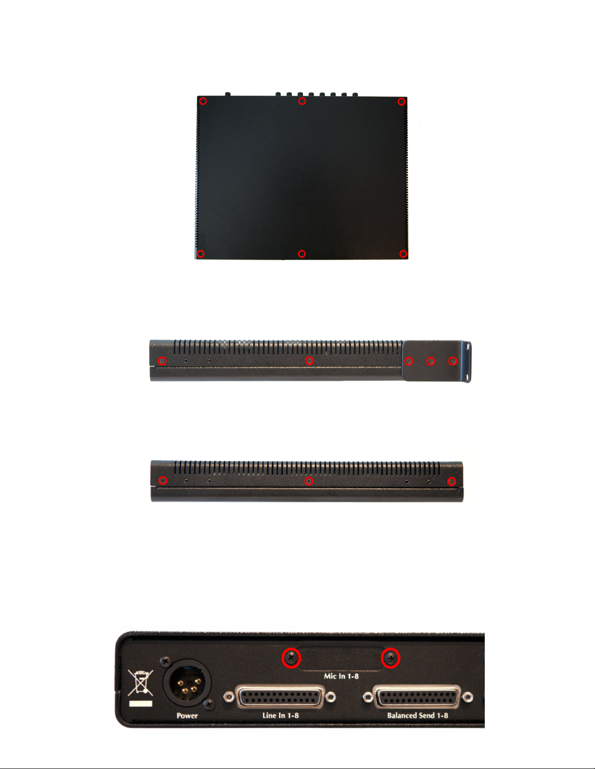
1) Remove the six screws from the top of the case:
2) Remove the screws from the left and right sides of the case. If the rack ears are tted, there will be ve
screws per side. Please note that the screws on the rack ears are longer than the others. Be sure to put
the longer screws back in the rack ears when you reassemble the LIO-8.
If the rack ears are not tted, there will be three screws per side.
Remove the top cover, and rotate the unit so that the rear panel is facing you. If you are installing the
Ch. 5-8 kit only, jump to step 9.
3) Remove the two screws holding the Mic In cover plate, then remove the plate from inside the LIO-8.
Page 3

4) Put the DB25 connector board into the LIO-8 so that the connector comes through the hole that you
just uncovered. Put the two 7/16” standoffs through the rear panel and screw them into the DB25 connector.
5) Use a Phillips head screw to secure the connector board to the standoff below it and put a dab of
silicone caulk on the screw to hold it in place. Next, make sure that connector J5 is bent out at a slight
angle; this is to ensure that the phantom power cable will clear the top cover.
6) Remove the jumpers from J8 and J9 on the power supply board at the front of the LIO:
Page 4

7) Connect the phantom power cable between connector J5 on the DB25 connector board to connector
J5 on the power supply board at the front of the LIO:
8) Install the mic pre board, making sure that the pins on the bottom of the board line up with the
sockets highlighted in the picture above. You must install the channel 1-4 board in this position. Use
two Phillips head screws to secure the mic pre board and dab them with caulk. Fit the ribbon cable
jumper between the mic pre and DB25 connector board, making sure that the pins are lined up.
Page 5

9) If you are installing the channel 5-8 mic pre kit, install it in the sockets next to the channel 1-4 board,
making sure the pins are properly seated. Use four Phillips head screws to secure the mic pre board and
dab them with caulk. Fit the ribbon cable jumper between the mic pre and DB25 connector board, making sure that the pins are lined up.
The installation is nished! Replace the top cover, and replace the six crews on the top of the case. Then
replace the screws on the left and right side, remembering to use the longer screws on the rack ears. It
sometimes helps to squeeze the top and bottom of the case together when replacing the side screws, to
ensure that the outer holes line up with the threaded inserts.
Once you have reassembled the unit, connect it to your computer and power it up. When looking at an
Analog input in MIO Console, you will now have the “Mic” and “Mic S/R” selections as input choices,
as well as phantom power control.
If you have any questions about the installation process, contact support@mhlabs.com.
 Loading...