

Page 1

Mobile I/O
User’s Guide
Page 2

Mobile I/O Users Guide
Metric Halo
Revision: v5.6.01
Publication date Mon Aug 26 15:05:10 EDT 2013
Copyright © 2013 Metric Halo
Page 3

Table of Contents
Introduction .................................................................................................................................... 20
I. Quick Start Guides ...................................................................................................................... 21
1. 2882 Quick Start Guide ...................................................................................................... 23
Prepare the unit for use ................................................................................................... 23
Connect the 2882 ........................................................................................................... 24
Take a listen .................................................................................................................. 24
MIO Console ................................................................................................................. 24
The Console window .............................................................................................. 25
The Mixer window ................................................................................................. 26
The 2882 and surround ........................................................................................... 27
Unleash the DSP .................................................................................................... 29
Additional Resources ...................................................................................................... 29
2. ULN-2 Quick Start Guide .................................................................................................... 30
Prepare the unit for use ................................................................................................... 30
Connect the ULN-2 ........................................................................................................ 31
Take a listen .................................................................................................................. 31
MIO Console ................................................................................................................. 31
The Console window .............................................................................................. 31
The Mixer window ................................................................................................. 32
The ULN-2 and surround ........................................................................................ 33
Unleash the DSP .................................................................................................... 36
Additional Resources ..................................................................................................... 36
3. LIO-8 Quick Start Guide ..................................................................................................... 37
Prepare the unit for use ................................................................................................... 37
Connect the LIO-8 .......................................................................................................... 38
Get familiar with the front panel ...................................................................................... 38
Take a listen .................................................................................................................. 38
MIO Console ................................................................................................................. 38
The Console window .............................................................................................. 39
The Mixer window ................................................................................................. 40
The LIO-8 and surround .......................................................................................... 41
Unleash the DSP .................................................................................................... 43
Additional Resources ..................................................................................................... 43
4. ULN-8 Quick Start Guide .................................................................................................... 45
Prepare the unit for use ................................................................................................... 45
Connect the ULN-8 ........................................................................................................ 46
Get familiar with the front panel ...................................................................................... 46
Take a listen .................................................................................................................. 46
MIO Console ................................................................................................................. 46
The Console window .............................................................................................. 47
The Mixer window ................................................................................................. 48
The ULN-8 and surround ........................................................................................ 49
Unleash the DSP .................................................................................................... 51
Additional Resources ..................................................................................................... 51
II. Interfaces ................................................................................................................................... 53
5. 2882 Users Guide .............................................................................................................. 56
2882 Overview .............................................................................................................. 56
What it is ............................................................................................................... 56
What it has ............................................................................................................ 56
What you need to use it ......................................................................................... 57
What comes with it ................................................................................................ 57
3
Page 4

Mobile I/O Users Guide
Using the 2882 Hardware ............................................................................................... 58
2882 Front Panel .................................................................................................... 58
2882 Rear Panel ..................................................................................................... 59
2882 Signal Flow ................................................................................................... 60
Making connections to the 2882 .............................................................................. 60
2882 Specifications ......................................................................................................... 65
6. ULN-2 Users Guide ............................................................................................................ 69
ULN-2 Overview ............................................................................................................ 69
What it is ............................................................................................................... 69
What it has ............................................................................................................ 69
What you need to use it ......................................................................................... 70
What comes with it ................................................................................................ 70
Using the ULN-2 Hardware ............................................................................................. 71
ULN-2 Front Panel ................................................................................................. 71
ULN-2 Rear Panel .................................................................................................. 73
Signal Flow ............................................................................................................ 74
Making connections to the ULN-2 ........................................................................... 74
ULN-2 Specifications ...................................................................................................... 79
7. LIO-8 Users Guide ............................................................................................................. 84
LIO-8 Overview ............................................................................................................. 84
What it is ............................................................................................................... 84
What it has ............................................................................................................ 84
What you need to use it ......................................................................................... 85
What comes with it ................................................................................................ 85
Using the LIO-8 Hardware .............................................................................................. 87
LIO-8 Front Panel ................................................................................................... 87
LIO-8 Rear Panel .................................................................................................... 88
Signal Flow ............................................................................................................ 89
Making connections to the LIO-8 ............................................................................. 89
LIO-8 Specifications ........................................................................................................ 92
8. ULN-8 Users Guide ............................................................................................................ 97
ULN-8 Overview ............................................................................................................ 97
What it is ............................................................................................................... 97
What it has ............................................................................................................ 97
What you need to use it ......................................................................................... 98
What comes with it ................................................................................................ 98
Using the ULN-8 Hardware ........................................................................................... 100
ULN-8 Front Panel ................................................................................................ 100
ULN-8 Rear Panel ................................................................................................. 101
Signal Flow .......................................................................................................... 102
Making connections to the ULN-8 .......................................................................... 102
ULN-8 Specifications .................................................................................................... 105
9. ULN/LIO-8 Front Panel Guide ........................................................................................... 111
Front Panel Overview .................................................................................................. 111
Sample Rate Indicators and Control ........................................................................ 111
Clock Source Indicators and Control ...................................................................... 112
Control Mode Indicators and Selector ..................................................................... 112
I/O Trim Mode Indicators and Selector ................................................................... 113
Channel Mode Indicators ...................................................................................... 113
Per Channel Control Knobs ................................................................................... 114
High Resolution Meters ......................................................................................... 114
System Status Indicators ......................................................................................... 116
AES Status Indicators ............................................................................................. 116
Monitor Control Section ........................................................................................ 117
4
Page 5

Mobile I/O Users Guide
Front Panel DI Inputs ............................................................................................ 117
Control Mode Details .................................................................................................... 118
Monitor ................................................................................................................ 118
Preset ................................................................................................................... 119
Input .................................................................................................................... 119
Link ..................................................................................................................... 119
+48 ..................................................................................................................... 120
U/M — User Mode ............................................................................................... 120
Input Trim ............................................................................................................ 120
Meters on the Knobs ............................................................................................. 121
Output Trim ......................................................................................................... 121
Illumination (Brightness) Adjustment ............................................................................... 121
Front Panel Preferences in MIO Console ......................................................................... 121
Infrared Remote operation ............................................................................................. 123
III. Software .................................................................................................................................. 127
10. Installation and Registration ............................................................................................. 133
Installing MIO Console .................................................................................................. 133
Included Packages ................................................................................................ 133
Installation ............................................................................................................ 133
Registration & Licensing ................................................................................................ 133
Registering your interface ..................................................................................... 133
License management ............................................................................................ 135
Purchasing a software license ............................................................................... 137
Receiving MH Special Deals .......................................................................................... 138
11. MIO Console Overview ................................................................................................... 141
MIO Console Software .................................................................................................. 141
MIO Console Overview ................................................................................................ 142
The Console Window ................................................................................................... 142
I/O Panel ............................................................................................................. 143
Box Tabs .............................................................................................................. 143
Front Panel Preferences ......................................................................................... 144
Analog Input Control ............................................................................................. 145
Optimizing Input Levels ........................................................................................ 148
Analog Input Channel Link .................................................................................... 148
Digital Input Meters .............................................................................................. 149
Cans Controls ....................................................................................................... 149
System Controls .................................................................................................... 151
Analog Output Control .......................................................................................... 155
Analog Output Channel Link ................................................................................. 156
Digital Output Meters ........................................................................................... 156
Box Info ............................................................................................................... 156
Parameter Pop-up Controls .................................................................................... 157
Pop-up Commands ............................................................................................... 157
Pop-up Presets ...................................................................................................... 158
The Mixer Window ....................................................................................................... 159
Routing ................................................................................................................ 163
A Quick Tour of the v. 5 Mixer ............................................................................. 164
Technology .......................................................................................................... 166
Configuration ........................................................................................................ 167
Using Templates for Configuration ......................................................................... 167
Manual Configuration ............................................................................................ 168
Mixer Configuration Tasks ..................................................................................... 170
Input Strip Details ................................................................................................. 171
Selection-based Linking ......................................................................................... 175
5
Page 6

Mobile I/O Users Guide
Plug-ins ................................................................................................................ 176
Plug-In Graphs (requires +DSP license) .................................................................. 176
Plug-in Macros (requires +DSP license) .................................................................. 177
Sends ................................................................................................................... 177
I/O insert .............................................................................................................. 178
Master Strip Details ............................................................................................... 181
Routing Summary ......................................................................................................... 186
FireWire Returns ........................................................................................................... 187
12. Monitor Controller .......................................................................................................... 189
Overview ..................................................................................................................... 189
Ultra-Quick Start Guide to Configuring the Monitor Controller .......................................... 189
Adding the Bus Output of your Mix Bus to the Monitor Controller ............................. 189
Configuring the Monitor Controller ......................................................................... 189
Monitor Control Interface and Basic Operation ................................................................ 190
Determine Configuration ....................................................................................... 191
Identifying Monitor Sources ................................................................................... 191
Identifying Monitor Output Paths ........................................................................... 191
Using the Monitor Controller ......................................................................................... 192
Selecting an Input Source ...................................................................................... 193
Selecting an Output Path ....................................................................................... 193
Adjusting the Monitor Level ................................................................................... 193
Dimming the output .............................................................................................. 193
Muting the output ................................................................................................. 193
Locking the output ................................................................................................ 193
Overriding the currently selected source ................................................................. 193
Selecting Source Override Channels ....................................................................... 193
The Monitor Controller as Floating Window ............................................................ 194
Mini Monitor Controller Window ........................................................................... 194
Switch between Monitor Controller and Mini Monitor Controller windows ................. 194
Key Commands ............................................................................................................ 194
Configuring the Monitor Controller ................................................................................. 195
Configuring Monitor Sources .................................................................................. 195
Configuring Monitor Output Paths .......................................................................... 197
Changing the per path Calibration .......................................................................... 199
Monitor Controller Preferences ............................................................................... 199
Monitor Controller FAQ: ....................................................................................... 200
13. Routing Examples ............................................................................................................ 201
Introduction .................................................................................................................. 201
Effects for tracking ........................................................................................................ 201
Controlling Multiple Monitors ........................................................................................ 208
Virtualizing Windows audio programs ............................................................................ 213
Introduction .......................................................................................................... 213
How it Works ....................................................................................................... 213
What you need ..................................................................................................... 213
How to set it up ................................................................................................... 213
Tips for Specific Host DAWs ......................................................................................... 214
Routing Tips for Logic ........................................................................................... 214
Routing Tips for Digital Performer .......................................................................... 215
Routing Tips for Cubase ........................................................................................ 218
Routing Tips for Pro Tools ..................................................................................... 221
Conclusion ................................................................................................................... 231
14. Record Panel .................................................................................................................. 232
Overview ..................................................................................................................... 232
Record Panel Description .............................................................................................. 232
6
Page 7

Mobile I/O Users Guide
Recording ..................................................................................................................... 235
Playback ...................................................................................................................... 236
Multibox considerations ................................................................................................ 237
Record Panel Key Commands ........................................................................................ 237
Record Panel Prefs ........................................................................................................ 237
15. DSP Implementation Guide .............................................................................................. 241
Plug-in Processing in the v.5 Mixer ................................................................................ 241
Inserts .......................................................................................................................... 241
Plug-in UI's .................................................................................................................. 241
Multichannel Plug-ins .................................................................................................... 242
Graphs ......................................................................................................................... 243
Patch Library Pop-up Menu ........................................................................................... 246
16. Saving and Recalling Your Setups ..................................................................................... 247
Factory Default ............................................................................................................. 247
Box Merge ........................................................................................................... 247
Boot States and Snapshots ............................................................................................. 248
ULN-2 Snapshot Recall ......................................................................................... 248
ULN/LIO-8 Snapshot Recall ................................................................................... 249
2882 Snapshot Recall ............................................................................................ 249
Console Files ................................................................................................................ 249
ConsoleSync ................................................................................................................. 250
17. MIO Console Preferences ................................................................................................ 252
Accessing the preferences .............................................................................................. 252
Other Preferences ......................................................................................................... 255
18. ConsoleConnect .............................................................................................................. 256
ConsoleConnect Overview ............................................................................................ 256
Introduction to ConsoleConnect ............................................................................. 256
How it works ....................................................................................................... 256
Total Recall .......................................................................................................... 256
Universal Access ................................................................................................... 256
Using ConsoleConnect .................................................................................................. 256
Selecting the mode ............................................................................................... 257
Communication .................................................................................................... 260
Finding the Plug-in ............................................................................................... 260
Tips for Specific Host DAWs ......................................................................................... 261
Logic ................................................................................................................... 261
Digital Performer .................................................................................................. 261
Cubase ................................................................................................................. 262
GarageBand .......................................................................................................... 263
Pro Tools Tips ...................................................................................................... 265
Support ........................................................................................................................ 265
19. Control Surface Support ................................................................................................... 266
Control Surface Preferences ........................................................................................... 266
Details of EuCon Control Surface Support ....................................................................... 267
Control Room Support ........................................................................................... 267
Mixer Model ........................................................................................................ 268
Details of Mackie Control Protocol Control Surface Support .............................................. 269
Mackie Control Default Key Commands ................................................................. 269
Control Room Support ........................................................................................... 269
Mixer Model ........................................................................................................ 269
20. +DSP ............................................................................................................................. 271
DSP Package Comparison .............................................................................................. 271
+DSP Plug-in Documentation ........................................................................................ 273
MIO Volume Control (Linear) ................................................................................ 273
7
Page 8

Mobile I/O Users Guide
MIO Volume Control (LPF) .................................................................................... 274
MIO M/S Processor ............................................................................................... 274
MIO M/S Decoder ................................................................................................ 275
MIO Static Matrix ................................................................................................. 276
MIOComp ............................................................................................................ 277
MIOEq 6 Band ..................................................................................................... 278
MIOEq 12 Band ................................................................................................... 279
MIOLimit ............................................................................................................. 280
MIOStrip .............................................................................................................. 282
MIO Channel Summer .......................................................................................... 285
MIO Channel Difference ....................................................................................... 285
MIO Channel Sum/Difference ................................................................................ 285
MIO Channel Multiplier ........................................................................................ 286
MIODelay ............................................................................................................ 286
MIOModDelay ..................................................................................................... 286
MIO Delay (1k) .................................................................................................... 287
MIO Delay (24k) .................................................................................................. 287
MIO Delay (96k) .................................................................................................. 288
MIO Delay (1k IM) ............................................................................................... 288
MIO Delay (2k-15k IM) ......................................................................................... 289
MIO Delay (2k-15k) .............................................................................................. 289
MIO MultiTap Delay ............................................................................................. 290
MIOAllpass .......................................................................................................... 293
MIOAllpassVD ...................................................................................................... 293
MIOHardClip ....................................................................................................... 294
MIOSoftClip Type 1 .............................................................................................. 294
MIOSoftClip Type 2 .............................................................................................. 295
MIOSoftClip Type 3 .............................................................................................. 295
MIOSoftDistortion Type 1 ...................................................................................... 296
MIOSoftDistortion Type 2 ...................................................................................... 296
MIOSoftDistortion Type 3 ...................................................................................... 297
MIOSlew .............................................................................................................. 297
MIOInSlew ........................................................................................................... 297
MIO 4th Order Nonlinear Map .............................................................................. 298
MIO 4th Order Symmetrical Nonlinear Map ........................................................... 298
MIO 4th Order [dB] Nonlinear Map ....................................................................... 299
MIO 4th Order [dB] Symmetrical Nonlinear Map .................................................... 300
MIO A/B Switch (Linear) ....................................................................................... 301
MIO A/B Switch (LPF) ........................................................................................... 301
MIOQuadOsc ....................................................................................................... 302
MIOQuadLFO ...................................................................................................... 302
MIOQuadNCO ..................................................................................................... 303
MIOQuadNCO-Glide ............................................................................................ 303
Noise ................................................................................................................... 304
Simple Dither (TPDF) ............................................................................................ 304
Simple Dither (TPDF Hipass) ................................................................................. 304
Scale/Offset .......................................................................................................... 305
SVF Control .......................................................................................................... 305
NC SVF ................................................................................................................ 306
MIOSimplePitchShifter ........................................................................................... 306
HaloVerb ............................................................................................................. 306
HaloVerb for +DSP ............................................................................................... 307
EnvelopeDetector .................................................................................................. 308
TransientControl ................................................................................................... 309
8
Page 9

Mobile I/O Users Guide
CV -> NCO Freq .................................................................................................. 310
Abs ...................................................................................................................... 310
Max ..................................................................................................................... 310
Min ..................................................................................................................... 311
Select ................................................................................................................... 311
Map Range ........................................................................................................... 311
Constant ............................................................................................................... 311
Divide .................................................................................................................. 312
Square Root ......................................................................................................... 312
Reciprocal Square Root ......................................................................................... 312
ADSR ................................................................................................................... 312
Exponential ADSR ................................................................................................. 313
Band Split ............................................................................................................ 314
IV. Appendices ............................................................................................................................. 315
A. MIO Console Key Commands ........................................................................................... 318
Key Commands ............................................................................................................ 318
B. Updating your Firmware ................................................................................................... 322
Introduction .................................................................................................................. 322
Installing a firmware update .......................................................................................... 322
Rolling back your firmware ........................................................................................... 324
C. Updating the Driver .......................................................................................................... 325
Introduction .................................................................................................................. 325
D. FireWire .......................................................................................................................... 326
Overview ..................................................................................................................... 326
FireWire FAQ ............................................................................................................... 327
E. CoreAudio ........................................................................................................................ 329
About CoreAudio™ Technology ..................................................................................... 329
How The CoreAudio Driver Works ................................................................................ 329
CoreAudio Transport And Sample Rates .......................................................................... 329
Channel Names ............................................................................................................ 330
Channel Enables ........................................................................................................... 330
CoreAudio Buffers ......................................................................................................... 330
Setting The CoreAudio Buffer Size .................................................................................. 330
Sample Size ................................................................................................................. 330
Clock Sources ............................................................................................................... 331
F. Troubleshooting Guide ...................................................................................................... 332
COMPUTER DOES NOT SEE MOBILE I/O ...................................................................... 332
MOBILE I/O IS NOT POWERED UP ....................................................................... 332
SOFTWARE IS NOT INSTALLED PROPERLY ........................................................... 332
THE FIREWIRE BUS DID NOT RESET CORRECTLY .................................................. 332
THE FIREWIRE CABLE IS NOT CONNECTED OR BAD ............................................ 333
THE FIREWIRE HARDWARE HAS BEEN DAMAGED ................................................ 333
NO OUTPUT FROM MOBILE I/O .................................................................................. 333
MISSING METERS IN MIO CONSOLE ............................................................................ 334
COULD NOT INSTANTIATE PLUG-IN ........................................................................... 334
DIGITAL DISTORTION ................................................................................................. 335
INTERFACE HAS CRASHED ........................................................................................... 335
CORRUPTED BOOTSTATE ............................................................................................ 335
CORRUPTED CONSOLE STATE ..................................................................................... 335
LICENSE REINSTALLATION ........................................................................................... 335
GROUND LOOPS ........................................................................................................ 335
FIRMWARE UPDATE PROBLEMS ................................................................................... 337
BUS POWERING MOBILE I/O ....................................................................................... 337
NOT ENOUGH POWER ON THE BUS .................................................................. 337
9
Page 10

Mobile I/O Users Guide
OTHER BUS POWERED DEVICES .......................................................................... 338
G. DB25 Pinouts .................................................................................................................. 339
H. ULN-8/LIO-8 Jumper Settings ............................................................................................ 341
Overview ..................................................................................................................... 341
D.I. Board .................................................................................................................... 342
Line input grounding ..................................................................................................... 342
Output levels ................................................................................................................ 343
Power supply ............................................................................................................... 343
I. ULN-R Installation Guide ................................................................................................... 345
ULN-R Parts and Tools .................................................................................................. 345
Installing the mic pres: .................................................................................................. 346
J. Support Resources ............................................................................................................ 351
K. Changelog ........................................................................................................................ 352
Glossary ....................................................................................................................................... 355
Index ........................................................................................................................................... 365
10
Page 11

List of Figures
1.1. Mobile I/O 2882 ...................................................................................................................... 23
1.2. 2882 Routing .......................................................................................................................... 24
1.3. Console Window ..................................................................................................................... 25
1.4. Mixer Window ........................................................................................................................ 26
1.5. Surround Mixer ........................................................................................................................ 27
1.6. Configuring the Monitor Controller ............................................................................................ 28
1.7. The Configured Monitor Controller ............................................................................................ 28
2.1. Mobile I/O ULN-2 ................................................................................................................... 30
2.2. ULN-2 Routing ....................................................................................................................... 30
2.3. Console Window .................................................................................................................... 31
2.4. Mixer Window ....................................................................................................................... 32
2.5. Surround Mixer ...................................................................................................................... 34
2.6. Configuring the Monitor Controller ........................................................................................... 35
2.7. The Configured Monitor Controller ........................................................................................... 35
3.1. LIO-8 ...................................................................................................................................... 37
3.2. LIO-8 Routing ........................................................................................................................ 38
3.3. Console Window .................................................................................................................... 39
3.4. Mixer Window ....................................................................................................................... 40
3.5. Surround Mixer ...................................................................................................................... 41
3.6. Configuring the Monitor Controller ........................................................................................... 42
3.7. The Configured Monitor Controller ........................................................................................... 43
4.1. ULN-8 .................................................................................................................................... 45
4.2. ULN-8 Routing ....................................................................................................................... 46
4.3. Console Window .................................................................................................................... 47
4.4. Mixer Window ....................................................................................................................... 48
4.5. Surround Mixer ...................................................................................................................... 49
4.6. Configuring the Monitor Controller ........................................................................................... 50
4.7. The Configured Monitor Controller ........................................................................................... 51
5.1. Mobile I/O 2882 ...................................................................................................................... 56
5.2. Mobile I/O Unit ....................................................................................................................... 57
5.3. IEC Power Cord ....................................................................................................................... 57
5.4. External Power Supply .............................................................................................................. 57
5.5. 30” IEEE 1394 9-pin to 6-pin 1394 Cable .................................................................................. 58
5.6. 4.5 meter IEEE 1394 9-pin to 6-pin 1394 Cable .......................................................................... 58
5.7. Rack Ears ................................................................................................................................ 58
5.8. 2882 Front Panel ..................................................................................................................... 58
5.9. 2882 Rear Panel ...................................................................................................................... 59
5.10. 2882 Signal Flow .................................................................................................................. 60
5.11. 2882 Routing ....................................................................................................................... 60
5.12. Telescoping Shield Cable for Instruments ................................................................................. 61
5.13. XLR to Balanced TRS Cable .................................................................................................... 62
5.14. TRS to TS Unbalanced Cable .................................................................................................. 62
5.15. TRS to RCA Unbalanced Cable ............................................................................................... 62
6.1. Mobile I/O ULN-2 ................................................................................................................... 69
6.2. Mobile I/O Unit ....................................................................................................................... 70
6.3. IEC Power Cord ....................................................................................................................... 70
6.4. External Power Supply .............................................................................................................. 71
6.5. 30” IEEE 1394 9-pin to 6-pin 1394 cable ................................................................................... 71
6.6. 4.5 meter IEEE 1394 9-pin to 6-pin 1394 Cable .......................................................................... 71
6.7. Rack Ears ................................................................................................................................ 71
6.8. ULN-2 Front Panel ................................................................................................................... 71
11
Page 12

Mobile I/O Users Guide
6.9. ULN-2 Front Panel Snapshot Controls ........................................................................................ 73
6.10. ULN-2 Rear Panel .................................................................................................................. 73
6.11. ULN-2 Signal Flow ................................................................................................................ 74
6.12. ULN-2 Routing ..................................................................................................................... 75
6.13. Telescoping Shield Cable for Instruments ................................................................................. 76
6.14. XLR to Balanced TRS Cable .................................................................................................... 76
6.15. TRS to TS Unbalanced Cable .................................................................................................. 77
6.16. TRS to RCA Unbalanced Cable ............................................................................................... 77
7.1. LIO-8 ...................................................................................................................................... 84
7.2. LIO-8 Unit .............................................................................................................................. 85
7.3. IEC Power Cord ....................................................................................................................... 85
7.4. External Power Supply .............................................................................................................. 86
7.5. 30” IEEE 1394 9-pin to 6-pin 1394 Cable .................................................................................. 86
7.6. 4.5 meter IEEE 1394 9-pin to 6-pin 1394 Cable .......................................................................... 86
7.7. Rack Ears ................................................................................................................................ 86
7.8. Jumpers for Internal Configuration ............................................................................................. 86
7.9. LIO-8 Front Panel .................................................................................................................... 87
7.10. LIO-8 Rear Panel ................................................................................................................... 88
7.11. LIO-8 Signal Flow .................................................................................................................. 89
7.12. LIO-8 Routing ...................................................................................................................... 89
8.1. ULN-8 .................................................................................................................................... 97
8.2. ULN-8 Unit ............................................................................................................................. 98
8.3. IEC Power Cord ....................................................................................................................... 98
8.4. External Power Supply .............................................................................................................. 99
8.5. 30” IEEE 1394 9-pin to 6-pin 1394 Cable .................................................................................. 99
8.6. 4.5 meter IEEE 1394 9-pin to 6-pin 1394 cable .......................................................................... 99
8.7. Rack Ears ................................................................................................................................ 99
8.8. Jumpers for Internal Configuration ............................................................................................. 99
8.9. ULN-8 Front Panel ................................................................................................................. 100
8.10. ULN-8 Rear Panel ................................................................................................................ 101
8.11. ULN-8 Signal Flow ............................................................................................................... 102
8.12. ULN-8 Routing ................................................................................................................... 102
9.1. ULN-8 Front Panel ................................................................................................................. 111
9.2. Sample Rate .......................................................................................................................... 112
9.3. Clock Source ......................................................................................................................... 112
9.4. Control Mode ........................................................................................................................ 113
9.5. I/O Trim Mode Indicators ....................................................................................................... 113
9.6. Mic/Line Indicator .................................................................................................................. 114
9.7. Front Panel Control Knob ....................................................................................................... 114
9.8. Analog I/O Meters .................................................................................................................. 115
9.9. Front Panel Numeric Readout ................................................................................................. 115
9.10. Positive Gain Display ........................................................................................................... 115
9.11. Negative Gain Display .......................................................................................................... 116
9.12. System Status ....................................................................................................................... 116
9.13. AES Indicators ...................................................................................................................... 116
9.14. Monitor Control Knob .......................................................................................................... 117
9.15. Cans Jack ............................................................................................................................ 117
9.16. DI Jacks .............................................................................................................................. 118
9.17. Disclosure Triangle ............................................................................................................... 121
9.18. Front Panel Preference Sheet ................................................................................................. 122
9.19. Knob in Focus .................................................................................................................... 123
9.20. Capture Mode .................................................................................................................... 124
9.21. Captured IR Command ........................................................................................................ 125
9.22. IR Test Mode ...................................................................................................................... 125
12
Page 13

Mobile I/O Users Guide
10.1. Registration Message ............................................................................................................ 134
10.2. Registration Window ............................................................................................................ 134
10.3. Registration Selection ........................................................................................................... 135
10.4. Registration Error .................................................................................................................. 135
10.5. Registration Successful .......................................................................................................... 135
10.6. Unit Selection Menu ............................................................................................................ 135
10.7. License Management Window ............................................................................................... 136
10.8. License Options ................................................................................................................... 137
10.9. Demo Installed .................................................................................................................... 137
10.10. Expired Demo .................................................................................................................... 137
10.11. MH Special Deals Menu Item ............................................................................................. 138
10.12. MH Special Deals Page ...................................................................................................... 139
10.13. Confirmation Page .............................................................................................................. 140
11.1. MIO Mixer .......................................................................................................................... 141
11.2. MIO Console ....................................................................................................................... 142
11.3. View Panel Pane Selector Bar ............................................................................................... 142
11.4. I/O Panel ............................................................................................................................. 143
11.5. Box Tabs ............................................................................................................................. 144
11.6. Box Tab Pop-up Menu ......................................................................................................... 144
11.7. Front Panel Prefs Sheet ......................................................................................................... 145
11.8. Parameter Pop-up Menu ....................................................................................................... 146
11.9. Phantom Power Button ......................................................................................................... 146
11.10. Level Standard Pop-up Menu .............................................................................................. 146
11.11. Gain Trim Knob ................................................................................................................. 147
11.12. Channel Label .................................................................................................................... 148
11.13. Channel Level Meter .......................................................................................................... 148
11.14. Analog Input Channel Link .................................................................................................. 148
11.15. Digital Input Meters ............................................................................................................ 149
11.16. Headphone Controls ........................................................................................................... 150
11.17. System Controls .................................................................................................................. 151
11.18. Clock Source Pop-up Menu for 2882 and ULN-2 .................................................................. 151
11.19. Clock Source Pop-up Menu for LIO-8 and ULN-8 ................................................................ 152
11.20. Sample Rate Pop-up Menu (2882 and ULN-2) ...................................................................... 153
11.21. Sample Rate Pop-up Menu (LIO-8 and ULN-8) ..................................................................... 153
11.22. WC Out Pop-up ................................................................................................................. 154
11.23. DI Source Pop-up ............................................................................................................... 154
11.24. DI SRC Button ................................................................................................................... 154
11.25. High Power Button ............................................................................................................. 154
11.26. Lock Indicators ................................................................................................................... 155
11.27. Box Info ............................................................................................................................ 157
11.28. Parameter Pop-up Menu ..................................................................................................... 158
11.29. Template Selection Dialog .................................................................................................. 160
11.30. Configure Mixer Sheet ........................................................................................................ 161
11.31. v. 5 2d Routing Model ....................................................................................................... 163
11.32. Input to Master Output Signal Flow .................................................................................... 165
11.33. v.5 Mixer Channel Strip ...................................................................................................... 166
11.34. Blank Mixer Window .......................................................................................................... 167
11.35. Template Window .............................................................................................................. 168
11.36. ULN-8 Tracking Cue Mix + Reverb ...................................................................................... 168
11.37. Configure Mixer Sheet ........................................................................................................ 169
11.38. v.5 Mixer Input Strip .......................................................................................................... 172
11.39. v.5 Mixer Panner Controls .................................................................................................. 174
11.40. v.5 Mixer Direct Pan Assignment ......................................................................................... 174
11.41. Sends Mixer Window ......................................................................................................... 178
13
Page 14

Mobile I/O Users Guide
11.42. I/O insert ........................................................................................................................... 178
11.43. A post-MIOStrip, Pre-HaloVerb insert ................................................................................... 179
11.44. Post-limiter sends on a Analog 1 and Digital 1 ...................................................................... 180
11.45. I/O insert routing to and from MainStage .............................................................................. 180
11.46. MainStage set to send and return on channels 3/4 ................................................................. 180
11.47. v.5 Mixer Routing Connections ............................................................................................ 182
11.48. Bus Output Assign Pop-up Menu ......................................................................................... 184
11.49. v.5 Mixer Routing Connections ............................................................................................ 186
11.50. +DSP Mid-Side Mastering Process Inserted in Logic Using Logic’s I/O Plug-in and MIO FireWire
Returns ........................................................................................................................................ 188
11.51. Routing from Logic to SpectraFoo via FireWire Returns .......................................................... 188
12.1. Monitor Controller Configuration Pane ................................................................................... 189
12.2. Monitor Controller Window .................................................................................................. 190
12.3. v.5 Monitor Controller UI ..................................................................................................... 192
12.4. v.5 Mini Monitor Controller UI ............................................................................................. 194
12.5. Monitor Controller Configure Button ...................................................................................... 196
12.6. Monitor Controller Configuration Pane ................................................................................... 196
12.7. Add Monitor Source Dialog .................................................................................................. 196
12.8. New Monitor Source Input List .............................................................................................. 197
12.9. Monitor Controller Configure Button ...................................................................................... 197
12.10. Monitor Controller Configuration Dialog Sheet ...................................................................... 198
12.11. Add Monitor Output Dialog ................................................................................................ 198
12.12. New Output in List ............................................................................................................ 198
12.13. v.5 Monitor Control Calibration ........................................................................................... 199
13.1. Example ULN-2 Setup .......................................................................................................... 201
13.2. Mix Config Sheet ................................................................................................................. 202
13.3. Newly Created Busses .......................................................................................................... 203
13.4. Basic Mixer Configuration ..................................................................................................... 204
13.5. Selected Strips ...................................................................................................................... 205
13.6. Inserting Send to Reverb Bus ................................................................................................. 205
13.7. After Inserting the Sends ....................................................................................................... 206
13.8. Making the Output Assignment ............................................................................................. 207
13.9. Selecting the Reverb Plug-in .................................................................................................. 207
13.10. Factory Default Settings ...................................................................................................... 207
13.11. 100% Wet Default Settings ................................................................................................. 207
13.12. Final Configuration ............................................................................................................. 208
13.13. Example 2882 Setup ........................................................................................................... 209
13.14. 2882 Basic with Monitor Control ......................................................................................... 209
13.15. Template MC Configuration ................................................................................................ 210
13.16. Add Small Monitor Path ...................................................................................................... 211
13.17. Select Path ......................................................................................................................... 211
13.18. Channels Selected .............................................................................................................. 211
13.19. Closed List ......................................................................................................................... 211
13.20. Reordered List .................................................................................................................... 211
13.21. Final MC Config ................................................................................................................. 212
13.22. Final Monitor Controller ..................................................................................................... 212
13.23. Inserting the I/O Plug-in ...................................................................................................... 214
13.24. Using Logic I/O Plug-ins for Insert Processing on Output Objects ............................................ 215
13.25. The Input Bundle Configuration .......................................................................................... 216
13.26. The Output Bundle Configuration ....................................................................................... 216
13.27. Single Channel +DSP Mid/Side Compressor ......................................................................... 217
13.28. Multichannel Bussed +DSP Parallel Compressor ................................................................... 218
13.29. Defining the External FX ..................................................................................................... 218
13.30. Inserting the External FX ..................................................................................................... 219
14
Page 15

Mobile I/O Users Guide
13.31. +DSP Graph Inserted into Cubase ........................................................................................ 219
13.32. Setting the VST Outputs ...................................................................................................... 220
13.33. Setting the VST Inputs ......................................................................................................... 220
13.34. Setting the VST Outputs in the Mixer ................................................................................... 221
13.35. Routing to Firewire ............................................................................................................. 222
13.36. Input Tab ........................................................................................................................... 223
13.37. Insert Tab .......................................................................................................................... 224
13.38. Configuring the MIO Mixer, DAW 9-14 ............................................................................... 225
13.39. Configuring the I/O insert to send and return on Analog 3 ...................................................... 225
13.40. Configuring the MIO Mixer, DAW 15-16 ............................................................................. 226
13.41. Delay Compensation .......................................................................................................... 227
13.42. Delay Compensation for 2882/ULN-2 .................................................................................. 227
13.43. Delay Compensation for LIO/ULN-8 .................................................................................... 227
13.44. Output Tab ........................................................................................................................ 228
13.45. Output Tab ........................................................................................................................ 229
13.46. Mapping to DAW 1-16 ....................................................................................................... 230
13.47. Connecting a Three Box System .......................................................................................... 231
14.1. Record Panel ....................................................................................................................... 232
14.2. Time Readouts ..................................................................................................................... 232
14.3. Record Time Display Options ............................................................................................... 233
14.4. Transport Controls ................................................................................................................ 233
14.5. Progress Meters .................................................................................................................... 233
14.6. Play Position ........................................................................................................................ 234
14.7. Tracks Overview .................................................................................................................. 234
14.8. Track Header ....................................................................................................................... 235
14.9. Zoom Buttons ...................................................................................................................... 235
14.10. Recording Prefs Button ....................................................................................................... 238
14.11. Recording Preferences Sheet ................................................................................................ 238
14.12. Record File Format Pop-up .................................................................................................. 239
15.1. Insert Menu ......................................................................................................................... 241
15.2. Inserted Plug-in .................................................................................................................... 241
15.3. M/S Plug-in UI ..................................................................................................................... 241
15.4. MIOStrip UI ......................................................................................................................... 242
15.5. Plug-in Bar .......................................................................................................................... 242
15.6. Selecting the Graph .............................................................................................................. 243
15.7. The Graph Window ............................................................................................................. 243
15.8. Selecting a New Instance from the Plug-in Menu .................................................................... 244
15.9. Positioning the New Instance in the Graph ............................................................................. 244
15.10. Starting a Connection ......................................................................................................... 244
15.11. Completing the Connection ................................................................................................. 245
15.12. Making a Mult ................................................................................................................... 245
15.13. Connecting the Output ....................................................................................................... 245
16.1. Factory default conflict dialog ............................................................................................... 247
16.2. Utilities Menu ...................................................................................................................... 248
16.3. ULN-2 Front Panel Snapshot Controls .................................................................................... 249
16.4. ULN-8 Front Panel in Preset mode ........................................................................................ 249
16.5. File menu ............................................................................................................................ 250
16.6. Dialog to load the factory default or state on the computer ...................................................... 250
16.7. Box and console sync dialog ................................................................................................. 251
17.1. MIO Console Preferences ..................................................................................................... 252
17.2. On Launch Pop-up ............................................................................................................... 253
17.3. ConsoleSync Pop-up ............................................................................................................. 253
17.4. Channel Strip Meters Post Fader Preference ........................................................................... 255
18.1. MIO Console Preferences ..................................................................................................... 258
15
Page 16

Mobile I/O Users Guide
18.2. MIO Console Status Menu .................................................................................................... 259
18.3. ConsoleConnect Presets ........................................................................................................ 260
18.4. When Things Go Wrong: Partially Instantiated AU .................................................................. 261
18.5. MIOConsoleConnect Inserted in a V-Rack ............................................................................. 261
18.6. Add an Instrument Track ...................................................................................................... 262
18.7. Insert MIOConsoleConnect ................................................................................................... 262
18.8. Track Details ....................................................................................................................... 263
18.9. Track Edit Tab ..................................................................................................................... 263
18.10. MIO Console as a Plug-in in GarageBand ............................................................................ 264
18.11. Preset Management ............................................................................................................ 264
18.12. MIOConsoleConnect UI ...................................................................................................... 264
18.13. Direct Preset Recall ............................................................................................................ 265
18.14. Inserting MIOConsoleConnect ............................................................................................ 265
19.1. MIO Console Preferences ..................................................................................................... 266
A.1. Set Key Command ................................................................................................................. 318
B.1. Update Firmware Choose Dialog ............................................................................................ 323
B.2. Firmware Update Warning ..................................................................................................... 323
B.3. Update Firmware Progress Window ......................................................................................... 324
B.4. Firmware Update Complete .................................................................................................... 324
D.1. Correctly Mixed FW800/400 Chain ......................................................................................... 327
D.2. Incorrectly Mixed FW800/400 Chain ...................................................................................... 327
D.3. Using a Hub in a Mixed Speed Chain ..................................................................................... 328
F.1. Utilities Menu ........................................................................................................................ 334
F.2. 2d Out of Memory ................................................................................................................. 334
G.1. Analog DB25 pinouts ............................................................................................................ 339
G.2. AES I/O DB25 pinouts ........................................................................................................... 340
H.1. Top Screw Placement ........................................................................................................... 341
H.2. Side Screw Placement, with Rack Ear .................................................................................... 341
H.3. Side Screw Placement, No Rack Ear ...................................................................................... 341
H.4. D.I. Board Jumper Sites ........................................................................................................ 342
H.5. Shield Lift Jumper Sites .......................................................................................................... 342
H.6. Output Level Jumper Sites ..................................................................................................... 343
H.7. PSU Jumper Sites ................................................................................................................. 344
I.1. DB25 Connector Board .......................................................................................................... 345
I.2. 4 Channel ULN-R Mic Pre Board ............................................................................................ 345
I.3. 3 Pin Phantom Power Cable ................................................................................................... 345
I.4. 20 Pin Ribbon Cable Jumper .................................................................................................. 345
I.5. 7/16” Standoffs ...................................................................................................................... 346
I.6. Phillips Head Screw ............................................................................................................... 346
I.7. Top Screw Placement ............................................................................................................ 346
I.8. Side Screw Placement, with Rack Ear ...................................................................................... 347
I.9. Side Screw Placement, No Rack Ear ........................................................................................ 347
I.10. Mic In Blank Plate ............................................................................................................... 347
I.11. DB25 Connector Board Fitted ............................................................................................... 347
I.12. DB25 Connector Board (Interior) ........................................................................................... 348
I.13. Phantom Power Jumpers on the PSU Board ............................................................................ 348
I.14. Phantom Supply Cable and Ch. 1-4 Connectors ...................................................................... 349
I.15. Installing the Ch. 1-4 Mic Pre Board ...................................................................................... 349
I.16. Installing the Ch. 5-8 Mic Pre Board ...................................................................................... 350
316. Cross-section of a Coaxial Cable ........................................................................................... 356
317. Linear Fade ......................................................................................................................... 359
318. Logarithmic Fade ................................................................................................................. 359
319. 0° Phase Offset .................................................................................................................... 361
320. 180° Phase Offset ................................................................................................................ 361
16
Page 17

Mobile I/O Users Guide
321. Phase Cancellation ............................................................................................................... 362
17
Page 18

List of Tables
5.1. Mic/Line Inputs ........................................................................................................................ 65
5.2. 2882 Maximums ...................................................................................................................... 65
5.3. 2882 Converter Latency ........................................................................................................... 65
5.4. 2882 Input Processing .............................................................................................................. 66
5.5. 2882 Output Processing ........................................................................................................... 66
5.6. 2882 Front Panel ..................................................................................................................... 66
5.7. 2882 Back Panel ..................................................................................................................... 67
5.8. 2882 Software ......................................................................................................................... 67
5.9. 2882 Power ............................................................................................................................ 67
5.10. 2882 Case ............................................................................................................................. 67
6.1. Mic Inputs ............................................................................................................................... 79
6.2. ULN-2 Equivalent Input Noise (E.I.N.) 20 Hz – 20 kHz Flat @ 72 dB Gain ..................................... 80
6.3. ULN-2 Frequency Response ...................................................................................................... 80
6.4. ULN-2 Crosstalk @1kHz ........................................................................................................... 80
6.5. ULN-2 Maximums ................................................................................................................... 80
6.6. ULN-2 Converter Latency ......................................................................................................... 80
6.7. ULN-2 Input Processing ............................................................................................................ 80
6.8. ULN-2 Output Processing ......................................................................................................... 81
6.9. ULN-2 Front Panel ................................................................................................................... 81
6.10. ULN-2 Back Panel ................................................................................................................. 81
6.11. ULN-2 Software ..................................................................................................................... 82
6.12. ULN-2 Power ........................................................................................................................ 82
6.13. ULN-2 Case .......................................................................................................................... 82
7.1. LIO-8 Voltage Rails .................................................................................................................. 92
7.2. LIO-8 Maximum I/O Levels (Balanced) ...................................................................................... 92
7.3. LIO-8 Monitor Controller .......................................................................................................... 92
7.4. LIO-8 Line Input + ADC ........................................................................................................... 93
7.5. LIO-8 Line Input + ADC Frequency Response ............................................................................ 93
7.6. LIO-8 Converter Latency .......................................................................................................... 93
7.7. LIO-8 Input Processing ............................................................................................................. 93
7.8. LIO-8 Output Processing .......................................................................................................... 94
7.9. LIO-8 Front Panel .................................................................................................................... 94
7.10. LIO-8 Back Panel ................................................................................................................... 95
7.11. LIO-8 Software ...................................................................................................................... 95
7.12. LIO-8 Power .......................................................................................................................... 95
7.13. LIO-8 Case ............................................................................................................................ 96
8.1. ULN-8 Voltage Rails .............................................................................................................. 105
8.2. ULN-8 Maximum I/O Levels (Balanced) ................................................................................... 106
8.3. ULN-8 Monitor Controller ...................................................................................................... 106
8.4. ULN-8 Mic Pre Input + ADC .................................................................................................. 106
8.5. ULN-8 Mic Pre + ADC Frequency Response ............................................................................ 107
8.6. ULN-8 Line Input + ADC ....................................................................................................... 107
8.7. ULN-8 Line Input + ADC Frequency Response ......................................................................... 107
8.8. ULN-8 Converter Latency ....................................................................................................... 108
8.9. ULN-8 Input Processing .......................................................................................................... 108
8.10. ULN-8 Output Processing ..................................................................................................... 108
8.11. ULN-8 Front Panel ............................................................................................................... 108
8.12. ULN-8 Back Panel ............................................................................................................... 109
8.13. ULN-8 Software ................................................................................................................... 110
8.14. ULN-8 Power ...................................................................................................................... 110
8.15. ULN-8 Case ......................................................................................................................... 110
18
Page 19

Mobile I/O Users Guide
9.1. Mic/Line Indicator Modes ....................................................................................................... 114
12.1. Default Monitor Control Key Commands ................................................................................ 195
14.1. Record Panel Key Commands ............................................................................................... 237
18.1. Monitor Controller Key Commands ........................................................................................ 259
19.1. Mackie Control Default Key Commands ................................................................................. 269
20.1. Building Block plug-ins ......................................................................................................... 271
20.2. 2d Amps ............................................................................................................................. 272
20.3. 2d Effects ............................................................................................................................ 272
20.4. 2d Reverbs .......................................................................................................................... 272
20.5. 2d Mastering ........................................................................................................................ 273
20.6. 2d Pedals ............................................................................................................................ 273
20.7. 2d Cabinets ......................................................................................................................... 273
20.8. Internal memory delay times ................................................................................................. 289
20.9. External memory delay times ................................................................................................ 290
20.10. Multitap delay times ........................................................................................................... 293
A.1. Default MIO Console Key Commands ..................................................................................... 318
A.2. Pane Select Key Commands in 2d Expanded Mode ................................................................... 320
A.3. Pane Select Key Commands in Legacy Mode ........................................................................... 320
A.4. Menu Key Commands ............................................................................................................ 320
G.1. AES crossover cable pinout .................................................................................................... 340
H.1. D.I. board gain settings .......................................................................................................... 342
19
Page 20

Introduction
This documentation covers:
• MIO Console
• 2882
• ULN-2
• LIO-8
• ULN-8
• +DSP
This is an evolving document; this means that as features are changed or added, this manual will be updated
(without an addendum or supplement). Changes will be noted in the Changelog appendix.
We provide the manual in PDF form for user convenience, to eliminate printing costs which would be added
to the price of the products and to reduce waste by not printing copies that would have to be destroyed once
they became out of date.
If you would like a printed copy of this manual, you may order one directly from Lulu, a print on demand
company. The url for the manual is http://www.lulu.com/product/paperback/mobile-io-users-guide/15835858.
The manual is professionally printed in black and white and perfect bound. The price is for the printing itself,
we do not receive any proceeds from sales.
20
Page 21

Part I. Quick Start Guides
Page 22

Table of Contents
1. 2882 Quick Start Guide .............................................................................................................. 23
Prepare the unit for use .......................................................................................................... 23
Connect the 2882 ................................................................................................................... 24
Take a listen .......................................................................................................................... 24
MIO Console ......................................................................................................................... 24
The Console window ...................................................................................................... 25
The Mixer window ......................................................................................................... 26
The 2882 and surround .................................................................................................. 27
Unleash the DSP ............................................................................................................ 29
Additional Resources .............................................................................................................. 29
2. ULN-2 Quick Start Guide ............................................................................................................ 30
Prepare the unit for use .......................................................................................................... 30
Connect the ULN-2 ................................................................................................................ 31
Take a listen .......................................................................................................................... 31
MIO Console ......................................................................................................................... 31
The Console window ...................................................................................................... 31
The Mixer window ......................................................................................................... 32
The ULN-2 and surround ................................................................................................ 33
Unleash the DSP ............................................................................................................ 36
Additional Resources ............................................................................................................. 36
3. LIO-8 Quick Start Guide ............................................................................................................. 37
Prepare the unit for use .......................................................................................................... 37
Connect the LIO-8 .................................................................................................................. 38
Get familiar with the front panel .............................................................................................. 38
Take a listen .......................................................................................................................... 38
MIO Console ......................................................................................................................... 38
The Console window ...................................................................................................... 39
The Mixer window ......................................................................................................... 40
The LIO-8 and surround .................................................................................................. 41
Unleash the DSP ............................................................................................................ 43
Additional Resources ............................................................................................................. 43
4. ULN-8 Quick Start Guide ............................................................................................................ 45
Prepare the unit for use .......................................................................................................... 45
Connect the ULN-8 ................................................................................................................ 46
Get familiar with the front panel .............................................................................................. 46
Take a listen .......................................................................................................................... 46
MIO Console ......................................................................................................................... 46
The Console window ...................................................................................................... 47
The Mixer window ......................................................................................................... 48
The ULN-8 and surround ................................................................................................ 49
Unleash the DSP ............................................................................................................ 51
Additional Resources ............................................................................................................. 51
22
Page 23
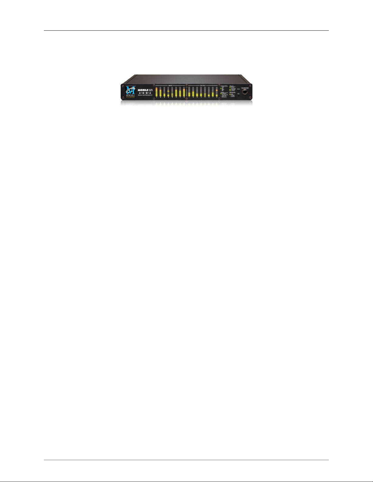
1. 2882 Quick Start Guide
Figure 1.1: Mobile I/O 2882
Prepare the unit for use
Unpack the 2882 and make sure all the parts are there:
• One Mobile I/O 2882 unit
• One IEC Power Cord appropriate for your area
• One 24-volt 48-watt world-ready external power supply
• One 30” IEEE 1394 9-pin to 6-pin FireWire Cable
• One 4.5 meter IEEE 1394 9-pin to 6-pin FireWire Cable
• Two Rack Ears w/ fasteners
• Rubber feet
• MIO Software CD-ROM
• Warranty/Registration Card
Bask in the look and feel of the 2882! Once you’re finished, connect the power supply, and connect your
monitors to Analog Out 1/2. Many people find it useful to put a pad between their amps or powered monitors
and the 2882’s outputs; this allows the 2882 to work at full digital resolution without overdriving the amplifiers.
23
Page 24
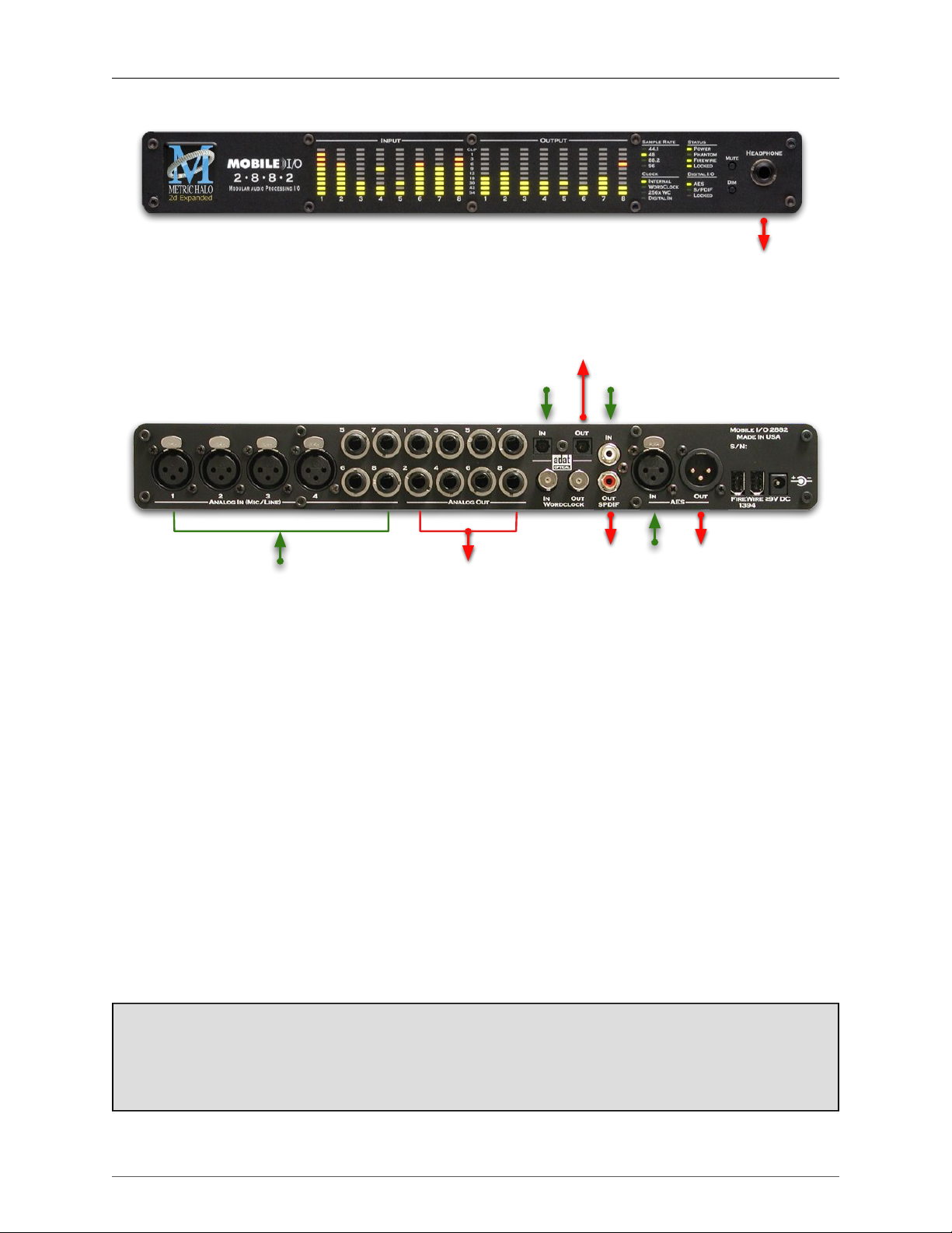
2882 Quick Start Guide
Analog
1-8
Cans
L/R
Digital
L/R
Digital
L/R
Digital
L/R
Digital
L/R
ADAT 1-8
Toslink 1-2
ADAT 1-8
Toslink 1-2
Green: Routable Inputs
Red: Routable Outputs
Analog
1-8
Figure 1.2: 2882 Routing
Connect the 2882
Go to your computer and install the driver and MIO Console application driver from the included disc (this
will require a restart). Please see the section on software installationif you need clarification. Connect the
FireWire cable between the 2882 and your computer, then go to the System Preferences and select it as the
system’s sound input and output.
Take a listen
Now we’re ready to listen. Don't launch MIO Console yet; open iTunes, turn its volume slider down and play
some music. Bring the volume up to a comfortable level, and try the Dim and Mute buttons. Enjoy simply
listening to music.
MIO Console
Once you’ve listened for a while, launch MIO Console. If you're launching MIO Console for the first time,
you'll see the factory default setup; more information on this is available in the Saving and Recalling Your
Setups section of this manual.
Using Legacy Interfaces
If you are also using an older Legacy interface without a 2d card, open the application’s preferences and
turn on “Legacy Support”. You will need to quit and relaunch MIO Console. All Metric Halo interfaces
manufactured since 2007 contain a 2d card.
24
Page 25
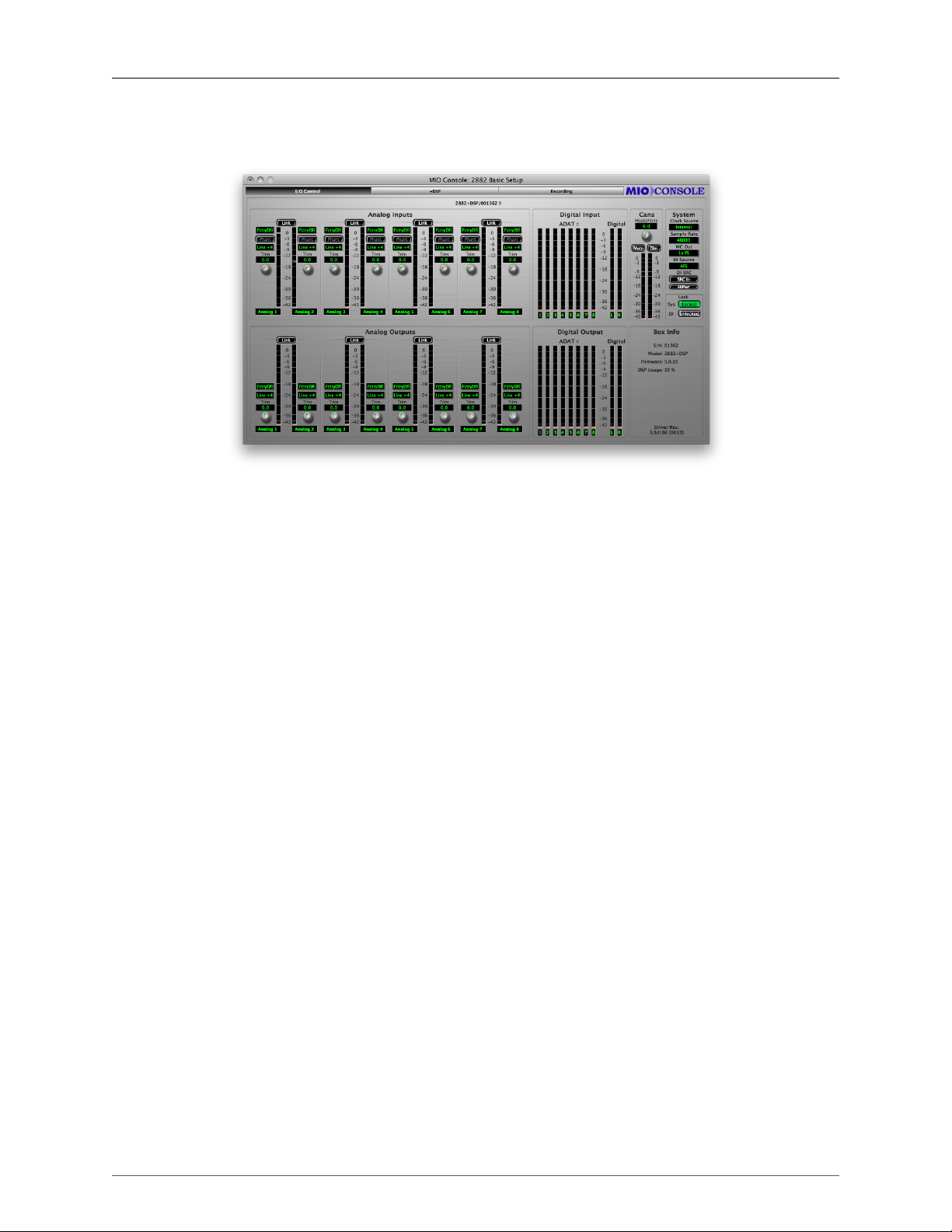
The Console window
2882 Quick Start Guide
Figure 1.3: Console Window
There are a few important things to look at here. To the right, the “System” column lets you set the clock
source, sample rate and whether the wordclock output is 1x or 256x rate. In the “Lock” column you can see
if the 2882 is receiving a valid clock on the selected source.
Toward the top of the window you will see the text “2882/xxx” where “xxx” is the serial number of the box.
By clicking on this you will get a menu of options for removal of offline boxes (you shouldn’t have any at
this point).
The I/O Control tab has metering and control for the analog I/O. You can link stereo pairs, set operating levels
and gain. The I/O Control tab is synchronized with the Front Panel; changes in one place are reflected in the
other. There is also metering for digital I/O. If you click on the +DSP tab, you have access to a “Virtual” DSP
area. Next is the “Recording” tab. Any channel that is assigned to a “FW” channel via a direct out or bus output
is available for recording via MIO Console’s Record Panel.
25
Page 26
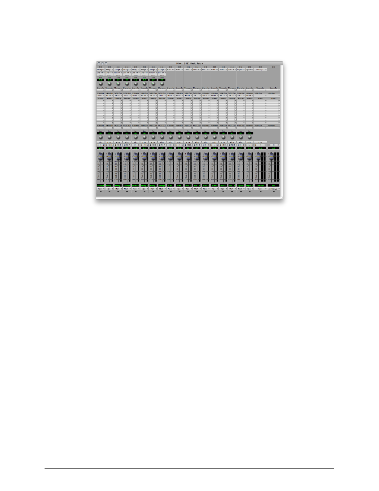
The Mixer window
2882 Quick Start Guide
Figure 1.4: Mixer Window
The Mixer window presents you with a familiar interface to the 2882. At the top of every channelstrip is a
pulldown list of available sources. For analog inputs you can select the input type, enable phantom power
and set gain. Below the head-amp area is the Character menu. This lets you select any of our DSP based
circuit emulations for your inputs, busses and outputs. Some are very subtle, so you may want to try different
Characters on different signals. Next is a pre-insert direct out. This lets you route the channelstrip to any unused
analog or digital output, as well as to “FW” channels. The FireWire channels allow you to return audio from
the 2882 to your computer.
Below Character are the insert slots. Here you can insert plugins, route to sends (additional busses), call up
macros (pre-made DSP processors) and instantiate graphs. A graph is a “DSP playground” where you can build
your own signal processing chains and save them for later recall. You’ll notice that there is another direct
out under the inserts- this one is post-insert. Any signal routed from this direct out has all of your inserted
processing applied, whereas the pre-insert direct out doesn’t.
The pan control reconfigures depending on the type of channel and the bus that it is assigned to:
• There are no pan controls on a channel assigned to a mono bus.
• Mono input channels will have a pan knob when assigned to stereo or LCR busses.
• Mono input channels assigned to LCRS through 7.1 busses will have joysticks. Right clicking on the
joystick will allow you to hard assign the input channel to a specific output channel, i.e. Center.
• Multichannel inputs (stereo and above) have no pan control.
Every input channel has a phase reverse button, as well as solo, mute and record enable (active if assigned
to FW). The names of the faders can be changed in the “Configure Mixer” pane available from the Mixer
menu. Finally, the pulldown menu at the bottom of the strip lets you assign the input to any available bus.
You can find more detail about the controls in the channelstrips in the Input Strip Details section of the MIO
Console overview.
If you go to the Window menu and select “Show Monitor Control Window” the software Monitor Controller will
appear. It is highly flexible, and controls the analog level control in the 2882. There is a wealth of knowledge
in the Monitor Controller section on how to set up and use the Monitor Controller.
26
Page 27
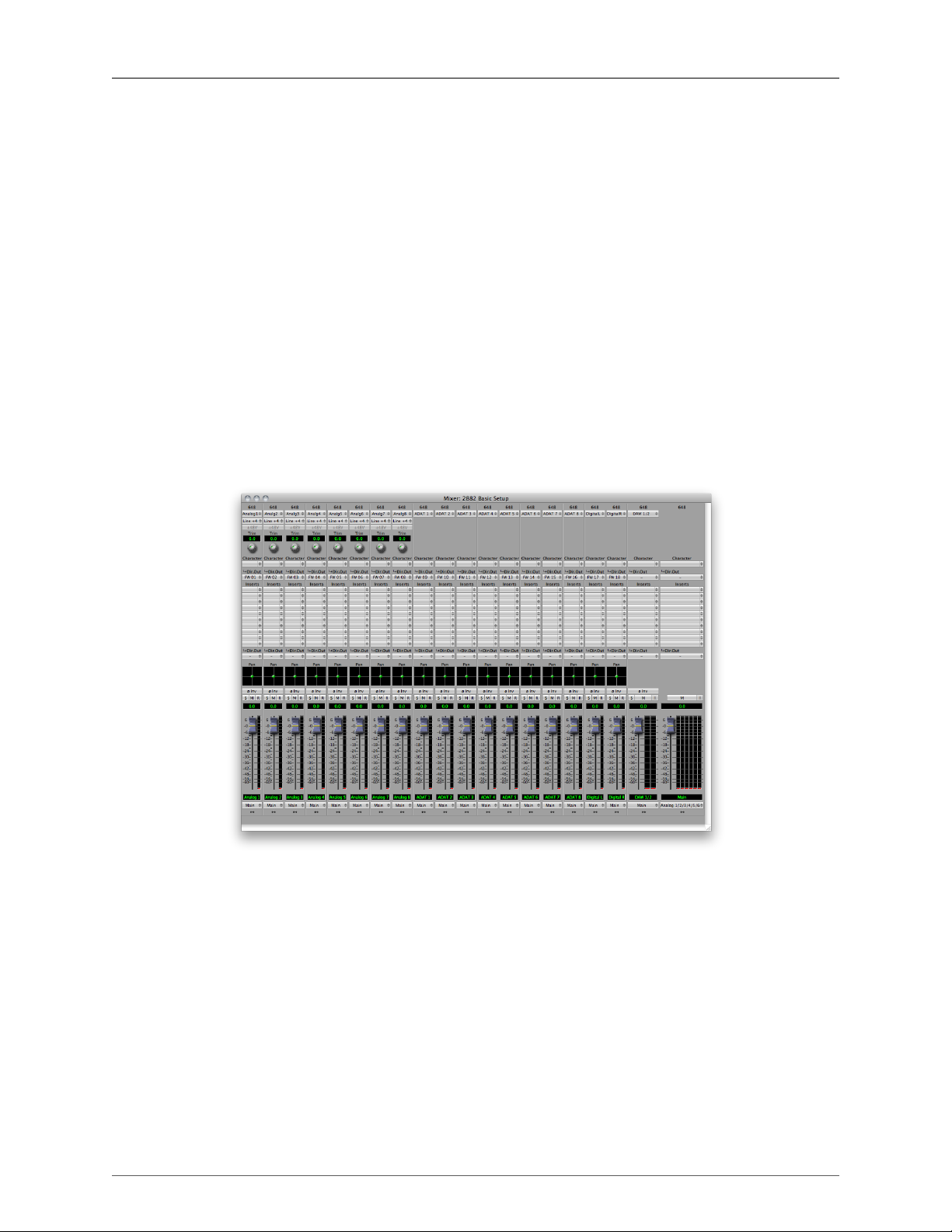
2882 Quick Start Guide
You should now be in a good position to fire up a native DAW and put the 2882 through its paces. Select
the 2882 as your audio interface in your DAW's hardware configuration; the analog inputs will be available
on inputs 1-8, ADAT will be available on 9-16 and AES/Spdif digital inputs will be available on 17-18 (as
determined by the FW channel assignments). Send your DAW’s signal to outputs 1/2 and it will come into the
2882 on DAW 1/2. By using the FW channels to send audio to your DAW and the DAW input returns from
your computer you have a virtual patchbay to route audio between your DAW and the 2882.
The 2882 and surround
If you’re working in surround, it’s easy to configure the 2882 for monitoring and processing. Go to the Mixer
menu and select “Configure Mixer”. At the top of the pane you’ll see the “Main” bus, which is stereo and a
Master. Master busses are routed to outputs, while Aux busses are routed back into Master busses (for returns,
subgroups, etc. ). If you click on the bus type you can change it from “Stereo” to whatever width you need ;
let’s say you’re working in 5.1. Select “5.1” and hit configure. Voila! All the mono channels now have joysticks
instead of pan knobs, and the Main bus is automatically routed to Analog 1-6. Your DAW is still coming in on
two channels, but that’s easy to change. Go to the top of the DAW 1/2 channelstrip and click on the assignment
pulldown. You have the choice of a mono channel, or a 6 channel strip. By selecting DAW 1-6, your audio will
come into the 2882 as positioned by your host. Your other choice would be to make this channel mono, and
add five more channelstrips via the Mixer menu. This way you can position your audio with the MIO Mixer.
Figure 1.5: Surround Mixer
To make it easier to monitor in surround, let’s use the Monitor Controller. Click on the assignment pulldown at
the bottom of the Main bus and select “N/C” to remove the assignment to the analog outs. Now hold down the
shift key and click the pulldown again; the Main bus was “multed” to the headphones in the template which
means it was routed to Analog 1/2 and the Cans at the same time. Now that we’re working in surround, the
Cans aren’t as useful. By holding down Shift and clicking on the Cans-Digital 4 line, we clear the mult. Now
click on the pulldown one more time and select “Add to Monitor Controller”. Go to the Window menu and
select “Show Monitor Control Window”.
The Monitor Controller shows the Main bus is the Monitor Source, but we need to define an output. Click the
“Configure” button to open the MC pane. Click “+” under Monitor Paths and you’ll have the option to add a
Monitor Output. Give the path a name (like “Surround”) and select 5.1 as the bus type. Now you can assign
your output channels. If you want to select your outputs sequentially, a shortcut is to hold down the Option
27
Page 28
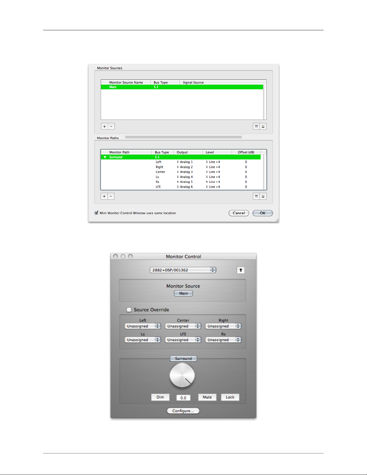
2882 Quick Start Guide
key when selecting the first channel. For example, hold down Option and click the assignment for the Left
channel and select Analog 1. The rest of the channels will fill in automatically.
Figure 1.6: Configuring the Monitor Controller
Choose "OK" and you now have a surround monitor controller!
Figure 1.7: The Configured Monitor Controller
28
Page 29

2882 Quick Start Guide
Unleash the DSP
Every 2882 is based on the 2d processing card and may be purchased with an optional +DSP license. The
+DSP can be added by the user at any time (except on Legacy interfaces); if you purchased a unit with the
+DSP license, it is preinstalled in the hardware and ready to go. This gives you powerful processing in the box,
and the ability to work with processing and monitoring whose latency is equivalent to the converter overhead.
There are two ways to access the DSP:
• You can insert processes directly in the mixer strip inserts; this works well for standalone processes like
eq, compressors, etc.
• Insert a graph +DSP ONLY. This lets you chain plugins together, use them in parallel, and create configurations that would be difficult (or impossible) with other platforms.
You should definitely check out the following processes:
• MIOStrip: Gating, EQ and compression powerhouse.
• Character: The sound of different analog circuits and devices available on any input, output or bus.
Some can be subtle, so stack them across an entire mix. Try SoftSat on your main bus; you'll like it.
• Haloverb: Great sounding reverb, doesn't use any CPU from your host. What's not to love?
You should read the DSP Implementation section to learn more about how to work with DSP, and the +DSP
documentation details the over 100 plug-ins available with the +DSP license.
This should get you started with the 2882!
Additional Resources
The 2882 is an exceptionally deep product, and there are many features, applications and workflows to discover. We have published a series of technical notes and tutorial movies that go in depth about the Mobile
I/Oplatform. Please take a look at them to learn more about the 2882: http://mhsecure.com/metric_halo/sup-
port/tutorials.html
29
Page 30
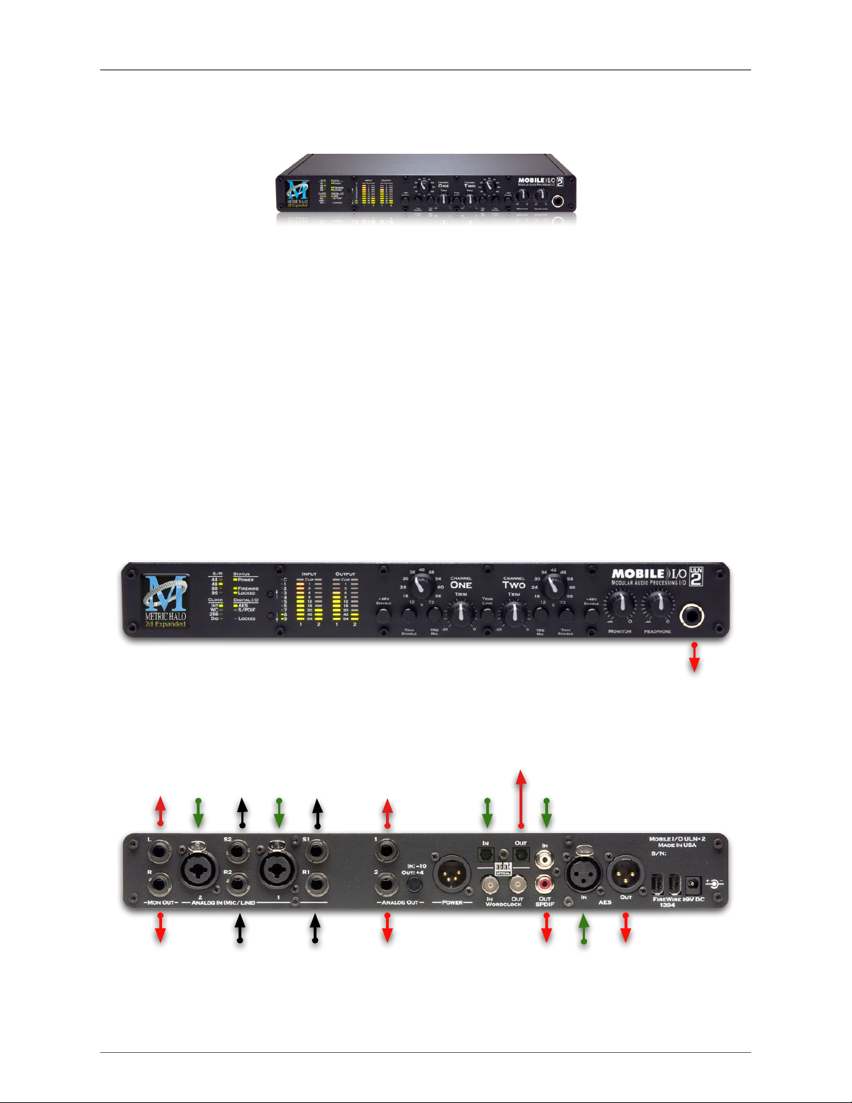
2. ULN-2 Quick Start Guide
Monitor
R
Analog
2
Monitor
L/R
Digital
L/R
Digital
L/R
Digital
L/R
Digital
L/R
ADAT 1-8
Toslink 1-2
ADAT 1-8
Toslink 1-2
Analog
1
Analog
1
Analog2Analog 2
Insert Send
Analog 1
Insert Send
Analog 2
Insert Return
Analog 1
Insert Return
Monitor
L
Green: Routable Inputs
Red: Routable Outputs
Black: Non-routable connections
Figure 2.1: Mobile I/O ULN-2
Prepare the unit for use
Unpack the ULN-2 and make sure all the parts are there:
• One Mobile I/O 2882 unit
• One IEC Power Cord appropriate for your area
• One 24-volt 48-watt world-ready external power supply
• One 30” IEEE 1394 9-pin to 6-pin FireWire Cable
• One 4.5 meter IEEE 1394 9-pin to 6-pin FireWire Cable
• Two Rack Ears w/ fasteners
• Rubber feet
• MIO Software CD-ROM
• Warranty/Registration Card
Bask in the look and feel of the ULN-2! Once you’re finished, connect the power supply, and connect your
monitors to Monitor Out L/R.
Figure 2.2: ULN-2 Routing
30
Page 31

ULN-2 Quick Start Guide
Connect the ULN-2
Go to your computer and install the driver and MIO Console application driver from the included disc (this
will require a restart). Please see the section on software installation if you need clarification. Connect the
FireWire cable between the ULN-2 and your computer, then go to the System Preferences and select it as the
system’s sound input and output.
Take a listen
Don't launch MIO Console yet; turn the Monitor level on the front panel down, open iTunes and play some
music. Bring the Monitor level up to a comfortable level and listen.
MIO Console
Once you’ve listened for a while, launch MIO Console. If you're launching MIO Console for the first time,
you'll see the factory default setup; more information on this is available in the Saving and Recalling Your
Setups section of this manual.
Using Legacy Interfaces
If you are also using an older Legacy interface without a 2d card, open the application’s preferences and
turn on “Legacy Support”. You will need to quit and relaunch MIO Console. All Metric Halo interfaces
manufactured since 2007 contain a 2d card.
The Console window
Figure 2.3: Console Window
There are a few important things to look at here. To the right, the “System” column lets you set the clock
source, sample rate and whether the wordclock output is 1x or 256x rate. In the “Lock” column you can see
if the ULN-2 is receiving a valid clock on the selected source.
Toward the top of the window you will see the text “ULN-2/xxx” where “xxx” is the serial number of the box.
By clicking on this you will get a menu of options for removal of offline boxes (you shouldn’t have any at
this point).
31
Page 32

ULN-2 Quick Start Guide
The I/O Control tab has metering for the analog and digital I/O. If you click on the +DSP tab, you have access
to a “Virtual” DSP area. Next is the “Recording” tab. Any channel that is assigned to a “FW” channel via a
direct out or bus output is available for recording via MIO Console’s Record Panel.
The Mixer window
Figure 2.4: Mixer Window
The Mixer window presents you with a familiar interface to the ULN-2. At the top of every channelstrip is
a pulldown list of available sources. Below that is the Character menu. This lets you select any of our DSP
based circuit emulations for your inputs, busses and outputs. Some are very subtle, so you may want to try
different Characters on different signals. Next is a pre-insert direct out. This lets you route the channelstrip to
any unused analog or digital output, as well as to “FW” channels. The FireWire channels allow you to return
audio from the ULN-2 to your computer.
Below Character are the insert slots. Here you can insert plugins, route to sends (additional busses), call up
macros (pre-made DSP processors) and instantiate graphs. A graph is a “DSP playground” where you can build
your own signal processing chains and save them for later recall. You’ll notice that there is another direct
out under the inserts- this one is post-insert. Any signal routed from this direct out has all of your inserted
processing applied, whereas the pre-insert direct out doesn’t.
The pan control reconfigures depending on the type of channel and the bus that it is assigned to:
• There are no pan controls on a channel assigned to a mono bus.
• Mono input channels will have a pan knob when assigned to stereo or LCR busses.
32
Page 33

ULN-2 Quick Start Guide
• Mono input channels assigned to LCRS through 7.1 busses will have joysticks. Right clicking on the
joystick will allow you to hard assign the input channel to a specific output channel, i.e. Center.
• Multichannel inputs (stereo and above) have no pan control.
Keep in mind that the while ULN-2 is primarily a stereo device in the analog domain, it is possible to work in
multichannel by using the optical I/O.
Every input channel has a phase reverse button, as well as solo, mute and record enable (active if assigned
to FW). The names of the faders can be changed in the “Configure Mixer” pane available from the Mixer
menu. Finally, the pulldown menu at the bottom of the strip lets you assign the input to any available bus.
You can find more detail about the controls in the channelstrips in the Input Strip Details section of the MIO
Console overview.
If you go to the Window menu and select “Show Monitor Control Window” you will be presented with our
software Monitor Controller. It is highly flexible, and controls the analog level control in the ULN-2. There is
a wealth of knowledge in the Monitor Controller section on how to set up and use the Monitor Controller.
You should now be in a good position to fire up a native DAW and put the ULN-2 through its paces. Select
the ULN-2 as your audio interface; the analog inputs will be inputs 1-2, AES/Spdif digital inputs will be 3-4
and ADAT will be 5-12 (as determined by the FW channel assignments). Send your DAW’s signal to outputs
1/2 and it will come into the ULN-2 on DAW 1/2. By using the FW channels to send audio to your DAW
and the DAW input returns from your computer you have a virtual patchbay to route audio between your
DAW and the ULN-2.
The ULN-2 and surround
If you’re working in surround it’s easy to configure the ULN-2 for processing and monitoring via an ADAT
based D/A . Go to the Mixer menu and select “Configure Mixer”. At the top of the pane you’ll see the “Main”
bus, which is stereo and a Master. Master busses are routed to outputs, while Aux busses are routed back
into Master busses (for returns, subgroups, etc. ). If you click on the bus type you can change it from “Stereo”
to whatever width you need; let’s say you’re working in 5.1. Select “5.1” and hit configure. Voila! All the
mono channels now have joysticks instead of pan knobs, and the Main bus is automatically routed to Analog
1-6. Your DAW is still coming in on two channels, but that’s easy to change. Go to the top of the DAW 1/2
channelstrip and click on the assignment pulldown. You have the choice of a mono channel, or a 6 channel
strip. By selecting DAW 1-6, your audio will come into the ULN-2 as positioned by your host. Your other
choice would be to make this channel mono, and add five more channelstrips via the Mixer menu. This way
you can position your audio with the MIO Mixer.
33
Page 34

ULN-2 Quick Start Guide
Figure 2.5: Surround Mixer
To make it easier to monitor in surround, let’s use the Monitor Controller. Click on the assignment pulldown at
the bottom of the Main bus and select “N/C” to remove the assignment to the analog outs. Now hold down the
shift key and click the pulldown again; the Main bus was “multed” to the Monitor bus in the template which
means it was routed to Analog 1/2 and the Monitor at the same time. Now that we’re working in surround,
we need to send to the ADAT outs. By holding down shift and clicking on the Monitor L-n/c line, we clear the
mult. Now click on the pulldown one more time and select “Add to Monitor Controller”. Go to the Window
menu and select “Show Monitor Control Window”.
The Monitor Controller shows the Main bus is the Monitor Source, but we need to define an output. Click the
“Configure” button to open the MC pane. Click the “+” under Monitor Paths and you’ll have the option to add
a Monitor Output. Give the path a name (like “Surround”) and select 5.1 as the bus type. Now you can assign
your output channels. If you want to select your outputs sequentially, a shortcut is to hold down the Option
key when selecting the first channel. For example, hold down Option and click the assignment for the Left
channel and select ADAT 1. The rest of the channels will fill in automatically.
34
Page 35

ULN-2 Quick Start Guide
Figure 2.6: Configuring the Monitor Controller
Choose "OK" and you now have a surround monitor controller!
Figure 2.7: The Configured Monitor Controller
35
Page 36

ULN-2 Quick Start Guide
Unleash the DSP
Every ULN-2 is based on the 2d processing card and may be purchased with an optional +DSP license. The
+DSP can be added by the user at any time (except on Legacy interfaces); if you purchased a unit with the
+DSP license, it is preinstalled in the hardware and ready to go. This gives you powerful processing in the box,
and the ability to work with processing and monitoring whose latency is equivalent to the converter overhead.
There are two ways to access the DSP:
• You can insert processes directly in the mixer strip inserts; this works well for standalone processes like
eq, compressors, etc.
• Insert a graph +DSP ONLY. This lets you chain plugins together, use them in parallel, and create configurations that would be difficult (or impossible) with other platforms.
You should definitely check out the following processes:
• MIOStrip: Gating, EQ and compression powerhouse.
• Character: The sound of different analog circuits and devices available on any input, output or bus.
Some can be subtle, so stack them across an entire mix. Try SoftSat on your main bus; you'll like it.
• Haloverb: Great sounding reverb, doesn't use any CPU from your host. What's not to love?
You should read the DSP Implementation section to learn more about how to work with DSP, and the +DSP
documentation details the over 100 plug-ins available with the +DSP license.
This should get you started with the ULN-2!
Additional Resources
The ULN-2 is an exceptionally deep product, and there are many features, applications and workflows to
discover. We have published a series of technical notes and tutorial movies that go in depth about the Mobile
I/O platform. Please take a look at them to learn more about the ULN-2: http://mhsecure.com/metric_halo/
support/tutorials.html
36
Page 37

3. LIO-8 Quick Start Guide
Figure 3.1: LIO-8
Prepare the unit for use
Unpack the LIO-8 and make sure all the parts are there:
• One LIO-8 unit
• One IEC Power Cord appropriate for your area
• One 24-volt 48-watt world-ready external power supply
• One 30” IEEE 1394 9-pin to 6-pin FireWire Cable
• One 4.5 meter IEEE 1394 9-pin to 6-pin FireWire Cable
• Two Rack Ears w/ fasteners
• Rubber feet
• Configuration jumpers
• MIO Software CD-ROM
• Warranty/Registration Card
Bask in the look and feel of the LIO-8! Once you’re finished, connect the power supply. Now connect your
input and output cables along with your monitors and signal sources. Your monitors should be connected to
Analog Out 1/2, either via a DB25 cable or the 1/4" TRS jacks. Turn the unit on using the front panel switch.
Cool, isn’t it?
37
Page 38

LIO-8 Quick Start Guide
Analog
2
Cans
L/R
Digital 1-8
Analog
1
Send 1-8
(Mult of Line 1-8)
Green: Routable Inputs
Red: Routable Outputs
Black: Non-routable connections
Line
1
Line
2
FW
20
DAW
19
Analog
(Line)
1-8
Analog
1-8
Figure 3.2: LIO-8 Routing
Connect the LIO-8
Go to your computer and install the driver and MIO Console application driver from the included disc (this
will require a restart). Please see the section on software installation if you need clarification. Connect the
FireWire cable between the LIO-8 and your computer, then go to the System Preferences and select it as the
system’s sound input and output.
Get familiar with the front panel
Look at the LED under the Monitor Control encoder; the “Monitor Control” LED should be illuminated. If
“Cans” is lit, push the encoder to switch it (all encoders have shaft buttons). The LED should be green; if it is
yellow, push the “Dim” button. If it is red push the “Mute” button. Now that you’re sure that you’re looking at
the Monitor Controller and that is not dimmed and unmuted, turn it down. The meters are now showing the
gain value of the Monitor Controller. This will happen any time you adjust an encoder.
Take a listen
Now we’re ready to listen. Don't launch MIO Console yet; open iTunes and play some music. Turn up the
Monitor Controller to a comfortable level, then try the Dim and Mute buttons again. Next, connect a pair of
headphones to the front panel. Push the Mute button to turn off your monitors, then press the Monitor encoder.
Turn the level down (you’re now controlling the headphone amplifier), then put on your cans and turn up
the encoder.
MIO Console
Once you’re comfortable with the Monitor Controller and how it works, launch MIO Console. If you're launching MIO Console for the first time, you'll see the factory default setup; more information on this is available
in the Saving and Recalling Your Setups section of this manual.
38
Page 39

LIO-8 Quick Start Guide
Using Legacy Interfaces
If you are also using an older Legacy interface without a 2d card, open the application’s preferences and
turn on “Legacy Support”. You will need to quit and relaunch MIO Console. All Metric Halo interfaces
manufactured since 2007 contain a 2d card.
The Console window
Figure 3.3: Console Window
There are a few important things to look at here. To the right, the “System” column lets you set the clock
source, sample rate and whether the wordclock output is 1x or 256x rate. In the “Lock” column you can see
if the LIO-8 is receiving a valid clock on the selected source.
Toward the top of the window you will see the text “LIO-8/xxx” where “xxx” is the serial number of the box.
By clicking on this you will get a menu of options for removal of offline boxes (you shouldn’t have any at
this point).
The I/O Control tab has metering and control for the analog I/O. You can link stereo pairs, set operating levels
and gain. The I/O Control tab is synchronized with the Front Panel; changes in one place are reflected in the
other. There is also metering for digital I/O. If you click on the +DSP tab, you have access to a “Virtual” DSP
area. Next is the “Recording” tab. Any channel that is assigned to a “FW” channel via a direct out or bus output
is available for recording via MIO Console’s Record Panel.
39
Page 40

The Mixer window
LIO-8 Quick Start Guide
Figure 3.4: Mixer Window
The Mixer window presents you with a familiar interface to the LIO-8. At the top of every channelstrip is a
pulldown list of available sources. For analog inputs you can select the input type, enable phantom power
and set gain. Below the head-amp area is the Character menu. This lets you select any of our DSP based
circuit emulations for your inputs, busses and outputs. Some are very subtle, so you may want to try different
Characters on different signals. Next is a pre-insert direct out. This lets you route the channelstrip to any unused
analog or digital output, as well as to “FW” channels. The FireWire channels allow you to return audio from
the LIO-8 to your computer.
Below Character are the insert slots. Here you can insert plugins, route to sends (additional busses), call up
macros (pre-made DSP processors) and instantiate graphs. A graph is a “DSP playground” where you can build
your own signal processing chains and save them for later recall. You’ll notice that there is another direct
out under the inserts- this one is post-insert. Any signal routed from this direct out has all of your inserted
processing applied, whereas the pre-insert direct out doesn’t.
The pan control reconfigures depending on the type of channel and the bus that it is assigned to:
• There are no pan controls on a channel assigned to a mono bus.
• Mono input channels will have a pan knob when assigned to stereo or LCR busses.
• Mono input channels assigned to LCRS through 7.1 busses will have joysticks. Right clicking on the
joystick will allow you to hard assign the input channel to a specific output channel, i.e. Center.
• Multichannel inputs (stereo and above) have no pan control.
Every input channel has a phase reverse button, as well as solo, mute and record enable (active if assigned
to FW). The names of the faders can be changed in the “Configure Mixer” pane available from the Mixer
menu. Finally, the pulldown menu at the bottom of the strip lets you assign the input to any available bus.
You can find more detail about the controls in the channelstrips in the Input Strip Details section of the MIO
Console overview.
If you go to the Window menu and select “Show Monitor Control Window” the software Monitor Controller will
appear. It is highly flexible, and controls the analog level control in the LIO-8. There is a wealth of knowledge
in the Monitor Controller section on how to set up and use the Monitor Controller.
40
Page 41

LIO-8 Quick Start Guide
You should now be in a good position to fire up a native DAW and put the LIO-8 through its paces. Select the
LIO-8 as your audio interface; the analog inputs will be inputs 1-8, digital inputs will be 9-16 (as determined by
the FW channel assignments). Send your DAW’s signal to outputs 1/2 and it will come into the LIO-8 on DAW
1/2. By using the FW channels to send audio to your DAW and the DAW input returns from your computer
you have a virtual patchbay to route audio between your DAW and the LIO-8.
The LIO-8 and surround
If you’re working in surround, it’s easy to configure the LIO-8 for monitoring and processing. Go to the Mixer
menu and select “Configure Mixer”. At the top of the pane you’ll see the “Main” bus, which is stereo and a
Master. Master busses are routed to outputs, while Aux busses are routed back into Master busses (for returns,
subgroups, etc. ). If you click on the bus type you can change it from “Stereo” to whatever width you need ;
let’s say you’re working in 5.1. Select “5.1” and hit configure. Voila! All the mono channels now have joysticks
instead of pan knobs, and the Main bus is automatically routed to Analog 1-6. Your DAW is still coming in on
two channels, but that’s easy to change. Go to the top of the DAW 1/2 channelstrip and click on the assignment
pulldown. You have the choice of a mono channel, or a 6 channel strip. By selecting DAW 1-6, your audio will
come into the LIO-8 as positioned by your host. Your other choice would be to make this channel mono, and
add five more channelstrips via the Mixer menu. This way you can position your audio with the MIO Mixer.
Figure 3.5: Surround Mixer
To make it easier to monitor in surround, let’s use the Monitor Controller. Click on the assignment pulldown at
the bottom of the Main bus and select “N/C” to remove the assignment to the analog outs. Now hold down the
shift key and click the pulldown again; the Main bus was “multed” to the headphones in the template which
means it was routed to Analog 1/2 and the Cans at the same time. Now that we’re working in surround, the
Cans aren’t as useful. By holding down Shift and clicking on the Cans-Digital 4 line, we clear the mult. Now
click on the pulldown one more time and select “Add to Monitor Controller”. Go to the Window menu and
select “Show Monitor Control Window”.
The Monitor Controller shows the Main bus is the Monitor Source, but we need to define an output. Click the
“Configure” button to open the MC pane. Click “+” under Monitor Paths and you’ll have the option to add a
Monitor Output. Give the path a name (like “Surround”) and select 5.1 as the bus type. Now you can assign
41
Page 42

LIO-8 Quick Start Guide
your output channels. If you want to select your outputs sequentially, a shortcut is to hold down the Option
key when selecting the first channel. For example, hold down Option and click the assignment for the Left
channel and select Analog 1. The rest of the channels will fill in automatically. They default to Monitor level,
which is optimized for connecting to self powered monitors or amplifiers. If you are connecting to another
device like a mixing console you can change this to Line.
Figure 3.6: Configuring the Monitor Controller
Choose "OK" and you now have a surround monitor controller!
42
Page 43

LIO-8 Quick Start Guide
Figure 3.7: The Configured Monitor Controller
Unleash the DSP
Every LIO-8 is based on the 2d processing card and may be purchased with an optional +DSP license. The
+DSP can be added by the user at any time (except on Legacy interfaces); if you purchased a unit with the
+DSP license, it is preinstalled in the hardware and ready to go. This gives you powerful processing in the box,
and the ability to work with processing and monitoring whose latency is equivalent to the converter overhead.
There are two ways to access the DSP:
• You can insert processes directly in the mixer strip inserts; this works well for standalone processes like
eq, compressors, etc.
• Insert a graph +DSP ONLY. This lets you chain plugins together, use them in parallel, and create configurations that would be difficult (or impossible) with other platforms.
You should definitely check out the following processes:
• MIOStrip: Gating, EQ and compression powerhouse.
• Character: The sound of different analog circuits and devices available on any input, output or bus.
Some can be subtle, so stack them across an entire mix. Try SoftSat on your main bus; you'll like it.
• Haloverb: Great sounding reverb, doesn't use any CPU from your host. What's not to love?
You should read the DSP Implementation section to learn more about how to work with DSP, and the +DSP
documentation details the over 100 plug-ins available with the +DSP license.
This should get you started with the LIO-8!
Additional Resources
The LIO-8 is an exceptionally deep product, and there are many features, applications and workflows to
discover. We have published a series of technical notes and tutorial movies that go in depth about the Mobile
43
Page 44

LIO-8 Quick Start Guide
I/O platform. Please take a look at them to learn more about the LIO-8: http://mhsecure.com/metric_halo/
support/tutorials.html
44
Page 45

4. ULN-8 Quick Start Guide
Figure 4.1: ULN-8
Prepare the unit for use
Unpack the ULN-8 and make sure all the parts are there:
• One ULN-8 unit
• One IEC Power Cord appropriate for your area
• One 24-volt 48-watt world-ready external power supply
• One 30” IEEE 1394 9-pin to 6-pin FireWire Cable
• One 4.5 meter IEEE 1394 9-pin to 6-pin FireWire Cable
• Two Rack Ears w/ fasteners
• Rubber feet
• Configuration jumpers
• MIO Software CD-ROM
• Warranty/Registration Card
Bask in the look and feel of the ULN-8! Once you’re finished, connect the power supply. Now connect your
input and output cables along with your monitors and signal sources. Your monitors should be connected to
Analog Out 1/2, either via a DB25 cable or the 1/4" TRS jacks. Turn the unit on using the front panel switch.
Cool, isn’t it?
45
Page 46

ULN-8 Quick Start Guide
Analog
2
Digital 1-8
Analog
1
Analog
(Mic)
1-8
Send 1-8
(Mirrors selected
Mic/Line input)
Green: Routable Inputs
Red: Routable Outputs
Black: Non-routable connections
Line
1
FW
20
DAW
19
Analog
(Line)
1-8
Analog
1-8
Cans
L/R
Line
2
Figure 4.2: ULN-8 Routing
Connect the ULN-8
Go to your computer and install the driver and MIO Console application driver from the included disc (this
will require a restart). Please see the section on software installation if you need clarification. Connect the
FireWire cable between the ULN-8 and your computer, then go to the System Preferences and select it as the
system’s sound input and output.
Get familiar with the front panel
Look at the LED under the Monitor Control encoder; the “Monitor Control” LED should be illuminated. If
“Cans” is lit, push the encoder to switch it (all encoders have shaft buttons). The LED should be green; if it is
yellow, push the “Dim” button. If it is red push the “Mute” button. Now that you’re sure that you’re looking at
the Monitor Controller and that is not dimmed and unmuted, turn it down. The meters are now showing the
gain value of the Monitor Controller. This will happen any time you adjust an encoder.
Take a listen
Now we’re ready to listen. Don't launch MIO Console yet; open iTunes and play some music. Turn up the
Monitor Controller to a comfortable level, then try the Dim and Mute buttons again. Next, connect a pair of
headphones to the front panel. Push the Mute button to turn off your monitors, then press the Monitor encoder.
Turn the level down (you’re now controlling the headphone amplifier), then put on your cans and turn up
the encoder.
MIO Console
Once you’re comfortable with the Monitor Controller and how it works, launch MIO Console. If you're launching MIO Console for the first time, you'll see the factory default setup; more information on this is available
in the Saving and Recalling Your Setups section of this manual.
46
Page 47

ULN-8 Quick Start Guide
Using Legacy Interfaces
If you are also using an older Legacy interface without a 2d card, open the application’s preferences and
turn on “Legacy Support”. You will need to quit and relaunch MIO Console. All Metric Halo interfaces
manufactured since 2007 contain a 2d card.
The Console window
Figure 4.3: Console Window
There are a few important things to look at here. To the right, the “System” column lets you set the clock
source, sample rate and whether the wordclock output is 1x or 256x rate. In the “Lock” column you can see
if the ULN-8 is receiving a valid clock on the selected source and use the “DI” buttons to select which AES
input pair should be used as a clock source if you are clocking via “Digital”.
Toward the top of the window you will see the text “ULN-8/xxx” where “xxx” is the serial number of the box.
By clicking on this you will get a menu of options, including “Front Panel Prefs”. If you select this you will
bring up a pane that will let you tailor the front panel to your liking. You can also remove offline boxes (you
shouldn’t have any at this point).
The I/O Control tab has metering and control for the analog I/O. You can link stereo pairs, set operating levels
and gain. The I/O Control tab is synchronized with the Front Panel; changes in one place are reflected in the
other. There is also metering for digital I/O. If you click on the +DSP tab, you have access to a “Virtual” DSP
area. Next is the “Recording” tab. Any channel that is assigned to a “FW” channel via a direct out or bus output
is available for recording via MIO Console’s Record Panel.
47
Page 48

The Mixer window
ULN-8 Quick Start Guide
Figure 4.4: Mixer Window
The Mixer window presents you with a familiar interface to the ULN-8. At the top of every channelstrip is a
pulldown list of available sources. For analog inputs you can select the input type, enable phantom power
and set gain. Below the head-amp area is the Character menu. This lets you select any of our DSP based
circuit emulations for your inputs, busses and outputs. Some are very subtle, so you may want to try different
Characters on different signals. Next is a pre-insert direct out. This lets you route the channelstrip to any unused
analog or digital output, as well as to “FW” channels. The FireWire channels allow you to return audio from
the ULN-8 to your computer.
Below Character are the insert slots. Here you can insert plugins, route to sends (additional busses), call up
macros (pre-made DSP processors) and instantiate graphs. A graph is a “DSP playground” where you can build
your own signal processing chains and save them for later recall. You’ll notice that there is another direct
out under the inserts- this one is post-insert. Any signal routed from this direct out has all of your inserted
processing applied, whereas the pre-insert direct out doesn’t.
The pan control reconfigures depending on the type of channel and the bus that it is assigned to:
• There are no pan controls on a channel assigned to a mono bus.
• Mono input channels will have a pan knob when assigned to stereo or LCR busses.
• Mono input channels assigned to LCRS through 7.1 busses will have joysticks. Right clicking on the
joystick will allow you to hard assign the input channel to a specific output channel, i.e. Center.
• Multichannel inputs (stereo and above) have no pan control.
Every input channel has a phase reverse button, as well as solo, mute and record enable (active if assigned
to FW). The names of the faders can be changed in the “Configure Mixer” pane available from the Mixer
menu. Finally, the pulldown menu at the bottom of the strip lets you assign the input to any available bus.
You can find more detail about the controls in the channelstrips in the Input Strip Details section of the MIO
Console overview.
If you go to the Window menu and select “Show Monitor Control Window” you will be presented with our
software Monitor Controller. It is highly flexible, and controls the analog level control in the ULN-8. There is
a wealth of knowledge in the Monitor Controller section on how to set up and use the Monitor Controller.
48
Page 49

ULN-8 Quick Start Guide
You should now be in a good position to fire up a native DAW and put the ULN-8 through its paces. Select the
ULN-8 as your audio interface; the analog inputs will be inputs 1-8, digital inputs will be 9-16 (as determined
by the FW channel assignments). Send your DAW’s signal to outputs 1/2 and it will come into the ULN-8
on DAW 1/2. By using the FW channels to send audio to your DAW and the DAW input returns from your
computer you have a virtual patchbay to route audio between your DAW and the ULN-8.
The ULN-8 and surround
If you’re working in surround, it’s easy to configure the ULN-8 for monitoring and processing. Go to the Mixer
menu and select “Configure Mixer”. At the top of the pane you’ll see the “Main” bus, which is stereo and a
Master. Master busses are routed to outputs, while Aux busses are routed back into Master busses (for returns,
subgroups, etc. ). If you click on the bus type you can change it from “Stereo” to whatever width you need ;
let’s say you’re working in 5.1. Select “5.1” and hit configure. Voila! All the mono channels now have joysticks
instead of pan knobs, and the Main bus is automatically routed to Analog 1-6. Your DAW is still coming in on
two channels, but that’s easy to change. Go to the top of the DAW 1/2 channelstrip and click on the assignment
pulldown. You have the choice of a mono channel, or a 6 channel strip. By selecting DAW 1-6, your audio will
come into the ULN-8 as positioned by your host. Your other choice would be to make this channel mono, and
add five more channelstrips via the Mixer menu. This way you can position your audio with the MIO Mixer.
Figure 4.5: Surround Mixer
To make it easier to monitor in surround, let’s use the Monitor Controller. Click on the assignment pulldown at
the bottom of the Main bus and select “N/C” to remove the assignment to the analog outs. Now hold down the
shift key and click the pulldown again; the Main bus was “multed” to the headphones in the template which
means it was routed to Analog 1/2 and the Cans at the same time. Now that we’re working in surround, the
Cans aren’t as useful. By holding down Shift and clicking on the Cans-Digital 4 line, we clear the mult. Now
click on the pulldown one more time and select “Add to Monitor Controller”. Go to the Window menu and
select “Show Monitor Control Window”.
The Monitor Controller shows the Main bus is the Monitor Source, but we need to define an output. Click the
“Configure” button to open the MC pane. Click “+” under Monitor Paths and you’ll have the option to add a
Monitor Output. Give the path a name (like “Surround”) and select 5.1 as the bus type. Now you can assign
49
Page 50

ULN-8 Quick Start Guide
your output channels. If you want to select your outputs sequentially, a shortcut is to hold down the Option
key when selecting the first channel. For example, hold down Option and click the assignment for the Left
channel and select Analog 1. The rest of the channels will fill in automatically. They default to Monitor level,
which is optimized for connecting to self powered monitors or amplifiers. If you are connecting to another
device like a mixing console you can change this to Line.
Figure 4.6: Configuring the Monitor Controller
Choose "OK" and you now have a surround monitor controller!
50
Page 51

ULN-8 Quick Start Guide
Figure 4.7: The Configured Monitor Controller
Unleash the DSP
Every ULN-8 is based on the 2d processing card and includes a +DSP license. This gives you powerful processing in the box, and the ability to work with processing and monitoring whose latency is equivalent to the
converter overhead.
There are two ways to access the DSP:
• You can insert processes directly in the mixer strip inserts; this works well for standalone processes like
eq, compressors, etc.
• Insert a graph +DSP ONLY. This lets you chain plugins together, use them in parallel, and create configurations that would be difficult (or impossible) with other platforms.
You should definitely check out the following processes:
• MIOStrip: Gating, EQ and compression powerhouse.
• Character: The sound of different analog circuits and devices available on any input, output or bus.
Some can be subtle, so stack them across an entire mix. Try SoftSat on your main bus; you'll like it.
• Haloverb: Great sounding reverb, doesn't use any CPU from your host. What's not to love?
You should read the DSP Implementation section to learn more about how to work with DSP, and the +DSP
documentation details the over 100 plug-ins available with the +DSP license.
This should get you started with the ULN-8!
Additional Resources
The ULN-8 is an exceptionally deep product, and there are many features, applications and workflows to
discover. We have published a series of technical notes and tutorial movies that go in depth about the Mobile
51
Page 52

ULN-8 Quick Start Guide
I/O platform. Please take a look at them to learn more about the ULN-8: http://mhsecure.com/metric_halo/
support/tutorials.html
52
Page 53

Part II. Interfaces
Page 54

Table of Contents
5. 2882 Users Guide ...................................................................................................................... 56
2882 Overview ...................................................................................................................... 56
What it is ....................................................................................................................... 56
What it has .................................................................................................................... 56
What you need to use it ................................................................................................. 57
What comes with it ........................................................................................................ 57
Using the 2882 Hardware ....................................................................................................... 58
2882 Front Panel ............................................................................................................ 58
2882 Rear Panel ............................................................................................................. 59
2882 Signal Flow ........................................................................................................... 60
Making connections to the 2882 ...................................................................................... 60
2882 Specifications ................................................................................................................. 65
6. ULN-2 Users Guide .................................................................................................................... 69
ULN-2 Overview .................................................................................................................... 69
What it is ....................................................................................................................... 69
What it has .................................................................................................................... 69
What you need to use it ................................................................................................. 70
What comes with it ........................................................................................................ 70
Using the ULN-2 Hardware ..................................................................................................... 71
ULN-2 Front Panel ......................................................................................................... 71
ULN-2 Rear Panel .......................................................................................................... 73
Signal Flow .................................................................................................................... 74
Making connections to the ULN-2 ................................................................................... 74
ULN-2 Specifications .............................................................................................................. 79
7. LIO-8 Users Guide ..................................................................................................................... 84
LIO-8 Overview ..................................................................................................................... 84
What it is ....................................................................................................................... 84
What it has .................................................................................................................... 84
What you need to use it ................................................................................................. 85
What comes with it ........................................................................................................ 85
Using the LIO-8 Hardware ...................................................................................................... 87
LIO-8 Front Panel ........................................................................................................... 87
LIO-8 Rear Panel ............................................................................................................ 88
Signal Flow .................................................................................................................... 89
Making connections to the LIO-8 ..................................................................................... 89
LIO-8 Specifications ................................................................................................................ 92
8. ULN-8 Users Guide .................................................................................................................... 97
ULN-8 Overview .................................................................................................................... 97
What it is ....................................................................................................................... 97
What it has .................................................................................................................... 97
What you need to use it ................................................................................................. 98
What comes with it ........................................................................................................ 98
Using the ULN-8 Hardware ................................................................................................... 100
ULN-8 Front Panel ........................................................................................................ 100
ULN-8 Rear Panel ......................................................................................................... 101
Signal Flow .................................................................................................................. 102
Making connections to the ULN-8 ................................................................................. 102
ULN-8 Specifications ............................................................................................................ 105
9. ULN/LIO-8 Front Panel Guide ................................................................................................... 111
Front Panel Overview .......................................................................................................... 111
Sample Rate Indicators and Control ................................................................................ 111
54
Page 55

Interfaces
Clock Source Indicators and Control .............................................................................. 112
Control Mode Indicators and Selector ............................................................................. 112
I/O Trim Mode Indicators and Selector ........................................................................... 113
Channel Mode Indicators .............................................................................................. 113
Per Channel Control Knobs ........................................................................................... 114
High Resolution Meters ................................................................................................. 114
System Status Indicators ................................................................................................ 116
AES Status Indicators ..................................................................................................... 116
Monitor Control Section ................................................................................................ 117
Front Panel DI Inputs .................................................................................................... 117
Control Mode Details ............................................................................................................ 118
Monitor ........................................................................................................................ 118
Preset ........................................................................................................................... 119
Input ............................................................................................................................ 119
Link ............................................................................................................................. 119
+48 ............................................................................................................................. 120
U/M — User Mode ....................................................................................................... 120
Input Trim .................................................................................................................... 120
Meters on the Knobs ..................................................................................................... 121
Output Trim ................................................................................................................. 121
Illumination (Brightness) Adjustment ....................................................................................... 121
Front Panel Preferences in MIO Console ................................................................................. 121
Infrared Remote operation ..................................................................................................... 123
55
Page 56

5. 2882 Users Guide
2882 Overview
Figure 5.1: Mobile I/O 2882
What it is
Mobile I/O is a portable, high–quality, modular FireWire–based multi-format audio converter, interface, and
processor for professional audio applications. The 2882 model line is equipped with eight balanced analog
inputs (4 on XLR and 4 on 1/4" TRS), two channels of Digital I/O (AES/EBU and S/PDIF), eight channels of
ADAT® optical I/O support (switchable to 2 channel TOSLINK), and eight balanced analog outputs (1/4" TRS),
as well as wordclock in/out and 2 IEEE 1394 FireWire connectors that support 400 Mbs operation. All inputs
and outputs are capable of 24-bit/ 96kHz operation.
What it has
• 18 simultaneous input channels and 20 simultaneous output channels
• full 24 bit/96kHz audio
• 8 independent channels of mic-pre with switchable phantom power
• Fully Portable Capabilities – Bus and Battery Powerable
• Rack Mount Kit
• 44.1, 48, 88.2, 96kHz Sampling Rates
• 24 bit 110 dB Dynamic Range A/D converters
• 24 bit 120 dB Dynamic Range D/A converters
• 8 Balanced Analog Inputs – 4 XLR, 4 TRS 1/4"
• 8 Balanced Analog Outputs – 8 TRS 1/4"
• Selectable stereo Digital Inputs AES/EBU or S/PDIF
• Stereo Digital Outputs AES/EBU and S/PDIF
• 8 ADAT® Optical Inputs and Outputs (or 2 TOSLINK)
• Sample Rate Conversion (SRC) on Digital I/O
• Built-in 80-bit, fully interpolated, multi-bus mixer for near-zero latency foldback of all input channels
and all DAW busses simultaneously
• Full cross point router for I/O management
• Word Clock 1x, 256x
• Front Panel Metering for Analog Inputs and Outputs
• Full console metering of every channel and mix bus
• Total recall of every console parameter
Options (can be installed before or after purchase)
• +DSP license
56
Page 57

2882 Users Guide
What you need to use it
• Computer:
• Any Mac that supports Mac OS X with a FireWire port
• Universal Binary (native support for PPC and Intel)
• Mac OS X 10.3.9 or newer required
• Mac OS X 10.4.11 or newer recommended
• Peripheral FireWire Adaptors supported:
• OHCI compliant PCCard, PCI card, ExpressCard or PCIe card
• Software: All CoreAudio compliant software is compatible with Mobile I/O, including:
• Cubase
• Digital Performer
• GarageBand
• iTunes
• Live
• Logic
• Nuendo
• Pro Tools
• PreMaster CD
• soundBlade
• WaveBurner
• and hundreds more…
What comes with it
Your Mobile I/O 2882 package contains the following items:
• One Mobile I/O 2882 unit:
Figure 5.2: Mobile I/O Unit
• One IEC Power Cord appropriate for your area
Figure 5.3: IEC Power Cord
• One 24-volt 48-watt world-ready external power supply
Figure 5.4: External Power Supply
• One 30” IEEE 1394 9-pin to 6-pin FireWire Cable
57
Page 58

2882 Users Guide
Figure 5.5: 30” IEEE 1394 9-pin to 6-pin 1394 Cable
• One 4.5 meter IEEE 1394 9-pin to 6-pin FireWire Cable
Figure 5.6: 4.5 meter IEEE 1394 9-pin to 6-pin 1394 Cable
• Two Rack Ears w/ fasteners
Figure 5.7: Rack Ears
• MIO Software CD-ROM
• Warranty/Registration Card
If any of these items are missing from your package when you open it, please contact Metric Halo or your
dealer immediately for assistance.
6-pin to 6-pin IEEE 1394 cables are available from MH Direct.
Using the 2882 Hardware
2882 Front Panel
Figure 5.8: 2882 Front Panel
The 2882 front panel provides ten-segment metering for the 8 analog inputs and outputs. The meters are fast
PPM peak reading meters with auto-resetting peak holds.
The front panel also provides 2882 system status at a glance:
• Sample Rate (nominal 44.1, 48, 88.2, or 96)
• The Sample Rate is determined from the currently selected clock source so it will accurately indicate
the current sample rate, even when the clock source is being provided by an external device.
• Clock source:
• Internal indicates that the system is internally clocked
• Wordclock indicates that system is being clocked from the wordclock input
• 256x WC indicates that the system is being clocked from a 256x clock at the wordclock input
• Digital In indicates that the system is being clocked from the selected digital input (AES or S/PDIF)
• Power — Indicates that the 2882 is receiving power.
58
Page 59

2882 Users Guide
• Phantom power — Indicates that at least one of the preamps has the phantom power enabled.
• FireWire — Indicates that the 2882 has been successfully connected to a FireWire bus and has detected
the isochronous cycle required to transmit and receive audio.
• Locked — Indicates that the system clock recovery circuit is properly locked to the selected clock source.
If this light is not illuminated, the 2882 will not be locked to a clock and will revert to its failsafe internal
clock source. Even if the Locked light is not illuminated, the actual sample rate will still be indicated
on the front panel display.
• Digital I/O Section:
• The AES and S/PDIF lights are mutually exclusive and indicate which of the the two input ports are
feeding the Stereo Digital input of 2882. The Locked light indicates when the digital receiver is locked
to the incoming digital audio signal.
The Mobile I/O front panel also provides access to the Headphone output and some associated controls. The
headphone output jack is a TRS 1/4” jack that provides the Left Channel on the tip, the Right Channel on the
ring and the ground return for the two channels on the sleeve. These signals are all ground referred, so they
may also be split and fed single-ended (unbalanced) to an external audio device.
The 2882 headphone output is suited to a wide range of impedances. Headphones with lower impedance
would be expected to get louder than those with higher impedance.
The Mute and Dim buttons provide instant access to simple level control for the headphone output. The Mute
button provides a quick, tactile “panic switch” which mutes the front panel headphone outputs in case of accidental feedback loops and other audio unpleasantries. The Dim button attenuates the front panel headphone
output by 18 dB.
2882 Rear Panel
Figure 5.9: 2882 Rear Panel
The Mobile I/O rear panel features:
• 4 channels balanced XLR inputs. Each input has:
• 24-bit 96kHz A/D converters (110dB SNR)
• remote controllable pre-amps with 40 dB of gain
• remote switchable input impedance characteristics
• remote switchable 20dB pad
• remote switchable 48v Phantom power, with 10mA current limit
• 4 channels balanced TRS inputs. Each input has:
• 24-bit 96kHz A/D converters (110dB SNR)
• remote controllable pre-amps with 40 dB of gain
• remote switchable input impedance characteristics
• remote switchable 20dB pad
• remote switchable 48v Phantom power, with 10mA current limit
• 8 channels balanced TRS outputs. Each output has:
• 24-bit 96kHz D/A converters (120dB SNR)
• remote controllable output gain (from -12dBV up)
• TOSLINK connectors for ADAT Optical or Optical SPDIF I/O
• 8 channels of ADAT® lightpipe input (switchable to Optical SPDIF)
59
Page 60

2882 Users Guide
!"#$%&
'"()*+,-.
/0
!12
234'/
3#5
6789:7";
2<7*8=
49!
423
!4!>
*
!94+
?@.A
678+!B(
C..C
D$%8E+47#&F#B
G;AH+,HI
:7";
!B($7J7;FK
L;#5(=%";
!B($7J7;F
L;#5(=%";
M#8E
N)*()*K
,-.
N(*78#$+'9N+8#"+O;+K<7*8=;5+O;*<;;"+
!4!>+#"5+>%K$7"E+J%FB#*K+7"5;(;"5#"*$P
*
• 8 channels of ADAT® lightpipe output (switchable to Optical SPDIF)
• Wordclock input/output on BNC connectors
• 256x Wordclock input/output on BNC connectors
• Stereo S/PDIF input/output on RCA connectors
• Stereo AES/EBU input/output on XLR connectors
• 2 IEEE 1394 (FireWire) ports (400 Mbs)
• 1 2.1mm DC power jack (9v - 30v, center positive, 15 Watts)
2882 Signal Flow
Making connections to the 2882
Figure 5.10: 2882 Signal Flow
Figure 5.11: 2882 Routing
60
Page 61

2882 Users Guide
Sleeve (Shield)
Tip
(Hot)
Ring (Cold)
Tip
Sleeve
Instrument
Mobile I/O
Sleeve Ring Tip
Click here for a larger version
There are six classes of connections you can make to the 2882 hardware:
1. Analog Audio
2. Copper-based Digital Audio
3. Optical-based Digital Audio
4. Clock Sync
5. FireWire
6. Power
Analog Audio Connections
The analog I/O connections on the Mobile I/O have been engineered for maximum flexibility in that they
support both balanced and unbalanced connections with a wide range of input and output levels and a wide
range of matching impedances. This means that Mobile I/O handles sources from mic level to line level and
from mic impedance to guitar impedance. With that in mind, there are a number of aspects of the design that
you should take into account when interfacing with Mobile I/O.
Whenever possible, use balanced interconnects with Mobile I/O. The performance of balanced interconnects
is much higher and much more resistant to noise interference and electrical (power) wiring problems. The
expense of balanced interconnects is not substantially higher than unbalanced connections, so if the gear that
you are interfacing with supports balanced connection — use it. If you cannot utilize balanced interconnects,
there are connection schemes that you can use that will maximize performance.
On input, at line level, it is sufficient to simply use standard unbalanced (TS) connections. If you are interfacing
with the Mobile I/O XLR inputs, you will need to ensure that pin 3 is grounded in the unbalanced adapter
cable. More information about adjusting the input level can be found in the MIO Console software chapter.
The Mobile I/O XLR inputs are all wired pin 2 hot and the 1/4” inputs are wired Tip hot.
TIP:
To use the 2882 TRS input with guitar or bass, you can simply use a standard TS guitar cable (patch
cord) and it will work fine. However, you can take advantage of the balanced input design of the 2882
to get more noise rejection than you thought possible on a guitar input.
In order to do this, you will need to make a pseudo-balanced telescoping shield guitar cable. This can
be constructed with a TRS connector, a TS connector and balanced microphone cable. This cable will
treat the guitar as a floating balanced source and provide a telescoping shield from the 2882 ground.
Figure 5.12: Telescoping Shield Cable for Instruments
If you want to use the TRS inputs with balanced microphones, you will need an XLR female to 1/4” TRS balanced plug adapter cable. These are available commercially, or you can construct one easily. The connections
are Tip to Pin 2, Ring to Pin 3 and Sleeve to Pin 1:
61
Page 62

2882 Users Guide
1
2
3
Tip
Ring
Sleeve
Sleeve Ring Tip
XLR CONNECTOR MALE OR FEMALE
BALANCED TRS 1/4" CONNECTOR
NO CONNECTION
TIP
TIP
SLEEVE (SHIELD)
SLEEVE (SHIELD)
BALANCED 1/4" TRS CONNECTOR
UNBALANCED 1/4" TS CONNECTOR
NO CONNECTION
TIP
PIN
SLEEVE (SHIELD)
BARREL (SHIELD)
BALANCED 1/4" TRS CONNECTOR
RCA CONNECTOR
Figure 5.13: XLR to Balanced TRS Cable
On output, the situation is a bit more complex. If you are driving an unbalanced load, you will get the best
performance by not connecting the ring of the TRS jack to ground. In order to do this, you can simply use
a balanced TRS/TRS connector with the unbalanced gear. You can also construct a special cable with a TRS
connector and a TS connector. In this cable, you just let the ring of the TRS connector float:
Figure 5.14: TRS to TS Unbalanced Cable
Alternatively, the TS connector can be replaced with an RCA connector for interfacing with gear that has RCA
unbalanced interconnects.
Figure 5.15: TRS to RCA Unbalanced Cable
MAKING THE 1/4” CONNECTION
When you connect a 1/4” plug to a 2882 jack, insert it straight and firmly, ensuring that the plug is fully inserted
into the jack. If the plug is not fully inserted you will get level shifts, phase flips, distortion, or no sound.
To disconnect a 1/4” plug, firmly pull the plug straight out from the connector body. The connectors on 2882
are stiff, so you may have to exert some force to remove the plug.
MAKING THE XLR CONNECTION
When you connect a Male XLR plug to a 2882 jack, ensure that you have aligned the pins with the connector
body and insert firmly until the retention tab clicks.
To disconnect the plug, press the metal retention tab flush against the box, and pull the plug from the 2882.
62
Page 63

2882 Users Guide
Output Attenuation
You may find that the 2882's analog outputs are too "hot" for your amps or powered speakers; if you
find yourself:
• Turning your amps or speakers down further than normal (barely on)
• Bringing the master fader in MIO Console or the Monitor Control level down more than a few dB
Then you are overdriving the inputs of your monitors. In this case, you should use a pad (also called an
inline attenuator) on the outputs of the 2882. You should use a pad with 20-40dB of attenuation. These
devices are available through music gear stores or online.
Copper-Based Digital Audio
2882 supports 2 channels of digital audio over copper-based connections. These connections can be made
using either S/PDIF interconnects with the RCA connectors or with AES interconnects using the XLR connectors.
Even though only one of the AES or S/PDIF inputs can be active at any given time, you can have different digital
sources connected to each of the input connectors at the same time – you use the MIO Console application to
select the active input. Audio routed to the digital outputs will be mirrored by both S/PDIF and AES outputs.
This allows you to send the same stereo pair to two devices at once.
We recommend that you use the AES interconnect mechanism to establish the digital communication between
the 2882 and other digital devices. The jitter and electrical noise tolerance on AES interconnects is substantially better than with S/PDIF interconnects. The AES interconnect standard is equivalent to balanced audio
interconnections. If you need to use S/PDIF interconnects, try to use the shortest cables you can and, if possible,
use special purpose 75 ohm S/PDIF or video cables.
The RCA connectors used for S/PDIF are friction fit coaxial connectors. When you connect them, ensure that
they are fully inserted and tight.
The XLR connectors used for AES are fully locking. When connecting to them, make sure that you align the
pins and insert firmly. When you remove the connector, make sure that you release the lock by pressing the
lock release button before you pull the connector out of the 2882.
SRC
Normally, when working with digital audio transport, you must take care to ensure that all devices communicating with one another are synchronized to the same audio clock. While this is still an important
consideration with 2882, the hardware provides a special feature to simplify copper-based digital connections to the box. The digital input on 2882 has an optional asynchronous sample rate converter (SRC)
that will automatically match the sample rate of the incoming audio to the sample rate of the 2882. This
converter is enabled by default and you can disable it in the System section of the MIO Console. If you
have synchronized the 2882 to the external source (using any of the extensive synchronization methods
provided by 2882), you will generally want to disable the SRC in order to get 24-bit transparent audio
transport over the digital input.
Optical-Based Digital Audio
Mobile I/O provides two TOSLINK™ connectors on the back panel. One is a transmit connector and the other
is a receive connector. These connectors are used with Plastic Optical Fiber (TOSLINK) cables to communicate with other devices. The TOSLINK connectors can be used to communicate with either the ADAT® Optical communication protocol or the Optical SPDIF communication protocol. Each port can be independently
switched between the two protocols via MIO Console.
The ADAT Optical standard allows a device to transmit 8 channels of 24-bit audio at up to 50kHz along with
digital audio clock information.
63
Page 64

2882 Users Guide
The Optical SPDIF communication protocol allows a device to transmit 2 channels of 24 bit audio at 96kHz,
along with digital audio clock information.
Since Mobile I/O provides direct routing within the box, you can easily configure the unit to work as an ADAT
based 8 channel A/D/A. Refer to the chapter on MIO Console for information about configuring the routing.
Clock Sync
Clock sync is a serious consideration in any digital audio system.
If you are recording analog sources with 2882, you can simply use the unit’s high-quality internal clock source
to drive the converters. This is the easiest case to deal with.
If you need to interface with other devices digitally or ensure sample accurate sync with video sources, the
extensive clock synchronization capabilities of 2882 will prove to be more reliable (and better sounding) than
most higher priced alternatives.
There are four different ways to get external clock information into the unit:
1. Sending a 1x word clock signal into the WC Input BNC.
2. Sending a 256x word clock signal into the WC Input BNC.
3. Sending an AES or S/PDIF signal into the Digital input.
4. Sending an ADAT signal into the Optical Digital input.
The BNC word clock input port is a 75 Ohm terminated coaxial input. It should be driven by a 75 Ohm source
driver and interconnected with 75 Ohm coaxial cable. If you do not use proper cabling and source drive, you
will introduce reflections on the word clock cable which will propagate jitter into the recovered word clock.
This is true whether you use the port as a 1x WC input or a 256x WC input, but becomes more important
when the clock signal is 256x.
1x is generally appropriate for use with devices that provide a word clock output. If your device provides
a 256x output, you may find that you get better results using that clock signal. The Digidesign® line of Pro
Tools® products use 256x as their “ SuperClock™” clocking signal.
The AES recommended procedure for distributing clock is to use an AES clock signal. The AES clock signal
is an AES digital audio signal with no audio activity. 2882 only uses the AES preambles for clock recovery,
so it is immune to data dependent jitter effects. This means you can reliably use the Digital Input as a clock
source with or without audio data.
FireWire
Detailed information on FireWire implementation can be found in the FireWire appendix.
Power
One of 2882’s great strengths is the flexibility of its power system. 2882 can be powered from any DC source
(including bus power) in the range of 9V to 30V as long as it provides 12 Watts of power. The DC input on
the 2882 is a 2.1mm coaxial power connector, center positive. So if you are powering the unit with a third
party power source and it supplies 9V, the power source will have to provide 1.4 amps of current. If you are
powering the unit with 12V, the power source will have to provide 1 amp of current, and so on.
The 2882 ships with a world-ready 24 volt, 2 amp power supply. You can plug this supply into any AC power
source from 90V to 240V, 50Hz - 60Hz, using an appropriate IEC power cord, and it will supply the proper
power to the 2882 on the 2.1mm coaxial power connector. 2882 will automatically supply the extra power to
the FireWire bus. This means that the 2882 and its power supply can be used to power other bus-powerable
FireWire devices including hard-drives, hubs, and other 2882 units.
Since 2882 is DC powered, you can also power up the 2882 using the FireWire bus or another DC source.
The 2882 uses 12 Watts of power, so the device supplying the bus power must be capable of sourcing that
64
Page 65

2882 Users Guide
much power. Most desktop Macs provide more than enough power for 2882 and one other low power device.
Most laptops provide enough power for 2882, but not enough for 2882 and another bus-powered device at
the same time. If you are using a Powerbook computer, you should not expect to be able to power both the
2882 and a hard drive from the computer. The power capabilities of individual computers vary, so you will
have to test the complete system to determine exactly how much your computer can handle.
If you find that the computer is not capable of powering 2882 or does not provide enough run time, you may
want to explore using an external power source with the 2882. Check with Metric Halo for details on different
battery power solutions for 2882.
As with all electronic devices, when connecting an external power source to the 2882, you should first connect
the power source to 2882 while it is in an unenergized state (e.g. not connected to the mains or switched off).
After the connection to 2882 has been made, you should energize the power source.
If you connect an energized power source to the 2882’s 2.1mm power connector you may see a small spark
when you make the connection. This is due to surge current and is normal if you connect a power source in
this way. While this will not damage the 2882 in any way, to avoid the spark just connect the power connector
to 2882 before connecting the power source to the wall.
2882 Specifications
Table5.1.Mic/Line Inputs
Mic/Line Inputs
Line +4 Gain Range -2 dB – +40.5 dB
Line -10 Gain Range -13.8 dB – +28.7 dB
Inst Gain Range 0 dB – +42.5 dB
Mic Gain Range 0 dB – +42.5 dB
Mic Pad Gain Range -20 dB – +22.5 dB
Line Input Impedance 10k Ω
Instrument Input Impedance 200k Ω
Mic Input Impedance 200k Ω (12k Ω with phantom)
Mic Pad Input Impedance 10k Ω (6k Ω with phantom)
Table5.2.2882 Maximums
Maximums
Max Gain 42.5 dB
Preamp Headroom 20 dB above Digital Clip
Phantom Power +48v Regulated, high current, individually switch-
able, P48 test compliant, short circuit/ hot-swap protected
Output +26 dBu
Table5.3.2882 Converter Latency
Latency
A/D 39 samples
D/A 28 samples
65
Page 66

2882 Users Guide
Table5.4.2882 Input Processing
Input Processing
M/S Decode Instantiable
Parameteric EQ Instantiable
Dynamics Instantiable
Character Instantiable
Reverb Instantiable
Delay Instantiable
Nearly Infinite Combinations via +DSP Optional
Table5.5.2882 Output Processing
Output Processing
M/S Encode Instantiable
Parameteric EQ Instantiable
Dynamics Instantiable
Character Instantiable
Reverb Instantiable
Dither Instantiable
Mix Foldown Instantiable
Nearly Infinite Combinations via +DSP Optional
Table5.6.2882 Front Panel
Front Panel
Indicator LEDs 177
Meters 16
Segments per Meter 10
Controls • Mute
• Dim
Sample Rate Indicators 4
Clock Source Indicators 4
Power Indicator 1
Phantom Power Indicator 1
Firewire Indicator 1
System Lock Indicator 1
Digital I/O Source Indicators 2
Digital Input Lock Indicator 1
Mute Indicator 1
Dim Indicator 1
Headphone Output (Dedicated DAC) TRS Stereo
66
Page 67

2882 Users Guide
Table5.7.2882 Back Panel
Back Panel
Word Clock Connectors (In and Out) 75 Ω BNC
AES Connectors (2 Channels In and Out) XLR
SPDIF Connectors (2 Channels In and Out) RCA
Optical Connectors (8 or 2 Channels In and Out) TOSLINK
Mic/Line/Inst Input Connectors (8 Channels) Ch. 1-4: Neutrik™ Combo XLR/TRS Ch. 5-8: TRS
Analog Output Connectors (8 Channels) TRS
FireWire Connectors (2) 1394a 6-Pin
Power (Unswitched) 2.1mm Coaxial
Security Slot Kensington
Table5.8.2882 Software
Software
Driver CoreAudio Mac OS X
Mac OS X 10.3.9 or newer
Architectures PPC, Intel
MIO Console Included
Record Panel Included
LTC Decoder Included
Mixer Included
+DSP License Optional
Table5.9.2882 Power
Power
Voltage 9v - 30v
Power 8 Watts
FireWire Bus Powerable Yes
Passes FireWire Bus Power Yes
Supplies FireWire Bus Power Yes
External Supply (Input) I00-240VAC
External Supply (Max Input Current) 1.2 A
External Supply (Output) 24 VDC
External Supply (Max Output Current) 2.0 A
External Supply Connector 2.1mm coaxial
Table5.10.2882 Case
Case
Material Powder Coated Aluminum
Fasteners 7/64" Hex Socket Head
Weight 4.5 lbs
67
Page 68

2882 Users Guide
Case
Weight 2 kg
Dimensions 13.5" x 11" x 1.73"
Dimensions 34.3 cm x 27.9 cm x 4.4 cm
Rack Ears (included) Powder Coated Steel
68
Page 69

6. ULN-2 Users Guide
ULN-2 Overview
Figure 6.1: Mobile I/O ULN-2
What it is
ULN-2 is the result of a dream to create a piece of audio gear that provides unbelievable audio quality while at
the same time offering a degree of mobility and convenience that until very recently was simply not possible.
The successful integration of world-class analog stages, excellent A/D/A conversion, and the amazing digital
mixing, routing and FireWire connectivity that has already made the Mobile I/O line famous, places the ULN-2
in a unique position among computer audio interfaces.
ULN-2 is a portable, high–quality, modular FireWire–based multi-format audio converter, interface, and processor for professional audio applications. The ULN-2 is equipped with two balanced analog inputs on Neutrik™ combo connectors, two channels of Digital I/O (AES/EBU and S/PDIF), eight channels of Optical I/O
(switchable between ADAT and TOSLINK), two balanced analog outputs (1/4" TRS), two balanced monitor
outputs for connecting directly to power amps and self powered monitors, as well as wordclock in/out and
2 IEEE 1394 FireWire connectors that support 400 Mbs operation. All inputs and outputs are capable of 24bit/ 96kHz operation.
What it has
• 12 simultaneous input channels and 14 simultaneous output channels
• full 24 bit/96kHz audio
• 2 independent channels of high gain, low-noise mic-pre with switchable phantom power
• Fully Portable Capabilities – Bus and Battery Powerable
• Rack Mount Kit
• 44.1, 48, 88.2, 96kHz Sampling Rates
• 24 bit 110 dB Dynamic Range A/D converters
• 24 bit 120 dB Dynamic Range D/A converters
• Selectable stereo Digital Inputs (AES/EBU or S/PDIF)
• Selectable multichannel Optical Inputs (ADAT or TOSLINK)
• Stereo Digital Outputs (AES/EBU and S/PDIF)
• Selectable multichannel Optical Outputs (ADAT or TOSLINK)
• Sample Rate Conversion (SRC) on Digital I/O
• Built-in 80-bit, fully interpolated, multi-bus mixer for near-zero latency foldback of all input channels
and all DAW busses simultaneously
• Full cross point router for I/O management
69
Page 70

ULN-2 Users Guide
• Word Clock 1x, 256x
• Front Panel Metering for Analog Inputs and main Outputs
• Full console metering of every channel and mix bus
• Total recall of every console parameter
Options (can be installed before or after purchase)
• 1 or 2 channels of Jensen input transformers
• +DSP license
What you need to use it
• Computer:
• Any Mac that supports Mac OS X with a FireWire port
• Universal Binary (native support for PPC and Intel)
• Mac OS X 10.3.9 or newer required
• Mac OS X 10.4.11 or newer recommended
• Peripheral FireWire Adaptors supported:
• OHCI compliant PCCard, PCI card, ExpressCard or PCIe card
• Software: All CoreAudio compliant software is compatible with Mobile I/O, including:
• Cubase
• Digital Performer
• GarageBand
• iTunes
• Live
• Logic
• Nuendo
• Pro Tools
• PreMaster CD
• soundBlade
• WaveBurner
• and hundreds more…
What comes with it
Your ULN-2 package contains the following items:
• One ULN-2 unit:
Figure 6.2: Mobile I/O Unit
• One IEC Power Cord appropriate for your area
Figure 6.3: IEC Power Cord
• One 24-volt 48-watt world-ready external power supply
70
Page 71

ULN-2 Users Guide
Figure 6.4: External Power Supply
• One 30” IEEE 1394 9-pin to 6-pin FireWire Cable
Figure 6.5: 30” IEEE 1394 9-pin to 6-pin 1394 cable
• One 4.5 meter IEEE 1394 9-pin to 6-pin FireWire Cable
Figure 6.6: 4.5 meter IEEE 1394 9-pin to 6-pin 1394 Cable
• Two Rack Ears w/ fasteners
Figure 6.7: Rack Ears
• MIO Software CD-ROM
• Warranty/Registration Card
If any of these items are missing from your package when you open it, please contact Metric Halo or your
dealer immediately for assistance.
6-pin to 6-pin IEEE 1394 cables are available from MH Direct.
Using the ULN-2 Hardware
ULN-2 Front Panel
Figure 6.8: ULN-2 Front Panel
The ULN-2 front panel provides ten-segment metering for the 2 analog inputs and the main outputs as well
as knobs and switches to control the input, monitor, and headphones sections. The meters are fast PPM peak
reading meters with auto-resetting peak holds.
Each input channel has the following controls:
• Input gain knob — This is a 12 position gold-contact rotary switch which allows you to control the gain
of the selected input.
• Phantom Power enable switch — This is a push-button switch which enables/disables Phantom power.
Push the switch IN to enable phantom power.
71
Page 72

ULN-2 Users Guide
• Trim Enable switch — This is a push-button switch which allows you to control whether the attenuator
trim pot is in the signal path or not. Push the switch IN to enable the trim pot. The attenuation range
of the trim pot is 0dB to -20dB.
• Mic/TRS switch — This is a push-button switch which selects the input stage. The ULN-2 has two
distinct input stages: The Mic Amp and the DI Amp.
• The Mic Amp is optimized for high gain and very low noise with low impedance sources like micro-
phones. This input is connected to the XLR portion of the Neutrik combo connector. Maximum gain
is 72 dB. Push the Mic/TRS switch IN to select the MIC input.
• The DI amp is optimized for high impedance sources like magnetic pick-ups. This input is connected
to the TRS portion of the Neutrik combo connector. Maximum gain is 63 dB. The Mic/TRS switch
should be in the OUT position to use this input.
• Trim Pot — The trim pot controls a passive attenuator. The attenuator is buffered between the return
receiver and the A/D converter so its operation is transparent with regard to sound quality. Push the the
trim enable switch IN to enable the trim pot. The attenuation range of the trim pot is 0dB to -20dB.
The front panel also provides ULN-2 system status at a glance:
• Sample Rate (nominal 44.1, 48, 88.2, or 96)
• The Sample Rate is determined from the currently selected clock source so it will accurately indicate
the current sample rate, even when the clock source is being provided by an external device.
• Clock source:
• Internal indicates that the system is internally clocked
• Wordclock indicates that system is being clocked from the wordclock input
• 256x WC indicates that the system is being clocked from a 256x clock at the wordclock input
• Digital In indicates that the system is being clocked from the selected digital input (AES or S/PDIF)
• Power — Indicates that the ULN-2 is receiving power.
• FireWire — Indicates that the ULN-2 has been successfully connected to a FireWire bus and has detected
the isochronous cycle required to transmit and receive audio.
• Locked — Indicates that the system clock recovery circuit is properly locked to the selected clock source.
If this light is not illuminated, the ULN-2 will not be locked to a clock and will revert to its failsafe
internal clock source. Even if the Locked light is not illuminated, the actual sample rate will still be
indicated on the front panel display.
• Digital I/O Section:
• The AES and S/PDIF lights are mutually exclusive and indicate which of the the two input ports are
feeding the Stereo Digital input of ULN-2. The Locked light indicates when the digital receiver is
locked to the incoming digital audio signal.
The ULN-2 hardware supports Persistent State Snapshots. There are 10 snapshot slots in the ULN-2 that are
recallable from the controls on the ULN-2 front panel. Each Persistent State Snapshot contains a complete
description of the state of the box, including Sample Rate, Clock Source, Digital input source, Sample Rate
Converter Enable, Mixer Configuration, Levels and +DSP configuration and routing. In other words, a snapshot
saves every aspect of the configuration of the ULN-2.
The first snapshot slot is special as it is used by the unit to configure the hardware and the routing when the
ULN-2 starts up. The other 9 slots are available for storing alternate configurations that can be selected “on
the fly” after the ULN-2 is up and running.
When a computer is attached to the ULN-2, the front-panel controls to select snapshots are locked-out since
the computer is actively controlling the configuration of the box.
If the computer is not attached, the two tact-switches on the left-side of the front-panel (between the status
indicators and the meters) may be used to select the snapshot that you want to use to configure the ULN-2.
72
Page 73

ULN-2 Users Guide
These buttons are labeled with up and down arrows. The currently selected snapshot is indicated by the column
of LED’s labeled C, 1, 2, 3, 4, 5, 6, 7, 8, 9. When the ULN-2 turns on, the “C” indicator will be illuminated,
indicating that the unit has booted up with the state that was stored in the “Boot Snapshot”.
Figure 6.9: ULN-2 Front Panel Snapshot Controls
Pressing the up arrow will move to the next higher snapshot in the list (e.g. if you are currently on snapshot 3,
you will move to snapshot 2). Conversely, pressing the down arrow will move to the next lower snapshot in
the list (e.g. if you are currently on snapshot 3, you will move to snapshot 4). If you are at either beginning of
the list and you press the up arrow, you will wrap around to the last item in the list. When you select a new
snapshot, the new snapshot is applied to the box immediately.
Please see the Bootstates and Snapshots section of this manual for information on saving your information
into the ULN-2.
The ULN-2 front panel provides access to the level control knobs for headphones and for the monitor outs. The
headphone output jack is on the front panel and the monitor output jacks are located on the back of the unit.
The headphone output jack is a TRS 1/4” jack that provides the Left Channel on the tip, the Right Channel
on the ring and the ground return for the two channels on the sleeve. The ULN-8 headphone output is suited
to a wide range of impedances. Headphones with lower impedance would be expected to get louder than
those with higher impedance.
The Monitor output jacks are balanced TRS connectors.
ULN-2 Rear Panel
Figure 6.10: ULN-2 Rear Panel
The ULN-2 rear panel features:
• 2 channels balanced MIC/LINE/INSTRUMENT inputs on Neutrik™ Combo connectors. Each input has:
• 24-bit 96kHz A/D converters (110dB SNR)
• high gain, low noise Mic amps with up to 72 dB of gain (fed by the XLR connector)
• high gain, low noise DI amps with up to 63 dB of gain (fed by the TRS connector)
• switchable input impedance characteristics (Mic input 3.3k Ohms, DI input 200k Ohms)
• switchable 48V Phantom power (on XLR connector)
• balanced analog inserts (S1, S2, R1, R2 jacks) which are post preamp but pre A/D. You can use the
inserts to patch in analog processing between the preamp and the A/D converter. The send jack can
also be used to send a mult of the input signal to another device while still using the A/D section of
the ULN-2. This allows the ULN-2 to be used as an active mic splitter.
• 2 channels balanced TRS main outputs. Each output has:
• 24-bit 96kHz D/A converters (120dB SNR)
73
Page 74

ULN-2 Users Guide
• switchable +4/-10 level
• 2 channels balanced Monitor output with front panel level control
• Connect these outputs directly to power amps or self powered monitors
• 4-pin XLR power port for use with broadcast batteries
• Compatible with any 4-pin XLR power system with the following characteristics: 9v - 30v DC, Pin
4 Hot, 15 Watts
• TOSLINK connectors for ADAT Optical or Optical SPDIF I/O
• Wordclock input/output on BNC connectors
• 256x Wordclock input/output on BNC connectors
• Stereo S/PDIF input/output on RCA connectors
• Stereo AES/EBU input/output on XLR connectors
• 2 IEEE 1394 (FireWire) ports (400 Mbps)
• 1 2.1mm DC power jack (9v - 30v, center positive, 15 Watts)
Signal Flow
Making connections to the ULN-2
Figure 6.11: ULN-2 Signal Flow
74
Page 75

ULN-2 Users Guide
Figure 6.12: ULN-2 Routing
Click here for a larger version
What's the difference between the Analog outs and Monitor outs, and how do I send to the
headphones?
• The Analog outputs get their signal from “Analog 1/2” in MIO Console, and their level is controlled
via software
• The Monitor outputs and headphones get their signal from “Monitor L/R” in MIO Console, and
their output levels are controlled via the front panel knobs
There are six classes of connections you can make to the ULN-2 hardware:
1. Analog Audio
2. Copper-based Digital Audio
3. Optical-based Digital Audio
4. Clock Sync
5. FireWire
6. Power
Analog Audio Connections
The analog I/O connections on the ULN-2 have been engineered for maximum flexibility in that they support
both balanced and unbalanced connections with a wide range of input and output levels and a wide range
of matching impedances. This means that ULN-2 handles sources from mic level to line level and from mic
impedance to guitar impedance. With that in mind, there are a number of aspects of the design that you should
take into account when interfacing with ULN-2.
There are really three distinct analog input stages available in a ULN-2 input:
1. The Mic amp, which is fed by the XLR portion of the Combo connector.
75
Page 76

ULN-2 Users Guide
Sleeve (Shield)
Tip
(Hot)
Ring (Cold)
Tip
Sleeve
Instrument
Mobile I/O
Sleeve Ring Tip
1
2
3
Tip
Ring
Sleeve
Sleeve Ring Tip
XLR CONNECTOR MALE OR FEMALE
BALANCED TRS 1/4" CONNECTOR
2. The DI amp which is fed by the TRS portion of the combo connector.
3. The TRS return jack. This is a line level input which is the shortest path to the A/D converter.
Each input path is optimized for specific sources, but each is capable of handling a wide variety of sources.
For example, both the Mic amp and the DI amp are capable of receiving Line level inputs. Additionally the
DI input is capable of 63 dB of gain and can be used with dynamic microphones (phantom power is only
available with the Mic Amp).
Feel free to experiment with the different input paths and choose the one which works best for a given application.
Whenever possible, use balanced interconnects with ULN-2. The performance of balanced interconnects is
much higher and much more resistant to noise interference and electrical (power) wiring problems. The expense of balanced interconnects is not substantially higher than unbalanced connections, so if the gear that
you are interfacing with supports balanced connection — use it.
If you cannot utilize balanced interconnects, there are connection schemes that you can use that will maximize
performance.
On input, at line level, it is sufficient to simply use standard unbalanced (TS) connections. If you are interfacing
with the ULN-2 XLR inputs, you will need to ensure that pin 3 is grounded in the unbalanced adapter cable.
The ULN-2 XLR inputs are all wired pin 2 hot and the 1/4” inputs are wired Tip hot.
TIP:
To use the ULN-2 TRS input with guitar or bass, you can simply use a standard TS guitar cable (patch
cord) and it will work fine. However, you can take advantage of the balanced input design of the ULN-2
to get more noise rejection than you thought possible on a guitar input.
In order to do this, you will need to make a pseudo-balanced telescoping shield guitar cable. This can
be constructed with a TRS connector, a TS connector and balanced microphone cable. This cable will
treat the guitar as a floating balanced source and provide a telescoping shield from the ULN-2 ground.
Figure 6.13: Telescoping Shield Cable for Instruments
If you want to use the TRS inputs with balanced microphones, you will need an XLR female to 1/4” TRS balanced plug adapter cable. These are available commercially, or you can construct one easily. The connections
are Tip to Pin 2, Ring to Pin 3 and Sleeve to Pin 1:
Figure 6.14: XLR to Balanced TRS Cable
76
Page 77

ULN-2 Users Guide
NO CONNECTION
TIP
TIP
SLEEVE (SHIELD)
SLEEVE (SHIELD)
BALANCED 1/4" TRS CONNECTOR
UNBALANCED 1/4" TS CONNECTOR
NO CONNECTION
TIP
PIN
SLEEVE (SHIELD)
BARREL (SHIELD)
BALANCED 1/4" TRS CONNECTOR
RCA CONNECTOR
On output, the situation is a bit more complex. If you are driving an unbalanced load, you will get the best
performance by not connecting the ring of the TRS jack to ground. In order to do this, you can simply use
a balanced TRS/TRS connector with the unbalanced gear. You can also construct a special cable with a TRS
connector and a TS connector. In this cable, you just let the ring of the TRS connector float:
Figure 6.15: TRS to TS Unbalanced Cable
Alternatively, the TS connector can be replaced with an RCA connector for interfacing with gear that has RCA
unbalanced interconnects.
Figure 6.16: TRS to RCA Unbalanced Cable
MAKING THE 1/4” CONNECTION
When you connect a 1/4” plug to a ULN-2 jack, insert it straight and firmly, ensuring that the plug is fully
inserted into the jack. If the plug is not fully inserted you will get level shifts, phase flips, distortion, or no sound.
To disconnect a 1/4” plug, firmly pull the plug straight out from the connector body. The connectors on ULN-2
are stiff, so you may have to exert some force to remove the plug.
MAKING THE XLR CONNECTION
When you connect a Male XLR plug to a ULN-2 jack, ensure that you have aligned the pins with the connector
body and insert firmly until the retention tab clicks.
To disconnect the plug, press the metal retention tab flush against the box, and pull the plug from the ULN-2.
Copper-Based Digital Audio
ULN-2 supports 2 channels of digital audio over copper-based connections. These connections can be made
using either S/PDIF interconnects with the RCA connectors or with AES interconnects using the XLR connectors.
Even though only one of the AES or S/PDIF inputs can be active at any given time, you can have different digital
sources connected to each of the input connectors at the same time – you use the MIO Console application to
select the active input. Audio routed to the digital outputs will be mirrored by both S/PDIF and AES outputs.
This allows you to send the same stereo pair to two devices at once.
We recommend that you use the AES interconnect mechanism to establish the digital communication between
the ULN-2 and other digital devices. The jitter and electrical noise tolerance on AES interconnects is substantially better than with S/PDIF interconnects. The AES interconnect standard is equivalent to balanced audio
interconnections. If you need to use S/PDIF interconnects, try to use the shortest cables you can and, if possible,
use special purpose 75 ohm S/PDIF or video cables.
The RCA connectors used for S/PDIF are friction fit coaxial connectors. When you connect them, ensure that
they are fully inserted and tight.
77
Page 78

ULN-2 Users Guide
The XLR connectors used for AES are fully locking. When connecting to them, make sure that you align the
pins and insert firmly. When you remove the connector, make sure that you release the lock by pressing the
lock release button before you pull the connector out of the ULN-2.
SRC
Normally, when working with digital audio transport, you must take care to ensure that all devices
communicating with one another are synchronized to the same audio clock. While this is still an important consideration with ULN-2, the hardware provides a special feature to simplify copper-based
digital connections to the box. The digital input on ULN-2 has an optional asynchronous sample rate
converter (SRC) that will automatically match the sample rate of the incoming audio to the sample rate
of the ULN-2. This converter is enabled by default and you can disable it in the System section of the
MIO Console. If you have synchronized the ULN-2 to the external source (using any of the extensive
synchronization methods provided by ULN-2), you will generally want to disable the SRC in order to
get 24-bit transparent audio transport over the digital input.
Optical-Based Digital Audio
The ULN-2 Expanded provides two TOSLINK™ connectors on the back panel. One is a transmit connector
and the other is a receive connector. These connectors are used with Plastic Optical Fiber (TOSLINK) cables
to communicate with other devices. The TOSLINK connectors can be used to communicate with either the
ADAT® Optical communication protocol or the Optical SPDIF communication protocol. Each port can be
independently switched between the two protocols via MIO Console.
The ADAT Optical standard allows a device to transmit 8 channels of 24-bit audio at up to 50kHz along with
digital audio clock information.
The Optical SPDIF communication protocol allows a device to transmit 2 channels of 24 bit audio at 96kHz,
along with digital audio clock information.
Since Mobile I/O provides direct routing within the box, you can easily configure the unit to work as an ADAT
based 8 channel A/D/A. Refer to the chapter on MIO Console for information about configuring the routing.
Clock Sync
Clock sync is a serious consideration in any digital audio system.
If you are recording analog sources with ULN-2, you can simply use the unit’s high-quality internal clock
source to drive the converters. This is the easiest case to deal with.
If you need to interface with other devices digitally or ensure sample accurate sync with video sources, the
extensive clock synchronization capabilities of ULN-2 will prove to be more reliable (and better sounding)
than most higher priced alternatives.
There are four different ways to get external clock information into the unit:
1. Sending a 1x word clock signal into the WC Input BNC.
2. Sending a 256x word clock signal into the WC Input BNC.
3. Sending an AES or S/PDIF signal into the Digital input.
4. Sending an ADAT signal into the Optical Digital input.
The BNC word clock input port is a 75 Ohm terminated coaxial input. It should be driven by a 75 Ohm source
driver and interconnected with 75 Ohm coaxial cable. If you do not use proper cabling and source drive, you
will introduce reflections on the word clock cable which will propagate jitter into the recovered word clock.
This is true whether you use the port as a 1x WC input or a 256x WC input, but becomes more important
when the clock signal is 256x.
78
Page 79

ULN-2 Users Guide
1x is generally appropriate for use with devices that provide a word clock output. If your device provides
a 256x output, you may find that you get better results using that clock signal. The Digidesign® line of Pro
Tools® products use 256x as their “ SuperClock™” clocking signal.
The AES recommended procedure for distributing clock is to use an AES clock signal. The AES clock signal
is an AES digital audio signal with no audio activity. ULN-2 only uses the AES preambles for clock recovery,
so it is immune to data dependent jitter effects. This means you can reliably use the Digital Input as a clock
source with or without audio data.
FireWire
Detailed information on FireWire implementation can be found in the FireWire appendix.
Power
One of ULN-2’s many great strengths is the flexibility of its power system. ULN-2 can be powered from any
DC source (including bus power) in the range of 9V to 30V as long as it provides 12 Watts of power. The
DC inputs on ULN-2 are a 2.1mm coaxial power connector, center positive and a 4-pin XLR connector Pin
4 Hot. So if you are powering the unit with a third party power source and it supplies 9V, the power source
will have to provide 1.4 amps of current. If you are powering the unit with 12V, the power source will have
to provide 1 amp of current, and so on.
The ULN-2 ships with a world-ready 24 volt, 2 amp power supply. You can plug this supply into any AC
power source from 90V to 240V, 50Hz - 60Hz, using an appropriate IEC power cord, and it will supply the
proper power to the ULN-2 on the 2.1mm coaxial power connector. ULN-2 will automatically supply the extra
power to the FireWire bus. This means that the ULN-2 and its power supply can be used to power other buspowerable FireWire devices including hard-drives, hubs, and other ULN-2 units.
Since ULN-2 is DC powered, you can also power up the ULN-2 using the FireWire bus or another DC source.
The ULN-2 uses 12 Watts of power, so the device supplying the bus power must be capable of sourcing
that much power. Most desktop Macs provide more than enough power for ULN-2 and one other low power
device. Most laptops provide enough power for ULN-2, but not enough for ULN-2 and another bus-powered
device at the same time. If you are using a Powerbook computer, you should not expect to be able to power
both the ULN-2 and a hard drive from the computer. The power capabilities of individual computers vary, so
you will have to test the complete system to determine exactly how much your computer can handle.
If you find that the computer is not capable of powering ULN-2 or does not provide enough run time, you
may want to explore using an external power source with the ULN-2. Check with Metric Halo for details on
different battery power solutions for ULN-2.
As with all electronic devices, when connecting an external power source to the ULN-2, you should first
connect the power source to ULN-2 while it is in an unenergized state (e.g. not connected to the mains or
switched off). After the connection to ULN-2 has been made, you should energize the power source.
If you connect an energized power source to the ULN-2’s 2.1mm power connector you may see a small spark
when you make the connection. This is due to surge current and is normal if you connect a power source
in this way. While this will not damage the ULN-2 in any way, to avoid the spark just connect the power
connector to ULN-2 before connecting the power source to the wall.
ULN-2 Specifications
Table6.1.Mic Inputs
Mic Inputs
Stepped Gain Range +6 dB – +72 dB (6 dB Steps)
Gain Range with Trim -14dB – +70 dB
Input Impedance 3.3k Ω
79
Page 80

ULN-2 Users Guide
Mic Inputs
• Harmonic Distortion @1kHz
• (+9dBu in @ 6 dB Gain)
• Intermodulation Distortion 1k component
• (19 kHz/20kHz @ +8dBu)
Table6.2.ULN-2 Equivalent Input Noise (E.I.N.) 20 Hz – 20 kHz Flat @ 72 dB Gain
Equivalent Input Noise (E.I.N.)
150 Ω Source -130.5 dBu
50 Ω Source -132.0 dBu
0 Ω Source -134.0 dBu
Table6.3.ULN-2 Frequency Response
Frequency Response
18 Hz – > 20 kHz ± 0.1 dB
8 Hz – > 50 kHz -± 1.0 dB
3 Hz – >100 kHz ± 3.0 dB
0.0005%
-96 dBu
Table6.4.ULN-2 Crosstalk @1kHz
Crosstalk @1kHz
trim link engaged -107 dB
trim link disengaged -132 dB
Table6.5.ULN-2 Maximums
Maximums
Max Gain 72 dB
Preamp Headroom 20 dB above Digital Clip
Phantom Power +48v Regulated, high current, individually switch-
able, P48 test compliant, short circuit/ hot-swap protected
Table6.6.ULN-2 Converter Latency
Latency
A/D 39 samples
D/A 28 samples
Table6.7.ULN-2 Input Processing
Input Processing
M/S Decode Instantiable
Parameteric EQ Instantiable
Dynamics Instantiable
Character Instantiable
Reverb Instantiable
Delay Instantiable
80
Page 81

ULN-2 Users Guide
Input Processing
Nearly Infinite Combinations via +DSP Optional
Table6.8.ULN-2 Output Processing
Output Processing
M/S Encode Instantiable
Parameteric EQ Instantiable
Dynamics Instantiable
Character Instantiable
Reverb Instantiable
Dither Instantiable
Mix Foldown Instantiable
Nearly Infinite Combinations via +DSP Optional
Table6.9.ULN-2 Front Panel
Front Panel
Indicator LEDs 64
Meters 4
Segments per Meter 10
Controls • Stepped Gain (12 steps 6dB – 72 dB)
• Continuous Attenuator on return
• Attenuation link
• Mic/Line Select switch
• Independent Monitor Volume Controls
• Independent Phantom Power Controls
• Preset Recall Buttons
Sample Rate Indicators 4
Clock Source Indicators 4
Digital I/O Source Indicators 2
System Lock Indicator 1
Firewire Indicator 1
Power Indicator 1
Preset Recall Indicators 10
Headphone Output (Dedicated DAC) TRS Stereo
Table6.10.ULN-2 Back Panel
Back Panel
Word Clock Connectors (In and Out) 75 Ω BNC
AES Connectors (2 Channels In and Out) XLR
SPDIF Connectors (2 Channels In and Out) RCA
Optical Connectors (8 or 2 Channels In and Out) TOSLINK
Mic/Line Input Connectors (2 Channels) Neutrik™ Combo XLR/TRS
81
Page 82

ULN-2 Users Guide
Back Panel
Insert Send Connectors (2 Channels) TRS
Insert Return Connectors (2 Channels) TRS
Analog Output Connectors (2 Channels, switchable
+4/-10)
Monitor Output Connectors (2 Channels) TRS
FireWire Connectors (2) 1394a 6-Pin
Power (Unswitched) 2.1mm Coaxial
Power (Unswitched) 4-Pin XLR
Security Slot Kensington
Table6.11.ULN-2 Software
Software
Driver CoreAudio Mac OS X
Mac OS X 10.3.9 or newer
Architectures PPC, Intel
MIO Console Included
Record Panel Included
LTC Decoder Included
Mixer Included
+DSP License Optional
TRS
Table6.12.ULN-2 Power
Power
Voltage 9v - 30v
Power 8 Watts
FireWire Bus Powerable Yes
Passes FireWire Bus Power Yes
Supplies FireWire Bus Power Yes
External Supply (Input) I00-240VAC
External Supply (Max Input Current) 1.2 A
External Supply (Output) 24 VDC
External Supply (Max Output Current) 2.0 A
External Supply Connector 2.1mm coaxial, 4-Pin XLR
Table6.13.ULN-2 Case
Case
Material Powder Coated Aluminum
Fasteners 7/64" Hex Socket Head
Weight 4 lbs
Weight 1.8 kg
82
Page 83

ULN-2 Users Guide
Case
Dimensions 13.5" x 8.25" x 1.73"
Dimensions 34.3 cm x 21 cm x 4.4 cm
Rack Ears (included) Powder Coated Steel
83
Page 84

7. LIO-8 Users Guide
LIO-8 Overview
Figure 7.1: LIO-8
What it is
The LIO-8 is a portable, archival–quality, modular FireWire–based multi-format audio converter, interface,
and processor for professional audio applications. The LIO-8 is equipped with eight balanced line inputs, eight
channels of AES digital I/O, eight balanced sends and eight balanced analog outputs, as well as wordclock
in/out, MIDI in/out, SMPTE in/out and 2 IEEE 1394 FireWire connectors that support 400 Mbs operation. All
inputs and outputs are capable of 24-bit/ 192kHz operation.
What it has
• 18 simultaneous input channels and 20 simultaneous output channels
• Full 24 bit/192kHz audio
• 44.1, 48, 88.2, 96, 176.4, 192kHz Sampling Rates
• 8 channels of 24 bit A/D converters
• 10 channels of 24 bit D/A converters
• 8 Balanced Line Inputs – DB25
• 8 Balanced line level Sends – DB25
• 8 Balanced Analog Outputs – DB25, channels 1 and 2 multed on 1/4" TRS
• 8 channels of AES I/O, single wire for 44.1-192KHz operation - DB25
• 2 channels of DI available on the front panel - 1/4" TRS
• Front panel cans output with discreet high quality D/A and amplification - 1/4" TRS
• Word Clock 1x, 256x on 75ohm terminated BNC
• SMPTE I/O on 1/4" TRS
• Front Panel Metering for Analog Inputs and Outputs on 15 segment multicolor LEDs
• Front Panel signal present, lock and clock selection multicolor LEDs for AES I/O
• 9 detented Front Panel encoders
• Built-in 80-bit, fully interpolated, multi-bus mixer for near-zero latency foldback of all input channels
and all DAW busses simultaneously
• Full cross point router for I/O management
• Full console metering of every channel and mix bus
• Total recall of every console parameter
• Portable Capabilities – Battery Powerable
• Rack Mount Kit
Options (can be installed before or after purchase)
• 4 or 8 channels of ULN-R Microphone preamps
84
Page 85

LIO-8 Users Guide
• +DSP license
What you need to use it
• Computer:
• Any Mac that supports Mac OS X with a FireWire port
• Universal Binary (native support for PPC and Intel)
• Mac OS X 10.2.8 or newer required
• Mac OS X 10.4.11 or newer recommended
• Peripheral FireWire Adaptors supported:
• OHCI compliant PCCard, PCI card, ExpressCard or PCIe card
• Software: All CoreAudio compliant software is compatible with Mobile I/O, including:
• Cubase
• Digital Performer
• GarageBand
• iTunes
• Live
• Logic
• Nuendo
• Pro Tools
• PreMaster CD
• soundBlade
• WaveBurner
• and hundreds more…
What comes with it
Your LIO-8 package contains the following items:
• One LIO-8 unit:
Figure 7.2: LIO-8 Unit
• One IEC Power Cord appropriate for your area
Figure 7.3: IEC Power Cord
• One 24-volt 48-watt world-ready external power supply
85
Page 86

LIO-8 Users Guide
Figure 7.4: External Power Supply
• One 30” IEEE 1394 9-pin to 6-pin FireWire Cable
Figure 7.5: 30” IEEE 1394 9-pin to 6-pin 1394 Cable
• One 4.5 meter IEEE 1394 9-pin to 6-pin FireWire Cable
Figure 7.6: 4.5 meter IEEE 1394 9-pin to 6-pin 1394 Cable
• Two Rack Ears w/ fasteners, rubber feet
Figure 7.7: Rack Ears
• MIO Software CD-ROM
• Warranty/Registration Card
Figure 7.8: Jumpers for Internal Configuration
86
Page 87

LIO-8 Users Guide
If any of these items are missing from your package when you open it, please contact Metric Halo or your
dealer immediately for assistance.
6-pin to 6-pin IEEE 1394 cables are available from MH Direct.
Using the LIO-8 Hardware
LIO-8 Front Panel
Figure 7.9: LIO-8 Front Panel
The front panel provides LIO-8 system control and status at a glance (The Front Panel includes features that
are only enabled if you install one or two of available add-on Mic Pre boards. When no Mic Pre boards are
installed, these features are disabled and are present for future expansion. The Mic Pre related features are
noted below.):
• Monitor- Select the Monitor Controller input or output
• Preset- Recall one of the eight stored system configurations
• Input- Step through the available input sources (only active if fitted with optional mic pres)
• Link- Link multiple input and output encoders for stereo or multichannel use
• +48- Enable phantom power, per channel (only active if fitted with optional mic pres)
• U/M- User mode (for future expansion)
• Power switch for rear 4 pin XLR connector (jumper defeatable)
• Sample Rate (nominal 44.1, 48, 88.2, 96, 176.4 or 192KHz)
• The Sample Rate is determined from the currently selected clock source so it will accurately indicate
the current sample rate, even when the clock source is being provided by an external device.
• Clock source:
• Internal indicates that the system is internally clocked
• Wordclock indicates that system is being clocked from the wordclock input
• 256x WC indicates that the system is being clocked from a 256x clock at the wordclock input
• Digital In indicates that the system is being clocked from the selected digital input
• Control Mode — Indicates what parameters the encoders are modifying:
• I/O Trim — Indicates whether you are modifying input or output channel gain.
• Input Status- Indicates mic input, line input or mic s/r by channel (fixed on “Line” if no Mic Pre is fitted).
• Encoders- Eight detented encoders for multipurpose control, with push-switches.
• 15-segment metering for the 8 analog inputs and outputs using multicolor LEDs, which also display gain
values during encoder use. The meters are fast PPM peak reading meters with auto-resetting peak holds.
• SysLock — Indicates that the system clock recovery circuit is properly locked to the selected clock
source. If this light is not illuminated, the LIO-8 will not be locked to a clock and will revert to its failsafe
internal clock source. Even if the Locked light is not illuminated, the actual sample rate will still be
indicated on the front panel display.
• FireWire — Indicates that the LIO-8 has been successfully connected to a FireWire bus and has detected
the isochronous cycle required to transmit and receive audio.
• Signal present indicators for AES input and output, as well as digital lock and cable select button and
indicators.
87
Page 88

LIO-8 Users Guide
• Monitor Control Section:
• The Mute and Dim buttons provide instant access to simple level control for the selected Monitor
path or headphone output. The Mute button provides a quick, tactile “panic switch” which mutes
the monitors or front panel headphone output in case of accidental feedback loops and other audio
unpleasantries. The Dim button attenuates the selected path by 20 dB.
• The Monitor Control encoder provides front panel adjustment for your audio. By pressing the encoder,
it can toggle between affecting the Monitor Control section or headphones. There are two multicolor
LEDs below the encoder that indicate which path the encoder is modifying as well as mute and dim
status.
The LIO-8 front panel also provides access to the Headphone output. The headphone output jack is a TRS 1/4”
jack that provides the Left Channel on the tip, the Right Channel on the ring and the ground return for the two
channels on the sleeve. These signals are all ground referred, so they may also be split and fed single-ended
(unbalanced) to an external audio device.
The LIO-8 headphone output is suited to a wide range of impedances. Headphones with lower impedance
would be expected to get louder than those with higher impedance.
There are two DI inputs on the front panel, which are paralleled with Line inputs 1 and 2. The DI inputs can
provide 0, 10, or 20db of gain selectable via internal jumpers.
More information regarding the front panel can be found in the ULN/LIO-8 Front Panel Guide.
LIO-8 Rear Panel
Figure 7.10: LIO-8 Rear Panel
The LIO-8 rear panel features:
• 4 pin XLR DC power jack (14v - 28v, 32 Watts)
• 8 channels balanced line inputs on DB25. Each input has:
• -12 dB to +31.5 dB of gain range
• Dynamic Range (-60 dB, flat 0-22.05 kHz, typ): 115 dB
• +0/-1.0dB @ fs = 192KHz: 1.8 Hz - 64.7 kHz
• Noise Floor (flat 0-22.05 kHz, typ): 115 dB
• 8 channels balanced line level sends on DB25 that mirror the analog inputs
• 8 channels balanced line/monitor outputs on DB25. Each output has:
• 24-bit 192kHz D/A converters (120dB SNR)
• Gain range from -96 dB to +30 dB
• Outputs 1 and 2 are also multed to 1/4" TRS connectors
• 8 channels AES digital I/O on DB25
• Single wire mode for full 8 channels at 44.1-192KHz operation
• Expansion Port for DB-25 for 4 or 8 channels of Mic Pre (field installable)
• Wordclock input/output on BNC connectors at 1x or 256x rates
• MIDI I/O to connect a control surface to MIO Console
• SMPTE input and output on 1/4" TRS
• Kensington security slot
88
Page 89

LIO-8 Users Guide
• 2 IEEE 1394 (FireWire) ports (400 Mbs)
• 1 2.1mm DC power jack (14v - 28v, center positive, 32 Watts), unswitched
Signal Flow
Figure 7.11: LIO-8 Signal Flow
Making connections to the LIO-8
Figure 7.12: LIO-8 Routing
Click here for a larger version
There are seven classes of connections you can make to the LIO-8 hardware:
1. Analog Audio
2. AES Digital Audio
3. Clock Sync
89
Page 90

LIO-8 Users Guide
4. FireWire
5. Power
6. MIDI
7. SMPTE
Analog Audio Connections
The analog I/O connections on the LIO-8 have been engineered for maximum flexibility in that they support
both balanced and unbalanced connections with a wide range of input and output levels and a wide range of
matching impedances. The line inputs have an impedance of 10k Ω. With that in mind, there are a number
of aspects of the design that you should take into account when interfacing with the LIO-8. All multichannel
audio connections are made using industry standard DB25 connectors, which are pin- compatible with cables
using the Tascam/Digidesign standard.
Wiring details for this connector can be found in the DB25 Pinouts appendix.
Whenever possible, use balanced connections with the LIO-8. The performance of balanced interconnects
is much higher and much more resistant to noise interference and electrical (power) wiring problems. The
expense of balanced interconnects is not substantially higher than unbalanced connections, so if the gear that
you are interfacing with supports balanced connection — use it. If you cannot utilize balanced interconnects,
there are connection schemes that you can use that will maximize performance.
On input, at line level, it is sufficient to simply use standard unbalanced connections. If you are interfacing
with the LIO-8 line inputs, you will need to ensure that the cold pin is grounded in the unbalanced adapter
cable (Pin 3 if connecting to an XLR loom, Ring if connecting to a TRS loom). More information about adjusting
the input level can be found in the MIO Console software chapter.
On output, at line level, it is sufficient to simply use standard unbalanced connections. If you are interfacing
with the LIO-8 line inputs, for best performance you should ensure that the cold pin is left floating in the
unbalanced adapter cable (Pin 3 if connecting to an XLR loom, Ring if connecting to a TRS loom). More
information about adjusting the output level can be found in the MIO Console software chapter.
LIO-8 DB25 cables should be wired pin 2 or Tip hot. The front and rear 1/4” connectors are wired Tip hot.
The headphone connector is wired Tip/Left, Ring/Right, Sleeve/Ground.
Connecting to the DIs
The DI inputs provide an excellent high impedance input for directly connecting instruments to the LIO-8.
These inputs are unity-gain summed with the corresponding line input from the back panel. This means that if
you have signal connected to both the DI and line input for a given channel the ADC will see a mix of those
two inputs. If you do not wish to have signal from one of the connectors you need to physically disconnect
that input or otherwise ensure that no signal is present at the unused input.
Each DI input supports balanced connections via TRS cable. You can connect a source to the DI via a balanced
interconnect (if the source is actually a balanced output), an unbalanced interconnect (if the source is unbalanced like most instruments), or a telescoping shielded cable (which is an alternate unbalanced connection
that provides additional shielding).
Since the DI inputs provide an ultra-high input impedance, if you connect an unbalanced source to the DI via
a balanced cable you will float the negative input and will effectively inject a large DC offset into the output of
the DI which will cause the associated ADC to mute. As a result you must use either a TS cable or a telescoping
shield cable with unbalanced sources.
When you remove the connector from the DI jack, the DI connects its inputs to ground internally to remove any
possible residual DC offset or pickup noise. If you disconnect the cable from the source but leave it connected
to the DI input, the cable will function as an antenna and will inject noise into your inputs and may cause
enough of a DC offset to mute the ADC. As a result you should always disconnect the cable from the DI rather
than the instrument.
90
Page 91

LIO-8 Users Guide
Balanced Sends
The LIO-8 has eight balanced sends; these mirror the analog signal present at the Line input. This allows you
to use the sends as a splitter to feed a mixing console, recorder or other equipment.
You cannot route signal from a DAW channel to the balanced sends; to route signals from your computer to
the D/A converters, you must use the Line/Monitor outputs.
AES Digital Audio
The LIO-8 supports 8 channels of digital audio over copper-based connections. The native format of the LIO-8
is AES, but can be converted to SPDIF or optical using third-party adapters. The LIO-8 operates in single-wire
mode, providing 8 channels of digital audio at all sample rates. The LIO-8’s digital I/O connections are made
using industry standard Tascam/Digidesign pinout DB25 cables.
Wiring details for this connector can be found in the DB25 Pinouts appendix.
Clock Sync
Clock sync is a serious consideration in any digital audio system.
If you are recording analog sources with LIO-8, you can simply use the unit’s high-quality internal clock source
to drive the converters. This is the easiest case to deal with.
If you need to interface with other devices digitally or ensure sample accurate sync with video sources, the
extensive clock synchronization capabilities of LIO-8 will prove to be more reliable (and better sounding) than
most higher priced alternatives.
There are three different ways to get external clock information into the unit:
1. Sending a 1x word clock signal into the WC Input BNC.
2. Sending a 256x word clock signal into the WC Input BNC.
3. Sending an AES signal into the Digital input.
The BNC word clock input port is a 75 Ohm terminated coaxial input. It should be driven by a 75 Ohm source
driver and interconnected with 75 Ohm coaxial cable. If you do not use proper cabling and source drive, you
will introduce reflections on the word clock cable which will propagate jitter into the recovered word clock.
This is true whether you use the port as a 1x WC input or a 256x WC input, but becomes more important
when the clock signal is 256x.
1x is generally appropriate for use with devices that provide a word clock output. If your device provides
a 256x output, you may find that you get better results using that clock signal. The Digidesign® line of Pro
Tools® products use 256x as their “ SuperClock™” clocking signal.
The AES recommended procedure for distributing clock is to use an AES clock signal. The AES clock signal is
an AES digital audio signal with no audio activity. The LIO-8 only uses the AES preambles for clock recovery,
so it is immune to data dependent jitter effects. This means you can reliably use the Digital Input as a clock
source with or without audio data.
FireWire
Detailed information on FireWire implementation can be found in the FireWire appendix.
Power
One of LIO-8’s great strengths is the flexibility of its power system. The LIO-8 can be powered from any DC
source in the range of 14V to 28V as long as it provides 32 Watts of power. The DC inputs on the LIO-8
are a 2.1mm coaxial power connector, center positive and a 4-pin XLR connector Pin 4 Hot. So if you are
powering the unit with a third party power source and it supplies 14V, the power source will have to provide
2.3 amps of current. If you are powering the unit with 24V, the power source will have to provide 1.3 amps
of current, and so on.
91
Page 92

LIO-8 Users Guide
The LIO-8 ships with a world-ready 24 volt, 2 amp power supply. You can plug this supply into any AC power
source from 90V to 240V, 50Hz - 60Hz, using an appropriate IEC power cord, and it will supply the proper
power to the LIO-8 on the 4 pin XLR power connector. The LIO-8 will not supply power to the FireWire bus,
but will pass power coming from other devices.
As with all electronic devices, when connecting an external power source to the LIO-8, you should first connect
the power source to the LIO-8 while it is in an unenergized state (e.g. not connected to the mains or switched
off). After the connection to the LIO-8 has been made, you should energize the power source.
If you connect an energized power source to the LIO-8’s 2.1mm power connector you may see a small spark
when you make the connection. This is due to surge current and is normal if you connect a power source in
this way. While this will not damage the LIO-8 in any way, to avoid the spark just connect the power connector
to LIO-8 before connecting the power source to the wall.
MIDI
The LIO-8 offers MIDI input and output ports for direct connection of a control surface. These ports are only
active while MIO Console is running; the LIO-8 cannot utilize a control surface in standalone operation. MIO
Console makes these ports available to other applications while it is running, but the MIDI implementation is
currently optimized for control use only- it is not recommended to use these ports for connecting keyboards
or other devices that require accurate timing.
SMPTE
The LIO-8 has SMPTE input and output ports for timecode use. The SMPTE I/O occupy their own channels and
do not require using a channel of A/D or D/A conversion. SMPTE input is presented to CoreAudio applications
as DAW 19 in our driver, and is accessible via any CoreAudio compliant software including the Record Panel
in MIO Console. SMPTE output may be accessed by routing the SMPTE signal to FW 20. Please note that MIO
Console does not natively decode or encode MTC at this time; if you need to synchronise to MTC, you will
need third party software.
LIO-8 Specifications
Table7.1.LIO-8 Voltage Rails
Rails
Analog Rails (low power) ±9.9 Volts
Analog Rails (high power) ±12.6 Volts
Table7.2.LIO-8 Maximum I/O Levels (Balanced)
Maximum I/O Levels (Balanced)
Peak Line Output @ 0 dBFS (no jumper/low power) +18.5 dBu
Peak Line Output @ 0 dBFS (output jumper/low pow-
er)
Peak Line Output @ 0 dBFS (output jumper/high
power)
Analog Send Max Output +21.5 dBu
Line In Max Input +24.5 dBu
Output Impedance 5 Ω
Table7.3.LIO-8 Monitor Controller
Monitor Controller
Nominal FS output (Balanced) Output Jumper Off -19.0 dBu
+22.0 dBu
+24.5 dBu
92
Page 93

LIO-8 Users Guide
Monitor Controller
Nominal FS output (Balanced) Output Jumper On -12.0 dBu
Maximum Output Same as Line
Gain Range -96 dB to +30 dB
Gain Precision ±0.05 dB
Gain Step 0.5 dB
Table7.4.LIO-8 Line Input + ADC
Line Input + ADC
Input Impedance 10k Ω
Dynamic Range (-60 dB, flat 0-22.05 kHz, typ) 115 dB
Dynamic Range (-60 dB, A-weighted, typ) 118 dB
Noise Floor (flat 0-22.05 kHz, typ) 115 dB
Noise Floor (A-weighted, typ) 117.9 dB
THD D/A/A/D loop @ -12 dBFS 0.0005 %
THD D/A/A/D loop @ -0 dBFS 0.0015 %
Crosstalk @ 1kHz -127 dB
IMD 1k component (19 kHz/20kHz @ +8dBu) -104 dBu
Gain Range -12 dB to +31.5 dB
Gain Precision ±0.05 dB
Gain Step 0.5 dB
Table7.5.LIO-8 Line Input + ADC Frequency Response
Line Input + ADC Frequency Response
+0/-0.1dB @ fs = 44100 Hz 5.7 Hz - 20.5 kHz
+0/-1.0dB @ fs = 44100 Hz 1.8 Hz - 21.0 kHz
+0/-0.1dB @ fs = 96000 Hz 5.7 Hz - 43.9 kHz
+0/-1.0dB @ fs = 96000 Hz 1.8 Hz - 45.4 kHz
+0/-0.1dB @ fs = 192000 Hz 5.7 Hz - 42.1 kHz
+0/-1.0dB @ fs = 192000 Hz 1.8 Hz - 64.7 kHz
5° low-end in-channel phase deviation point 10.7 Hz
Interchannel phase 0 Hz - 20 kHz < ±0.05°
Crosstalk from SMPTE Input < -142 dB
Table7.6.LIO-8 Converter Latency
Latency
A/D 63 samples
D/A 44 samples
Table7.7.LIO-8 Input Processing
Input Processing
M/S Decode Instantiable
93
Page 94

LIO-8 Users Guide
Input Processing
Parameteric EQ Instantiable
Dynamics Instantiable
Character Instantiable
Reverb Instantiable
Delay Instantiable
Nearly Infinite Combinations via +DSP Optional
Table7.8.LIO-8 Output Processing
Output Processing
M/S Encode Instantiable
Parameteric EQ Instantiable
Dynamics Instantiable
Character Instantiable
Reverb Instantiable
Dither Instantiable
Mix Foldown Instantiable
Table7.9.LIO-8 Front Panel
Front Panel
Indicator LEDs (Bicolor) 495
Meters 16
Segments per Meter 15
Channel Encoder Knobs 8
Encoders Have Shaft Push Buttoms Yes
Monitor Controller Encoder Knobs 1
Monitor Controller Mute Yes
Monitor Controller Dim Yes
Indicators Per Encoder 16
Sample Rate Indicators 6
Clock Source Indicators 4
AES Clock Source Indicators 4
AES Lock Indicators 4
AES Input Signal Indicators 4
AES Output Signal Indicators 4
System Lock Indicator 1
Firewire Indicator 1
Front Panel Modes 14
Headphone Output (Dedicated DAC) TRS Stereo
DI Inputs (2) TRS Balanced
94
Page 95

LIO-8 Users Guide
Front Panel
DI Input Impedance 10M Ω
DI Input Fixed Gain (Jumper Selectable) 0/10/20 dB
DI Input Variable Gain -12 dB to 31.5 dB
Power Switch (Jumper Defeatable) Toggle
Table7.10.LIO-8 Back Panel
Back Panel
MIDI Connectors (In and Out) 5-Pin DIN
SMPTE Connectors (In and Out) Balanced TRS
Word Clock Connectors (In and Out) 75 Ω BNC
AES Connector (8 Channels In and Out) DB-25
AES Connector Pinout Tascam/Digidesign Digital
Line Input Connector (8 Channels) DB-25
Line Input Pinout Tascam/Digidesign Analog
Send Output Connector (8 Channels) DB-25
Send Output Pinout Tascam/Digidesign Analog
Line/Monitor Output Connector (8 Channels) DB-25
Line/Monitor Output Pinout Tascam/Digidesign Analog
Line/Monitor Mult Output Connectors (Analog 1/2) TRS Balanced
FireWire Connectors (2) 1394a 6-Pin
Power (Unswitched) 2.1mm Coaxial
Power (Switched) 4-Pin XLR
Security Slot Kensignton
Table7.11.LIO-8 Software
Software
Driver CoreAudio Mac OS X
Mac OS X 10.3.9 or newer
Architectures PPC, Intel
MIO Console Included
Record Panel Included
LTC Decoder Included
Mixer Included
+DSP License Optional
Table7.12.LIO-8 Power
Power
Voltage 14v - 28v
Power 24 Watts
FireWire Bus Powerable No
95
Page 96

LIO-8 Users Guide
Power
Passes FireWire Bus Power Yes
Supplies FireWire Bus Power No
External Supply (Input) I00-240VAC
External Supply (Max Input Current) 1.2 A
External Supply (Output) 24 VDC
External Supply (Max Output Current) 2.0 A
External Supply Connector 4-Pin XLR
Table7.13.LIO-8 Case
Case
Material Powder Coated Aluminum
Fasteners 3mm Phillips Head
Weight 6 lbs
Weight 2.7 kg
Dimensions 17" x 13" x 1.72"
Dimensions 432 x 330 x 44 mm
Rack Ears (included) Powder Coated Steel
Rear Rack Mounts Available
96
Page 97

8. ULN-8 Users Guide
ULN-8 Overview
Figure 8.1: ULN-8
What it is
The ULN-8 is a portable, archival–quality, modular FireWire–based multi-format audio converter, interface,
and processor for professional audio applications. The ULN-8 is equipped with eight balanced mic inputs,
eight balanced line inputs, eight channels of AES digital I/O, eight balanced sends and eight balanced analog
outputs, as well as wordclock in/out, MIDI in/out, SMPTE in/out and 2 IEEE 1394 FireWire connectors that
support 400 Mbs operation. All inputs and outputs are capable of 24-bit/ 192kHz operation.
What it has
• 18 simultaneous input channels and 20 simultaneous output channels
• Full 24 bit/192kHz audio
• 44.1, 48, 88.2, 96, 176.4, 192kHz Sampling Rates
• 8 channels of 24 bit A/D converters
• 10 channels of 24 bit D/A converters
• 8 Balanced Microphone Inputs with switchable phantom power – DB25
• 8 Balanced Line Inputs – DB25
• 8 Balanced line level Sends – DB25
• 8 Balanced Analog Outputs – DB25, channels 1 and 2 multed on 1/4" TRS
• 8 channels of AES I/O, single wire for 44.1-192KHz operation - DB25
• 2 channels of DI available on the front panel - 1/4" TRS
• Front panel cans output with discreet high quality D/A and amplification - 1/4" TRS
• Word Clock 1x, 256x on 75ohm terminated BNC
• SMPTE I/O on 1/4" TRS
• Front Panel Metering for Analog Inputs and Outputs on 15 segment multicolor LEDs
• Front Panel signal present, lock and clock selection multicolor LEDs for AES I/O
• 9 detented Front Panel encoders
• Built-in 80-bit, fully interpolated, multi-bus mixer for near-zero latency foldback of all input channels
and all DAW busses simultaneously
• Full cross point router for I/O management
• Full console metering of every channel and mix bus
• Total recall of every console parameter
• +DSP license included
• Portable Capabilities – Battery Powerable
• Rack Mount Kit
97
Page 98

ULN-8 Users Guide
What you need to use it
• Computer:
• Any Mac that supports Mac OS X with a FireWire port
• Universal Binary (native support for PPC and Intel)
• Mac OS X 10.2.8 or newer required
• Mac OS X 10.4.11 or newer recommended
• Peripheral FireWire Adaptors supported:
• OHCI compliant PCCard, PCI card, ExpressCard or PCIe card
• Software: All CoreAudio compliant software is compatible with Mobile I/O, including:
• Cubase
• Digital Performer
• GarageBand
• iTunes
• Live
• Logic
• Nuendo
• Pro Tools
• PreMaster CD
• soundBlade
• WaveBurner
• and hundreds more…
What comes with it
Your ULN-8 package contains the following items:
• One ULN-8 unit:
Figure 8.2: ULN-8 Unit
• One IEC Power Cord appropriate for your area
Figure 8.3: IEC Power Cord
• One 24-volt 48-watt world-ready external power supply
98
Page 99

ULN-8 Users Guide
Figure 8.4: External Power Supply
• One 30” IEEE 1394 9-pin to 6-pin FireWire Cable
Figure 8.5: 30” IEEE 1394 9-pin to 6-pin 1394 Cable
• One 4.5 meter IEEE 1394 9-pin to 6-pin FireWire Cable
Figure 8.6: 4.5 meter IEEE 1394 9-pin to 6-pin 1394 cable
• Two Rack Ears w/ fasteners, rubber feet
Figure 8.7: Rack Ears
• MIO Software CD-ROM
• Warranty/Registration Card
Figure 8.8: Jumpers for Internal Configuration
99
Page 100

ULN-8 Users Guide
If any of these items are missing from your package when you open it, please contact Metric Halo or your
dealer immediately for assistance.
6-pin to 6-pin IEEE 1394 cables are available from MH Direct.
Using the ULN-8 Hardware
ULN-8 Front Panel
Figure 8.9: ULN-8 Front Panel
The front panel provides ULN-8 system control and status at a glance:
• Monitor- Select the Monitor Controller input or output
• Preset- Recall one of the eight stored system configurations
• Input- Step through the available input sources
• Link- Link multiple input and output encoders for stereo or multichannel use
• +48- Enable phantom power, per channel
• U/M- User mode (for future expansion)
• Power switch for rear 4 pin XLR connector (jumper defeatable)
• Sample Rate (nominal 44.1, 48, 88.2, 96, 176.4 or 192KHz)
• The Sample Rate is determined from the currently selected clock source so it will accurately indicate
the current sample rate, even when the clock source is being provided by an external device.
• Clock source:
• Internal indicates that the system is internally clocked
• Wordclock indicates that system is being clocked from the wordclock input
• 256x WC indicates that the system is being clocked from a 256x clock at the wordclock input
• Digital In indicates that the system is being clocked from the selected digital input
• Control Mode — Indicates what parameters the encoders are modifying:
• I/O Trim — Indicates whether you are modifying input or output channel gain.
• Input Status- Indicates mic input, line input or mic s/r by channel.
• Encoders- Eight detented encoders for multipurpose control, with push-switches.
• 15-segment metering for the 8 analog inputs and outputs using multicolor LEDs, which also display gain
values during encoder use. The meters are fast PPM peak reading meters with auto-resetting peak holds.
• SysLock — Indicates that the system clock recovery circuit is properly locked to the selected clock
source. If this light is not illuminated, the ULN-8 will not be locked to a clock and will revert to its
failsafe internal clock source. Even if the Locked light is not illuminated, the actual sample rate will still
be indicated on the front panel display.
• FireWire — Indicates that the ULN-8 has been successfully connected to a FireWire bus and has detected
the isochronous cycle required to transmit and receive audio.
• Signal present indicators for AES input and output, as well as digital lock and cable select button and
indicators.
• Monitor Control Section:
• The Mute and Dim buttons provide instant access to simple level control for the selected Monitor
path or headphone output. The Mute button provides a quick, tactile “panic switch” which mutes
100
 Loading...