

Page 1
Line Tracer
MI 2093
T10K, R10K
User Manual
Ver. 3.2, Code No. 20 750 717
Page 2
Line Tracer
2
Supplier:
Kurth Electronic GmbH
Im Scherbental 5
D-72800 Eningen u.A.
Tel.: +49(0)7121 9755-0
Fax.: +49(0)7121 9755-56
www.kurthelectronic.de;
E-mail:sales@kurthelectronic.de
Mark on your equipment certifies that this equipment meets the requirements of the EU
(European Union) concerning safety and interference causing equipment regulations
© 2000, 2002 METREL
No part of this publication may be reproduced or utilized in any form or by any means
without permission in writing from METREL.
Subject to technical change without notice!
Page 3

Line Tracer
3
1. Introduction................................................................................................................4
1.1. General Description ..............................................................................................4
1.2. Applied Standards.................................................................................................4
1.3. Warnings ...............................................................................................................4
1.4. Fields of Use .........................................................................................................5
1.5. Transmitter T10K ..................................................................................................5
1.6. Receiver R10K ......................................................................................................6
2. Operation principle....................................................................................................8
2.1. Fundamentals .......................................................................................................8
2.2. Tracing the electromagnetic field of lines ............................................................10
2.3. Tracing the electrical field of lines .......................................................................14
3. Typical applications ................................................................................................16
3.0. Detecting energized state of installation..............................................................16
3.1. Tracing Cables in Walls, Ceilings, Floor and Ground, and Defected Fuses........17
3.3. Determining Individual Wires, Fuses etc. ............................................................19
4. Tehnical characteristics..........................................................................................21
4.1 Transmitter T10K .................................................................................................21
4.2. Receiver R10K ....................................................................................................21
5. Meintenance.............................................................................................................22
5.1. Battery Replacement for Transmitter T10K .........................................................22
5.2. Battery Replacement for Receiver R10K.............................................................22
5.3. Cleaning ..............................................................................................................22
5.4. Service ................................................................................................................22
6. Ordering information...............................................................................................23
6.1. Standard Set .......................................................................................................23
6.2. Optional accessories...........................................................................................23
Page 4

Line Tracer
4
1. Introduction
1.1. General Description
The Line Tracer is universal equipment intended for tracing hidden conductive paths
under plasters in walls, floors, and ground or for determining one wire in a tuft of wires.
Fuses or outlets belonging to a certain loop can be located. The Line Tracer helps the
operator to resolve hidden line problems easily (short-circuit, interruption).
It consists of a transmitting unit (transmitter) T10K, a receiving unit (receiver) R10K and
accessories. The transmitter injects emitted signal into the observed installation and this
signal is then traced with the receiver. Units are independent of each other.
Accessories, such as a test lead for direct touching of the traced conductor, a voltage
output current clamp, and a selective probe, make the Line Tracer even more useful.
The instrument is supplied with all the accessories necessary for carrying out the tests.
It is stored in a soft carrying bag together with the accessories.
Most of the electronic parts of the instrument are produced in SMD technology;
therefore almost no service interventions are needed.
1.2. Applied Standards
Safety: EN / IEC 61010-1 (instrument),
EN / IEC 61010-031 (accessories)
EMC: EN / IEC 61326
1.3. Warnings
In order to reach the highest level of operator’s safety while carrying out various tests
using the Line Tracer, as well as to ensure the test equipment to remain undamaged, it
is necessary to consider the following general warnings:
• If the test equipment is used in a manner not specified in this User Manual, the
protection provided by the equipment may be impaired!
• Do not use the instrument and accessories, if any damage is noticed!
• Only a competent and authorized person should carry out any service intervention!
• Consider all generally known precautions in order to avoid risk of electric shock
while dealing with electric installations!
• Use only standard or optional test accessories supplied by your distributor for this
line tracing system!
• Never make tracing loops from Line to ground or other accessible conductive
parts, hazardous live!
•
!
symbol on the instrument means “Read the User Manual with special care!”
Page 5
Line Tracer
5
• Disconnect all test leads and switch the power off before opening the Battery
cover!
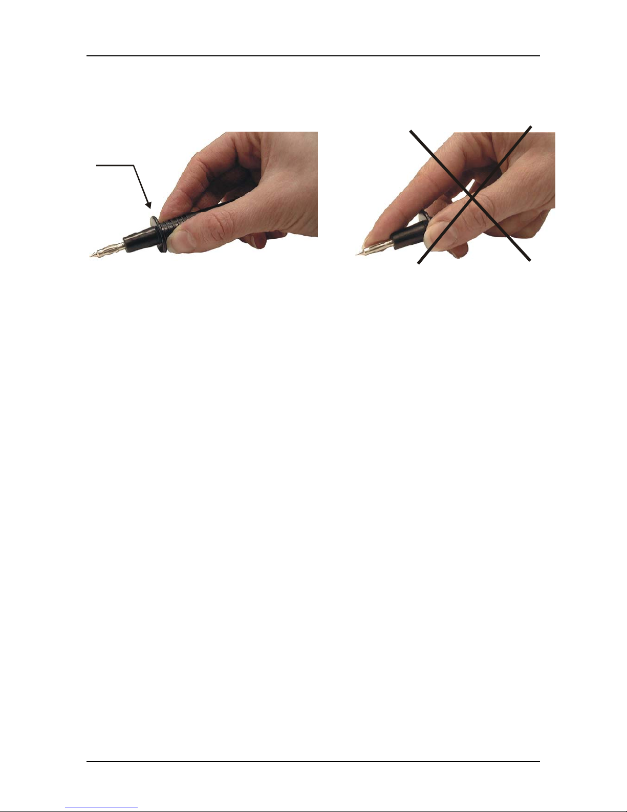
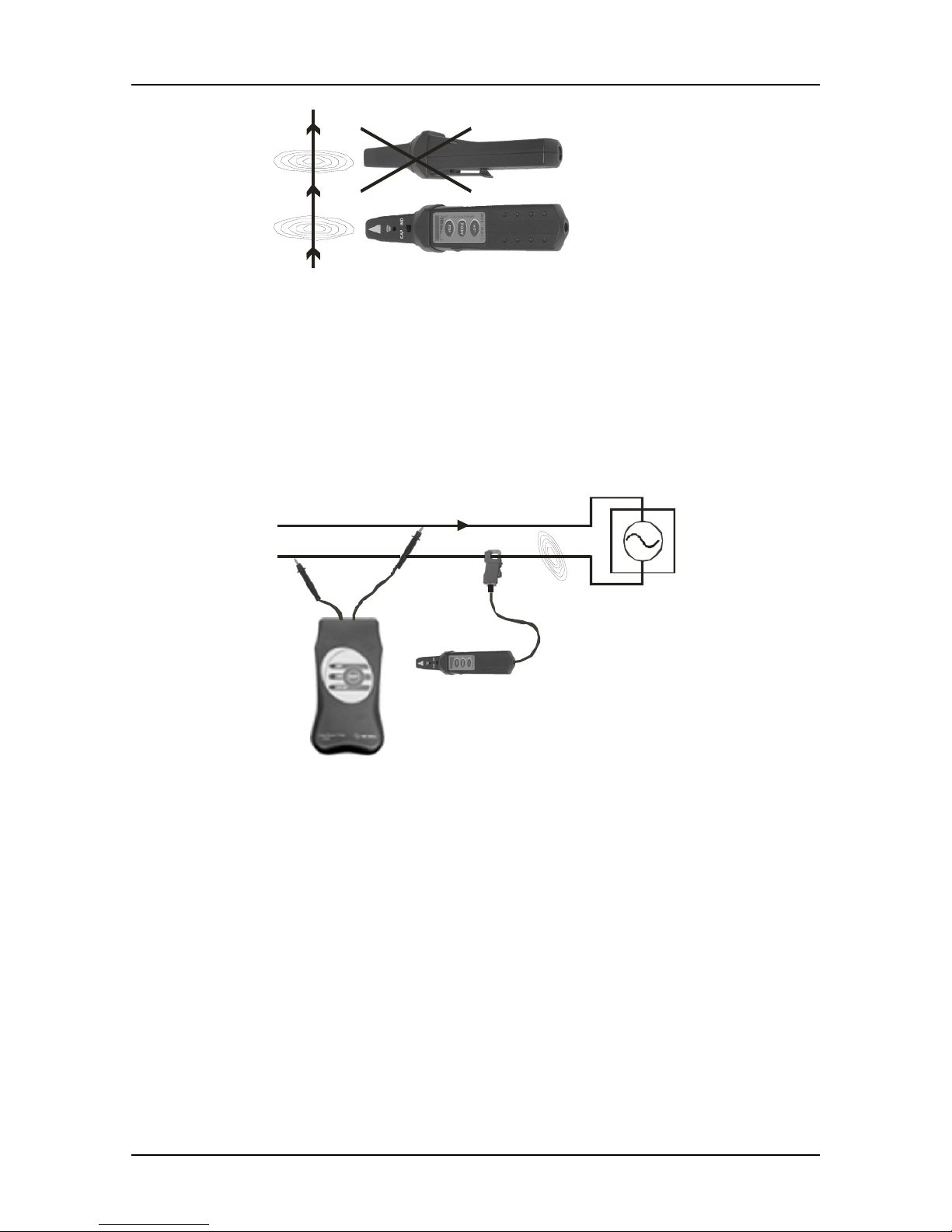
• Never touch metal tip of test probes or put fingers over protection barrier. See the
figure below:
Barrier
Correct and safety
Wrong and
Hazardous live
• Max tip voltage = 250 V ≅
1.4. Fields of Use
The primary fields of use are electrical installations but the
Line Tracer can be also a
useful tool in telecommunications, computer network installations and elsewhere.
The main activities that can be carried out:
• Tracing cables in walls, ceilings, floor and ground.
• Tracing live or voltage free cables.
• Locating cable interruptions and short-circuits in cables.
• Locating concealed sockets and distribution boxes.
• Locating fuses and assignment to circuits.
• Determining an individual wire in a bundle of wires.
• Detecting the energized state of traced installation.
• Tracing pipe installations and other conductive loops.
Note: when using the
Line Tracer MI 2093 for the first time, it is recommended to apply
it on known object, e.g. a known cable location in the wall, known fuses etc. In this way
the user gains the necessary skill for performing the measurements.
1.5. Transmitter T10K
The
transmitter T10K generates signal, which is connected to a traced object. The
state of an external voltage present at the output terminals selects one of the two
modes of generating the test signal.
Page 6
Line Tracer
6
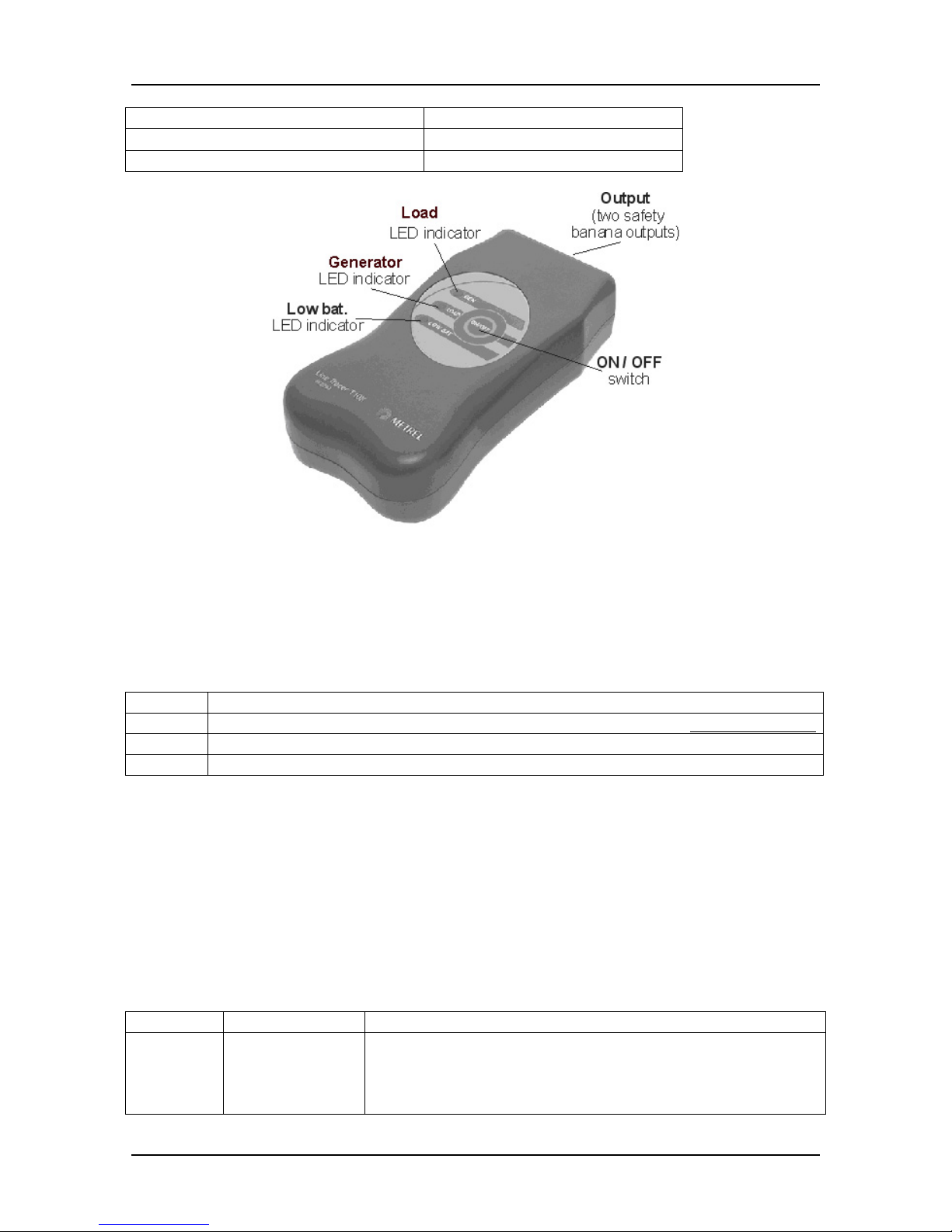
External voltage on terminals Test signal generating mode
30 V ÷ 264 V, a.c., 50 Hz or 60 Hz
Active load
d.c. or < 30 V a.c. Internal source
Fig. 1. Transmitter T10K
In both modes 10.6 kHz signal bursts are injected directly into the connected line or
coupled via an optional current clamp.
Led indicators on the
transmitter T10K have the following meaning:
All off
The transmitter is switched off
Low bat
The battery is empty and has to be replaced with a new one, see chapter 5.1.
LOAD
The transmitter generates signal as the active load
GEN
The internal source is activated
The transmitter T10K is supplied by 4 alkaline AA size (IEC LR 6) battery cells.
1.6. Receiver R10K
The highly sensitive hand-held Receiver R10K detects the injected signal around the
traced line. It generates sound and visual output relative to the signal intensity. Its
constructional designed points with its head detector to the maximum of detected signal
and the center of traced object. The slide switch of head detector enables the selection
between two built-in sensors.
Detector Sensor selector Recommendations
Inductive Slide switch
IND
- traced object is normally energized
- transmitter acts as active load
- loading current generates magnetic field around
conductor
Page 7

Line Tracer
7
Capacitive Slide switch
CAP
- traced object is normally voltage free
- transmitter has its internal source activated
- object acts as electrical field radiator
External Rear connector
- for additional accessories like current clamp, electric
probe tip and selective sensor
- keep maximum distance to traced object in order to
avoid interference of received signals through sensor
head
Sound
opening
Low bat.
indicator
Inductive / Capacitive
switch
LED bargraph
Power ON
LED indicator
Potentiometer
for fine adjustment
ON / GAIN keys
Input conector
(probe, current
clamp)
Sensitive
area
Safety barrier
Fig. 2. Receiver R10K
You can choose between three sensitivities (low, middle and high). An extra
potentiometer is added for fine sensitivity adjustment. A buzzer sound and 10-level LED
bar graph indicator suffice to indicate the location of the traced object.
Notes:
Always select sensitivity that is optimal for individual tracing. The sensitivity can be
changed during tracing.
Do not connect imput connector to hazardous alive voltage
The receiver R10K is supplied by a 9V alkaline battery (IEC 6LR61).
Page 8
Line Tracer
8
2. Operation principle
2.1. Fundamentals
Decision for tracing mode selection depends on the object, its structure, energized state
and many other reasons. Understanding the electric and magnetic field characteristics
leads to selecting the most applicable method. For most of the applications good
sensitivity is required, especially when the searched conductor is located far away.
Contrary to this the minimum sensitivity is required for selection of a searched
conductor in a group of similar conductors. The sensitivity will be in-between for finding
appropriate protective device (fuse) or conductors in the proximity.
The basis for all tracing of this kind is that the traced object is electrically conductive.
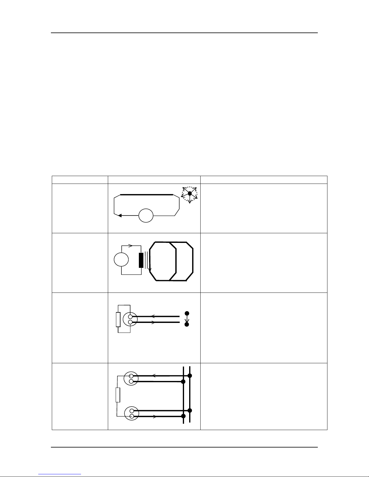
Current loops and electromagnetic field
Magnetic field is always present around current carrying conductors.
Example Basic circuit Description
Free conductor
H
~
I
- magnetic field (H) is distributed
around conductor
- current (I) is limited to internal
source capability
- INDuctive sensor is applicable for
tracing
Metallic loops
~
I
n
nI
CT
1
2
- current is transformed with a clamp
transformer (CT) n times to n
⋅I
- always the shortest path (e.g. 1)
carry maximum current and is
traceable
- INDuctive sensor is applicable for
tracing
Single wall
socket
connection
I
ALS
L
N
H
- active load source (ALS) generates
current
- major part of magnetic field (H) is
concentrated in a gap between
conductors
- rest of the field depends on wire
distance
- INDuctive sensor is applicable for
tracing (up to a few cm distance)
Two wall
sockets with
different
conduits to the
point of
common
coupling
I
ALS
L
N
I
- active load source (ALS) generates
current
- magnetic field is distributed around
each of current carrying conductors
- INDuctive sensor is applicable for
tracing
Page 9
Line Tracer
9
Notes:
Inductive sensor contains a winding. The best sensitivity is always achieved when the
winding axis is parallel to the magnetic field around the searched object. Always try to
find the best signal by rotating the sensor around its axis.
The traced object with good conductivity has very low voltage drop and weak electrical
field in parallel with it.
If a source in active load mode is connected to the energized line with significant
internal impedance then voltage variations of loading are also sources of electrical field
around line. The detectability of the electrical field is mentioned below.
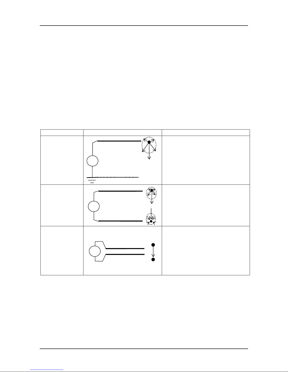
Electric field
Electric field is always present between two conductors or points of different potential. In
most cases the potential is between a conductor and ground or between two neighbor
conductors.
Example Basic circuit Description
Free conductor
~
U
E
- electrical field is distributed
around conductor
- maximum magnitude of electric
field between conductor and
closest conductive ground
- CAPacitive sensor is applicable
for tracing
Two conductors
and wide
distance
~
U
E
- electrical field is distributed
around each conductor
- maximum magnitude of electric
field between conductors
- CAPacitive sensor is applicable
for tracing
Two conductors
and tiny
distance
~
U
E
- major part of electric field is
concentrated in a gap between
conductors
- rest of the field depends on
distance between conductors
- CAPacitive sensor is applicable
for tracing (up to a few cm
distance)
Note for shielded conductor:
if source (U) is connected between inner conductor and shield no field can be detected.
Page 10

Line Tracer
10
2.2. Tracing the electromagnetic field of lines
a) Energized lines, the transmitter in LOAD mode
Hints:
When the transmitter is connected to energized lines the loop is determined with the
mains transformer.
Tracing this way will give the best results and selectivity because of high values of the
injected current.
The tracing principle allows accurate tracing even on longer distances.
Receiver R10K
switched in
inductive mode
Transmitter T10K
is automatically
in load mode
LINES: energized
MAINS
SUPPLY
I
Fig. 3. Transmitter as active load
Detection possibilities for traced object
Tracing object Distance up
to
Notes
Pair of
conductors
Up to 40 cm - one wall socket connection
Wide
conductor loop
Up to 2 m
- connection between L in one wall socket and N in
the other with separated conduits
Note: proper connection is indicated with LED LOAD
on transmitter (LED lights when voltage is present)
Hints, continued:
The position of the Receiver must be considered (see the figures below)! Also wire
direction can be defined this way.
Page 11
Line Tracer
11
Re c eiver R1 0K
sw itch ed in uc tive m odeIN
D
correct
position
Fig. 4. Detection of electromagnetic field
Whenever it is possible to embrace the traced wire or pipe it is recommended to use the
appropriate current clamp instead of the receiver’s inductive sensor (see figure below).
By using the clamp, the signal selectivity will considerably improve.
Always keep maximum distance between current clamp and R10K.
LINES: energized
MAINS
SUPPLY
I
Receiver R1 0K
switc hed in
inductive mode
Transmitter T10K
is automatically
in load mode
Fig. 5. Transmitter as active load, clamp used instead of inductive sensor
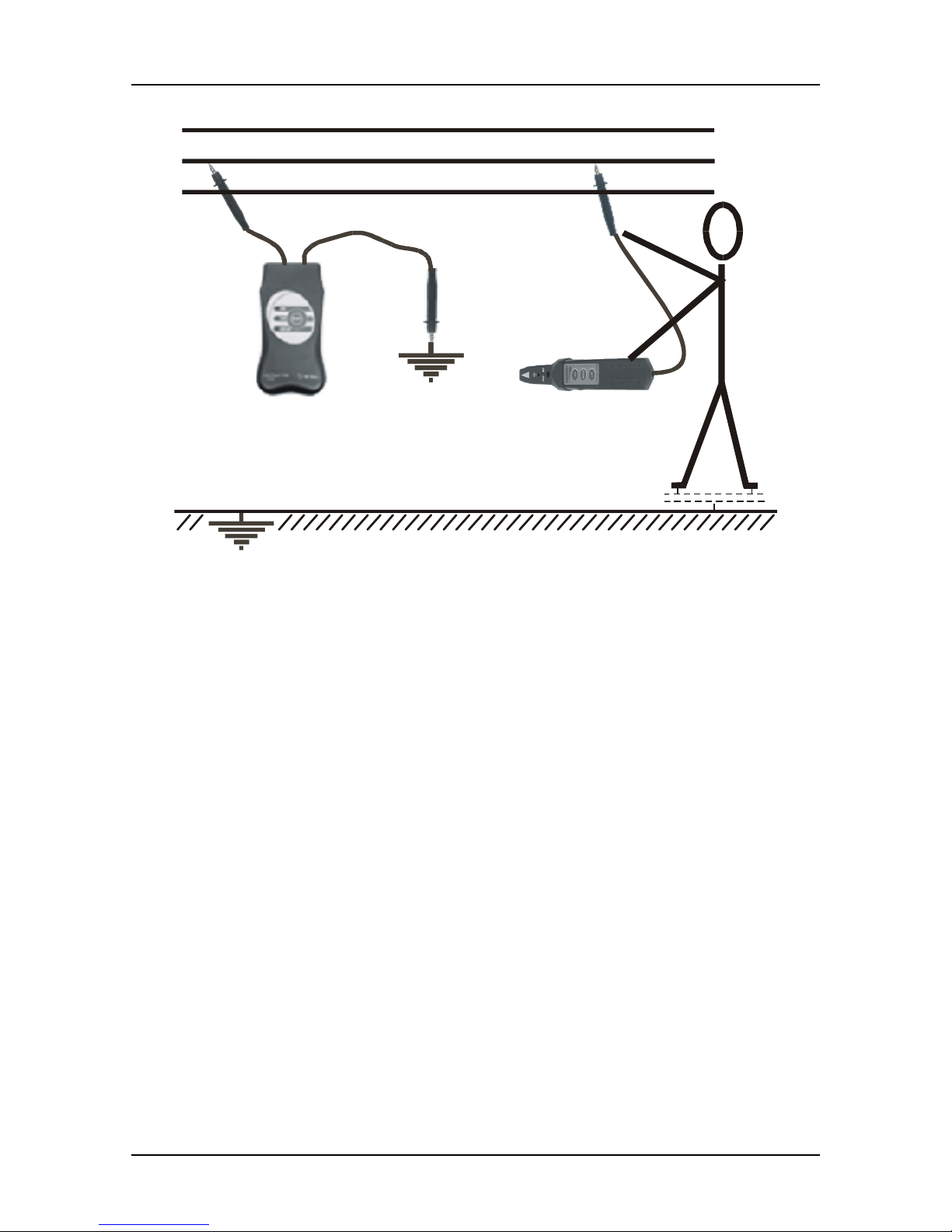
For searching a fuse in a group of them the selective probe should be applied.
With it the housing of the fuse or wire must be touched at the right angle.
Find the best signal by rotating the probe.
Keep maximum distance between R10K and selective probe.
Note: keep fingers behind the probe barrier to avoid electric shock and access of live
parts.
Page 12

Line Tracer
12
ON
Transmitter T10K
is in modeLO AD
En ergiz e d s yst e m
Receiver R10K
Selective probe
Fig. 6. Searching the fuse
b) Non-energized lines, the transmitter in GEN mode
Hints: continued
When the traced lines are in short circuit, the test current from internal generator of the
transmitter unit T10K flows through the tested loop.
This can also happen in case of cable shorts, connected bulbs or other loads etc.
Receiver R10K
switched in
inductive mode
Tran smitter T10K
is automatically
in generator mode
LINES: Non-energized or DC powered
I
Fig. 7. Injection of test current into tested loop
Detection possibilities for traced object
Tracing object Distance Notes
Pair of conductors Up to 5 cm
Page 13

Line Tracer
13
Hints: continued
When tracing conductive loops like pipe installation it is often not possible to disconnect
them from each other (taps, radiators etc). In such situations it is possible to inject the
test signal into the loop by using a current clamp.
Receiver R10K
switc hed in
inductive mode
Transmitter T10K
is automatically
in generator mode
CONDUCTIVE LOOP (wires, pipes etc.)
I
Fig. 8. Injection of test current into closed tested loop by means of current clamp
Detection possibilities for traced object
Tracing object Distance up to Notes
Wire, pipe 10 cm Pay attention to shorts that reduce basic loop size
Page 14

Line Tracer
14
2.3. Tracing the electrical field of lines
Hints:
The traced line should be insulated from ground to receive a strong and selective signal.
Switches and loads must be switched off (switch off the main transformers, grounding
capacitors etc.) to prevent attenuation of the injected signal.
If the traced line has ground connection, then the current flows and it is possible to trace
in inductive mode of the receiver.
LINES: Non-energized DC powered
Receiver R10K
switched in
capacitive mode
Transmitter T10K
is automatically
in generator mode
Fig. 9. Tracing the electrical field of a line
Detection possibilities for the traced object
Tracing object Distance up to Notes
Conductor 30 cm
Whenever the traced line or a part of the traced line is accessible it is recommended to
use the appropriate Test Tip, connected to the Receiver R10K (see the figure below).
The signal selectivity will be improved by using the test tip.
This allows applications like determining fuses, individual wires in a tuft of wires etc. In
that case LOW sensitivity key for lowest signal gain is recommended.
Page 15
Line Tracer
15
LINES: Non-energized DC powered
Transmitter T10K
is automatically
in generator mode
Fig. 10. Tracing the conductor using Test tip
Page 16
Line Tracer
16
3. Typical applications
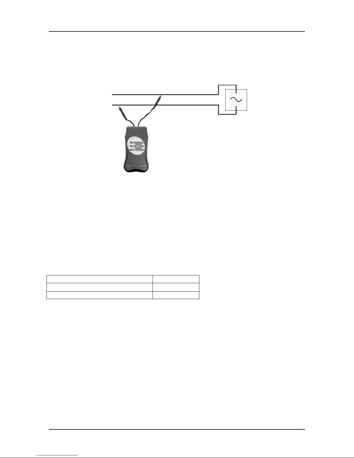
3.0. Detecting energized state of installation
Unknown state of installation
MAINS
SUPPLY
LEDs LOAD and GEN of
Transmitter T10K
indicate state
Fig. 11. Transmitter acts as energized state detector
The transmitter T10K automatically recognizes the energized state of the line connected
to. As mentioned in paragraph 1.5. the LED indicators, i.e. LOAD and GEN, show
internal working condition.
The following table contains the two possible states:
External voltage on terminals LED activated
30 V ÷ 264 V, a.c., 50 Hz or 60 Hz
LOAD
d.c. or <30 V a.c. GEN
Page 17
Line Tracer
17
3.1. Tracing Cables in Walls, Ceilings, Floor and Ground, and
Defected Fuses
Tracing of Hidden Wires on Non-energized Systems
OFF
Receiver R10K
switched in
capacitive mode
Transmitter T10K
is automatically
in gen era to r mode
Fig. 12. Tracing cable or determination of the belonging fuse on non-energized
installation. The receiver detects the electrical field, caused by the voltage generation of
the transmitter.
Tracing Cables in Walls, Ceilings, Floor and Ground on Energized Systems
ON
Receiv er R10K
switched in
inductive mode
Transmitter T10K
is automatically
in load mo de
Fig. 13. Tracing cable or determination of the belonging fuse on energized installation.
The receiver detects the electromagnetic field caused by load current of the transmitter.
Note: The tracing distance can be increased, if the transmitter is connected to N of one
wall socket and L of another wall socket.
Page 18
Line Tracer
18
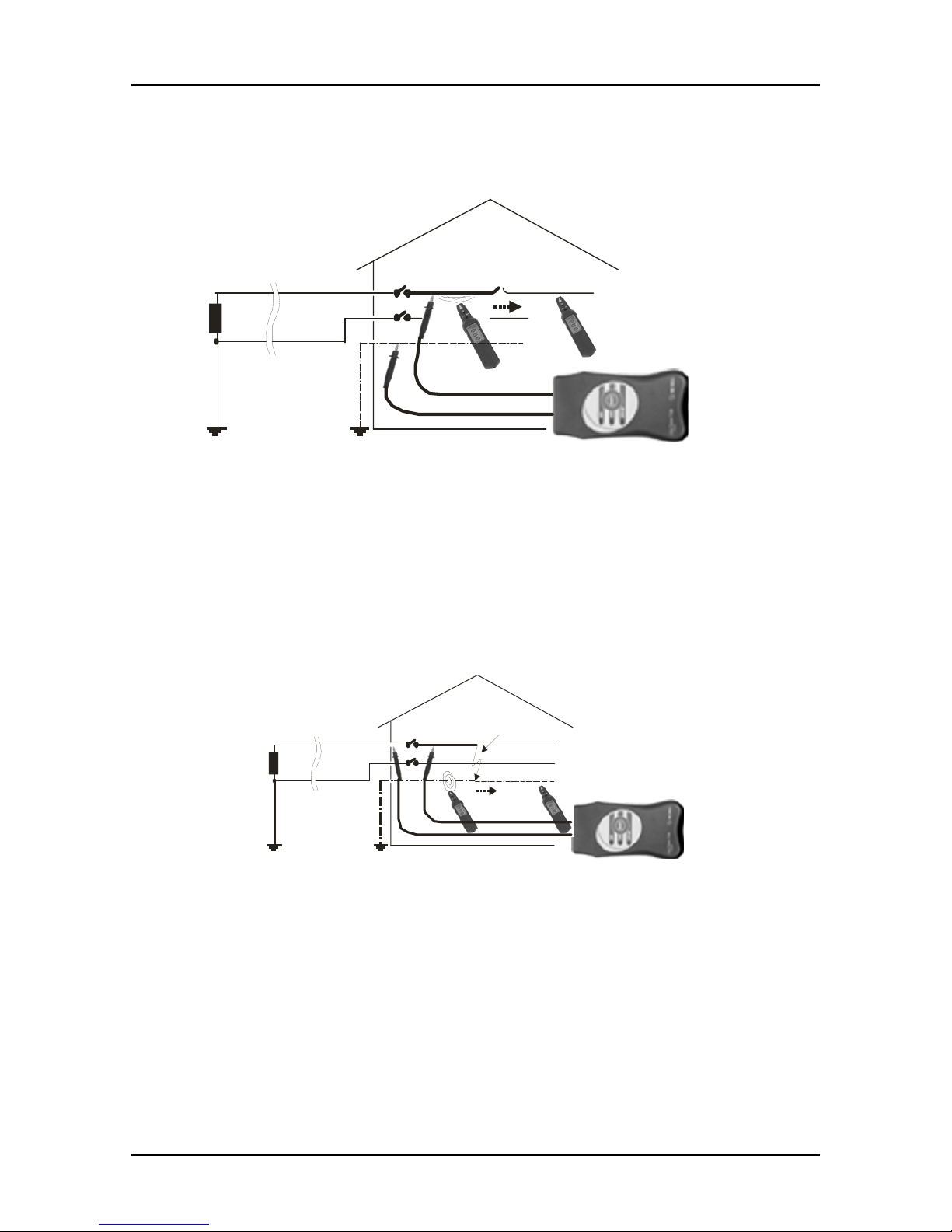
3.2. Determining Cable Faults
Locating cable interruptions
L1
N
Ro RE
Interruption
OFF
No
signal
Rec eiver R1 0K
sw itch e d in
capacitive mode
Transmitter T10K
is automatically
in generator mode
Fig. 14. Determination of interruption location-electrical field caused by transmitter
disappears behind the interruption.
Locating earth fault
L1
N
Ro RE
short circuit
OFF
no
signal
Receiver R10K
sw i t c he d in
inductive mode
Transmitter T10K
is automatically
in generator mode
Fig. 15. Determination of short circuit location
Electromagnetic field disappears behind the short circuit location.
Attention: Load current of Transmitter is 1 A. Therefore for the safety reasons the max.
value of RE is less then 50
Ω.
Page 19

Line Tracer
19
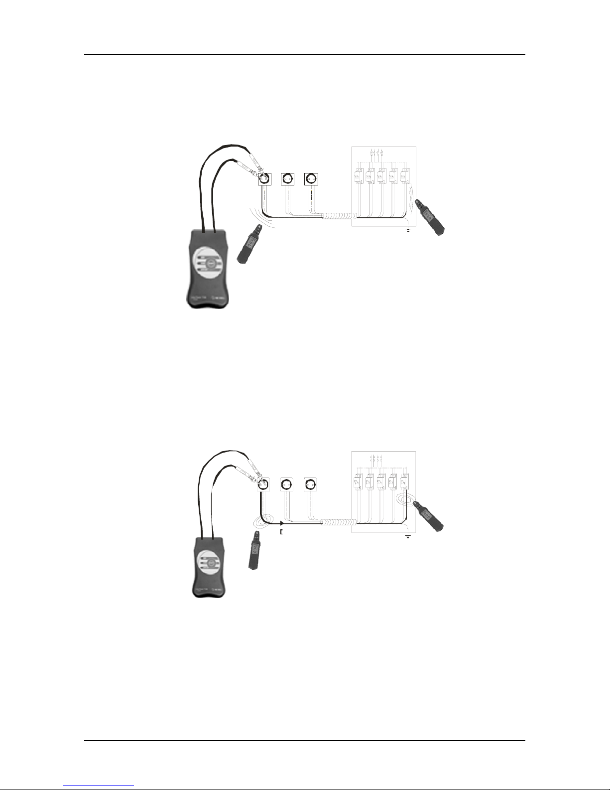
3.3. Determining Individual Wires, Fuses etc.
Using Special Test Tip
A 1067
LINES: unactive or DC powere
d
Receiv er R1 0K
switched in
capacitive mode
Transmitter T10K
is automatically
in generator mode
Fig. 16. Determination of individual wire
The Test Tip connected to the receiver is used for determining an individual wire. The
lowest gain is recommended for this kind of application (LOW gain)
Using Special Current Clamp
A 1069
ON
Transmitter T10K
is automatically
in load mode
Fig. 17. Determination of the belonging fuse by using current clamp
Current clamp can be used to exactly determine an individual wire or belonging fuse. It
is recommended to use the lowest gain for this purpose (LOW gain).
Page 20
Line Tracer
20
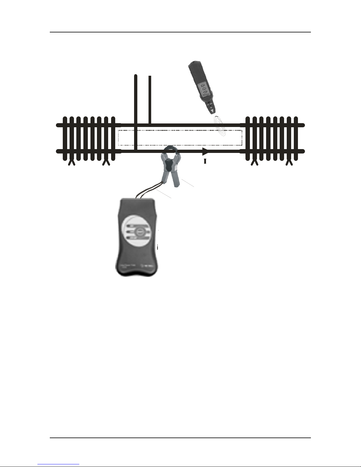
Using Current Clamp for Current-Signal Injection
CONDUCTIVE LOOP
Re ceiv er R10K
switched in
inductive mode
Transmitter T10K
is automatically
in generator mode
A 1019
A 1068
Fig. 18. Tracing conductive loops by using current clamp
Instead of a direct current-signal injection, clamp can be used for this purpose and
conductive loop can be traced afterwards.
Page 21

Line Tracer
21
4. Tehnical characteristics
4.1 Transmitter T10K
Batteries: 4 x AA size (1.5 V)
Low battery indicator: Built in
Operating temperature: 0
°C – +40 °C
Storage temperature: -30
°C – +60 °C
Weight: 280 g
Housing: ABS plastics
Dimensions: 80 mm x 50 mm x 150 mm
Overvoltages CAT III 300 V
Pollution degree 2
Automatic switching between generator and load mode according to input voltage.
Transmitter T10K in Generator Mode
DC, AC voltage: < 30 V or no voltage present on line
Operating frequency: 10.6 KHz modulated with 4 Hz
Maximum open circuit voltage: 6 V r.m.s.
Maximum short circuit current: 20 mA r.m.s.
Transmitter T10K in Load Mode
System voltage necessary for transmitting: 30 V ÷ 264 V, a.c.
System frequency: 45 Hz
÷ 65 Hz
Operating frequency: 10.6 KHz modulated with 4 Hz
Maximum average injected current: 1 A r.m.s.
4.2. Receiver R10K
Battery: 1 x 6LR61 size (9 V)
Low battery indicator: Built in
Operating temperature: 0
°C – +40 °C
Storage temperature: -30
°C – +60 °C
Weight: 140 g
Housing: ABS plastics
Dimensions: 45 mm x 45 mm x 210 mm
Built-in mechanical switch to select between capacitive and inductive mode.
Sensor: Built-in capacitive sensor for electric field tracing
and inductive sensor for magnetic field tracing
Selectivity: Input band-pass filter 10.6 KHz
Indicators: Audio - piezoelectric speaker (70 dB)
Visual - 10 level LED bargraph-style indicator
Sensitivity: LOW, MIDDLE, HIGH sensitivity keys, potentiometer for fine
adjustment of signal gain
Page 22

Line Tracer
22
5. Meintenance
5.1. Battery Replacement for Transmitter T10K
Disconnect all test leads before opening the battery cover.
Unscrew all four screws at the bottom of case.
Remove the cover.
Replace all four battery cells. Pay attention to correct battery polarity.
Fix the cover with all four screws to original position.
The transmitter is energized with four alkaline AA size 1.5 V battery cells.
5.2. Battery Replacement for Receiver R10K
Unscrew two screws on the bottom of casing.
Remove the cover.
Replace the battery. Pay attention to correct battery polarity.
Fix the cover back to the original position.
Receiver is energized with one 9 V battery (IEC 6LR61).
5.3. Cleaning
Use soft patch moistened by water or alcohol, and leave the instrument to dry totally
after the cleaning.
Do not use liquids based on petrol!
Do not spill cleaning liquid over the instrument!
5.4. Service
In case of any instrument malfunction or damage, noticed on the instrument or its
accessories, a competent service department must service the instrument. Contact your
dealer for detailed information.
Page 23

Line Tracer
23
6. Ordering information
6.1. Standard Set
Order no.: MI 2093
Transmitter T10K
Receiver R10K
Two test leads (safety banana on both sides), black, 1.5 m, (for T10K)
Special selective tip probe
Test tip, 2pcs
Alligator clip, 2pcs
Small soft carrying bag
6.2. Optional accessories
Current clamp 1000 A / 1 A, d = 52 mm A 1019
Test lead, 1.5 m, with built in resistor, (for R10K) A 1067
Connection cable for clamp A 1068
Current clamp 200 A / 0.2 A, d = 15 mm A 1074
Page 24

 Loading...